

Page 1

2910al
ProCurve Switches
W.14.03
Access Security Guide
www.procurve.com
Page 2

Page 3

HP ProCurve 2910al Switch
Access Security Guide
February 2009
W.14.03
Page 4

© Copyright 2009 Hewlett-Packard Development Company,
L.P. The information contained herein is subject to change without notice. All Rights Reserved.
This document contains proprietary information, which is
protected by copyright. No part of this document may be
photocopied, reproduced, or translated into another langauge without the prior written consent of Hewlett-Packard.
Publication Number
5992-5439
February 2009
Applicable Products
HP ProCurve 2910al-24G Switch J9145A
HP ProCurve 2910al-48G Switch J9147A
HP ProCurve 2910al-24G-PoE+ Switch J9146A
HP ProCurve 2910al-48G-PoE+ Switch J9148A
HP ProCurve 2-Port 10-GbE SFP+ al Module J9008A
HP ProCurve 2-Port 10-GbE CX4 al Module J9149A
HP ProCurve 10-GbE al Interconnect Kit J9165A
Trademark Credits
Microsoft, Windows, and Microsoft Windows NT are U.S.
registered trademarks of Microsoft Corporation.
Software Credits and Notices
SSH on ProCurve Switches is based on the OpenSSH software toolkit. This product includes software developed by
the OpenSSH Project for use in the OpenSSH Toolkit. For
more information on OpenSSH, visit www.openssh.com.
SSL on ProCurve Switches is based on the OpenSSL software
toolkit. This product includes software developed by the
OpenSSL Project for use in the OpenSSL Toolkit. For more
information on OpenSSL, visit
www.openssl.org.
This product includes cryptographic software written by
Eric Young (eay@cryptsoft.com). This product includes
software written by Tim Hudson (tjh@cryptsoft.com).
Portions of the software on ProCurve switches are based on
the lightweight TCP/IP (lwIP) software toolkit by Adam
Dunkels, and are covered by the following notices.
Copyright © 2001-2003 Swedish Institute of Computer
Science. All rights reserved. Redistribution and use in source
and binary forms, with or without modification, are
permitted provided that the following conditions are met:
1. Redistributions of source code must retain the above
copyright notice, this list of conditions and the following
disclaimer.
2. Redistributions in binary form must reproduce the above
copyright notice, this list of conditions and the following
disclaimer in the documentation and/or other materials
provided with the distribution.
3. The name of the author may not be used to endorse or
promote products derived from this software without
specific prior written permission.
THIS SOFTWARE IS PROVIDED BY THE AUTHOR ``AS IS''
AND ANY EXPRESS OR IMPLIED WARRANTIES, INCLUDING, BUT NOT LIMITED TO, THE IMPLIED WARRANTIES OF MERCHANTABILITY AND FITNESS FOR A PARTICULAR PURPOSE ARE DISCLAIMED. IN NO EVENT
SHALL THE AUTHOR BE LIABLE FOR ANY DIRECT, INDIRECT, INCIDENTAL, SPECIAL, EXEMPLARY, OR CONSEQUENTIAL DAMAGES (INCLUDING, BUT NOT LIMITED TO, PROCUREMENT OF SUBSTITUTE GOODS OR
SERVICES; LOSS OF USE, DATA, OR PROFITS; OR BUSINESS INTERRUPTION) HOWEVER CAUSED AND ON ANY
THEORY OF LIABILITY, WHETHER IN CONTRACT,
STRICT LIABILITY, OR TORT (INCLUDING NEGLIGENCE
OR OTHERWISE) ARISING IN ANY WAY OUT OF THE USE
OF THIS SOFTWARE, EVEN IF ADVISED OF THE POSSIBILITY OF SUCH DAMAGE.
This product includes software written by Adam Dunkels
(adam@sics.se).
Disclaimer
The information contained in this document is subject to
change without notice.
HEWLETT-PACKARD COMPANY MAKES NO WARRANTY
OF ANY KIND WITH REGARD TO THIS MATERIAL,
INCLUDING, BUT NOT LIMITED TO, THE IMPLIED
WARRANTIES OF MERCHANTABILITY AND FITNESS
FOR A PARTICULAR PURPOSE. Hewlett-Packard shall not
be liable for errors contained herein or for incidental or
consequential damages in connection with the furnishing,
performance, or use of this material.
The only warranties for HP products and services are set
forth in the express warranty statements accompanying
such products and services. Nothing herein should be
construed as constituting an additional warranty. HP shall
not be liable for technical or editorial errors or omissions
contained herein.
Hewlett-Packard assumes no responsibility for the use or
reliability of its software on equipment that is not furnished
by Hewlett-Packard.
Warranty
See the Customer Support/Warranty booklet included with
the product.
A copy of the specific warranty terms applicable to your
Hewlett-Packard products and replacement parts can be
obtained from your HP Sales and Service Office or
authorized dealer.
Hewlett-Packard Company
8000 Foothills Boulevard, m/s 5551
Roseville, California 95747-5551
www.procurve.com
Page 5

Contents
Product Documentation
About Your Switch Manual Set . . . . . . . . . . . . . . . . . . . . . . . . . . . . xix
Printed Publications. . . . . . . . . . . . . . . . . . . . . . . . . . . . . . . . . . . . . . . . . . xix
Electronic Publications . . . . . . . . . . . . . . . . . . . . . . . . . . . . . . . . . . . . . . . xix
Software Feature Index. . . . . . . . . . . . . . . . . . . . . . . . . . . . . . . . . . . xx
1 Security Overview
Contents . . . . . . . . . . . . . . . . . . . . . . . . . . . . . . . . . . . . . . . . . . . . . . . . . . . . . . 1-1
Introduction . . . . . . . . . . . . . . . . . . . . . . . . . . . . . . . . . . . . . . . . . . . . . . . . . . 1-2
About This Guide . . . . . . . . . . . . . . . . . . . . . . . . . . . . . . . . . . . . . . . . . . . . 1-2
For More Information . . . . . . . . . . . . . . . . . . . . . . . . . . . . . . . . . . . . . . . . 1-2
Access Security Features . . . . . . . . . . . . . . . . . . . . . . . . . . . . . . . . . . . . . . 1-3
Network Security Features . . . . . . . . . . . . . . . . . . . . . . . . . . . . . . . . . . . . 1-7
Getting Started with Access Security . . . . . . . . . . . . . . . . . . . . . . . . . . 1-10
Physical Security . . . . . . . . . . . . . . . . . . . . . . . . . . . . . . . . . . . . . . . . . . . 1-10
Quick Start: Using the Management Interface Wizard . . . . . . . . . . . . 1-11
CLI: Management Interface Wizard . . . . . . . . . . . . . . . . . . . . . . . . 1-12
Web: Management Interface Wizard . . . . . . . . . . . . . . . . . . . . . . . 1-13
SNMP Security Guidelines . . . . . . . . . . . . . . . . . . . . . . . . . . . . . . . . . . . 1-16
Precedence of Security Options . . . . . . . . . . . . . . . . . . . . . . . . . . . . . . . 1-18
Precedence of Port-Based Security Options . . . . . . . . . . . . . . . . . . . . 1-18
Precedence of Client-Based Authentication:
Dynamic Configuration Arbiter . . . . . . . . . . . . . . . . . . . . . . . . . . . . . . . 1-18
Network Immunity Manager . . . . . . . . . . . . . . . . . . . . . . . . . . . . . . 1-19
Arbitrating Client-Specific Attributes . . . . . . . . . . . . . . . . . . . . . . 1-20
ProCurve Identity-Driven Manager (IDM) . . . . . . . . . . . . . . . . . . . . . 1-22
iii
Page 6

2 Configuring Username and Password Security
Contents . . . . . . . . . . . . . . . . . . . . . . . . . . . . . . . . . . . . . . . . . . . . . . . . . . . . . . 2-1
Overview . . . . . . . . . . . . . . . . . . . . . . . . . . . . . . . . . . . . . . . . . . . . . . . . . . . . . 2-3
Configuring Local Password Security . . . . . . . . . . . . . . . . . . . . . . . . . . . 2-6
Menu: Setting Passwords . . . . . . . . . . . . . . . . . . . . . . . . . . . . . . . . . . . . . 2-6
CLI: Setting Passwords and Usernames . . . . . . . . . . . . . . . . . . . . . . . . . 2-8
Web: Setting Passwords and Usernames . . . . . . . . . . . . . . . . . . . . . . . . 2-9
SNMP: Setting Passwords and Usernames . . . . . . . . . . . . . . . . . . . . . . 2-9
Saving Security Credentials in a
Config File . . . . . . . . . . . . . . . . . . . . . . . . . . . . . . . . . . . . . . . . . . . . . . . . . . . 2-10
Benefits of Saving Security Credentials . . . . . . . . . . . . . . . . . . . . . . . . 2-10
Enabling the Storage and Display of Security Credentials . . . . . . . . 2-11
Security Settings that Can Be Saved . . . . . . . . . . . . . . . . . . . . . . . . . . . 2-11
Local Manager and Operator Passwords . . . . . . . . . . . . . . . . . . . . . . . 2-12
Password Command Options . . . . . . . . . . . . . . . . . . . . . . . . . . . . . . . . 2-13
SNMP Security Credentials . . . . . . . . . . . . . . . . . . . . . . . . . . . . . . . . . . 2-14
802.1X Port-Access Credentials . . . . . . . . . . . . . . . . . . . . . . . . . . . . . . . 2-15
TACACS+ Encryption Key Authentication . . . . . . . . . . . . . . . . . . . . . 2-15
RADIUS Shared-Secret Key Authentication . . . . . . . . . . . . . . . . . . . . 2-16
SSH Client Public-Key Authentication . . . . . . . . . . . . . . . . . . . . . . . . . 2-16
Operating Notes . . . . . . . . . . . . . . . . . . . . . . . . . . . . . . . . . . . . . . . . . . . . 2-19
Restrictions . . . . . . . . . . . . . . . . . . . . . . . . . . . . . . . . . . . . . . . . . . . . . . . 2-21
iv
Front-Panel Security . . . . . . . . . . . . . . . . . . . . . . . . . . . . . . . . . . . . . . . . . 2-23
When Security Is Important . . . . . . . . . . . . . . . . . . . . . . . . . . . . . . . . . . 2-23
Front-Panel Button Functions . . . . . . . . . . . . . . . . . . . . . . . . . . . . . . . . 2-24
Clear Button . . . . . . . . . . . . . . . . . . . . . . . . . . . . . . . . . . . . . . . . . . . 2-24
Reset Button . . . . . . . . . . . . . . . . . . . . . . . . . . . . . . . . . . . . . . . . . . . 2-25
Restoring the Factory Default Configuration . . . . . . . . . . . . . . . . 2-25
Configuring Front-Panel Security . . . . . . . . . . . . . . . . . . . . . . . . . . . . . 2-26
Disabling the Clear Password Function of the Clear Button
on the Switch’s Front Panel . . . . . . . . . . . . . . . . . . . . . . . . . . . . . . 2-29
Re-Enabling the Clear Button on the Switch’s Front Panel
and Setting or Changing the “Reset-On-Clear” Operation . . . . . 2-30
Changing the Operation of the Reset+Clear Combination . . . . . 2-31
Password Recovery . . . . . . . . . . . . . . . . . . . . . . . . . . . . . . . . . . . . . . . . . 2-32
Page 7

Disabling or Re-Enabling the Password Recovery Process . . . . 2-32
Password Recovery Process . . . . . . . . . . . . . . . . . . . . . . . . . . . . . . . . . 2-34
3 Web and MAC Authentication
Contents . . . . . . . . . . . . . . . . . . . . . . . . . . . . . . . . . . . . . . . . . . . . . . . . . . . . . . 3-1
Overview . . . . . . . . . . . . . . . . . . . . . . . . . . . . . . . . . . . . . . . . . . . . . . . . . . . . . 3-2
Web Authentication . . . . . . . . . . . . . . . . . . . . . . . . . . . . . . . . . . . . . . . . . 3-2
MAC Authentication . . . . . . . . . . . . . . . . . . . . . . . . . . . . . . . . . . . . . . . . . 3-3
Concurrent Web and MAC Authentication . . . . . . . . . . . . . . . . . . . . . . 3-3
Authorized and Unauthorized Client VLANs . . . . . . . . . . . . . . . . . . . . . 3-4
RADIUS-Based Authentication . . . . . . . . . . . . . . . . . . . . . . . . . . . . . . . . 3-5
Wireless Clients . . . . . . . . . . . . . . . . . . . . . . . . . . . . . . . . . . . . . . . . . . . . . 3-5
How Web and MAC Authentication Operate . . . . . . . . . . . . . . . . . . . . 3-5
Web-based Authentication . . . . . . . . . . . . . . . . . . . . . . . . . . . . . . . . . . . . 3-6
MAC-based Authentication . . . . . . . . . . . . . . . . . . . . . . . . . . . . . . . . . . . 3-8
Terminology . . . . . . . . . . . . . . . . . . . . . . . . . . . . . . . . . . . . . . . . . . . . . . . . . 3-10
Operating Rules and Notes . . . . . . . . . . . . . . . . . . . . . . . . . . . . . . . . . . . . 3-11
Setup Procedure for Web/MAC Authentication . . . . . . . . . . . . . . . . . 3-13
Before You Configure Web/MAC Authentication . . . . . . . . . . . . . . . . 3-13
Configuring the RADIUS Server To Support MAC Authentication . . 3-15
Configuring the Switch To Access a RADIUS Server . . . . . . . . . . . . 3-16
Configuring Web Authentication . . . . . . . . . . . . . . . . . . . . . . . . . . . . . . 3-18
Overview . . . . . . . . . . . . . . . . . . . . . . . . . . . . . . . . . . . . . . . . . . . . . . . . . . 3-18
Configuration Commands for Web Authentication . . . . . . . . . . . . . . 3-19
Show Commands for Web Authentication . . . . . . . . . . . . . . . . . . . . . . 3-26
Configuring MAC Authentication on the Switch . . . . . . . . . . . . . . . . 3-32
Overview . . . . . . . . . . . . . . . . . . . . . . . . . . . . . . . . . . . . . . . . . . . . . . . . . . 3-32
Configuration Commands for MAC Authentication . . . . . . . . . . . . . . 3-33
Show Commands for MAC-Based Authentication . . . . . . . . . . . . . . . 3-36
Client Status . . . . . . . . . . . . . . . . . . . . . . . . . . . . . . . . . . . . . . . . . . . . . . . . . 3-42
v
Page 8

4 TACACS+ Authentication
Contents . . . . . . . . . . . . . . . . . . . . . . . . . . . . . . . . . . . . . . . . . . . . . . . . . . . . . . 4-1
Overview . . . . . . . . . . . . . . . . . . . . . . . . . . . . . . . . . . . . . . . . . . . . . . . . . . . . . 4-2
Terminology Used in TACACS Applications: . . . . . . . . . . . . . . . . . . . . 4-3
General System Requirements . . . . . . . . . . . . . . . . . . . . . . . . . . . . . . . . . 4-5
General Authentication Setup Procedure . . . . . . . . . . . . . . . . . . . . . . . 4-5
Configuring TACACS+ on the Switch . . . . . . . . . . . . . . . . . . . . . . . . . . . 4-8
Before You Begin . . . . . . . . . . . . . . . . . . . . . . . . . . . . . . . . . . . . . . . . . . . . 4-8
CLI Commands Described in this Section . . . . . . . . . . . . . . . . . . . . . . . 4-9
Viewing the Switch’s Current Authentication Configuration . . . . . . . 4-9
Viewing the Switch’s Current TACACS+
Server Contact Configuration . . . . . . . . . . . . . . . . . . . . . . . . . . . . . . . . 4-10
Configuring the Switch’s Authentication Methods . . . . . . . . . . . . . . . 4-11
Using the Privilege-Mode Option for Login . . . . . . . . . . . . . . . . . 4-11
Authentication Parameters . . . . . . . . . . . . . . . . . . . . . . . . . . . . . . . 4-13
Configuring the TACACS+ Server for Single Login . . . . . . . . . . . . . . 4-13
Configuring the Switch’s TACACS+ Server Access . . . . . . . . . . . . . . 4-18
How Authentication Operates . . . . . . . . . . . . . . . . . . . . . . . . . . . . . . . . . 4-24
General Authentication Process Using a TACACS+ Server . . . . . . . . 4-24
Local Authentication Process . . . . . . . . . . . . . . . . . . . . . . . . . . . . . . . . 4-25
Using the Encryption Key . . . . . . . . . . . . . . . . . . . . . . . . . . . . . . . . . . . 4-26
General Operation . . . . . . . . . . . . . . . . . . . . . . . . . . . . . . . . . . . . . . 4-26
Encryption Options in the Switch . . . . . . . . . . . . . . . . . . . . . . . . . 4-26
vi
Controlling Web Browser Interface
Access When Using TACACS+ Authentication . . . . . . . . . . . . . . . . . . 4-27
Messages Related to TACACS+ Operation . . . . . . . . . . . . . . . . . . . . . 4-28
Operating Notes . . . . . . . . . . . . . . . . . . . . . . . . . . . . . . . . . . . . . . . . . . . . . . 4-29
5 RADIUS Authentication and Accounting
Contents . . . . . . . . . . . . . . . . . . . . . . . . . . . . . . . . . . . . . . . . . . . . . . . . . . . . . . 5-1
Overview . . . . . . . . . . . . . . . . . . . . . . . . . . . . . . . . . . . . . . . . . . . . . . . . . . . . . 5-3
Authentication Services . . . . . . . . . . . . . . . . . . . . . . . . . . . . . . . . . . . . . . 5-3
Accounting Services . . . . . . . . . . . . . . . . . . . . . . . . . . . . . . . . . . . . . . . . . 5-4
Page 9

RADIUS-Administered CoS and Rate-Limiting . . . . . . . . . . . . . . . . . . . 5-4
SNMP Access to the Switch’s Authentication Configuration MIB . . . 5-4
Terminology . . . . . . . . . . . . . . . . . . . . . . . . . . . . . . . . . . . . . . . . . . . . . . . . . . 5-5
Switch Operating Rules for RADIUS . . . . . . . . . . . . . . . . . . . . . . . . . . . . 5-6
General RADIUS Setup Procedure . . . . . . . . . . . . . . . . . . . . . . . . . . . . . 5-7
Configuring the Switch for RADIUS Authentication . . . . . . . . . . . . . 5-8
Outline of the Steps for Configuring RADIUS Authentication . . . . . . 5-9
1. Configure Authentication for the Access Methods
You Want RADIUS To Protect . . . . . . . . . . . . . . . . . . . . . . . . . . . . . . . . 5-10
2. Enable the (Optional) Access Privilege Option . . . . . . . . . . . . . . . . 5-13
3. Configure the Switch To Access a RADIUS Server . . . . . . . . . . . . 5-15
4. Configure the Switch’s Global RADIUS Parameters . . . . . . . . . . . 5-17
Using SNMP To View and Configure
Switch Authentication Features . . . . . . . . . . . . . . . . . . . . . . . . . . . . . . . 5-21
Changing and Viewing the SNMP Access Configuration . . . . . . . . . . 5-22
Local Authentication Process . . . . . . . . . . . . . . . . . . . . . . . . . . . . . . . . . 5-24
Controlling Web Browser Interface Access . . . . . . . . . . . . . . . . . . . . 5-25
Commands Authorization . . . . . . . . . . . . . . . . . . . . . . . . . . . . . . . . . . . . . 5-26
Enabling Authorization . . . . . . . . . . . . . . . . . . . . . . . . . . . . . . . . . . . . . . 5-27
Displaying Authorization Information . . . . . . . . . . . . . . . . . . . . . . . . . 5-28
Configuring Commands Authorization on a RADIUS Server . . . . . . 5-28
Using Vendor Specific Attributes (VSAs) . . . . . . . . . . . . . . . . . . . 5-28
Example Configuration on Cisco Secure ACS for MS Windows 5-30
Example Configuration Using FreeRADIUS . . . . . . . . . . . . . . . . . 5-32
Additional RADIUS Attributes . . . . . . . . . . . . . . . . . . . . . . . . . . . . . . . . 5-34
Configuring RADIUS Accounting . . . . . . . . . . . . . . . . . . . . . . . . . . . . . . 5-35
Operating Rules for RADIUS Accounting . . . . . . . . . . . . . . . . . . . . . . 5-37
Steps for Configuring RADIUS Accounting . . . . . . . . . . . . . . . . . . . . . 5-37
1. Configure the Switch To Access a RADIUS Server . . . . . . . . . 5-38
2. Configure Accounting Types and the Controls for
Sending Reports to the RADIUS Server . . . . . . . . . . . . . . . . . . . . 5-40
3. (Optional) Configure Session Blocking and
Interim Updating Options . . . . . . . . . . . . . . . . . . . . . . . . . . . . . . . . 5-42
Viewing RADIUS Statistics . . . . . . . . . . . . . . . . . . . . . . . . . . . . . . . . . . . . 5-43
vii
Page 10

General RADIUS Statistics . . . . . . . . . . . . . . . . . . . . . . . . . . . . . . . . . . . 5-43
RADIUS Authentication Statistics . . . . . . . . . . . . . . . . . . . . . . . . . . . . . 5-45
RADIUS Accounting Statistics . . . . . . . . . . . . . . . . . . . . . . . . . . . . . . . . 5-46
Changing RADIUS-Server Access Order . . . . . . . . . . . . . . . . . . . . . . . 5-47
Messages Related to RADIUS Operation . . . . . . . . . . . . . . . . . . . . . . . 5-50
6 Configuring RADIUS Server Support
for Switch Services
Contents . . . . . . . . . . . . . . . . . . . . . . . . . . . . . . . . . . . . . . . . . . . . . . . . . . . . . . 6-1
Overview . . . . . . . . . . . . . . . . . . . . . . . . . . . . . . . . . . . . . . . . . . . . . . . . . . . . . 6-3
RADIUS Server Configuration for
Per-Port CoS (802.1p Priority) and Rate-Limiting . . . . . . . . . . . . . . . 6-4
Applied Rates for RADIUS-Assigned Rate Limits . . . . . . . . . . . . . . . . . 6-5
Viewing the Currently Active Per-Port CoS and Rate-Limiting
Configuration Specified by a RADIUS Server . . . . . . . . . . . . . . . . . . . . 6-6
Configuring and Using RADIUS-Assigned Access Control Lists . . . 6-9
Introduction . . . . . . . . . . . . . . . . . . . . . . . . . . . . . . . . . . . . . . . . . . . . . . . . 6-9
Terminology . . . . . . . . . . . . . . . . . . . . . . . . . . . . . . . . . . . . . . . . . . . . . . . . 6-9
Overview of RADIUS-Assigned, Dynamic ACLs . . . . . . . . . . . . . . . . . 6-12
Contrasting Dynamic (RADIUS-Assigned) and
Static ACLs . . . . . . . . . . . . . . . . . . . . . . . . . . . . . . . . . . . . . . . . . . . . . . . . 6-13
How a RADIUS Server Applies a RADIUS-Assigned
ACL to a Switch Port . . . . . . . . . . . . . . . . . . . . . . . . . . . . . . . . . . . . . . . . 6-14
General ACL Features, Planning, and Configuration . . . . . . . . . . . . . 6-15
The Packet-filtering Process . . . . . . . . . . . . . . . . . . . . . . . . . . . . . . . . . 6-16
Operating Rules for RADIUS-Assigned ACLs . . . . . . . . . . . . . . . . . . . 6-17
Configuring an ACL in a RADIUS Server . . . . . . . . . . . . . . . . . . . . . . . 6-17
Nas-Filter-Rule-Options . . . . . . . . . . . . . . . . . . . . . . . . . . . . . . . . . . 6-18
Configuring ACE Syntax in RADIUS Servers . . . . . . . . . . . . . . . . . . . 6-19
Example Using the Standard Attribute (92) In an IPv4 ACL . . . 6-20
Example of Configuring a RADIUS-assigned ACL Using the
FreeRADIUS Application . . . . . . . . . . . . . . . . . . . . . . . . . . . . . . . . 6-21
Format Details for ACEs Configured in a
RADIUS-Assigned ACL . . . . . . . . . . . . . . . . . . . . . . . . . . . . . . . . . . 6-23
Configuration Notes . . . . . . . . . . . . . . . . . . . . . . . . . . . . . . . . . . . . . 6-24
viii
Page 11

Configuring the Switch To Support RADIUS-Assigned
ACLs . . . . . . . . . . . . . . . . . . . . . . . . . . . . . . . . . . . . . . . . . . . . . . . . . . . . . 6-24
Displaying the Current RADIUS-Assigned ACL Activity
on the Switch . . . . . . . . . . . . . . . . . . . . . . . . . . . . . . . . . . . . . . . . . . . . . . 6-26
ICMP Type Numbers and Keywords . . . . . . . . . . . . . . . . . . . . . . . . . . . 6-28
Event Log Messages . . . . . . . . . . . . . . . . . . . . . . . . . . . . . . . . . . . . . . . . 6-29
Causes of Client Deauthentication Immediately
After Authenticating . . . . . . . . . . . . . . . . . . . . . . . . . . . . . . . . . . . . . . . . 6-30
Monitoring Shared Resources . . . . . . . . . . . . . . . . . . . . . . . . . . . . . . . . 6-30
7 Configuring Secure Shell (SSH)
Overview . . . . . . . . . . . . . . . . . . . . . . . . . . . . . . . . . . . . . . . . . . . . . . . . . . . . . 7-2
Terminology
Prerequisite for Using SSH . . . . . . . . . . . . . . . . . . . . . . . . . . . . . . . . . . . . 7-4
Public Key Formats . . . . . . . . . . . . . . . . . . . . . . . . . . . . . . . . . . . . . . . . . . . 7-4
Steps for Configuring and Using SSH
for Switch and Client Authentication . . . . . . . . . . . . . . . . . . . . . . . . . . . 7-5
General Operating Rules and Notes . . . . . . . . . . . . . . . . . . . . . . . . . . . . 7-7
Configuring the Switch for SSH Operation . . . . . . . . . . . . . . . . . . . . . . 7-8
1. Assigning a Local Login (Operator) and
Enable (Manager) Password . . . . . . . . . . . . . . . . . . . . . . . . . . . . . . . . . . 7-8
2. Generating the Switch’s Public and Private Key Pair . . . . . . . . . . . 7-9
3. Providing the Switch’s Public Key to Clients . . . . . . . . . . . . . . . . . . 7-12
4. Enabling SSH on the Switch and Anticipating SSH
Client Contact Behavior . . . . . . . . . . . . . . . . . . . . . . . . . . . . . . . . . . . . . 7-15
5. Configuring the Switch for SSH Authentication . . . . . . . . . . . . . . . 7-19
6. Use an SSH Client To Access the Switch . . . . . . . . . . . . . . . . . . . . . 7-23
Further Information on SSH Client Public-Key Authentication . 7-23
Messages Related to SSH Operation . . . . . . . . . . . . . . . . . . . . . . . . . . . 7-29
Logging Messages . . . . . . . . . . . . . . . . . . . . . . . . . . . . . . . . . . . . . . . . . . 7-30
Debug Logging . . . . . . . . . . . . . . . . . . . . . . . . . . . . . . . . . . . . . . . . . . . . . 7-30
. . . . . . . . . . . . . . . . . . . . . . . . . . . . . . . . . . . . . . . . . . . . . . . . . . 7-3
Configuring Key Lengths . . . . . . . . . . . . . . . . . . . . . . . . . . . . . . . . . 7-12
ix
Page 12

8 Configuring Secure Socket Layer (SSL)
Contents . . . . . . . . . . . . . . . . . . . . . . . . . . . . . . . . . . . . . . . . . . . . . . . . . . . . . . 8-1
Overview
Terminology . . . . . . . . . . . . . . . . . . . . . . . . . . . . . . . . . . . . . . . . . . . . . . . . . . 8-3
Prerequisite for Using SSL . . . . . . . . . . . . . . . . . . . . . . . . . . . . . . . . . . . . . 8-5
Steps for Configuring and Using SSL for Switch and Client
Authentication . . . . . . . . . . . . . . . . . . . . . . . . . . . . . . . . . . . . . . . . . . . . . . . . 8-5
General Operating Rules and Notes . . . . . . . . . . . . . . . . . . . . . . . . . . . . 8-6
Configuring the Switch for SSL Operation . . . . . . . . . . . . . . . . . . . . . . 8-7
1. Assigning a Local Login (Operator) and
Enabling (Manager) Password . . . . . . . . . . . . . . . . . . . . . . . . . . . . . . . . 8-7
2. Generating the Switch’s Server Host Certificate . . . . . . . . . . . . . . . . 8-8
3. Enabling SSL on the Switch and Anticipating SSL
Browser Contact Behavior . . . . . . . . . . . . . . . . . . . . . . . . . . . . . . . . . . . 8-17
. . . . . . . . . . . . . . . . . . . . . . . . . . . . . . . . . . . . . . . . . . . . . . . . . . . . . 8-2
To Generate or Erase the Switch’s Server Certificate
with the CLI . . . . . . . . . . . . . . . . . . . . . . . . . . . . . . . . . . . . . . . . . . . . 8-9
Comments on Certificate Fields. . . . . . . . . . . . . . . . . . . . . . . . . . . 8-10
Generate a Self-Signed Host Certificate with the Web
browser interface . . . . . . . . . . . . . . . . . . . . . . . . . . . . . . . . . . . . . . . 8-12
Generate a CA-Signed server host certificate with the
Web browser interface . . . . . . . . . . . . . . . . . . . . . . . . . . . . . . . . . . 8-15
Using the CLI Interface to Enable SSL . . . . . . . . . . . . . . . . . . . . . 8-19
Using the Web Browser Interface to Enable SSL . . . . . . . . . . . . . 8-19
x
Common Errors in SSL setup . . . . . . . . . . . . . . . . . . . . . . . . . . . . . . . . . 8-21
9 IPv4 Access Control Lists (ACLs)
Contents . . . . . . . . . . . . . . . . . . . . . . . . . . . . . . . . . . . . . . . . . . . . . . . . . . . . . . 9-1
Introduction . . . . . . . . . . . . . . . . . . . . . . . . . . . . . . . . . . . . . . . . . . . . . . . . . . 9-4
Overview of Options for Applying IPv4 ACLs on the Switch . . . . . . 9-6
Static ACLS . . . . . . . . . . . . . . . . . . . . . . . . . . . . . . . . . . . . . . . . . . . . . . . . 9-6
Dynamic Port ACLs . . . . . . . . . . . . . . . . . . . . . . . . . . . . . . . . . . . . . . . . . . 9-6
Terminology . . . . . . . . . . . . . . . . . . . . . . . . . . . . . . . . . . . . . . . . . . . . . . . . . 9-10
Overview . . . . . . . . . . . . . . . . . . . . . . . . . . . . . . . . . . . . . . . . . . . . . . . . . . . . 9-14
Types of IPv4 ACLs . . . . . . . . . . . . . . . . . . . . . . . . . . . . . . . . . . . . . . . . . 9-14
Page 13

ACL Applications . . . . . . . . . . . . . . . . . . . . . . . . . . . . . . . . . . . . . . . . . . . 9-14
Static Port ACL and Dynamic Port ACL Applications . . . . . . . . . 9-15
Dynamic (RADIUS-assigned) Port ACL Applications . . . . . . . . . 9-15
Multiple ACLs on an Interface . . . . . . . . . . . . . . . . . . . . . . . . . . . . . . . . 9-16
Features Common to All ACL Applications . . . . . . . . . . . . . . . . . . . . . 9-16
General Steps for Planning and Configuring ACLs . . . . . . . . . . . . . . . 9-18
IPv4 Static ACL Operation . . . . . . . . . . . . . . . . . . . . . . . . . . . . . . . . . . . . 9-20
Introduction . . . . . . . . . . . . . . . . . . . . . . . . . . . . . . . . . . . . . . . . . . . . . . . 9-20
The Packet-filtering Process . . . . . . . . . . . . . . . . . . . . . . . . . . . . . . . . . 9-20
Planning an ACL Application . . . . . . . . . . . . . . . . . . . . . . . . . . . . . . . . . 9-24
IPv4 Traffic Management and Improved Network Performance . . . 9-24
Security . . . . . . . . . . . . . . . . . . . . . . . . . . . . . . . . . . . . . . . . . . . . . . . . . . . 9-25
Guidelines for Planning the Structure of a Static ACL . . . . . . . . . . . . 9-26
IPv4 ACL Configuration and Operating Rules . . . . . . . . . . . . . . . . . . . 9-27
How an ACE Uses a Mask To Screen Packets for Matches . . . . . . . . 9-28
What Is the Difference Between Network (or Subnet)
Masks and the Masks Used with ACLs? . . . . . . . . . . . . . . . . . . . . 9-28
Rules for Defining a Match Between a Packet and an
Access Control Entry (ACE) . . . . . . . . . . . . . . . . . . . . . . . . . . . . . . 9-29
Configuring and Assigning an IPv4 ACL . . . . . . . . . . . . . . . . . . . . . . . 9-34
Overview . . . . . . . . . . . . . . . . . . . . . . . . . . . . . . . . . . . . . . . . . . . . . . . . . . 9-34
General Steps for Implementing ACLs . . . . . . . . . . . . . . . . . . . . . 9-34
Options for Permit/Deny Policies . . . . . . . . . . . . . . . . . . . . . . . . . . . . . 9-35
ACL Configuration Structure . . . . . . . . . . . . . . . . . . . . . . . . . . . . . . . . . 9-35
Standard ACL Structure . . . . . . . . . . . . . . . . . . . . . . . . . . . . . . . . . 9-36
Extended ACL Configuration Structure . . . . . . . . . . . . . . . . . . . . 9-37
ACL Configuration Factors . . . . . . . . . . . . . . . . . . . . . . . . . . . . . . . . . . 9-39
The Sequence of Entries in an ACL Is Significant . . . . . . . . . . . . 9-39
Allowing for the Implied Deny Function . . . . . . . . . . . . . . . . . . . . 9-41
A Configured ACL Has No Effect Until You Apply It
to an Interface . . . . . . . . . . . . . . . . . . . . . . . . . . . . . . . . . . . . . . . . . 9-41
You Can Assign an ACL Name or Number to an Interface
Even if the ACL Does Not Exist in the Switch’s Configuration . 9-41
Using the CLI To Create an ACL . . . . . . . . . . . . . . . . . . . . . . . . . . . . . . 9-42
General ACE Rules . . . . . . . . . . . . . . . . . . . . . . . . . . . . . . . . . . . . . 9-42
Using CIDR Notation To Enter the IPv4 ACL Mask . . . . . . . . . . 9-43
xi
Page 14

Configuring Standard ACLs . . . . . . . . . . . . . . . . . . . . . . . . . . . . . . . . . . . 9-44
Configuring Named, Standard ACLs . . . . . . . . . . . . . . . . . . . . . . . 9-46
Creating Numbered, Standard ACLs . . . . . . . . . . . . . . . . . . . . . . . 9-49
Configuring Extended ACLs . . . . . . . . . . . . . . . . . . . . . . . . . . . . . . . . . . 9-53
Configuring Named, Extended ACLs . . . . . . . . . . . . . . . . . . . . . . . 9-55
Configuring Numbered, Extended ACLs . . . . . . . . . . . . . . . . . . . . 9-65
Adding or Removing an ACL Assignment On an Interface . . . . . . . 9-73
Filtering Inbound IPv4 Traffic Per Port . . . . . . . . . . . . . . . . . . . . . . . . 9-73
Deleting an ACL . . . . . . . . . . . . . . . . . . . . . . . . . . . . . . . . . . . . . . . . . . . . . . 9-74
Editing an Existing ACL . . . . . . . . . . . . . . . . . . . . . . . . . . . . . . . . . . . . . . 9-75
Using the CLI To Edit ACLs . . . . . . . . . . . . . . . . . . . . . . . . . . . . . . . . . . 9-75
General Editing Rules . . . . . . . . . . . . . . . . . . . . . . . . . . . . . . . . . . . 9-75
Sequence Numbering in ACLs . . . . . . . . . . . . . . . . . . . . . . . . . . . . . . . . 9-76
Inserting an ACE in an Existing ACL . . . . . . . . . . . . . . . . . . . . . . . 9-77
Deleting an ACE from an Existing ACL . . . . . . . . . . . . . . . . . . . . 9-79
Resequencing the ACEs in an ACL . . . . . . . . . . . . . . . . . . . . . . . . 9-80
Attaching a Remark to an ACE . . . . . . . . . . . . . . . . . . . . . . . . . . . . 9-81
Operating Notes for Remarks . . . . . . . . . . . . . . . . . . . . . . . . . . . . . 9-84
Displaying ACL Configuration Data . . . . . . . . . . . . . . . . . . . . . . . . . . . 9-85
Display an ACL Summary . . . . . . . . . . . . . . . . . . . . . . . . . . . . . . . . . . . . 9-86
Display the Content of All ACLs on the Switch . . . . . . . . . . . . . . . . . . 9-87
Display Static Port ACL Assignments . . . . . . . . . . . . . . . . . . . . . . . . . . 9-88
Displaying the Content of a Specific ACL . . . . . . . . . . . . . . . . . . . . . . 9-89
Display All ACLs and Their Assignments in the Routing
Switch Startup-Config File and Running-Config File . . . . . . . . . . . . . 9-91
xii
Monitoring Static ACL Performance . . . . . . . . . . . . . . . . . . . . . . . . . . . 9-92
Creating or Editing ACLs Offline . . . . . . . . . . . . . . . . . . . . . . . . . . . . . . 9-94
Creating or Editing an ACL Offline . . . . . . . . . . . . . . . . . . . . . . . . . . . . 9-94
The Offline Process . . . . . . . . . . . . . . . . . . . . . . . . . . . . . . . . . . . . . 9-94
Enable ACL “Deny” Logging . . . . . . . . . . . . . . . . . . . . . . . . . . . . . . . . . . 9-96
Requirements for Using ACL Logging . . . . . . . . . . . . . . . . . . . . . . . . . . 9-96
ACL Logging Operation . . . . . . . . . . . . . . . . . . . . . . . . . . . . . . . . . . . . . 9-97
Enabling ACL Logging on the Switch . . . . . . . . . . . . . . . . . . . . . . . . . . 9-98
General ACL Operating Notes . . . . . . . . . . . . . . . . . . . . . . . . . . . . . . . . 9-99
Page 15

10 Configuring Advanced Threat Protection
Contents . . . . . . . . . . . . . . . . . . . . . . . . . . . . . . . . . . . . . . . . . . . . . . . . . . . . . 10-1
Introduction . . . . . . . . . . . . . . . . . . . . . . . . . . . . . . . . . . . . . . . . . . . . . . . . . 10-2
DHCP Snooping . . . . . . . . . . . . . . . . . . . . . . . . . . . . . . . . . . . . . . . . . . . . . . 10-3
Overview . . . . . . . . . . . . . . . . . . . . . . . . . . . . . . . . . . . . . . . . . . . . . . . . . . 10-3
Enabling DHCP Snooping . . . . . . . . . . . . . . . . . . . . . . . . . . . . . . . . . . . 10-4
Enabling DHCP Snooping on VLANS . . . . . . . . . . . . . . . . . . . . . . . . . . 10-6
Configuring DHCP Snooping Trusted Ports . . . . . . . . . . . . . . . . . . . . 10-7
Configuring Authorized Server Addresses . . . . . . . . . . . . . . . . . . . . . . 10-8
Using DHCP Snooping with Option 82 . . . . . . . . . . . . . . . . . . . . . . . . . 10-8
Changing the Remote-id from a MAC to an IP Address . . . . . . 10-10
Disabling the MAC Address Check . . . . . . . . . . . . . . . . . . . . . . . 10-10
The DHCP Binding Database . . . . . . . . . . . . . . . . . . . . . . . . . . . . . . . . 10-11
Operational Notes . . . . . . . . . . . . . . . . . . . . . . . . . . . . . . . . . . . . . . . . . 10-12
Log Messages . . . . . . . . . . . . . . . . . . . . . . . . . . . . . . . . . . . . . . . . . . . . . 10-13
Dynamic ARP Protection . . . . . . . . . . . . . . . . . . . . . . . . . . . . . . . . . . . . . 10-15
Introduction . . . . . . . . . . . . . . . . . . . . . . . . . . . . . . . . . . . . . . . . . . . . . . 10-15
Enabling Dynamic ARP Protection . . . . . . . . . . . . . . . . . . . . . . . . . . . 10-17
Configuring Trusted Ports . . . . . . . . . . . . . . . . . . . . . . . . . . . . . . . . . . 10-17
Adding an IP-to-MAC Binding to the DHCP Database . . . . . . . . . . . 10-19
Configuring Additional Validation Checks on ARP Packets . . . . . . 10-20
Verifying the Configuration of Dynamic ARP Protection . . . . . . . . 10-20
Displaying ARP Packet Statistics . . . . . . . . . . . . . . . . . . . . . . . . . . . . 10-21
Monitoring Dynamic ARP Protection . . . . . . . . . . . . . . . . . . . . . . . . . 10-22
Using the Instrumentation Monitor . . . . . . . . . . . . . . . . . . . . . . . . . . 10-23
Operating Notes . . . . . . . . . . . . . . . . . . . . . . . . . . . . . . . . . . . . . . . . . . . 10-24
Configuring Instrumentation Monitor . . . . . . . . . . . . . . . . . . . . . . . . 10-25
Examples . . . . . . . . . . . . . . . . . . . . . . . . . . . . . . . . . . . . . . . . . . . . . 10-26
Viewing the Current Instrumentation Monitor Configuration . . . . . 10-27
xiii
Page 16

11
Traffic/Security Filters and Monitors
Contents . . . . . . . . . . . . . . . . . . . . . . . . . . . . . . . . . . . . . . . . . . . . . . . . . . . . . 11-1
Overview . . . . . . . . . . . . . . . . . . . . . . . . . . . . . . . . . . . . . . . . . . . . . . . . . . . . 11-2
Introduction . . . . . . . . . . . . . . . . . . . . . . . . . . . . . . . . . . . . . . . . . . . . . . . . . 11-2
Filter Limits . . . . . . . . . . . . . . . . . . . . . . . . . . . . . . . . . . . . . . . . . . . . . . . 11-3
Using Port Trunks with Filters . . . . . . . . . . . . . . . . . . . . . . . . . . . . . . . 11-3
Filter Types and Operation . . . . . . . . . . . . . . . . . . . . . . . . . . . . . . . . . . . 11-3
Source-Port Filters . . . . . . . . . . . . . . . . . . . . . . . . . . . . . . . . . . . . . . . . . 11-4
Operating Rules for Source-Port Filters . . . . . . . . . . . . . . . . . . . . 11-4
Example . . . . . . . . . . . . . . . . . . . . . . . . . . . . . . . . . . . . . . . . . . . . . . 11-5
Named Source-Port Filters . . . . . . . . . . . . . . . . . . . . . . . . . . . . . . . . . . . 11-6
Operating Rules for Named Source-Port Filters . . . . . . . . . . . . . 11-6
Defining and Configuring Named Source-Port Filters . . . . . . . . 11-7
Viewing a Named Source-Port Filter . . . . . . . . . . . . . . . . . . . . . . . 11-9
Using Named Source-Port Filters . . . . . . . . . . . . . . . . . . . . . . . . . 11-9
Static Multicast Filters . . . . . . . . . . . . . . . . . . . . . . . . . . . . . . . . . . . . . 11-15
Protocol Filters . . . . . . . . . . . . . . . . . . . . . . . . . . . . . . . . . . . . . . . . . . . 11-16
Configuring Traffic/Security Filters . . . . . . . . . . . . . . . . . . . . . . . . . . 11-17
Configuring a Source-Port Traffic Filter . . . . . . . . . . . . . . . . . . . . . . 11-18
Example of Creating a Source-Port Filter . . . . . . . . . . . . . . . . . . 11-19
Configuring a Filter on a Port Trunk . . . . . . . . . . . . . . . . . . . . . . 11-19
Editing a Source-Port Filter . . . . . . . . . . . . . . . . . . . . . . . . . . . . . . . . . 11-20
Configuring a Multicast or Protocol Traffic Filter . . . . . . . . . . . . . . 11-21
Filter Indexing . . . . . . . . . . . . . . . . . . . . . . . . . . . . . . . . . . . . . . . . . . . . 11-22
Displaying Traffic/Security Filters . . . . . . . . . . . . . . . . . . . . . . . . . . . 11-23
xiv
12
Configuring Port-Based and
User-Based Access Control (802.1X)
Contents . . . . . . . . . . . . . . . . . . . . . . . . . . . . . . . . . . . . . . . . . . . . . . . . . . . . . 12-1
Overview . . . . . . . . . . . . . . . . . . . . . . . . . . . . . . . . . . . . . . . . . . . . . . . . . . . . 12-3
Why Use Port-Based or User-Based Access Control? . . . . . . . . . . . . 12-3
General Features . . . . . . . . . . . . . . . . . . . . . . . . . . . . . . . . . . . . . . . . . . . 12-3
User Authentication Methods . . . . . . . . . . . . . . . . . . . . . . . . . . . . . . . . 12-4
802.1X User-Based Access Control . . . . . . . . . . . . . . . . . . . . . . . . 12-4
Page 17

802.1X Port-Based Access Control . . . . . . . . . . . . . . . . . . . . . . . . 12-5
Alternative To Using a RADIUS Server . . . . . . . . . . . . . . . . . . . . . 12-6
Accounting . . . . . . . . . . . . . . . . . . . . . . . . . . . . . . . . . . . . . . . . . . . . 12-6
Terminology . . . . . . . . . . . . . . . . . . . . . . . . . . . . . . . . . . . . . . . . . . . . . . . . . 12-6
General 802.1X Authenticator Operation . . . . . . . . . . . . . . . . . . . . . . 12-9
Example of the Authentication Process . . . . . . . . . . . . . . . . . . . . . . . . 12-9
VLAN Membership Priority . . . . . . . . . . . . . . . . . . . . . . . . . . . . . . . . . 12-10
General Operating Rules and Notes . . . . . . . . . . . . . . . . . . . . . . . . . . 12-12
General Setup Procedure for 802.1X Access Control . . . . . . . . . . 12-15
Do These Steps Before You Configure 802.1X Operation . . . . . . . . 12-15
Overview: Configuring 802.1X Authentication on the Switch . . . . . 12-18
Configuring Switch Ports as 802.1X Authenticators . . . . . . . . . . . 12-19
1. Enable 802.1X Authentication on Selected Ports . . . . . . . . . . . . . 12-20
A. Enable the Selected Ports as Authenticators and Enable
the (Default) Port-Based Authentication . . . . . . . . . . . . . . . . . . 12-20
B. Specify User-Based Authentication or Return to
Port-Based Authentication . . . . . . . . . . . . . . . . . . . . . . . . . . . . . . 12-21
Example: Configuring User-Based 802.1X Authentication . . . . 12-22
Example: Configuring Port-Based 802.1X Authentication . . . . 12-22
2. Reconfigure Settings for Port-Access . . . . . . . . . . . . . . . . . . . . . . . 12-22
3. Configure the 802.1X Authentication Method . . . . . . . . . . . . . . . . 12-26
4. Enter the RADIUS Host IP Address(es) . . . . . . . . . . . . . . . . . . . . . 12-27
5. Enable 802.1X Authentication on the Switch . . . . . . . . . . . . . . . . 12-27
6. Optional: Reset Authenticator Operation . . . . . . . . . . . . . . . . . . . . 12-28
7. Optional: Configure 802.1X Controlled Directions . . . . . . . . . . . . 12-28
Wake-on-LAN Traffic . . . . . . . . . . . . . . . . . . . . . . . . . . . . . . . . . . 12-29
Operating Notes . . . . . . . . . . . . . . . . . . . . . . . . . . . . . . . . . . . . . . . 12-29
Example: Configuring 802.1X Controlled Directions . . . . . . . . 12-30
802.1X Open VLAN Mode . . . . . . . . . . . . . . . . . . . . . . . . . . . . . . . . . . . . 12-31
Introduction . . . . . . . . . . . . . . . . . . . . . . . . . . . . . . . . . . . . . . . . . . . . . . 12-31
VLAN Membership Priorities . . . . . . . . . . . . . . . . . . . . . . . . . . . . . . . . 12-32
Use Models for 802.1X Open VLAN Modes . . . . . . . . . . . . . . . . . . . . 12-33
Operating Rules for Authorized-Client and
Unauthorized-Client VLANs . . . . . . . . . . . . . . . . . . . . . . . . . . . . . . . . . 12-38
Setting Up and Configuring 802.1X Open VLAN Mode . . . . . . . . . . . 12-42
xv
Page 18

802.1X Open VLAN Operating Notes . . . . . . . . . . . . . . . . . . . . . . . . . 12-46
Option For Authenticator Ports: Configure Port-Security
To Allow Only 802.1X-Authenticated Devices . . . . . . . . . . . . . . . . . 12-47
Port-Security . . . . . . . . . . . . . . . . . . . . . . . . . . . . . . . . . . . . . . . . . . . . . 12-48
Configuring Switch Ports To Operate As
Supplicants for 802.1X Connections to Other Switches . . . . . . . . 12-49
Example . . . . . . . . . . . . . . . . . . . . . . . . . . . . . . . . . . . . . . . . . . . . . . . . . 12-49
Supplicant Port Configuration . . . . . . . . . . . . . . . . . . . . . . . . . . . . . . . 12-51
Displaying 802.1X Configuration, Statistics, and Counters . . . . 12-53
Show Commands for Port-Access Authenticator . . . . . . . . . . . . . . . 12-53
Viewing 802.1X Open VLAN Mode Status . . . . . . . . . . . . . . . . . . . . . 12-62
Show Commands for Port-Access Supplicant . . . . . . . . . . . . . . . . . . 12-66
How RADIUS/802.1X Authentication Affects VLAN Operation . 12-67
VLAN Assignment on a Port . . . . . . . . . . . . . . . . . . . . . . . . . . . . . . . . . 12-68
Operating Notes . . . . . . . . . . . . . . . . . . . . . . . . . . . . . . . . . . . . . . . . . . . 12-68
Example of Untagged VLAN Assignment in a RADIUS-Based
Authentication Session . . . . . . . . . . . . . . . . . . . . . . . . . . . . . . . . . . . . . 12-70
Enabling the Use of GVRP-Learned Dynamic VLANs
in Authentication Sessions . . . . . . . . . . . . . . . . . . . . . . . . . . . . . . . . . . 12-73
Messages Related to 802.1X Operation . . . . . . . . . . . . . . . . . . . . . . . 12-75
xvi
13
Configuring and Monitoring Port Security
Contents . . . . . . . . . . . . . . . . . . . . . . . . . . . . . . . . . . . . . . . . . . . . . . . . . . . . . 13-1
Overview . . . . . . . . . . . . . . . . . . . . . . . . . . . . . . . . . . . . . . . . . . . . . . . . . . . . 13-3
Port Security . . . . . . . . . . . . . . . . . . . . . . . . . . . . . . . . . . . . . . . . . . . . . . . . . 13-4
Basic Operation . . . . . . . . . . . . . . . . . . . . . . . . . . . . . . . . . . . . . . . . . . . . 13-4
Eavesdrop Protection . . . . . . . . . . . . . . . . . . . . . . . . . . . . . . . . . . . . . . . 13-5
Blocking Unauthorized Traffic . . . . . . . . . . . . . . . . . . . . . . . . . . . . . . . 13-5
Trunk Group Exclusion . . . . . . . . . . . . . . . . . . . . . . . . . . . . . . . . . . . . . 13-6
Planning Port Security . . . . . . . . . . . . . . . . . . . . . . . . . . . . . . . . . . . . . . 13-7
Port Security Command Options and Operation . . . . . . . . . . . . . . . . 13-8
Port Security Display Options . . . . . . . . . . . . . . . . . . . . . . . . . . . . 13-8
Configuring Port Security . . . . . . . . . . . . . . . . . . . . . . . . . . . . . . . . . . . 13-12
Retention of Static Addresses . . . . . . . . . . . . . . . . . . . . . . . . . . . . . . . 13-17
Page 19

MAC Lockdown . . . . . . . . . . . . . . . . . . . . . . . . . . . . . . . . . . . . . . . . . . . . . 13-22
Differences Between MAC Lockdown and Port Security . . . . . . . . 13-24
MAC Lockdown Operating Notes . . . . . . . . . . . . . . . . . . . . . . . . 13-25
Deploying MAC Lockdown . . . . . . . . . . . . . . . . . . . . . . . . . . . . . . . . . 13-26
MAC Lockout . . . . . . . . . . . . . . . . . . . . . . . . . . . . . . . . . . . . . . . . . . . . . . . 13-30
Port Security and MAC Lockout . . . . . . . . . . . . . . . . . . . . . . . . . . . . . 13-32
Web: Displaying and Configuring Port Security Features . . . . . . 13-33
Reading Intrusion Alerts and Resetting Alert Flags . . . . . . . . . . . 13-33
Notice of Security Violations . . . . . . . . . . . . . . . . . . . . . . . . . . . . . . . . 13-33
How the Intrusion Log Operates . . . . . . . . . . . . . . . . . . . . . . . . . . . . . 13-34
Keeping the Intrusion Log Current by Resetting Alert Flags . . . . . . 13-35
Menu: Checking for Intrusions, Listing Intrusion Alerts, and
Resetting Alert Flags . . . . . . . . . . . . . . . . . . . . . . . . . . . . . . . . . . . 13-36
CLI: Checking for Intrusions, Listing Intrusion Alerts,
and Resetting Alert Flags . . . . . . . . . . . . . . . . . . . . . . . . . . . . . . . 13-37
Using the Event Log To Find Intrusion Alerts
Web: Checking for Intrusions, Listing Intrusion
Alerts, and Resetting Alert Flags . . . . . . . . . . . . . . . . . . . . . . . . . . . . . 13-40
Operating Notes for Port Security . . . . . . . . . . . . . . . . . . . . . . . . . . . . 13-41
. . . . . . . . . . . . . . . . . . 13-39
14 Using Authorized IP Managers
Contents . . . . . . . . . . . . . . . . . . . . . . . . . . . . . . . . . . . . . . . . . . . . . . . . . . . . . 14-1
Overview . . . . . . . . . . . . . . . . . . . . . . . . . . . . . . . . . . . . . . . . . . . . . . . . . . . . 14-2
Options . . . . . . . . . . . . . . . . . . . . . . . . . . . . . . . . . . . . . . . . . . . . . . . . . . . . . . 14-3
Access Levels . . . . . . . . . . . . . . . . . . . . . . . . . . . . . . . . . . . . . . . . . . . . . . . . 14-3
Defining Authorized Management Stations . . . . . . . . . . . . . . . . . . . . 14-3
Overview of IP Mask Operation . . . . . . . . . . . . . . . . . . . . . . . . . . . . . . 14-4
Menu: Viewing and Configuring IP Authorized Managers . . . . . . . . . 14-5
CLI: Viewing and Configuring Authorized IP Managers . . . . . . . . . . . 14-6
Listing the Switch’s Current Authorized IP Manager(s) . . . . . . . 14-6
Configuring IP Authorized Managers for the Switch . . . . . . . . . . 14-6
Web: Configuring IP Authorized Managers . . . . . . . . . . . . . . . . . . . . . 14-8
Web Proxy Servers . . . . . . . . . . . . . . . . . . . . . . . . . . . . . . . . . . . . . . . . . 14-8
How to Eliminate the Web Proxy Server . . . . . . . . . . . . . . . . . . . 14-9
xvii
Page 20

Using a Web Proxy Server to Access the Web Browser
Interface . . . . . . . . . . . . . . . . . . . . . . . . . . . . . . . . . . . . . . . . . . . . . . 14-9
Web-Based Help . . . . . . . . . . . . . . . . . . . . . . . . . . . . . . . . . . . . . . . . . . . 14-9
Building IP Masks . . . . . . . . . . . . . . . . . . . . . . . . . . . . . . . . . . . . . . . . . . . 14-10
Configuring One Station Per Authorized Manager IP Entry . . . . . . 14-10
Configuring Multiple Stations Per Authorized Manager IP Entry . . 14-10
Additional Examples for Authorizing Multiple Stations . . . . . . . . . 14-12
Operating Notes . . . . . . . . . . . . . . . . . . . . . . . . . . . . . . . . . . . . . . . . . . . . . 14-13
15 Key Management System
Contents . . . . . . . . . . . . . . . . . . . . . . . . . . . . . . . . . . . . . . . . . . . . . . . . . . . . . 15-1
Overview . . . . . . . . . . . . . . . . . . . . . . . . . . . . . . . . . . . . . . . . . . . . . . . . . . . . 15-2
Terminology . . . . . . . . . . . . . . . . . . . . . . . . . . . . . . . . . . . . . . . . . . . . . . . . . 15-2
Configuring Key Chain Management . . . . . . . . . . . . . . . . . . . . . . . . . . . 15-3
Creating and Deleting Key Chain Entries . . . . . . . . . . . . . . . . . . . . . . . 15-3
Assigning a Time-Independent Key to a Chain . . . . . . . . . . . . . . . . . . 15-4
Assigning Time-Dependent Keys to a Chain . . . . . . . . . . . . . . . . . . . . 15-5
Index
xviii
Page 21

Product Documentation
About Your Switch Manual Set
Note For the latest version of all ProCurve switch documentation, including
Release Notes covering recently added features, please visit the ProCurve
Networking Web site at www.procurve.com, click on Customer Care, and then
click on Manuals.
Printed Publications
The publications listed below are printed and shipped with your switch. The
latest version is also available in PDF format on the ProCurve Web site, as
described in the Note at the top of this page.
■ Read Me First—Provides software update information, product notes,
and other information.
■ HP ProCurve Switch Quick Setup—Provides quick start installation
instructions. See the Installation and Getting Started Guide for more
detailed information.
Electronic Publications
The latest version of each of the publications listed below is available in PDF
format on the ProCurve Web site, as described in the Note at the top of this
page.
■ Installation and Getting Started Guide—Explains how to prepare for
and perform the physical installation and connect the switch to your
network.
■ Management and Configuration Guide—Describes how to configure,
manage, and monitor basic switch operation.
■ Advanced Traffic Management Guide—Explains how to configure traffic
management features such as VLANs, MSTP, QoS, and Meshing.
■ Multicast and Routing Guide—Explains how to configure IGMP, PIM, IP
routing, and VRRP features.
■ Access Security Guide—Explains how to configure access security fea-
tures and user authentication on the switch.
■ IPv6 Configuration Guide—Describes the IPv6 protocol operations that
are supported on the switch.
■ Release Notes—Describe new features, fixes, and enhancements that
become available between revisions of the main product guide.
xix
Page 22

Software Feature Index
For the software manual set supporting your 2910al switch model, this feature
index indicates which manual to consult for information on a given software
feature.
Note This Index does not cover IPv6 capable software features. For information on
IPv6 protocol operations and features (such as DHCPv6, DNS for IPv6, Ping6,
and MLD Snooping), refer to the IPv6 Configuration Guide.
Intelligent Edge Software
Features
802.1Q VLAN Tagging X
802.1X Port-Based Priority X
802.1X Multiple Authenticated Clients Per Port X
Access Control Lists (ACLs) X
AAA Authentication X
Authorized IP Managers X
Authorized Manager List (Web, Telnet, TFTP) X
Auto MDIX Configuration X
BOOTP X
Config File X
Console Access X
Copy Command X
CoS (Class of Service) X
Management
and
Configuration
Advanced
Management
Traffic
Manual
Multicast and
Routing
Access
Security
Guide
Debug X
DHCP Configuration X
DHCP Option 82 X
DHCP Snooping X
xx
Page 23

Intelligent Edge Software
Features
Management
and
Configuration
Manual
Advanced
Traffic
Management
Multicast and
Routing
Access
Security
Guide
DHCP/Bootp Operation
Diagnostic Tools
Downloading Software
Dynamic ARP Protection
Dynamic Configuration Arbiter
Eavesdrop Protection
Event Log X
Factory Default Settings
Flow Control (802.3x)
File Management
File Transfers
Friendly Port Names
Guaranteed Minimum Bandwidth (GMB)
GVRP
Identity-Driven Management (IDM)
IGMP
Interface Access (Telnet, Console/Serial, Web)
X
X
X
X
X
X
X
X
X
X
X
X
X
X
X
X
IP Addressing
IP Routing
Jumbo Packets
LACP
Link
LLDP
LLDP-MED
Loop Protection
MAC Address Management
X
X
X
X
X
X
X
X
X
xxi
Page 24

Intelligent Edge Software
Features
MAC Lockdown X
Management
and
Configuration
Advanced
Management
Traffic
Manual
Multicast and
Routing
Access
Security
Guide
MAC Lockout
MAC-based Authentication
Management VLAN
Monitoring and Analysis
Multicast Filtering
Multiple Configuration Files
Network Management Applications (SNMP)
OpenView Device Management
Passwords and Password Clear Protection
ProCurve Manager (PCM)
Ping
Port Configuration
Port Monitoring
Port Security
Port Status
Port Trunking (LACP)
Port-Based Access Control (802.1X)
X
X
X
X
X
X
X
X
X
X
X
X
X
X
X
X
X
Power over Ethernet (PoE+)
Protocol Filters
Protocol VLANS
Quality of Service (QoS)
RADIUS Authentication and Accounting
RADIUS-Based Configuration
Rate-Limiting X
RIP X
X
X
X
xxii
X
X
X
Page 25

Intelligent Edge Software
Features
Management
and
Configuration
Manual
Advanced
Traffic
Management
Multicast and
Routing
Access
Security
Guide
RMON 1,2,3,9
Routing
Routing - IP Static
Secure Copy
sFlow
SFTP
SNMPv3
Software Downloads (SCP/SFTP, TFPT, Xmodem)
Source-Port Filters
Spanning Tree (STP, RSTP, MSTP)
SSHv2 (Secure Shell) Encryption
SSL (Secure Socket Layer)
Stack Management (3500yl/6200yl switches only)
Syslog
System Information
TACACS+ Authentication
Telnet Access
X
X
X
X
X
X
X
X
X
X
X
X
X
X
X
X
X
TFTP
Time Protocols (TimeP, SNTP)
Traffic Mirroring
Traffic/Security Filters
Troubleshooting
Uni-Directional Link Detection (UDLD)
UDP Forwarder
USB Device Support
VLANs
X
X
X
X
X
X
X
X
X
xxiii
Page 26
Intelligent Edge Software
Features
Management
and
Configuration
Manual
Advanced
Traffic
Management
Multicast and
Routing
Access
Security
Guide
Voice VLAN
Web Authentication RADIUS Support
Web-based Authentication
Web UI
Xmodem
X
X
X
X
X
xxiv
Page 27

Security Overview
Contents
Introduction . . . . . . . . . . . . . . . . . . . . . . . . . . . . . . . . . . . . . . . . . . . . . . . . . . 1-2
About This Guide . . . . . . . . . . . . . . . . . . . . . . . . . . . . . . . . . . . . . . . . . . . . 1-2
For More Information . . . . . . . . . . . . . . . . . . . . . . . . . . . . . . . . . . . . . . . . 1-2
Access Security Features . . . . . . . . . . . . . . . . . . . . . . . . . . . . . . . . . . . . . . 1-3
Network Security Features . . . . . . . . . . . . . . . . . . . . . . . . . . . . . . . . . . . . 1-7
Getting Started with Access Security . . . . . . . . . . . . . . . . . . . . . . . . . . 1-10
Physical Security . . . . . . . . . . . . . . . . . . . . . . . . . . . . . . . . . . . . . . . . . . . 1-10
Quick Start: Using the Management Interface Wizard . . . . . . . . . . . . 1-11
CLI: Management Interface Wizard . . . . . . . . . . . . . . . . . . . . . . . . 1-12
Web: Management Interface Wizard . . . . . . . . . . . . . . . . . . . . . . . 1-13
SNMP Security Guidelines . . . . . . . . . . . . . . . . . . . . . . . . . . . . . . . . . . . 1-16
Security Overview
Contents
1
Precedence of Security Options . . . . . . . . . . . . . . . . . . . . . . . . . . . . . . . 1-18
Precedence of Port-Based Security Options . . . . . . . . . . . . . . . . . . . . 1-18
Precedence of Client-Based Authentication:
Dynamic Configuration Arbiter . . . . . . . . . . . . . . . . . . . . . . . . . . . . . . . 1-18
Network Immunity Manager . . . . . . . . . . . . . . . . . . . . . . . . . . . . . . 1-19
Arbitrating Client-Specific Attributes . . . . . . . . . . . . . . . . . . . . . . 1-20
ProCurve Identity-Driven Manager (IDM) . . . . . . . . . . . . . . . . . . . . . 1-22
1-1
Page 28

Security Overview
Introduction
Introduction
This chapter provides an overview of the security features included on your
switch. Table 1-1 on page 1-3 outlines the access security and authentication
features, while Table 1-2 on page 1-7 highlights the additional features
designed to help secure and protect your network. For detailed information
on individual features, see the references provided.
Before you connect your switch to a network, ProCurve strongly recommends
that you review the section titled “Getting Started with Access Security” on
page 1-10. It outlines potential threats for unauthorized switch and network
access, and provides guidelines on how to prepare the switch for secure
network operation.
About This Guide
This Access Security Guide describes how to configure security features on
your switch.
Note For an introduction to the standard conventions used in this guide, refer to
the Getting Started chapter in the Management and Configuration Guide for
your switch.
For More Information
For IPv6-specific security settings and features, refer to the IPV6
Configuration Guide for your switch.
For information on which product manual to consult for a specific software
feature, refer to the “Software Feature Index” on page xx of this guide.
For the latest version of all ProCurve switch documentation, including
Release Notes covering recently added features and other software topics,
visit the HP ProCurve Networking web site at www.procurve.com/manuals.
1-2
Page 29

Security Overview
Access Security Features
Access Security Features
This section provides an overview of the switch’s access security features,
authentication protocols, and methods. Table 1-1 lists these features and
provides summary configuration guidelines. For more in-depth information,
see the references provided (all chapter and page references are to this Access
Security Guide unless a different manual name is indicated).
Note Beginning with software release W.14.xx, the Management Interface wizard
provides a convenient step-by-step method to prepare the switch for secure
network operation. See “Quick Start: Using the Management Interface Wizard”
on page 1-11 for details.
Table 1-1. Access Security and Switch Authentication Features
Feature Default
Setting
Manager no password Configuring a local Manager password is a fundamental
password step in reducing the possibility of unauthorized access
Security Guidelines More Information and
through the switch’s Web browser and console (CLI and
Menu) interfaces. The Manager password can easily be
set by any one of the following methods:
• CLI: password manager command, or Management
interface wizard
• Web browser interface: the password options under
the Security tab, or Management interface wizard
• Menu interface: Console Passwords option
•SNMP
Configuration Details
“Configuring Local
Password Security” on page
2-6
“Quick Start: Using the
Management Interface
Wizard” on page 1-11
“Using SNMP To View and
Configure Switch
Authentication Features” on
page 6-21
1-3
Page 30

Security Overview
Access Security Features
Feature Default
Setting
Telnet and enabled The default remote management protocols enabled on
Web-browser the switch are plain text protocols, which transfer
access passwords in open or plain text that is easily captured.
SSH disabled SSH provides Telnet-like functions through encrypted,
Security Guidelines More Information and
To reduce the chances of unauthorized users capturing
your passwords, secure and encrypted protocols such
as SSH and SSL (see below for details) should be used
for remote access. This enables you to employ
increased access security while still retaining remote
client access.
Also, access security on the switch is incomplete
without disabling Telnet and the standard Web browser
access. Among the methods for blocking unauthorized
access attempts using Telnet or the Web browser are
the following two CLI commands:
• no telnet-server: This command blocks inbound
Telnet access.
• no web-management: This command prevents use of
the Web browser interface through http (port 80)
server access.
If you choose not to disable Telnet and Web browser
access, you may want to consider using RADIUS
accounting to maintain a record of password-protected
access to the switch.
authenticated transactions of the following types:
• client public-key authentication: uses one or more
public keys (from clients) that must be stored on the
switch. Only a client with a private key that matches
a stored public key can gain access to the switch.
• switch SSH and user password authentication: this
option is a subset of the client public-key
authentication, and is used if the switch has SSH
enabled without a login access configured to
authenticate the client’s key. In this case, the switch
authenticates itself to clients, and users on SSH
clients then authenticate themselves to the switch by
providing passwords stored on a RADIUS or
TACACS+ server, or locally on the switch.
• secure copy (SC) and secure FTP (SFTP): By opening
a secure, encrypted SSH session, you can take
advantage of SC and SFTP to provide a secure
alternative to TFTP for transferring sensitive switch
information. For more on SC and SFTP, refer to the
section titled “Using Secure Copy and SFTP” in the
“File Transfers” appendix of the Management and
Configuration Guide for your switch.
Configuration Details
“Quick Start: Using the
Management Interface
Wizard” on page 1-11
For more on Telnet and web
browser access, refer to the
chapter on “Interface
Access and System
Information” in the
Management and
Configuration Guide.
For RADIUS accounting,
refer to Chapter 6, “RADIUS
Authentication and
Accounting”
“Quick Start: Using the
Management Interface
Wizard” on page 1-11
Chapter 8 “Configuring
Secure Shell (SSH)”
1-4
Page 31

Security Overview
Access Security Features
Feature Default
Setting
SSL disabled Secure Socket Layer (SSL) and Transport Layer Security
SNMP public,
Authorized IP none This feature uses IP addresses and masks to determine
Managers whether to allow management access to the switch
Secure
Management
VLAN
ACLs for
Management
Access
Protection
TAC ACS +
Authentication
unrestricted
disabled This feature creates an isolated network for managing
none ACLs can also be configured to protect management
disabled This application uses a central server to allow or deny
Security Guidelines More Information and
(TLS) provide remote Web browser access to the switch
via authenticated transactions and encrypted paths
between the switch and management station clients
capable of SSL/TLS operation. The authenticated type
includes server certificate authentication with user
password authentication.
In the default configuration, the switch is open to access
by management stations running SNMP management
applications capable of viewing and changing the
settings and status data in the switch’s MIB
(Management Information Base). Thus, controlling
SNMP access to the switch and preventing
unauthorized SNMP access should be a key element of
your network security strategy.
across the network through the following :
• Telnet and other terminal emulation applications
• The switch’s Web browser interface
• SNMP (with a correct community name)
the ProCurve switches that offer this feature. When a
secure management VLAN is enabled, CLI, Menu
interface, and Web browser interface access is
restricted to ports configured as members of the VLAN.
access by blocking inbound IP traffic that has the switch
itself as the destination IP address.
access to TACACS-aware devices in your network.
TACACS+ uses username/password sets with
associated privilege levels to grant or deny access
through either the switch’s serial (console) port or
remotely, with Telnet.
If the switch fails to connect to a TACACS+ server for the
necessary authentication service, it defaults to its own
locally configured passwords for authentication control.
TACACS+ allows both login (read-only) and enable
(read/write) privilege level access.
Configuration Details
“Quick Start: Using the
Management Interface
Wizard” on page 1-11
Chapter 9, “Configuring
Secure Socket Layer (SSL)”
“SNMP Security Guidelines”
on page 1-16
“Quick Start: Using the
Management Interface
Wizard” on page 1-11
Management and
Configuration Guide,
Chapter 14, refer to the
section “Using SNMP Tools
To Manage the Switch”
Chapter 15, “Using
Authorized IP Managers”
Advanced Traffic
Management Guide, refer to
the chapter “Static Virtual
LANs (VLANs)”
Chapter 10, “IPv4 Access
Control Lists (ACLs)”
Chapter 5, “TACACS+
Authentication”
1-5
Page 32

Security Overview
Access Security Features
Feature Default
Setting
RADIUS disabled For each authorized client, RADIUS can be used to Chapter 6, “RADIUS
Authentication authenticate operator or manager access privileges on Authentication and
802.1X Access none This feature provides port-based or user-based
Control authentication through a RADIUS server to protect the
Web and MAC none These options are designed for application on the edge
Authentication of a network to provide port-based security measures
Security Guidelines More Information and
Configuration Details
the switch via the serial port (CLI and Menu interface), Accounting”
Telnet, SSH, and Secure FTP/Secure Copy (SFTP/SCP)
access methods.
Chapter 13 “Configuring
Port-Based and User-Based
switch from unauthorized access and to enable the use
of RADIUS-based user profiles to control client access
to network services. Included in the general features are
the following:
• user-based access control supporting up to eight
authenticated clients per port
• port-based access control allowing authentication
by a single client to open the port
• switch operation as a supplicant for point-to-point
connections to other 802.1X-compliant ProCurve
switches
for protecting private networks and the switch itself
from unauthorized access. Because neither method
requires clients to run any special supplicant software,
both are suitable for legacy systems and temporary
access situations where introducing supplicant
software is not an attractive option.
Both methods rely on using a RADIUS server for
authentication. This simplifies access security
management by allowing you to control access from a
master database in a single server. It also means the
same credentials can be used for authentication,
regardless of which switch or switch port is the current
access point into the LAN. Web authentication uses a
web page login to authenticate users for access to the
network. MAC authentication grants access to a secure
network by authenticating device MAC addresses for
access to the network.
Access Control (802.1X)”
Chapter 4, “Web and MAC
Authentication”
1-6
Page 33

Security Overview
Network Security Features
Network Security Features
This section outlines features and defence mechanisms for protecting access
through the switch to the network. For more detailed information, see the
indicated chapters.
Table 1-2. Network Security—Default Settings and Security Guidelines
Feature Default
Setting
Secure File not Secure Copy and SFTP provide a secure alternative to Management and
Transfers applicable TFTP and auto-TFTP for transferring sensitive Configuration Guide,
USB Autorun enabled
(disabled
once a
password
has been set)
Traffic/Security none These statically configured filters enhance in-band
Filters security (and improve control over access to network
Security Guidelines More Information and
Configuration Details
information such as configuration files and log Appendix A “File Transfers”,
information between the switch and other devices. refer to the section “Using
Secure Copy and SFTP”
Used in conjunction with ProCurve Manager Plus, this
feature allows diagnosis and automated updates to the
switch via the USB flash drive. When enabled in secure
mode, this is done with secure credentials to prevent
tampering. Note that the USB Autorun feature is
disabled automatically, once a password has been set
on the switch.
resources) by forwarding or dropping inbound network
traffic according to the configured criteria. Filter options
include:
• source-port filters: Inbound traffic from a
designated, physical source-port will be forwarded
or dropped on a per-port (destination) basis.
• multicast filters: Inbound traffic having a specified
multicast MAC address will be forwarded to
outbound ports or dropped on a per-port (destination)
basis.
• protocol filters: Inbound traffic having the selected
frame (protocol) type will be forwarded or dropped
on a per-port (destination) basis.
Management and
Configuration Guide,
Appendix A “File Transfers”,
refer to the section “USB
Autorun”
Chapter 12, “Traffic/Security
Filters and Monitors”
1-7
Page 34

Security Overview
Network Security Features
Feature Default
Setting
Access Control none ACLs can filter traffic to or from a host, a group of hosts,
Lists (ACLs) or entire subnets. Layer 3 IP filtering with Access Control
Port Security, none The features listed below provide device-based access
MAC Lockdown, security in the following ways:
and MAC
Lockout
Security Guidelines More Information and
Lists (ACLs) enables you to improve network
performance and restrict network use by creating
policies for:
• Switch Management Access: Permits or denies inband management access. This includes preventing
the use of certain TCP or UDP applications (such as
Telnet, SSH, Web browser, and SNMP) for
transactions between specific source and
destination IP addresses.)
• Application Access Security: Eliminating unwanted
IP, TCP, or UDP traffic by filtering packets where they
enter or leave the switch on specific interfaces.
Note on ACL Security Use:
ACLs can enhance network security by blocking
selected IP traffic, and can serve as one aspect of
maintaining network security. However, because ACLs
do not provide user or device authentication, or
protection from malicious manipulation of data carried
in IP packet transmissions, they should not be relied
upon for a complete security solution.
• Port security: Enables configuration of each switch
port with a unique list of the MAC addresses of
devices that are authorized to access the network
through that port. This enables individual ports to
detect, prevent, and log attempts by unauthorized
devices to communicate through the switch. Some
switch models also include eavesdrop prevention in
the port security feature.
• MAC lockdown: This “static addressing” feature is
used as an alternative to port security to prevent
station movement and MAC address “hijacking” by
allowing a given MAC address to use only one
assigned port on the switch. MAC lockdown also
restricts the client device to a specific VLAN.
• MAC lockout: This feature enables blocking of a
specific MAC address so that the switch drops all
traffic to or from the specified address.
Configuration Details
Chapter 10, “IPv4 Access
Control Lists (ACLs)”
Chapter 13, “Configuring and
Monitoring Port Security”
See also “Precedence of
Port-Based Security
Options” on page 1-18
1-8
Page 35

Security Overview
Network Security Features
Feature Default
Setting
Key none KMS is available in several ProCurve switch models and Chapter 16, “Key
Management is designed to configure and maintain key chains for use Management System”
System (KMS) with KMS-capable routing protocols that use time-
Spanning Tree none These features prevent your switch from malicious
Protection attacks or configuration errors:
DHCP Snooping, none These features provide the following additional
Dynamic ARP protections for your network:
Protection
Security Guidelines More Information and
Configuration Details
dependent or time-independent keys. (A key chain is a
set of keys with a timing mechanism for activating and
deactivating individual keys.) KMS provides specific
instances of routing protocols with one or more Send or
Accept keys that must be active at the time of a request.
Advanced Traffic
Management Guide, refer to
• BPDU Filtering and BPDU Protection: Protects the
network from denial-of-service attacks that use
spoofing BPDUs by dropping incoming BPDU frames
and/or blocking traffic through a port.
• STP Root Guard: Protects the STP root bridge from
malicious attacks or configuration mistakes.
• DHCP Snooping: Protects your network from
common DHCP attacks, such as address spoofing
and repeated address requests.
• Dynamic ARP Protection: Protects your network
from ARP cache poisoning.
• Instrumentation Monitor. Helps identify a variety of
malicious attacks by generating alerts for detected
anomalies on the switch.
the chapter “Multiple
Instance Spanning-Tree
Operation”
Chapter 11, “Configuring
Advanced Threat
Protection”
1-9
Page 36

Security Overview
Getting Started with Access Security
Getting Started with Access Security
ProCurve switches are designed as “plug and play” devices, allowing quick
and easy installation in your network. In its default configuration the switch
is open to unauthorized access of various types. When preparing the switch
for network operation, therefore, ProCurve strongly recommends that you
enforce a security policy to help ensure that the ease in getting started is not
used by unauthorized persons as an opportunity for access and possible
malicious actions.
Since security incidents can originate with sources inside as well as outside
of an organization, your access security provisions must protect against
internal and external threats while preserving the necessary network access
for authorized clients and users. It is important to evaluate the level of
management access vulnerability existing in your network and take steps to
ensure that all reasonable security precautions are in place. This includes both
configurable security options and physical access to the switch.
Switch management access is available through the following methods:
■ Front panel access to the console serial port (see “Physical Security”)
■ Inbound Telnet access
■ Web-browser access
■ SNMP access
1-10
For guidelines on locking down your switch for remote management access,
see “Quick Start: Using the Management Interface Wizard” on page 1-11.
Physical Security
Physical access to the switch allows the following:
■ use of the console serial port (CLI and Menu interface) for viewing and
changing the current configuration and for reading status, statistics, and
log messages.
■ use of the switch’s USB port for file transfers and autorun capabilities.
■ use of the switch’s Clear and Reset buttons for these actions:
• clearing (removing) local password protection
• rebooting the switch
• restoring the switch to the factory default configuration (and erasing
any non-default configuration settings)
Page 37

Getting Started with Access Security
Security Overview
Keeping the switch in a locked wiring closet or other secure space helps to
prevent unauthorized physical access.
As additional precautions, you can do the following:
■ Disable or re-enable the password-clearing function of the Clear button.
■ Configure the Clear button to reboot the switch after clearing any local
usernames and passwords.
■ Modify the operation of the Reset+Clear button combination so that the
switch reboots, but does not restore the switch’s factory default settings.
■ Disable or re-enable password recovery.
■ Disable USB autorun by setting a Manager password, or enable USB
autorun in secure mode so that security credentials are required to use
this feature.
For the commands used to configure the Clear and Reset buttons, refer to
“Front-Panel Security” on page 2-23. For information on using USB Autorun,
refer to the sections on “Using USB to Transfer Files to and from the Switch”
and “Using USB Autorun” in the Management and Configuration Guide,
Appendix A “File Transfers”.
Quick Start: Using the Management Interface Wizard
The Management Interface wizard provides a convenient step-by-step method
to prepare the switch for secure network operation. It guides you through the
process of locking down the following switch operations or protocols:
■ setting local passwords
■ restricting SNMP access
■ enabling/disabling Telnet
■ enabling/disabling SSH
■ enabling/disabling remote Web management
■ restricting web access to SSL
■ enabling/disabling USB autorun
■ setting timeouts for SSH/Telnet sessions
The wizard can also be used to view the pre-configured defaults and see the
current settings for switch access security. The wizard can be launched either
via the CLI (see page 1-12) or the Web browser interface (see page 1-13).
Note The wizard’s security settings can also be configured using standard
commands via the CLI, Menu or Web browser interfaces. For full details on
preparing and configuring the switch for SSH and SSL operation, refer to
chapters 7 and 8 respectively.
1-11
Page 38

Security Overview
Getting Started with Access Security
CLI: Management Interface Wizard
To configure security settings using the CLI wizard, follow the steps below:
1. At the command prompt, type setup mgmt-interfaces.
The welcome banner appears and the first setup option is displayed
(Operator password). As you advance through the wizard, each setup
option displays the current value in brackets [ ] as shown in Figure 1-1.
This wizard will help you with the initial setup of the various
management interfaces. The current values are shown in brackets[]. Type in a new value, or press <Enter> to keep the current value. Press CTRL-C at any time to quit the wizard without
Current values are
shown in brackets
(Password entries
must be entered
twice and will
appear as asterisks.)
Summary of current
settings (displayed
after last wizard
option has been set)
saving any changes. Press ? for help.
Operator password [not configured]:
Manager password [*******]:
Restrict SNMP access to SNMPv3 only [no]:
SNMPv2 community name [notpublic]:
SNMPv2 Community access level [unrestricted]:
Telnet enabled [yes]:
SSH enabled [no]:
Web management enabled [yes]:
Restrict Web access to SSL [no]:
Timeout for ssh/telnet sessions [0]:
Operator password :
Manager password :*******
Restrict SNMP access to SNMPv3 only :no
SNMPv2 community name :notpublic
SNMPv2 Community access level :unrestricted
Telnet enabled :yes
SSH enabled :no
Web management enabled :yes
Restrict Web access to SSL :no
Timeout for ssh/telnet sessions :0
Welcome to the Management Interface Setup Wizard
Type in a new
value to change a
setting, or press
Confirm password:
<Enter> to keep
the current value.
Confirm password:
Do you want to save these changes? [yes]:
To save these settings, press [Enter].
To cancel any changes, type [n] (for no), then press [
Enter].
Figure 1-1. Example of Management Interface Wizard Configuration
1-12
Page 39

Getting Started with Access Security
Security Overview
2. When you enter the wizard, you have the following options:
• To update a setting, type in a new value, or press [Enter] to keep the
current value.
• To quit the wizard without saving any changes, press [CTRL-C] at any
time.
• To access online Help for any option, press [?].
After you have gone through each setup option, the wizard displays the
summary configuration together with a prompt to save the changes (see
Figure 1-1 on page 1-12 for an example).
3. When the message appears asking if you want to save these changes, you
have the following options:
• To save your changes, press [Enter].
• To cancel any changes without saving, type [n] and then press [Enter].
After pressing [Enter], the wizard exits to the command line prompt.
CLI Wizard: Operating Notes and Restrictions.
■ Once a password has been configured on the switch, you cannot remove
it using the CLI wizard. Passwords can be removed by executing the no
password command directly from the CLI.
■ When you restrict SNMP access to SNMPv3 only, the options SNMPv2
community name and access level will not appear.
■ The wizard displays the first available SNMPv2 community and allows the
user to modify the first community access parameters.
■ The wizard creates a new SNMP community only when no communities
have been configured on the switch.
■ The USB Autorun feature is disabled as soon as an operator or manager
password is set on the switch. Once a password has been set, the USB
autorun option is no longer provided as part of the wizard.
Web: Management Interface Wizard
To use the Management Interface wizard from the Web browser interface,
follow the steps below:
1. Click the Security tab.
2. Click the Setup Wizard button.
1-13
Page 40
Security Overview
Getting Started with Access Security
The Welcome window appears.
Figure 1-2. Management Interface Wizard: Welcome Window
This page allows you to choose between two setup types:
• Typical—provides a multiple page, step-by-step method to configure
• Advanced—provides a single summary screen in which to configure
security settings, with on-screen instructions for each option.
all security settings at once.
1-14
3. To enter the wizard, choose a setup option and then click Continue.
• Typical (multi-page setup): when you select this option, you will get
an alert indicating that configuration changes will be lost if you click
on the Web browser’s navigation tabs. Click OK to close the alert and
then advance through the following setup pages: Operator Password,
Manager Password, SNMP, Telnet, SSH, Web Management GUI, USB
Autorun, Timeout (see pages for details and setup options).
At each page, you have the following options:
– Enter a new value and/or make a new selection, or click Continue
to keep the current value and proceed to the next page setup.
When you have gone through all configurable options, the summary setup page appears (see step 4).
– To quit the Setup and return to the Welcome window without
saving any changes, click Exit at any time.
– To return to the previous screen(s), click Back at any time.
• Advanced (single page setup): when you select this option, the sum-
mary setup page appears immediately (see step 4).
Page 41
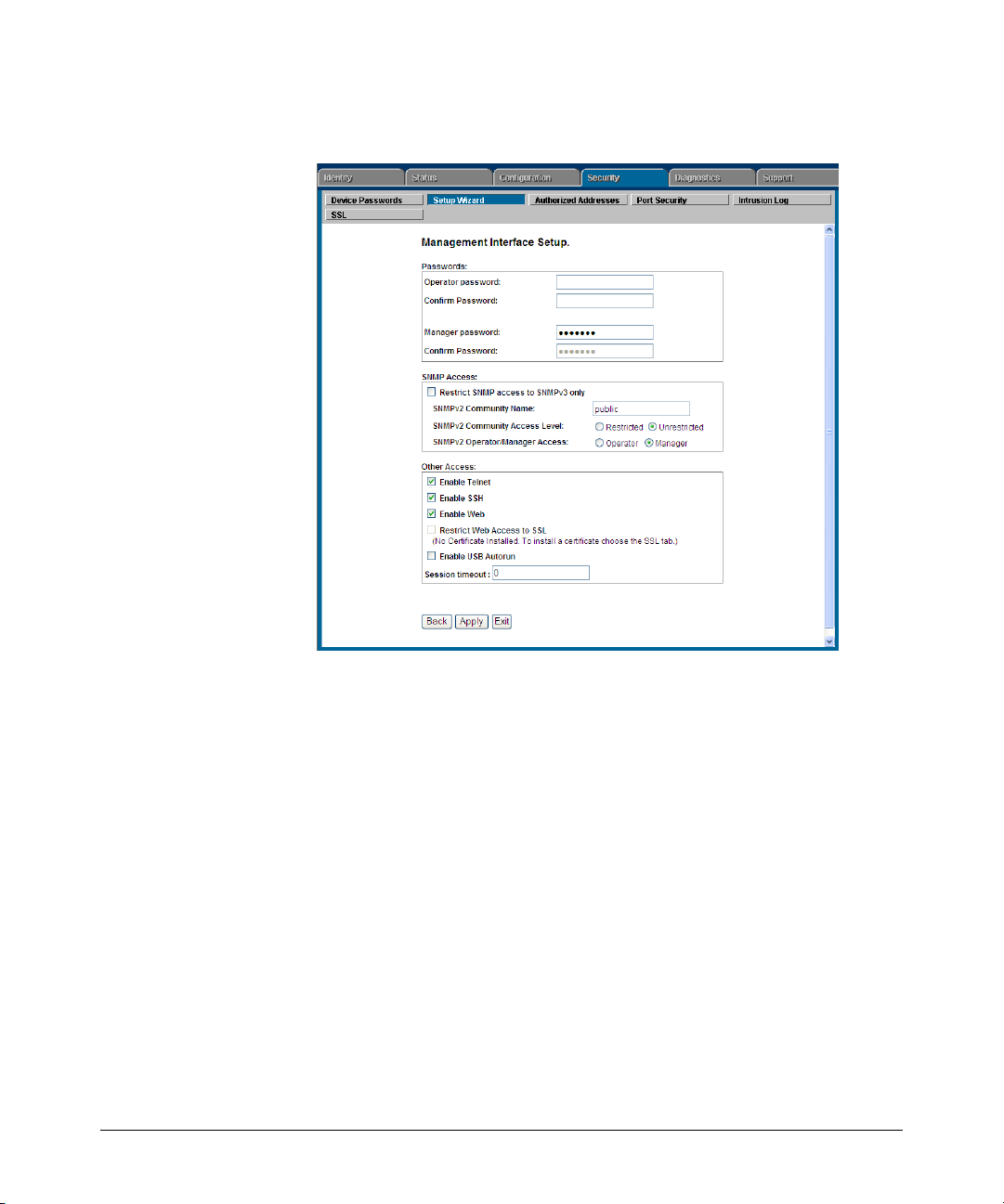
Getting Started with Access Security
Security Overview
4. The summary setup screen displays the current configuration settings for
all setup options (see Figure 1-3).
Figure 1-3. Management Interface Wizard: Summary Setup
From this screen, you have the following options:
• To change any setting that is shown, type in a new value or make a
different selection.
• To apply the settings permanently, click Apply.
• To quit the Setup screen without saving any changes, click Exit.
• To return to the previous screen, click Back.
Web Wizar d: Operating Notes and Restrictions.
■ If you click on the Web interface’s navigation tab during setup, all
configuration changes will be lost.
■ If an Operator or Manager password has been configured on the switch,
the enable USB Autorun option is not available.
■ When you restrict SNMP access to SNMPv3 only, the SNMPv2 options are
not available.
■ The option to restrict Web Access to SSL is made available only if a server
certificate has been previously installed on the switch.
1-15
Page 42

Security Overview
Getting Started with Access Security
SNMP Security Guidelines
In the default configuration, the switch is open to access by management
stations running SNMP (Simple Network Management Protocol) management
applications capable of viewing and changing the settings and status data in
the switch’s MIB (Management Information Base). Thus, controlling SNMP
access to the switch and preventing unauthorized SNMP access should be a
key element of your network security strategy.
General SNMP Access to the Switch. The switch supports SNMP
versions 1, 2c, and 3, including SNMP community and trap configuration. The
default configuration supports versions 1 and 2c compatibility, which uses
plain text and does not provide security options.
ProCurve recommends that you enable SNMP version 3 for improved security.
SNMPv3 includes the ability to configure restricted access and to block all
non-version 3 messages (which blocks version 1 and 2c unprotected
operation).
SNMPv3 security options include:
■ configuring device communities as a means for excluding management
access by unauthorized stations
■ configuring for access authentication and privacy
■ reporting events to the switch CLI and to SNMP trap receivers
■ restricting non-SNMPv3 agents to either read-only access or no access
■ co-existing with SNMPv1 and v2c if necessary
SNMP Access to the Authentication Configuration MIB. A
management station running an SNMP networked device management
application, such as ProCurve Manager Plus (PCM+) or HP OpenView, can
access the switch’s management information base (MIB) for read access to
the switch’s status and read/write access to the switch’s authentication
configuration (hpSwitchAuth). This means that the switch’s default
configuration now allows SNMP access to security settings in hpSwitchAuth.
Note on SNMP This software version enables SNMP access to the authentication
Access to
Authentication
MIB
1-16
configuration MIB (the default action). If SNMPv3 and other security
safeguards are not in place, the switch’s authentication configuration MIB is
exposed to unprotected SNMP access and you should use the command
shown below to disable this access.
Page 43

Getting Started with Access Security
Security Overview
If SNMP access to the hpSwitchAuth MIB is considered a security risk
in your network, then you should implement the following security
precautions:
■ If SNMP access to the authentication configuration (hpSwitchAuth) MIB
described above is not desirable for your network, use the following
command to disable this feature:
snmp-server mib hpswitchauthmib excluded
■ If you choose to leave the authentication configuration MIB accessible,
then you should do the following to help ensure that unauthorized workstations cannot use SNMP tools to access the MIB:
a. Configure SNMP version 3 management and access security on the
switch.
b. Disable SNMP version 2c on the switch.
For details on this feature, refer to the section titled “Using SNMP To View
and Configure Switch Authentication Features” on page 5-21.
For more information on configuring SNMP, refer to the section “Using SNMP
Tools To Manage the Switch” in the chapter “Configuring for Network
Management Applications” in the Management and Configuration Guide
for your switch.
1-17
Page 44

Security Overview
Precedence of Security Options
Precedence of Security Options
This section explains how port-based security options, and client-based
attributes used for authentication, get prioritized on the switch.
Precedence of Port-Based Security Options
Where the switch is running multiple security options, it implements network
traffic security based on the OSI (Open Systems Interconnection model)
precedence of the individual options, from the lowest to the highest. The
following list shows the order in which the switch implements configured
security features on traffic moving through a given port.
1. Disabled/Enabled physical port
2. MAC lockout (Applies to all ports on the switch.)
3. MAC lockdown
4. Port security
5. Authorized IP Managers
6. Application features at higher levels in the OSI model, such as SSH.
(The above list does not address the mutually exclusive relationship that
exists among some security features.)
Precedence of Client-Based Authentication: Dynamic Configuration Arbiter
The Dynamic Configuration Arbiter (DCA) is implemented to determine the
client-specific parameters that are assigned in an authentication session.
A client-specific authentication configuration is bound to the MAC address of
a client device and may include the following parameters:
■ Untagged client VLAN ID
■ Tagged VLAN IDs
■ Per-port CoS (802.1p) priority
■ Per-port rate-limiting on inbound traffic
■ Client-based ACLs
1-18
Page 45

Precedence of Security Options
DCA allows client-specific parameters configured in any of the following ways
to be applied and removed as needed in a specified hierarchy of precedence.
When multiple values for an individual configuration parameter exist, the
value applied to a client session is determined in the following order (from
highest to lowest priority) in which a value configured with a higher priority
overrides a value configured with a lower priority:
1. Attribute profiles applied through the Network Immunity network-management application using SNMP (see “Network Immunity Manager”)
2. 802.1X authentication parameters (RADIUS-assigned)
3. Web- or MAC-authentication parameters (RADIUS-assigned)
4. Local, statically-configured parameters
Although RADIUS-assigned settings are never applied to ports for nonauthenticated clients, the Dynamic Configuration Arbiter allows you to
configure and assign client-specific port configurations to non-authenticated
clients, provided that a client’s MAC address is known in the switch in the
forwarding database. DCA arbitrates the assignment of attributes on both
authenticated and non-authenticated ports.
DCA does not support the arbitration and assignment of client-specific
attributes on trunk ports.
Security Overview
Network Immunity Manager
Network Immunity Manager (NIM) is a plug-in to ProCurve Manager (PCM)
and a key component of the ProCurve Network Immunity security solution
that provides comprehensive detection and per-port-response to malicious
traffic at the ProCurve network edge. NIM allows you to apply policy-based
actions to minimize the negative impact of a client’s behavior on the network.
For example, using NIM you can apply a client-specific profile that adds or
modifies per-port rate-limiting and VLAN ID assignments.
Note NIM actions only support the configuration of per-port rate-limiting and VLAN
ID assignment; NIM does not support CoS (802.1p) priority assignment and
ACL configuration.
NIM-applied parameters temporarily override RADIUS-configured and locally
configured parameters in an authentication session. When the NIM-applied
action is removed, the previously applied client-specific parameter (locally
configured or RADIUS-assigned) is re-applied unless there have been other
configuration changes to the parameter. In this way, NIM allows you to
minimize network problems without manual intervention.
1-19
Page 46

Security Overview
Precedence of Security Options
NIM also allows you to configure and apply client-specific profiles on ports
that are not configured to authenticate clients (unauthorized clients), provided
that a client’s MAC address is known in the switch’s forwarding database.
The profile of attributes applied for each client (MAC address) session is
stored in the hpicfUsrProfile MIB, which serves as the configuration interface
for Network Immunity Manager. A client profile consists of NIM-configured,
RADIUS-assigned, and statically configured parameters. Using show
commands for 802.1X, web or MAC authentication, you can verify which
RADIUS -assigned and statically configured parameters are supported and if
they are supported on a per-port or per-client basis.
A NIM policy accesses the hpicfUsrProfileMIB through SNMP to perform the
following actions:
■ Bind (or unbind) a profile of configured attributes to the MAC address of
■ Configure or unconfigure an untagged VLAN for use in an authenticated
Note that the attribute profile assigned to a client is often a combination of
NIM-configured, RADIUS-assigned, and statically configured settings.
Precedence is always given to the temporarily applied NIM-configured
parameters over RADIUS-assigned and locally configured parameters.
a client device on an authenticated or unauthenticated port.
or unauthenticated client session.
1-20
For information on Network Immunity Manager, go to the HP ProCurve
Networking Web site at www.procurve.com/solutions, click on Security, and
then click on Security Products.
Arbitrating Client-Specific Attributes
In previous releases, client-specific authentication parameters for 802.1X
Web, and MAC authentication are assigned to a port using different criteria.
A RADIUS-assigned parameter is always given highest priority and overrides
statically configured local passwords. 802.1X authentication parameters
override Web or MAC authentication parameters.
DCA stores three levels of client-specific authentication parameters and
prioritizes them according to the following hierarchy of precedence:
1. NIM access policy (applied through SNMP)
2. RADIUS-assigned
a. 802.1X authentication
b. Web or MAC authentication
3. Statically (local) configured
Page 47

Precedence of Security Options
Security Overview
Client-specific configurations are applied on a per-parameter basis on a port.
In a client-specific profile, if DCA detects that a parameter has configured
values from two or more levels in the hierarchy of precedence described
above, DCA decides which parameters to add or remove, or whether to fail
the authentication attempt due to an inability to apply the parameters.
For example, NIM may configure only rate-limiting for a specified client
session, while RADIUS-assigned values may include both an untagged VLAN
ID and a rate-limiting value to be applied. In this case, DCA applies the NIMconfigured rate-limiting value and the RADIUS-assigned VLAN (if there are no
other conflicts).
Also, you can assign NIM-configured parameters (for example, VLAN ID
assignment or rate-limiting) to be activated in a client session when a threat
to network security is detected. When the NIM-configured parameters are
later removed, the parameter values in the client session return to the
RADIUS-configured or locally configured settings, depending on which are
next in the hierarchy of precedence.
In addition, DCA supports conflict resolution for QoS (port-based CoS
priority) and rate-limiting (ingress) by determining whether to configure
either strict or non-strict resolution on a switch-wide basis. For example, if
multiple clients authenticate on a port and a rate-limiting assignment by a
newly authenticating client conflicts with the rate-limiting values assigned to
previous clients, by using Network Immunity you can configure the switch to
apply any of the following attributes:
■ Apply only the latest rate-limiting value assigned to all clients.
■ Apply a client-specific rate-limiting configuration to the appropriate client
session (overwrites any rate-limit previously configured for other client
sessions on the port).
For information about how to configure RADIUS-assigned and locally
configured authentication settings, refer to:
■ RADIUS-assigned 802.1X authentication: “Configuring Port-Based and
User-Based Access Control (802.1X)” on page 12-1.
■ RADIUS-assigned Web or MAC authentication: “Web and MAC Authenti-
cation” on page 3-1.
■ RADIUS-assigned CoS, rate-limiting, and ACLS: “Configuring RADIUS
Server Support for Switch Services” on page 6-1.
■ Statically (local) configured: “Configuring Username and Password
Security” on page 2-1.
1-21
Page 48

Security Overview
ProCurve Identity-Driven Manager (IDM)
ProCurve Identity-Driven Manager
(IDM)
IDM is a plug-in to ProCurve Manager Plus (PCM+) and uses RADIUS-based
technologies to create a user-centric approach to network access
management and network activity tracking and monitoring. IDM enables
control of access security policy from a central management server, with
policy enforcement to the network edge, and protection against both external
and internal threats.
Using IDM, a system administrator can configure automatic and dynamic
security to operate at the network edge when a user connects to the network.
This operation enables the network to:
■ approve or deny access at the edge of the network instead of in the core;
■ distinguish among different users and what each is authorized to do;
■ configure guest access without compromising internal security.
Criteria for enforcing RADIUS-based security for IDM applications includes
classifiers such as:
■ authorized user identity
■ authorized device identity (MAC address)
■ software running on the device
■ physical location in the network
■ time of day
1-22
Responses can be configured to support the networking requirements, user
(SNMP) community, service needs, and access security level for a given client
and device.
For more information on IDM, go to the ProCurve Web site at
www.procurve.com/solutions, click on Security, and then click Security Products.
Page 49

Configuring Username and Password Security
Contents
Overview . . . . . . . . . . . . . . . . . . . . . . . . . . . . . . . . . . . . . . . . . . . . . . . . . . . . . 2-3
Configuring Local Password Security . . . . . . . . . . . . . . . . . . . . . . . . . . . 2-6
Menu: Setting Passwords . . . . . . . . . . . . . . . . . . . . . . . . . . . . . . . . . . . . . 2-6
CLI: Setting Passwords and Usernames . . . . . . . . . . . . . . . . . . . . . . . . . 2-8
Web: Setting Passwords and Usernames . . . . . . . . . . . . . . . . . . . . . . . . 2-9
SNMP: Setting Passwords and Usernames . . . . . . . . . . . . . . . . . . . . . . 2-9
Saving Security Credentials in a
Config File . . . . . . . . . . . . . . . . . . . . . . . . . . . . . . . . . . . . . . . . . . . . . . . . . . . 2-10
Benefits of Saving Security Credentials . . . . . . . . . . . . . . . . . . . . . . . . 2-10
Enabling the Storage and Display of Security Credentials . . . . . . . . 2-11
Security Settings that Can Be Saved . . . . . . . . . . . . . . . . . . . . . . . . . . . 2-11
Local Manager and Operator Passwords . . . . . . . . . . . . . . . . . . . . . . . 2-12
Password Command Options . . . . . . . . . . . . . . . . . . . . . . . . . . . . . . . . 2-13
SNMP Security Credentials . . . . . . . . . . . . . . . . . . . . . . . . . . . . . . . . . . 2-14
802.1X Port-Access Credentials . . . . . . . . . . . . . . . . . . . . . . . . . . . . . . . 2-15
TACACS+ Encryption Key Authentication . . . . . . . . . . . . . . . . . . . . . 2-15
RADIUS Shared-Secret Key Authentication . . . . . . . . . . . . . . . . . . . . 2-16
SSH Client Public-Key Authentication . . . . . . . . . . . . . . . . . . . . . . . . . 2-16
Operating Notes . . . . . . . . . . . . . . . . . . . . . . . . . . . . . . . . . . . . . . . . . . . . 2-19
Restrictions . . . . . . . . . . . . . . . . . . . . . . . . . . . . . . . . . . . . . . . . . . . . . . . 2-21
2
Front-Panel Security . . . . . . . . . . . . . . . . . . . . . . . . . . . . . . . . . . . . . . . . . 2-23
When Security Is Important . . . . . . . . . . . . . . . . . . . . . . . . . . . . . . . . . . 2-23
Front-Panel Button Functions . . . . . . . . . . . . . . . . . . . . . . . . . . . . . . . . 2-24
Clear Button . . . . . . . . . . . . . . . . . . . . . . . . . . . . . . . . . . . . . . . . . . . 2-24
Reset Button . . . . . . . . . . . . . . . . . . . . . . . . . . . . . . . . . . . . . . . . . . . 2-25
Restoring the Factory Default Configuration . . . . . . . . . . . . . . . . 2-25
Configuring Front-Panel Security . . . . . . . . . . . . . . . . . . . . . . . . . . . . . 2-26
2-1
Page 50

Configuring Username and Password Security
Contents
Disabling the Clear Password Function of the Clear Button
on the Switch’s Front Panel . . . . . . . . . . . . . . . . . . . . . . . . . . . . . . 2-29
Re-Enabling the Clear Button on the Switch’s Front Panel
and Setting or Changing the “Reset-On-Clear” Operation . . . . . 2-30
Changing the Operation of the Reset+Clear Combination . . . . . 2-31
Password Recovery . . . . . . . . . . . . . . . . . . . . . . . . . . . . . . . . . . . . . . . . . 2-32
Disabling or Re-Enabling the Password Recovery Process . . . . 2-32
Password Recovery Process . . . . . . . . . . . . . . . . . . . . . . . . . . . . . . . . . 2-34
2-2
Page 51

Configuring Username and Password Security
Overview
Overview
Feature Default Menu CLI Web
Set Usernames none — — page 2-9
Set a Password none page 2-6 page 2-8 page 2-9
Delete Password Protection n/a page 2-7 page 2-8 page 2-9
show front-panel-security
front-panel-security
password-clear
reset-on-clear
factory-reset
password-recovery
Console access includes both the menu interface and the CLI. There are two
levels of console access: Manager and Operator. For security, you can set a
password pair (username and password) on each of these levels.
n/a — page 1-13 —
— page 1-13 —
enabled — page 1-13 —
disabled — page 1-14 —
enabled — page 1-15 —
enabled — page 1-15 —
Notes Usernames are optional. Also, in the menu interface, you can configure
passwords, but not usernames. To configure usernames, use the CLI or the
web browser interface.
Usernames and passwords for Manager and Operator access can also be
configured using SNMP. For more information, refer to “Using SNMP To View
and Configure Switch Authentication Features” on page 5-21.
Beginning with software release W.14.xx, usernames and passwords for Manager and Operator access can also be configured using the Management
Interface Wizard. For more information, refer to “Quick Start: Using the
Management Interface Wizard” on page 1-11.
2-3
Page 52

Configuring Username and Password Security
Overview
Level Actions Permitted
Manager: Access to all console interface areas.
This is the default level. That is, if a Manager password has not been set prior
to starting the current console session, then anyone having access to the
console can access any area of the console interface.
Operator: Access to the Status and Counters menu, the Event Log, and the CLI*, but no
Configuration capabilities.
On the Operator level, the configuration menus, Download OS, and Reboot
Switch options in the Main Menu are not available.
*Allows use of the ping, link-test, show, menu, exit, and logout commands, plus the enable
command if you can provide the Manager password.
To configure password security:
1. Set a Manager password pair (and an Operator password pair, if applicable
for your system).
2. Exit from the current console session. A Manager password pair will now
be needed for full access to the console.
2-4
If you do steps 1 and 2, above, then the next time a console session is started
for either the menu interface or the CLI, a prompt appears for a password.
Assuming you have protected both the Manager and Operator levels, the level
of access to the console interface will be determined by which password is
entered in response to the prompt.
If you set a Manager password, you may also want to configure an inactivity
timer. This causes the console session to end after the specified period of
inactivity, thus giving you added security against unauthorized console access.
You can use either of the following to set the inactivity timer:
■ Menu Interface: System Information screen (Select “2. Switch Configu-
ration.)
■ CLI: Use the console inactivity-timer < 0 | 1 | 5 | 10 | 15 | 20 | 30 | 60 | 120 >
Page 53

Configuring Username and Password Security
Overview
Notes The manager and operator passwords and (optional) usernames control
access to the menu interface, CLI, and web browser interface.
If you configure only a Manager password (with no Operator password), and
in a later session the Manager password is not entered correctly in response
to a prompt from the switch, then the switch does not allow management
access for that session.
If the switch has a password for both the Manager and Operator levels, and
neither is entered correctly in response to the switch’s password prompt, then
the switch does not allow management access for that session.
Passwords are case-sensitive.
When configuring an operator or manager password a message will appear
indicating that (USB) autorun has been disabled. For more information on the
autorun feature, refer to the Appendix A on “File Transfers” in the Manage-
ment and Configuration Guide for your switch.
Caution If the switch has neither a Manager nor an Operator password, anyone
having access to the switch through either Telnet, the serial port, or the web
browser interface can access the switch with full manager privileges. Also,
if you configure only an Operator password, entering the Operator password enables full manager privileges.
The rest of this chapter covers how to:
■ Set passwords
■ Delete passwords
■ Recover from a lost password
■ Maintain front-panel security
2-5
Page 54

Configuring Username and Password Security
Configuring Local Password Security
Configuring Local Password Security
Menu: Setting Passwords
As noted earlier in this section, usernames are optional. Configuring a username requires either the CLI or the web browser interface.
1. From the Main Menu select:
3. Console Passwords
2-6
Figure 2-1. The Set Password Screen
2. To set a new password:
a. Select Set Manager Password or Set Operator Password. You will then
be prompted with Enter new password.
b. Type a password of up to 16 ASCII characters with no spaces and
press [Enter]. (Remember that passwords are case-sensitive.)
c. When prompted with Enter new password again, retype the new pass-
word and press [Enter].
After you configure a password, if you subsequently start a new console
session, you will be prompted to enter the password. (If you use the CLI or
web browser interface to configure an optional username, the switch will
prompt you for the username, and then the password.)
Page 55

Configuring Username and Password Security
Configuring Local Password Security
To Delete Password Protection (Including Recovery from a Lost
Password): This procedure deletes all usernames (if configured) and pass-
words (Manager and Operator).
If you have physical access to the switch, press and hold the Clear button (on
the front of the switch) for a minimum of one second to clear all password
protection, then enter new passwords as described earlier in this chapter.
If you do not have physical access to the switch, you will need Manager-Level
access:
1. Enter the console at the Manager level.
2. Go to the Set Passwords screen as described above.
3. Select Delete Password Protection. You will then see the following prompt:
Continue Deletion of password protection? No
4. Press the Space bar to select Yes , then press [Enter].
5. Press [Enter] to clear the Password Protection message.
To Recover from a Lost Manager Password: If you cannot start a console session at the Manager level because of a lost Manager password, you
can clear the password by getting physical access to the switch and pressing
and holding the Clear button for a minimum of one second. This action deletes
all passwords and usernames (Manager and Operator) used by both the
console and the web browser interface.
2-7
Page 56

Configuring Username and Password Security
Configuring Local Password Security
CLI: Setting Passwords and Usernames
Commands Used in This Section
password See below.
Configuring Manager and Operator Passwords.
Note The password command has changed. You can now configure manager and
operator passwords in one step. See “Saving Security Credentials in a Config
File” on page 2-10 of this guide.
Syntax: [ no ] password <manager | operator | all | port-access>
[ user-name ASCII-STR ] [<plaintext | sha1> ASCII-STR]
• Password entries appear
as asterisks.
• You must type the
password entry twice.
Figure 2-2. Example of Configuring Manager and Operator Passwords
To Remove Password Protection. Removing password protection means
to eliminate password security. This command prompts you to verify that you
want to remove one or both passwords, then clears the indicated password(s).
(This command also clears the username associated with a password you are
removing.) For example, to remove the Operator password (and username, if
assigned) from the switch, you would do the following:
Press [Y] (for yes) and press [Enter].
Figure 2-3. Removing a Password and Associated Username from the Switch
The effect of executing the command in figure 2-3 is to remove password
protection from the Operator level. (This means that anyone who can access
the switch console can gain Operator access without having to enter a username or password.)
2-8
Page 57

Configuring Username and Password Security
If you want to remove both operator and manager password protection, use
the no password all command.
Configuring Local Password Security
Web: Setting Passwords and Usernames
In the web browser interface you can enter passwords and (optional) usernames.
To Configure (or Remove) Usernames and Passwords in the Web
Browser Interface.
1. Click on the
Click on
2. Do one of the following:
3. Implement the usernames and passwords by clicking on
[Device Passwords].
• To set username and password protection, enter the usernames and
passwords you want in the appropriate fields.
• To remove username and password protection, leave the fields blank.
Security tab.
[Apply Changes].
SNMP: Setting Passwords and Usernames
Usernames and passwords for Manager and Operator access can also be
configured using SNMP. For more information, refer to “Using SNMP To View
and Configure Switch Authentication Features” on page 5-21.
2-9
Page 58

Configuring Username and Password Security
Saving Security Credentials in a Config File
Saving Security Credentials in a
Config File
You can store and view the following security settings in the running-config
file associated with the current software image by entering the include-
credentials command (formerly this information was stored only in internal
flash memory):
■ Local manager and operator passwords and (optional) user names that
control access to a management session on the switch through the CLI,
menu interface, or web browser interface
■ SNMP security credentials used by network management stations to
access a switch, including authentication and privacy passwords
■ Port-access passwords and usernames used as 802.1X authentication
credentials for access to the switch
■ TACACS+ encryption keys used to encrypt packets and secure
authentication sessions with TACACS+ servers
■ RADIUS shared secret (encryption) keys used to encrypt packets and
secure authentication sessions with RADIUS servers
■ Secure Shell (SSH) public keys used to authenticate SSH clients that try
to connect to the switch.
2-10
Benefits of Saving Security Credentials
The benefits of including and saving security credentials in a configuration
file are as follows:
■ After making changes to security parameters in the running configuration,
you can experiment with the new configuration and, if necessary, view
the new security settings during the session. After verifying the
configuration, you can then save it permanently by writing the settings to
the startup-config file.
■ By permanently saving a switch’s security credentials in a configuration
file, you can upload the file to a TFTP server or Xmodem host, and later
download the file to the ProCurve switches on which you want to use the
same security settings without having to manually configure the settings
(except for SNMPv3 user parameters) on each switch.
Page 59

Configuring Username and Password Security
Saving Security Credentials in a Config File
■ By storing different security settings in different files, you can test
different security configurations when you first download a new software
version that supports multiple configuration files, by changing the
configuration file used when you reboot the switch.
For more information about how to experiment with, upload, download, and
use configuration files with different software versions, refer to the following:
■ The chapter on “Switch Memory and Configuration” in the Management
and Configuration Guide.
■ “Configuring Local Password Security” on page 2-6 in this guide.
Enabling the Storage and Display of Security Credentials
To enable the security settings, enter the include-credentials command.
Syntax: [no] include-credentials
Enables the inclusion and display of the currently configured
manager and operator usernames and passwords, RADIUS shared
secret keys, SNMP and 802.1X authenticator (port-access) security
credentials, and SSH client public-keys in the running
configuration. (Earlier software releases store these security
configuration settings only in internal flash memory and do not
allow you to include and view them in the running-config file.)
To view the currently configured security settings in the running
configuration, enter one of the following commands:
■ show running-config: Displays the configuration settings in the
current running-config file.
■ write terminal: Displays the configuration settings in the current
running-config file.
For more information, refer to “Switch Memory and
Configuration” in the Management and Configuration Guide.
The “no” form of the command disables only the display and copying
of these security parameters from the running configuration, while
the security settings remain active in the running configuration.
Default: The security credentials described in “Security Settings
that Can Be Saved” on page 2-11 are not stored in the running
configuration.
Security Settings that Can Be Saved
The security settings that can be saved to a configuration file are:
■ Local manager and operator passwords and user names
2-11
Page 60

Configuring Username and Password Security
Saving Security Credentials in a Config File
■ SNMP security credentials, including SNMPv1 community names and
SNMPv3 usernames, authentication, and privacy settings
■ 802.1X port-access passwords and usernames
■ TACACS+ encryption keys
■ RADIUS shared secret (encryption) keys
■ Public keys of SSH-enabled management stations that are used by the
switch to authenticate SSH clients that try to connect to the switch
Local Manager and Operator Passwords
The information saved to the running-config file when the include-credentials
command is entered includes:
password manager [user-name <name>] <hash-type> <pass-hash>
password operator [user-name <name>] <hash-type> <pass-hash>
where
<name> is an alphanumeric string for the user name assigned to the
manager or operator.
<hash-type> indicates the type of hash algorithm used: SHA-1 or plain
text.
<pass-hash> is the SHA-1 authentication protocol’s hash of the password or clear ASCII text.
For example, a manager username and password may be stored in a runningconfig file as follows:
password manager user-name George SHA1
2fd4e1c67a2d28fced849ee1bb76e7391b93eb12
Use the write memory command to save the password configurations in the
startup-config file. The passwords take effect when the switch boots with the
software version associated with that configuration file.
Caution If a startup configuration file includes other security credentials, but does not
contain a manager or operator password, the switch will not have password
protection and can be accessed through Telnet, the serial port, or web
interface with full manager privileges.
2-12
Page 61

Configuring Username and Password Security
Saving Security Credentials in a Config File
Password Command Options
The password command has the following options:
Syntax: [no] password <manager | operator | port-access| all [user-name <name>]
<hash-type> <password>>
Set or clear a local username/password for a given access level.
manager: configures access to the switch with manager-level
privileges.
operator: configures access to the switch with operator-level
privileges.
port-access: configures access to the switch through 802.1X
authentication with operator-level privileges.
user-name <name>: the optional text string of the user name
associated with the password.
all: configures all available types of access.
<hash-type>: specifies the type of algorithm (if any) used to
hash the password. Valid values are plaintext or sha-1
<password>: the clear ASCII text string or SHA-1 hash of the
password.
You can enter a manager, operator, or 802.1X port-access password in clear
ASCII text or hashed format. However, manager and operator passwords are
displayed and saved in a configuration file only in hashed format; port-access
passwords are displayed and saved only as plain ASCII text.
After you enter the complete command syntax, the password is set. You are
not prompted to enter the password a second time.
This command enhancement allows you to configure manager, operator, and
802.1X port-access passwords in only one step (instead of entering the
password command and then being prompted twice to enter the actual
password).
■ For more information about configuring local manager and operator
passwords, refer to “Configuring Username and Password Security” on
page 2-1 in this guide.
■ For more information about configuring a port-access password for
802.1X client authentication, see “802.1X Port-Access Credentials” on
page 2-15 in this guide.
2-13
Page 62

Configuring Username and Password Security
Saving Security Credentials in a Config File
SNMP Security Credentials
SNMPv1 community names and write-access settings, and SNMPv3
usernames continue to be saved in the running configuration file even when
you enter the include-credentials command.
In addition, the following SNMPv3 security parameters are also saved:
snmpv3 user “<name>" [auth <md5|sha> “<auth-pass>”]
[priv “<priv-pass>"]
where:
<name> is the name of an SNMPv3 management station.
[auth <md5 | sha>] is the (optional) authentication method used for the
management station.
<auth-pass> is the hashed authentication password used with the
configured authentication method.
[priv <priv-pass>] is the (optional) hashed privacy password used by a
privacy protocol to encrypt SNMPv3 messages between the switch and the
station.
The following example shows the additional security credentials for SNMPv3
users that can be saved in a running-config file:
snmpv3 user boris \
auth md5 “9e4cfef901f21cf9d21079debeca453” \
priv “82ca4dc99e782db1a1e914f5d8f16824”
2-14
snmpv3 user alan \
auth sha “8db06202b8f293e9bc0c00ac98cf91099708ecdf” \
priv “5bc4313e9fd7c2953aaea9406764fe8bb629a538”
Figure 2-4. Example of Security Credentials Saved in the Running-Config
Although you can enter an SNMPv3 authentication or privacy password in
either clear ASCII text or the SHA-1 hash of the password, the password is
displayed and saved in a configuration file only in hashed format, as shown in
the preceding example.
For more information about the configuration of SNMP security parameters,
refer to the chapter on “Configuring for Network Management Applications”
in the Management and Configuration Guide for your switch.
Page 63

Configuring Username and Password Security
Saving Security Credentials in a Config File
802.1X Port-Access Credentials
802.1X authenticator (port-access) credentials can be stored in a
configuration file. 802.1X authenticator credentials are used by a port to
authenticate supplicants requesting a point-to-point connection to the switch.
802.1X supplicant credentials are used by the switch to establish a point-topoint connection to a port on another 802.1X-aware switch. Only 802.1X
authenticator credentials are stored in a configuration file. For information
about how to use 802.1X on the switch both as an authenticator and a
supplicant, see “Configuring Port-Based and Client-Based Access Control
(802.1X)” in this guide.
The local password configured with the password command is no longer
accepted as an 802.1X authenticator credential. A new configuration
command (password port-access) is introduced to configure the local operator
username and password used as 802.1X authentication credentials for access
to the switch.
The password port-access values are now configured separately from the
manager and operator passwords configured with the password manager and
password operator commands and used for management access to the switch.
For information on the new password command syntax, see “Password
Command Options” on page 2-13.
After you enter the complete password port-access command syntax, the
password is set. You are not prompted to enter the password a second time.
TACACS+ Encryption Key Authentication
You can use TACACS+ servers to authenticate users who request access to a
switch through Telnet (remote) or console (local) sessions. TACACS+ uses an
authentication hierarchy consisting of:
■ Remote passwords assigned in a TACACS+ server
■ Local manager and operator passwords configured on the switch.
When you configure TACACS+, the switch first tries to contact a designated
TACACS+ server for authentication services. If the switch fails to connect to
any TACACS+ server, it defaults to its own locally assigned passwords for
authentication control if it has been configured to do so.
For improved security, you can configure a global or server-specific
encryption key that encrypts data in TACACS+ packets transmitted between
a switch and a RADIUS server during authentication sessions. The key
configured on the switch must match the encryption key configured in each
2-15
Page 64

Configuring Username and Password Security
Saving Security Credentials in a Config File
TACACS+ server application. (The encryption key is sometimes referred to as
“shared secret” or “secret” key.) For more information, see “TACACS+
Authentication” on page 4-1 in this guide.
TACACS+ shared secret (encryption) keys can be saved in a configuration file
by entering this command:
ProCurve(config)# tacacs-server key <keystring>
The option <keystring> is the encryption key (in clear text) used for secure
communication with all or a specific TACACS+ server.
RADIUS Shared-Secret Key Authentication
You can use RADIUS servers as the primary authentication method for users
who request access to a switch through Telnet, SSH, Web interface, console,
or port-access (802.1X). The shared secret key is a text string used to encrypt
data in RADIUS packets transmitted between a switch and a RADIUS server
during authentication sessions. Both the switch and the server have a copy of
the key; the key is never transmitted across the network. For more
information, refer to “3. Configure the Switch To Access a RADIUS Server” on
page 5-15 in this guide.
RADIUS shared secret (encryption) keys can be saved in a configuration file
by entering this command:
ProCurve(config)# radius-server key <keystring>
The option <keystring> is the encryption key (in clear text) used for secure
communication with all or a specific RADIUS server.
SSH Client Public-Key Authentication
Secure Shell version 2 (SSHv2) is used by ProCurve switches to provide
remote access to SSH-enabled management stations. Although SSH provides
Telnet-like functions, unlike Telnet, SSH provides encrypted, two-way
authenticated transactions. SSH client public-key authentication is one of the
types of authentication used.
Client public-key authentication uses one or more public keys (from clients)
that must be stored on the switch. Only a client with a private key that matches
a public key stored on the switch can gain access at the manager or operator
level. For more information about how to configure and use SSH public keys
to authenticate SSH clients that try to connect to the switch, refer to
“Configuring Secure Shell (SSH)” on page 7-1 in this guide.
2-16
Page 65

Configuring Username and Password Security
Saving Security Credentials in a Config File
The SSH security credential that is stored in the running configuration file is
configured with the ip ssh public-key command used to authenticate SSH
clients for manager or operator access, along with the hashed content of each
SSH client public-key.
Syntax: ip ssh public-key <manager |operator> keystring
Set a key for public-key authentication.
manager: allows manager-level access using SSH public-key
authentication.
operator: allows operator-level access using SSH public-key
authentication.
“keystring”:. a legal SSHv2 (RSA or DSA) public key. The text
string for the public key must be a single quoted token. If the
keystring contains double-quotes, it can be quoted with single
quotes ('keystring'). The following restrictions for a
keystring apply:
■ A keystring cannot contain both single and double quotes.
■ A keystring cannot have extra characters, such as a blank
space or a new line. However, to improve readability, you
can add a backlash at the end of each line.
Note The ip ssh public-key command allows you to configure only one SSH client
public-key at a time. The ip ssh public-key command behavior includes an
implicit append that never overwrites existing public-key configurations on a
running switch.
If you download a software configuration file that contains SSH client publickey configurations, the downloaded public-keys overwrite any existing keys,
as happens with any other configured values.
2-17
Page 66

Configuring Username and Password Security
Saving Security Credentials in a Config File
To display the SSH public-key configurations (72 characters per line) stored
in a configuration file, enter the show config or show running-config command.
The following example shows the SSH public keys configured for manager
access, along with the hashed content of each SSH client public-key, that are
stored in a configuration file:
...
include-credentials
ip ssh public-key manager “ssh-dss \
AAAAB3NzaC1kc3MAAACBAPwJHSJmTRtpZ9BUNC+ZrsxhMuZEXQhaDME1vc/ \
EvYnTKxQ31bWvr/bT7W58NX/YJ1ZKTV2GZ2QJCicUUZVWjNFJCsa0v03XS4 \
BhkXjtHhz6gD701otgizUOO6/Xzf4/J9XkJHkOCnbHIqtB1sbRYBTxj3NzA \
K1ymvIaU09X5TDAAAAFQCPwKxnbwFfTPasXnxfvDuLSxaC7wAAAIASBwxUP \
pv2scqPPXQghgaTkdPwGGtdFW/+K4xRskAnIaxuG0qLbnekohi+ND4TkKZd \
EeidgDh7qHusBhOFXM2g73RpE2rNqQnSf/QV95kdNwWIbxuusBAzvfaJptd \
gca6cYR4xS4TuBcaKiorYj60kk144E1fkDWieQx8zABQAAAIEAu7/1kVOdS \
G0vE0eJD23TLXvu94plXhRKCUAvyv2UyK+piG+Q1el1w9zsMaxPA1XJzSY/ \
imEp4p6WXEMcl0lpXMRnkhnuMMpaPMaQUT8NJTNu6hqf/LdQ2kqZjUuIyV9 \
LWyLg5ybS1kFLeOt0oo2Jbpy+U2e4jh2Bb77sX3G5C0= spock@sfc.gov” \
ip ssh public-key manager ‘ssh-rsa \
AAAAB3NzaC1yc2EAAAADAQABAAAAgQDyO9RDD52JZP8k2F2YZXubgwRAN0R \
JRs1Eov6y1RK3XkmgVatzl+mspiEmPS4wNK7bX/IoXNdGrGkoE8tPkxlZOZ \
oqGCf5Zs50P1nkxXvAidFs55AWqOf4MhfCqvtQCe1nt6LFh4ZMig+YewgQG \
M6H1geCSLUbXXSCipdPHysakw== "TectiaClientKey [1024-bit rsa, \
nobody@testmachine, Mon Aug 15 2005 14:47:34]”’
ip ssh public-key manager “ssh-rsa \
AAAAB3NzaC1yc2EAAABIwAAAIEA1Kk9sVQ9LJOR6XO/hCMPxbiMNOK8C/ay \
+SQ10qGw+K9m3w3TmCfjh0ud9hivgbFT4F99AgnQkvm2eVsgoTtLRnfF7uw \
NmpzqOqpHjD9YzItUgSK1uPuFwXMCHKUGKa+G46A+EWxDAIypwVIZ697QmM \
qPFj1zdI4sIo5bDett2d0= joe@hp.com”
...
2-18
Figure 2-5. Example of SSH Public Keys
If a switch configuration contains multiple SSH client public keys, each public
key is saved as a separate entry in the configuration file. You can configure up
to ten SSH client public-keys on a switch.
Page 67

Configuring Username and Password Security
Saving Security Credentials in a Config File
Operating Notes
Caution ■ When you first enter the include-credentials command to save the
additional security credentials to the running configuration, these settings
are moved from internal storage on the switch to the running-config file.
You are prompted by a warning message to perform a write memory
operation to save the security credentials to the startup configuration. The
message reminds you that if you do not save the current values of these
security settings from the running configuration, they will be lost the next
time you boot the switch and will revert to the values stored in the startup
configuration.
■ When you boot a switch with a startup configuration file that contains the
include-credentials command, any security credentials that are stored in
internal flash memory are ignored and erased. The switch will load only
the security settings in the startup configuration file.
■ Security settings are no longer automatically saved internally in flash
memory and loaded with the startup configuration when a switch boots
up. The configuration of all security credentials requires that you use the
write memory command to save them in the startup configuration in order
for them to not be lost when you log off. A warning message reminds you
to permanently save a security setting.
■ After you enter the include-credentials command, the currently configured
manager and operator usernames and passwords, RADIUS shared secret
keys, SNMP and 802.1X authenticator (port-access) security credentials,
and SSH client public-keys are saved in the running configuration.
Use the no include-credentials command to disable the display and copying
of these security parameters from the running configuration (using the
show running-config and copy running-config commands), without disabling
the configured security settings on the switch.
After you enter the include-credentials command, you can toggle between
the non-display and display of security credentials in show and copy
command output by alternately entering the no include-credentials and
include-credentials commands.
■ After you permanently save security configurations to the current startup-
config file using the write memory command, you can view and manage
security settings with the following commands:
• show config: Displays the configuration settings in the current startupconfig file.
2-19
Page 68

Configuring Username and Password Security
Saving Security Credentials in a Config File
• copy config <source-filename> config <target-filename>: Makes a local
copy of an existing startup-config file by copying the contents of the
startup-config file in one memory slot to a new startup-config file in
another, empty memory slot.
• copy config tftp: Uploads a configuration file from the switch to a TFTP
server.
• copy tftp config: Downloads a configuration file from a TFTP server to
the switch.
• copy config xmodem: Uploads a configuration file from the switch to
an Xmodem host.
• copy xmodem config: Downloads a configuration file from an Xmodem
host to the switch.
For more information, see “Transferring Startup-Config Files To or From
a Remote Server” in the Management and Configuration Guide.
■ The switch can store up to three configuration files. Each configuration
file contains its own security credentials and these security configurations
may differ. It is the responsibility of the system administrator to ensure
that the appropriate security credentials are contained in the
configuration file that is loaded with each software image and that all
security credentials in the file are supported.
■ If you have already enabled the storage of security credentials (including
local manager and operator passwords) by entering the includecredentials command, the Reset-on-clear option is disabled. When you
press the Clear button on the front panel, the manager and operator
usernames and passwords are deleted from the running configuration.
However, the switch does not reboot after the local passwords are erased.
(The reset-on-clear option normally reboots the switch when you press
the Clear button.)
2-20
For more information about the Reset-on-clear option and other frontpanel security features, see “Configuring Front-Panel Security” on page
2-26 in this guide.
Page 69

Configuring Username and Password Security
Saving Security Credentials in a Config File
Restrictions
The following restrictions apply when you enable security credentials to be
stored in the running configuration with the include-credentials command:
■ The private keys of an SSH host cannot be stored in the running
configuration. Only the public keys used to authenticate SSH clients can
be stored. An SSH host’s private key is only stored internally, for example,
on the switch or on an SSH client device.
■ SNMPv3 security credentials saved to a configuration file on a switch
cannot be used after downloading the file on a different switch. The
SNMPv3 security parameters in the file are only supported when loaded
on the same switch for which they were configured. This is because when
SNMPv3 security credentials are saved to a configuration file, they are
saved with the engine ID of the switch as shown here:
snmpv3 engine-id 00:00:00:0b:00:00:08:00:09:01:10:01
If you download a configuration file with saved SNMPv3 security credentials on a switch, when the switch loads the file with the current software
version the SNMPv3 engine ID value in the downloaded file must match
the engine ID of the switch in order for the SNMPv3 users to be configured
with the authentication and privacy passwords in the file. (To display the
engine ID of a switch, enter the show snmpv3 engine-id command. To
configure authentication and privacy passwords for SNMPv3 users, enter
the snmpv3 user command.)
If the engine ID in the saved SNMPv3 security settings in a downloaded
configuration file does not match the engine ID of the switch:
• The SNMPv3 users are configured, but without the authentication and
privacy passwords. You must manually configure these passwords on
the switch before the users can have SNMPv3 access with the privileges you want.
• Only the snmpv3 user <user_name> credentials from the SNMPv3
settings in a downloaded configuration file are loaded on the switch,
for example:
snmpv3 user boris
snmpv3 user alan
■ You can store 802.1X authenticator (port-access) credentials in a
configuration file. However, 802.1X supplicant credentials cannot be
stored.
■ The local operator password configured with the password command is
no longer accepted as an 802.1X authenticator credential. A new
configuration command (password port-access) is introduced to configure
2-21
Page 70

Configuring Username and Password Security
Saving Security Credentials in a Config File
the username and password used as 802.1X authentication credentials for
access to the switch. You can store the password port-access values in the
running configuration file by using the include-credentials command.
Note that the password port-access values are configured separately from
local operator username and passwords configured with the password
operator command and used for management access to the switch. For
more information about how to use the password port-access command
to configure operator passwords and usernames for 802.1X authentication, see “Do These Steps Before You Configure 802.1X Operation” on page
12-15 in this guide.
2-22
Page 71

Configuring Username and Password Security
Front-Panel Security
Front-Panel Security
The front-panel security features provide the ability to independently enable
or disable some of the functions of the two buttons located on the front of the
switch for clearing the password (Clear button) or restoring the switch to its
factory default configuration (Reset+Clear buttons together). The ability to
disable Password Recovery is also provided for situations which require a
higher level of switch security.
The front-panel Security features are designed to prevent malicious users
from:
■ Resetting the password(s) by pressing the Clear button
■ Restoring the factory default configuration by using the Reset+Clear
button combination.
■ Gaining management access to the switch by having physical access to
the switch itself
When Security Is Important
Some customers require a high level of security for information. Also, the
Health Insurance Portability and Accountability Act (HIPAA) of 1996 requires
that systems handling and transmitting confidential medical records must be
secure.
It used to be assumed that only system and network administrators would be
able to get access to a network switch because switches were typically placed
in secure locations under lock and key. For some customers this is no longer
true. Others simply want the added assurance that even if someone did
manage to get to the switch that data would still remain secure.
If you do not invoke front-panel security on the switch, user-defined passwords can be deleted by pushing the Clear button on the front panel. This
function exists so that if customers forget the defined passwords they can still
get back into the switch and reset the passwords. This does, however, leave
the switch vulnerable when it is located in an area where non-authorized
people have access to it. Passwords could easily be cleared by pressing the
Clear button. Someone who has physical access to the switch may be able to
erase the passwords (and possibly configure new passwords) and take control
of the switch.
2-23
Page 72
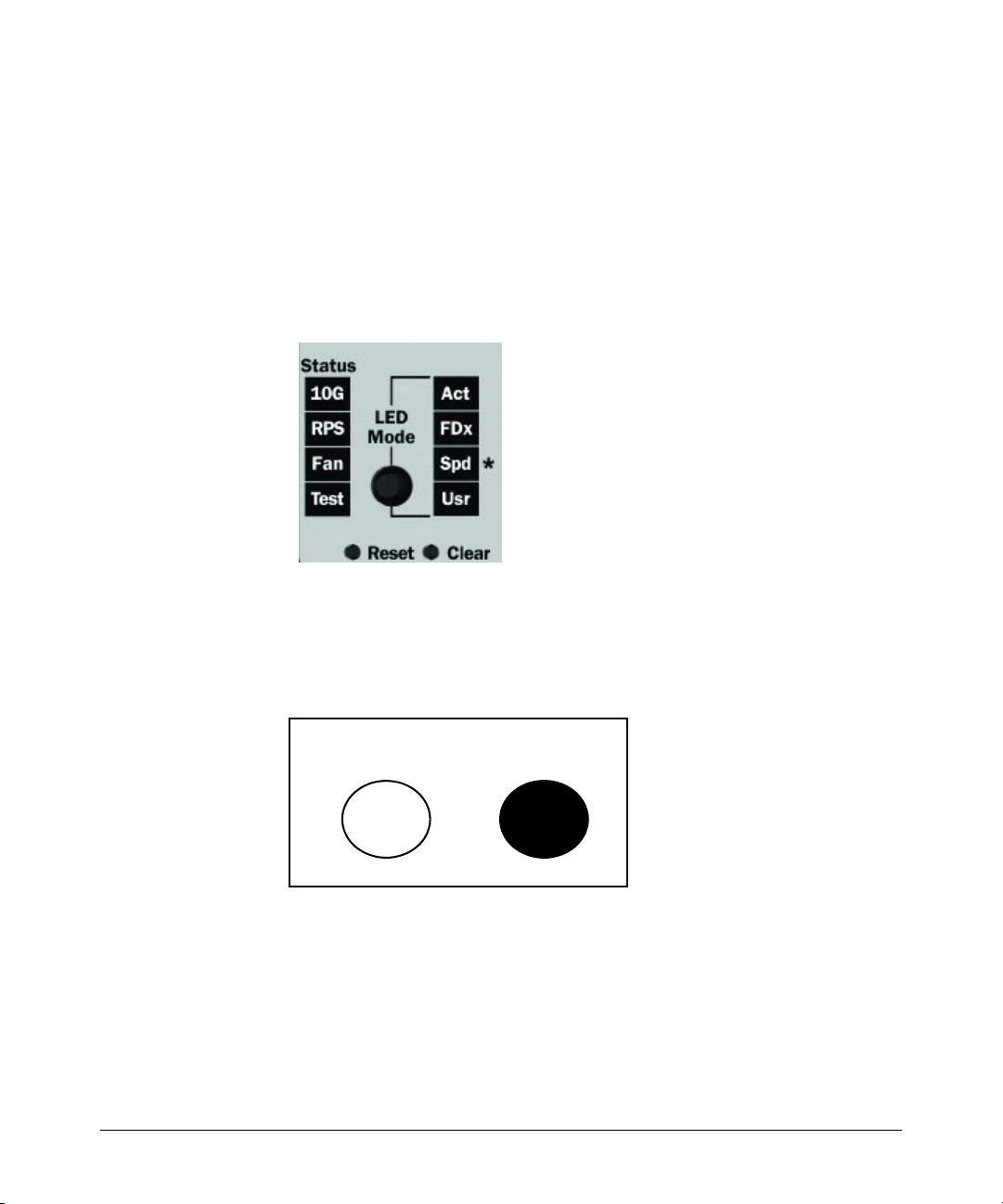
Configuring Username and Password Security
Front-Panel Security
As a result of increased security concerns, customers now have the ability to
stop someone from removing passwords by disabling the Clear and/or Reset
buttons on the front of the switch.
Front-Panel Button Functions
The System Support Module (SSM) of the switch includes the System Reset
button and the Clear button.
Figure 2-6. Front-Panel Reset and Clear Buttons
2-24
Clear Button
Pressing the Clear button alone for one second resets the password(s) configured on the switch.
Reset Clear
Figure 2-7. Press the Clear Button for One Second To Reset the Password(s)
Page 73

Configuring Username and Password Security
Front-Panel Security
Reset Button
Pressing the Reset button alone for one second causes the switch to reboot.
Reset Clear
Figure 2-8. Press and hold the Reset Button for One Second To Reboot the Switch
Restoring the Factory Default Configuration
You can also use the Reset button together with the Clear button (Reset+Clear)
to restore the factory default configuration for the switch. To do this:
1. Press and hold the Reset button.
Reset Clear
2. While holding the Reset button, press and hold the Clear button.
Reset Clear
3. Release the Reset button.
2-25
Page 74

Configuring Username and Password Security
Front-Panel Security
Reset Clear
4. When the Test LED to the right of the Clear button begins flashing, release
the Clear button.
.
Reset Clear
Test
Test
2-26
It can take approximately 20-25 seconds for the switch to reboot. This process
restores the switch configuration to the factory default settings.
Configuring Front-Panel Security
Using the front-panel-security command from the global configuration context
in the CLI you can:
• Disable or re-enable the password-clearing function of the Clear
button. Disabling the Clear button means that pressing it does not
remove local password protection from the switch. (This action
affects the Clear button when used alone, but does not affect the
operation of the Reset+Clear combination described under “Restoring the Factory Default Configuration” on page 2-25.)
• Configure the Clear button to reboot the switch after clearing any
local usernames and passwords. This provides an immediate, visual
means (plus an Event Log message) for verifying that any usernames
and passwords in the switch have been cleared.
Page 75

Configuring Username and Password Security
Front-Panel Security
• Modify the operation of the Reset+Clear combination (page 2-25) so
that the switch still reboots, but does not restore the switch’s factory
default configuration settings. (Use of the Reset button alone, to
simply reboot the switch, is not affected.)
• Disable or re-enable Password Recovery.
Syntax: show front-panel-security
Displays the current front-panel-security settings:
Clear Password: Shows the status of the Clear button on the
front panel of the switch. Enabled means that pressing the
Clear button erases the local usernames and passwords
configured on the switch (and thus removes local password
protection from the switch). Disabled means that pressing the
Clear button does not remove the local usernames and
passwords configured on the switch. (Default: Enabled.)
Reset-on-clear: Shows the status of the reset-on-clear option
(Enabled or Disabled). When reset-on-clear is disabled and
Clear Password is enabled, then pressing the Clear button
erases the local usernames and passwords from the switch.
When reset-on-clear is enabled, pressing the Clear button
erases the local usernames and passwords from the switch
and reboots the switch. (Enabling reset-on-clear
automatically enables clear-password.) (Default: Disabled.)
Note: If you have stored security credentials (including the
local manager and operator usernames and passwords) to the
running config file by entering the include-credentials
command, the Reset-on-clear option is ignored. If you press
the Clear button on the front panel, the manager and operator
usernames and passwords are deleted from the startup
configuration file, but the switch does not reboot. For more
information about storing security credentials, see “Saving
Security Credentials in a Config File” on page 2-10 in this
guide.
Factory Reset: Shows the status of the System Reset button on
the front panel of the switch. Enabled means that pressing the
System Reset button reboots the switch and also enables the
System Reset button to be used with the Clear button (page
2-25) to reset the switch to its factory-default configuration.
(Default: Enabled.)
2-27
Page 76

Configuring Username and Password Security
Front-Panel Security
Password Recovery: Shows whether the switch is configured
with the ability to recover a lost password. (Refer to
“Password Recovery Process” on page 2-34.) (Default:
Enabled.)
For example, show front-panel-security produces the following output when
the switch is configured with the default front-panel security settings.
Figure 2-9. The Default Front-Panel Security Settings
CAUTION: Disabling this option removes the ability to
recover a password on the switch. Disabling this option is
an extreme measure and is not recommended unless you
have the most urgent need for high security. If you disable
password-recovery and then lose the password, you will
have to use the Reset and Clear buttons (page 2-25) to reset
the switch to its factory-default configuration and create a
new password.
2-28
Page 77

Configuring Username and Password Security
Front-Panel Security
Disabling the Clear Password Function of the Clear Button
on the Switch’s Front Panel
Syntax: no front-panel-security password-clear
In the factory-default configuration, pressing the Clear button
on the switch’s front panel erases any local usernames and
passwords configured on the switch. This command disables
the password clear function of the Clear button, so that
pressing it has no effect on any local usernames and
passwords.
(Default: Enabled.)
Note: Although the Clear button does not erase passwords
when disabled, you can still use it with the Reset button
(Reset+Clear) to restore the switch to its factory default
configuration, as described under “Restoring the Factory
Default Configuration” on page 2-25.
This command displays a Caution message in the CLI. If you want to proceed
with disabling the Clear button, type
[Y]; otherwise type [N]. For example:
Indicates the command has disabled the Clear
button on the switch’s front panel. In this case
the Show command does not include the reset-
on-clear status because it is inoperable while
the Clear Password functionality is disabled, and
must be reconfigured whenever Clear Password
is re-enabled .
Figure 2-10. Example of Disabling the Clear Button and Displaying the New Configuration
2-29
Page 78

Configuring Username and Password Security
Front-Panel Security
Re-Enabling the Clear Button on the Switch’s Front Panel
and Setting or Changing the “Reset-On-Clear” Operation
Syntax: [no] front-panel-security password-clear reset-on-clear
This command does both of the following:
• Re-enables the password-clearing function of the Clear
button on the switch’s front panel.
• Specifies whether the switch reboots if the Clear button is
pressed.
To re-enable password-clear, you must also specify whether to
enable or disable the reset-on-clear option.
Defaults:
– password-clear: Enabled.
– reset-on-clear: Disabled.
Thus:
• To enable password-clear with reset-on-clear disabled, use
this syntax:
• To enable password-clear with reset-on-clear also enabled,
use this syntax:
(Either form of the command enables
no front-panel-security password-clear reset-on-clear
front-panel-security password-clear reset-on-clear
password-clear.)
2-30
Note: If you disable password-clear and also disable the
password-recovery option, you can still recover from a lost
password by using the Reset+Clear button combination at
reboot as described on page 2-25. Although the Clear button
does not erase passwords when disabled, you can still use
it with the Reset button (Reset+Clear) to restore the switch
to its factory default configuration. You can then get access
to the switch to set a new password.
For example, suppose that password-clear is disabled and you want to restore
it to its default configuration (enabled, with reset-on-clear disabled).
Page 79

Configuring Username and Password Security
Figure 2-11. Example of Re-Enabling the Clear Button’s Default Operation
Changing the Operation of the Reset+Clear Combination
In their default configuration, using the Reset+Clear buttons in the combination described under “Restoring the Factory Default Configuration” on page
2-25 replaces the switch’s current startup-config file with the factory-default
startup-config file, then reboots the switch, and removes local password
protection. This means that anyone who has physical access to the switch
could use this button combination to replace the switch’s current configuration with the factory-default configuration, and render the switch accessible without the need to input a username or password. You can use the
factory-reset command to prevent the Reset+Clear combination from being
used for this purpose.
Front-Panel Security
Shows password-clear disabled.
Enables password-clear, with reset-on-
clear disabled by the “no” statement at
the beginning of the command.
Shows password-clear enabled, with
reset-on-clear disabled.
Syntax: [no] front-panel-security factory-reset
Disables or re-enables the following functions associated with
using the Reset+Clear buttons in the combination described
under “Restoring the Factory Default Configuration” on page
2-25:
• Replacing the current startup-config file with the factorydefault startup-config file
• Clearing any local usernames and passwords configured on
the switch
(Default: Both functions enabled.)
Notes: The Reset+Clear button combination always reboots
the switch, regardless of whether the “no” form of the
command has been used to disable the above two functions.
Also, if you disable factory-reset, you cannot disable the
password-recovery option, and the reverse.
2-31
Page 80

Configuring Username and Password Security
Front-Panel Security
The command to disable the factory-reset operation produces this caution.
To complete the command, press [Y]. To abort the command, press [N].
Figure 2-12. Example of Disabling the Factory Reset Option
Password Recovery
The password recovery feature is enabled by default and provides a method
for regaining management access to the switch (without resetting the switch
to its factory default configuration) in the event that the system administrator
loses the local manager username (if configured) or password. Using Password Recovery requires:
■ password-recovery enabled (the default) on the switch prior to an attempt
to recover from a lost username/password situation
■ Contacting your ProCurve Customer Care Center to acquire a one-time-
use password
Completes the command to
disable the factory reset option.
Displays the current frontpanel-security configuration,
with Factory Reset disabled.
2-32
Disabling or Re-Enabling the Password Recovery Process
Disabling the password recovery process means that the only method for
recovering from a lost manager username (if configured) and password is to
reset the switch to its factory-default configuration, which removes any nondefault configuration settings.
Page 81

Configuring Username and Password Security
Front-Panel Security
Caution Disabling password-recovery requires that factory-reset be enabled, and locks
out the ability to recover a lost manager username (if configured) and password on the switch. In this event, there is no way to recover from a lost
manager username/password situation without resetting the switch to its
factory-default configuration. This can disrupt network operation and make
it necessary to temporarily disconnect the switch from the network to prevent
unauthorized access and other problems while it is being reconfigured. Also,
with factory-reset enabled, unauthorized users can use the Reset+Clear button
combination to reset the switch to factory-default configuration and gain
management access to the switch.
Syntax: [no] front-panel-security password-recovery
Enables or (using the “no” form of the command) disables the
ability to recover a lost password.
When this feature is enabled, the switch allows management
access through the password recovery process described below.
This provides a method for recovering from a lost manager
username (if configured) and password. When this feature is
disabled, the password recovery process is disabled and the
only way to regain management access to the switch is to use
the Reset+Clear button combination (page 2-25) to restore the
switch to its factory default configuration.
Note: To disable password-recovery:
–You must have physical access to the front panel of the switch.
–The factory-reset parameter must be enabled (the default).
(Default: Enabled.)
Steps for Disabling Password-Recovery.
1. Set the CLI to the global interface context.
2. Use show front-panel-security to determine whether the factory-reset
parameter is enabled. If it is disabled, use the front-panel-security factory-
reset command to enable it.
3. Press and release the Clear button on the front panel of the switch.
4. Within 60-seconds of pressing the Clear button, enter the following command:
no front-panel-security password-recovery
5. Do one of the following after the “CAUTION” message appears:
• If you want to complete the command, press
[Y] (for “Yes”).
2-33
Page 82

Configuring Username and Password Security
Front-Panel Security
• If you want to abort the command, press [N] (for “No”)
Figure 2-13 shows an example of disabling the password-recovery parameter.
Figure 2-13. Example of the Steps for Disabling Password-Recovery
Password Recovery Process
If you have lost the switch’s manager username/password, but password-
recovery is enabled, then you can use the Password Recovery Process to gain
management access to the switch with an alternate password supplied by
ProCurve.
Note If you have disabled password-recovery, which locks out the ability to recover a
manager username/password pair on the switch, then the only way to recover
from a lost manager username/password pair is to use the Reset+Clear button
combination described under “Restoring the Factory Default Configuration”
on page 2-25. This can disrupt network operation and make it necessary to
temporarily disconnect the switch from the network to prevent unauthorized
access and other problems while it is being reconfigured.
To use the password-recovery option to recover a lost password:
1. Note the switch’s base MAC address. It is shown on the label located on
the upper right front corner of the switch.
2. Contact your ProCurve Customer Care Center for further assistance.
Using the switch’s MAC address, the ProCurve Customer Care Center will
generate and provide a “one-time use” alternate password you can use
with the to gain management access to the switch. Once you gain access,
you can configure a new, known password.
2-34
Page 83

Configuring Username and Password Security
Front-Panel Security
Note The alternate password provided by the ProCurve Customer Care Center is
valid only for a single login attempt. You cannot use the same “one-time-use”
password if you lose the password a second time. Because the password
algorithm is randomized based upon your switch's MAC address, the password will change as soon as you use the “one-time-use” password provided
to you by the ProCurve Customer Care Center.
2-35
Page 84

Configuring Username and Password Security
Front-Panel Security
2-36
Page 85

Web and MAC Authentication
Contents
Overview . . . . . . . . . . . . . . . . . . . . . . . . . . . . . . . . . . . . . . . . . . . . . . . . . . . . . 3-2
Web Authentication . . . . . . . . . . . . . . . . . . . . . . . . . . . . . . . . . . . . . . . . . 3-2
MAC Authentication . . . . . . . . . . . . . . . . . . . . . . . . . . . . . . . . . . . . . . . . . 3-3
Concurrent Web and MAC Authentication . . . . . . . . . . . . . . . . . . . . . . 3-3
Authorized and Unauthorized Client VLANs . . . . . . . . . . . . . . . . . . . . . 3-4
RADIUS-Based Authentication . . . . . . . . . . . . . . . . . . . . . . . . . . . . . . . . 3-5
Wireless Clients . . . . . . . . . . . . . . . . . . . . . . . . . . . . . . . . . . . . . . . . . . . . . 3-5
How Web and MAC Authentication Operate . . . . . . . . . . . . . . . . . . . . 3-5
Web-based Authentication . . . . . . . . . . . . . . . . . . . . . . . . . . . . . . . . . . . . 3-6
MAC-based Authentication . . . . . . . . . . . . . . . . . . . . . . . . . . . . . . . . . . . 3-8
3
Terminology . . . . . . . . . . . . . . . . . . . . . . . . . . . . . . . . . . . . . . . . . . . . . . . . . 3-10
Operating Rules and Notes . . . . . . . . . . . . . . . . . . . . . . . . . . . . . . . . . . . . 3-11
Setup Procedure for Web/MAC Authentication . . . . . . . . . . . . . . . . . 3-13
Before You Configure Web/MAC Authentication . . . . . . . . . . . . . . . . 3-13
Configuring the RADIUS Server To Support MAC Authentication . . 3-15
Configuring the Switch To Access a RADIUS Server . . . . . . . . . . . . 3-16
Configuring Web Authentication . . . . . . . . . . . . . . . . . . . . . . . . . . . . . . 3-18
Overview . . . . . . . . . . . . . . . . . . . . . . . . . . . . . . . . . . . . . . . . . . . . . . . . . . 3-18
Configuration Commands for Web Authentication . . . . . . . . . . . . . . 3-19
Show Commands for Web Authentication . . . . . . . . . . . . . . . . . . . . . . 3-26
Configuring MAC Authentication on the Switch . . . . . . . . . . . . . . . . 3-32
Overview . . . . . . . . . . . . . . . . . . . . . . . . . . . . . . . . . . . . . . . . . . . . . . . . . . 3-32
Configuration Commands for MAC Authentication . . . . . . . . . . . . . . 3-33
Show Commands for MAC-Based Authentication . . . . . . . . . . . . . . . 3-36
Client Status . . . . . . . . . . . . . . . . . . . . . . . . . . . . . . . . . . . . . . . . . . . . . . . . . 3-42
3-1
Page 86

Web and MAC Authentication
Overview
Overview
Feature Default Menu CLI Web
Configure Web Authentication n/a — 3-18 —
Configure MAC Authentication n/a — 3-32 —
Display Web Authentication Status and Configuration n/a — 3-26 —
Display MAC Authentication Status and Configuration n/a — 3-36 —
Web and MAC authentication are designed for employment on the “edge” of
a network to provide port-based security measures for protecting private
networks and a switch from unauthorized access. Because neither method
requires clients to run special supplicant software (unlike 802.1X authentication), both Web and MAC authentication are suitable for legacy systems and
temporary access situations where introducing supplicant software is not an
attractive option. Only a web browser (for Web authentication) or a MAC
address (for MAC authentication) is required.
Both Web and MAC authentication methods rely on a RADIUS server to
authenticate network access. This simplifies access security management by
allowing you to control access from a master database in a single server. (You
can use up to three RADIUS servers to provide backups in case access to the
primary server fails.) It also means the same credentials can be used for
authentication, regardless of which switch or switch port is the current access
point into the LAN.
On a port configured for Web or MAC Authentication, the switch operates as
a port-access authenticator using a RADIUS server and the CHAP protocol.
Inbound traffic is processed by the switch alone, until authentication occurs.
Some traffic from the switch to an unauthorized client is supported (for
example, broadcast or unknown destination packets) before authentication
occurs.
Web Authentication
The Web Authentication (Web-Auth) method uses a web page login to authenticate users for access to the network. When a client connects to the switch
and opens a web browser, the switch automatically presents a login page.
3-2
Page 87

Web and MAC Authentication
Overview
Note A proxy server is not supported for use by a browser on a client device that
accesses the network through a port configured for web authentication.
■ In the login page, a client enters a username and password, which the
switch forwards to a RADIUS server for authentication. After authenticating a client, the switch grants access to the secured network. Besides a
web browser, the client needs no special supplicant software.
MAC Authentication
The MAC Authentication (MAC-Auth) method grants access to a secure
network by authenticating devices for access to the network. When a device
connects to the switch, either by direct link or through the network, the switch
forwards the device’s MAC address to the RADIUS server for authentication.
The RADIUS server uses the device MAC address as the username and
password, and grants or denies network access in the same way that it does
for clients capable of interactive logons. (The process does not use either a
client device configuration or a logon session.) MAC authentication is wellsuited for clients that are not capable of providing interactive logons, such as
telephones, printers, and wireless access points. Also, because most RADIUS
servers allow for authentication to depend on the source switch and port
through which the client connects to the network, you can use MAC-Auth to
“lock” a particular device to a specific switch and port.
Note 802.1X port-access, Web authentication, and MAC authentication can be
configured at the same time on the same port. A maximum of eight clients is
supported on the port. (The default is one client.)
Web and/or MAC authentication and MAC lockdown, MAC lockout, and portsecurity are mutually exclusive on a given port. If you configure any of these
authentication methods on a port, you must disable LACP on the port.
Concurrent Web and MAC Authentication
Web authentication and MAC authentication can be configured at the same
time on a port. It is assumed that MAC authentication will use an existing MAC
address. The following conditions apply for concurrent Web and MAC authentication:
■ A specific MAC address cannot be authenticated by both Web and MAC
authentication at the same time.
3-3
Page 88

Web and MAC Authentication
Overview
■ Each new Web/MAC Auth client always initiates a MAC authentication
■ Web and MAC authentications are not allowed on the same port if unau-
■ Hitless reauthentication must be of the same type (MAC) that was used
The remaining Web/MAC functionality, including interactions with 802.1X,
remains the same. Web and MAC authentication can be used for different
clients on the same port.
Normally, MAC authentication finishes much sooner than Web authentication.
However, if Web authentication should complete first, MAC authentication
will cease even though it is possible that MAC authentication could succeed.
There is no guarantee that MAC authentication ends before Web authentication begins for the client.
attempt. This same client can also initiate Web authentication at any time
before the MAC authentication succeeds. If either authentication succeeds then the other authentication (if in progress) is ended. No further
Web/MAC authentication attempts are allowed until the client is deauthenticated.
thenticated VLAN (that is, a guest VLAN) is enabled for MAC authentication. An unauthenticated VLAN can’t be enabled for MAC authentication
if Web and MAC authentication are both enabled on the port.
for the initial authentication. Non-hitless reauthentication can be of any
type.
3-4
Concurrent Web and MAC authentication is backward compatible with all
existing user configurations.
Authorized and Unauthorized Client VLANs
Web-Auth and MAC-Auth provide a port-based solution in which a port
belongs to one, untagged VLAN at a time. The switch supports up to eight
simultaneous client sessions per port. All authenticated client sessions
operate in the same untagged VLAN. (If you want the switch to simultaneously
support multiple client sessions in different VLANs for a network application,
design your system so that clients request network access on different switch
ports.)
In the default configuration, the switch blocks access to all clients that the
RADIUS server does not authenticate. However, you can configure an
individual port to provide limited network services and access to unauthorized
clients by using an “unauthorized” VLAN for each session. The unauthorized
VLAN ID assignment can be the same for all ports, or different, depending on
the services and access you plan to allow for unauthenticated clients.
Page 89

How Web and MAC Authentication Operate
You configure access to an optional, unauthorized VLAN when you configure
Web and MAC authentication on a port.
Web and MAC Authentication
RADIUS-Based Authentication
In Web and MAC authentication, you use a RADIUS server to temporarily
assign a port to a static VLAN to support an authenticated client. When a
RADIUS server authenticates a client, the switch-port membership during the
client’s connection is determined according to the following hierarchy:
1. A RADIUS-assigned VLAN
2. An authorized VLAN specified in the Web- or MAC-Auth configuration for
the subject port.
3. A static, port-based, untagged VLAN to which the port is configured. A
RADIUS-assigned VLAN has priority over switch-port membership in any
VLAN.
Wireless Clients
You can allow wireless clients to move between switch ports under Web/MAC
Authentication control. Clients may move from one Web-authorized port to
another or from one MAC-authorized port to another. This capability allows
wireless clients to move from one access point to another without having to
reauthenticate.
How Web and MAC Authentication
Operate
Before gaining access to the network, a client first presents authentication
credentials to the switch. The switch then verifies the credentials with a
RADIUS authentication server. Successfully authenticated clients receive
access to the network, as defined by the System Administrator. Clients who
fail to authenticate successfully receive no network access or limited network
access as defined by the System Administrator.
3-5
Page 90

Web and MAC Authentication
How Web and MAC Authentication Operate
Web-based Authentication
When a client connects to a Web-Auth enabled port, communication is redirected to the switch. A temporary IP address is assigned by the switch and a
login screen is presented for the client to enter their username and password.
The default User Login screen is shown in Figure 3-1.
Figure 3-1. Example of Default User Login Screen
When a client connects to the switch, it sends a DHCP request to receive an
IP address to connect to the network. To avoid address conflicts in a secure
network, you can specify a temporary IP address pool to be used by DHCP by
configuring the dhcp-addr and dhcp-lease options when you enable web
authentication with the aaa port-access web-based command.
3-6
The Secure Socket Layer (SSLv3/TLSv1) feature provides remote web access
to the network via authenticated transactions and encrypted paths between
the switch and management station clients capable of SSL/TLS. If you have
enabled SSL on the switch, you can specify the ssl-login option when you
configure web authentication so that clients who log in to specified ports are
redirected to a secure login page (https://...) to enter their credentials.
The switch passes the supplied username and password to the RADIUS server
for authentication and displays the following progress message:
Figure 3-2. Progress Message During Authentication
Page 91
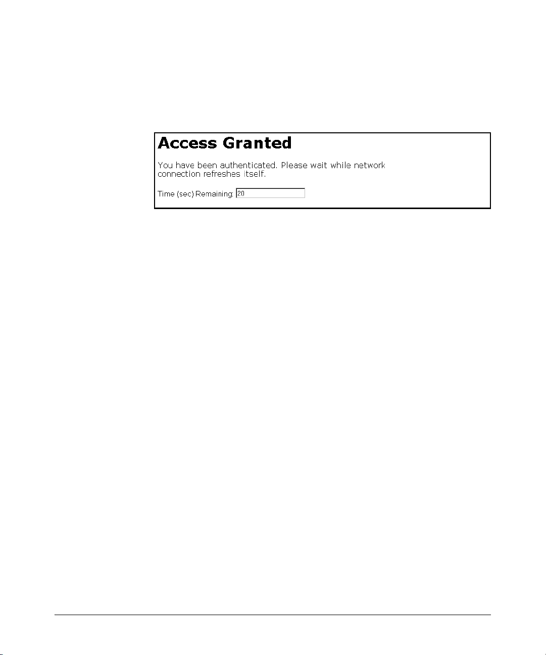
How Web and MAC Authentication Operate
Web and MAC Authentication
If the client is authenticated and the maximum number of clients allowed on
the port (client-limit) has not been reached, the port is assigned to a static,
untagged VLAN for network access. After a successful login, a client may be
redirected to a URL if you specify a URL value (redirect-url) when you
configure web authentication.
Figure 3-3. Authentication Completed
The assigned VLAN is determined, in order of priority, as follows:
1. If there is a RADIUS-assigned VLAN, then, for the duration of the client
session, the port belongs to this VLAN and temporarily drops all other
VLAN memberships.
2. If there is no RADIUS-assigned VLAN, then, for the duration of the client
session, the port belongs to the authorized VLAN (auth-vid if configured)
and temporarily drops all other VLAN memberships.
3. If neither 1 or 2, above, apply, but the port is an untagged member of a
statically configured, port-based VLAN, then the port remains in this
VLAN.
4. If neither 1, 2, or 3, above, apply, then the client session does not have
access to any statically configured, untagged VLANs and client access is
blocked.
The assigned port VLAN remains in place until the session ends. Clients may
be forced to reauthenticate after a fixed period of time (reauth-period) or at
any time during a session (reauthenticate). An implicit logoff period can be set
if there is no activity from the client after a given amount of time (logoff-period).
In addition, a session ends if the link on the port is lost, requiring reauthentication of all clients. Also, if a client moves from one port to another and client
moves have not been enabled (client-moves) on the ports, the session ends and
the client must reauthenticate for network access. At the end of the session
the port returns to its pre-authentication state. Any changes to the port’s VLAN
memberships made while it is an authorized port take affect at the end of the
session.
3-7
Page 92

Web and MAC Authentication
How Web and MAC Authentication Operate
A client may not be authenticated due to invalid credentials or a RADIUS
server timeout. The max-retries parameter specifies how many times a client
may enter their credentials before authentication fails. The server-timeout
parameter sets how long the switch waits to receive a response from the
RADIUS server before timing out. The max-requests parameter specifies how
many authentication attempts may result in a RADIUS server timeout before
authentication fails. The switch waits a specified amount of time (quiet-
period) before processing any new authentication requests from the client.
Network administrators may assign unauthenticated clients to a specific
static, untagged VLAN (unauth-vid), to provide access to specific (guest)
network resources. If no VLAN is assigned to unauthenticated clients the port
is blocked and no network access is available. Should another client successfully authenticate through that port any unauthenticated clients on the unauth-
vid are dropped from the port.
MAC-based Authentication
When a client connects to a MAC-Auth enabled port traffic is blocked. The
switch immediately submits the client’s MAC address (in the format specified
by the addr-format) as its certification credentials to the RADIUS server for
authentication.
3-8
If the client is authenticated and the maximum number of MAC addresses
allowed on the port (addr-limit) has not been reached, the port is assigned to
a static, untagged VLAN for network access.
The assigned VLAN is determined, in order of priority, as follows:
1. If there is a RADIUS-assigned VLAN, then, for the duration of the client
session, the port belongs to this VLAN and temporarily drops all other
VLAN memberships.
2. If there is no RADIUS-assigned VLAN, then, for the duration of the client
session, the port belongs to the Authorized VLAN (auth-vid if configured)
and temporarily drops all other VLAN memberships.
3. If neither 1 or 2, above, apply, but the port is an untagged member of a
statically configured, port-based VLAN, then the port remains in this
VLAN.
4. If neither 1, 2, or 3, above, apply, then the client session does not have
access to any statically configured, untagged VLANs and client access is
blocked.
Page 93

How Web and MAC Authentication Operate
Web and MAC Authentication
The assigned port VLAN remains in place until the session ends. Clients may
be forced to reauthenticate after a fixed period of time (reauth-period) or at
any time during a session (reauthenticate). An implicit logoff period can be set
if there is no activity from the client after a given amount of time (logoff-period).
In addition, a session ends if the link on the port is lost, requiring reauthentication of all clients. Also, if a client moves from one port to another and client
moves have not been enabled (addr-moves) on the ports, the session ends and
the client must reauthenticate for network access. At the end of the session
the port returns to its pre-authentication state. Any changes to the port’s VLAN
memberships made while it is an authenticated port take affect at the end of
the session.
A client may not be authenticated due to invalid credentials or a RADIUS
server timeout. The server-timeout parameter sets how long the switch waits
to receive a response from the RADIUS server before timing out. The max-
requests parameter specifies how many authentication attempts may result in
a RADIUS server timeout before authentication fails. The switch waits a
specified amount of time (quiet-period) before processing any new authentication requests from the client.
Network administrators may assign unauthenticated clients to a specific
static, untagged VLAN (unauth-vid), to provide access to specific (guest)
network resources. If no VLAN is assigned to unauthenticated clients the port
remains in its original VLAN configuration. Should another client successfully
authenticate through that port any unauthenticated clients are dropped from
the port.
3-9
Page 94

Web and MAC Authentication
Terminology
Terminology
Authorized-Client VLAN: Like the Unauthorized-Client VLAN, this is a
Authentication Server: The entity providing an authentication service to
Authenticator: In ProCurve switch applications, a device such as a ProCurve
CHAP: Challenge Handshake Authentication Protocol. Also known as
conventional, static, untagged, port-based VLAN previously configured on
the switch by the System Administrator. The intent in using this VLAN is
to provide authenticated clients with network access and services. When
the client connection terminates, the port drops its membership in this
VLAN.
the switch. In the case of a ProCurve Switch running Web/MAC-Authentication, this is a RADIUS server.
Switch that requires a client or device to provide the proper credentials
(MAC address, or username and password) before being allowed access
to the network.
“CHAP-RADIUS”.
3-10
Client: In this application, an end-node device such as a management station,
workstation, or mobile PC linked to the switch through a point-to-point
LAN link.
Redirect URL: A System Administrator-specified web page presented to an
authorized client following Web Authentication. ProCurve recommends
specifying this URL when configuring Web Authentication on a switch.
Refer to aaa port-access web-based [e] < port-list > [redirect-url < url >] on
page 3-25.
Static VLAN: A VLAN that has been configured as “permanent” on the switch
by using the CLI vlan < vid > command or the Menu interface.
Unauthorized-Client VLAN: A conventional, static, untagged, port-based
VLAN previously configured on the switch by the System Administrator.
It is used to provide limited network access and services to clients who
are not authenticated.
Page 95

Web and MAC Authentication
Operating Rules and Notes
Operating Rules and Notes
■ The switch supports concurrent 802.1X, Web and MAC authentication
operation on a port (with up to 2 clients allowed). However, concurrent
operation of Web and MAC authentication with other types of authentication on the same port is not supported. That is, the following authentication types are mutually exclusive on a given port:
• Web and/or MAC Authentication (with or without 802.1X)
• MAC lockdown
• MAC lockout
• Port-Security
■ Order of Precedence for Port Access Management (highest to lowest):
a. MAC lockout
b. MAC lockdown or Port Security
c. Port-based Access Control (802.1X) or Web Authentication or MAC
Authentication
Port Access When configuring a port for Web or MAC Authentication, be sure that a higher
Management
precedent port access management feature is not enabled on the port. For
example, be sure that Port Security is disabled on a port before configuring
the port for Web or MAC Authentication. If Port Security is enabled on the
port this misconfiguration does not allow Web or MAC Authentication to
occur.
■ VLANs: If your LAN does not use multiple VLANs, then you do not need
to configure VLAN assignments in your RADIUS server or consider using
either Authorized or Unauthorized VLANs. If your LAN does use multiple
VLANs, then some of the following factors may apply to your use of WebAuth and MAC-Auth.
• Web-Auth and MAC-Auth operate only with port-based VLANs. Oper-
ation with protocol VLANs is not supported, and clients do not have
access to protocol VLANs during Web-Auth and MAC-Auth sessions.
• A port can belong to one, untagged VLAN during any client session.
Where multiple authenticated clients may simultaneously use the
same port, they must all be capable of operating on the same VLAN.
• During an authenticated client session, the following hierarchy deter-
mines a port’s VLAN membership:
3-11
Page 96

Web and MAC Authentication
Operating Rules and Notes
■
■
■
■
1. If there is a RADIUS-assigned VLAN, then, for the duration of the
client session, the port belongs to this VLAN and temporarily
drops all other VLAN memberships.
2. If there is no RADIUS-assigned VLAN, then, for the duration of
the client session, the port belongs to the Authorized VLAN (if
configured) and temporarily drops all other VLAN memberships.
3. If neither 1 or 2, above, apply, but the port is an untagged member
of a statically configured, port-based VLAN, then the port remains
in this VLAN.
4. If neither 1, 2, or 3, above, apply, then the client session does not
have access to any statically configured, untagged VLANs and
client access is blocked.
• After an authorized client session begins on a given port, the port’s
VLAN membership does not change. If other clients on the same port
become authenticated with a different VLAN assignment than the first
client, the port blocks access to these other clients until the first client
session ends.
• The optional “authorized” VLAN (auth-vid) and “unauthorized” VLAN
(unauth-vid) you can configure for Web- or MAC-based authentication
must be statically configured VLANs on the switch. Also, if you
configure one or both of these options, any services you want clients
in either category to access must be available on those VLANs.
Where a given port’s configuration includes an unauthorized client VLAN
assignment, the port will allow an unauthenticated client session only
while there are no requests for an authenticated client session on that
port. In this case, if there is a successful request for authentication from
an authorized client, the switch terminates the unauthorized-client session and begins the authorized-client session.
When a port on the switch is configured for Web or MAC Authentication
and is supporting a current session with another device, rebooting the
switch invokes a re-authentication of the connection.
When a port on the switch is configured as a Web- or MAC-based authenticator, it blocks access to a client that does not provide the proper
authentication credentials. If the port configuration includes an optional,
unauthorized VLAN (unauth-vid), the port is temporarily placed in the
unauthorized VLAN if there are no other authorized clients currently using
the port with a different VLAN assignment. If an authorized client is using
the port with a different VLAN or if there is no unauthorized VLAN
configured, the unauthorized client does not receive access to the network.
Web- or MAC-based authentication and LACP cannot both be enabled on
the same port.
3-12
Page 97

Setup Procedure for Web/MAC Authentication
Web and MAC Authentication
Web/MAC Web or MAC authentication and LACP are not supported at the same time on
Authentication
and LACP
a port. The switch automatically disables LACP on ports configured for Web
or MAC authentication.
■ Use the show port-access web-based commands to display session status,
port-access configuration settings, and statistics for Web-Auth sessions.
■ When spanning tree is enabled on a switch that uses 802.1X, Web authen-
tication, or MAC authentication, loops may go undetected. For example,
spanning tree packets that are looped back to an edge port will not be
processed because they have a different broadcast/multicast MAC
address from the client-authenticated MAC address. To ensure that clientauthenticated edge ports get blocked when loops occur, you should
enable loop protection on those ports. For more information, see “Loop
Protection” in the chapter titled “Multiple Instance Spanning-Tree Operation” in the Advanced Traffic Management Guide.
Setup Procedure for Web/MAC
Authentication
Before You Configure Web/MAC Authentication
1. Configure a local username and password on the switch for both the
Operator (login) and Manager (enable) access levels. (While this is not
required for a Web- or MAC-based configuration, ProCurve recommends
that you use a local user name and password pair, at least until your other
security measures are in place, to protect the switch configuration from
unauthorized access.)
2. Determine the switch ports that you want to configure as authenticators.
Note that before you configure Web- or MAC-based authentication on a
port operating in an LACP trunk, you must remove the port from the trunk.
(For more information, refer to the “Web/MAC Authentication and LACP”
on page 3-13.)
To display the current configuration of 802.1X, Web-based, and MAC
authentication on all switch ports, enter the show port-access config
command.
3-13
Page 98

Web and MAC Authentication
Setup Procedure for Web/MAC Authentication
ProCurve(config)# show port-access config
Port Access Status Summary
Port-access authenticator activated [No] : Yes
Allow RADIUS-assigned dynamic (GVRP) VLANs [No] : Yes
Supplicant Authenticator Web Auth Mac Auth
Port Enabled Enabled Enabled Enabled
---- ---------- ------------- -------- -------1 Yes No No Yes
2 No Yes No Yes
3 No Yes No No
4 No No No No
5 No No No No
6 No No No No
7 No No No No
8 No No No No
9 No No No No
10 No No No No
11 No No No No
12 No No No No
...
3-14
Figure 3-4. Example of show port-access config Command Output
3. Determine whether any VLAN assignments are needed for authenticated
clients.
a. If you configure the RADIUS server to assign a VLAN for an authen-
ticated client, this assignment overrides any VLAN assignments configured on the switch while the authenticated client session remains
active. Note that the VLAN must be statically configured on the
switch.
b. If there is no RADIUS-assigned VLAN, the port can join an “Authorized
VLAN” for the duration of the client session, if you choose to configure
one. This must be a port-based, statically configured VLAN on the
switch.
c. If there is neither a RADIUS-assigned VLAN or an “Authorized VLAN”
for an authenticated client session on a port, then the port’s VLAN
membership remains unchanged during authenticated client sessions. In this case, configure the port for the VLAN in which you want
it to operate during client sessions.
Page 99

Setup Procedure for Web/MAC Authentication
Note that when configuring a RADIUS server to assign a VLAN, you can
use either the VLAN’s name or VID. For example, if a VLAN configured in
the switch has a VID of 100 and is named vlan100, you could configure the
RADIUS server to use either “100” or “vlan100” to specify the VLAN.
4. Determine whether to use the optional “Unauthorized VLAN” mode for
clients that the RADIUS server does not authenticate. This VLAN must be
statically configured on the switch. If you do not configure an “Unauthorized VLAN”, the switch simply blocks access to unauthenticated clients
trying to use the port.
5. Determine the authentication policy you want on the RADIUS server and
configure the server. Refer to the documentation provided with your
RADIUS application and include the following in the policy for each client
or client device:
• The CHAP-RADIUS authentication method.
• An encryption key
• One of the following:
– If you are configuring Web-based authentication, include the user
name and password for each authorized client.
– If you are configuring MAC-based authentication, enter the
device MAC address in both the username and password fields of
the RADIUS policy configuration for that device. Also, if you want
to allow a particular device to receive authentication only
through a designated port and switch, include this in your policy.
Web and MAC Authentication
6. Determine the IP address of the RADIUS server(s) you will use to support
Web- or MAC-based authentication. (For information on configuring the
switch to access RADIUS servers, refer to “Configuring the Switch To
Access a RADIUS Server” on page 3-16.)
Configuring the RADIUS Server To Support MAC Authentication
On the RADIUS server, configure the client device authentication in the same
way that you would any other client, except:
■ Configure the client device’s (hexadecimal) MAC address as both user-
name and password. Be careful to configure the switch to use the same
format that the RADIUS server uses. Otherwise, the server will deny
access. The switch provides eight format options:
aabbccddeeff (the default format)
aabbcc-ddeeff
3-15
Page 100

Web and MAC Authentication
Configuring the Switch To Access a RADIUS Server
aa-bb-cc-dd-ee-ff
aa:bb:cc:dd:ee:ff
AABBCCDDEEFF
AABBCC-DDEEFF
AA-BB-CC-DD-EE-FF
AA:BB:CC:DD:EE:FF
■ If the device is a switch or other VLAN-capable device, use the base MAC
address assigned to the device, and not the MAC address assigned to the
VLAN through which the device communicates with the authenticator
switch. Note that the switch applies a single MAC address to all VLANs
configured in the switch. Thus, for a given switch, the MAC address is the
same for all VLANs configured on the switch. (Refer to the chapter titled
“Static Virtual LANs (VLANs)” in the Advanced Traffic Management
Guide for your switch.)
Configuring the Switch To Access a
RADIUS Server
RADIUS Server Configuration Commands
radius-server
ip-address>] below
[host <
[key < global-key-string
radius-server host <
This section describes the minimal commands for configuring a RADIUS
server to support Web-Auth and MAC Auth. For information on other RADIUS
command options, refer to chapter 5, “RADIUS Authentication and Accounting” .
>] below
ip-address> key <server-specific key-string> 3-17
3-16
 Loading...