

HP procurve switch xl modules Installation Manual
installation guide
hp procurve switch
xl modules
www.hp.com/go/hpprocurve


HP ProCurve Switch xl Modules
Installation Guide

© Copyright 2001, 2005 Hewlett-Packard Development Company, L.P. The information contained herein is subject to
change without notice.
This document contains proprietary information, which is protected by copyright. No part of this document may be photocopied,
reproduced, or translated into another language without the prior
written consent of Hewlett-Packard.
Publication Number
5991-2130
March 2005
Applicable Products
HP ProCurve Switch 10/100-TX xl Module (J4820A)
HP ProCurve Switch 100/1000-T xl Module (J4821A)
HP ProCurve Switch 100-FX MTRJ xl Module (J4852A)
HP ProCurve Switch mini-GBIC xl Module (J4878A)
HP ProCurve switch xl PoE Module (J8161A)
HP ProCurve Switch 10/100/1000-T xl Module (J4907A)
HP ProCurve 600 Redundant and External Power
Supply (J8168A)
HP ProCurve 610 External Power Supply (J8169A)
HP ProCurve Switch Access Controller xl Module (J8162A)
Disclaimer
HEWLETT-PACKARD COMPANY MAKES NO WARRANTY
OF ANY KIND WITH REGARD TO THIS MATERIAL,
INCLUDING, BUT NOT LIMITED TO, THE IMPLIED
WARRANTIES OF MERCHANTABILITY AND FITNESS
FOR A PARTICULAR PURPOSE. Hewlett-Packard shall not be
liable for errors contained herein or for incidental or consequential
damages in connection with the furnishing, performance, or use
of this material.
The only warranties for HP products and services are set forth in
the express warranty statements accompanying such products and
services. Nothing herein should be construed as constituting an
additional warranty. HP shall not be liable for technical or editorial
errors or omissions contained herein.
Hewlett-Packard assumes no responsibility for the use or
reliability of its software on equipment that is not furnished by
Hewlett-Packard.
War r anty
See the Customer Support/Warranty booklet included with the
product.
A copy of the specific warranty terms applicable to your HewlettPackard product and replacement parts can be obtained from your
HP sales and service office or HP-authorized reseller.
Hewlett-Packard Company
8000 Foothills Boulevard, m/s 5552
Roseville, California 95747-5552
http://www.hp.com/go/procurve

Contents
Descriptions . . . . . . . . . . . . . . . . . . . . . . . . . . . . . . . . . . . . . . . . . . . . . . . . . . . . . 1
Features . . . . . . . . . . . . . . . . . . . . . . . . . . . . . . . . . . . . . . . . . . . . . . . . . . . . . . . . 3
Features and functionality of the ProCurve Switch Access
Controller xl Module (J8162A). . . . . . . . . . . . . . . . . . . . . . . . . . . . . . . . . . . 4
The ProCurve Switch xl Modules have the following features: . . . . . . . . . . 6
Installing the Modules . . . . . . . . . . . . . . . . . . . . . . . . . . . . . . . . . . . . . . . . . . . . 7
Overview . . . . . . . . . . . . . . . . . . . . . . . . . . . . . . . . . . . . . . . . . . . . . . . . . . . . 7
Installing the Module in an Unused Slot . . . . . . . . . . . . . . . . . . . . . . . . . . . . 8
Installation Precautions: . . . . . . . . . . . . . . . . . . . . . . . . . . . . . . . . . . . . . 8
Installation Procedures: . . . . . . . . . . . . . . . . . . . . . . . . . . . . . . . . . . . . . 8
Installing or Removing the mini-GBICs . . . . . . . . . . . . . . . . . . . . . . . . . . . 10
Connecting an HP ProCurve External Power Supply . . . . . . . . . . . . . . . . . 11
Connecting the EPS connector . . . . . . . . . . . . . . . . . . . . . . . . . . . . . . . 11
Connecting or disconnecting RJ-45 connectors . . . . . . . . . . . . . . . . . . 12
HP ProCurve Switch PoE xl Module Configurations . . . . . . . . . . . . . 13
PoE Power Requirements . . . . . . . . . . . . . . . . . . . . . . . . . . . . . . . . . . . . . . 14
PoE Module LEDs . . . . . . . . . . . . . . . . . . . . . . . . . . . . . . . . . . . . . . . . . . . . 14
Port LEDs . . . . . . . . . . . . . . . . . . . . . . . . . . . . . . . . . . . . . . . . . . . . . . . 14
Status LEDs . . . . . . . . . . . . . . . . . . . . . . . . . . . . . . . . . . . . . . . . . . . . . 15
LED Mode LEDs . . . . . . . . . . . . . . . . . . . . . . . . . . . . . . . . . . . . . . . . . 15
Verifying the Module is Installed Correctly . . . . . . . . . . . . . . . . . . . . . . . . 16
Connecting the Network Cables . . . . . . . . . . . . . . . . . . . . . . . . . . . . . . . . . 17
Verifying the Network Connections Are Working . . . . . . . . . . . . . . . . . . . 20
Customizing the Port Configuration . . . . . . . . . . . . . . . . . . . . . . . . . . . . . . 21
Replacing or Removing a Module . . . . . . . . . . . . . . . . . . . . . . . . . . . . . . . . . . 23
Resetting the Switch . . . . . . . . . . . . . . . . . . . . . . . . . . . . . . . . . . . . . . . . . . . . . 24
Reasons for Resetting the Switch . . . . . . . . . . . . . . . . . . . . . . . . . . . . . . . . 24
Methods of Resetting the Switch . . . . . . . . . . . . . . . . . . . . . . . . . . . . . . . . . 24
Troubleshooting . . . . . . . . . . . . . . . . . . . . . . . . . . . . . . . . . . . . . . . . . . . . . . . . 25
PoE LED Behavior . . . . . . . . . . . . . . . . . . . . . . . . . . . . . . . . . . . . . . . . . . . 25
Diagnostic Tips: . . . . . . . . . . . . . . . . . . . . . . . . . . . . . . . . . . . . . . . . . . . . . 26
LED Error Indicators: . . . . . . . . . . . . . . . . . . . . . . . . . . . . . . . . . . . . . 26
iii

Customer Support Services . . . . . . . . . . . . . . . . . . . . . . . . . . . . . . . . . . . . . . . 30
Specifications . . . . . . . . . . . . . . . . . . . . . . . . . . . . . . . . . . . . . . . . . . . . . . . . . . . 30
Environmental . . . . . . . . . . . . . . . . . . . . . . . . . . . . . . . . . . . . . . . . . . . . . . 30
Lasers . . . . . . . . . . . . . . . . . . . . . . . . . . . . . . . . . . . . . . . . . . . . . . . . . . . . . . 30
Connectors . . . . . . . . . . . . . . . . . . . . . . . . . . . . . . . . . . . . . . . . . . . . . . . . . . 31
Twisted-Pair . . . . . . . . . . . . . . . . . . . . . . . . . . . . . . . . . . . . . . . . . . . . . 31
Fiber-Optic . . . . . . . . . . . . . . . . . . . . . . . . . . . . . . . . . . . . . . . . . . . . . . 31
Cables . . . . . . . . . . . . . . . . . . . . . . . . . . . . . . . . . . . . . . . . . . . . . . . . . . . . . 32
Twisted-Pair Cables . . . . . . . . . . . . . . . . . . . . . . . . . . . . . . . . . . . . . . . 32
Fiber-Optic Cables . . . . . . . . . . . . . . . . . . . . . . . . . . . . . . . . . . . . . . . . 33
Mode Conditioning Patch Cord for Gigabit-LX . . . . . . . . . . . . . . . . . . . . . . 34
Installing the Patch Cord . . . . . . . . . . . . . . . . . . . . . . . . . . . . . . . . . . . . . . . 35
Recommended Patch Cords . . . . . . . . . . . . . . . . . . . . . . . . . . . . . . . . . . . . . 35
EMC Regulatory Statements . . . . . . . . . . . . . . . . . . . . . . . . . . . . . . . . . . . . . . 36
U.S.A. . . . . . . . . . . . . . . . . . . . . . . . . . . . . . . . . . . . . . . . . . . . . . . . . . . . . . 36
Canada . . . . . . . . . . . . . . . . . . . . . . . . . . . . . . . . . . . . . . . . . . . . . . . . . . . . . 36
Australia/New Zealand . . . . . . . . . . . . . . . . . . . . . . . . . . . . . . . . . . . . . . . . 36
Japan . . . . . . . . . . . . . . . . . . . . . . . . . . . . . . . . . . . . . . . . . . . . . . . . . . . . . . 36
Korea . . . . . . . . . . . . . . . . . . . . . . . . . . . . . . . . . . . . . . . . . . . . . . . . . . . . . . 37
Taiwan . . . . . . . . . . . . . . . . . . . . . . . . . . . . . . . . . . . . . . . . . . . . . . . . . . . . . 37
European Community Declaration of Conformity . . . . . . . . . . . . . . . . . . . 37
iv
HP ProCurve Switch xl Modules
Descriptions
HP ProCurve Switch xl Modules
For the HP ProCurve Series 5300xl Switches
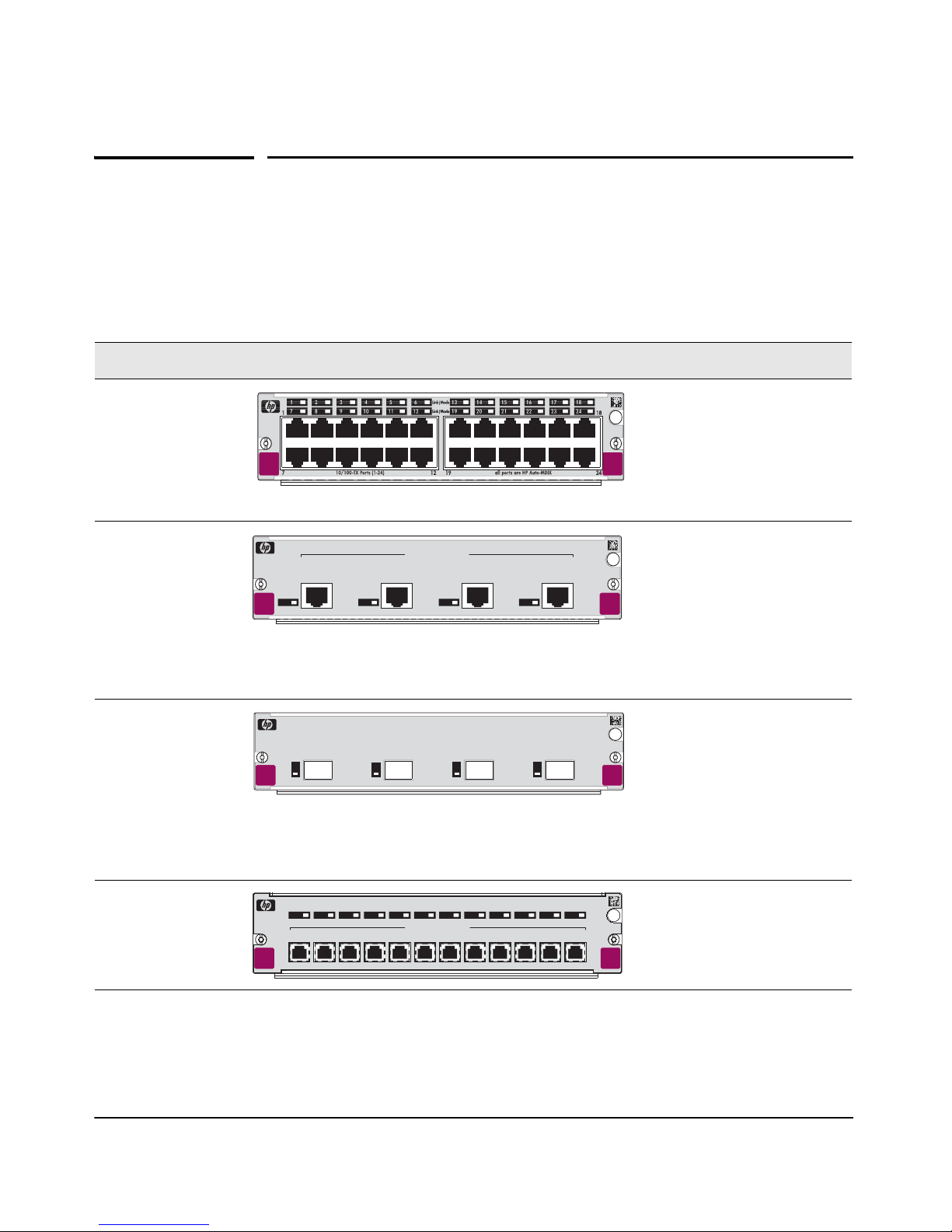
Descriptions. The HP ProCurve Switch xl Modules are components that you
can add to an HP ProCurve xl switch to provide a variety of network connectivity options. The following modules are available as of this printing:
Module Description
HP ProCurve Switch
10/100-TX xl Module
(J4820A)
hp procurve
10
/
100-TX
xl module
J4820B
24 twisted-pair ports with RJ-45
connectors for 10 Mbps or 100
Mbps operation over 100-ohm
unshielded (UTP) or shielded
xl
(STP) twisted-pair cable -- all
module
ports have the HP Auto-MDIX
feature.
HP ProCurve Switch
100/1000-T xl
Module (J4821A)
hp procurve
100/1000-T
xl module
J4821B
Link|Mode
1
100/1000Base-T Ports
4321
432
4 twisted-pair ports with RJ-45
connectors for 1000 Mbps
(Gigabit) or 100 Mbps
operation over Category 5 or
xl
module
better 100-ohm UTP or STP
cable (category 5e
recommended for Gigabit) -- all
ports have the IEEE 802.3ab
Auto MDI/MDI-X feature.
HP ProCurve Switch
mini-GBIC xl
Module (J4878A)
hp procurve
mini-GBIC
xl module
J4878B
Link
Link
1
1
Mode
Mode
2
3
4321
4
4 slots for installing any of the
supported HP ProCurve miniGBICs*.
xl
module
* Supported mini-GBICs: The following HP ProCurve mini-GBICs are supported by the mini-GBIC xl Module
(as of this printing): • Gigabit-SX LC mini-GBIC (J4858A) • Gigabit-LX LC mini-GBIC (J4859A) • Gigabit-LH
LC mini-GBIC (J4860A) • Gigabit 1000Base-T mini-GBIC (J8177B)
HP ProCurve Switch
100-FX MTRJ
xl Module (J4852A)
1
Link|Mode
2
123456789101112
hp procurve
100-FX MTRJ
xl module
J4852A
31 4 5 6 7 8 9 10
100Base-FX MTRJ Ports
12 100-FX ports with MT-RJ
12
11
connectors for 100 Mbps
networking over multimode
fiber-optic cable.
xl
module
1
HP ProCurve Switch xl Modules
Descriptions
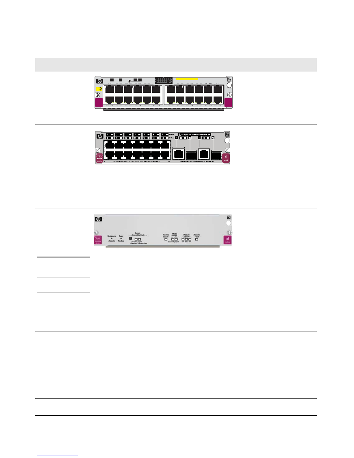
Module Description
HP ProCurve Switch
PoE xl Module
(J8161A) 2
PoE
hp procurve
xl module
J8161A
Link
1
PoE
7
LED Mode
Status
EPS
PoE
Mode
Std PoE
2
3
8
9
5
6
4
10
12
11
PoE-Ready 10/100-TX Ports (1-24) all ports are HP Auto-MDIX
13 14
20
19
16
15
2221
Link
17 18
23
Mode
module
24
HP ProCurve Switch
10/100/1000-T xl
Module (J4907A)
3
The following HP ProCurve mini-GBICs are supported by the 10/100/1000-T
xl Module (as of this printing): • Gigabit-SX LC mini-GBIC (J4858A) • GigabitLX LC mini-GBIC (J4859A) • Gigabit-LH LC mini-GBIC (J4860A)
• The Gigabit 1000Base-T mini-GBIC (J8177B) is not supported on the
10/100/1000-T xl Module (J4907A).
HP ProCurve Switch
Access Controller xl
Module (J8162A)
Note
4
Due to power consumption, no more than two
J8162As are supported in the chassis at a time.
24 10/100-TX ports and when
connected to an HP ProCurve
600 Redundant and External
Power Supply (J8168A), can
xl
provide Power over Ethernet
(PoE) power to 802.3af
compliant devices.
14 twisted-pair ports with RJ-45
connectors for 10/100/1000
Mbps (Gigabit) or 100 Mbps
operation over Category 5 or
better 100-ohm UTP or STP
cable (category 5e
recommended for Gigabit) -- all
ports have the IEEE 802.3ab
Auto MDI/MDI-X feature, and 2
slots for installing any supported ProCurve mini-
GBICs.
There are no ports on the
J8162A. It operates as a
wireless access controller.
Wireless traffic is directed to
this module using VLAN’s. For
configuration information see
your HP ProCurve Series
5300xl Switches Installation
and Getting Started Guide,
Chapter 3, “Getting Started
with Switch Configuration”.
WARNING
This product contains a Lithium coin-type battery (type CR2032) that requires
special handling at end-of-life. The battery can explode or cause burns if
disassembled, charged, or exposed to water, fire or high temperature. After
replacing the battery, properly dispose of used battery.
1
This module requires switch software version E.07.01 or later to be installed in the switch.
2
This module requires switch software version E.08.20 or later to be installed in the switch.
3
This module requires switch software version E.08.42 or later to be installed in the switch.
4
This module requires switch software version E.09.2x or later to be installed in the switch.
Contact your HP-authorized networking products reseller or your HP representative for information
on availability of other modules and mini-GBICs. You can also visit the HP networking products
web site http://www.hp.com/go/procurve to get more information.
2
Features
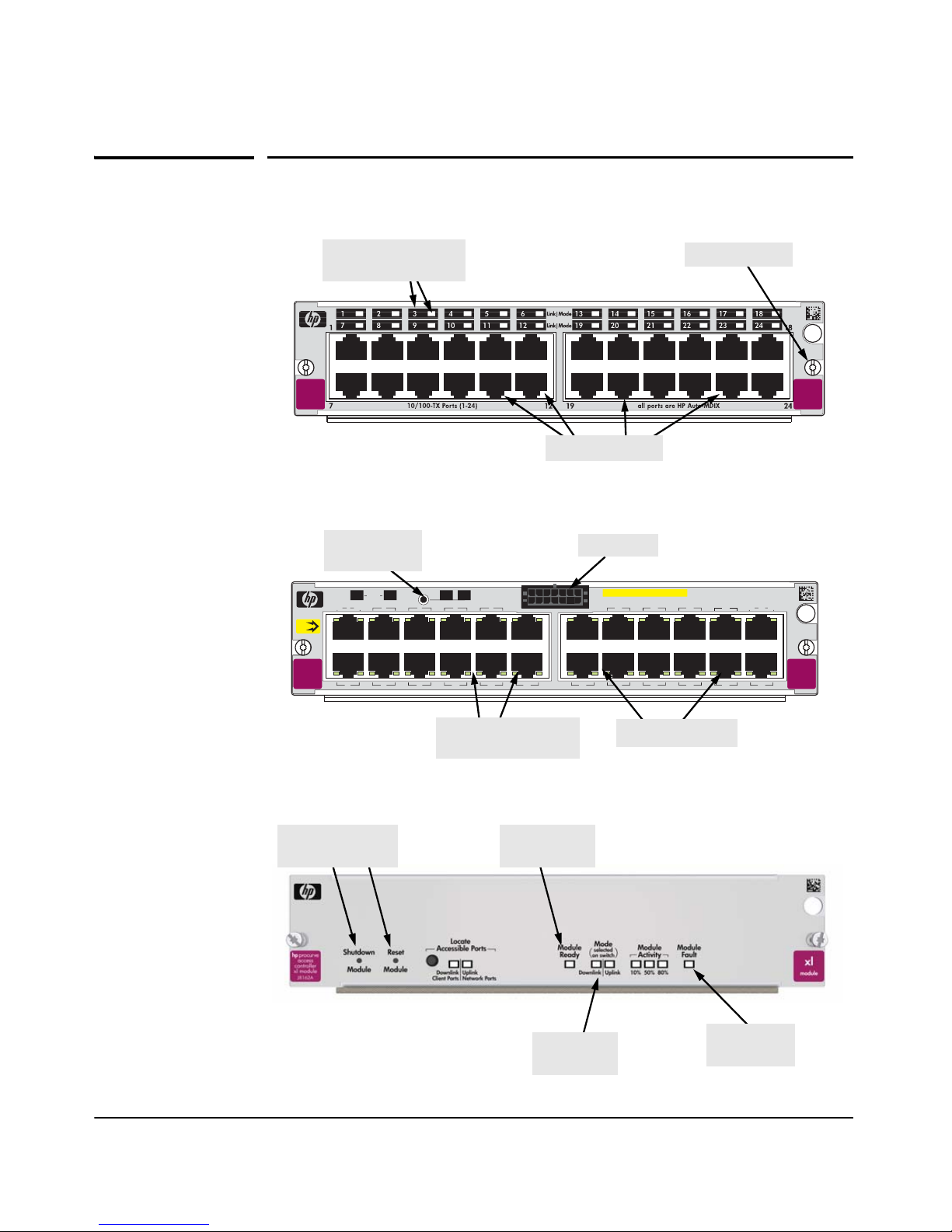
HP ProCurve Switch xl Modules
Features
Link and Mode LEDs
(one pair per port)
hp procurve
/
100-T X
10
xl module
J4820A
Example: HP ProCurve 24-Port 10/100-TX xl Module
LED Mode
Select Button
Status
PoE
Mode
Link
1
PoE
hp procurve
PoE
xl module
J8161A
7
retaining screw
xl
module
network ports
EPS Input
LED Mode
EPS
2
8
Std PoE
3
9
5
4
10
6
12
11
PoE-Ready 10/100-TX Ports (1-24) all ports are HP Auto-MDIX
13 14
20
19
16
15
2221
Link
17 18
23
Mode
xl
module
24
Link and Mode LEDs
Network ports
(one pair per port)
Example: HP ProCurve Switch PoE xl Mod-
Shutdown and
Reset buttons
Module
Ready LED
Link and
Mode LEDs
Module
Fault LED
Example: HP ProCurve Switch Access Controller xl Module
3

HP ProCurve Switch xl Modules
Features
Features and functionality of the ProCurve Switch
Access Controller xl Module (J8162A).
■ Shutdown Module—This is a recessed push button switch that when
pressed and held for more than 2 seconds, initiates an orderly shutdown.
During the shutdown process the Module Ready LED blinks. When the
shutdown is complete enough for a safe module removal, the Module
Ready LED turns off. It is highly recommended to shutdown the module
before resetting or removing the module.
■ Reset Module—This is a recessed push button switch. When this switch
is pressed it causes an immediate reset of the module’s hardware. Pressing
this switch after the shutdown completes will initiate an orderly restart
of the module. It is highly recommended to not press this switch before a
shutdown completes. This could cause unpredictable activity by the
module.
■ Locate Accessible Ports—This button is used to display the associated
downlink and uplink ports. The first press of the button lights the Downlink Client Ports LED on the module and also lights all associated Downlink Client Port LEDs on the other modules in the switch chassis.
Downlink ports connect to devices such as wireless access points. If the
button is not pressed again within a few seconds the LEDs turn off and
the button is reset to the first position. Upon initial installation there are
no Downlink Client Ports. For more information, see the Management
and Configuration Guide on the Documentation CD-ROM that came with
your switch or for the latest version you can also visit the HP networking
products web site http://www.hp.com/go/procurve.
The second press of the button lights the Uplink Network Ports LED on
the module and also lights all associated Uplink Port LEDs on the other
associated modules in the switch chassis. Uplink ports are those typically
used for connecting to the fabric. The ProCurve Switch Access Controller
xl Module will communicate with the ProCurve Access Control Server
740wl (J8154A) or the ProCurve Integrated Access Manager 760wl
(J8155A) through one of these ports.
If the button is not pressed again within a few seconds the LEDs will turn
off and the button is reset to the first position.
A third press of the button turns all accessible port LEDs off and resets
the button to the first position.
• Downlink Client Ports—This LED is associated with the Locate
Accessible Ports button and comes on when the button is pressed
once.
• Uplink Network Ports—This LED is associated with the Locate
Accessible Ports button and comes on when the button is pressed for
the second time.
4
HP ProCurve Switch xl Modules
Features
■ Module Ready LED—This LED comes on after the module completes the
boot up and self test processes and indicates the module is up and running.
■ Mode (selected on switch)—These LEDs operate in conjunction with the
Mode Select button on the switch chassis to show port activity, duplex
mode and link speed. For example, if you have selected “Act” with the
Mode Select button on the chassis, then the two Mode LEDs on the module
(Downlink and Uplink) will blink if there is activity on those ports. For
more information refer to LEDs on Page 1-6 of the HP ProCurve Series
5300xl Switches Installation and Getting Started Guide.
■ Module Activity (10%, 50%, 80%)—These LEDs come on according to the
amount of activity or load the module is experiencing. For example, 10%
indicates that the module has a light load, however, 80% indicates that the
module is nearing work load saturation.
■ Module Fault—This LED (colored orange) comes on when there is an
error condition detected in the module.
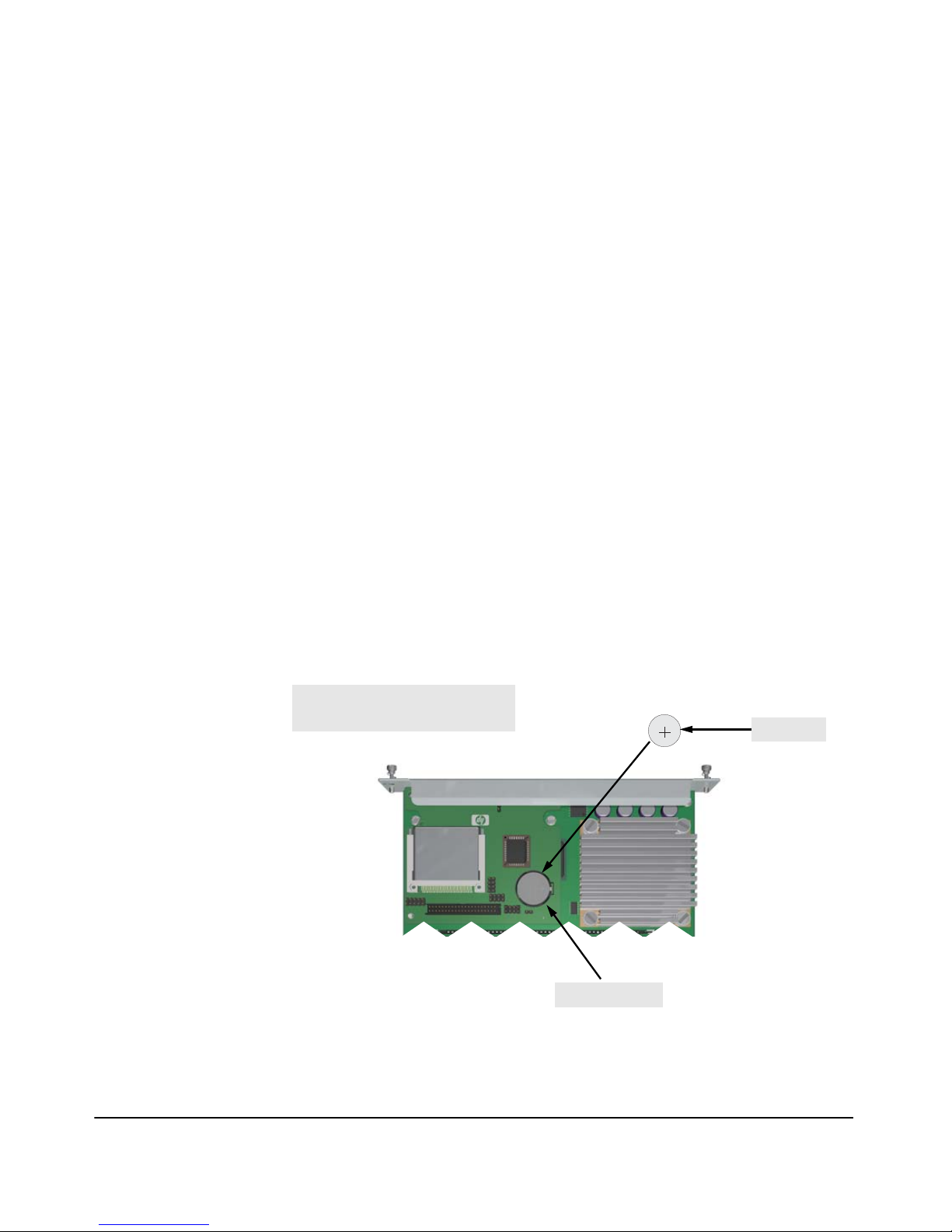
Battery Installation Required
The Access Controller xl Module (J8162A) ships without the clock battery
installed. You must insert the battery before installing the module into the
switch. See the following graphic for instructions.
Insert the battery with the lettering
and the plus “+” sign facing up.
Battery Slot
0
3
2
R
2
C
3
L
L
V
E
O
C
L
T
M
L
I
U
I
T
H
Battery
5

HP ProCurve Switch xl Modules
Features
The ProCurve Switch xl Modules have the following
features:
■ auto-enabled ports—the ports are all configured to be ready for network
operation as soon as a viable network cable is connected
■ auto-configuration—a default configuration is applied to the module
when the switch is powered on and the module passes self test; this default
configuration works well for most network installations
■ LEDs that provide information for each port on the link status, network
activity, connection bandwidth (speed), communication mode (half or full
duplex), and presence of specific network error packets on the port
■ “hot swap modules” operation—you can add a module or replace a
module without having to shut down the switch (changing the module
type in a given slot does require a switch reset)
■ “hot swap mini-GBICs” operation—you can add, replace, or change the
type of any of the mini-GBICs that you use in the mini-GBIC xl Module,
without having to first remove the module, and without having to shut
down the switch
■ the ports on the 10/100-TX and PoE Modules have the HP Auto-MDIX
feature, and the ports on the 100/1000-T xl Module have the IEEE 802.3ab
Auto MDI/MDI-X feature. These features operate the same way and
allow you to use either straight-through or crossover twisted-pair cables
for all the twisted-pair network connections. Please see the note on
“Automatic Cable Sensing” on page 20.
■ the ports on the PoE xl Module have the same functionality as the 10/100-
TX xl Module and also include PoE functionality when connected to an
HP ProCurve 600 Redundant and External Power Supply (J8168A).
■ standards adherence:
• the 10/100-TX xl Module is compatible with the IEEE 802.3
10Base-T and IEEE 802.3u 100Base-TX standards
• the 100/1000-T xl Module is compatible with the IEEE 802.3ab
1000Base-T and IEEE 802.3u 100Base-TX standards
• the ports on the SX and LX mini-GBICs that are installed in the
mini-GBIC xl Module are compatible with the IEEE 802.3z
Gigabit-SX and Gigabit-LX standards respectively.
• the ports on the 100-FX MTRJ xl Module are compatible with the IEEE
802.3u 100-FX standard.
• the PoE xl Module is compatible with the IEEE 802.3 10Base-T, 802.3u
100Base-TX, and the 802.3af Power over Ethernet standards.
• the 16 port 10/100/1000Base-T xl Module is compatible with 802.3
(10Base-T), 802.3u (100Base-TX), and 802.3ab (1000Base-T) IEEE
standards.
6

HP ProCurve Switch xl Modules
Installing the Modules
Installing the Modules
Overview
Before installing any module, ensure you have loaded the most current
software for that module onto your switch, see page 2 for module software
codes. You can install any of the modules into any of the HP ProCurve xl
Switches that have a compatible module slot. As of this printing, those are the
HP ProCurve Series 5300xl Switches:
■ 5308xl (p/n J4819A)
■ 5372xl (p/n J4848B)
■ 5348xl (p/n J4849B)
■ 5304xl (p/n J4850A)
“Hot Swap”
Notes
The mini-GBICs can be “hot swapped”. That is, they can be installed or
removed after the mini-GBIC xl Module is installed in the switch and the
module is receiving power, see page 10.
You can “hot-swap” one module for another; that is, replace one module with
another while the switch is still powered on, without interrupting the operation of the rest of the switch ports, see page 24. You may have to reconfigure
the switch if the modules are not the same type, check your configuration.
You can install the modules into the switch either with the switch powered on
or off. The following procedures assume the switch is powered on.
1. Install the modules in a switch slot (page 8).
If you have installed any modules into slots that were previously occupied
by a different type module, you need to reset the switch (page 25).
2. If you are using the mini-GBIC xl Module, install the mini-GBICs in the
module. You can install the mini-GBICs before or after installing that
module into the switch (page 10).
3. Optionally, connect an HP ProCurve 600 Redundant and External Power
Supply to the xl PoE EPS input, using the supplied EPS cable (page 11).
4. Verify the modules are installed correctly (page 17).
5. Connect the network cabling (page 18).
6. Verify the network connections are working properly (page 21).
7. Optionally, customize the configuration for the modules’ ports (unless
the default port configuration is satisfactory for your network application
(page 22)).
7

HP ProCurve Switch xl Modules
Installing the Modules
Installing the Module in an Unused Slot
Installation Precautions:
■ Static electricity can severely damage the electronic components on the modules. When
handling and installing the modules in your switch, follow these procedures to avoid damage
from static electricity:
• Handle the module by its bulkhead or edges and avoid touching the components and the
circuitry on the board.
• When installing the module, equalize any static charge difference between your body and
the switch by wearing a grounding wrist strap and attaching it to the switch’s metal body,
or by frequently touching the switch’s metal body.
■ The HP ProCurve Switch xl Modules have “low-force”, high-performance connectors.
High insertion forces are not necessary to install the modules, and should not be
used.
■ Ensure you fully insert the modules. That is, press the module into the slot until the
bulkhead on the module is contacting or is very close to contacting the front face of the switch
chassis.
■ Once the module is fully inserted, make sure you screw in the two retaining screws to secure
the module in place.
■ For safe operation, proper switch cooling, and reduction of electromagnetic emissions, ensure
that a slot cover is installed on any unused module slot. For safety, no more than one slot should
be uncovered at a time when the switch is powered on.
Installation Procedures:
1. Use a Torx T-10 or flat-bladed screwdriver to unscrew the screws in the
cover plate over the slot you want to use, and remove the cover. Store
the cover plate for possible future use.
2. Hold the module by its bulkhead—taking care not to touch the metal
connectors or components on the board.
3. As shown in the following illustrations, insert the module into the slot
guides and slide it into the slot until it stops. Then press near the two
screws on the module bulkhead to seat the module connector into the
switch backplane. The module bulkhead should be in contact with or
very close to contact with the back face of the switch.
8
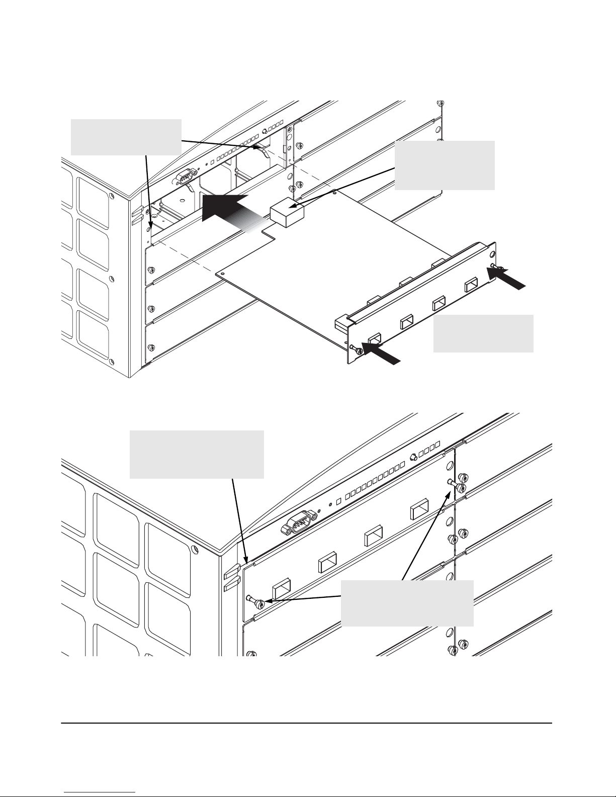
1. Insert module into the
guides and slide it in until
it is fully inserted.
HP ProCurve Switch xl Modules
Installing the Modules
“Low-force”
connector.
High insertion force is
not needed and should
For best results, push
simultaneously near
both screws.
The module is fully inserted
when the module bulkhead is
contacting, or very close to
contacting
2. Then tighten the retaining
screws on the module until they
are secure, but do not
overtighten them.
9
 Loading...