

HP ProCurve Switch 5406zl, ProCurve Switch 5406zl-48G, ProCurve Switch 5412zl, ProCurve Switch 5412zl-96G, ProCurve Switch 8212zl Installation And Getting Started Manual
Installation and Getting
Started Guide
www.hp.com/networking
ProCurve Switch
ONE Services zl Module
zlSM .book Page i T hursday, January 29, 2009 11:53 AM
HP ProCurve Services zl Module
Installation and Getting Started Guide
zlSM .book Page ii Thursda y , January 29, 2009 11:53 AM
© Copyright 2008, 2009, 2012 Hewle
Company, L.P.
tt-Packard Development
Publication Number
5998-3250
March 2012
Applicable Products
P P
H
roCurve Switch 5406zl J8697A
HP ProCurve Switch 5406zl-48G J8699A
HP ProCurve Switch 5412zl J8698A
HP ProCurve Switch 5412zl-96G J8700A
HP ProCurve Switch 8212zl J8715A
Software Credits and Notices
SSL on HP ProCurve Switches is based on the OpenSSL
software toolkit. This product includes software developed
by the OpenSSL Project for use in the OpenSSL Toolkit. For
more information on OpenSSL, visit www.openssl.org.
Disclaimer
HEWLETT-PACKARD COMPANY MAKES NO WARRANTY
OF ANY KIND WITH REGARD TO THIS MATERIAL,
INCLUDING, BUT NOT LIMITED TO, THE IMPLIED
WARRANTIES OF MERCHANTABILITY AND FITNESS
FOR A PARTICULAR PURPOSE. Hewlett-Packard shall not
be liable for errors contained herein or for incidental or
consequential damages in connection with the furnishing,
performance, or use of this material.
The information contained herein is subject to change
without notice. The only warranties for HP products and
services are set forth in the express warranty statements
accompanying such products and services. Nothing herein
should be construed as constituting an additional warranty.
HP shall not be liable for technical or editorial errors or
omissions contained herein.
Hewlett-Packard assumes no responsibility for the use or
reliability of its software on equipment that is not furnished
by Hewlett-Packard.
War ranty
See the Customer Support/Warranty booklet included with
the product.
A copy of the specific warranty terms applicable to your
Hewlett-Packard products and replacement parts can be
obtained from your HP Sales and Service Office or
authorized dealer.
Safety
Open Source Software Acknowledgement
This software incorporates open source components that
are governed by the GNU General Public License (GPL). In
accordance with this license, ProCurve Networking will
make available a complete, machine readable copy of the
source code components covered by the GNU GPL upon
receipt of a written request. Send a request to:
Hewlett-Packard Company, L.P.
ProCurve Services zl Module
GNU GPL Source Code
Attn: ProCurve Networking Support
MS: 5551
Roseville, CA 95747 USA
Hewlett-Packard Company
8000 Foothills Boulevard, m/s 5552
Roseville, California 95747-5552
http://www.hp.com/networking
Before installing and operating these products, please read
the “Installation Precautions” in chapter 1, and the safety
statements in Appendix A, “EMC Regulatory Statements”.
Web Version of this Document
The printed version of this document does not include
Appendices C and D. These are only available in the Web
version at www. hp.com/networking/support.
zlSM .book Page 1 Thursday, January 29, 2009 11:53 AM
Contents
1 Hardware Installation
Module Overview . . . . . . . . . . . . . . . . . . . . . . . . . . . . . . . . . . . . . . . . . . . . . . . 1-1
Installing the Module . . . . . . . . . . . . . . . . . . . . . . . . . . . . . . . . . . . . . . . . . . . . 1-2
Installation Precautions . . . . . . . . . . . . . . . . . . . . . . . . . . . . . . . . . . . . . . 1-2
Installation Procedure . . . . . . . . . . . . . . . . . . . . . . . . . . . . . . . . . . . . . . . 1-3
Verifying that the Module is Installed Correctly . . . . . . . . . . . . . . . . . . 1-4
Environmental Specifications . . . . . . . . . . . . . . . . . . . . . . . . . . . . . . . . . . . . . 1-5
2 Getting Started
Initial Configuration . . . . . . . . . . . . . . . . . . . . . . . . . . . . . . . . . . . . . . . . . . . . . 2-3
Updating Switch Software . . . . . . . . . . . . . . . . . . . . . . . . . . . . . . . . . . . . 2-3
Updating Services Module Software . . . . . . . . . . . . . . . . . . . . . . . . . . . . 2-4
Service OS Installation . . . . . . . . . . . . . . . . . . . . . . . . . . . . . . . . . . . 2-5
Downloading a Product . . . . . . . . . . . . . . . . . . . . . . . . . . . . . . . . . . . . . . . . . . 2-6
Installing a Product . . . . . . . . . . . . . . . . . . . . . . . . . . . . . . . . . . . . . . . . . . . . . 2-6
Activating a Product . . . . . . . . . . . . . . . . . . . . . . . . . . . . . . . . . . . . . . . . . . . . . 2-7
Downloading Multiple Products . . . . . . . . . . . . . . . . . . . . . . . . . . . . . . . . . . . 2-8
3 Troubleshooting
HP Customer Support Services . . . . . . . . . . . . . . . . . . . . . . . . . . . . . . . . . . . 3-1
A EMC Regulatory Statements
U.S.A. - FCC Class A . . . . . . . . . . . . . . . . . . . . . . . . . . . . . . . . . . . . . . . . A-1
Canada . . . . . . . . . . . . . . . . . . . . . . . . . . . . . . . . . . . . . . . . . . . . . . . . . . . A-1
Australia/New Zealand . . . . . . . . . . . . . . . . . . . . . . . . . . . . . . . . . . . . . . A-1
Japan - VCCI Class A . . . . . . . . . . . . . . . . . . . . . . . . . . . . . . . . . . . . . . . . A-2
Korea . . . . . . . . . . . . . . . . . . . . . . . . . . . . . . . . . . . . . . . . . . . . . . . . . . . . . A-2
Taiwan . . . . . . . . . . . . . . . . . . . . . . . . . . . . . . . . . . . . . . . . . . . . . . . . . . . A-2
1
zlSM .book Page 2 Thursday, January 29, 2009 11:53 AM
B Waste Electrical and Electronic Equipment (WEEE)
C Hardware Components
Statements
Front Panel Buttons and LEDs . . . . . . . . . . . . . . . . . . . . . . . . . . . . . . . . . . . C-1
Internal Ports . . . . . . . . . . . . . . . . . . . . . . . . . . . . . . . . . . . . . . . . . . . . . . . . . C-3
Serial Numbers . . . . . . . . . . . . . . . . . . . . . . . . . . . . . . . . . . . . . . . . . . . . . . . . C-3
Switch LEDs . . . . . . . . . . . . . . . . . . . . . . . . . . . . . . . . . . . . . . . . . . . . . . . . . . C-5
Replacing or Removing a Services Module . . . . . . . . . . . . . . . . . . . . . . . . . C-5
Replacing the Disk Drive . . . . . . . . . . . . . . . . . . . . . . . . . . . . . . . . . . . . . . . . C-6
Replacing the Flash Card . . . . . . . . . . . . . . . . . . . . . . . . . . . . . . . . . . . . . . . . C-7
D Software Components
Updating Switch Software . . . . . . . . . . . . . . . . . . . . . . . . . . . . . . . . . . . . . . . D-1
Updating the Service OS . . . . . . . . . . . . . . . . . . . . . . . . . . . . . . . . . . . . . . . . D-2
Updating Service OS via FTP . . . . . . . . . . . . . . . . . . . . . . . . . . . . . . . . . D-2
Updating CF Service OS via USB . . . . . . . . . . . . . . . . . . . . . . . . . . . . . D-5
Product Activation . . . . . . . . . . . . . . . . . . . . . . . . . . . . . . . . . . . . . . . . . . . . . D-6
Installing a License . . . . . . . . . . . . . . . . . . . . . . . . . . . . . . . . . . . . . . . . . D-6
Uninstalling a License . . . . . . . . . . . . . . . . . . . . . . . . . . . . . . . . . . . . . . D-12
Viewing the License Summary . . . . . . . . . . . . . . . . . . . . . . . . . . . . . . . D-13
Exporting the License Summary . . . . . . . . . . . . . . . . . . . . . . . . . . . . . D-13
Index
2
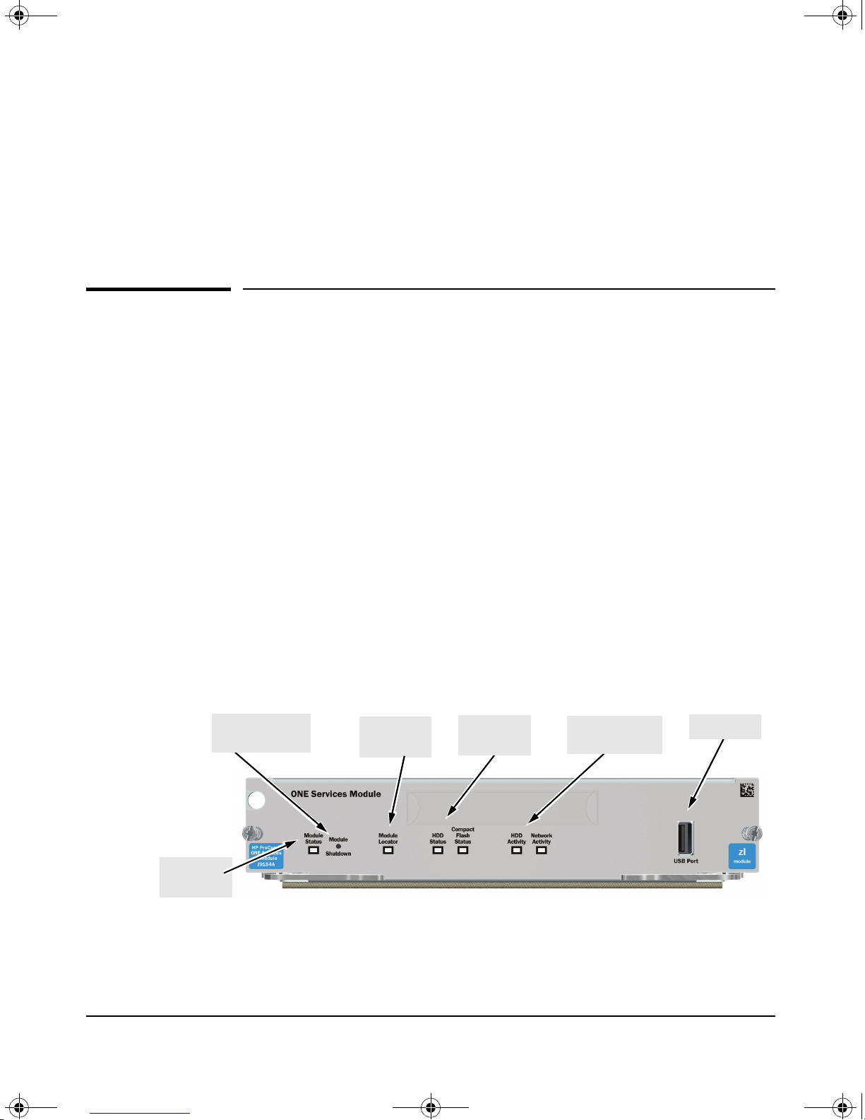
Module
Shutdown button
Module
Locator LED
HDD and CF
Status LEDs
HDD and Network
activity LEDs
USB port
Module
Status LED
zlSM .book Page 1 Thursday, January 29, 2009 11:53 AM
Hardware Installation
Module Overview
The Services Module, an HP ProCurve zl module, is an x86 platform designed
to integrate network applications within the HP ProCurve switch architecture.
By integrating with HP ProCurve's Services library, these applications can
offer more value than stand-alone appliances. The module provides services
to download, install, and license customers’ own applications through the
network.
Hardware Installation
Module Overview
1
The module is managed through an easy to use Command Line Interface (CLI).
The module can be installed in any HP ProCurve zl switch (either the switch
series 5400zl or 8212zl). A maximum of four Services Modules can be installed
in the same chassis. See “Environmental Specifications” on page 1-5.
The Services Module requires switch software version K.13.51 or later to be
installed in the switch.
The following figure shows the front panel of the Services Module.
Figure 1-1. Front panel of the Services Module
1-1
zlSM .book Page 2 Thursday, January 29, 2009 11:53 AM
Hardware Installation
Installing the Module
For a description of the front panel buttons and LEDs, see Table C-1 on page
C-1 in the Web version of this document at www. procurve.com/manuals.
Note The printed version of this document contains the basic information needed
to get you started using the Services Module. It also contains EMC Regulatory
Statements (Appendix A) and Waste Electrical and Electronic Equipment
(WEEE) Statements (Appendix B). Appendices C and D are only in the Web
version of this document at www. procurve.com/manuals. Appendix C gives
more detailed hardware information, and Appendix D gives more detailed
software information.
Installing the Module
Installation Precautions
■ Static electricity can severely damage the electronic components on the
module. When handling and installing the module, follow these procedures to avoid damage from static electricity:
• Handle the module by its bulkhead or edges and avoid touching the
components and the circuitry on the board.
• When installing the module, equalize any static charge difference
between your body and the switch by wearing a grounding wrist
strap and attaching it to the switch’s metal body, or by frequently
touching the switch’s metal body.
■ The module has “low-force”, high-performance connectors. High inser-
tion forces are not necessary to install the module, and should not be
used.
■ Ensure the module is fully inserted. Press the module into the slot
until the bulkhead on the module contacts or is very close to contacting
the front face of the switch chassis.
■ Once the module is fully inserted, screw in the two retaining screws to
secure the module in place.
■ For safe operation, proper switch cooling, and reduction of electromag-
netic emissions, ensure that a slot cover is installed on any unused
module slot. For safety, no more than one slot should be uncovered at a
time when the switch is powered on.
■ Check the temperature specifications for the module; different modules
have different temperature requirements.
To install the module into a switch, the switch can be powered on or off. The
following procedure assumes the switch is powered on.
1-2
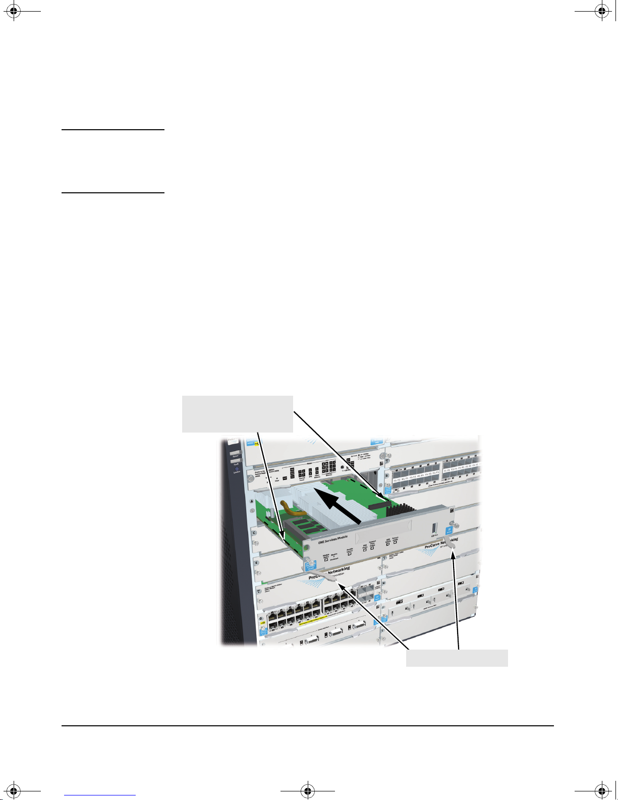
Insert module into the guide s
and slide in until fully
inserted.
Open extractor handles
zlSM .book Page 3 Thursday, January 29, 2009 11:53 AM
Installation Procedure
Note Before installing the Services Module, confirm that the switch has the most
current version of module-compatible software installed. Otherwise the
switch will not recognize the Services Module. For directions on how to check
the switch software version, see “Initial Configuration” on page 2-3.
1. Use a Torx T-10 or flat-bladed screwdriver to unscrew the screws in the
cover plate over the slot where the module is to be installed. Remove the
cover, and store the cover plate for possible future use.
2. Hold the module by its bulkhead, taking care not to touch the metal
connectors or components on the board.
3. Open the extractor handles.
Hardware Installation
Installing the Module
4. Insert the module aligning with the guides in the slot, and slide it into the
slot until it is fully inserted.
5. Once the module is fully inserted, use the extractor handles to seat it
completely.
6. Tighten the screws.
Figure 1-2. Module being installed
1-3
zlSM .book Page 4 Thursday, January 29, 2009 11:53 AM
Hardware Installation
Installing the Module
The procedure to replace or remove a Services Module is described on page
C-5 in the Web version of this document at www. procurve.com/manuals.
Appendix C also describes the procedure to replace the module’s Hard Disk
Drive (HDD) and the Compact Flash (CF) card.
Verifying that the Module is Installed Correctly
When the module is installed, it undergoes a self test that takes a few seconds.
This happens both when the switch is powered on after installing the module,
and when the module is installed while the switch already has power. The
LEDs help determine if the module has passed the self test, as described in
the table below.
LED Behavior
LED Location
of LED
Te st Switch ON briefly while the module is undergoing self test, then OFF.
Fault Switch OFF
Module
Status
Module
Status
HDD and CF
Status
Switch The LED goes ON as soon as the module is installed and the
Services
Module
Services
Module
Display for a Properly Installed Module
Note: If the module was installed with the switch powered off,
and then the switch was powered on, the Test LED will stay ON
for the duration of the switch self test.
Figure C-3 and Figure C-4 show the location of the Test, Fault, and
Module Status LEDs on a 5400zl or 8212zl series switch,
respectively.
switch is powered on, and stays ON steadily.
The LED flashes green while the OS is initializing and goes solid
when the Service OS or product is ready.
Figure 1-1 shows the location of all module LEDs.
The LED goes ON when HDD/CF initialization was successful. It
is OFF by default.
Error Conditions
Error conditions indicated by the module LEDs are described in Table C-1 on
page C-1 in the Web version of this document at www. procurve.com/manuals.
1-4
zlSM .book Page 5 Thursday, January 29, 2009 11:53 AM
Environmental Specifications
Hardware Installation
Environmental Specifications
Temperature Operating
0°C to 40°C (32°F to 104°F)
Relative humidity
(non-condensing)
Maximum altitude 3.0 km (10,000 ft) 4.6 km (15,000 ft)
15% to 90% at 40°C (104°F) 15% to 90% at 65°C (149°F)
Non-Operating
a
-10°C to 65°C (-10°F to 149°F)
a. A maximum of four Service Modules are supported in either a
5400z1 or a 8212zl chassis. For the 5400zl chassis, the maximum
supported temperature is 50°C when there are no Service Modules
in the right side of the chassis, and 40°C if there are Service
Modules in the right hand side of the chassis. The 8212zl chassis
is always limited to 40°C.
Note that the 5406zl chassis only has three left hand slots. This
allows the chassis to be operated at up to 50°C with up to three
Service Modules installed. Installing a fourth Service Module
requires that one of the modules be installed in the right side of
the chassis thereby de-rating the chassis to 40°C.
1-5

zlSM .book Page 6 Thursday, January 29, 2009 11:53 AM
Hardware Installation
Environmental Specifications
1-6
zlSM .book Page 1 Thursday, January 29, 2009 11:53 AM
Getting Started
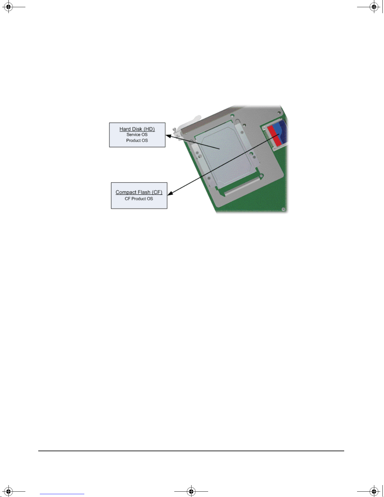
When the Services Module is shipped, it includes the hardware along with the
HP ProCurve Service Operating System (OS). The primary Service OS resides
on a Hard Disk (HD). To recover and diagnose hard disk problems and to
reinstall the HD Service OS, a failsafe Service OS is provided on the Compact
Flash (CF). The CF Service OS is a backup of the HD Service OS. The Service
OS can only be updated from the CF Service OS and vice versa. In this
document, the HD Service OS is simply referred to as the Service OS.
Getting Started
2
The Services Module does not ship with any product software installed. When
the module is installed in a switch for the first time, the system boots directly
into the Service OS. From here, HP ProCurve certified product software can
be downloaded, installed, and activated on the module. Product software
includes both the application and the product OS.
Once a product has been activated, the system can boot directly into the
product OS by using the boot product CLI command. After this the system
will boot directly into the product OS whenever the module is brought up.
Once the module has booted into the product OS, it is completely controlled
through the product OS. The Service OS and the CF Service OS no longer
control it.
2-1
zlSM .book Page 2 Thursday, January 29, 2009 11:53 AM
Getting Started
The figure below shows where the three different operating systems reside on
the Services Module. Note that the Service OS and the product OS live in
independent partitions on the hard disk.
Figure 2-1. Module Operating Systems
CLI commands are available to boot the module from one OS to another. The
following examples show the CLI commands to switch between operating
systems. “:CF” means the module is booted to the CF service OS, “:HD” means
the module is booted to the Service OS, and “:PR” means the module is booted
to the product OS.
Service OS to product OS:
hostswitch(services-module-C:HD)# boot product
Service OS to CF Service OS:
hostswitch(services-module-C:HD)# boot cf_service
Product OS to Service OS:
hostswitch(services-module-C:PR)# boot service
2-2
zlSM .book Page 3 Thursday, January 29, 2009 11:53 AM
Initial Configuration
The Command Line Interface (CLI) must be used to carry out the steps
required to configure the module.
The module CLI is accessed through the switch CLI, and is available in all three
OS environments: Service OS, CF Service OS, and product OS (limited
command set).
Updating Switch Software
Before configuring the Services Module, access the switch CLI to verify the
switch has the most current module-compatible software installed. Use the
following command to check the software version:
Getting Started
Initial Configuration
hostswitch# show version
Image stamp: ...
<
K.13.XX
...
Boot Image: Secondary
If a software update is needed, follow the instructions on page D-1 in the Web
version of this document at www. procurve.com/manuals.
When the switch has the correct software version installed, use the following
CLI command to check if the Services Module is installed:
hostswitch# show modules
The above command shows all the Services Modules installed in the switch,
and their slot numbers.
To get more detailed information about the Service Module status and any
installed application use the following command for a module in slot ‘C’:
hostswitch# show services c details
date, time
>
2-3
Status and Counters - Services Module C Status
HP Services zl Module J9154A
Versions : A.01.06, B.01.03
Current status : running
Description Version Status
--------------- ------------------- -------- Services zl Module B.01.03 running
Application J0000 0.5 licensed
zlSM .book Page 4 Thursday, January 29, 2009 11:53 AM
Getting Started
Initial Configuration
An example output from this command looks as follows:
Updating Services Module Software
The Services Module maintains a repository of the software images that are
downloaded to it. The installation of software depends on the image type.
There are four image types:
■ Service image
■ CF Service image
■ Product image
■ Tools image
The Service, CF Service, and product images are containers for full OS
installations, and are referred to as OS images. These images are generally
large in size, typically greater than 200MB. The OS images don't change
frequently and are usually only used for recovery or major version updates or
to fix major OS problems.
Tools images, used to update the Service and CF tools, and to resolve minor
OS problems, are much smaller, usually 1-5MB. They change more frequently
and contain incremental updates.
There are two installation commands:
■ Install
■ Update
The install command is used for new installations of an OS image. Before a
new OS can be installed, the existing OS must be removed by using the
uninstall command. In addition, the product must also be uninstalled.
2-4

Services Module Agent
Version: B.01.03.4
Build date: Aug 05 2008 18:30:04
BIOS: HP01R101
EEPROM: 0001
OPTROM: A.01.06
Running: ServiceOS
-------------- Product ----------------J0000 App version 0.5
Description: App
Build Date: Aug 01 2008 23:16
-------------- ServiceOS --------------J9154A ServiceOS version 1.0.080508
Description: HD Service OS
Build Date: Aug 05 2008 19:01
Components: HDCHAIN_080508 HDSOS_080508 TOOLS_080508 HDDATA_080508
Tools: "$Revision: #5 $ $DateTime: 2008/08/05 11:12:35 $"
-------------- CF_ServiceOS -----------J9154A CF_ServiceOS version 1.0.080508
Description: CF Service OS
Build Date: Aug 05 2008 19:00
Components: CFCHAIN_080508 CFSOS_080508 TOOLS_080508 CFDATA_080508
Tools: "$Revision: #5 $ $DateTime: 2008/08/05 11:12:35 $"
zlSM .book Page 5 Thursday, January 29, 2009 11:53 AM
The update command is used to modify an existing installation, either an OS
or the Tools. The update is done “in-place” without requiring an uninstall of
the OS. The partition sizes of the new and current OS must match, otherwise
the update command will display an error and abort the process. Updating an
existing Service OS does not require the product to be removed first.
Service OS Installation
Periodically, Service OS updates are available from HP ProCurve. To check
the Service OS version installed on the Services Module, first boot the Service
OS, if it is not already booted. Then, access the module’s Service OS CLI:
hostswitch# services c 1
Then, use the following CLI command:
Getting Started
Initial Configuration
hostswitch(services-module-C:HD)# show version
This command will show the version number for both the Service OS and the
CF Service OS. It will also show the version number of the installed product
(if any). Here is an example output from this command:
2-5
 Loading...