

Page 1
access security guide
hp procurve
switch 2650 and switch 6108
www.hp.com/go/hpprocurve
Page 2

Page 3

!FishSecurity.book Page i Thursday, October 10, 2002 9:19 PM
HP Procurve Switches 2650 and
6108
Access Security Guide
Software Release H.07.01 or Greater
Page 4

!FishSecurity.book Page ii Thursday, October 10, 2002 9:19 PM
© Copyright 2001-2002 Hewlett-Packard Company
All Rights Reserved.
This document contains information which is protected by
copyright. Reproduction, adaptation, or translation without
prior permission is prohibited, except as allowed under the
copyright laws.
Publication Number
5990-3063
October 2002
Edition 1
Applicable Product
HP Procurve Switch 2650 (J4899A)
HP Procurve Switch 6108 (J4902A)
Trademark Credits
Microsoft, Windows, Windows 95, and Microsoft Windows
NT are registered trademarks of Microsoft Corporation.
Internet Explorer is a trademark of Microsoft Corporation.
Ethernet is a registered trademark of Xerox Corporation.
Netscape is a regist ered trademark of Netscape Corporation.
Cisco® is a trademark of Cisco Systems, Inc.
Disclaimer
The information contained in this document is subject to
change without notice.
HEWLETT-PACKARD COMPANY MAKES NO WARRANTY
OF ANY KIND WITH REGARD TO THIS MATERIAL,
INCLUDING, BUT NOT LIMITED TO, THE IMPLIED
WARRANTIES OF MERCHANTABILITY AND FITNESS
FOR A PARTICULAR PURPOSE. Hewlett-Packard shall not
be liable for errors contained herein or for incidental or
consequential damages in connection with the furnishing,
performance, or use of this material.
Hewlett-Packard assumes no responsibility for the use or
reliability of its software on equipment that is not furnished
by Hewlett-Packard.
Warranty
See the Customer Support/Warranty booklet included with
the product.
A copy of the specific warranty terms applicable to your
Hewlett-Packard products and replacement parts can be
obtained from your HP Sales and Service Office or
authorized dealer.
Hewlett-Packard Company
8000 Foothills Boulevard, m/s 5551
Roseville, California 95747-5551
http://www.hp.com/go/hpprocurve
Page 5

!FishSecurity.book Page iii Thursday, October 10, 2002 9:19 PM
Contents
Getting Started
Contents . . . . . . . . . . . . . . . . . . . . . . . . . . . . . . . . . . . . . . . . . . . . . . . . . . . . . . . ix
Introduction . . . . . . . . . . . . . . . . . . . . . . . . . . . . . . . . . . . . . . . . . . . . . . . . . . . x
Overview of Access Security Features . . . . . . . . . . . . . . . . . . . . . . . . . . . x
Command Syntax Conventions . . . . . . . . . . . . . . . . . . . . . . . . . . . . . . . . . . xi
Command Prompts . . . . . . . . . . . . . . . . . . . . . . . . . . . . . . . . . . . . . . . . . . xii
Screen Simulations . . . . . . . . . . . . . . . . . . . . . . . . . . . . . . . . . . . . . . . . . . xii
Related Publications . . . . . . . . . . . . . . . . . . . . . . . . . . . . . . . . . . . . . . . . . . xiii
Getting Documentation From the Web . . . . . . . . . . . . . . . . . . . . . . . . . . xv
Sources for More Information . . . . . . . . . . . . . . . . . . . . . . . . . . . . . . . . . xvi
Need Only a Quick Start? . . . . . . . . . . . . . . . . . . . . . . . . . . . . . . . . . . . . . xvii
To Set Up and Install the Switch in Your Network . . . . . . . . . . . . . . . xvii
1 Configuring Username and Password Security
Contents . . . . . . . . . . . . . . . . . . . . . . . . . . . . . . . . . . . . . . . . . . . . . . . . . . . . . . 1-1
Overview . . . . . . . . . . . . . . . . . . . . . . . . . . . . . . . . . . . . . . . . . . . . . . . . . . . . . 1-2
Configuring Local Password Security . . . . . . . . . . . . . . . . . . . . . . . . . . . 1-4
Menu: Setting Passwords . . . . . . . . . . . . . . . . . . . . . . . . . . . . . . . . . . . . . 1-4
CLI: Setting Passwords and Usernames . . . . . . . . . . . . . . . . . . . . . . . . . 1-5
Web: Setting Passwords and Usernames . . . . . . . . . . . . . . . . . . . . . . . . 1-6
iii
Page 6

!FishSecurity.book Page iv Thursday, October 10, 2002 9:19 PM
2 TACACS+ Authentication
Contents . . . . . . . . . . . . . . . . . . . . . . . . . . . . . . . . . . . . . . . . . . . . . . . . . . . . . . 2-1
Overview . . . . . . . . . . . . . . . . . . . . . . . . . . . . . . . . . . . . . . . . . . . . . . . . . . . . . 2-2
Terminology Used in TACACS Applications: . . . . . . . . . . . . . . . . . . . . 2-4
General System Requirements . . . . . . . . . . . . . . . . . . . . . . . . . . . . . . . . . 2-5
General Authentication Setup Procedure . . . . . . . . . . . . . . . . . . . . . . . 2-6
Configuring TACACS+ on the Switch . . . . . . . . . . . . . . . . . . . . . . . . . . . 2-9
Before You Begin . . . . . . . . . . . . . . . . . . . . . . . . . . . . . . . . . . . . . . . . . . . . 2-9
CLI Commands Described in this Section . . . . . . . . . . . . . . . . . . . . . . . 2-9
Viewing the Switch’s Current Authentication Configuration . . . . . . 2-10
Viewing the Switch’s Current TACACS+ Configuration . . . . . . . . . . 2-10
Configuring the Switch’s Authentication Methods . . . . . . . . . . . . . . . 2-11
Configuring the Switch’s TACACS+ Server Access . . . . . . . . . . . . . . 2-15
How Authentication Operates . . . . . . . . . . . . . . . . . . . . . . . . . . . . . . . . . 2-20
General Authentication Process Using a TACACS+ Server . . . . . . . . 2-20
Local Authentication Process . . . . . . . . . . . . . . . . . . . . . . . . . . . . . . . . 2-22
Using the Encryption Key . . . . . . . . . . . . . . . . . . . . . . . . . . . . . . . . . . . 2-23
General Operation . . . . . . . . . . . . . . . . . . . . . . . . . . . . . . . . . . . . . . 2-23
Encryption Options in the Switch . . . . . . . . . . . . . . . . . . . . . . . . . 2-23
Controlling Web Browser Interface Access When Using TACACS+
Authentication . . . . . . . . . . . . . . . . . . . . . . . . . . . . . . . . . . . . . . . . . . . . . . . 2-24
Messages Related to TACACS+ Operation . . . . . . . . . . . . . . . . . . . . . 2-25
Operating Notes . . . . . . . . . . . . . . . . . . . . . . . . . . . . . . . . . . . . . . . . . . . . . . 2-25
3 RADIUS Authentication and Accounting
Contents . . . . . . . . . . . . . . . . . . . . . . . . . . . . . . . . . . . . . . . . . . . . . . . . . . . . . . 3-1
Overview . . . . . . . . . . . . . . . . . . . . . . . . . . . . . . . . . . . . . . . . . . . . . . . . . . . . . 3-2
Terminology . . . . . . . . . . . . . . . . . . . . . . . . . . . . . . . . . . . . . . . . . . . . . . . . . . 3-3
Switch Operating Rules for RADIUS . . . . . . . . . . . . . . . . . . . . . . . . . . . . 3-4
General RADIUS Setup Procedure . . . . . . . . . . . . . . . . . . . . . . . . . . . . . 3-5
iv
Preparation: . . . . . . . . . . . . . . . . . . . . . . . . . . . . . . . . . . . . . . . . . . . . 3-5
Page 7

!FishSecurity.book Page v Thursday, October 10, 2002 9:19 PM
Configuring the Switch for RADIUS Authentication . . . . . . . . . . . . . 3-6
Outline of the Steps for Configuring RADIUS Authentication . . . . . . 3-6
1. Configure Authentication for the Access Methods You Want RADIUS
To Protect . . . . . . . . . . . . . . . . . . . . . . . . . . . . . . . . . . . . . . . . . . . . . . . . . . 3-8
2. Configure the Switch To Access a RADIUS Server . . . . . . . . . . . . 3-10
3. Configure the Switch’s Global RADIUS Parameters . . . . . . . . . . . 3-12
Local Authentication Process . . . . . . . . . . . . . . . . . . . . . . . . . . . . . . . . . 3-14
Controlling Web Browser Interface Access When Using RADIUS
Authentication . . . . . . . . . . . . . . . . . . . . . . . . . . . . . . . . . . . . . . . . . . . . . . . 3-15
Configuring RADIUS Accounting . . . . . . . . . . . . . . . . . . . . . . . . . . . . . . 3-16
Operating Rules for RADIUS Accounting . . . . . . . . . . . . . . . . . . . . . . 3-17
Steps for Configuring RADIUS Accounting . . . . . . . . . . . . . . . . . . . . . 3-18
1. Configure the Switch To Access a RADIUS Server . . . . . . . . . 3-19
2. Configure Accounting Types and the Controls for Sending
Reports to the RADIUS Server . . . . . . . . . . . . . . . . . . . . . . . . . 3-20
3. (Optional) Configure Session Blocking and Interim
Updating Options . . . . . . . . . . . . . . . . . . . . . . . . . . . . . . . . . . . . 3-22
Viewing RADIUS Statistics . . . . . . . . . . . . . . . . . . . . . . . . . . . . . . . . . . . . 3-23
General RADIUS Statistics . . . . . . . . . . . . . . . . . . . . . . . . . . . . . . . . . . . 3-23
RADIUS Authentication Statistics . . . . . . . . . . . . . . . . . . . . . . . . . . . . . 3-25
RADIUS Accounting Statistics . . . . . . . . . . . . . . . . . . . . . . . . . . . . . . . . 3-26
Changing RADIUS-Server Access Order . . . . . . . . . . . . . . . . . . . . . . . 3-27
Messages Related to RADIUS Operation . . . . . . . . . . . . . . . . . . . . . . . 3-29
4 Configuring Secure Shell (SSH)
Contents . . . . . . . . . . . . . . . . . . . . . . . . . . . . . . . . . . . . . . . . . . . . . . . . . . . . . . 4-1
Overview . . . . . . . . . . . . . . . . . . . . . . . . . . . . . . . . . . . . . . . . . . . . . . . . . . . . . 4-2
Terminology . . . . . . . . . . . . . . . . . . . . . . . . . . . . . . . . . . . . . . . . . . . . . . . . . . 4-4
Prerequisite for Using SSH . . . . . . . . . . . . . . . . . . . . . . . . . . . . . . . . . . . . 4-5
Public Key Format Requirement . . . . . . . . . . . . . . . . . . . . . . . . . . . . . . . 4-5
Steps for Configuring and Using SSH for Switch and Client
Authentication . . . . . . . . . . . . . . . . . . . . . . . . . . . . . . . . . . . . . . . . . . . . . . . . 4-6
General Operating Rules and Notes . . . . . . . . . . . . . . . . . . . . . . . . . . . . 4-8
Configuring the Switch for SSH Operation . . . . . . . . . . . . . . . . . . . . . . 4-9
v
Page 8

!FishSecurity.book Page vi Thursday, October 10, 2002 9:19 PM
1. Assigning Local Operator and Manager Passwords . . . . . . . . . . . . . 4-9
2. Generating the Switch’s Public and Private Key Pair . . . . . . . . . . 4-10
3. Providing the Switch’s Public Key to Clients . . . . . . . . . . . . . . . . . . 4-12
4. Enabling SSH on the Switch and Anticipating SSH
Client Contact Behavior . . . . . . . . . . . . . . . . . . . . . . . . . . . . . . . . . . 4-15
5. Configuring the Switch for SSH Authentication . . . . . . . . . . . . . . . 4-18
6. Use an SSH Client To Access the Switch . . . . . . . . . . . . . . . . . . . . . 4-21
MoreInformation on SSH Client Public-Key Authentication . . . . 4-21
Messages Related to SSH Operation . . . . . . . . . . . . . . . . . . . . . . . . . . . 4-26
5 Configuring Port-Based Access Control (802.1x)
Contents . . . . . . . . . . . . . . . . . . . . . . . . . . . . . . . . . . . . . . . . . . . . . . . . . . . . . . 5-1
Overview . . . . . . . . . . . . . . . . . . . . . . . . . . . . . . . . . . . . . . . . . . . . . . . . . . . . . 5-2
Why Use Port-Based Access Control? . . . . . . . . . . . . . . . . . . . . . . . . . . 5-2
General Features . . . . . . . . . . . . . . . . . . . . . . . . . . . . . . . . . . . . . . . . . . . . 5-2
How 802.1x Operates . . . . . . . . . . . . . . . . . . . . . . . . . . . . . . . . . . . . . . . . . . 5-4
Authenticator Operation . . . . . . . . . . . . . . . . . . . . . . . . . . . . . . . . . . . . . 5-4
Switch-Port Supplicant Operation . . . . . . . . . . . . . . . . . . . . . . . . . . . . . 5-5
Terminology . . . . . . . . . . . . . . . . . . . . . . . . . . . . . . . . . . . . . . . . . . . . . . . . . . 5-6
General Operating Rules and Notes . . . . . . . . . . . . . . . . . . . . . . . . . . . . 5-7
Setup Procedure for Port-Based Access Control (802.1x) . . . . . . . 5-8
Before You Begin . . . . . . . . . . . . . . . . . . . . . . . . . . . . . . . . . . . . . . . . . . . . 5-8
Overview: Configuring 802.1x Authentication on the Switch . . . . . . . 5-9
Configuring Switch Ports as 802.1x Authenticators . . . . . . . . . . . . 5-10
1. Disable LACP on the Ports Selected for 802.1x Access . . . . . . . . . 5-10
2. Enable 802.1x Authentication on Selected Ports . . . . . . . . . . . . . . 5-11
3. Configure the 802.1x Authentication Method . . . . . . . . . . . . . . . . . 5-13
4. Enter the RADIUS Host IP Address(es) . . . . . . . . . . . . . . . . . . . . . . 5-14
5. Optional: For Authenticator Ports, Configure Port-
Security To Allow Only 802.1x Devices . . . . . . . . . . . . . . . . . . . . . . 5-15
6. Enable 802.1x Authentication on the Switch . . . . . . . . . . . . . . . . . . 5-16
Configuring Switch Ports To Operate As Supplicants for 802.1x
Connections to Other Switches . . . . . . . . . . . . . . . . . . . . . . . . . . . . . . . 5-17
vi
Page 9

!FishSecurity.book Page vii Thursday, October 10, 2002 9:19 PM
Displaying 802.1x Configuration, Statistics, and Counters . . . . . . 5-21
Show Commands for Port-Access Authenticator . . . . . . . . . . . . . . . . 5-21
Show Commands for Port-Access Supplicant . . . . . . . . . . . . . . . . . . . 5-23
How 802.1x Authentication Affects VLAN Operation . . . . . . . . . . . 5-24
Static VLAN Requirement . . . . . . . . . . . . . . . . . . . . . . . . . . . . . . . . 5-24
Messages Related to 802.1x Operation . . . . . . . . . . . . . . . . . . . . . . . . 5-28
6 Configuring and Monitoring Port Security
Contents . . . . . . . . . . . . . . . . . . . . . . . . . . . . . . . . . . . . . . . . . . . . . . . . . . . . . . 6-1
Overview . . . . . . . . . . . . . . . . . . . . . . . . . . . . . . . . . . . . . . . . . . . . . . . . . . . . . 6-2
Basic Operation . . . . . . . . . . . . . . . . . . . . . . . . . . . . . . . . . . . . . . . . . . . . . . . 6-2
Blocking Unauthorized Traffic . . . . . . . . . . . . . . . . . . . . . . . . . . . . . 6-3
Trunk Group Exclusion . . . . . . . . . . . . . . . . . . . . . . . . . . . . . . . . . . . 6-4
Planning Port Security . . . . . . . . . . . . . . . . . . . . . . . . . . . . . . . . . . . . . . . . 6-5
Port Security Command Options and Operation . . . . . . . . . . . . . . . . . 6-6
Retention of Static Addresses . . . . . . . . . . . . . . . . . . . . . . . . . . . . . . . . . 6-8
Displaying Current Port Security Settings . . . . . . . . . . . . . . . . . . . . . . . 6-9
Configuring Port Security . . . . . . . . . . . . . . . . . . . . . . . . . . . . . . . . . . . . 6-10
Web: Displaying and Configuring Port Security Features . . . . . . . 6-15
Reading Intrusion Alerts and Resetting Alert Flags . . . . . . . . . . . . 6-15
Notice of Security Violations . . . . . . . . . . . . . . . . . . . . . . . . . . . . . . . . . 6-15
How the Intrusion Log Operates . . . . . . . . . . . . . . . . . . . . . . . . . . . . . . 6-16
Keeping the Intrusion Log Current by Resetting Alert Flags . . . . . . . 6-17
Menu: Checking for Intrusions, Listing Intrusion Alerts, and
Resetting Alert Flags . . . . . . . . . . . . . . . . . . . . . . . . . . . . . . . . . . . . 6-17
CLI: Checking for Intrusions, Listing Intrusion Alerts, and
Resetting Alert Flags . . . . . . . . . . . . . . . . . . . . . . . . . . . . . . . . . . . 6-19
Using the Event Log To Find Intrusion Alerts . . . . . . . . . . . . . . . 6-21
Web: Checking for Intrusions, Listing Intrusion Alerts, and
Resetting Alert Flags . . . . . . . . . . . . . . . . . . . . . . . . . . . . . . . . . . . 6-22
Operating Notes for Port Security . . . . . . . . . . . . . . . . . . . . . . . . . . . . . 6-22
vii
Page 10

!FishSecurity.book Page viii Thursday, October 10, 2002 9:19 PM
7 Using Authorized IP Managers
Contents . . . . . . . . . . . . . . . . . . . . . . . . . . . . . . . . . . . . . . . . . . . . . . . . . . . . . . 7-1
Overview . . . . . . . . . . . . . . . . . . . . . . . . . . . . . . . . . . . . . . . . . . . . . . . . . . . . . 7-2
Options . . . . . . . . . . . . . . . . . . . . . . . . . . . . . . . . . . . . . . . . . . . . . . . . . . . . . . . 7-3
Access Levels . . . . . . . . . . . . . . . . . . . . . . . . . . . . . . . . . . . . . . . . . . . . . . . . . 7-3
Defining Authorized Management Stations . . . . . . . . . . . . . . . . . . . . . 7-4
Overview of IP Mask Operation . . . . . . . . . . . . . . . . . . . . . . . . . . . . . . . 7-4
Menu: Viewing and Configuring IP Authorized Managers . . . . . . . . . . 7-5
CLI: Viewing and Configuring Authorized IP Managers . . . . . . . . . . . . 7-6
Listing the Switch’s Current Authorized IP Manager(s) . . . . . . . . 7-6
Configuring IP Authorized Managers for the Switch . . . . . . . . . . 7-7
Web: Configuring IP Authorized Managers . . . . . . . . . . . . . . . . . . . . . . 7-8
Building IP Masks . . . . . . . . . . . . . . . . . . . . . . . . . . . . . . . . . . . . . . . . . . . . . 7-9
Configuring One Station Per Authorized Manager IP Entry . . . . . . . . 7-9
Configuring Multiple Stations Per Authorized Manager IP Entry . . . 7-10
Additional Examples for Authorizing Multiple Stations . . . . . . . . . . 7-12
Operating Notes . . . . . . . . . . . . . . . . . . . . . . . . . . . . . . . . . . . . . . . . . . . . . . 7-12
Index . . . . . . . . . . . . . . . . . . . . . . . . . . . . . . . . . . . . . . . . . . . . . . . . . . . . Index-1
viii
Page 11

!FishSecurity.book Page ix Thursday, October 10, 2002 9:19 PM
Getting Started
Contents
Introduction . . . . . . . . . . . . . . . . . . . . . . . . . . . . . . . . . . . . . . . . . . . . . . . . . . . . x
Overview of Access Security Features . . . . . . . . . . . . . . . . . . . . . . . . . . . . x
Command Syntax Conventions . . . . . . . . . . . . . . . . . . . . . . . . . . . . . . . . . . xi
Command Prompts . . . . . . . . . . . . . . . . . . . . . . . . . . . . . . . . . . . . . . . . . . . xii
Screen Simulations . . . . . . . . . . . . . . . . . . . . . . . . . . . . . . . . . . . . . . . . . . . xii
Related Publications . . . . . . . . . . . . . . . . . . . . . . . . . . . . . . . . . . . . . . . . . . xiii
Getting Documentation From the Web . . . . . . . . . . . . . . . . . . . . . . . . . . . xv
Sources for More Information . . . . . . . . . . . . . . . . . . . . . . . . . . . . . . . . . xvi
Need Only a Quick Start? . . . . . . . . . . . . . . . . . . . . . . . . . . . . . . . . . . . . . . xvii
ix
Page 12

!FishSecurity.book Page x Thursday, October 10, 2002 9:19 PM
Getting Started
Introduction
Introduction
This Access Security Guide is intended for use with the following switches:
HP Procurve Switch 2650
HP Procurve Switch 6108
Overview of Access Security Features
Local Manager and Operator Passwords (page 1-1)
Control access and privileges for the CLI, menu, and web browser
interface.
TACACS+ Authentication (page 2-1)
Uses an authentication application on a central server to allow or
deny access to Switch 2650 or 6108.
RADIUS Authentication and Accounting (page 3-1)
Like TACACS+, uses an authentication application on a central server
to allow or deny access to Switch 2650 or 6108. RADIUS also provides
accounting services for sending data about user activity and system
events to a RADIUS server.
Secure Shell (SSH) Authentication (page 4-1)
Provides encrypted paths for remote access to switch management
functions.
Port-Based Access Control (802.1x) (page 5-1)
On point-to-point connections, enables the switch to allow or deny
traffic between a port and an 802.1x-aware device (supplicant)
attempting to access the switch. Also enables the switch to operate
as a supplicant for connections to other 802.1x-aware switches.
Port Security (page 6-1)
Enables a switch port to maintain a unique list of MAC addresses
defining which specific devices are allowed to access the network
through that port. Also enables a port to detect, prevent, and log
access attempts by unauthorized devices.
Authorized IP Managers (page 7-1)
Allows access to the switch by a networked device having an IP
address previously configured in the switch as "authorized".
x
Page 13

!FishSecurity.book Page xi Thursday, October 10, 2002 9:19 PM
HP recommends that you use local passwords together with the switch’s other
security features to provide a more comprehensive security fabric than if you
use only the local password option. Table 1 lists these features with the
security coverage they provide.
Table 1. Management Access Security Protection
Getting Started
Overview of Access Security Features
Security Feature Offers Protection Against Unauthorized Client Access to
Switch Management Features
Connection Telne t SNMP
(Net Mgmt)
Local Manager and Operator
Usernames and Passwords*
TAC ACS +*
RADIUS*
SSH
Port-Based Access Control (802.1x)
Port Security (MAC address)
Authorized IP Managers
*Protection for serial port acc ess includes the local Manager/Operator, TACACS+, and RADIUS optio ns (direct connect
or modem access).
PtP: Yes No Ye s Yes No
Remote: Ye s No Ye s Yes No
PtP: Yes No No Yes No
Remote: Ye s No No Yes No
PtP: Yes No No Yes No
Remote: Ye s No No Yes No
Ptp: Yes No No Yes No
Remote: Ye s No No Yes No
PtP: Yes Yes Yes Yes Yes
Remote: No No No No No
PtP: Yes Yes Yes Yes Yes
Remote: Ye s Ye s Ye s Yes Yes
PtP: Yes Yes Yes Yes No
Remote: Ye s Ye s Ye s Yes No
Web
Browser
SSH
Client
Offers Protection
Against
Unauthorized Client
Access to the
Network
There are two security areas to protect: access to the switch management
features and access to the network through the switch. The above table shows
the type of protection each switch security feature offers.
The Product Documentation CD-ROM shipped with the switch includes a
copy of this guide. You can also download the latest copy from the HP
Procurve website. (Refer to “Getting Documentation From the Web”, below.)
xi
Page 14

!FishSecurity.book Page xii Thursday, October 10, 2002 9:19 PM
Getting Started
Command Syntax Conventions
Command Syntax Conventions
This guide uses the following conventions for command syntax and displays.
Syntax: aaa port-access authenticator < port-list >
Vertical bars ( | ) separate alternative, mutually exclusive elements.
Square brackets ( [ ] ) indicate optional elements.
Braces ( < > ) enclose required elements.
Braces within square brackets ( [ < > ] ) indicate a required element within
an optional choice.
Boldface indicates use of a CLI command, part of a CLI command syntax,
or other displayed element in general text. For example:
[ control < authorized | auto | unauthorized >]
“Use the copy tftp command to download the key from a TFTP server.”
Italics indicate variables for which you must supply a value when executing the command. For example, in this command syntax, you must provide
one or more port numbers:
Syntax: aaa port-access authenticator < port-list >
Command Prompts
In the default configuration, your Switch 2650 or 6108 displays one of the
following CLI prompts:
HP Procurve Switch 2650#
HP Procurve Switch 6108#
To simplify recognition, this guide uses HPswitch to represent command
prompts for all models. That is:
HPswitch#
(You can use the hostname command to change the text in the CLI prompt.)
Screen Simulations
Figures containing simulated screen text and command output look like this:
xii
Page 15

!FishSecurity.book Page xiii Thursday, October 10, 2002 9:19 PM
Figure 1. Example of a Figure Showing a Simulated Screen
In some cases, brief command-output sequences appear without figure identification. For example:
HPswitch(config)# clear public-key
HPswitch(config)# show ip client-public-key
show_client_public_key: cannot stat keyfile
Getting Started
Related Publications
Related Publications
Product Notes and Software Update Information. The Read Me First
shipped with your switch provides software update information, product
notes, and other information. A printed copy is shipped with your switch. For
the latest version, refer to “Getting Documentation From the Web” on page xv.
Installation and Getting Started Guide. Use the Installation and Get-
ting Started Guide shipped with your switch to prepare for and perform the
physical installation. This guide also steps you through connecting the switch
to your network and assigning IP addressing, as well as describing the LED
indications for correct operation and trouble analysis. A PDF version of this
guide is also provided on the Product Documentation CD-ROM shipped with
the switch. And you can download a copy from the HP Procurve website. (See
“Getting Documentation From the Web” on page xv.)
Management and Configuration Guide. Use the Management and Con-
figuration Guide for information on:
Using the command line interface (CLI), Menu interface, and web browser
interface
Learning the operation and configuration of all switch software features
other than the access security features included in this guide
Troubleshooting software operation
HP provides a PDF version of this guide on the Product Documentation
CD-ROM shipped with the switch. You can also download the latest copy from
the HP Procurve website. (See “Getting Documentation From the Web” on
page xv.)
xiii
Page 16

!FishSecurity.book Page xiv Thursday, October 10, 2002 9:19 PM
Getting Started
Related Publications
Command Line Interface Reference Guide. This guide, available in a
PDF file on the HP Procurve website, provides a summary of the CLI commands generally available for HP Procurve switches. For the latest version,
see “Getting Documentation From the Web” on page xv.
Release Notes. Release notes are posted on the HP Procurve website and
provide information on new software updates:
New features and how to configure and use them
Software management, including downloading software to the switch
Software fixes addressed in current and previous releases
To view and download a copy of the latest release notes for your switch, see
“Getting Documentation From the Web” on page xv.
xiv
Page 17
!FishSecurity.book Page xv Thursday, October 10, 2002 9:19 PM
Getting Documentation From the Web
1. Go to the HP Procurve website at
http://www.hp.com/go/hpprocurve
2. Click on technical support.
3. Click on manuals.
4. Click on the product for which you want to view or download a manual.
Getting Started
Getting Documentation From the Web
3
2
4
xv
Page 18
!FishSecurity.book Page xvi Thursday, October 10, 2002 9:19 PM
Getting Started
Sources for More Information
Sources for More Information
If you need information on specific parameters in the menu interface,
refer to the online help provided in the interface.
Online Help
for Menu
If you need information on a specific command in the CLI, type the
command name followed by “help”. For example:
If you need information on specific features in the HP Web Browser
Interface (hereafter referred to as the “web browser interface”), use the
online help available for the web browser interface. For more information
on web browser Help options, refer to the Management and Configura-
tion Guide for your switch.
If you need further information on Hewlett-Packard switch technology,
visit the HP Procurve website at:
http://www.hp.com/go/hpprocurve
xvi
Page 19

!FishSecurity.book Page xvii Thursday, October 10, 2002 9:19 PM
Need Only a Quick Start?
IP Addressing. If you just want to give the switch an IP address so that it
can communicate on your network, or if you are not using VLANs, HP
recommends that you use the Switch Setup screen to quickly configure IP
addressing. To do so, do one of the following:
Enter setup at the CLI Manager level prompt.
HPswitch# setup
In the Main Menu of the Menu interface, select
8. Run Setup
For more on using the Switch Setup screen, see the Installation and Getting
Started Guide you received with the switch.
Getting Started
Need Only a Quick Start?
To Set Up and Install the Switch in Your Network
Use the HP Procurve Switch 2650 and 6108 Installation and Getting Started
Guide (shipped with the switch) for the following:
Notes, cautions, and warnings related to installing and using the switch
and its related modules
Instructioins for physically installing the switch in your network
Quickly assigning an IP address and subnet mask, set a Manager password, and (optionally) configure other basic features.
xvii
Page 20

!FishSecurity.book Page xviii Thursday, October 10, 2002 9:19 PM
Page 21

!FishSecurity.book Page 1 Thursday, October 10, 2002 9:19 PM
Configuring Username and Password Security
Contents
Overview . . . . . . . . . . . . . . . . . . . . . . . . . . . . . . . . . . . . . . . . . . . . . . . . . . . . . 1-2
Configuring Local Password Security . . . . . . . . . . . . . . . . . . . . . . . . . . . 1-4
Menu: Setting Passwords . . . . . . . . . . . . . . . . . . . . . . . . . . . . . . . . . . . . . 1-4
CLI: Setting Passwords and Usernames . . . . . . . . . . . . . . . . . . . . . . . . . 1-5
Web: Setting Passwords and Usernames . . . . . . . . . . . . . . . . . . . . . . . . 1-6
1
1-1
Page 22

!FishSecurity.book Page 2 Thursday, October 10, 2002 9:19 PM
Configuring Username and Password Security
Overview
Overview
Feature Default Menu CLI Web
Set Usernames no user names set — — page 1-6
Set a Password no passwords set page 1-4 page 1-5 page 1-6
Delete Password
Protection
Console access includes both the menu interface and the CLI. There are two
levels of console access: Manager and Operator. For security, you can set a
password pair (username and password) on each of these levels.
n/a page 1-4 page 1-6 page 1-6
Note Usernames are optional. Also, in the menu interface, you can configure
passwords, but not usernames. To configure usernames, use the CLI or the
web browser interface.
Level Actions Permitted
Manager: Access to all console interface areas.
This is the default level. That is, if a Manager password has not been set prior
to starting the current console session, then anyone having access to the
console can access any area of the console interface.
Operator: Access to the Status and Counters menu, the Event Log, and the CLI*, but no
Configuration capabilities.
On the Operator level, the configuration menus, Download OS, and Reboot
Switch options in the Main Menu are not available.
*Allows use of the ping, link-test, show, menu, exit, and logout commands, plus the enable
command if you can provide the Manager password.
To configure password security:
1. Set a Manager password pair (and an Operator password pair, if applicable
for your system).
2. Exit from the current console session. A Manager password pair will now
be needed for full access to the console.
1-2
Page 23

!FishSecurity.book Page 3 Thursday, October 10, 2002 9:19 PM
If you do steps 1 and 2, above, then the next time a console session is started
for either the menu interface or the CLI, a prompt appears for a password.
Assuming you have protected both the Manager and Operator levels, the level
of access to the console interface will be determined by which password is
entered in response to the prompt.
If you set a Manager password, you may also want to configure the
Inactivity Time parameter. (Refer to the Management and Configuration
Guide for your switch.) This causes the console session to end after the
specified period of inactivity, thus giving you added security against unauthorized console access.
Note The manager and operator passwords and (optional) usernames control
access to the menu interface, CLI, and web browser interface.
Configuring Username and Password Security
Overview
If you configure only a Manager password (with no Operator password), and
in a later session the Manager password is not entered correctly in response
to a prompt from the switch, then the switch does not allow management
access for that session.
If the switch has a password for both the Manager and Operator levels, and
neither is entered correctly in response to the switch’s password prompt, then
the switch does not allow management access for that session.
Passwords are case-sensitive.
Caution If the switch has neither a Manager nor an Operator password, anyone
having access to the switch through either Telnet, the serial port, or the web
browser interface can access the switch with full manager privileges. Also,
if you configure only an Operator password, entering the Operator password enables full manager privileges.
The rest of this section covers how to:
Set passwords
Delete passwords
Recover from a lost password
1-3
Page 24
!FishSecurity.book Page 4 Thursday, October 10, 2002 9:19 PM
Configuring Username and Password Security
Configuring Local Password Security
Configuring Local Password Security
Menu: Setting Passwords
As noted earlier in this section, usernames are optional. Configuring a username requires either the CLI or the web browser interface.
1. From the Main Menu select:
3. Console Passwords
Figure 1-1. The Set Password Screen
2. To set a new password:
a. Select Set Manager Password or Set Operator Password. You will then
be prompted with Enter new password.
b. Type a password of up to 16 ASCII characters with no spaces and
press
c. When prompted with Enter new password again, retype the new pass-
word and press
After you configure a password, if you subsequently start a new console
session, you will be prompted to enter the password. (If you use the CLI or
web browser interface to configure an optional username, the switch will
prompt you for the username, and then the password.)
To Delete Password Protection (Including Recovery from a Lost
Password): This procedure deletes all usernames (if configured) and pass-
words (Manager and Operator).
. (Remember that passwords are case-sensitive.)
.
1-4
Page 25
!FishSecurity.book Page 5 Thursday, October 10, 2002 9:19 PM
If you have physical access to the switch, press and hold the Clear button (on
the front of the switch) for a minimum of one second to clear all password
protection, then enter new passwords as described earlier in this chapter.
If you do not have physical access to the switch, you will need Manager-Level
access:
1. Enter the console at the Manager level.
2. Go to the Set Passwords screen as described above.
3. Select Delete Password Protection. You will then see the following prompt:
Continue Deletion of password protection? No
Configuring Username and Password Security
Configuring Local Password Security
4. Press the Space bar to select Yes, then press
5. Press
to clear the Password Protection message.
.
To Recover from a Lost Manager Password: If you cannot start a console session at the Manager level because of a lost Manager password, you
can clear the password by getting physical access to the switch and pressing
and holding the Clear button for a minimum of one second. This action deletes
all passwords and usernames (Manager and Operator) used by both the
console and the web browser interface.
CLI: Setting Passwords and Usernames
Commands Used in This Section
password See below.
Configuring Manager and Operator Passwords.
Syntax:
[ no ] password <manager | operator > [ user-name ASCII-STR ]
[ no ] password < all >
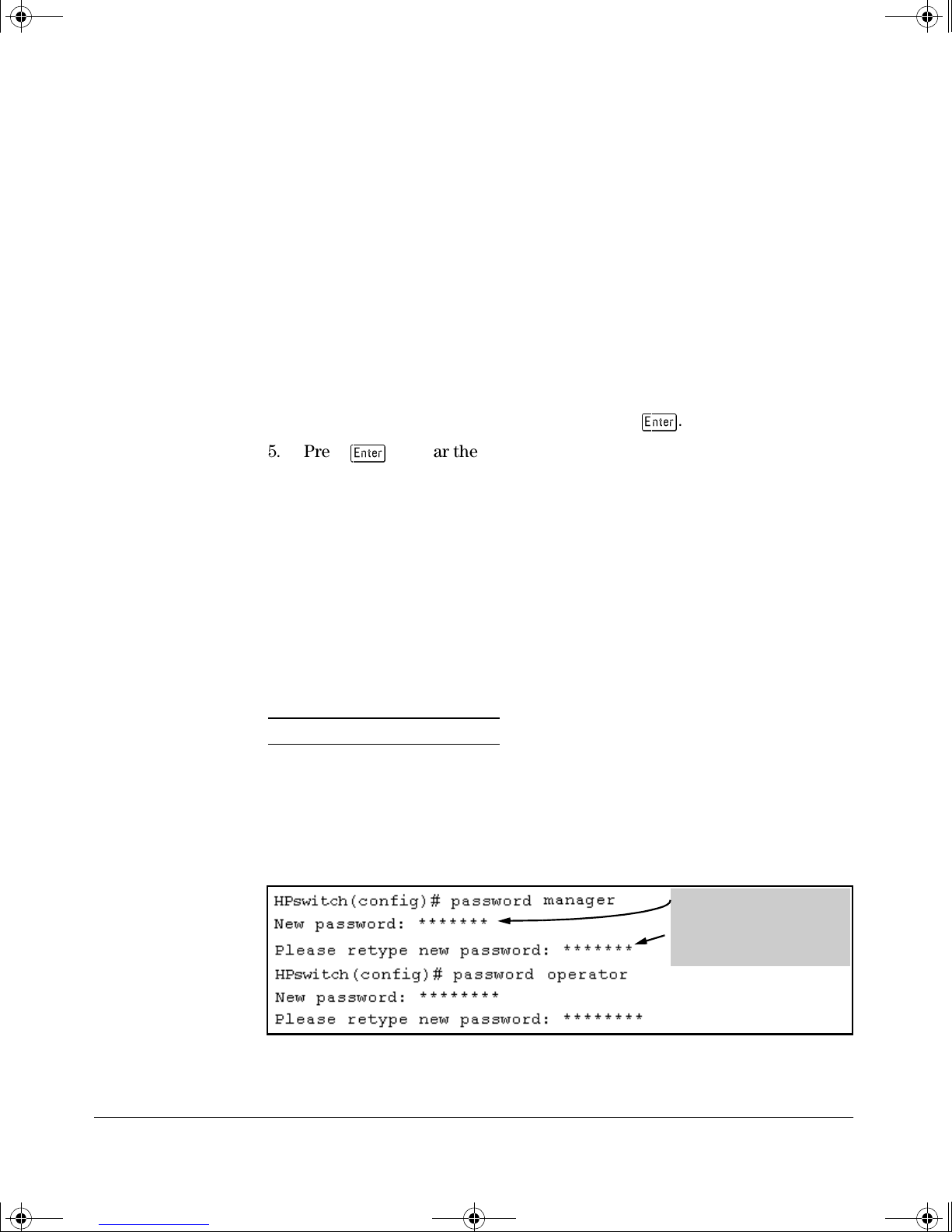
Figure 1-2. Example of Configuring Manager and Operator Passwords
• Password entries appear
as asterisks.
• You must type the
password entry twice.
1-5
Page 26
!FishSecurity.book Page 6 Thursday, October 10, 2002 9:19 PM
Configuring Username and Password Security
Configuring Local Password Security
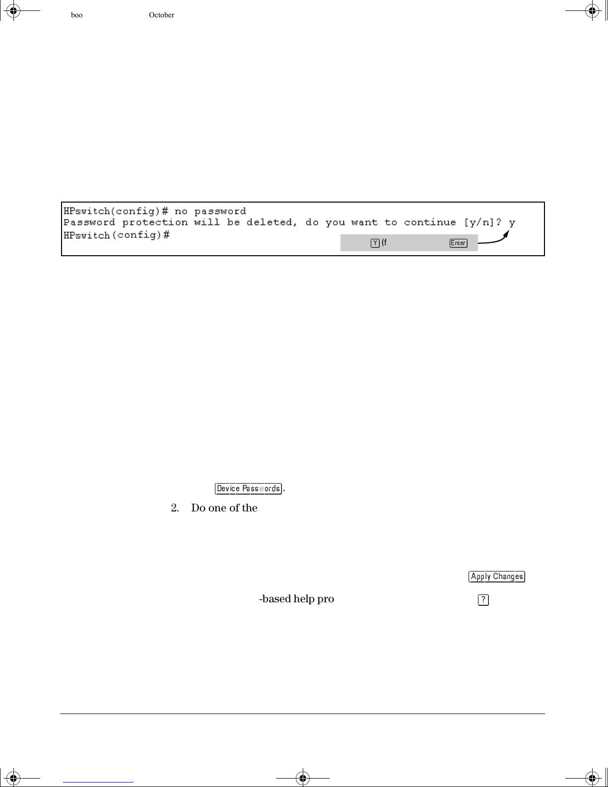
To Remove Password Protection. Removing password protection means
to eliminate password security. This command prompts you to verify that you
want to remove one or both passwords, then clears the indicated password(s).
(This command also clears the username associated with a password you are
removing.) For example, to remove the Operator password (and username, if
assigned) from the switch, you would do the following:
Figure 1-3. Removing a Password and Associated Username from the Switch
The effect of executing the command in figure 1-3 is to remove password
protection from the Operator level. (This means that anyone who can access
the switch console can gain Operator access without having to enter a username or password.)
Press
(for yes) and press
.
Web: Setting Passwords and Usernames
In the web browser interface you can enter passwords and (optional) usernames.
To Configure (or Remove) Usernames and Passwords in the Web
Browser Interface.
1. Click on the
Click on
2. Do one of the following:
• To set username and password protection, enter the usernames and
passwords you want in the appropriate fields.
• To remove username and password protection, leave the fields blank.
3. Implement the usernames and passwords by clicking on
To access the web-based help provided for the switch, click on
browser screen.
Security tab.
.
in the web
.
1-6
Page 27

!FishSecurity.book Page 1 Thursday, October 10, 2002 9:19 PM
TACACS+ Authentication
Contents
Overview . . . . . . . . . . . . . . . . . . . . . . . . . . . . . . . . . . . . . . . . . . . . . . . . . . . . . 2-2
Terminology Used in TACACS Applications: . . . . . . . . . . . . . . . . . . . . 2-4
General System Requirements . . . . . . . . . . . . . . . . . . . . . . . . . . . . . . . . . 2-5
General Authentication Setup Procedure . . . . . . . . . . . . . . . . . . . . . . . 2-6
2
Configuring TACACS+ on the Switch . . . . . . . . . . . . . . . . . . . . . . . . . . . 2-9
Before You Begin . . . . . . . . . . . . . . . . . . . . . . . . . . . . . . . . . . . . . . . . . . . . 2-9
CLI Commands Described in this Section . . . . . . . . . . . . . . . . . . . . . . . 2-9
Viewing the Switch’s Current Authentication Configuration . . . . . . 2-10
Viewing the Switch’s Current TACACS+ Server Contact
Configuration . . . . . . . . . . . . . . . . . . . . . . . . . . . . . . . . . . . . . . . . . . . . . . 2-10
Configuring the Switch’s Authentication Methods . . . . . . . . . . . . . . . 2-11
Configuring the Switch’s TACACS+ Server Access . . . . . . . . . . . . . . 2-15
How Authentication Operates . . . . . . . . . . . . . . . . . . . . . . . . . . . . . . . . . 2-20
General Authentication Process Using a TACACS+ Server . . . . . . . . 2-20
Local Authentication Process . . . . . . . . . . . . . . . . . . . . . . . . . . . . . . . . 2-22
Using the Encryption Key . . . . . . . . . . . . . . . . . . . . . . . . . . . . . . . . . . . 2-23
General Operation . . . . . . . . . . . . . . . . . . . . . . . . . . . . . . . . . . . . . . 2-23
Encryption Options in the Switch . . . . . . . . . . . . . . . . . . . . . . . . . 2-23
Controlling Web Browser Interface Access When
Using TACACS+ Authentication . . . . . . . . . . . . . . . . . . . . . . . . . . . . 2-24
Messages . . . . . . . . . . . . . . . . . . . . . . . . . . . . . . . . . . . . . . . . . . . . . . . . . . . . 2-25
Operating Notes . . . . . . . . . . . . . . . . . . . . . . . . . . . . . . . . . . . . . . . . . . . . . . 2-25
2-1
Page 28
!FishSecurity.book Page 2 Thursday, October 10, 2002 9:19 PM
TACACS+ Authentication
Overview
Overview
Feature Default Menu CLI Web
view the switch’s authentication configuration n/a — page
view the switch’s TACACS+ server contact
configuration
configure the switch’s authentication methods disabled — page
configure the switch to contact TACACS+ server(s) disabled — page
2-10
n/a — page
2-10
2-11
2-15
—
—
—
—
TACACS+ authentication enables you to use a central server to allow or deny
access to the Switch 2650 and 6108 (and other TACACS-aware devices) in your
network. This means that you can use a central database to create multiple
unique username/password sets with associated privilege levels for use by
individuals who have reason to access the switch from either the switch’s
console port (local access) or Telnet (remote access).
A3 or
B3
A2 or
Primary
TACACS+
Server
The switch passes the login
requests from term inals A and B
to the TACACS+ server for
authentication. The TACACS+
server determines whether to
allow access to the switch and
what privilege level to allow for
a given access request.
B2
A4
A1
Terminal "A" Directly
Accessing the Switch
Via Switch’s Console
Port
B4
Switch 2650 or 6108
Configured for
TACACS+ Operation
B
A
B1
Terminal "B" Remotely Accessing The Switch Via Telnet
Access Request A1 - A4 : Path for Request from
Terminal A (Through Console Port)
TACACS Server B1 - B4: Path for Request from
Response Terminal B (Through Telnet)
Figure 2-1. Example of TACACS+ Operation
TACACS+ in the Switch 2650 and 6108 manages authentication of logon
attempts through either the Console port or Telnet. TACACS+ uses an authentication hierarchy consisting of (1) remote passwords assigned in a TACACS+
2-2
Page 29

!FishSecurity.book Page 3 Thursday, October 10, 2002 9:19 PM
server and (2) local passwords configured on the switch. That is, with
TACACS+ configured, the switch first tries to contact a designated TACACS+
server for authentication services. If the switch fails to connect to any
TACACS+ server, it defaults to its own locally assigned passwords for authentication control if it has been configured to do so. For both Console and Telnet
access you can configure a login (read-only) and an enable (read/write)
privilege level access.
TACACS+ Authentication
Overview
Notes Regarding
Software
Release H.07.xx
Software release H.07.xx (or greater) for the Switch 2650 and 6108 enables
TACACS+ authentication, which allows or denies access to a Switch 2650 and
6108 on the basis of correct username/password pairs managed by the
TACACS+ server, and to specify the privilege level to allow if access is granted.
This release does not support TACACS+ authorization or accounting services.
In release H.07.xx, TACACS+ does not affect web browser interface access.
See "Controlling Web Browser Interface Access" on page 2-24.
2-3
Page 30

!FishSecurity.book Page 4 Thursday, October 10, 2002 9:19 PM
TACACS+ Authentication
Terminology Used in TACACS Applications:
Terminology Used in TACACS
Applications:
NAS (Network Access Server): This is an industry term for a
TACACS-aware device that communicates with a TACACS server for
authentication services. Some other terms you may see in literature
describing TACACS operation are communication server, remote
access server, or terminal server. These terms apply to a Switch 2650
and 6108 when TACACS+ is enabled on the switch (that is, when the
switch is TACACS-aware).
TACACS+ Server: The server or management station configured as
an access control server for TACACS-enabled devices. To use
TACACS+ with the Switch 2650 and 6108 and any other TACACScapable devices in your network, you must purchase, install, and
configure a TACACS+ server application on a networked server or
management station in the network. The TACACS+ server application
you install will provide various options for access control and access
notifications. For more on the TACACS+ services available to you,
see the documentation provided with the TACACS+ server application you will use.
Authentication: The process for granting user access to a device
through entry of a user name and password and comparison of this
username/password pair with previously stored username/password
data. Authentication also grants levels of access, depending on the
privileges assigned to a user name and password pair by a system
administrator.
• Local Authentication: This method uses username/password
pairs configured locally on the switch; one pair each for managerlevel and operator-level access to the switch. You can assign local
usernames and passwords through the CLI or web browser interface. (Using the menu interface you can assign a local password,
but not a username.) Because this method assigns passwords to
the switch instead of to individuals who access the switch, you
must distribute the password information on each switch to
everyone who needs to access the switch, and you must configure
and manage password protection on a per-switch basis. (For
more on local authentication, see the password and username
information in the Configuration and Management Guide on the
Documentation CD-ROM shipped with your Switch 2650 and
6108.)
2-4
Page 31

!FishSecurity.book Page 5 Thursday, October 10, 2002 9:19 PM
• TACACS+ Authentication: This method enables you to use a
TACACS+ server in your network to assign a unique password,
user name, and privilege level to each individual or group who
needs access to one or more switches or other TACACS-aware
devices. This allows you to administer primary authentication
from a central server, and to do so with more options than you
have when using only local authentication. (You will still need to
use use local authentication as a backup if your TACACS+ servers
become unavailable.) This means, for example, that you can use
a central TACACS+ server to grant, change, or deny access to a
specific individual on a specific switch instead of having to
change local user name and password assignments on the switch
itself, and then have to notify other users of the change.
TACACS+ Authentication
General System Requirements
General System Requirements
To use TACACS+ authentication, you need the following:
A TACACS+ server application installed and configured on one or
more servers or management stations in your network. (There are
several TACACS+ software packages available.)
A switch configured for TACACS+ authentication, with access to one
or more TACACS+ servers.
2-5
Page 32

!FishSecurity.book Page 6 Thursday, October 10, 2002 9:19 PM
TACACS+ Authentication
General Authentication Setup Procedure
Notes The effectiveness of TACACS+ security depends on correctly using your
TACACS+ server application. For this reason, HP recommends that you
thoroughly test all TACACS+ configurations used in your network.
TACACS-aware HP switches include the capability of configuring multiple
backup TACACS+ servers. HP recommends that you use a TACACS+ server
application that supports a redundant backup installation. This allows you to
configure the switch to use a backup TACACS+ server if it loses access to the
first-choice TACACS+ server.
In release H.07.xx, TACACS+ does not affect web browser interface access.
Refer to “Controlling Web Browser Interface Access When Using TACACS+
Authentication” on page 2-24.
General Authentication Setup Procedure
It is important to test the TACACS+ service before fully implementing it.
Depending on the process and parameter settings you use to set up and test
TACACS+ authentication in your network, you could accidentally lock all
users, including yourself, out of access to a switch. While recovery is simple,
it may pose an inconvenience that can be avoided.To prevent an unintentional
lockout on a Switch 2650 or 6108 , use a procedure that configures and tests
TACACS+ protection for one access type (for example, Telnet access), while
keeping the other access type (console, in this case) open in case the Telnet
access fails due to a configuration problem. The following procedure outlines
a general setup procedure.
Note If a complete access lockout occurs on the switch as a result of a TACACS+
configuration, see "TACACS Related Problems" in the Troubleshooting
chapter of the Management and Configuration Guide for your switch.
1. Familiarize yourself with the requirements for configuring your
TACACS+ server application to respond to requests from a Switch 2650
and 6108. (Refer to the documentation provided with the TACACS+
server software.) This includes knowing whether you need to configure
an encryption key. (See “Using the Encryption Key” on page 2-23.)
2-6
Page 33

!FishSecurity.book Page 7 Thursday, October 10, 2002 9:19 PM
2. Determine the following:
TACACS+ Authentication
General Authentication Setup Procedure
• The IP address(es) of the TACACS+
server(s) you want the switch to use
for authentication. If you will use
more than one server, determine
which server is your first-choice for
authentication services.
• The encryption key, if any, for
allowing the switch to communicate
with the server. You can use either a
global key or a server-specific key,
depending on the encryption
configuration in the TACACS+
server(s).
• The number of log-in attempts you
will allow before closing a log-in
session. (Default: 3)
• The period you want the switch to
wait for a reply to an authentication
request before trying another
server.
• The username/password pairs you
want the TACACS+ server to use for
controlling access to the switch.
• The privilege level you want for
each username/password pair
administered by the TACACS+
server for controlling access to the
switch.
• The username/password pairs you
want to use for local authentication
(one pair each for Operator and
Manager levels).
3. Plan and enter the TACACS+ server configuration needed to support
TACACS+ operation for Telnet access (login and enable) to the switch.
This includes the username/password sets for logging in at the Operator
(read-only) privilege level and the sets for logging in at the Manager (read/
write) privilege level.
Note on
Privilege Levels
When a TACACS+ server authenticates an access request from a switch,
it includes a privilege level code for the switch to use in determining which
privilege level to grant to the terminal requesting access. The switch
interprets a privilege level code of "15" as authorization for the Manager
(read/write) privilege level access. Privilege level codes of 14 and lower
result in Operator (read-only) access. Thus, when configuring the
TACACS+ server response to a request that includes a username/password pair that should have Manager privileges, you must use a privilege
level of 15. For more on this topic, refer to the documentation you received
with your TACACS+ server application.
If you are a first-time user of the TACACS+ service, HP recommends that
you configure only the minimum feature set required by the TACACS+
application to provide service in your network environment. After you
have success with the minimum feature set, you may then want to try
additional features that the application offers.
4. Ensure that the switch has the correct local username and password for
Manager access. (If the switch cannot find any designated TACACS+
servers, the local manager and operator username/password pairs are
always used as the secondary access control method.)
2-7
Page 34

!FishSecurity.book Page 8 Thursday, October 10, 2002 9:19 PM
TACACS+ Authentication
General Authentication Setup Procedure
Caution You should ensure that the switch has a local Manager password. Other-
wise, if authentication through a TACACS+ server fails for any reason,
then unauthorized access will be available through the console port or
Telnet.
5. Using a terminal device connected to the switch’s console port, configure
the switch for TACACS+ authentication only for telnet login access and
telnet enable access. At this stage, do not configure TACACS+ authentication for console access to the switch, as you may need to use the
console for access if the configuration for the Telnet method needs
debugging.
6. Ensure that the switch is configured to operate on your network and can
communicate with your first-choice TACACS+ server. (At a minimum,
this requires IP addressing and a successful ping test from the switch to
the server.)
7. On a remote terminal device, use Telnet to attempt to access the switch.
If the attempt fails, use the console access to check the TACACS+
configuration on the switch. If you make changes in the switch configuration, check Telnet access again. If Telnet access still fails, check the
configuration in your TACACS+ server application for mis-configurations or missing data that could affect the server’s interoperation with
the switch.
8. After your testing shows that Telnet access using the TACACS+ server is
working properly, configure your TACACS+ server application for
console access. Then test the console access. If access problems occur,
check for and correct any problems in the switch configuration, and then
test console access again. If problems persist, check your TACACS+
server application for mis-configurations or missing data that could
affect the console access.
9. When you are confident that TACACS+ access through both Telnet and
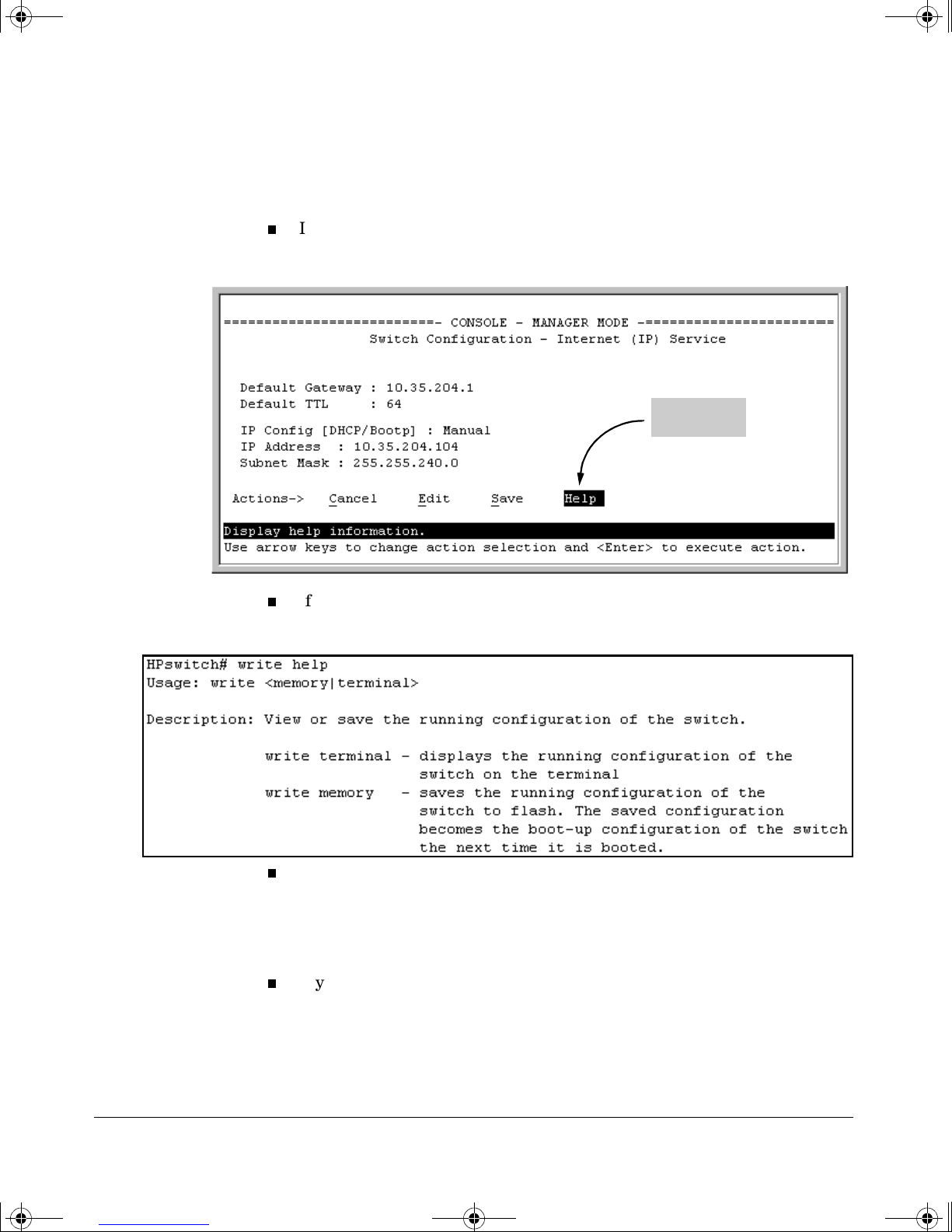
the switch’s console operates properly, use the write memory command
to save the switch’s running-config file to flash.
2-8
Page 35

!FishSecurity.book Page 9 Thursday, October 10, 2002 9:19 PM
Configuring TACACS+ on the Switch
Before You Begin
If you are new to TACACS+ authentication, HP recommends that you read the
“General Authentication Setup Procedure” on page 2-6 and configure your
TACACS+ server(s) before configuring authentication on the switch.
The switch offers three command areas for TACACS+ operation:
show authentication and show tacacs: Displays the switch’s TACACS+
configuration and status.
TACACS+ Authentication
Configuring TACACS+ on the Switch
aaa authentication: A command for configuring the switch’s authenti-
cation methods
tacacs-server: A command for configuring the switch’s contact with
TACACS+ servers
CLI Commands Described in this Section
Command Page
show authentication 2-10
show tacacs 2-10
aaa authentication pages 2-11 through 2-14
console
Telnet
num-attempts <1..10 >
tacacs-server pages 2-15
host < ip-addr > pages 2-15
key 2-19
timeout < 1 ..255 > 2-20
2-9
Page 36

!FishSecurity.book Page 10 Thursday, October 10, 2002 9:19 PM
TACACS+ Authentication
Configuring TACACS+ on the Switch
Viewing the Switch’s Current Authentication
Configuration
This command lists the number of login attempts the switch allows in a single
login session, and the primary/secondary access methods configured for each
type of access.
Syntax: show authentication
This example shows the default authentication configuration.
Configuration for login and enable access
to the switch through the switch console
port.
Figure 2-2. Example Listing of the Switch’s Authentication Configuration
Viewing the Switch’s Current TACACS+ Configuration
This command lists the timeout period, encryption key, and the IP addresses
of the first-choice and backup TACACS+ servers the switch can contact.
Syntax: show tacacs
For example, if the switch was configured for a first-choice and two backup
TACACS+ server addresses, the default timeout period, and paris-1 for a
(global) encryption key, show tacacs would produce a listing similar to the
following:
First-Choice
TACACS+ Server
Second-Choice
TACACS+ Server
Configuration for login and enable access
to the switch through Telnet.
Third-Choice
TACACS+ Server
Figure 2-3. Example of the Switch’s TACACS+ Configuration Listing
2-10
Page 37

!FishSecurity.book Page 11 Thursday, October 10, 2002 9:19 PM
Configuring the Switch’s Authentication Methods
The aaa authentication command configures the access control for console
port and Telnet access to the switch. That is, for both access methods, aaa
authentication specifies whether to use a TACACS+ server or the switch’s local
authentication, or (for some secondary scenarios) no authentication (meaning
that if the primary method fails, authentication is denied). This command also
reconfigures the number of access attempts to allow in a session if the first
attempt uses an incorrect username/password pair.
Syntax: aaa authentication
TACACS+ Authentication
Configuring TACACS+ on the Switch
< console | telnet >
Selects either console (serial port) or Telnet access for
configuration.
< enable | login >
Selects either the Manager (enable) or Operator (login)
access level.
< local | tacacs | radius >
Selects the type of security access:
local — Authenticates with the Manager and Operator
password you configure in the switch.
tacacs — Authenticates with a password and other
data configured on a TACACS+ server.
radius — Authenticates with a password and other
data configured on a RADIUS server. (Refer to
“RADIUS Authentication and Accounting” on page
3-1.)
[ < local | none > ]
If the primary authentication method fails, determines
whether to use the local password as a secondary method
or to disallow access.
aaa authentication num-attempts < 1. . 10 >
Specifies the maximum number of login attempts allowed in
the current session. Default: 3
2-11
Page 38

!FishSecurity.book Page 12 Thursday, October 10, 2002 9:19 PM
TACACS+ Authentication
Configuring TACACS+ on the Switch
Table 2-1. AAA Authentication Parameters
Name Default Range Function
console
- or -
telnet
enable
- or login
local
- or -
tacacs
local
- or -
none
num-attempts 3 1 - 10 In a given session, specifies how many tries at entering the correct username/
n/a n/a Specifies whether the command is configuring authentication for the console port
or Telnet access method for the switch.
n/a n/a Specifies the privilege level for the access method being configured.
login: Operator (read-only) privileges
enable: Manager (read-write) privileges
local n/a Specifies the primary method of authentication for the access method being
configured.
local: Use the username/password pair configured locally in the switch for
the privilege level being configured
tacacs: Use a TACACS+ server.
none n/a Specifies the secondary (backup) type of authentication being configured.
local: The username/password pair configured locally in the switch for the
privilege level being configured
none: No secondary type of authentication for the specified
method/privilege path. (Available only if the primary method of
authentication for the access being configured is local.)
Note: If you do not specify this parameter in the command line, the switch
automatically assigns the secondary method as follows:
• If the primary method is
• If the primary method is
password pair are allowed before access is denied and the session terminated.
tacacs, the only secondary method is local.
local, the default secondary method is none.
2-12
As shown in the next table, login and enable access is always available locally
through a direct terminal connection to the switch’s console port. However,
for Telnet access, you can configure TACACS+ to deny access if a TACACS+
server goes down or otherwise becomes unavailable to the switch.
Page 39

!FishSecurity.book Page 13 Thursday, October 10, 2002 9:19 PM
Table 2-2. Primary/Secondary Authentication Table
TACACS+ Authentication
Configuring TACACS+ on the Switch
Access Method and
Privilege Level
Console — Login local none* Local username/password access only.
Console — Enable local none* Local username/password access only.
Telne t — Login local none* Local username/password access only.
Telne t — Enable local none* Local username/password access only.
*When "local" is the primary optio n, you can also select "local" as t he secondary option. However, in this case, a secon dary
"local" is meaningless because the switch has only one local level of username/password protection.
Authentication Options Effect on Access Attempts
Primary Secondary
tacacs local If Tacacs+ server unavailable, uses local username/password access.
tacacs local If Tacacs+ server unavailable, uses local username/password access.
tacacs local If Tacacs+ server unavailable, uses local username/password access.
tacacs none If Tacacs+ server unavailable, denies access.
tacacs local If Tacacs+ server unavailable, uses local username/password access.
tacacs none If Tacacs+ server unavailable, denies access.
Caution Regarding
the Use of Local for
Login Primary
Access
During local authentication (which uses passwords configured in the switch
instead of in a TACACS+ server), the switch grants read-only access if you
enter the Operator password, and read-write access if you enter the Manager
password. For example, if you configure authentication on the switch with
Telnet Login Primary as Local and Telnet Enable Primary as Tacacs, when you
attempt to Telnet to the switch, you will be prompted for a local password. If
you enter the switch’s local Manager password (or, if there is no local Manager
password configured in the switch) you can bypass the TACACS+ server
authentication for Telnet Enable Primary and go directly to read-write (Manager) access. Thus, for either the Telnet or console access method, configuring
Login Primary for Local authentication while configuring Enable Primary for
TACACS+ authentication is not recommended, as it defeats the purpose of
using the TACACS+ authentication. If you want Enable Primary log-in
attempts to go to a TACACS+ server, then you should configure both Login
Primary and Enable Primary for Tacacs authentication instead of configuring
Login Primary to Local authentication.
2-13
Page 40

!FishSecurity.book Page 14 Thursday, October 10, 2002 9:19 PM
TACACS+ Authentication
Configuring TACACS+ on the Switch
For example, here is a set of access options and the corresponding
commands to configure them:
Console Login (Operator or Read-Only) Access: Primary using TACACS+ server.
Secondary using Local.
HPswitch (config)# aaa authentication console login tacacs local
Console Login (Operator or Read-Only
Access)
Primary Secondary
Console Enable (Manager or Read/Write Access: Primary using TACACS+ server.
Secondary using Local.
HPswitch (config)# aaa authentication console enable tacacs local
Console Login (Operator or Read-Only
Access)
Primary Secondary
Telnet Login (Operator or Read-Only) Access: Primary using TACACS+ server.
Secondary using Local.
HPswitch (config)# aaa authentication Telnet login tacacs local
Console Login (Operator or Read-Only
Access)
Primary Secondary
Telnet Enable (Manager or Read/Write Access: Primary using TACACS+ server.
Secondary using Local.
HPswitch (config)# aaa authentication telnet enable tacacs local
Deny Access and Close the Session After Failure of Two Consecutive Username/Password Pairs:
HPswitch(config)# aaa authentication num-attempts 2
2-14
Console Login (Operator or Read-Only
Access)
Primary Secondary
Attempt Limit
Page 41

!FishSecurity.book Page 15 Thursday, October 10, 2002 9:19 PM
Configuring the Switch’s TACACS+ Server Access
The tacacs-server command configures these parameters:
The host IP address(es) for up to three TACACS+ servers; one firstchoice and up to two backups. Designating backup servers provides
for a continuation of authentication services in case the switch is
unable to contact the first-choice server.
An optional encryption key. This key helps to improve security, and
must match the encryption key used in your TACACS+ server application. In some applications, the term "secret key" or "secret" may be
used instead of "encryption key". If you need only one encryption key
for the switch to use in all attempts to authenticate through a
TACACS+ server, configure a global key. However, if the switch is
configured to access multiple TACACS+ servers having different
encryption keys, you can configure the switch to use different encryption keys for different TACACS+ servers.
TACACS+ Authentication
Configuring TACACS+ on the Switch
The timeout value in seconds for attempts to contact a TACACS+
server. If the switch sends an authentication request, but does not
receive a response within the period specified by the timeout value,
the switch resends the request to the next server in its Server IP Addr
list, if any. If the switch still fails to receive a response from any
TACACS+ server, it reverts to whatever secondary authentication
method was configured using the aaa authentication command (local
or none; see “Configuring the Switch’s Authentication Methods” on
page 2-11.)
Note As described under “General Authentication Setup Procedure” on page 2-6,
HP recommends that you configure, test, and troubleshoot authentication via
Telnet access before you configure authentication via console port access.
This helps to prevent accidentally locking yourself out of switch access due
to errors or problems in setting up authentication in either the switch or your
TACACS+ server.
2-15
Page 42

!FishSecurity.book Page 16 Thursday, October 10, 2002 9:19 PM
TACACS+ Authentication
Configuring TACACS+ on the Switch
Note on
Encryption Keys
Syntax: tacacs-server host < ip-addr >
Adds a TACACS+ server and optionally assigns a server-specific
encryption key
[no] tacacs-server host < ip-addr >
Removes a TACACS+ server assignment (including its serverspecific encryption key, if any)
tacacs-server key <key-string>
Enters the optional global encryption key.
[no] tacacs-server key
Removes the optional global encryption key. (Does not affect any
server-specific encryption key assignments.)
tacacs-server timeout < 1 . . 255 >
Changes the wait period for a TACACS server response. (Default:
5 seconds.)
.
[key < key-string >]
.
Encryption keys configured in the switch must exactly match the encryption
keys configured in TACACS+ servers the switch will attempt to use for
authentication.
If you configure a global encryption key, the switch uses it only with servers
for which you have not also configured a server-specific key. Thus, a global
key is more useful where the TACACS+ servers you are using all have an
identical key, and server-specific keys are necessary where different
TACACS+ servers have different keys.
If TACACS+ server “X” does not have an encryption key assigned for the
switch, then configuring either a global encryption key or a server-specific key
in the switch for server “X” will block authentication support from server “X”.
2-16
Page 43

!FishSecurity.book Page 17 Thursday, October 10, 2002 9:19 PM
Name Default Range
host <ip-addr> [key <key-string> none n/a
Specifies the IP address of a device running a TACACS+ server application. Optionally, can also specify the unique, perserver encryption key to use when each assigned server has its own, unique key. For more on the encryption key, see
“Using the Encryption Key” on page 2-23 and the documentation provided with your TACACS+ server application.
You can enter up to three IP addresses; one first-choice and two (optional) backups (one second-choice and one thirdchoice).
Use show tacacs to view the current IP address list.
If the first-choice TACACS+ server fails to respond to a request, the switch tries the second address, if any, in the show
tacacs list. If the second address also fails, then the switch tries the third address, if any.
(See figure 2-3, "Example of the Switch’s TACACS+ Configuration Listing" on 2-10.)
The priority (first-choice, second-choice, and third-choice) of a TACACS+ server in the switch’s TACACS+ configuration
depends on the order in which you enter the server IP addresses:
1.When there are no TACACS+ servers configured, entering a server IP address makes that server the first-choice
TACACS+ server.
2.When there is one TACACS+ serves already configured, entering another server IP address makes that server the
second-choice (backup) TACACS+ server.
3.When there are two TACACS+ servers already configured, entering another server IP address makes that server
the third-choice (backup) TACACS+ server.
• The above position assignments are fixed. Thus, if you remove one server and replace it with another, the new server
assumes the priority position that the removed server had. For example, suppose you configured three servers, A, B,
and C, configured in order:
First-Choice: A
Second-Choice: B
Third-Choice: C
• If you removed server B and then entered server X, the TACACS+ server order of priority would be:
First-Choice: A
Second-Choice: X
Third-Choice: C
• If there are two or more vacant slots in the TACACS+ server priority list and you enter a new IP address, the new
address will take the vacant slot with the highest priority. Thus, if A, B, and C are configured as above and you (1)
remove A and B, and (2) enter X and Y (in that order), then the new TACACS+ server priority list would be X, Y, and C.
• The easiest way to change the order of the TACACS+ servers in the priority list is to remove all server addresses in
the list and then re-enter them in order, with the new first-choice server address first, and so on.
To add a new address to the list when there are already three addresses present, you must first remove one of the
currently listed addresses.
See also “General Authentication Process Using a TACACS+ Server” on page 2-20.
TACACS+ Authentication
Configuring TACACS+ on the Switch
2-17
Page 44

!FishSecurity.book Page 18 Thursday, October 10, 2002 9:19 PM
TACACS+ Authentication
Configuring TACACS+ on the Switch
Name Default Range
Name Default Range
key <key-string> none (null) n/a
Specifies the optional, global "encryption key" that is also assigned in the TACACS+ server(s) that the switch will access
for authentication. This option is subordinate to any "per-server" encryption keys you assign, and applies only to accessing
TACACS+ servers for which you have not given the switch a "per-server" key. (See the host <ip-addr> [key <key-string>
entry at the beginning of this table.)
For more on the encryption key, see “Using the Encryption Key” on page 2-23 and the documentation provided with your
TACACS+ server application.
timeout <1. . 255> 5 sec 1 - 255 sec
Specifies how long the switch waits for a TACACS+ server to respond to an authentication request. If the switch does
not detect a response within the timeout period, it initiates a new request to the next TACACS+ server in the list. If all
TACACS+ servers in the list fail to respond within the timeout period, the switch uses either local authentication (if
configured) or denies access (if none configured for local authentication).
Adding, Removing, or Changing the Priority of a TACACS+ Server.
Suppose that the switch was already configured to use TACACS+ servers at
10.28.227.10 and 10.28.227.15. In this case, 10.28.227.15 was entered first, and
so is listed as the first-choice server:
First-Choice TACACS+ Server
Figure 2-4. Example of the Switch with Two TACACS+ Server Addresses
Configured
To move the "first-choice" status from the "15" server to the "10" server, use
the
no tacacs-server host <ip-addr> command to delete both servers, then use
tacacs-server host <ip-addr> to re-enter the "10" server first, then the "15" server.
The servers would then be listed with the new "first-choice" server, that is:
2-18
Page 45

!FishSecurity.book Page 19 Thursday, October 10, 2002 9:19 PM
Figure 2-5. Example of the Switch After Assigning a Different "First-Choice" Server
To remove the 10.28.227.15 device as a TACACS+ server, you would use this
command:
TACACS+ Authentication
Configuring TACACS+ on the Switch
The "10" server is now the "first-choice" TACACS+ authentication device.
HPswitch(config)# no tacacs-server host 10.28.227.15
Configuring an Encryption Key. Use an encryption key in the switch if the
switch will be requesting authentication from a TACACS+ server that also uses
an encryption key. (If the server expects a key, but the switch either does not
provide one, or provides an incorrect key, then the authentication attempt will
fail.) Use a global encryption key if the same key applies to all TACACS+
servers the switch may use for authentication attempts. Use a per-server
encryption key if different servers the switch may use will have different keys.
(For more details on encryption keys, see “Using the Encryption Key” on page
2-23.)
To configure
north01 as a global encryption key:
HPswitch(config) tacacs-server key north01
To configure
north01 as a per-server encryption key:
HPswitch(config)tacacs-server host 10.28.227.63 key
north01
An encryption key can contain up to 100 characters, without spaces, and is
likely to be case-sensitive in most TACACS+ server applications.
To delete a global encryption key from the switch, use this command:
HPswitch(config)# no tacacs-server key
2-19
Page 46

!FishSecurity.book Page 20 Thursday, October 10, 2002 9:19 PM
TACACS+ Authentication
How Authentication Operates
To delete a per-server encryption key in the switch, re-enter the tacacs-server
host command without the key parameter. For example, if you have
configured as the encryption key for a TACACS+ server with an IP address of
10.28.227.104 and you want to eliminate the key, you would use this command:
HPswitch(config)# tacacs-server host 10.28.227.104
Note The show tacacs command lists the global encryption key, if configured.
However, to view any configured per-server encryption keys, you must use
show config or show config running (if you have made TACACS+ configuration
changes without executing
Configuring the Timeout Period. The timeout period specifies how long
the switch waits for a response to an authentication request from a TACACS+
server before either sending a new request to the next server in the switch’s
Server IP Address list or using the local authentication option. For example,
to change the timeout period from 5 seconds (the default) to 3 seconds:
north01
write mem).
First-Choice
TACACS+ Server
Second-Choice
TACACS+ Server
(Optional)
Third-Choice
TACACS+ Server
(Optional)
HPswitch(config)# tacacs-server timeout 3
How Authentication Operates
General Authentication Process Using a TACACS+
Server
Authentication through a TACACS+ server operates generally as described
below. For specific operating details, refer to the documentation you received
with your TACACS+ server application.
Terminal "A" Directly Accessing This
Switch Via Switch’s Console Port
HP Switch
Configured for
TACACS+ Operation
HP Switch Configured
for TACACS+ Operation
A
Terminal "B" Remotely Accessing
This Switch Via Telnet
B
Figure 2-6. Using a TACACS+ Server for Authentication
2-20
Page 47

!FishSecurity.book Page 21 Thursday, October 10, 2002 9:19 PM
Using figure 2-6, above, after either switch detects an operator’s logon request
from a remote or directly connected terminal, the following events occur:
1. The switch queries the first-choice TACACS+ server for authentication
of the request.
• If the switch does not receive a response from the first-choice
TACACS+ server, it attempts to query a secondary server. If the
switch does not receive a response from any TACACS+ server,
then it uses its own local username/password pairs to authenticate the logon request. (See “Local Authentication Process” on
page 2-22.)
• If a TACACS+ server recognizes the switch, it forwards a user-
name prompt to the requesting terminal via the switch.
2. When the requesting terminal responds to the prompt with a username,
the switch forwards it to the TACACS+ server.
TACACS+ Authentication
How Authentication Operates
3. After the server receives the username input, the requesting terminal
receives a password prompt from the server via the switch.
4. When the requesting terminal responds to the prompt with a password,
the switch forwards it to the TACACS+ server and one of the following
actions occurs:
• If the username/password pair received from the requesting
terminal matches a username/password pair previously stored in
the server, then the server passes access permission through the
switch to the terminal.
• If the username/password pair entered at the requesting terminal
does not match a username/password pair previously stored in
the server, access is denied. In this case, the terminal is again
prompted to enter a username and repeat steps 2 through 4. In
the default configuration, the switch allows up to three attempts
to authenticate a login session. If the requesting terminal
exhausts the attempt limit without a successful TACACS+
authentication, the login session is terminated and the operator
at the requesting terminal must initiate a new session before
trying again.
2-21
Page 48

!FishSecurity.book Page 22 Thursday, October 10, 2002 9:19 PM
TACACS+ Authentication
How Authentication Operates
Local Authentication Process
When the switch is configured to use TACACS+, it reverts to local authentication only if one of these two conditions exists:
"Local" is the authentication option for the access method being used.
TACACS+ is the primary authentication mode for the access method
being used. However, the switch was unable to connect to any
TACACS+ servers (or no servers were configured) AND Local is the
secondary authentication mode being used.
(For a listing of authentication options, see table 2-2, “Primary/Secondary
Authentication Table” on 2-13.)
For local authentication, the switch uses the operator-level and manager-level
username/password set(s) previously configured locally on the switch. (These
are the usernames and passwords you can configure using the CLI password
command, the web browser interface, or the menu interface—which enables
only local password configuration).
If the operator at the requesting terminal correctly enters the username/password pair for either access level, access is granted.
If the username/password pair entered at the requesting terminal does
not match either username/password pair previously configured
locally in the switch, access is denied. In this case, the terminal is
again prompted to enter a username/password pair. In the default
configuration, the switch allows up to three attempts. If the requesting
terminal exhausts the attempt limit without a successful authentication, the login session is terminated and the operator at the requesting
terminal must initiate a new session before trying again.
Note The switch’s menu allows you to configure only the local Operator and
Manager passwords, and not any usernames. In this case, all prompts for local
authentication will request only a local password. However, if you use the CLI
or the web browser interface to configure usernames for local access, you will
see a prompt for both a local username and a local password during local
authentication.
2-22
Page 49

!FishSecurity.book Page 23 Thursday, October 10, 2002 9:19 PM
Using the Encryption Key
General Operation
When used, the encryption key (sometimes termed "key", "secret key", or
"secret") helps to prevent unauthorized intruders on the network from reading
username and password information in TACACS+ packets moving between
the switch and a TACACS+ server. At the TACACS+ server, a key may include
both of the following:
Global key: A general key assignment in the TACACS+ server application that applies to all TACACS-aware devices for which an individual key has not been configured.
Server-Specific key: A unique key assignment in the TACACS+
server application that applies to a specific TACACS-aware device.
TACACS+ Authentication
How Authentication Operates
Note Configure a key in the switch only if the TACACS+ server application has this
exact same key configured for the switch. That is, if the key parameter in
switch "X" does not exactly match the key setting for switch "X" in the
TACACS+ server application, then communication between the switch and
the TACACS+ server will fail.
Thus, on the TACACS+ server side, you have a choice as to how to implement
a key. On the switch side, it is necessary only to enter the key parameter so
that it exactly matches its counterpart in the server. For information on how
to configure a general or individual key in the TACACS+ server, refer to the
documentation you received with the application.
Encryption Options in the Switch
When configured, the encryption key causes the switch to encrypt the
TACACS+ packets it sends to the server. When left at "null", the TACACS+
packets are sent in clear text. The encryption key (or just "key") you configure
in the switch must be identical to the encryption key configured in the
corresponding TACACS+ server. If the key is the same for all TACACS+
servers the switch will use for authentication, then configure a global key in
the switch. If the key is different for one or more of these servers, use "serverspecific" keys in the switch. (If you configure both a global key and one or
more per-server keys, the per-server keys will override the global key for the
specified servers.)
2-23
Page 50

!FishSecurity.book Page 24 Thursday, October 10, 2002 9:19 PM
TACACS+ Authentication
Controlling Web Browser Interface Access When Using TACACS+ Authentication
For example, you would use the next command to configure a global encryption key in the switch to match a key entered as
TACACS+ servers. (That is, both servers use the same key for your switch.)
Note that you do not need the server IP addresses to configure a global key in
the switch:
HPswitch(config)# tacacs-server key north40campus
Suppose that you subsequently add a third TACACS+ server (with an IP
address of 10.28.227.87) that has
this key is different than the one used for the two servers in the previous
example, you will need to assign a server-specific key in the switch that applies
only to the designated server:
HPswitch(config)# tacacs-server host 10.28.227.87 key
south10campus
north40campus in two target
south10campus for an encryption key. Because
With both of the above keys configured in the switch, the
overrides the
TACACS+ server having the 10.28.227.87 address.
north40campus key only when the switch tries to access the
south10campus key
Controlling Web Browser Interface
Access When Using TACACS+
Authentication
Configuring the switch for TACACS+ authentication does not affect web
browser interface access. To prevent unauthorized access through the web
browser interface, do one or more of the following:
Configure local authentication (a Manager user name and password
and, optionally, an Operator user name and password) on the switch.
Configure the switch’s Authorized IP Manager feature to allow web
browser access only from authorized management stations. (The
Authorized IP Manager feature does not interfere with TACACS+
operation.)
Disable web browser access to the switch by going to the System
Information screen in the Menu interface and configuring the
Agent Enabled
2-24
Web
parameter to No.
Page 51

!FishSecurity.book Page 25 Thursday, October 10, 2002 9:19 PM
Messages Related to TACACS+
Operation
The switch generates the CLI messages listed below. However, you may see
other messages generated in your TACACS+ server application. For information on such messages, refer to the documentation you received with the
application.
CLI Message Meaning
Connecting to Tacacs server The switch is attempting to contact the TACACS+ server identified in the switch’s tacacs-
server
configuration as the first-choice (or only) TACACS+ server.
TACACS+ Authentication
Messages Related to TACACS+ Operation
Connecting to secondary
Tacacs server
The switch was not able to contact the first-choice TACACS+ server, and is now
attempting to contact the next (secondary) TACACS+ server identified in the switch’s
tacacs-server configuration.
Invalid password The system does not recognize the username or the password or both. Depending on the
authentication method (tacacs or local), either the TACACS+ server application did not
recognize the username/password pair or the username/password pair did not match the
username/password pair configured in the switch.
No Tacacs servers
responding
Not legal combination of
authentication methods
Record already exists When resulting from a tacacs-server host <ip addr> command, indicates an attempt to
The switch has not been able to contact an y designated TAC ACS+ servers. If this message
is followed by the Username prompt, the switch is attempting local authentication.
For console access, if you select tacacs as the primary authentication method, you must
select local as the secondar y authentication method. T his prevents you from being locked
out of the switch if all designated TACACS+ servers are inaccessible to the switch.
enter a duplicate TACACS+ server IP address.
Operating Notes
If you configure Authorized IP Managers on the switch, it is not
necessary to include any devices used as TACACS+ servers in the
authorized manager list. That is, authentication traffic between a
TACACS+ server and the switch is not subject to Authorized IP
Manager controls configured on the switch. Also, the switch does not
attempt TACACS+ authentication for a management station that the
Authorized IP Manager list excludes because, independent of
TACACS+, the switch already denies access to such stations.
2-25
Page 52

!FishSecurity.book Page 26 Thursday, October 10, 2002 9:19 PM
TACACS+ Authentication
Operating Notes
When TACACS+ is not enabled on the switch—or when the switch’s
only designated TACACS+ servers are not accessible— setting a local
Operator password without also setting a local Manager password
does not protect the switch from manager-level access by unauthorized persons.)
2-26
Page 53

!FishSecurity.book Page 1 Thursday, October 10, 2002 9:19 PM
RADIUS Authentication and Accounting
Contents
Overview . . . . . . . . . . . . . . . . . . . . . . . . . . . . . . . . . . . . . . . . . . . . . . . . . . . . . 3-2
Terminology . . . . . . . . . . . . . . . . . . . . . . . . . . . . . . . . . . . . . . . . . . . . . . . . . . 3-3
Switch Operating Rules for RADIUS . . . . . . . . . . . . . . . . . . . . . . . . . . . . 3-4
General RADIUS Setup Procedure . . . . . . . . . . . . . . . . . . . . . . . . . . . . . 3-5
3
Configuring the Switch for RADIUS Authentication . . . . . . . . . . . . . 3-6
Outline of the Steps for Configuring RADIUS Authentication . . . . . . 3-6
1. Configure Authentication for the Access Methods You Want
RADIUS To Protect . . . . . . . . . . . . . . . . . . . . . . . . . . . . . . . . . . . . . . . . 3-8
2. Configure the Switch To Access a RADIUS Server . . . . . . . . . . . . 3-10
3. Configure the Switch’s Global RADIUS Parameters . . . . . . . . . . . 3-12
Local Authentication Process . . . . . . . . . . . . . . . . . . . . . . . . . . . . . . . . . 3-14
Controlling Web Browser Interface Access When Using RADIUS
Authentication . . . . . . . . . . . . . . . . . . . . . . . . . . . . . . . . . . . . . . . . . . . . . . . 3-15
Configuring RADIUS Accounting . . . . . . . . . . . . . . . . . . . . . . . . . . . . . . 3-16
Operating Rules for RADIUS Accounting . . . . . . . . . . . . . . . . . . . . . . 3-17
Steps for Configuring RADIUS Accounting . . . . . . . . . . . . . . . . . . . . . 3-18
1. Configure the Switch To Access a RADIUS Server . . . . . . . . . 3-19
2. Configure Accounting Types and the Controls for Sending
Reports to the RADIUS Server . . . . . . . . . . . . . . . . . . . . . . . . . . 3-20
3. (Optional) Configure Session Blocking and Interim
Updating Options . . . . . . . . . . . . . . . . . . . . . . . . . . . . . . . . . . . . . 3-22
Viewing RADIUS Statistics . . . . . . . . . . . . . . . . . . . . . . . . . . . . . . . . . . . . 3-23
General RADIUS Statistics . . . . . . . . . . . . . . . . . . . . . . . . . . . . . . . . . . . 3-23
RADIUS Authentication Statistics . . . . . . . . . . . . . . . . . . . . . . . . . . . . . 3-25
RADIUS Accounting Statistics . . . . . . . . . . . . . . . . . . . . . . . . . . . . . . . . 3-26
Changing RADIUS-Server Access Order . . . . . . . . . . . . . . . . . . . . . . . 3-27
Messages Related to RADIUS Operation . . . . . . . . . . . . . . . . . . . . . . . 3-29
3-1
Page 54

!FishSecurity.book Page 2 Thursday, October 10, 2002 9:19 PM
RADIUS Authentication and Accounting
Overview
Overview
Feature Default Menu CLI Web
Configuring RADIUS Authentication None n/a 3-6 n/a
Configuring RADIUS Accounting None n/a 3-16 n/a
Viewing RADIUS Statistics n/a n/a 3-23 n/a
RADIUS (Remote Authentication Dial-In User Service) enables you to use
up to three servers (one primary server and one or two backups) and maintain
separate authentication and accounting for each RADIUS server employed.
For authentication, this allows a different password for each user instead of
having to rely on maintaining and distributing switch-specific passwords to
all users. For accounting, this can help you track network resource usage.
Authentication. You can use RADIUS to verify user identity for the following types of primary password access to the HP switch:
Serial port (Console)
Telnet
SSH
Port-Access
Note The switch does not support RADIUS security for SNMP (network manage-
ment) access or web browser interface access. For steps to block unauthorized access through the web browser interface, see “Controlling Web
Browser Interface Access When Using RADIUS Authentication” on page 3-15.
Accounting. RADIUS accounting on the switch collects resource consumption data and forwards it to the RADIUS server. This data can be used for trend
analysis, capacity planning, billing, auditing, and cost analysis.
3-2
Page 55

!FishSecurity.book Page 3 Thursday, October 10, 2002 9:19 PM
Terminology
CHAP (Challenge-Handshake Authentication Protocol): A challengeresponse authentication protocol that uses the Message Digest 5 (MD5)
hashing scheme to encrypt a response to a challenge from a RADIUS server.
EAP(Extensible Authentication Protocol): A general PPP authentication
protocol that supports multiple authentication mechanisms. A specific
authentication mechanism is known as an EAP type, such as MD5-Challenge,
Generic Token Card, and TLS (Transport Level Security).
Host: See RADIUS Server.
RADIUS Authentication and Accounting
Terminology
NAS (Network Access Server): In this case, an HP switch configured for
RADIUS security operation.
RADIUS (Remote Authentication Dial In User Service):
RADIUS Client: The device that passes user information to designated
RADIUS servers.
RADIUS Host: See RADIUS server.
RADIUS Server: A server running the RADIUS application you are using on
your network. This server receives user connection requests from the switch,
authenticates users, and then returns all necessary information to the switch.
For the HP switch, a RADIUS server can also perform accounting functions.
Sometimes termed a RADIUS host.
Shared Secret Key: A text value used for encrypting data in RADIUS packets.
Both the RADIUS client and the RADIUS server have a copy of the key, and
the key is never transmitted across the network.
3-3
Page 56

!FishSecurity.book Page 4 Thursday, October 10, 2002 9:19 PM
RADIUS Authentication and Accounting
Switch Operating Rules for RADIUS
Switch Operating Rules for RADIUS
You must have at least one RADIUS server accessible to the switch.
The switch supports authentication and accounting using up to three
RADIUS servers. The switch accesses the servers in the order in
which they are listed by show radius ( page 3-23). If the first server
does not respond, the switch tries the next one, and so-on. (To change
the order in which the switch accesses RADIUS servers, refer to
“Changing RADIUS-Server Access Order” on page 3-27.)
You can select RADIUS as the primary authentication method for each
type of access. (Only one primary and one secondary access method
is allowed for each access type.)
In the HP switch, EAP RADIUS uses MD5 and TLS to encrypt a
response to a challenge from a RADIUS server.
3-4
Page 57

!FishSecurity.book Page 5 Thursday, October 10, 2002 9:19 PM
General RADIUS Setup Procedure
Preparation:
1. Configure one to three RADIUS servers to support the switch. (That is,
one primary server and one or two backups.) Refer to the documentation
provided with the RADIUS server application.
2. Before configuring the switch, collect the information outlined below.
Table 3-1. Preparation for Configuring RADIUS on the Switch
• Determine the access methods (console, Telnet, Port-Access, and/or SSH) for which you want RADIUS as the primary
authentication method. Consider both Operator (login) and Manager (enable) levels, as well as which secondary
authentication methods to use (local or none) if the RADIUS authentication fails or does not respond.
RADIUS Authentication and Accounting
General RADIUS Setup Procedure
Console access
requires Local as
secondary method to
prevent lockout if the
primary RADIUS
access fails due to loss
of RADIUS server
access or other
problems with the
server.
Figure 3-1. Example of Possible RADIUS Access Assignments
• Determine the IP address(es) of the RADIUS server(s) you want to support the switch. (You can configure the switch
for up to three RADIUS servers.)
• If you need to replace the default UDP destination port (1812) the switch uses for authentication requests to a specific
RADIUS server, select it before beginning the configuration process.
• If you need to replace the default UDP destination port (1813) the switch uses for accounting requests to a specific
Radius server, select it before beginning the configuration process.
• Determine whether you can use one, global encryption key for all RADIUS servers or if unique keys will be required
for specific servers. With multiple RADIUS servers, if one key applies to two or more of these servers, then you can
configure this key as the global encryption key. For any server whose key differs from the global key you are using,
you must configure that key in the same command that you use to designate that server’s IP address to the switch.
• Determine an acceptable timeout period for the switch to wait for a server to respond to a request. HP recommends
that you begin with the default (five seconds).
• Determine how many times you want the switch to try contacting a RADIUS server before trying another RADIUS
server or quitting. (This depends on how many RADIUS servers you have configured the switch to access.)
• Determine whether you want to bypass a RADIUS server that fails to respond to requests for service. To shorten
authentication time, you can set a bypass period in the range of 1 to 1440 minutes for non-responsive servers. This
requires that you have multiple RADIUS servers accessible for service requests.
3-5
Page 58

!FishSecurity.book Page 6 Thursday, October 10, 2002 9:19 PM
RADIUS Authentication and Accounting
Configuring the Switch for RADIUS Authentication
Configuring the Switch for RADIUS
Authentication
RADIUS Authentication Commands Page
aaa authentication 3-8
< console | telnet | ssh > < enable | login > radius 3-8
< local | none > 3-8
[no] radius-server host < IP-address >3-10
[auth-port < port-number >] 3-10
[acct-port < port-number >] 3-10, 3-19
[key < server-specific key-string >] 3-10
[no] radius-server key < global key-string >3-12
radius-server timeout < 1 .. 15> 3-12
radius-server retransmit < 1 .. 5 > 3-12
[no] radius-server dead-time < 1 .. 1440 > 3-13
show radius 3-23
[< host < ip-address>] 3-23
show authentication 3-25
show radius authentication 3-25
3-6
Outline of the Steps for Configuring RADIUS
Authentication
There are three main steps to configuring RADIUS authentication:
1. Configure RADIUS authentication for controlling access through one or
more of the following
• Serial port
• Teln et
• SSH
• Port-Access (802.1x)
2. Configure the switch for accessing one or more RADIUS servers (one
primary server and up to two backup servers):
Page 59

!FishSecurity.book Page 7 Thursday, October 10, 2002 9:19 PM
Note This step assumes you have already configured the RADIUS server(s) to
support the switch. Refer to the documentation provided with the
RADIUS server documentation.)
• Server IP address
• (Optional) UDP destination port for authentication requests (default:
1812; recommended)
• (Optional) UDP destination port for accounting requests (default:
1813; recommended)
• (Optional) encryption key for use during authentication sessions with
a RADIUS server. This key overrides the global encryption key you
can also configure on the switch, and must match the encryption key
used on the specified RADIUS server. (Default: null)
3. Configure the global RADIUS parameters.
• Server Key: This key must match the encryption key used on the
RADIUS servers the switch contacts for authentication and accounting services unless you configure one or more per-server keys.
(Default: null.)
• Time o ut P e ri o d: The timeout period the switch waits for a RADIUS
server to reply. (Default: 5 seconds; range: 1 to 15 seconds.)
• Retransmit Attempts: The number of retries when there is no server
response to a RADIUS authentication request. (Default: 3; range of 1
to 5.)
• Server Dead-Time: The period during which the switch will not send
new authentication requests to a RADIUS server that has failed to
respond to a previous request. This avoids a wait for a request to time
out on a server that is unavailable. If you want to use this feature,
select a dead-time period of 1 to 1440 minutes. (Default: 0—disabled;
range: 1 - 1440 minutes.) If your first-choice server was initially
unavailable, but then becomes available before the dead-time expires,
you can nullify the dead-time by resetting it to zero and then trying to
log on again. As an alternative, you can reboot the switch, (thus
resetting the dead-time counter to assume the server is available) and
then try to log on again.
• Number of Login Attempts: This is actually an aaa authentication
command. It controls how many times in one session a RADIUS client
(as well as clients using other forms of access) can try to log in with
the correct username and password. (Default: Three times per session.)
RADIUS Authentication and Accounting
Configuring the Switch for RADIUS Authentication
(For RADIUS accounting features, refer to “Configuring RADIUS Accounting”
on page 3-16.)
3-7
Page 60

!FishSecurity.book Page 8 Thursday, October 10, 2002 9:19 PM
RADIUS Authentication and Accounting
Configuring the Switch for RADIUS Authentication
1. Configure Authentication for the Access Methods You
Want RADIUS To Protect
This section describes how to configure the switch for RADIUS authentication
through the following access methods:
Console: Either direct serial-port connection or modem connection.
Tel n et : Inbound Telnet must be enabled (the default).
SSH: To employ RADIUS for SSH access, you must first configure the
switch for SSH operation. Refer to “Configuring Secure Shell (SSH)”
on page 4-1.
You can also use RADIUS for Port-Based Access authentication. Refer to
“Configuring Port-Based Access Control (802.1x)” on page 5-1.
You can configure RADIUS as the primary password authentication method
for the above access methods. You will also need to select either local or none
as a secondary, or backup, method. Note that for console access, if you
configure radius (or tacacs) for primary authentication, you must configure
local for the secondary method. This prevents the possibility of being completely locked out of the switch in the event that all primary access methods
fail.
Syntax: aaa authentication < console | telnet | ssh > < enable | login > < radius >
Configures RADIUS as the primary password authentication
method for console, Telnet, and/or SSH. (The default primary
< enable | login > authentication is local.)
[< local | none >]
Provides options for secondary authentication
(default: none). Note that for console access, secondary
authentication must be local if primary access is not
local. This prevents you from being completely locked
out of the switch in the event of a failure in other access
methods.
3-8
Page 61

!FishSecurity.book Page 9 Thursday, October 10, 2002 9:19 PM
For example, suppose you have already configured local passwords on the
switch, but want to use RADIUS to protect primary Telnet and SSH access
without allowing a secondary Telnet or SSH access option (which would be
the switch’s local passwords):
RADIUS Authentication and Accounting
Configuring the Switch for RADIUS Authentication
The switch now
allows Telnet and
SSH authentication
only through
Figure 3-2. Example Configuration for RADIUS Authentication
Note In the above example, if you configure the Login Primary method as local
instead of radius (and local passwords are configured on the switch), then you
can gain access to either the Operator or Manager level without encountering
the RADIUS authentication specified for Enable Primary. Refer to “Local
Authentication Process” on page 3-14.
3-9
Page 62

!FishSecurity.book Page 10 Thursday, October 10, 2002 9:19 PM
RADIUS Authentication and Accounting
Configuring the Switch for RADIUS Authentication
2. Configure the Switch To Access a RADIUS Server
This section describes how to configure the switch to interact with a RADIUS
server for both authentication and accounting services.
Note If you want to configure RADIUS accounting on the switch, go to page 3-16:
“Configuring RADIUS Accounting” instead of continuing here.
Syntax: [no] radius-server host < ip-address >
Adds a server to the RADIUS configuration or (with no)
deletes a server from the configuration. You can configure
up to three RADIUS server addresses. The switch uses the
first server it successfully accesses. (Refer to "Changing
the RADIUS Server Access Order" on page 3-27.)
[auth-port < port-number >]
Optional. Changes the UDP destination port for authentication requests to the specified RADIUS server (host). If
you do not use this option with the radius-server host
command, the switch automatically assigns the default
authentication port number. The auth-port number must
match its server counterpart. (Default: 1812)
[acct-port < port-number >]
Optional. Changes the UDP destination port for accounting requests to the specified RADIUS server. If you do not
use this option with the radius-server host command, the
switch automatically assigns the default accounting port
number. The acct-port number must match its server counterpart.(Default: 1813)
[key < key-string >]
Optional. Specifies an encryption key for use during
authentication (or accounting) sessions with the specified
server. This key must match the encryption key used on
the RADIUS server. Use this command only if the specified
server requires a different encryption key than configured
for the global encryption key.
3-10
no radius-server host < ip-address > key
Use the no form of the command to remove the key for a
specified server.
Page 63

!FishSecurity.book Page 11 Thursday, October 10, 2002 9:19 PM
For example, suppose you have configured the switch as shown in figure 3-3
and you now need to make the following changes:
1. Change the encryption key for the server at 10.33.18.127 to "source0127".
2. Add a RADIUS server with an IP address of 10.33.18.119 and a serverspecific encryption key of "source0119".
RADIUS Authentication and Accounting
Configuring the Switch for RADIUS Authentication
Figure 3-3. Sample Configuration for RADIUS Server Before Changing the Key and
Adding Another Server
To make the changes listed prior to figure 3-3, you would do the following:
Changes the key
for the existing
server to
"source0127" (step
Adds the new
RADIUS server
with its required
"source0119" key.
Lists the switch’s
new RADIUS
server
configuration.
Compare this with
Figure 3-4. Sample Configuration for RADIUS Server After Changing the Key and Adding Another Server
To change the order in which the switch accesses RADIUS servers, refer to
“Changing RADIUS-Server Access Order” on page 3-27.
3-11
Page 64

!FishSecurity.book Page 12 Thursday, October 10, 2002 9:19 PM
RADIUS Authentication and Accounting
Configuring the Switch for RADIUS Authentication
3. Configure the Switch’s Global RADIUS Parameters
You can configure the switch for the following global RADIUS parameters:
Number of login attempts: In a given session, specifies how many
tries at entering the correct username and password pair are allowed
before access is denied and the session terminated. (This is a general
aaa authentication parameter and is not specific to RADIUS.)
Global server key: The server key the switch will use for contacts
with all RADIUS servers for which there is not a server-specific key
configured by radius-server host < ip-address > key < key-string >.
This key is optional if you configure a server-specific key for each
RADIUS server entered in the switch. (Refer to “2. Configure the
Switch To Access a RADIUS Server” on page 3-10.)
Server timeout: Defines the time period in seconds for authentication attempts. If the timeout period expires before a response is
received, the attempt fails.
Server dead time: Specifes the time in minutes during which the
switch avoids requesting authentication from a server that has not
responded to previous requests.
Retransmit attempts: If the first attempt to contact a RADIUS
server fails, specifies how many retries you want the switch to attempt
on that server.
Syntax: aaa authentication num-attempts <1 .. 10 >
Specifies how many tries for entering the correct username
and password before shutting down the session due to input
errors. (Default: 3; Range: 1 - 10).
[no] radius-server
key < global-key-string >
Specifies the global encryption key the switch uses with
servers for which the switch does not have a serverspecific key assignment. This key is optional if all
RADIUS server addresses configured in the switch include a server-specific encryption key. (Default: Null.)
3-12
dead-time < 1 .. 1440 >
Optional. Specifies the time in minutes during which
the switch will not attempt to use a RADIUS server that
has not responded to an earlier authentication attempt.
(Default: 0; Range: 1 - 1440 minutes)
Page 65

!FishSecurity.book Page 13 Thursday, October 10, 2002 9:19 PM
radius-server timeout < 1 .. 15 >
radius-server retransmit < 1 .. 5 >
Note Where the switch has multiple RADIUS servers configured to support authen-
tication requests, if the first server fails to respond, then the switch tries the
next server in the list, and so-on. If none of the servers respond, then the switch
attempts to use the secondary authentication method configured for the type
of access being attempted (console, Telnet, or SSH). If this occurs, refer to
"RADIUS-Related Problems" in the Troubleshooting chapter of the Manage-
ment and Configuration Guide for your switch.
RADIUS Authentication and Accounting
Configuring the Switch for RADIUS Authentication
Specifies the maximum time the switch waits for a response
to an authentication request before counting the attempt as
a failure. (Default: 3 seconds; Range: 1 - 15 seconds)
If a RADIUS server fails to respond to an authentication
request, specifies how many retries to attempt before closing
the session. Default: 3; Range: 1 - 5)
For example, suppose that your switch is configured to use three RADIUS
servers for authenticating access through Telnet and SSH. Two of these servers
use the same encryption key. In this case your plan is to configure the switch
with the following global authentication parameters:
Allow only two tries to correctly enter username and password.
Use the global encryption key to support the two servers that use the
same key. (For this example, assume that you did not configure these
two servers with a server-specific key.)
Use a dead-time of five minutes for a server that fails to respond to
an authentication request.
Allow three seconds for request timeouts.
Allow two retries following a request that did not receive a response.
Figure 3-5. Example of Global Configuration Exercise for RADIUS Authentication
3-13
Page 66

!FishSecurity.book Page 14 Thursday, October 10, 2002 9:19 PM
RADIUS Authentication and Accounting
Local Authentication Process
After two attempts failing due
to username or password
entry errors, the switch will
terminate the session.
Global RADIUS parameters
from figure 3-5.
Figure 3-6. Listings of Global RADIUS Parameters Configured In Figure 3-5
Local Authentication Process
When the switch is configured to use RADIUS, it reverts to local authentication
only if one of these two conditions exists:
"Local" is the authentication option for the access method being used.
The switch has been configured to query one or more RADIUS servers
for a primary authentication request, but has not received a response,
and local is the configured secondary option.
Server-specific encryption key
for the RADIUS server that will
not use the global encryption
key.
These two servers will use the
global encryption key.
3-14
Page 67

!FishSecurity.book Page 15 Thursday, October 10, 2002 9:19 PM
Controlling Web Browser Interface Access When Using RADIUS Authentication
For local authentication, the switch uses the Operator-level and Manager-level
username/password set(s) previously configured locally on the switch. (These
are the usernames and passwords you can configure using the CLI password
command, the web browser interface, or the menu interface—which enables
only local password configuration).
If the operator at the requesting terminal correctly enters the username/password pair for either access level (Operator or Manager),
access is granted on the basis of which username/password pair was
used. For example, suppose you configure Telnet primary access for
RADIUS and Telnet secondary access for local. If a RADIUS access
attempt fails, then you can still get access to either the Operator or
Manager level of the switch by entering the correct username/password pair for the level you want to enter.
If the username/password pair entered at the requesting terminal does
not match either local username/password pair previously configured
in the switch, access is denied. In this case, the terminal is again
prompted to enter a username/password pair. In the default configuration, the switch allows up to three attempts. If the requesting
terminal exhausts the attempt limit without a successful authentication, the login session is terminated and the operator at the requesting
terminal must initiate a new session before trying again.
RADIUS Authentication and Accounting
Controlling Web Browser Interface
Access When Using RADIUS
Authentication
Configuring the switch for RADIUS authentication does not affect web
browser interface access. To prevent unauthorized access through the web
browser interface, do one or more of the following:
Configure local authentication (a Manager user name and password
and, optionally, an Operator user name and password) on the switch.
Configure the switch’s Authorized IP Manager feature to allow web
browser access only from authorized management stations. (The
Authorized IP Manager feature does not interfere with TACACS+
operation.)
Disable web browser access to the switch.
3-15
Page 68

!FishSecurity.book Page 16 Thursday, October 10, 2002 9:19 PM
RADIUS Authentication and Accounting
Configuring RADIUS Accounting
Configuring RADIUS Accounting
RADIUS Accounting Commands Page
[no] radius-server host < ip-address >3-19
[ acct-port < port-number >] 3-19
[key < key-string >] 3-19
[no] aaa accounting < exec | network | system >
< start-stop | stop-only> radius
[no] aaa accounting update
periodic < 1 .. 525600 > (in minutes)
[no] aaa accounting suppress null-username 3-22
show accounting 3-26
show accounting sessions 3-27
show radius accounting 3-26
3-21
3-22
Note This section assumes you have already:
Configured RADIUS authentication on the switch for one or more
access methods
Configured one or more RADIUS servers to support the switch
If you have not already done so, refer to “General RADIUS Setup Procedure”
on page 3-5 before continuing here.
RADIUS accounting collects data about user activity and system events and
sends it to a RADIUS server when specified events occur on the switch, such
as a logoff or a reboot. The Switch 2650 and 6108 support three types of
accounting services:
Network accounting: Provides records containing the information
listed below on clients directly connected to the switch and operating
under Port-Based Access Control (802.1x):
• Acct-Session-Id
• Acct-Status-Type
• Acct-Terminate-Cause
• Acct-Authentic
• Acct-Delay-Time
• Acct-Input-Packets
• Acct-Output-Packets
• Acct-Input-Octets
• Nas-Port
• Acct-Output-Octets
• Acct-Session-Time
• Username
• Service-Type
• NAS-IP-Address
• NAS-Identifier
• Called-Station-Id
3-16
Page 69

!FishSecurity.book Page 17 Thursday, October 10, 2002 9:19 PM
(For 802.1x information for the switch, refer to “Configuring Port-Based
Access Control (802.1x)” on page 5-1.)
Exec accounting: Provides records containing the information
listed below about login sessions (console, Telnet, and SSH) on the
switch:
RADIUS Authentication and Accounting
Configuring RADIUS Accounting
• Acct-Session-Id
• Acct-Status-Type
• Acct-Terminate-Cause
• Acct-Authentic
System accounting: Provides records containing the information
• Acct-Delay-Time
• Acct-Session-Time
• Username
• Service-Type
• NAS-IP-Address
• NAS-Identifier
• Calling-Station-Id
listed below when system events occur on the switch, including
system reset, system boot, and enabling or disabling of system
accounting.
• Acct-Session-Id
• Acct-Status-Type
• Acct-Terminate-Cause
• Acct-Authentic
• Acct-Delay-Time
• Username
• Service-Type
• NAS-IP-Address
• NAS-Identifier
• Calling-Station-Id
The switch forwards the accounting information it collects to the designated
RADIUS server, where the information is formatted, stored, and managed by
the server. For more information on this aspect of RADIUS accounting, refer
to the documentation provided with your RADIUS server.
Operating Rules for RADIUS Accounting
You can configure up to three types of accounting to run simultaneously: exec, system, and network.
RADIUS servers used for accounting are also used for authentication.
The switch must be cofigured to access at least one RADIUS server.
RADIUS servers are accessed in the order in which their IP addresses
were configured in the switch. Use show radius to view the order.
As long as the first server is accesssible and responding to authentication requests from the switch, a second or third server will not be
accessed. (For more on this topic, refer to “Changing RADIUS-Server
Access Order” on page 3-27.)
3-17
Page 70

!FishSecurity.book Page 18 Thursday, October 10, 2002 9:19 PM
RADIUS Authentication and Accounting
Configuring RADIUS Accounting
If access to a RADIUS server fails during a session, but after the client
has been authenticated, the switch continues to assume the server is
available to receive accounting data. Thus, if server access fails during
a session, it will not receive accounting data transmitted from the
switch.
Steps for Configuring RADIUS Accounting
1. Configure the switch for accessing a RADIUS server.
You can configure a list of up to three RADIUS servers (one primary, two
backup). The switch operates on the assumption that a server can operate
in both accounting and authentication mode. (Refer to the documentation
for your RADIUS server application.)
• Use the same radius-server host command that you would use to
configure RADIUS authentication. Refer to “2. Configure the Switch
To Access a RADIUS Server” on page 3-10.
• Provide the following:
– A RADIUS server IP address.
– Optional—a UDP destination port for authentication requests.
– Optional—if you are also configuring the switch for RADIUS
Otherwise the switch assigns the default UDP port (1812; recommended).
authentication, and need a unique encryption key for use during
authentication sessions with the RADIUS server you are designating, configure a server-specific key. This key overrides the
global encryption key you can also configure on the switch, and
must match the encryption key used on the specified RADIUS
server. For more information, refer to the "[key < key-string >]"
parameter on page 3-10. (Default: null)
2. Configure accounting types and the controls for sending reports to the
RADIUS server.
• Accounting types: exec (page 3-17), network (page 3-16), or system
• Trigger for sending accounting reports to a RADIUS server: At
3. (Optional) Configure session blocking and interim updating options
• Updating: Periodically update the accounting data for sessions-in-
• Suppress accounting: Block the accounting session for any
3-18
(page 3-17)
session start and stop or only at session stop
progress
unknown user with no username access to the switch
Page 71

!FishSecurity.book Page 19 Thursday, October 10, 2002 9:19 PM
1. Configure the Switch To Access a RADIUS Server
Before you configure the actual accounting parameters, you should first
configure the switch to use a RADIUS server. This is the same as the process
described on page 3-10. You need to repeat this step here only if you have not
yet configured the switch to use a RADIUS server, your server data has
changed, or you need to specify a non-default UDP destination port for
accounting requests. Note that switch operation expects a RADIUS server to
accomodate both authentication and accounting.
Syntax: [no] radius-server host < ip-address >
RADIUS Authentication and Accounting
Configuring RADIUS Accounting
Adds a server to the RADIUS configuration or (with no)
deletes a server from the configuration.
[acct-port < port-number >]
Optional. Changes the UDP destination port for
accounting requests to the specified RADIUS
server. If you do not use this option, the switch
automatically assigns the default accounting port
number. (Default: 1813)
[key < key-string >]
Optional. Specifies an encryption key for use
during accounting or authentication sessions
with the specified server. This key must match the
encryption key used on the RADIUS server. Use
this command only if the specified server requires
a different encryption key than configured for the
global encryption key.
(For a more complete description of the radius-server command and its
options, turn to page 3-10.)
For example, suppose you want to the switch to use the RADIUS server
described below for both authentication and accounting purposes.
IP address: 10.33.18.151
A non-default UDP port number of 1750 for accounting.
For this example, assume that all other RADIUS authentication parameters
for accessing this server are acceptable at their default settings, and that
RADIUS is already configured as an authentication method for one or more
types of access to the switch (Telnet, Console, etc.).
3-19
Page 72

!FishSecurity.book Page 20 Thursday, October 10, 2002 9:19 PM
RADIUS Authentication and Accounting
Configuring RADIUS Accounting
Because the radius-server command
includes an acct-port element with a nondefault 1750, the switch assigns this value to
the accounting port UDP port numbers.
Because auth-port was not included in the
command, the authentication UDP port is set
to the default 1812.
Figure 3-7. Example of Configuring for a RADIUS Server with a Non-Default Accounting UDP Port Number
The radius-server command as shown in figure 3-7, above, configures the
switch to use a RADIUS server at IP address 10.33.18.151, with a (non-default)
UDP accounting port of 1750, and a server-specific key of "source0151".
2. Configure Accounting Types and the Controls for Sending
Reports to the RADIUS Server
Select the Accounting Type(s):
Exec: Use exec if you want to collect accounting information on login
sessions on the switch via the console, Telnet, or SSH. (See also
“Accounting” on page 3-2.)
System: Use system if you want to collect accounting data when:
• A system boot or reload occurs
• System accounting is turned on or off
Note that there is no timespan associated with using the system option. It
simply causes the switch to transmit whatever accounting data it currently has when one of the above events occurs.
Network: Use Network if you want to collect accounting information
on 802.1x port-based-access users connected to the physical ports on
the switch to access the network. (See also “Accounting” on page 2.)
For information on this feature, refer to “Configuring Port-Based
Access Control (802.1x)” on page 5-1.
Determine how you want the switch to send accounting data to a RADIUS
server:
3-20
Page 73

!FishSecurity.book Page 21 Thursday, October 10, 2002 9:19 PM
Start-Stop:
• Send a start record accounting notice at the beginning of the account-
ing session and a stop record notice at the end of the session. Both
notices include the latest data the switch has collected for the
requested accounting type (Network, Exec, or System).
• Do not wait for an acknowledgement.
The system option (page 3-20) ignores start-stop because the switch sends
the accumulated data only when there is a reboot, reload, or accounting
on/off event.
Stop-Only:
• Send a stop record accounting notice at the end of the accounting
session. The notice includes the latest data the switch has collected
for the requested accounting type (Network, Exec, or System).
• Do not wait for an acknowledgment.
RADIUS Authentication and Accounting
Configuring RADIUS Accounting
The system option (page 3-20) always delivers stop-only operation because
the switch sends the accumulated data only when there is a reboot, reload,
or accounting on/off event.
Syntax: [no] aaa accounting < exec | network | system > < start-stop | stop-only >
radius
Configures RADIUS accounting type and how data will
be sent to the RADIUS server.
For example, to configure RADIUS accounting on the switch with start-stop
for exec functions and stop-only for system functions:
Configures exec
and system
accounting and
Summarizes the
switch’s
accounting
Figure 3-8. Example of Configuring Accounting Types
Exec and System accounting are
active. (Assumes the switch is
configured to access a reachable
3-21
Page 74

!FishSecurity.book Page 22 Thursday, October 10, 2002 9:19 PM
RADIUS Authentication and Accounting
Configuring RADIUS Accounting
3. (Optional) Configure Session Blocking and Interim
Updating Options
These optional parameters give you additional control over accounting data.
Updates: In addition to using a Start-Stop or Stop-Only trigger, you
can optionally configure the switch to send periodic accounting
record updates to a RADIUS server.
Suppress:The switch can suppress accounting for an unknown user
having no username.
Syntax:[no] aaa accounting update periodic < 1 .. 525600 > Sets the accounting
update period
for all accounting sessions on the
switch. (The no form disables the
update function and resets the value
to zero.) (Default: zero; disabled)
[no] aaa accounting suppress null-usernameDisables accounting for
unknown
users having no username.
(Default: suppression disabled)
To continue the example in figure 3-8, suppose that you wanted the switch to:
Send updates every 10 minutes on in-progress accounting sessions.
Block accounting for unknown users (no username).
• Update Period
• Suppress Unknown User
Figure 3-9. Example of Optional Accounting Update Period and Accounting Suppression on Unknown User
3-22
Page 75

!FishSecurity.book Page 23 Thursday, October 10, 2002 9:19 PM
Viewing RADIUS Statistics
General RADIUS Statistics
Syntax: show radius [ host < ip-addr >]
RADIUS Authentication and Accounting
Viewing RADIUS Statistics
Shows general RADIUS configuration, including the
server IP addresses. Optional form shows data for a
specific RADIUS host. To use show radius, the server’s IP
address must be configured in the switch, which.
requires prior use of the radius-server host command.
(See “Configuring RADIUS Accounting” on page 3-16.)
Figure 3-10. Example of General RADIUS Information from Show Radius Command
Figure 3-11. RADIUS Server Information From the Show Radius Host Command
3-23
Page 76

!FishSecurity.book Page 24 Thursday, October 10, 2002 9:19 PM
RADIUS Authentication and Accounting
Viewing RADIUS Statistics
Term Definition
Round Trip Time The time interval between the most recent Accounting-Response and the Accounting-
Request that matched it from this RADIUS accounting server.
PendingRequests The number of RADIUS Accounting-Request packets sent to this server that have not yet
timed out or received a response. This variable is incremented when an accounting-Request
is sent and decremented due to receipt of an Accounting-Response, a timeout or a
retransmission.
Retransmissions The number of RADIUS Accounting-Request packets retransmitted to this RADIUS
accounting server. Retransmissions include retries where the Identifier and Acct-Delay have
been updated, as well as those in which they remain the same.
Timeouts The number of accounting timeouts to this server. After a timeout the client may retry to the
same server, send to a different server, or give up. A retry to the same server is counted as
a retransmit as well as a timeout. A send to a different server is counted as an AccountingRequest as well as a timeout.
Malformed Responses The number of malformed RADIUS Accounting-Response packets received from this server.
Malformed packets include packets with an invalid length. Bad authenticators and unknown
types are not included as malformed accounting responses.
Bad Authenticators The number of RADIUS Accounting-Response packets which contained invalid
authenticators received from this server.
Unknown Types The number of RADIUS packets of unknown type which were received from this server on
the accounting port.
Packets Dropped The number of RADIUS packets which were received from this server on the accounting port
and dropped for some other reason.
Requests The number of RADIUS Accounting-Request packets sent. This does not include
retransmissions.
AccessChalle nges The number o f RADIUS Access-Challe nge packets (valid or invalid) received from this server.
AccessAccepts The number of RADIUS Access-Accept packets (valid or invalid) received from this server.
AccessRejects The number of RADIUS Access-Reject packets (valid or invalid) received from this server.
Responses The number of RADIUS packets received on the accounting port from this server.
3-24
Page 77

!FishSecurity.book Page 25 Thursday, October 10, 2002 9:19 PM
RADIUS Authentication Statistics
Syntax: show authentication
show radius authentication
RADIUS Authentication and Accounting
Viewing RADIUS Statistics
Displays the primary and secondary authentication
methods configured for the Console, Telnet, Port-Access
(802.1x), and SSH methods of accessing the switch. Also
displays the number of access attempts currently
allowed in a session.
Displays NAS identifier and data on the configured
RADIUS server and the switch’s interactions with this
server. (Requires prior use of the radius-server host command to configure a RADIUS server IP address in the
switch. See “Configuring RADIUS Accounting” on page
3-16.)
Figure 3-12. Example of Login Attempt and Primary/Secondary Authentication
Information from the Show Authentication Command
Figure 3-13. Example of RADIUS Authentication Information from a Specific Server
3-25
Page 78

!FishSecurity.book Page 26 Thursday, October 10, 2002 9:19 PM
RADIUS Authentication and Accounting
Viewing RADIUS Statistics
RADIUS Accounting Statistics
Syntax: show accounting
show radius accounting
show accounting sessions
Lists configured accounting interval, "Empty User"
supression status, accounting types, methods, and
modes.
Lists accounting statistics for the RADIUS server(s)
configured in the switch (using the radius-server host
command).
Lists the accounting sessions currently active on the
switch.
Figure 3-14. Listing the Accounting Configuration in the Switch
Figure 3-15. Example of RADIUS Accounting Information for a Specific Server
3-26
Page 79

!FishSecurity.book Page 27 Thursday, October 10, 2002 9:19 PM
Figure 3-16. Example Listing of Active RADIUS Accounting Sessions on the Switch
Changing RADIUS-Server Access Order
The switch tries to access RADIUS servers according to the order in which
their IP addresses are listed by the show radius command. Also, when you add
a new server IP address, it is placed in the highest empty position in the list.
RADIUS Authentication and Accounting
Changing RADIUS-Server Access Order
Adding or deleting a RADIUS server IP address leaves an empty position, but
does not change the position of any other server addresses in the list. For
example if you initially configure three server addresses, they are listed in the
order in which you entered them. However, if you subsequently remove the
second server address in the list and add a new server address, the new
address will be placed second in the list.
Thus, to move a server address up in the list, you must delete it from the list,
ensure that the position to which you want to move it is vacant, and then reenter it. For example, suppose you have already configured the following three
RADIUS server IP addresses in the switch:
RADIUS server IP addresses listed in the order
in which the switch will try to access them. In this
case, the server at IP address 1.1.1.1 is first.
Note: If the switch successfully accesses the
first server, it does not try to access any other
servers in the list, even if the client is denied
access by the first server.
Figure 3-17. Search Order for Accessing a RADIUS Server
3-27
Page 80

!FishSecurity.book Page 28 Thursday, October 10, 2002 9:19 PM
RADIUS Authentication and Accounting
Changing RADIUS-Server Access Order
To exchange the positions of the addresses so that the server at 10.10.10.003
will be the first choice and the server at 10.10.10.001 will be the last, you would
do the following:
1. Delete 10.10.10.003 from the list. This opens the third (lowest) position in
the list.
2. Delete 10.10.10.001 from the list. This opens the first (highest) position in
the list.
3. Re-enter 10.10.10.003. Because the switch places a newly entered address
in the highest-available position, this address becomes first in the list.
4. Re-enter 10.10.10.001. Because the only position open is the third position,
this address becomes last in the list.
Figure 3-18. Example of New RADIUS Server Search Order
Removes the "003 " and "001" addresses from the
RADIUS server list.
Inserts the "003" address in the first position in
the RADIUS server list, and inserts the "001"
addresss in the last position in the list.
Shows the new order in which the switch
searches for a RADIUS server.
3-28
Page 81

!FishSecurity.book Page 29 Thursday, October 10, 2002 9:19 PM
Messages Related to RADIUS Operation
Message Meaning
Can’t reach RADIUS server < x.x.x.x >. A designated RADIUS server is not responding to an
No server(s)responding. The switch is configured for and attempting RADIUS
Not legal combination of authentication
methods.
RADIUS Authentication and Accounting
Messages Related to RADIUS Operation
authentication request. Try pinging the server to determine
whether it is accessible to the switch. If the server is
accessible, then verify that the switch is using the correct
encryption key and that the server is correctly configured
to receive an authentication request from the switch.
authentication, however it is not receiving a response from
a RADIUS server. Ensure that the switch is configured to
access at least one RADIUS server. (Use show radius.) If
you also see the message Can’t reach RADIUS
server < x.x.x.x >, try the suggestions listed for
that message.
Indicates an attempt to configure local
and secondary authentication methods. If local is the
primary method, then none must be the secondary method.
as both the primary
3-29
Page 82

!FishSecurity.book Page 30 Thursday, October 10, 2002 9:19 PM
Page 83

!FishSecurity.book Page 1 Thursday, October 10, 2002 9:19 PM
Configuring Secure Shell (SSH)
Contents
Overview . . . . . . . . . . . . . . . . . . . . . . . . . . . . . . . . . . . . . . . . . . . . . . . . . . . . . 4-2
Terminology . . . . . . . . . . . . . . . . . . . . . . . . . . . . . . . . . . . . . . . . . . . . . . . . . . 4-4
Prerequisite for Using SSH . . . . . . . . . . . . . . . . . . . . . . . . . . . . . . . . . . . . 4-5
Public Key Format Requirement . . . . . . . . . . . . . . . . . . . . . . . . . . . . . . . 4-5
4
Steps for Configuring and Using SSH for Switch and Client
Authentication . . . . . . . . . . . . . . . . . . . . . . . . . . . . . . . . . . . . . . . . . . . . . . . . 4-6
General Operating Rules and Notes . . . . . . . . . . . . . . . . . . . . . . . . . . . . 4-8
Configuring the Switch for SSH Operation . . . . . . . . . . . . . . . . . . . . . . 4-9
1. Assigning a Local Login (Operator) and Enable
(Manager) Password . . . . . . . . . . . . . . . . . . . . . . . . . . . . . . . . . . . . . . . 4-9
2. Generating the Switch’s Public and Private Key Pair . . . . . . . . . . 4-10
3. Providing the Switch’s Public Key to Clients . . . . . . . . . . . . . . . . . . 4-12
4. Enabling SSH on the Switch and Anticipating SSH Client
Contact Behavior . . . . . . . . . . . . . . . . . . . . . . . . . . . . . . . . . . . . . . . . . 4-15
5. Configuring the Switch for SSH Authentication . . . . . . . . . . . . . . . 4-18
6. Use an SSH Client To Access the Switch . . . . . . . . . . . . . . . . . . . . . 4-21
Further Information on SSH Client Public-Key
Authentication . . . . . . . . . . . . . . . . . . . . . . . . . . . . . . . . . . . . . . . . . . . . . 4-21
Messages Related to SSH Operation . . . . . . . . . . . . . . . . . . . . . . . . . . . 4-26
4-1
Page 84

!FishSecurity.book Page 2 Thursday, October 10, 2002 9:19 PM
Configuring Secure Shell (SSH)
Overview
Overview
Feature Default Menu CLI Web
Generating a public/private key pair on the switch No n/a page 4-10 n/a
Using the switch’s public key n/a n/a page 4-12 n/a
Enabling SSH Disabled n/a page 4-15 n/a
Enabling client public-key authentication Disabled n/a pages 4-18,
Enabling user authentication Disabled n/a page 4-18 n/a
n/a
4-21
HP
Switch
(SSH
Server)
The Switch 2650 and 6108 use Secure Shell version 1 (SSHv1) to provide
remote access to management functions on the switches via encrypted paths
between the switch and management station clients capable of SSHv1 operation. (The switches can be authenticated by SSHv2 clients that support
SSHv1.) However, to use the reverse option—authenticating an SSHv2 user to
the switch—you must have a method for converting the SSHv2 PEM publickey format to non-encoded ASCII. Refer to "PEM: (Privacy Enhanced Mode"
on page 4-4.)
SSH provides Telnet-like functions but, unlike Telnet, SSH provides encrypted,
authenticated transactions. The authentication types include:
Client public-key authentication
Switch SSH and user password authentication
Client Public Key Authentication (Login/Operator Level) with User
Password Authentication (Enable/Manager Level). This option uses
one or more public keys (from clients) that must be stored on the switch. Only
a client with a private key that matches a stored public key can gain access
to the switch. (The same private key can be stored on one or more clients.)
1. Switch-to-Client SSH authentication.
SSH
2.Client-to-Switch (login rsa) authentication
3.User-to-Switch (enable password) authentication
options:
– Local
– TACACS+
– RADIUS
– None
Client
Work-
Station
Figure 4-1. Client Public Key Authentication Model
4-2
Page 85

!FishSecurity.book Page 3 Thursday, October 10, 2002 9:19 PM
Note SSH in the HP Procurve Switch 2650 and 6108 is based on the OpenSSH
software toolkit. For more information on OpenSSH, visit
www.openssh.com
Switch SSH and User Password Authentication . This option is a subset
of the client public-key authentication show in figure 4-1. It occurs if the switch
has SSH enabled but does not have login access (login rsa) configured to
authenticate the client’s key. As in figure 4-1, the switch authenticates itself
to SSH clients. Users on SSH clients then authenticate themselves to the
switch (login and/or enable levels) by providing passwords stored locally on
the switch or on a TACACS+ or RADIUS server. However, the client does not
use a key to authenticate itself to the switch.
Configuring Secure Shell (SSH)
Overview
http://
.
SSH
Client
Work-
Station
HP
Switch
(SSH
Server)
1. Switch-to-Client SSH
2. User-to-Switch (login passwordand
enable password authentication)
options:
– Local
– TACACS+
– RADIUS
Figure 4-2. Switch/User Authentication
SSH on the Switch 2650 and 6108 supports these data encryption methods:
3DES (168-bit)
DES (56-bit)
Note This release supports SSH version 1 only, and all references to SSH in this
document are to SSHv1 unless otherwise stated. SSH version 1 uses RSA
public key algorithms exclusively, and all references to either a public or
private key mean keys generated using these algorithms unless otherwise
noted.
4-3
Page 86

!FishSecurity.book Page 4 Thursday, October 10, 2002 9:19 PM
Configuring Secure Shell (SSH)
Terminology
Terminology
SSH Server: An HP switch with SSH enabled.
Key Pair: A pair of keys generated by the switch or an SSH client
application. Each pair includes a public key (that can be read by
anyone) and a private key that is held internally in the switch or by a
client.
PEM (Privacy Enhanced Mode): Refers to an ASCII-formatted client
public-key that has been encoded for greater security. SSHv2 client
public-keys are typically stored in the PEM format. See figures 4-3 and
4-4 for examples of PEM-encoded ASCII and non-encoded ASCII keys.
Private Key: An internally generated key used in the authentication
process. A private key generated by the switch is not accessible for
viewing or copying. A private key generated by an SSH client application is typically stored in a file on the client device and, together with
its public key counterpart, can be copied and stored on multiple
devices.
Public Key: An internally generated counterpart to a private key. A
device’s public key is used to authenticate the device to other devices.
Enable Level: Manager privileges on the switch.
Login Level: Operator privileges on the switch.
Local password or username: A Manager-level or Operator-level
password configured in the switch.
SSH Enabled: (1) A public/private key pair has been generated on
the switch (crypto key generate [rsa]) and (2) SSH is enabled (ip ssh).
(You can generate a key pair without enabling SSH, but you cannot
enable SSH without first generating a key pair. See “2. Generating the
Switch’s Public and Private Key Pair” on page 4-10 and “4. Enabling
SSH on the Switch and Anticipating SSH Client Contact Behavior” on
page 4-15.)
4-4
Page 87

!FishSecurity.book Page 5 Thursday, October 10, 2002 9:19 PM
Prerequisite for Using SSH
Before using the switch as an SSH server, you must install a publicly or
commercially available SSH client application on the computer(s) you use for
management access to the switch. If you want client public-key authentication
(page 4-2), then the client program must have the capability to generate public
and private key pairs.
Public Key Format Requirement
Configuring Secure Shell (SSH)
Prerequisite for Using SSH
Any client application you use for client public-key authentication with the
switch must have the capability to store a public key in non-encoded ASCII
format. The switch does not interpret keys generated using the PEM (Privacy
Enhanced Mode) format (also in ASCII characters) that some SSHv2 client
applications use for storing public keys. If your client application stores PEMencoded keys by default, check the application software for a key conversion
utility or use a third-party key conversion utility.
Comment
describing public
Beginning of actual SSHv2
public key in PEM-Ecoded
Figure 4-3. Example of Public Key in PEM-Encoded ASCII Format Common for SSHv2 Clients
Key Key
Modul
Figure 4-4. Example of Public Key in Non-Encoded ASCII Format (Common for SSHv1 Client Applications)
4-5
Page 88

!FishSecurity.book Page 6 Thursday, October 10, 2002 9:19 PM
Configuring Secure Shell (SSH)
Steps for Configuring and Using SSH for Switch and Client Authentication
Steps for Configuring and Using SSH for
Switch and Client Authentication
For two-way authentication between the switch and an SSH client, you must
use the login (Operator) level.
Table 4-5. SSH Options
Switch
Access
Level
Operator
(Login)
Level
Manager
(Enable)
Level
1
For ssh login rsa, the switch uses client public-key authentication instead of the switch password options for primary
authentication.
Primary SSH
Authentication
ssh login rsa Yes Yes
ssh login Local Yes No Yes local or none
ssh login TACACS Yes No Yes local or none
ssh login RADIUS Yes No Yes local or none
ssh enable local Yes No Yes local or none
ssh enable tacacs Yes No Yes local or none
ssh enable radius Yes No Yes local or none
Authenticate
Switch Public Key
to SSH Clients?
Authenticate
Client Public Key
to the Switch?
1
Primary Switch
Password
Authentication
1
No
Secondary Switch
Password
Authentication
local or none
The general steps for configuring SSH include:
A. Client Preparation
1. Install an SSH client application on a management station you want
to use for access to the switch. (Refer to the documentation provided
with your SSH client application.)
2. Optional—If you want the switch to authenticate a client public-key
on the client:
a.Either generate a public/private key pair on the client computer or
(if your client application allows) or import a client key pair that
you have generated using another SSH application.
b.Copy the client public key into an ASCII file on a TFTP server
accessible to the switch and download the client public key file to
the switch . (The client public key file can hold up to 10 client
keys.) This topic is covered under “To Create a Client-Public-Key
Text File” on page 4-23.
4-6
Page 89

!FishSecurity.book Page 7 Thursday, October 10, 2002 9:19 PM
B. Switch Preparation
1. Assign a login (Operator) and enable (Manager) password on the
switch (page 4-9).
2. Generate a public/private key pair on the switch (page 4-10).
You need to do this only once. The key remains in the switch even if
you reset the switch to its factory-default configuration. (You can
remove or replace this key pair, if necessary.)
3. Copy the switch’s public key to the SSH clients you want to access
the switch (page 4-12).
4. Enable SSH on the switch (page 4-15).
5. Configure the primary and secondary authentication methods you
want the switch to use. In all cases, the switch will use its host-publickey to authenticate itself when initiating an SSH session with a client.
• SSH Login (Operator) options:
Configuring Secure Shell (SSH)
Steps for Configuring and Using SSH for Switch and Client Authentication
– Option A:
Primary: Local, TACACS+, or RADIUS password
Secondary: Local password or none
– Option B:
Primary: Client public-key authentication (login rsa —
page 4-21)
Secondary: Local password or none
Note that if you want the switch to perform client public-key
authentication, you must configure the switch with Option B.
• SSH Enable (Manager) options:
Primary: Local, TACACS+, or RADIUS
Secondary: Local password or none
6. Use your SSH client to access the switch using the switch’s IP address
or DNS name (if allowed by your SSH client application). Refer to the
documentation provided with the client application.
4-7
Page 90

!FishSecurity.book Page 8 Thursday, October 10, 2002 9:19 PM
Configuring Secure Shell (SSH)
General Operating Rules and Notes
General Operating Rules and Notes
Any SSH client application you use must offer backwards-compatibility to SSHv1 keys and operation.
Public keys generated on an SSH client computer must be in ASCII
format (used in SSHv1) if you want to be able to authenticate a client
to the switch. The switch does not support keys generated in the PEM
(base-64 Privacy Enhanced Mode) format. See the Note under
“Prerequisite for Using SSH” on page 4-5.
The switch’s own public/private key pair and the (optional) client
public key file are stored in the switch’s flash memory and are not
affected by reboots or the erase startup-config command.
Once you generate a key pair on the switch you should avoid regenerating the key pair without a compelling reason. Otherwise, you
will have to re-introduce the switch’s public key on all management
stations (clients) you previously set up for SSH access to the switch.
In some situations this can temporarily allow security breaches.
When stacking is enabled, SSH provides security only between an SSH
client and the stack manager. Communications between the stack
commander and stack members is not secure.
The switch does not support outbound SSH sessions. Thus, if you
Telnet from an SSH-secure switch to another SSH-secure switch, the
session is not secure.
4-8
Page 91

!FishSecurity.book Page 9 Thursday, October 10, 2002 9:19 PM
Configuring the Switch for SSH
Operation
SSH-Related Commands in This Section Page
show ip ssh 4-17
show ip client-public-key [< babble | fingerprint >] 4-24
show ip host-public-key [< babble | fingerprint >] 4-14
show authentication 4-20
crypto key < generate | zeroize > [rsa] 4-11
ip ssh 4-16
key-size < 512 | 768 | 1024 > 4-16
port < 1 - 65535 > 4-16
timeout < 5 .. 120 > 4-16
aaa authentication ssh
login < local | tacacs | radius | rsa > 4-18, 4-19
< local | none > 4-18
enable < tacacs | radius | local > 4-18
< local | none > 4-18
copy tftp pub-key-file <tftp server IP> <public key file>4-24
clear public key 4-25
Configuring Secure Shell (SSH)
Configuring the Switch for SSH Operation
1. Assigning Local Operator and Manager Passwords
At a minimum, HP recommends that you always assign at least a Manager
password to the switch. Otherwise, under some circumstances, anyone with
Telnet, web, or serial port access could modify the switch’s configuration.
To Configure Local Passwords. You can configure both the Operator and
Manager password with one command.
Syntax: password < manager | operator | all >
4-9
Page 92

!FishSecurity.book Page 10 Thursday, October 10, 2002 9:19 PM
Configuring Secure Shell (SSH)
Configuring the Switch for SSH Operation
Figure 4-6. Example of Configuring Local Passwords
2. Generating the Switch’s Public and Private Key Pair
You must generate a public and private host key pair on the switch. The switch
uses this key pair, along with a dynamically generated session key pair to
negotiate an encryption method and session with an SSH client trying to
connect to the switch.
The host key pair is stored in the switch’s flash memory, and only the public
key in this pair is readable. The public key should be added to a "known hosts"
file (for example, $HOME/.ssh/known_hosts on UNIX systems) on the
SSH clients who you want to have access to the switch. Some SSH client
applications automatically add the the switch’s public key to a "known hosts"
file. Other SSH applications require you to manually create a known hosts file
and place the switch’s public key in the file. (Refer to the documentation for
your SSH client application.)
(The session key pair mentioned above is not visible on the switch. It is a
temporary, internally generated pair used for a particular switch/client session, and then discarded.)
4-10
Page 93

!FishSecurity.book Page 11 Thursday, October 10, 2002 9:19 PM
Notes When you generate a host key pair on the switch, the switch places the key
pair in flash memory (and not in the running-config file). Also, the switch
maintains the key pair across reboots, including power cycles. You should
consider this key pair to be "permanent"; that is, avoid re-generating the key
pair without a compelling reason. Otherwise, you will have to re-introduce the
switch’s public key on all management stations you have set up for SSH access
to the switch using the earlier pair.
Removing (zeroizing) the switch’s public/private key pair renders the switch
unable to engage in SSH operation and automatically disables IP SSH on the
switch. (To verify whether SSH is enabled, execute show ip ssh.)
To Generate or Erase the Switch’s Public/Private RSA Host Key Pair.
Because the host key pair is stored in flash instead of the running-config file,
it is not necessary to use write memory to save the key pair. Erasing the key
pair automatically disables SSH.
Configuring Secure Shell (SSH)
Configuring the Switch for SSH Operation
Syntax: crypto key generate [rsa]
Generates a public/private key pair for the switch. If a
switch key pair already exists, replaces it with a new
key pair. (See the Note, above.)
crypto key zeroize [rsa]
Erases the switch’s public/private key pair and disables SSH operation..
show ip ssh host-public-key
Displays switch’s public key as an ASCII string.
[ babble ]
Displays a hash of the switch’s public key in
phonetic format. (See “Displaying the Public
Key” on page 4-14.)
[ fingerprint ]
Displays a "fingerprint" of the switch’s public key
in hexadecimal format. (See "Displaying the Public Key" on page 4-14.)
4-11
Page 94

!FishSecurity.book Page 12 Thursday, October 10, 2002 9:19 PM
Configuring Secure Shell (SSH)
Configuring the Switch for SSH Operation
For example, to generate and display a new key:
Figure 4-7. Example of Generating a Public/Private Host Key Pair for the Switch
Notes "Zeroizing" the switch’s key automatically disables SSH (sets IP SSH to No).
Thus, if you zeroize the key and then generate a new key, you must also reenable SSH with the ip ssh command before the switch can resume SSH
operation.
Host Public
Key for the
Switch
Note on the
Public Key
Format
3. Providing the Switch’s Public Key to Clients
When an SSH client contacts the switch for the first time, the client will
challenge the connection unless you have already copied the key into the
client’s "known host" file. Copying the switch’s key in this way reduces the
chance that an unauthorized device can pose as the switch to learn your access
passwords. The most secure way to acquire the switch’s public key for
distribution to clients is to use a direct, serial connection between the switch
and a management device (laptop, PC, or UNIX workstation), as described
below.
The switch uses SSH version 1, but can be authenticated by SSH version 2
clients that are backwards-compatible to SSHv1. However, if your SSH client
supports SSHv2, then it may use the PEM format for storing the switch’s public
key in its "known host" file. In this case, the following procedure will not work
for the client unless you have a method for converting the switch’s ASCIIstring public key into the PEM format. If you do not have a conversion method,
then you can still set up authentication of the switch to the client over the
network by simply using your client to contact the switch and then accepting
the resulting challenge that your client should pose to accepting the switch.
This should be acceptable as long as you are confident that there is no "manin-the-middle" spoofing attempt during the first contact. Because the client
will acquire the switch’s public key after you accept the challenge, subsequent
contacts between the client and the switch should be secure.
4-12
Page 95

!FishSecurity.book Page 13 Thursday, October 10, 2002 9:19 PM
The public key generated by the switch consists of three parts, separated by
one blank space each:
Configuring Secure Shell (SSH)
Configuring the Switch for SSH Operation
K
e
Encoded
Public
Encode
d
896 35 427199470766077426366625060579924214851527933248752021855126493
2934075407047828604329304580321402733049991670046707698543529734853020
0176777055355544556880992231580238056056245444224389955500310200336191
3610469786020092436232649374294060627777506601747146563337525446401
Figure 4-8. Example of a Public Key Generated by the Switch
(The generated public key on the switch is always 896 bits.)
With a direct serial connection from a management station to the switch:
1. Use a terminal application such as HyperTerminal to display the switch’s
public key with the show ip host-public-key command (figure 4-7).
2. Bring up the SSH client’s "known host" file in a text editor such as Notepad
as straight ASCII text, and copy the switch’s public key into the file.
3. Ensure that there are no line breaks in the text string. (A public key must
be an unbroken ASCII string. Line breaks are not allowed.) For example,
if you are using Windows® Notepad, ensure that W
ord Wrap (in the Edit
menu) is disabled, and that the key text appears on a single line.
Figure 4-9. Example of a Correctly Formatted Public Key (Unbroken ASCII String)
4. Add any data required by your SSH client application. For example Before
saving the key to an SSH client’s "known hosts" file you may have to insert
the switch’s IP address:
Inserted
IP
Address
Key
Size
Exponent
Figure 4-10. Example of a Switch Public Key Edited To Include the Switch’s IP Address
Encoded
Public
Encoded
Modulus
4-13
Page 96

!FishSecurity.book Page 14 Thursday, October 10, 2002 9:19 PM
Configuring Secure Shell (SSH)
Configuring the Switch for SSH Operation
For more on this topic, refer to the documentation provided with your SSH
client application.
Displaying the Public Key. The switch provides three options for displaying its public key. This is helpful if you need to visually verify that the public
key the switch is using for authenticating itself to a client matches the copy
of this key in the client’s "known hosts" file:
Non-encoded ASCII numeric string: Requires a client ability to
display the keys in the "known hosts" file in the ASCII format. This
method is tedious and error-prone due to the large ASCII number set.
(See figure 4-9 on page 4-13.)
Phonetic hash: Outputs the key as a relatively short series of alphabetic character groups. Requires a client ability to convert the key to
this format.
Hexadecimal hash: Outputs the key as a relatively short series of
hexadecimal numbers. Requires a parallel client ability.
For example, on the switch, you would generate the phonetic and hexadecimal
versions of the switch’s public key in figure 4-9 as follows:
Phonetic "Hash" of Switch’s Public Key
Hexadecimal
"Hash" of the
Same Switch
Figure 4-11. Examples of Visual Phonetic and Hexadecimal Conversions of the Switch’s Public Key
Note The two commands shown in figure 4-11 convert the displayed format of the
switch’s (host) public key for easier visual comparison of the switch’s public
key to a copy of the key in a client’s "known host" file. The switch always uses
an ASCII version (without PEM encoding, or babble or fingerprint conversion)
of its public key for file storage and default display format.
4-14
Page 97

!FishSecurity.book Page 15 Thursday, October 10, 2002 9:19 PM
4. Enabling SSH on the Switch and Anticipating SSH
Client Contact Behavior
The ip ssh command enables or disables SSH on the switch and modifies
parameters the switch uses for transactions with clients. After you enable
SSH, the switch can authenticate itself to SSH clients.
Note Before enabling SSH on the switch you must generate the switch’s public/
private key pair. If you have not already done so, refer to “2. Generating the
Switch’s Public and Private Key Pair” on page 4-10.
When configured for SSH, the switch uses its host public-key to authenticate
itself to SSH clients. If you also want SSH clients to authenticate themselves
to the switch you must configure SSH on the switch for client public-key
authentication at the login (Operator) level. To enhance security, you should
also configure local, TACACS+, or RADIUS authentication at the enable
(Manager) level.
Configuring Secure Shell (SSH)
Configuring the Switch for SSH Operation
Refer to “5. Configuring the Switch for SSH Authentication” on page 4-18.
SSH Client Contact Behavior. At the first contact between the switch and
an SSH client, if you have not copied the switch’s public key into the client,
your client’s first connection to the switch will question the connection and,
for security reasons, give you the option of accepting or refusing. As long as
you are confident that an unauthorized device is not using the switch’s IP
address in an attempt to gain access to your data or network, you can accept
the connection. (As a more secure alternative, you can directly connect the
client to the switch’s serial port and copy the switch’s public key into the client.
See the following Note.)
4-15
Page 98

!FishSecurity.book Page 16 Thursday, October 10, 2002 9:19 PM
Configuring Secure Shell (SSH)
Configuring the Switch for SSH Operation
Note When an SSH client connects to the switch for the first time, it is possible for
a "man-in-the-middle" attack; that is, for an unauthorized device to pose
undetected as the switch, and learn the usernames and passwords controlling
access to the switch. You can remove this possibility by directly connecting
the management station to the switch’s serial port, using a show command to
display the switch’s public key, and copying the key from the display into a
file. This requires a knowledge of where your client stores public keys, plus
the knowledge of what key editing and file format might be required by your
client application. However, if your first contact attempt between a client and
the switch does not pose a security problem, this is unnecessary.
To enable SSH on the switch.
1. Generate a public/private key pair if you have not already done so. (Refer
to “2. Generating the Switch’s Public and Private Key Pair” on page 4-10.)
2. Execute the ip ssh command.
To disable SSH on the switch, do either of the following:
Execute no ip ssh.
Zeroize the switch’s existing key pair. (page 4-11).
Syntax: [no] ip ssh
Enables or disables SSH on the switch.
[key-size < 512 | 768 | 1024 >]
The size of the internal, automatically generated
key the switch uses for negotiations with an SSH
client. A larger key provides greater security; a
smaller key results in faster authentication
(default: 512 bits). See “Note on Port Number” on
page 4-17.
[port < 1-65535 | default >]
The IP port number for SSH connections (default:
22). Important: See “Note on Port Number” on
page 4-17.
4-16
[timeout < 5 - 120 >]
The SSH login timeout value (default: 120 seconds).
Page 99

!FishSecurity.book Page 17 Thursday, October 10, 2002 9:19 PM
Configuring Secure Shell (SSH)
Configuring the Switch for SSH Operation
Note on Port
Number
The ip ssh key-size command affects only a per-session, internal server key the
switch creates, uses, and discards. This key is not accessible from the user
interface. The switch’s public (host) key is a separate, accessible key that is
always 896 bits.
HP recommends using the default IP port number (22). However, you can use
ip ssh port to specify any TCP port for SSH connections except those reserved
for other purposes. Examples of reserved IP ports are 23 (Telnet) and 80 (http).
Some other commonly reserved IP ports are 49, 80, 1506, and 1513.
Enables SSH on the switch.
Lists the current SSH
configuration and status.
The switch uses these three settings internally for
transactions with clients. See the Note, below.
With SSH running, the switch allows one console
session and up to three other sessions (SSH and/or
Telnet). Web browser sessions are also allowed, but
does not appear in the show ip ssh listing.
Figure 4-12. Example of Enabling IP SSH and Listing the SSH Configuration and Status
Caution Protect your private key file from access by anyone other than yourself. If
someone can access your private key file, they can then penetrate SSH security
on the switch by appearing to be you.
SSH does not protect the switch from unauthorized access via the web
interface, Telnet, SNMP, or the serial port. While web and Telnet access can
be restricted by the use of passwords local to the switch, if you are unsure of
the security this provides, you may want to disable web-based and/or Telnet
access (no web-management and no telnet). If you need to increase SNMP
security, use the snmp security command. Another security measure is to use
the Authorized IP Managers feature described in the switch’s Management
and Configuration Guide. To protect against unauthorized access to the
serial port (and the Clear button, which removes local password protection),
keep physical access to the switch restricted to authorized personnel.
4-17
Page 100

!FishSecurity.book Page 18 Thursday, October 10, 2002 9:19 PM
Configuring Secure Shell (SSH)
Configuring the Switch for SSH Operation
5. Configuring the Switch for SSH Authentication
Note that all methods in this section result in authentication of the switch’s
public key by an SSH client. However, only Option B, below results in the
switch also authenticating the client’s public key. Also, for a more detailed
discussion of the topics in this section, refer to “MoreInformation on SSH
Client Public-Key Authentication” on page 4-21
Note Hewlett-Packard recommends that you always assign a Manager-Level
(enable) password to the switch. Without this level of protection, any user
with Telnet, web, or serial port access to the switch can change the switch’s
configuration. Also, if you configure only an Operator password, entering
the Operator password through Telnet, web, or serial port access enables full
manager privileges. See “1. Assigning Local Operator and Manager Pass-
words” on page 4-9.
Option A: Configuring SSH Access for Password-Only SSH
Authentication. When configured with this option, the switch uses its pub-
lic key to authenticate itself to a client, but uses only passwords for client
authentication.
Syntax: aaa authentication ssh login < local | tacacs | radius >[< local | none >]
Configures a password method for the primary and
secondary login (Operator) access. If you do not specify
an optional secondary method, it defaults to none.
aaa authentication ssh enable < local | tacacs | radius>[< local | none >]
Configures a password method for the primary and
secondary enable (Manager) access. If you do not specify an optional secondary method, it defaults to none.
Option B: Configuring the Switch for Client Public-Key SSH
Authentication. If configured with this option, the switch uses its public
key to authenticate itself to a client, but the client must also provide a client
public-key for the switch to authenticate. This option requires the additional
step of copying a client public-key file from a TFTP server into the switch. This
means that before you can use this option, you must:
1. Create a key pair on an SSH client.
2. Copy the client’s public key into a public-key file (which can contain up
to ten client public-keys).
4-18
 Loading...