

HP ProCurve Switch 4204vl, J8770A, ProCurve Switch 4208vl, J8773A, ProCurve Switch 4202vl-48G Installation And Getting Started Manual
...
ProCurve Series
4200vl Switches
Installation and
Getting Started Guide
www.procurve.com


ProCurve Switch 4200vl Series
Installation and Getting Started Guide

© Copyright 2005 - 2007 Hewlett-Packard Development
Company, L.P.
Publication Number
5991-8601
September 2007
Applicable Products
ProCurve Switch 4204vl (J8770A)
ProCurve Switch 4208vl (J8773A)
ProCurve Switch 4202vl-48G (J8771A)
ProCurve Switch 4202vl-72 (J8772A)
ProCurve Switch 4204vl-48GS Bundle (J9064A)
ProCurve Switch 4208vl-64G Bundle (J8774A)
ProCurve Switch 4208vl-96 Bundle (J8775A)
ProCurve Switch 4208vl-72GS Bundle (J9030A)
Disclaimer
HEWLETT-PACKARD COMPANY MAKES NO WARRANTY
OF ANY KIND WITH REGARD TO THIS MATERIAL,
INCLUDING, BUT NOT LIMITED TO, THE IMPLIED
WARRANTIES OF MERCHANTABILITY AND FITNESS
FOR A PARTICULAR PURPOSE. Hewlett-Packard shall not
be liable for errors contained herein or for incidental or
consequential damages in connection with the furnishing,
performance, or use of this material.
The information contained herein is subject to change
without notice. The only warranties for HP products and
services are set forth in the express warranty statements
accompanying such products and services. Nothing herein
should be construed as constituting an additional warranty.
HP shall not be liable for technical or editorial errors or
omissions contained herein.
Hewlett-Packard assumes no responsibility for the use or
reliability of its software on equipment that is not furnished
by Hewlett-Packard.
Warranty
See the Customer Support/Warranty booklet included with
the product.
A copy of the specific warranty terms applicable to your
Hewlett-Packard products and replacement parts can be
obtained from your HP Sales and Service Office or
authorized dealer.
Hewlett-Packard Company
8000 Foothills Boulevard, m/s 5552
Roseville, California 95747-5552
http://www.procurve.com
Safety
Before installing and operating these products, please read
the “Installation Precautions” in chapter 2, “Installing the
Switch 4200vl Series”, and the safety statements in
appendix C, “Safety and EMC Regulatory Statements”.

Contents
1 Introducing the ProCurve Switch 4200vl Series
Switch 4200vl Options and Bundles . . . . . . . . . . . . . . . . . . . . . . . . . . . . . . . . 1-1
Supported Modules: . . . . . . . . . . . . . . . . . . . . . . . . . . . . . . . . . . . . . . . . . 1-4
Front of the Switch . . . . . . . . . . . . . . . . . . . . . . . . . . . . . . . . . . . . . . . . . . . . . . 1-5
LEDs . . . . . . . . . . . . . . . . . . . . . . . . . . . . . . . . . . . . . . . . . . . . . . . . . . . . . . 1-5
LED Mode Select Button and Indicator LEDs . . . . . . . . . . . . . . . . . . . . 1-8
Console Port . . . . . . . . . . . . . . . . . . . . . . . . . . . . . . . . . . . . . . . . . . . . . . . 1-9
Reset Button . . . . . . . . . . . . . . . . . . . . . . . . . . . . . . . . . . . . . . . . . . . . . . . 1-9
Clear Button . . . . . . . . . . . . . . . . . . . . . . . . . . . . . . . . . . . . . . . . . . . . . . . . 1-9
Back of the Switch . . . . . . . . . . . . . . . . . . . . . . . . . . . . . . . . . . . . . . . . . . . . . 1-10
Power Connector . . . . . . . . . . . . . . . . . . . . . . . . . . . . . . . . . . . . . . . . . . 1-10
Slot for Redundant Power Supply . . . . . . . . . . . . . . . . . . . . . . . . . . . . . 1-10
Switch Features . . . . . . . . . . . . . . . . . . . . . . . . . . . . . . . . . . . . . . . . . . . . . . . 1-11
2 Installing the Switch 4200vl Series
Included Parts . . . . . . . . . . . . . . . . . . . . . . . . . . . . . . . . . . . . . . . . . . . . . . . . . . 2-1
Installation Procedures . . . . . . . . . . . . . . . . . . . . . . . . . . . . . . . . . . . . . . . . . . 2-3
Summary . . . . . . . . . . . . . . . . . . . . . . . . . . . . . . . . . . . . . . . . . . . . . . . . . . . 2-3
1. Prepare the Installation Site . . . . . . . . . . . . . . . . . . . . . . . . . . . . . . . . 2-6
Cabling Infrastructure . . . . . . . . . . . . . . . . . . . . . . . . . . . . . . . . . . . . 2-6
Installation Location . . . . . . . . . . . . . . . . . . . . . . . . . . . . . . . . . . . . . 2-7
2. Install Switch vl Modules . . . . . . . . . . . . . . . . . . . . . . . . . . . . . . . . . . . 2-8
3. (Optional) Install Second Power Supply . . . . . . . . . . . . . . . . . . . . . 2-10
4. Verify the Switch Passes Self Test . . . . . . . . . . . . . . . . . . . . . . . . . . 2-12
LED Behavior: . . . . . . . . . . . . . . . . . . . . . . . . . . . . . . . . . . . . . . . . . 2-13
5. Mount the Switch . . . . . . . . . . . . . . . . . . . . . . . . . . . . . . . . . . . . . . . . 2-14
Rack or Cabinet Mounting . . . . . . . . . . . . . . . . . . . . . . . . . . . . . . . 2-14
Horizontal Surface Mounting . . . . . . . . . . . . . . . . . . . . . . . . . . . . . 2-17
Wall Mounting . . . . . . . . . . . . . . . . . . . . . . . . . . . . . . . . . . . . . . . . . . 2-18
6. Connect the Switch to a Power Source . . . . . . . . . . . . . . . . . . . . . . 2-19
7. Connect the Network Devices . . . . . . . . . . . . . . . . . . . . . . . . . . . . . . 2-19
iii

8. (Optional) Connect a Console to the Switch . . . . . . . . . . . . . . . . . . 2-20
Terminal Configuration . . . . . . . . . . . . . . . . . . . . . . . . . . . . . . . . . . 2-20
Direct Console Access . . . . . . . . . . . . . . . . . . . . . . . . . . . . . . . . . . . 2-21
Telnet Console Access . . . . . . . . . . . . . . . . . . . . . . . . . . . . . . . . . . 2-21
Hot Swapping Switch Modules . . . . . . . . . . . . . . . . . . . . . . . . . . . . . . . . . . . 2-22
Adding or Replacing Modules . . . . . . . . . . . . . . . . . . . . . . . . . . . . . . . . 2-22
Changing the Module Type . . . . . . . . . . . . . . . . . . . . . . . . . . . . . . . . . . 2-22
Example Network Topologies . . . . . . . . . . . . . . . . . . . . . . . . . . . . . . . . . . . 2-23
Basic Connectivity . . . . . . . . . . . . . . . . . . . . . . . . . . . . . . . . . . . . . . . . . 2-23
Legacy Connectivity . . . . . . . . . . . . . . . . . . . . . . . . . . . . . . . . . . . . . . . . 2-24
Use as an Edge Switch . . . . . . . . . . . . . . . . . . . . . . . . . . . . . . . . . . . . . . 2-25
Used as an Aggregation Switch . . . . . . . . . . . . . . . . . . . . . . . . . . . . . . . 2-26
3 Getting Started With Switch Configuration
Recommended Minimal Configuration . . . . . . . . . . . . . . . . . . . . . . . . . . 3-1
Using the Switch Setup Screen . . . . . . . . . . . . . . . . . . . . . . . . . . . . . . . . 3-2
Where to Go From Here . . . . . . . . . . . . . . . . . . . . . . . . . . . . . . . . . . . . . . 3-4
Using the IP Address for Remote Switch Management . . . . . . . . . . . . . . . . 3-5
Starting a Telnet Session . . . . . . . . . . . . . . . . . . . . . . . . . . . . . . . . . . . . . 3-5
Starting a Web Browser Session . . . . . . . . . . . . . . . . . . . . . . . . . . . . . . . 3-5
4 Troubleshooting
Basic Troubleshooting Tips . . . . . . . . . . . . . . . . . . . . . . . . . . . . . . . . . . . . . . 4-2
Diagnosing with the LEDs . . . . . . . . . . . . . . . . . . . . . . . . . . . . . . . . . . . . . . . . 4-4
Diagnostic Tips: . . . . . . . . . . . . . . . . . . . . . . . . . . . . . . . . . . . . . . . . . . . . . 4-5
Proactive Networking . . . . . . . . . . . . . . . . . . . . . . . . . . . . . . . . . . . . . . . . . . 4-10
Hardware Diagnostic Tests . . . . . . . . . . . . . . . . . . . . . . . . . . . . . . . . . . . . . . 4-11
Testing the Switch by Resetting It . . . . . . . . . . . . . . . . . . . . . . . . . . . . 4-11
Checking the Switch LEDs . . . . . . . . . . . . . . . . . . . . . . . . . . . . . . . 4-11
Checking Console Messages . . . . . . . . . . . . . . . . . . . . . . . . . . . . . . 4-11
Testing Twisted-Pair Cabling . . . . . . . . . . . . . . . . . . . . . . . . . . . . . . . . . 4-12
Testing Switch-to-Device Network Communications . . . . . . . . . . . . 4-12
Testing End-to-End Network Communications . . . . . . . . . . . . . . . . . 4-12
Restoring the Factory Default Configuration . . . . . . . . . . . . . . . . . . . . . . . 4-13
iv

Downloading New Code . . . . . . . . . . . . . . . . . . . . . . . . . . . . . . . . . . . . . . . . 4-14
HP Customer Support Services . . . . . . . . . . . . . . . . . . . . . . . . . . . . . . . . . . 4-14
Before Calling Support . . . . . . . . . . . . . . . . . . . . . . . . . . . . . . . . . . . . . . 4-14
A Specifications
Physical . . . . . . . . . . . . . . . . . . . . . . . . . . . . . . . . . . . . . . . . . . . . . . . . . . . A-1
Electrical . . . . . . . . . . . . . . . . . . . . . . . . . . . . . . . . . . . . . . . . . . . . . . . . . A-1
Environmental . . . . . . . . . . . . . . . . . . . . . . . . . . . . . . . . . . . . . . . . . . . . . A-2
Acoustic . . . . . . . . . . . . . . . . . . . . . . . . . . . . . . . . . . . . . . . . . . . . . . . . . . A-2
Switch 4208vl, and its bundles: . . . . . . . . . . . . . . . . . . . . . . . . . . . A-2
Switch 4204vl, 4202vl-48G, and 4202vl-72 and it’s bundles: . . . . A-2
Network Connectors . . . . . . . . . . . . . . . . . . . . . . . . . . . . . . . . . . . . . . . . A-2
Safety . . . . . . . . . . . . . . . . . . . . . . . . . . . . . . . . . . . . . . . . . . . . . . . . . . . . A-2
B Switch Ports and Network Cables
Switch Ports . . . . . . . . . . . . . . . . . . . . . . . . . . . . . . . . . . . . . . . . . . . . . . . B-1
Twisted Pair . . . . . . . . . . . . . . . . . . . . . . . . . . . . . . . . . . . . . . . . . . . B-1
Fiber-Optic . . . . . . . . . . . . . . . . . . . . . . . . . . . . . . . . . . . . . . . . . . . . B-1
Cables . . . . . . . . . . . . . . . . . . . . . . . . . . . . . . . . . . . . . . . . . . . . . . . . . . . . B-2
Fiber-Optic Cables . . . . . . . . . . . . . . . . . . . . . . . . . . . . . . . . . . . . . . B-3
Copper Cables . . . . . . . . . . . . . . . . . . . . . . . . . . . . . . . . . . . . . . . . . B-4
Twisted-Pair Cable/Connector Pin-Outs . . . . . . . . . . . . . . . . . . . . . . . . . . . B-5
Straight-Through Twisted-Pair Cable for
10 Mbps or 100 Mbps Network Connections . . . . . . . . . . . . . . . . . . . . B-7
Cable Diagram . . . . . . . . . . . . . . . . . . . . . . . . . . . . . . . . . . . . . . . . . B-7
Pin Assignments . . . . . . . . . . . . . . . . . . . . . . . . . . . . . . . . . . . . . . . . B-7
Crossover Twisted-Pair Cable for
10 Mbps or 100 Mbps Network Connection . . . . . . . . . . . . . . . . . . . . . B-8
Cable Diagram . . . . . . . . . . . . . . . . . . . . . . . . . . . . . . . . . . . . . . . . . B-8
Pin Assignments . . . . . . . . . . . . . . . . . . . . . . . . . . . . . . . . . . . . . . . . B-8
Straight-Through Twisted-Pair Cable for
1000 Mbps Network Connections . . . . . . . . . . . . . . . . . . . . . . . . . . . . . B-9
Cable Diagram . . . . . . . . . . . . . . . . . . . . . . . . . . . . . . . . . . . . . . . . . B-9
Pin Assignments . . . . . . . . . . . . . . . . . . . . . . . . . . . . . . . . . . . . . . . . B-9
v

C Safety and EMC Regulatory Statements
Safety Information . . . . . . . . . . . . . . . . . . . . . . . . . . . . . . . . . . . . . . . . . . . . . C-1
Informations concernant la sécurité . . . . . . . . . . . . . . . . . . . . . . . . . . . . . . C-2
Hinweise zur Sicherheit . . . . . . . . . . . . . . . . . . . . . . . . . . . . . . . . . . . . . . . . . C-3
Considerazioni sulla sicurezza . . . . . . . . . . . . . . . . . . . . . . . . . . . . . . . . . . . C-4
Consideraciones sobre seguridad . . . . . . . . . . . . . . . . . . . . . . . . . . . . . . . . C-5
Safety Information (Japan) . . . . . . . . . . . . . . . . . . . . . . . . . . . . . . . . . . . . . . C-6
Safety Information (China) . . . . . . . . . . . . . . . . . . . . . . . . . . . . . . . . . . . . . . C-7
EMC Regulatory Statements . . . . . . . . . . . . . . . . . . . . . . . . . . . . . . . . . . . . . C-8
U.S.A. . . . . . . . . . . . . . . . . . . . . . . . . . . . . . . . . . . . . . . . . . . . . . . . . . . . . C-8
Canada . . . . . . . . . . . . . . . . . . . . . . . . . . . . . . . . . . . . . . . . . . . . . . . . . . . C-8
Australia/New Zealand . . . . . . . . . . . . . . . . . . . . . . . . . . . . . . . . . . . . . . C-8
Japan . . . . . . . . . . . . . . . . . . . . . . . . . . . . . . . . . . . . . . . . . . . . . . . . . . . . . C-8
Korea . . . . . . . . . . . . . . . . . . . . . . . . . . . . . . . . . . . . . . . . . . . . . . . . . . . . . C-9
Taiwan . . . . . . . . . . . . . . . . . . . . . . . . . . . . . . . . . . . . . . . . . . . . . . . . . . . C-9
Regulatory Model Identification Number . . . . . . . . . . . . . . . . . . . . . . C-9
European Community . . . . . . . . . . . . . . . . . . . . . . . . . . . . . . . . . . . . . . C-10
D Recycle Statements
Waste Electrical and Electronic Equipment (WEEE) Statements . . . . . . D-1
Index
vi

Introducing the ProCurve Switch 4200vl
Series
The ProCurve Switch 4200vl Series are multiport modular switches that
provide Layer 3 routing features, and that feature low latency for high-speed
networking.
This chapter describes the Switch 4200vl Series including:
■ front and back of the switches
■ switch LED operation overview
■ features
Switch 4200vl Options and Bundles
1
Introducing the ProCurve
Switch 4200vl Series
The Switch 4200vl is available in the following options:
■ ProCurve Switch 4204vl (J8770A), a chassis with four open slots and
comes in one bundle:
• ProCurve Switch 4204vl-48GS (J9064A), consists of a J8770A Chassis
with two pre-installed ProCurve Switch vl modules. One 24-port
Gig-T module (J8768A) and one 20-port Gig-T plus 4-port mini-GBIC
or SFP module (J9033A).
■ ProCurve Switch 4208vl (J8773A), a chassis with eight open slots and
comes in three bundles:
• ProCurve Switch 4208vl-64G (J8774A), consists of a J8773A chassis
with four pre-installed ProCurve Switch vl 16-port Gig-T Modules
(J8764A), providing 64 10/100/1000-T ports.
• ProCurve Switch 4208vl-96 (J8775A), consists of a J8773A chassis
with four pre-installed ProCurve Switch vl 24-port 10/100-TX Modules
(J8765A), providing 96 10/100-TX ports.
• ProCurve Switch 4208vl-72GS (J9030A), consists of a J8773A Chassis
with three pre-installed ProCurve Switch vl modules. Two 24-port
Gig-T modules (J8768A) and one 20-port Gig-T plus 4-port mini-GBIC
or SFP module (J9033A).
■ ProCurve Switch 4202vl-48G (J8771A), a chassis with 48 fixed 10/100/
1000-T ports plus two open slots for vl modules.
■ ProCurve Switch 4202vl-72 (J8772A), a chassis with 72 fixed 10/100-TX
ports plus two open slots for vl modules.
1-1
Introducing the ProCurve Switch 4200vl Series
Switch 4200vl Options and Bundles
ProCurve
Switch 4204vl
J8770A
Power
Fault
Console
Self Test
ClearReset
Auxiliary Port
1 2 A BCD
Fan
Power
Status
Modules
Spd mode: off = 10 Mbps
flash = 100 Mbps
on = 1000 Mbps
SpdFDxAct
!
LED Mode
Use vl modules only
A
C
Serial No.
System MAC Address
SG12345678 00-01-e7- 12-34- 56
B
D
Switch 4200vl Series
Introducing the ProCurve
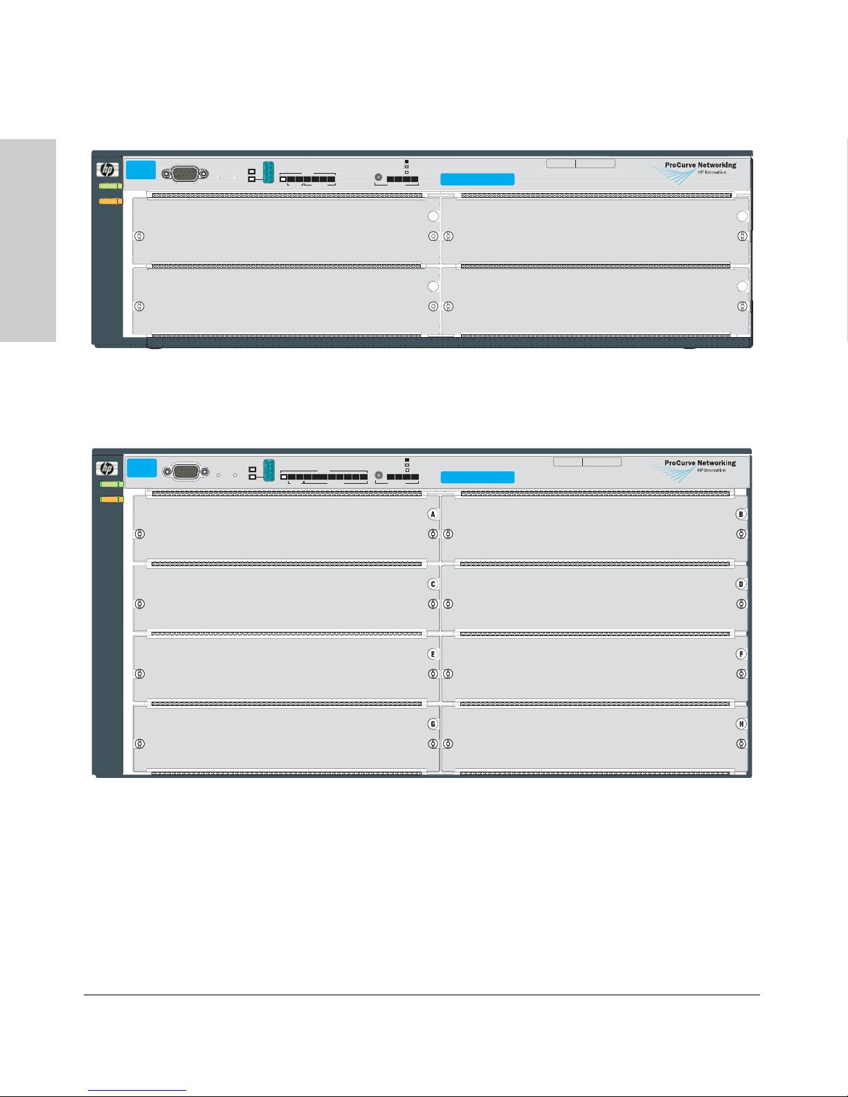
Figure 1-1. ProCurve Switch 4204vl (J8770A)
ProCurve
Switch 4208vl
J8773A
Power
Fault
Console
Self Test
ClearReset
Auxiliary Port
Status
1 2 A BCD E F G H
Fan
Power
Modules LED Mode
Spd mode: off = 10 Mbps
flash = 100 Mbps
on = 1000 Mbps
SpdFDxAct
!
Use vl modules only
Serial No.
System MAC Address
SG12345678 00-01-e7- 12-34- 56
Figure 1-2. ProCurve Switch 4208vl (J8773A)
1-2

Power
Fault
ProCurve
Switch 4202vl
J8772A
Console
Introducing the ProCurve Switch 4200vl Series
Switch 4200vl Options and Bundles
Introducing the ProCurve
Serial No.
Self Test
ClearReset
Auxiliary Port
Fan
Status
1 2 A B
Power
Modules
Use
vl Modules
only
Spd mode: off = 10 Mbps
flash = 100 Mbps
on = 1000 Mbps
FDx
Act
Spd
!
LED Mode
Mode
Link
1
3
Mode
Link
2
4
Mode
Link
25
27
7
5
6
29
31
10/100Base-TX Ports (1-72) all ports are HP Auto MDI-X
9
108
33
Mode
Link
13
11
Mode
Link
14
12
Mode
Link
35
37
15
17
16
18
41
39
System MAC Address
SG12345678 00-01-e7- 12-34- 56
21
19
22
20
43
45
23
24
47
Switch 4200vl Series
Power
Fault
ProCurve
Switch 4202v l
J8771A
Two slots for vl Modules
Figure 1-3. ProCurve Switch 4202vl-72 (J8772A)
Self Test
Console
ClearReset
Auxiliary Port
Fan
Status
1 2 A B
Power
Modules
Use
vl Modules
only
Spd mode: off = 10 Mbps
flash = 100 Mbps
on = 1000 Mbps
FDx
Act
Spd
!
LED Mode
Mode
Link
28
26
Link
49
Link
50
30
Mode
53
51
Mode
52
54
34
32
57
55
58
56
Mode
Link
38
36
Link
61
59
Link
62
60
42
40
Mode
65
63
Mode
66
64
46
44
67
68
48
69
71
72
70
72 fixed ports of 10/100-TX with
HP Auto MDI-X
Serial No.
System MAC Address
SG12345678 00-01-e7- 12-34- 56
Two slots for vl Modules
Figure 1-4. ProCurve Switch 4202vl-48G (J8771A)
48 fixed ports of 10/100/1000-T with
IEEE Auto MDI/MDI-X
1-3

Introducing the ProCurve Switch 4200vl Series
Switch 4200vl Options and Bundles
Supported Modules:
As of this printing, the supported vl modules are:
• 12-port 100-FX vl Module (J8763A)
• 16-port 10/100/1000-T vl Module (J8764A)
• 24-port 10/100-TX vl Module (J8765A)
• 1-port 10-GbE vl Module (J8766A) -- into which you can install the
Switch 4200vl Series
Introducing the ProCurve
supported transceivers:
– ProCurve 10-GbE X2-SC SR Optic (J8436A)
– ProCurve 10-GbE X2-SC LR Optic (J8437A)
– ProCurve 10-GbE X2-SC ER Optic (J8438A)
– ProCurve 10-GbE X2 CX4 Xcvr (J8440B)
• 24-port Gig-T vl module (J8768A)
• 4-port mini-GBIC vl Module (J8776A) -- into which you can install the
supported mini-GBICs:
– the ProCurve Gigabit-SX-LC Mini-GBIC (J4858B)
– the ProCurve Gigabit-LX-LC Mini-GBIC (J4859B)
– the ProCurve Gigabit-LH-LC Mini-GBIC (J4860B)
– the ProCurve Gigabit 1000Base-T Mini-GBIC (J8177B)
• 20-port Gig-T plus 4-port Mini-GBIC vl module (J9033A).
The supported mini-GBICs:
– the ProCurve Gigabit-SX-LC Mini-GBIC (J4858B)
– the ProCurve Gigabit-LX-LC Mini-GBIC (J4859B)
– the ProCurve Gigabit-LH-LC Mini-GBIC (J4860B)
– the ProCurve Gigabit 1000Base-T Mini-GBIC (J8177B)
– the ProCurve 100-FX SFP-LC Transceiver (J9054B)
1-4
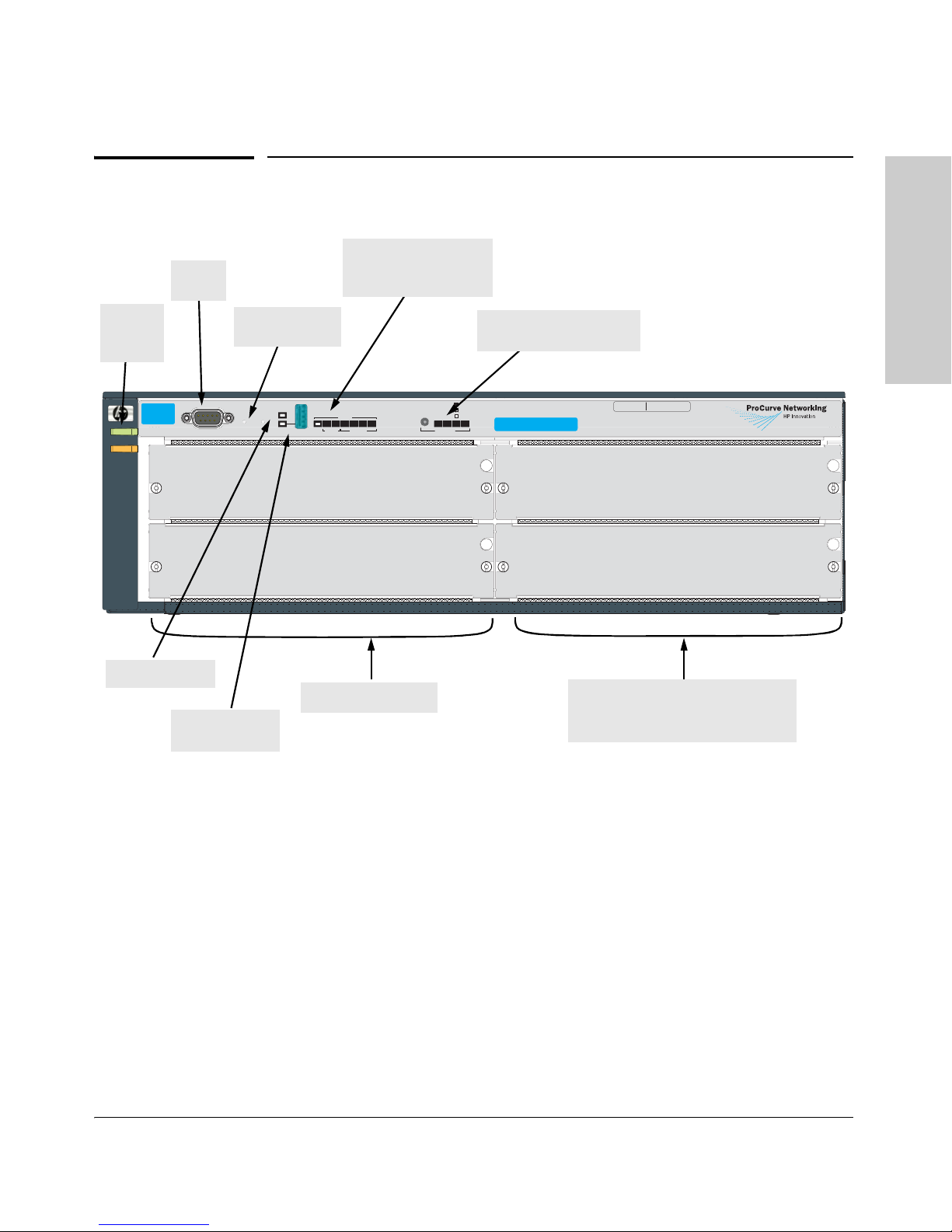
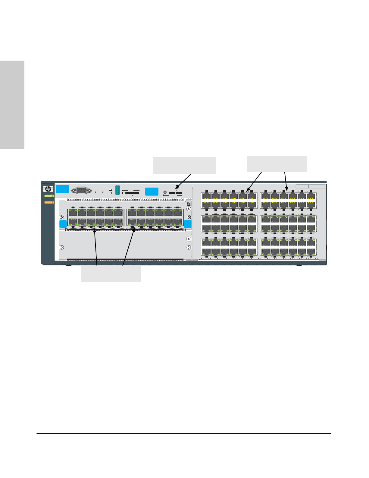
Console
Port
Front of the Switch
Status LEDs for the
Fans, Power Supplies,
and Switch Modules
Introducing the ProCurve Switch 4200vl Series
Front of the Switch
Introducing the ProCurve
Switch 4200vl Series
Power
and Fault
LEDs
ProCurve
Switch 4204vl
J8770A
Power
Fault
Self Test LED
Reset and Clear
Console
Auxiliary Port
and LED
buttons
Self Test
ClearReset
Auxiliary Port
Status
1 2 A BCD
Fan
Power
Modules
Switch Module slots
Spd mode: off = 10 Mbps
flash = 100 Mbps
on = 1000 Mbps
SpdFDxAct
!
LED Mode
LED Mode Select button
and indicator LEDs
Use vl modules only
A
C
Switch Module Slots or fixed ports with
Link and Mode LEDs for each port,
depending on which chassis you have
Serial No.
System MAC Address
SG12345678 00-01-e7- 12-34- 56
B
D
Figure 1-5. Switch 4204vl (J8770A)
This illustration shows the 4204vl, but the labeling and descriptions apply to
all of the ProCurve Switch 4200vl Series.
LEDs
As described in the next two tables, there are LEDs on the switch chassis and
on the switch modules/ports that keep you informed of the status of the switch
and the network connections.
1-5

Introducing the ProCurve Switch 4200vl Series
Front of the Switch
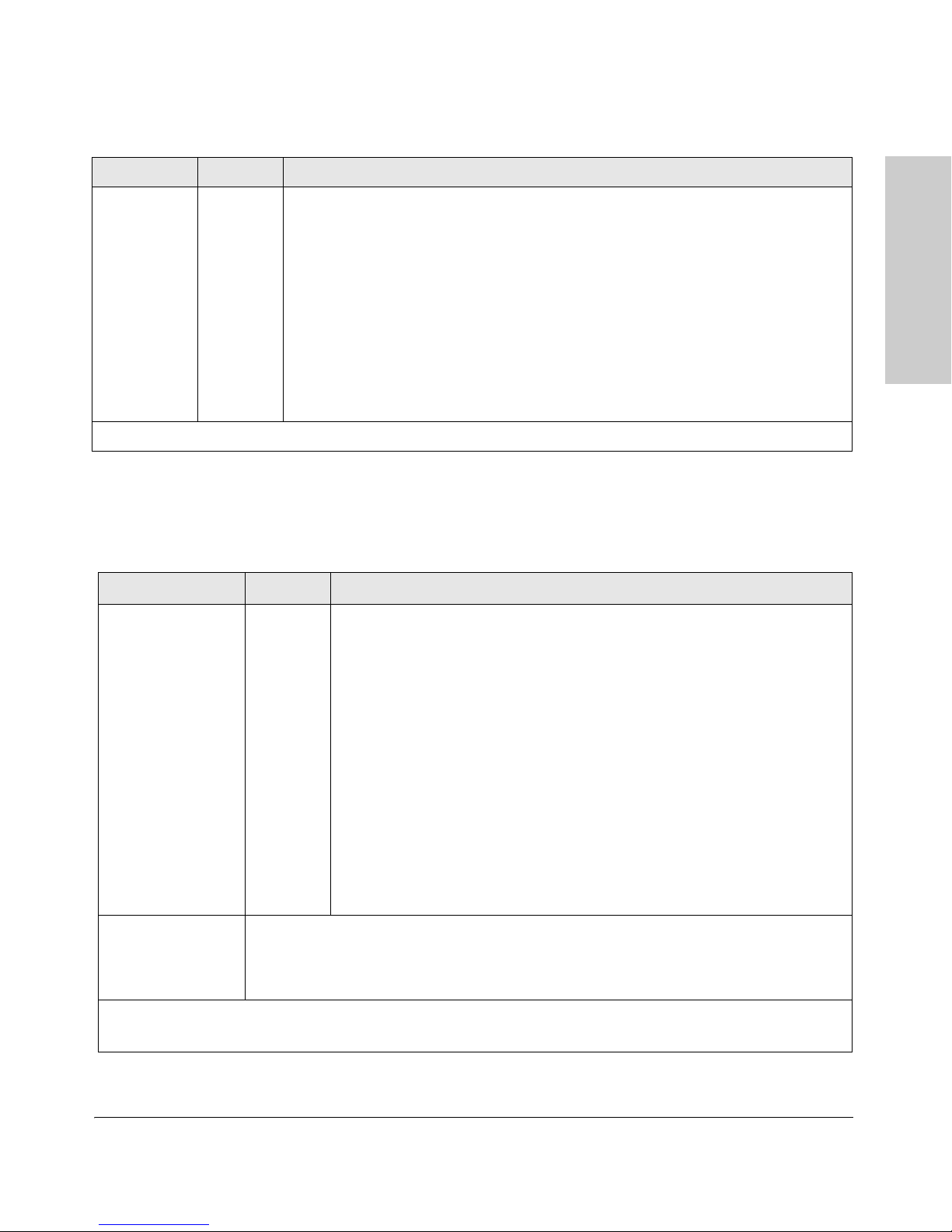
Table 1-1. Switch Chassis LEDs
LEDs State Meaning
Power
(green)
Fault
(orange)
Switch 4200vl Series
Introducing the ProCurve
On The switch is receiving power.
Off The switch is NOT receiving power.
Off The normal state; indicates that there are no fault conditions on the switch.
Flashing
1
A fault has occurred on the switch, one of the switch modules, an individual port, a power
supply, or a fan. The Status LED for the module or other component with the fault will flash
simultaneously.
On On briefly at the beginning of switch self test after the switch is powered on or reset. If on
for a prolonged time, the switch has encountered a fatal hardware failure, or has failed its
self test. See chapter 4, “Troubleshooting” for more information.
Self Test
(green)
Off The normal operational state; the switch is not undergoing self test.
On The switch self test and initialization are in progress after you have power cycled or reset
the switch. The switch is not operational until this LED goes off. The Self Test LED also
comes on briefly when you “hot swap” a module into the switch and the module is
automatically self tested.
1
Flashing
A component of the switch has failed its self test. The Status LED for that component, for
example a switch module, and the switch Fault LED will flash simultaneously.
Status/Fan
(green)
On The cooling fans are operating normally.
Flashing
1
One or more of the cooling fans have failed. The switch Fault LED will be flashing
simultaneously.
Status/Power
(green numbers
corresponding
to the power
supply
positions)
Status/
Modules
(green - letters
corresponding
to the switch
module slots)
On A power supply is installed in the position in the back of the switch corresponding to the
number, and the supply is plugged in to an active AC power source. As shipped, the switch
has a single power supply in position 1.
Off A power supply is not installed in the position corresponding to the number.
1
Flashing
The power supply installed in the position corresponding to the number is not plugged in
to an active AC power source, or has experienced a fault. The switch Fault LED will be
flashing simultaneously.
On A module is installed in the switch module slot corresponding to the letter and the module
is undergoing or has passed self test. This also occurs when you install a module when
the switch is already powered on (“hot swap”).
Off A module is not installed in the switch module slot corresponding to the letter.
1
Flashing
The module status LED flashes very briefly when a module is being hot swapped. If the LED
flashes for a prolonged time, the module in the slot corresponding to the letter has failed
self test or encountered some other fault condition. See chapter 4, “Troubleshooting” for
a more information.
1-6
Introducing the ProCurve Switch 4200vl Series
Front of the Switch
LEDs State Meaning
LED Mode
Select
(3 green LEDs)
1
The flashing behavior is an on/off cycle once every 1.6 seconds, approximately.
Act Indicates the port Mode LEDs are displaying network activity information.
FDx Indicates the port Mode LEDs are lit for ports that are in Full Duplex Mode.
Spd Indicates the port Mode LEDs are displaying the connection speed at which each port is
operating:
• if the port Mode LED is off, the port is operating at 10 Mbps.
• if the port Mode LED is flashing, the port is operating at 100 Mbps.
• if the port Mode LED is on continuously, the port is operating at 1000 Mbps.
!
Indicates that specific error packets are being detected on the port. In this mode, the Mode
LED for the port will flash briefly for each error packet that is detected, for example CRC
errors or late collisions.
Table 1-2. Switch Module/Port LEDs
The following LEDs are located on the modules themselves or fixed ports
depending on which switch chassis you have, one pair for each port.
LED State Meaning
Link On Indicates the port is enabled and receiving a link beat signal (for the twisted-pair
ports), or a strong enough light level (for the fiber-optic ports) from the connected
device.
Introducing the ProCurve
Switch 4200vl Series
Off One of these conditions exists:
• no active network cable is connected to the port
• the port is not receiving link beat or sufficient light
• the port has been disabled through the switch console, the web browser
interface, ProCurve Manager, or other network management tool.
1
Flashing
Fast
Flashing
Mode Depending on the mode selected, displays the following: network activity information, whether
the port is configured for Full Duplex operation, port connection speed, or whether network
errors are occurring on the port. See “LED Mode Select Button and Indicator LEDs” below for
more information.
1
The flashing behavior is an on/off cycle once every 1.6 seconds, approximately.
2
The fast flashing behavior is an on/off cycle once every 0.8 seconds, approximately.
The port has failed self test due to hardware failure or because the port type
requires newer software in order to be recognized. The switch Fault, Self Test
LEDs, and appropriate module status LEDs will flash simultaneously. The Fault
LED will flash only for hardware failure.
Port security has disabled the port.
2
1-7
Introducing the ProCurve Switch 4200vl Series
Front of the Switch
LED Mode Select Button and Indicator LEDs
To optimize the amount of information that can be displayed for each of the
switch ports, the Switch 4200vl Series use a Mode LED for each port. The
operation of this LED is controlled by the LED Mode Select button on the
switch chassis, and the current selection is indicated by the mode indicator
LEDs near the button. The default Mode LED position is Activity (Act). Press
the button to change from one mode to the next. After ten minutes, the Mode
Switch 4200vl Series
Introducing the ProCurve
button setting reverts back to the default setting. The Mode Select button and
LEDs are the same for all the Switch 4200vl Series. The following example is
of a J8772A, 4202vl-72.
Power
Fault
ProCurve
Switch 4202vl
J8772A
ProCurve
10/100-TX
vl Module
Console
Link Mode Link Mode
31
Link Mode Link Mode
J8765A
42
Self Test
ClearReset
10/1
5
6
Module Mode LEDs
(one for each port)
Figure 1-6. Mode Select and LEDs
■ If the Activity (Act) indicator LED is lit, each port Mode LED displays
■ If the Full Duplex (FDx) indicator LED is lit, the port Mode LEDs light for
■ If the Speed (Spd) indicator LED is lit, the port LEDs behave as follows
■ If the attention (!) indicator LED is lit, each Mode LED lights briefly for
Mode LEDs
(one for each port)
Mode
Link
13
11
12
35
36
59
60
15
Mode
Link
14
16
Mode
Link
39
37
Mode
Link
40
38
Mode
Link
61
63
Mode
Link
62
64
17
18
41
42
65
66
Serial No.
System MAC Address
SG12345678 00-01-e7- 12-34- 56
21
19
22
20
43
45
46
44
69
67
68
70
23
24
47
48
71
72
Auxiliary Port
00Base-TX P
1197
12108
Status
1 2 A B
Fan
Power
Modules
orts — all ports are HP A uto MDI-X
13
14
LED Mode Select button
and indicator LEDs
Spd mode: off = 10 Mbps
21
22
Act
LED Mode
FDx
flash = 100 Mbps
on = 1000 Mbps
Spd
!
23
24
Mode
Link
1
3
A
vl
Module
Mode
Link
2
4
Mode
Link
25
27
Mode
Link
28
26
Mode
Link
51
49
Mode
Link
52
50
Use
vl Modules
only
15
16
19
17
20
18
7
5
8
6
29
31
30
32
55
53
54
56
10/100Base-TX Ports (1-72) all ports are HP Auto MDI-X
9
10
33
34
57
58
activity information for the port—it flickers as network traffic is received
and transmitted through the port.
those ports that are operating in full duplex.
to indicate the connection speed for the port:
• Off = 10 Mbps
• Flashing = 100 Mbps
• On = 1000 Mbps
each network event that could require operator attention, for example,
late collisions or CRC errors.
1-8

Introducing the ProCurve Switch 4200vl Series
Front of the Switch
Console Port
This port is used to connect a console to the switch by using the serial cable
supplied with the switch. This connection is described under “Connecting a
Console to the Switch” in chapter 2, “Installing the Switch 4200vl Series”. The
console is a full-featured interface that can be used to configure, monitor, and
troubleshoot the switch. It can be run on a PC, laptop, or handheld device
emulating a VT-100 terminal, or on a standard VT-100 terminal.
Reset Button
This button is used to reset the switch while it is powered on. This action clears
any temporary error conditions that may have occurred, executes the switch
self test, and resets all network activity counters to zero. The counters are
displayed in the switch console interface, the switch web browser interface,
and through SNMP network management applications, such as ProCurve
Manager.
Press the Reset button also after changing the module type that is installed in
any of the switch module slots while the switch is powered on. In this case,
the switch must be reset to initialize the new module type. See “Hot Swapping
Switch Modules” on page 2-22.
Introducing the ProCurve
Switch 4200vl Series
Clear Button
This button is used for the following purposes:
■ Deleting Passwords - When pressed by itself for at least one second, the
Clear button deletes any switch console access passwords that you may
have configured. Use this feature if you have misplaced the password and
need console access.
This button is provided for your convenience, but its presence means that
if you are concerned with the security of the switch configuration and
operation, you should make sure the switch is installed in a secure
location, such as a locked wiring closet.
■ Restoring Factory Default Configuration - When pressed with the
Reset button in a specific pattern, the Clear button clears any configuration changes you may have made through the switch console, the web
browser interface, or SNMP management, and restores the factory default
configuration to the switch. For the specific method to restore the factory
default configuration, see “Restoring the Factory Default Configuration”
in chapter 4, “Troubleshooting” of this manual.
1-9
Introducing the ProCurve Switch 4200vl Series
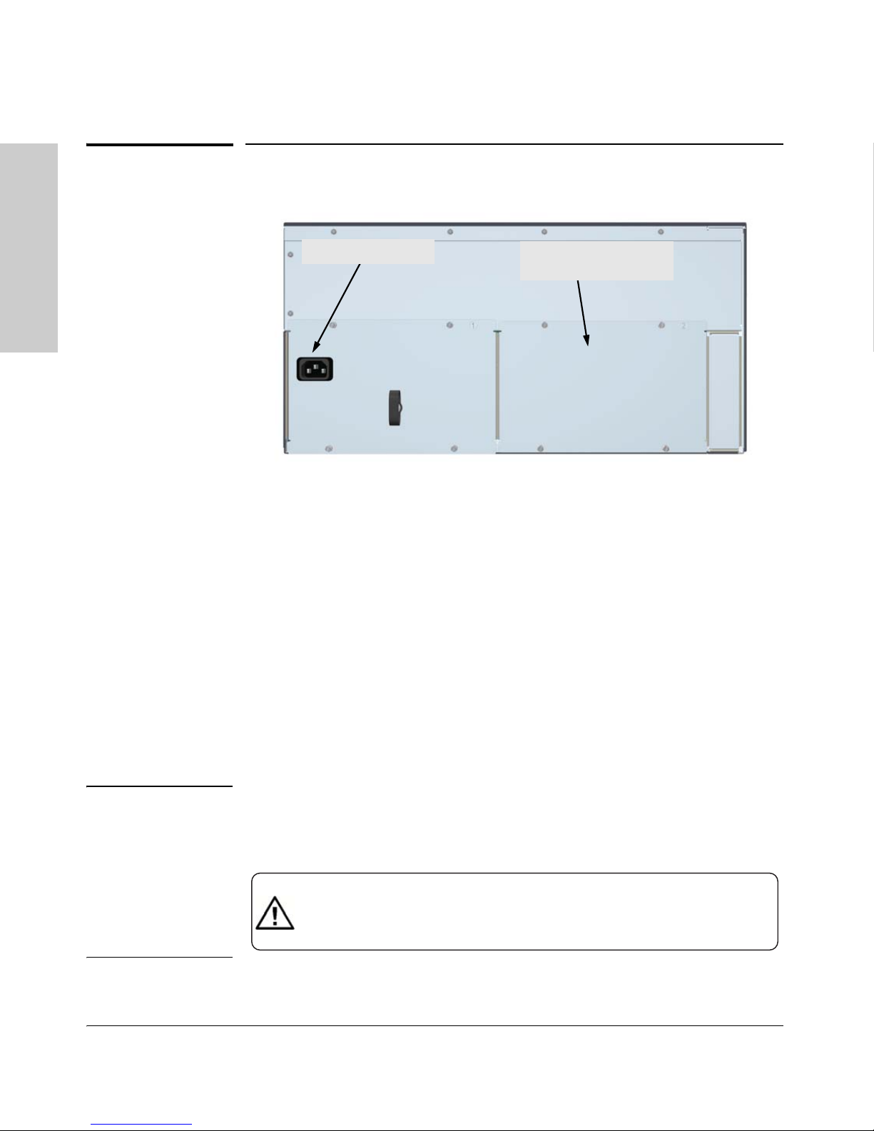
Back of the Switch
Back of the Switch
.
AC power connector
Switch 4200vl Series
Introducing the ProCurve
Figure 1-7. Example showing back of Switch 4208vl (J8773A)
slot for installing optional
redundant power supply
Power Connector
The Switch 4200vl Series do not have a power switch; they are powered on
when connected to an active AC power source. The switches automatically
adjust to any voltage between 100-127 and 200-240 volts and either 50 or 60
Hz. There are no voltage range settings required.
Slot for Redundant Power Supply
A second, load-sharing redundant power supply (ProCurve switch RPS,
J4839A) can be installed in the back of the Switch 4200vl Series. To provide
true redundancy, this second power supply should be connected to a different
AC power source from the other supply. Then, if one AC power source fails,
the switch will continue to run.
Caution The switch redundant power supply is hot swappable, but, as indicated by the
caution statement on the power supply, it must be disconnected from AC
power before being installed or removed.
Caution:
.
Refer to the installation guide for proper power cord selection.
.
Disconnect AC power from this power supply BEFORE installing or removing
the supply. Otherwise, damage to the equipment may result.
Because the switch can run on a single supply, removing a redundant supply
will not interrupt switch operation.
1-10

Introducing the ProCurve Switch 4200vl Series
Switch Features
Switch Features
The features of the Switch 4200vl Series include:
■ 2, 4 or 8 slots for installing any of the available Switch vl Modules.
the modules can be installed in any order and in any combination and can
be “hot swapped”.
■ the supported mini-GBICs can be hot swapped into the mini-GBIC vl
Module.
■ the supported transceivers can be hot swapped into the 10-GbE vl Module.
■ high performance -- 76.8 Gbps switching fabric delivering 48 Mpps
throughput.
■ plug-and-play networking—all ports are enabled—just connect the
network cables to active network devices and your switched network is
operational.
■ automatic learning of the network addresses in the switch’s 10,000-
address forwarding table, with configurable address aging value.
■ full-duplex operation available on all ports.
■ easy management of the switch through several available interfaces:
• web browser interface—an easy to use built-in graphical interface
that can be accessed from common web browsers.
• console interface—a full featured, easy to use, VT-100 terminal interface for switch management, accessible out-of-band and by telnet.
The console includes complete switch management through a
command line interface (CLI) with the most basic configuration
parameters also accessible through an intuitive menu interface.
• ProCurve Manager—an SNMP-based graphical interface that is used
to manage your entire network, included with your new switch.
• supported by HP OpenView ProCurve Network Manager—an HP
OpenView application that accurately displays your switch on
network maps and provides a graphical interface for configuring and
monitoring your switch.
■ support for the Spanning Tree Protocol to eliminate network loops.
■ support for up to 256 IEEE 802.1Q-compliant VLANs so you can divide the
attached end nodes into logical groupings that fit your business needs.
Introducing the ProCurve
Switch 4200vl Series
1-11

Introducing the ProCurve Switch 4200vl Series
Switch Features
■ Layer 3 routing functionality:
• IP static routes
•IRDP
• DHCP relay
■ support for many other advanced features to enhance network perfor-
mance, security, and control— for a description, see the Management and
Configuration Guide and the Advanced Traffic Management Guide for
Switch 4200vl Series
your switch, available on the ProCurve Web site.
Introducing the ProCurve
1-12

Installing the Switch 4200vl Series
The ProCurve Switch 4200vl Series are easily installed. They come with an
accessory kit that includes the brackets for mounting the switch in a standard
19-inch telco rack, in an equipment cabinet, or on a wall. The switches have
rubber feet already attached so they can be securely located on a horizontal
surface. This chapter shows you how to install your Switch 4200vl Series.
Included Parts
The Switch 4200vl Series have the following components shipped with them:
■ ProCurve Switch 4200vl Series Installation and Getting Started Guide,
this manual
2
Installing the Switch 4200vl
Series
■ ProCurve Manager - CD ROM and booklet
■ Customer Support/Warranty booklet
■ Accessory kit 5065-6521 for the:
• 8-slot Switch 4208vl
• Switch 4208vl-64G
• Switch 4208vl-96
• Switch 4208vl-72GS
■ Accessory kit 5064-9943 for the:
• 4-slot Switch 4204vl
• Switch 4202vl-48G
• Switch 4202vl-72
• Switch 4204vl-48GS
■ Each kit contains:
• two mounting brackets
• six 10 mm M4 screws to attach the mounting brackets to the switch
• four 5/8-inch number 12-24 screws to attach the switch to a rack
■ Console cable
2-1
Installing the Switch 4200vl Series
Included Parts
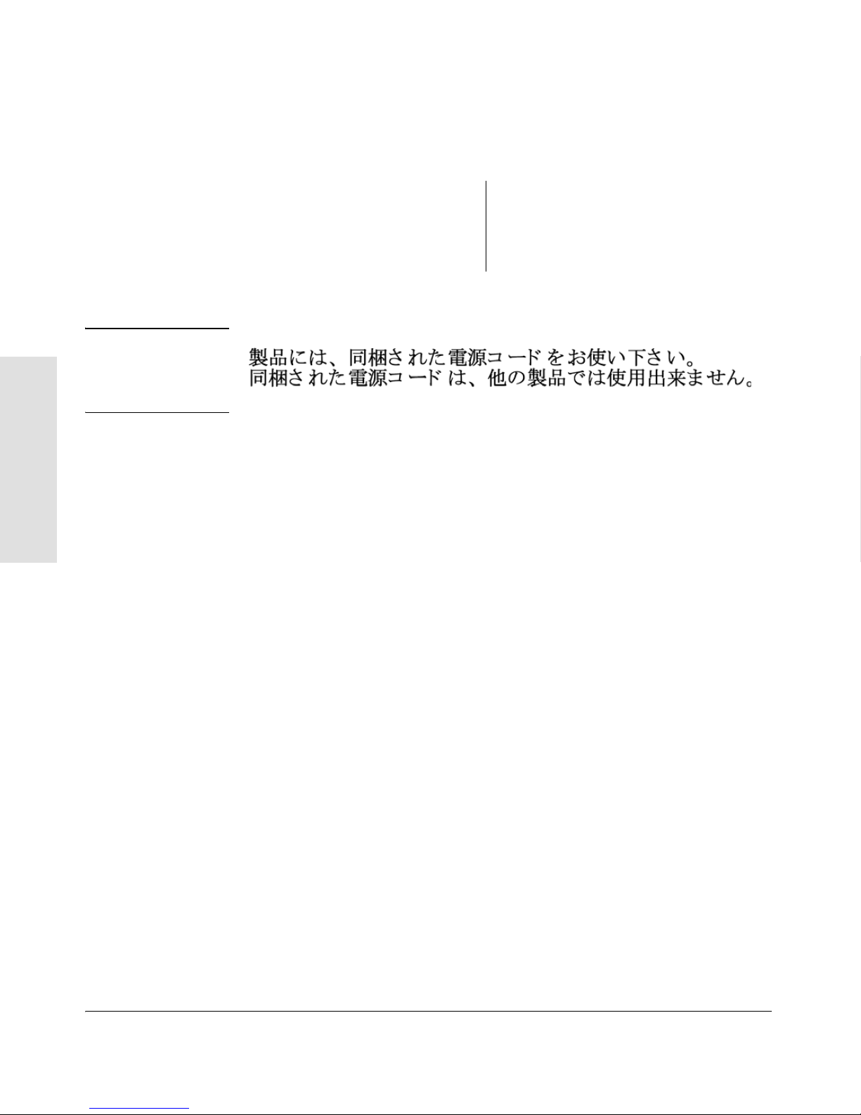
■ Power cord, one of the following:
Series
Installing the Switch 4200vl
Japan Power
Cord Warning
Australia/New Zealand
China
Continental Europe
Denmark
Japan
8120-6803
8120-8377
8120-6802
8120-6806
8121-0606
Switzerland
United Kingdom/
Hong Kong/Singapore
United States/Canada/Mexico
8120-6807
8120-8709
8121-0605
2-2

Installing the Switch 4200vl Series
Installation Procedures
Installation Procedures
Summary
Follow these easy steps to install your switch. The rest of this chapter provides
details on these steps.
1. Prepare the installation site (page 2-6). Make sure the physical environment into which you will be installing the switch is properly prepared
including having the correct network cabling ready to connect to the
switch, and having a good location for the switch. See page 2-4 for some
installation precautions.
2. Install switch modules (page 2-8). The Switch 4200vl Series have two,
four or eight universal slots for installing any of the ProCurve Switch vl
modules. Depending on where you will install your Series 4200vl Switch,
it may be easier to install the modules first. The modules are “hot swappable” though, so they can also be installed and removed after the switch
is powered on.
Installing the Switch 4200vl
Series
Note Make sure you use only ProCurve Switch vl Modules in your Switch 4200vl
Series.
3. (Optional) Install second power supply (page 2-10). The Switch
4200vl Series have a slot in the back for installing a second, load-sharing
power supply. If you have purchased this supply, it may be easier to install
it before mounting the switch.
4. Verify the switch passes self test (page 2-12). This is a simple process
of plugging the switch into a power source and observing that the LEDs
on the switch’s front panel and on the modules show correct operation.
5. Mount the switch (page 2-14). The Switch 4200vl Series can be mounted
in a 19-inch telco rack, in an equipment cabinet, on a wall, or on a
horizontal surface. There are some limitations to the wall mounting
orientations that are supported. Please see the installation details for
more information.
6. Connect power to the switch (page 2-19). Once the switch is mounted,
plug it in to the nearby main power source.
7. Connect the network devices (page 2-19). Using the appropriate
network cables, connect other switches, hubs, routers, computers,
servers, printers, and other network devices to the switch ports. For more
information, see “Connect the Network Devices” on page 2-19.
2-3

Installing the Switch 4200vl Series
Installation Procedures
Note The 10/100Base-TX ports on the10/100-TX vl Module have the HP Auto
MDI-X feature, and the 10/100/1000Base-T ports on the Gig-T vl Module
comply with IEEE 802.3ab standard which includes the Auto MDI/MDIX feature. These two features operate the same and allow you to use
straight-through twisted-pair cable for all of your twisted-pair network
connections.
8. (Optional) Connect a console to the switch (page 2-20). You may
wish to modify the switch’s configuration, for example, to configure an IP
address so it can be managed using a web browser or from an SNMP
network management station. Configuration changes can be made easily
through the switch’s console interface.
At this point, the switch is fully installed. See the rest of this chapter if you
need more detailed information on any of these installation steps.
Installation Precautions
Series
Installing the Switch 4200vl
WARNINGS
Follow these precautions when installing the ProCurve Series 4200vl Switch:
■ Devices installed in a rack or cabinet should be mounted as low
as possible, with the heaviest device at the bottom and progressively lighter devices installed above.
The rack or cabinet should be adequately secured to prevent it
from becoming unstable and/or falling over.
■ Ensure a cover plate is installed in any empty switch power
supply slot. A cover plate is required for safe operation, and
to ensure proper switch cooling.
■ To avoid energy and mechanical hazards, never allow any part
of your body, jewelry, tool, or other foreign object to enter any
module or power supply slots.
■ Ensure that for any switch slot into which no module is
installed, the cover plate is installed to cover the slot. A cover
plate is required for safe operation, and to ensure proper
switch cooling. For safety, you should never have more than
one module slot uncovered at a time while the switch is
powered on.
2-4

Installing the Switch 4200vl Series
Installation Precautions (continued)
Installation Procedures
Cautions
■ Ensure the power source circuits are properly grounded, then use the
power cord supplied with the switch to connect it to the power source.
If your installation requires a different power cord than the one supplied
with the switch and power supply, be sure the cord is adequately sized
for the switch’s current requirements. In addition, be sure to use a power
cord displaying the mark of the safety agency that defines the regulations
for power cords in your country. The mark is your assurance that the
power cord can be used safely with the switch and power supply.
■ When installing the switch, note that the AC outlet should be near the
switch and should be easily accessible in case the switch must be
powered off.
■ Ensure the switch does not overload the power circuits, wiring, and over-
current protection. To determine the possibility of overloading the supply
circuits, add together the ampere ratings of all devices installed on the
same circuit as the switch and compare the total with the rating limit for
the circuit. The maximum ampere ratings are usually printed on the
devices near the AC power connectors.
■ Do not install the switch in an environment where the operating ambient
temperature might exceed 40°C (104°F).
Installing the Switch 4200vl
Series
■ Allow three to four inches of space around the sides and back of the
switch to make sure the air flow for the switch is not restricted.
2-5

Installing the Switch 4200vl Series
Installation Procedures
1. Prepare the Installation Site
Cabling Infrastructure
Ensure the cabling infrastructure meets the necessary network specifications.
See the following table for cable types and lengths, and see appendix B,
“Switch Ports and Network Cables” on page B-1 for more information:
Table 2-1. Summary of Cable Types to Use with the Switch
Port Type Cable Type Length Limits
Twisted-Pair Cables
Series
Installing the Switch 4200vl
10/100/1000Base-T For either 10, 100 Mbps or 1000 Mbps
operation:
Category 5 or better, 100-ohm UTP or shielded
twisted-pair (STP) balanced cable. For 1000
Mbps (gigabit) operation, Category 5e cabling
or better is recommended.
Fiber Optic Cables
Gigabit-SX
(on Gigabit-SX-LC
mini-GBIC)
Gigabit-LX
(on Gigabit-LX-LC
mini-GBIC)
Multimode fiber-optic cables fitted with LC
connectors
Single-mode fiber-optic cables fitted with LC
connectors.
The multimode cables specified for the GigabitSX mini-GBIC may also be used, but a modeconditioning patch cord may be needed — See
the Installation Guide that came with your
module for more information.
100 meters
Note: The ProCurve Gig-T vl Modules are
compatible with the IEEE 802.3ab standard
including the “Auto MDI/MDI-X” feature,
which allows use of either straight-through
or crossover twisted-pair cables for
connecting to any network devices
including end nodes, such as computers, or
to other switches, hubs, and routers.
The Auto MDI/MDI-X feature only works
when the port is in auto-negotiation mode.
220 meters to 550 meters depending on the
cable used. See “Fiber-Optic Cables” on
page B-3 for more information.
• single-mode cable = 10 kilometers
• multimode cable = 550 meters
Gigabit-LH
(on Gigabit-LH-LC
mini-GBIC)
Note:
Gigabit-LH - The transmission distances are dependent on the particular fiber loss and coupling loss involved, among
other factors, and can be estimated from the optical loss budget. For distances less than 20km, a 10dB attenuator must
be used. For distances between 20km and 40km, a 5dB attenuator must be used. Attenuators can be purchased from
most cable vendors.
The same single-mode fiber-optic cables a s for
Gigabit-LX.
2-6
• 70 kilometers

Installing the Switch 4200vl Series
Port Type Cable Type Length Limits
Installation Procedures
10-GbE SR Multimode fiber-optic cable designed for
Gigabit Ethernet: 62.5/125 μm (core/cladding)
diameter or 50/125 μm, low metal content,
complying with the ITU-T G.652 and ISO/IEC
793-2 Type B1 standards.
10-GbE LR 9/125 μm (core/cladding) diameter, low metal
content, single mode fiber-optic cables,
complying with the ITU-T G.652 and ISO/IEC
793-2 Type B1 standards.
10-GbE ER 9/125 μm (core/cladding) diameter, low metal
content, single mode fiber-optic cables,
complying with the ITU-T G.652 and ISO/IEC
793-2 Type B1 standards.
CX4 Media
Converter
Optical Media
Converter
12 fiber 50/125 μm (core/cladding) diameter,
multimode Fiber ribbon cable. 12 fiber 62.5/125
μm (core/cladding) diameter, multimode Fiber
ribbon cable is also supported.
Copper Cables
■ 62.5 μm cable:
• 160 Mhz/km = 2-26 meters
• 200 Mhz/km = 2-33 meters
■ 50 μm cable:
• 400 Mhz/km = 2-66 meters
• 500 Mhz/km = 2-82 meters
• 2000 Mhz/km = 2-300 meters
single-mode cable: 2-10 kilometers
single-mode cable: 2-30 kilometers (40
kilometers, on an engineered fiber optic link
that meets standards in the specification).
50 μm cable or 62.5 μm cable: 300 meters
Installing the Switch 4200vl
Series
Port Type Cable Specifications Connector Type
CX4 Shielded twisted-pair cables complying with
the 802.3ak standard.
Installation Location
Before installing the switch, plan its location and orientation relative to other
devices and equipment:
■ In the front of the switch, allow at least 7.6 cm (3 inches) of space for the
twisted-pair and fiber-optic cabling.
■ In the back of the switch, allow at least 10.2 cm (4 inches) of space for the
power cord and cooling.
■ On the sides of the switch, leave at least 7.6 cm (3 inches) for cooling.
CX4
2-7

Installing the Switch 4200vl Series
Installation Procedures
2. Install Switch vl Modules
Install switch modules into the slots as shown in the following illustration. For
installation details, see the instructions in the manual that comes with the
module.
Caution Make sure you install only ProCurve Switch vl Modules. Switch gl/xl Modules
will fit into your Switch vl slots, but they will not operate.
Avoid any electrostatic discharge problems by handling the modules only by
their bulkheads.
The slot cover can be removed, and the module can be installed with either a
flat-bladed or Torx T-10 screwdriver. Retain the slot cover for future use.
Series
Installing the Switch 4200vl
Module
Installation
Notes
■ Any of the supported Switch vl Modules can be installed in any of the slots.
■ You can install, exchange, or remove modules after the switch has been
powered on. Whenever a module is installed during this process, it is
initialized and tested for correct operation. During this process, the switch
Self Test LED is on. If you hot swap another module while the switch is
initializing and testing the first module, it is possible to cause the first
module or the entire switch to be reset. To prevent the modules or switch
from being reset when you must hot swap multiple modules, follow these
precautions:
• Do not install/remove any modules from the switch while the switch
Self Test LED is lit.
• Before removing or installing any modules, make sure that all
network cables are disconnected from the module.
See “Hot Swapping the Switch Module” on page 2-22.
■ The modules employ “low-force” connectors. Using high force to insert
the modules is not needed and should not be used.
■ Ensure you fully insert the modules. That is, press the module into the slot
until the bulkhead on the module is contacting or is very close to
contacting the front face of the switch chassis.
■ Once the module is fully inserted, ensure that you screw in the two
retaining screws to secure the module in place. The screws should be
tightened until they are secure, but not overtightened.
■ If you do not use one or more of the slots, ensure the slot cover plate is
still attached over the slot for safe operation and proper switch cooling.
For safety, you should not have more than one module slot uncovered at
a time.
2-8
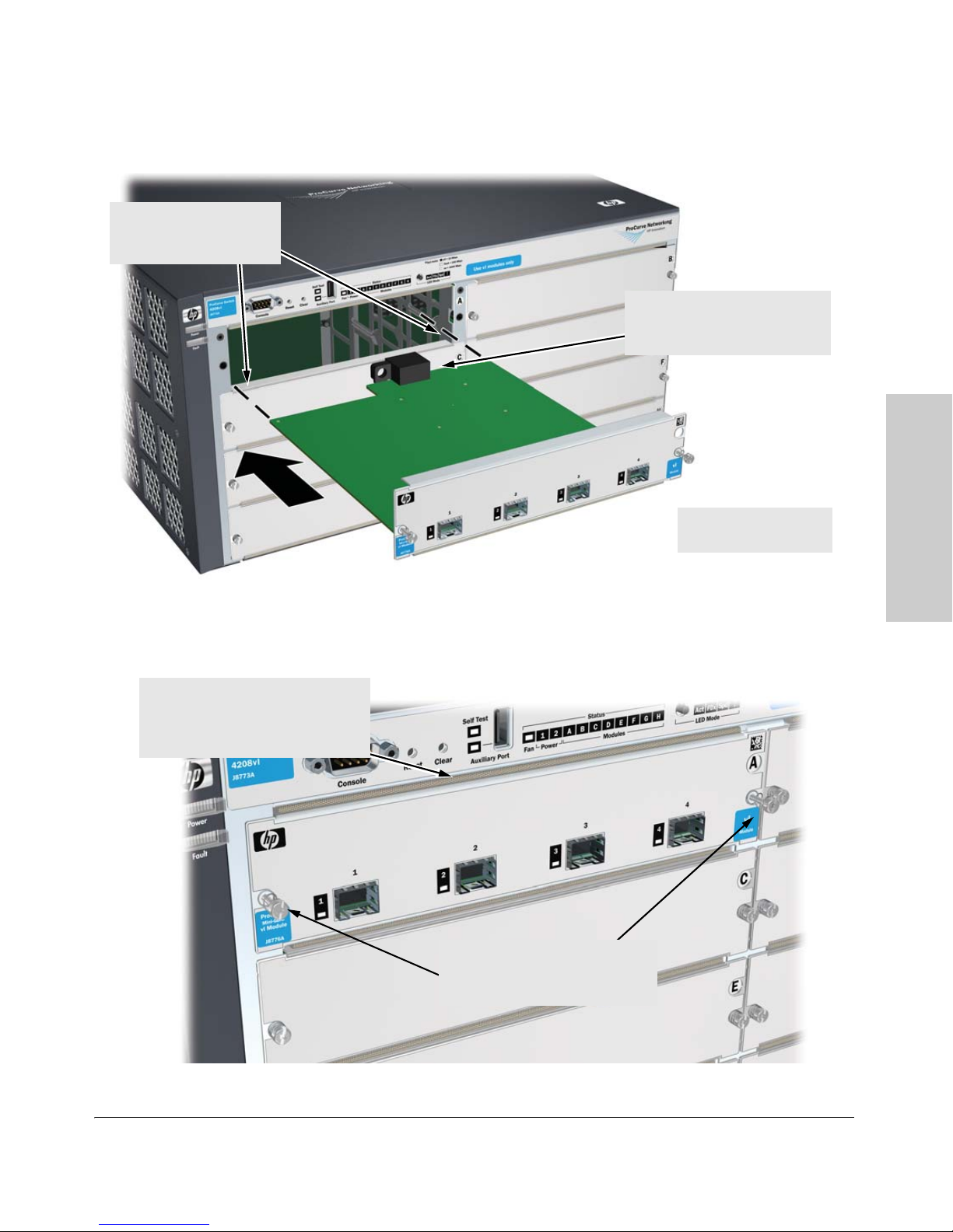
insert module into the
guides and slide it in until
it is fully inserted
Installing the Switch 4200vl Series
Installation Procedures
“Low-force” connector.
High insertion force is not
needed and should not be used
Installing the Switch 4200vl
Series
for best results,
push near both screws
Figure 2-1. Installing a module
the module is fully inserted when
the module bulkhead is contacting,
or very close to contacting
the face of the switch
tighten the retaining screws on
the module until they are secure,
but do not overtighten them
Figure 2-2. Tighten module retaining screws
2-9
Series
Installing the Switch 4200vl Series
Installation Procedures
3. (Optional) Install Second Power Supply
A second, load-sharing redundant power supply (ProCurve Switch gl/xl/vl
RPS, J4839A) can be installed in the back of the switch. To provide true
redundancy, this second power supply should be connected to a different AC
power source from the other supply. Then, if one AC power source fails, the
switch will continue to run. Each supply provides enough power to operate a
fully loaded switch, so even if one fails, the switch will continue to operate
normally.
Install the second power supply as shown in the illustration on the next page.
The slot cover can be removed with either a flat-bladed or Torx T-10 screwdriver. Retain the slot cover for future use.
Caution The switch power supplies are hot swappable; they can be installed while the
switch is receiving power from the supply in the other slot. But, as indicated
by the caution statement on the power supply, the supply must not be
connected to AC power before being installed.
Installing the Switch 4200vl
Caution:
.
Refer to the installation guide for proper power cord selection.
.
Disconnect AC power from this power supply BEFORE installing or removing
the supply. Otherwise, damage to the equipment may result.
For safety and proper switch cooling, if either of the power supply slots are
not being used, make sure to attach the cover plate over the slot. Please see
the “Installation Precautions” on page 2-4 for more information.
For installation details, see the instructions in the manual that comes with the
power supply.
2-10
 Loading...