

HP ProCurve Switch 2626-PWR, J8164A, ProCurve Switch 2650-PWR, J8165A, ProCurve Switch 2600-8-PWR with Gigabit Uplink Installation And Getting Started Manual
...
ProCurve Series
2600 Switches
PoE
Power over Ethernet Devices
Installation and
Getting Started Guide
www.procurve.com


ProCurve Series 2600 Switches
Installation and Getting Started Guide

© Copyright 2001, 2005, 2008 Hewlett-Packard Development
Company, L.P. The information contained herein is subject to
change without notice.
This document contains proprietary information, which is
protected by copyright. No part of this document may be
photocopied, reproduced, or translation into another language
without the prior written consent of Hewlett-Packard.
Publication Number
5991-2165, January 2008
Applicable Products
ProCurve Switch 2626-PWR (J8164A)
ProCurve Switch 2650-PWR (J8165A)
ProCurve Switch 2600-8-PWR with Gigabit Uplink (J8762A)
ProCurve 600 Redundant and External
Power Supply
ProCurve 610 External Power Supply (J8169A)
ProCurve Switch 2626 (J4900B)
ProCurve Switch 2650 (J4899B)
(J8168A)
Trademark Credits
Windows® is a US registered trademark of Microsoft
Corporation.
Disclaimer
HEWLETT-PACKARD COMPANY MAKES NO WARRANTY
OF ANY KIND WITH REGARD TO THIS MATERIAL,
INCLUDING, BUT NOT LIMITED TO, THE IMPLIED
WARRANTIES OF MERCHANTABILITY AND FITNESS
FOR A PARTICULAR PURPOSE. Hewlett-Packard shall not be
liable for errors cont ained herein or for incidental or c onsequential
damages in connection with the furnishing, performance, or use
of this material.
The only warranties for HP products and services are set forth in
the express warranty st atements accompanying such products and
services. Nothing herein should be construed as constituting an
additional w arranty. HP shall not be liable for technical or editor ial
errors or omissions contained herein.
Hewlett-Packard assumes no responsibility for the use or
reliability of its software on equipment that is not furnished by
Hewlett-Packard.
Warranty
See the Customer Support/Warranty booklet included with the
product.
A copy of the specific warranty terms applicable to your HewlettPackard products and replacement parts can be obt ained from your
HP Sales and Service Office or authorized dealer.
Hewlett-Packard Company
8000 Foothills Boulevard, m/s 5552
Roseville, California 95747-5552
http://www.procurve.com

Contents
1 Introducing the Switch
Front of the Switch . . . . . . . . . . . . . . . . . . . . . . . . . . . . . . . . . . . . . . . . . . . . . . 1-3
Network Ports . . . . . . . . . . . . . . . . . . . . . . . . . . . . . . . . . . . . . . . . . . . . . . 1-4
LEDs . . . . . . . . . . . . . . . . . . . . . . . . . . . . . . . . . . . . . . . . . . . . . . . . . . . . . . 1-4
Port LEDs . . . . . . . . . . . . . . . . . . . . . . . . . . . . . . . . . . . . . . . . . . . . . . 1-6
Multiple-Display Port LEDs - Port LED View or
LED Mode Select Button and Indicator LEDs . . . . . . . . . . . . . . . . 1-7
Reset Button . . . . . . . . . . . . . . . . . . . . . . . . . . . . . . . . . . . . . . . . . . . . . . . 1-9
Clear Button . . . . . . . . . . . . . . . . . . . . . . . . . . . . . . . . . . . . . . . . . . . . . . . . 1-9
Back of the Switch . . . . . . . . . . . . . . . . . . . . . . . . . . . . . . . . . . . . . . . . . . . . . 1-10
Console Port . . . . . . . . . . . . . . . . . . . . . . . . . . . . . . . . . . . . . . . . . . . . . . 1-11
Power Connector . . . . . . . . . . . . . . . . . . . . . . . . . . . . . . . . . . . . . . . . . . 1-11
Switch Features . . . . . . . . . . . . . . . . . . . . . . . . . . . . . . . . . . . . . . . . . . . . . . . 1-11
2 Installing the Switch
Included Parts . . . . . . . . . . . . . . . . . . . . . . . . . . . . . . . . . . . . . . . . . . . . . . . . . . 2-1
Installation Procedures . . . . . . . . . . . . . . . . . . . . . . . . . . . . . . . . . . . . . . . . . . 2-3
Installation Precautions . . . . . . . . . . . . . . . . . . . . . . . . . . . . . . . . . . . . . . 2-4
1. Prepare the Installation Site . . . . . . . . . . . . . . . . . . . . . . . . . . . . . . . . 2-5
2. Installing or Removing mini-GBICs . . . . . . . . . . . . . . . . . . . . . . . . . . 2-7
3. Verify the Switch Passes Self Test . . . . . . . . . . . . . . . . . . . . . . . . . . . 2-9
LED Behavior . . . . . . . . . . . . . . . . . . . . . . . . . . . . . . . . . . . . . . . . . . 2-10
4. Mount the Switch . . . . . . . . . . . . . . . . . . . . . . . . . . . . . . . . . . . . . . . . 2-11
Rack or Cabinet Mounting . . . . . . . . . . . . . . . . . . . . . . . . . . . . . . . 2-11
Rack Mounting the 2626-PWR and 2650-PWR switches . . . . . . . 2-12
Rack Mounting the Non-PWR Switches
and the 2600-8-PWR Switch . . . . . . . . . . . . . . . . . . . . . . . . . . . . . . 2-14
Flat Wall Mounting . . . . . . . . . . . . . . . . . . . . . . . . . . . . . . . . . . . . . . 2-16
Wall mounting the Series 2600 Non-PWR Switches . . . . . . . . . . 2-17
Wall mounting the Series 2600-8-PWR Switch . . . . . . . . . . . . . . . 2-18
Horizontal Surface Mounting . . . . . . . . . . . . . . . . . . . . . . . . . . . . . 2-19
5. Connect the Switch to a Power Source . . . . . . . . . . . . . . . . . . . . . . 2-19
iii

6. Connect the Network Cables . . . . . . . . . . . . . . . . . . . . . . . . . . . . . . . 2-20
Using the RJ-45 Connectors . . . . . . . . . . . . . . . . . . . . . . . . . . . . . . 2-20
Connecting Cables to mini-GBICs . . . . . . . . . . . . . . . . . . . . . . . . . 2-21
7. (Optional) Connect a Redundant Power Supply
to a Series 2600-PWR Switch . . . . . . . . . . . . . . . . . . . . . . . . . . . . . . . 2-21
RPS/EPS Operation . . . . . . . . . . . . . . . . . . . . . . . . . . . . . . . . . . . . . 2-22
Operating Characteristics of the 600 RPS/EPS (J8168A) . . . . . . 2-22
600 RPS/EPS LEDs . . . . . . . . . . . . . . . . . . . . . . . . . . . . . . . . . . . . . . 2-23
610 EPS LEDs . . . . . . . . . . . . . . . . . . . . . . . . . . . . . . . . . . . . . . . . . . 2-27
Operating Characteristics of the 610 EPS (J8169A) . . . . . . . . . . 2-27
8. (Optional) Connect a Console to the Switch . . . . . . . . . . . . . . . . . . 2-30
Terminal Configuration . . . . . . . . . . . . . . . . . . . . . . . . . . . . . . . . . . 2-30
Direct Console Access . . . . . . . . . . . . . . . . . . . . . . . . . . . . . . . . . . . 2-31
Sample Network Topologies for
Non-PWR Switches . . . . . . . . . . . . . . . . . . . . . . . . . . . . . . . . . . . . . . . . . . . . . 2-32
As a Desktop Switch . . . . . . . . . . . . . . . . . . . . . . . . . . . . . . . . . . . . . . . . 2-32
As a Segment Switch . . . . . . . . . . . . . . . . . . . . . . . . . . . . . . . . . . . . . . . . 2-33
Connecting to a Backbone Switch . . . . . . . . . . . . . . . . . . . . . . . . . . . . 2-35
Sample Network Topologies for PWR Switches . . . . . . . . . . . . . . . . . . . . 2-36
As a Desktop Switch Implementing PoE . . . . . . . . . . . . . . . . . . . . . . . 2-36
As a Segment Switch Implementing PoE . . . . . . . . . . . . . . . . . . . . . . . 2-37
Stacking the Switch . . . . . . . . . . . . . . . . . . . . . . . . . . . . . . . . . . . . . . . . . 2-39
3 Configuring the Switch
Recommended Minimal Configuration . . . . . . . . . . . . . . . . . . . . . . . . . . 3-1
Using the Console Setup Screen . . . . . . . . . . . . . . . . . . . . . . . . . . . . . . . 3-2
Where to Go From Here . . . . . . . . . . . . . . . . . . . . . . . . . . . . . . . . . . . . . . 3-4
Using the IP Address for Remote Switch Management . . . . . . . . . . . . . . . . 3-5
Starting a Telnet Session . . . . . . . . . . . . . . . . . . . . . . . . . . . . . . . . . . . . . 3-5
Starting a Web Browser Session . . . . . . . . . . . . . . . . . . . . . . . . . . . . . . . 3-5
4 Troubleshooting
Basic Troubleshooting Tips . . . . . . . . . . . . . . . . . . . . . . . . . . . . . . . . . . . . . . 4-1
Diagnosing with the LEDs . . . . . . . . . . . . . . . . . . . . . . . . . . . . . . . . . . . . . . . . 4-4
Proactive Networking . . . . . . . . . . . . . . . . . . . . . . . . . . . . . . . . . . . . . . . . . . . 4-8
Hardware Diagnostic Tests . . . . . . . . . . . . . . . . . . . . . . . . . . . . . . . . . . . . . . . 4-9
iv

Testing the Switch by Resetting It . . . . . . . . . . . . . . . . . . . . . . . . . . . . . 4-9
Checking the Switch LEDs . . . . . . . . . . . . . . . . . . . . . . . . . . . . . . . . 4-9
Checking Console Messages . . . . . . . . . . . . . . . . . . . . . . . . . . . . . . . 4-9
Testing Twisted-Pair Cabling . . . . . . . . . . . . . . . . . . . . . . . . . . . . . . . . . 4-10
Testing Switch-to-Device Network Communications . . . . . . . . . . . . 4-10
Testing End-to-End Network Communications . . . . . . . . . . . . . . . . . 4-10
Restoring the Factory Default Configuration . . . . . . . . . . . . . . . . . . . . . . . 4-11
Downloading New Switch Software . . . . . . . . . . . . . . . . . . . . . . . . . . . . . . 4-12
HP Customer Support Services . . . . . . . . . . . . . . . . . . . . . . . . . . . . . . . . . . 4-12
Before Calling Support . . . . . . . . . . . . . . . . . . . . . . . . . . . . . . . . . . . . . . 4-12
A Switch Specifications
Physical . . . . . . . . . . . . . . . . . . . . . . . . . . . . . . . . . . . . . . . . . . . . . . . . . . . A-1
Electrical . . . . . . . . . . . . . . . . . . . . . . . . . . . . . . . . . . . . . . . . . . . . . . . . . A-1
Environmental . . . . . . . . . . . . . . . . . . . . . . . . . . . . . . . . . . . . . . . . . . . . . A-2
Acoustic . . . . . . . . . . . . . . . . . . . . . . . . . . . . . . . . . . . . . . . . . . . . . . . . . . A-2
Connectors . . . . . . . . . . . . . . . . . . . . . . . . . . . . . . . . . . . . . . . . . . . . . . . . A-2
Cable Length . . . . . . . . . . . . . . . . . . . . . . . . . . . . . . . . . . . . . . . . . . . . . . A-3
Safety . . . . . . . . . . . . . . . . . . . . . . . . . . . . . . . . . . . . . . . . . . . . . . . . . . . . A-3
Lasers . . . . . . . . . . . . . . . . . . . . . . . . . . . . . . . . . . . . . . . . . . . . . . . . . . . . A-3
B Switch Ports and Network Cables
Switch Ports . . . . . . . . . . . . . . . . . . . . . . . . . . . . . . . . . . . . . . . . . . . . . . . B-1
Twisted-Pair Cables . . . . . . . . . . . . . . . . . . . . . . . . . . . . . . . . . . . . . . . . B-1
Fiber-Optic Cables . . . . . . . . . . . . . . . . . . . . . . . . . . . . . . . . . . . . . . . . . B-2
Mode Conditioning Patch Cord for Gigabit-LX . . . . . . . . . . . . . . . . . . . . . B-3
Installing the Patch Cord . . . . . . . . . . . . . . . . . . . . . . . . . . . . . . . . . . . . B-4
Twisted-Pair Cable/Connector Pin-Outs . . . . . . . . . . . . . . . . . . . . . . . . . . . B-5
Straight-through Twisted-Pair Cable for
10 Mbps or 100 Mbps Network Connections . . . . . . . . . . . . . . . . . . . . B-7
Cable Diagram . . . . . . . . . . . . . . . . . . . . . . . . . . . . . . . . . . . . . . . . . B-7
Pin Assignments . . . . . . . . . . . . . . . . . . . . . . . . . . . . . . . . . . . . . . . . B-7
Crossover Twisted-Pair Cable for
10 Mbps or 100 Mbps Network Connection . . . . . . . . . . . . . . . . . . . . . B-8
Cable Diagram . . . . . . . . . . . . . . . . . . . . . . . . . . . . . . . . . . . . . . . . . B-8
Pin Assignments . . . . . . . . . . . . . . . . . . . . . . . . . . . . . . . . . . . . . . . . B-8
v

Straight-Through Twisted-Pair Cable for
1000 Mbps Network Connections . . . . . . . . . . . . . . . . . . . . . . . . . . . . . B-9
Cable Diagram . . . . . . . . . . . . . . . . . . . . . . . . . . . . . . . . . . . . . . . . . B-9
Pin Assignments . . . . . . . . . . . . . . . . . . . . . . . . . . . . . . . . . . . . . . . . B-9
C Safety and EMC Regulatory Statements
Safety Information . . . . . . . . . . . . . . . . . . . . . . . . . . . . . . . . . . . . . . . . . . . . . C-1
Informations concernant la sécurité . . . . . . . . . . . . . . . . . . . . . . . . . . . . . . C-2
Hinweise zur Sicherheit . . . . . . . . . . . . . . . . . . . . . . . . . . . . . . . . . . . . . . . . . C-3
Considerazioni sulla sicurezza . . . . . . . . . . . . . . . . . . . . . . . . . . . . . . . . . . . C-4
Consideraciones sobre seguridad . . . . . . . . . . . . . . . . . . . . . . . . . . . . . . . . C-5
Safety Information (Japan) . . . . . . . . . . . . . . . . . . . . . . . . . . . . . . . . . . . . . . C-6
Safety Information (China) . . . . . . . . . . . . . . . . . . . . . . . . . . . . . . . . . . . . . . C-7
EMC Regulatory Statements . . . . . . . . . . . . . . . . . . . . . . . . . . . . . . . . . . . . . C-8
U.S.A. . . . . . . . . . . . . . . . . . . . . . . . . . . . . . . . . . . . . . . . . . . . . . . . . . . . . C-8
Canada . . . . . . . . . . . . . . . . . . . . . . . . . . . . . . . . . . . . . . . . . . . . . . . . . . . C-8
Australia/New Zealand . . . . . . . . . . . . . . . . . . . . . . . . . . . . . . . . . . . . . . C-8
Japan . . . . . . . . . . . . . . . . . . . . . . . . . . . . . . . . . . . . . . . . . . . . . . . . . . . . . C-8
Korea . . . . . . . . . . . . . . . . . . . . . . . . . . . . . . . . . . . . . . . . . . . . . . . . . . . . . C-9
Taiwan . . . . . . . . . . . . . . . . . . . . . . . . . . . . . . . . . . . . . . . . . . . . . . . . . . . C-9
European Community . . . . . . . . . . . . . . . . . . . . . . . . . . . . . . . . . . . . . . C-10
Waste Electrical and Electronic Equipment (WEEE) Statements . . . . . C-12
Index
vi
1
Introducing the Switch
The ProCurve Series 2600 Switches are multiport switches that can be used
to build high-performance switched workgroup networks. These switches are
store-and-forward devices that offer low latency for high-speed networking.
The 2600-PWR Switches also support Redundant Power Supply and Power
over Ethernet (PoE) technologies.
1 3 5 7911
hp procurve
2 4 6 810
2650-PWR
switch
1
J8165A
PoE
Status
RPS
Act
LED
EPS
FDx
Mode
Power
Spd
Fan
Test
PoE
Fault
2
Reset
Spd mode: off = 10 Mbps,
Clear
flash = 100 Mbps, on = 1000 Mbps
12
15 17 19 21 23 25 27 29 31 33 35 37 39 41 43
13
14 16 18
11 23
13
12
14
20
PoE-Ready 10/100Base-TX Ports (1 - 48)
22
Introducing the Switch
ProCurve Switch 2650 (J4899B)
ProCurve Switch 2626 (J4900B)
ProCurve Switch 2650-PWR (J8165A)
Link|Mode
24
26
28 30 32 34 36 38 40 42 44
25
26
24
35 37
36
38
(all 10/100Base-TX ports are HP Auto-MDIX, Gig-T ports are IEEE Auto MDI/MDI-X)
474845
46
47
49
48
Use only one (T or M) for each Gigabit port
!
Gig-T
Ports
M
M
50
MiniGBIC
Ports
ProCurve Switch 2626-PWR (J8164A)
5
1 3
hp procurve
2626-PWR
switch
J8164A
PoE
Status
RPS
Act
LED
EPS
FDx
Mode
Power
Spd
Fan
Test
PoE
Fault
Reset
Clear
Spd mode: off = 10 Mbps,
flash = 100 Mbps, on = 1000 Mbps
Link|Mode
2 4 6
1
2 12
PoE-Ready 10/100Base-TX Ports (1 - 24)
9 11
7
8
10 12
14
17 19
13
15
14 16 18 20
(all 10/100Base-TX ports are HP Auto-MDIX, Gig-T ports are IEEE Auto MDI/MDI-X)
21
22
23
24
231311
25
24
Use only one (T or M) for each Gigabit port
!
Gig-T
Ports
M
M
26
MiniGBIC
Ports
ProCurve Switch 2600-8-PWR with Gigabit Uplink (J8762A)
ProCurve
Switch 2600-PWR
J8762A
PoE
Status
RPS
LED
EPS
Mode
Power
Fan
Test
Fault
Reset
Spd mode: off = 10 Mbps, flash = 100 Mbps, on = 1000 Mbps
*
Act
FDx
Spd
*
PoE
Console
Clear
Link Mode
1
PoE-Integrated 10/100-TX Ports (1 - 8)
3
2
Dual-Personality Port:
(Ports are HP Auto-MDIX)
Link
Mode
5
6
4
8
7
10/100/1000-T (T) or Mini-GBIC (M)
(Port 9T is IEEE Auto MDI/MDIX)
Link
Mode
9T
Link
Mode
Use only one (T or M) for Port 9
!
9M
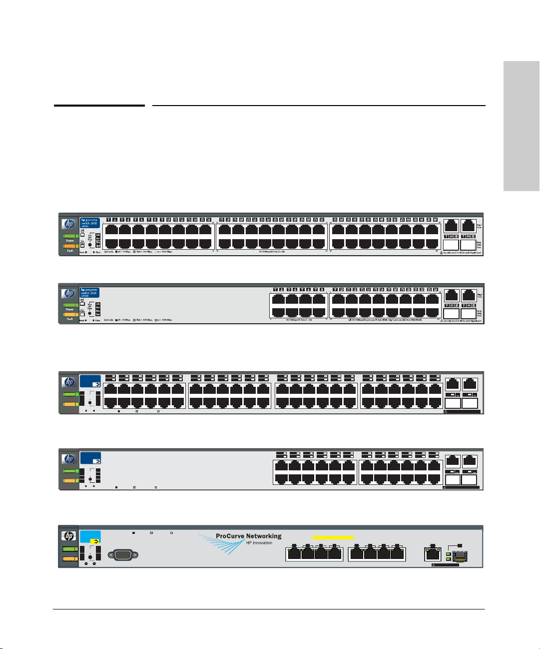
Throughout this manual, these switches will be referred to as the Series 2600
Switches and the Series 2600-PWR Switches.
1-1

Introducing the Switch
■ The Switch 2650 and 2650-PWR, has 48 auto-sensing 10/100Base-TX RJ-
45 ports with two dual-personality Gigabit Uplink ports.
■ The Switch 2626 and 2626-PWR, has 24 auto-sensing 10/100Base-TX RJ-
45 ports with two dual-personality Gigabit Uplink ports.
■ The Switch 2600-8-PWR, has 8 auto-sensing 10/100Base-TX RJ-45 ports
with one dual-personality Gigabit Uplink port.
The dual-personality ports are either auto-sensing 10/100/1000Base-T RJ-45,
Introducing the Switch
or mini-GBIC (Small Form Factor Pluggable (SFP) ports in an Ethernet
application).
The Series 2600-PWR Switches incorporate two additional features. These
switches offer two types of power, one for switch AC operating power, and
the other for Power over Ethernet (PoE) power:
■ Power-over-Ethernet or PoE power - PoE technology allows IP tele-
phones, wireless LAN Access Points and other appliances to receive
power as well as data over existing LAN cabling, without needing to
modify the existing Ethernet infrastructure. The Series 2600-PWR
Switches are designed with an internal PoE power supply capable of
providing 406 watts of PoE power (126 watts on the 2600-8-PWR). All of
the Switch 2600-PWR ports can provide up to 15.4 watts of PoE power to
connected devices. For further information regarding PoE power, see the
PoE Planning and Implementation Guide which is on the documentation
CD that came with the switch.
■ Redundant and External Power Supply Support - The Series 2600-
PWR Switches can be connected to a ProCurve 600 Redundant and
External Power Supply (J8168A), hereafter referred to as the 600 RPS/
EPS or a ProCurve 610 External Power Supply, hereafter referred to as
the 610 EPS, and receive redundant power from that unit. As an RPS unit,
the 600 RPS/EPS will provide all the AC power necessary to keep the
switch running should the switch internal AC power supply fail.
1-2
As an EPS unit, the 600 RPS/EPS and the 610 EPS can supply up to 408
watts of PoE power to the switch if the internal PoE power supply of the
switch should fail. When used with the Switch 2650-PWR, the additional
EPS power can provide up to 15.4 watts per port for 48 ports. For further
information regarding the 600 RPS/EPS or the 610 EPS PoE capabilities,
see the PoE Planning and Implementation Guide, which is on the
documentation CD that came with the switch.
With these switches you can directly connect computers, printers, and servers
to provide dedicated bandwidth to those devices, and you can build a switched
network infrastructure by connecting the switch to hubs, other switches, or
routers. In addition, the Series 2600 Switches offer full network management
capabilities.
Introducing the Switch
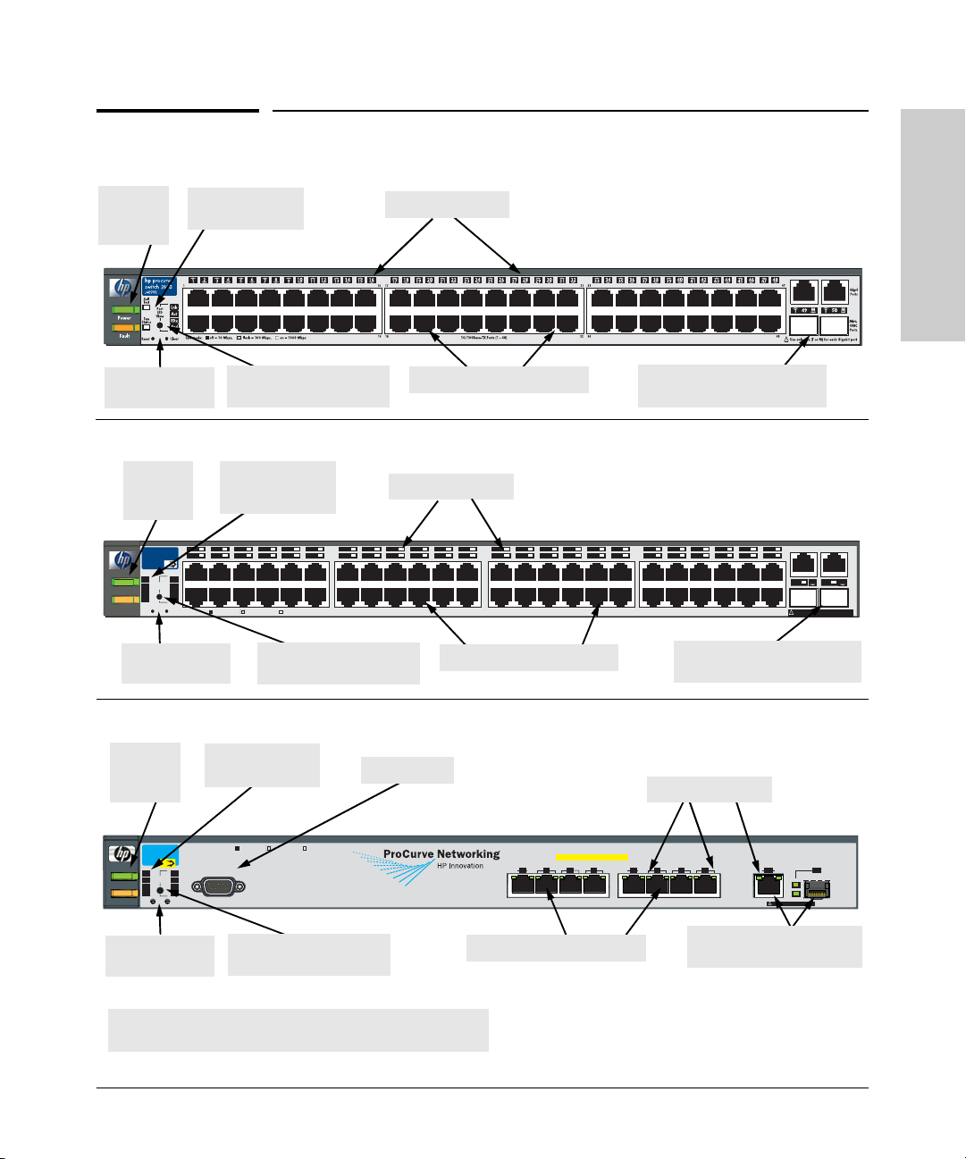
Front of the Switch
Power
and Fault
LEDs
Reset and Clear
buttons
Power
and Fault
LEDs
hp procurve
2650-PWR
switch
J8165A
PoE
Status
RPS
Act
LED
EPS
FDx
Mode
Power
Spd
Fan
Test
PoE
Fault
Reset
Clear
Reset and Clear
buttons
Front of the Switch
Self Test and Fan
Status LEDs
Port LED View select
button and indicator LEDs
RPS, EPS, Fan and
Test Status LEDs
1 3 5 7911
2 4 6 810
1
2
Spd mode: off = 10 Mbps,
flash = 100 Mbps, on = 1000 Mbps
LED Mode select button
15 17 19 21 23 25 27 29 31 33 35 37 39 41 43
13
12
14 16 18
11 23
13
12
14
PoE-Ready 10/100Base-TX Ports (1 - 48)
and indicator LEDs
Switch port LEDs
10/100Base-TX RJ-45 ports1
Switch port LEDs
20
Link|Mode
24
22
26
28 30 32 34 36 38 40 42 44
25
26
24
10/100Base-TX RJ-45 ports1
ProCurve Switch 2650
Dual-personality ports
(1000Base-T
2
or mini-GBIC)
ProCurve Switch 2650-PWR
474845
46
35 37
36
38
(all 10/100Base-TX ports are HP Auto-MDIX, Gig-T ports are IEEE Auto MDI/MDI-X)
Dual-personality ports
(1000Base-T
47
M
49
48
Use only one (T or M) for each Gigabit port
!
2
or mini-GBIC)
Introducing the Switch
Gig-T
Ports
M
50
MiniGBIC
Ports
Power
and Fault
RPS, EPS, Fan and
Test Status LEDs
Console Port
LEDs
ProCurve
Switch 2600-PWR
J8762A
PoE
Status
RPS
LED
EPS
Mode
Power
Fan
Test
Fault
Reset
Reset and Clear
buttons
1
All 10/100Base-TX RJ-45 ports have the HP Auto MDIX feature.
2
10/100/1000Base-T ports have the IEEE Auto MDI/MDI-X feature.
Spd mode: off = 10 Mbps, flash = 100 Mbps, on = 1000 Mbps
*
Act
FDx
Spd
*
PoE
Console
Clear
LED Mode select button
and indicator LEDs
Link Mode
1
PoE-Integrated 10/100-TX Ports (1 - 8)
2
Link
3
4
10/100Base-TX RJ-45 ports1
ProCurve Switch 2600-8-PWR
Switch port LEDs
Dual-Personality Port:
(Ports are HP Auto-MDIX)
Mode
5
6
8
7
(1000Base-T
10/100/1000-T (T) or Mini-GBIC (M)
(Port 9T is IEEE Auto MDI/MDIX)
Link
Mode
9M
9T
Link
Mode
Use only one (T or M) for Port 9
!
Dual-personality port
2
or mini-GBIC)
1-3

Introducing the Switch
Front of the Switch
Network Ports
■ 8, 24, or 48 auto-sensing 10/100Base-TX ports.
All these ports have the “HP Auto MDIX” feature, which means that you
can use either straight-through or crossover twisted-pair cables to
connect any network devices to the switch.
■ Dual-personality ports. You can use either the 10/100/1000Base-T RJ-45
connector, or install a supported ProCurve mini-GBIC for fiber-optic
Introducing the Switch
connections. The RJ-45 connectors support the IEEE Auto MDI/MDI-X
feature, which operates the same as the “HP Auto-MDIX” feature.
By default, the RJ-45 connectors are enabled. If a mini-GBIC is installed,
it is enabled and the associated RJ-45 connector is disabled and cannot
be used. If the mini-GBIC is removed, the associated RJ-45 port is
automatically re-enabled.
LEDs
On the Series 2600 Switches, there are three groupings of LEDs:
■ switch status LEDs (Table 1-1)
■ port LEDs (Table 1-2)
■ Port LED View (non-PWR switches) and LED Mode (PWR switches)
indicator LEDs (near the selector button) (Table 1-3)
1-4
Table 1-1. Switch Status LEDs
Switch LEDs State Meaning
Power
(green)
Fault
(orange)
On The switch is receiving power.
Off The switch is NOT receiving power. (Unless and RPS is connected to the
switch. If the switch looses power and the RPS is actively powering the
switch, the Power LED will be off and the switch will still have power and
all other LEDs will be functional.)
Off The normal state; indicates there are no fault conditions on the switch.
1
Blinking
On On briefly after the switch is powered on or reset, at the beginning of
A fault has occurred on the switch, one of the switch ports, the fan, or the
RPS or EPS operation of the switch. The Status LED for the component
with the fault will blink simultaneously.
switch self test. If this LED is on for a prolonged time, the switch has
encountered a fatal hardware failure, or has failed its self test. See
chapter 4, “Troubleshooting” for more information.

Introducing the Switch
Front of the Switch
Switch LEDs State Meaning
Self Test
(green)
labeled “Test”
on the PWR
switches
Off The normal operational state; the switch is not undergoing self test.
On The swit ch self test and initialization are in prog ress after you have power
cycled or reset the switch. The switch is not operational until this LED
goes off. The Self Test LED also comes on briefly when you “hot swap” a
mini-GBIC into the switch; the mini-GBIC is tested when it is h ot swapped.
1
Blinking
A component of the switch has failed its self test. The status LED for that
component, for example an RJ-45 port, and the switch Fault LED will blink
simultaneously.
Fan Status
(green)
On The cooling fan is operating normally.
1
Blinking
The cooling fan has failed. The switch Fault LED will be blinking
simultaneously.
RPS Status
(green)
2
On
Blinking
Normal operation. An 600 RPS/EPS unit is connected and operating
correctly. The 600 RPS/EPS could be powering the unit - see table below.
The 600 RPS/EPS is connected but may be powering another switch or
the 600 RPS/EPS has experienced a fault.
EPS Status
(green)
Off
2
On
Blinking
The 600 RPS/EPS is not connected or is not powered.
Connected to an External Power Supply, either an 600 RPS/EPS or an 610
EPS, and receiving PoE power.
The External Power Supply has experienced a fault:
• PoE power is oversubscribed (not enough PoE power available).
• The software on the ProCurve Series 2600-PWR Switches may not
support the EPS function.
• There is a fan, overcurrent, power supply, or temp fault.
• The Switch detect s the EPS is present but cannot c ommunicate with it.
Off
Check the Error Log on the switch for more information.
Introducing the Switch
The switch is not connected to an External Power Supply or the EPS cable
is connected but the External Power Supply is not powered up.
1
The blinking behavior is an on/off cycle once every 1.6 seconds, approximately.
2
ProCurve Series 2600-PWR Switches only.
See the ProCurve 600/610 External Power Supplies Installation and Getting
Started Guide for information on the LED behavior of the external power
supplies.
1-5

Introducing the Switch
Front of the Switch
Switch LEDs State Meaning
Switch 2626 and Switch 2650
Port LEDs
The port LEDs provide information about the individual switch ports.
Table 1-2. Port LEDs
Introducing the Switch
Port LEDs
(green – over-
laid with the
port number)
Displays port link information, network activity information, whether the port is
configured for full-duplex operation, or the speed of the connection depending on the
Port LED View selected. See “Port LED View Select Button and Indicator LEDs” on the
next page for more information.
Series 2600-PWR Switches
Link
(green - over-
laid with the
port number or
embedded
with the
connector)
On Indicates the port is enabled and receiving a link beat signal (for the
twisted-pair ports), of a strong enough light level (for the fiber-optic ports)
from the connected device.
Off
One of these condition exists:
• no active network cable is connected to the port
• the port is not receiving link beat or sufficient light
• the port has been disabled through the switch console, the web browser
interface, ProCurve Manager, or other network management tool.
1
Blinking
The port has failed self test. The switch Fault, and Self Test LEDs will flash
simultaneously.
Mode Depending on the mode selected, displays the following: network activity information,
whether the port is configured for Full Duplex operation, maximum speed operation, or
whether network errors are occurring on the port. See “LED Mode Select Button and
Indicator LEDs:” below for more information.
All Series 2600 Switches
T/M
(green)
2
On For the dual-personality ports, indicates the enabled port:
• if the “T” is on, the 10/100/1000Base-T RJ-45 port is enabled.
• if the “M” is on, the mini-GBIC port is enabled.
1
The blinking behavior is an on/off cycle once every 1.6 seconds, approximately.
2
For the 2600-8-PWR device, both connectors of the dual-personality port have Link and Mode LEDs. To
clearly indicate that the mini-GBIC/SFP port has taken control of port 9, when a mini-GBIC/SFP is fully
inserted into the garage, the Link LED will blink with a slow blink rate on the 9M port to indicate a status
change.
1-6
Introducing the Switch
0
Front of the Switch
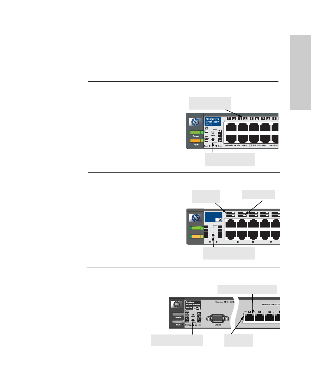
Multiple-Display Port LEDs - Port LED View or LED Mode Select Button and Indicator LEDs
To optimize the amount of information that can be displayed for each of the
switch ports in the limited space available, the Series 2600 Switches use
multiple-display LEDs for each port.
Switch 2626 and Switch 2650
For the non-PWR switches, there is a
single LED per port. The operation of
this LED is controlled by the Port LED
View select button, and the current
setting is indicated by the Port LED
View indicator LEDs near the button.
Press the button to step from one view
mode to the next. The default view is
Link (Lnk).
Port LED
(one for each port)
Port LED View select
button and indicator LED s
Introducing the Switch
For the PWR switches, there are two
LEDs per port. The Link status is
always shown by the Link LED. The
operation of the Mode LED is
controlled by the LED Mode select
button, and the current setting is indicated by the LED Mode indicator LEDs
near the button. Press the button to
step from one view mode to the next.
The default view is Activity (Act).
For the 2600-8-PWR switch,
the LEDs are embedded in
the port connector. The Link
and Mode LEDs operate the
same as the other PWR
switches (see above).
LED Mode select button
and indicator LEDs
Switch 2626-PWR and 2650-PWR
Link LED
(port number)
hp procurve
2650-PWR
switch
J8165A
PoE
Status
RPS
Act
LED
EPS
FDx
Fault
Mode
Spd
Fan
Test
PoE
Reset
Clear
Power
LED Mode select button
and indicator LEDs
1 3 5 79
2 4 6 810
1
2
Spd mode: off = 10 Mbps,
Mode LED
flash = 100 Mbps, on = 100
Switch 2600-8-PWR
Mode LED (Right LED)
Link LED
(Left LED)
1-7

Introducing the Switch
Front of the Switch
Switch LEDs State Meaning
Switch 2626 and Switch 2650
Table 1-3. Multiple-Display Port LEDs
Port LED View
indicator LEDs
(4 green LEDs)
Lnk
Indicates that the Port LEDs are displaying link information:
• if the Port LED is on, the port is enabled and receiving a link indication
from the connected device.
• if the Port LED is off, the port has no active network cable connected, or
Introducing the Switch
is not receiving signal or sufficient light. Otherwise, the port may have
been disabled through the switch console or the web browser interface.
• if the Port LED is blinking
1
simultaneously with the Fault LED, the
corresponding port has failed its self test.
Act
FDx
Spd
Indicates the Port LEDs are displaying network activity information.
Indicates the Port LEDs are lit for ports that are in full-duplex mode.
Indicates the Port LEDs are displaying the connection speed at which each
port is operating:
• if the Port LED is off, the port is operating at 10 Mbps.
• if the Port LED is flashing, the port is operating at 100 Mbps.
• if the Port LED is on continuously, the port is operating at 1000 Mbps.
Series 2600-PWR Switches
LED Mode
Act
Indicates the Port Mode LEDs are displaying network activity information.
indicator LEDs
(4 green LEDs)
FDx
Spd
Indicates the Port Mode LEDs are lit for ports that are in full-duplex mode.
Indicates the Port Mode LED s are displaying the connection sp eed at which
each port is operating:
• if the Port LED is off, the port is operating at 10 Mbps.
• if the Port LED is blinking
2
, the port is operating at 100 Mbps.
• if the Port LED is on continuously, the port is operating at 1000 Mbps.
PoE
Indicates the Port Mode LEDs are lit for ports that are providing PoE power
to the connected device.
1
The blinking behavior is an on/off cycle once every 1.6 seconds, approximately.
2
The blinking behavior is an on/off cycle once every 0.8 seconds, approximately.
1-8

Introducing the Switch
Front of the Switch
Reset Button
This button is used to reset the switch while it is powered on. This action clears
any temporary error conditions that may have occurred and executes the
switch self test.
Clear Button
This button is used for these purposes:
■ Deleting Passwords - When pressed by itself for at least one second, the
button deletes any switch console access passwords that you may have
configured. Use this feature if you have misplaced the password and need
console access.
This button is provided for your convenience, but its presence means that
if you are concerned with the security of the switch configuration and
operation, you should make sure the switch is installed in a secure
location, such as a locked wiring closet.
■ Restoring Factory Default Configuration - When pressed with the
Reset button in a specific pattern, any configuration changes you may
have made through the switch console, the web browser interface, and
SNMP management are removed, and the factory default configuration is
restored to the switch. For the specific method to restore the factory
default configuration, see “Restoring the Factory Default Configuration”
on page 11, “Troubleshooting” of this manual.
Introducing the Switch
1-9
Introducing the Switch
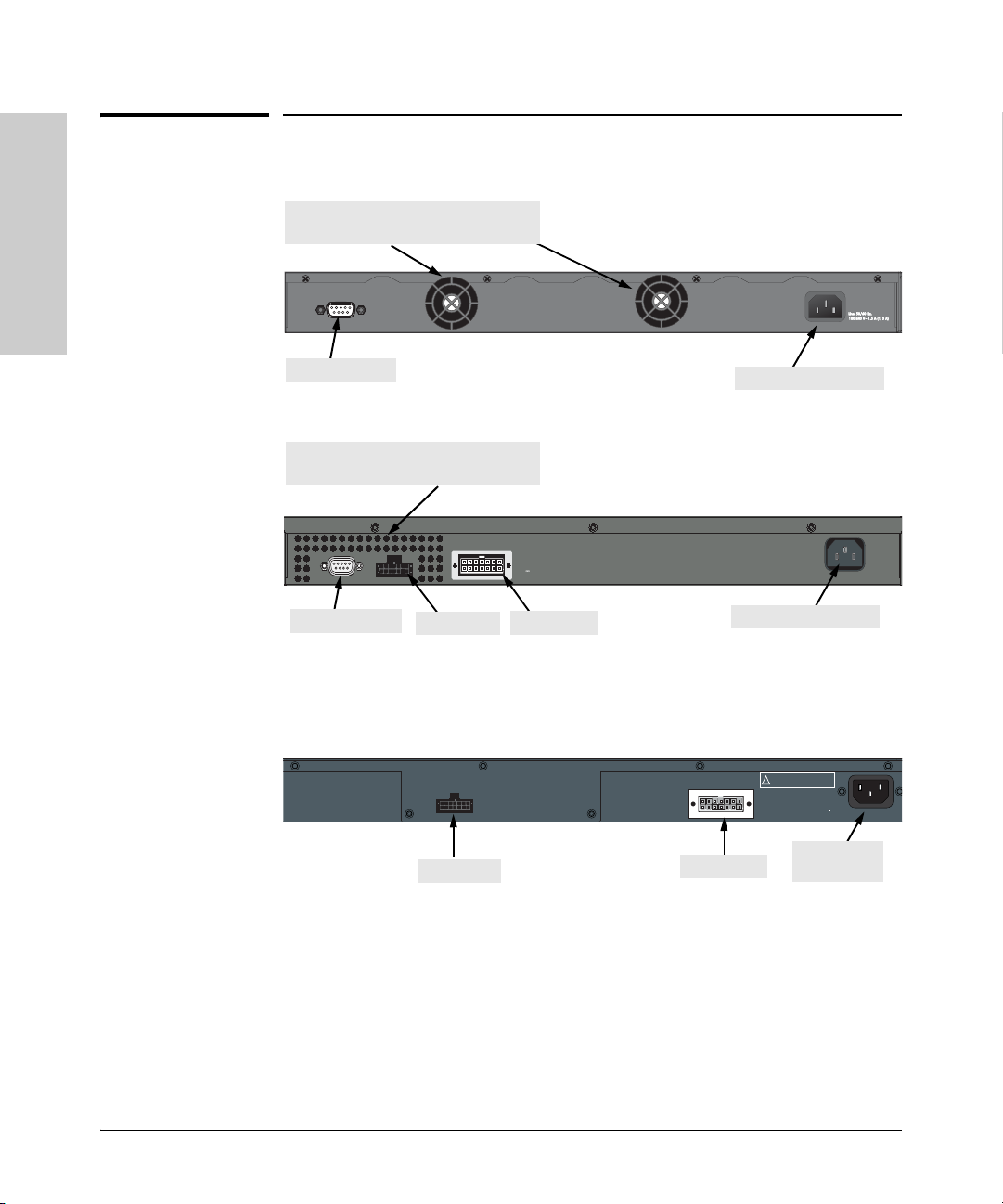
Back of the Switch
Back of the Switch
Cooling vent - make sure this is not
ProCurve Switch 2626 and 2650 non-PWR
obstructed for proper switch operation
Console
Introducing the Switch
Console Port
Cooling vent - make sure this is not
obstructed for proper switch operation
Console
EPS Input
Console Port
EPS Input RPS Input
HP ProCurve
RPS Input
12V 7.5A
ProCurve Switch 2626-PWR and 2650-PWR
AC power connector
Line 50/60 Hz.
100-240 V~ 7.5 A
AC power connector
ProCurve Switch 2600-8-PWR
1-10
EPS Input
ProCurve RPS InputEPS Redundant Input
RPS Input
Multiple power sources. Disconnect
both the AC power cord and the RPS cable
!
to completely remove power from the unit.
Line: 50/60 Hz
100 240 V~
3.3 A (3,3 A)
AC power
connector

Introducing the Switch
Switch Features
Console Port
This port is used to connect a console to a Series 2600 Switch by using the
serial cable supplied with each switch. This connection is described under
“8. (Optional) Connect a Console to the Switch” on page 30 in chapter 2,
“Installing the Series 2600 Switches.” The console can be a PC or workstation
running a VT-100 terminal emulator, or a VT-100 terminal.
Power Connector
The Series 2600 Switches do not have a power switch; they are powered on
when connected to an active AC power source. The switches automatically
adjust to any voltage between 100-240 volts and either 50 or 60 Hz. There are
no voltage range settings required.
Switch Features
The features of the Series 2600 Switches include:
■ 8, 24, or 48 auto-sensing 10/100Base-TX RJ-45 ports with HP Auto-MDIX.
■ dual-personality ports—either the auto sensing 10/100/1000Base-T RJ-45
or the mini-GBIC can be used for each port.
■ Power over Ethernet (PoE) operation—the 2600-PWR Series switches are
IEEE 802.3af compliant and provide up to 15.4W per port to power IP
phones, wireless access points, web cameras, and more. For more information, see the POE Planning and Implementation Guide, which is on
the Documentation CD-ROM that is included with your switch.
■ The 2600-8-PWR switch supports some pre-standard PoE devices, for a
current list see the FAQ page for the 2600-8-PWR Switch, which can be
found on the ProCurve Web site, http://www.procurve.com, Technical
Support, FAQs (all).
■ plug-and-play networking—all ports are enabled—just connect the
network cables to active network devices and your switched network is
operational.
■ HP Auto-MDIX on all 10/100 twisted-pair ports, and IEEE 802.3ab Auto
MDI/MDI-X on all 10/100/1000 twisted-pair ports, meaning that all
twisted-pair connections can be made using straight-through
cables. Cross-over cables are not required, although they will also work.
■ automatic learning of the network addresses in each switch’s 8000-
address forwarding table, (with configurable address aging value).
Introducing the Switch
1-11

Introducing the Switch
Switch Features
■ automatically negotiated full-duplex operation for the 10/100 and
10/100/1000 RJ-45 ports when connected to other auto-negotiating
devices—the mini-GBIC ports always operate at full duplex.
■ easy management of the switches through several available interfaces:
• console interface—a full featured, easy to use, VT-100 terminal
interface that is especially good for out-of-band switch management
or for Telnet access to the switch.
• web browser interface—an easy to use built-in graphical interface
Introducing the Switch
that can be accessed from common web browsers.
• ProCurve Manager—an SNMP-based, graphical network management tool that you can use to manage your entire network.
■ support for the Spanning Tree Protocol to eliminate network loops
■ support for up to 30 IEEE 802.1Q-compliant VLANs so you can divide the
attached end nodes into logical groupings that fit your business needs.
■ support for many advanced features to enhance network performance—
for a description, see the Management and Configuration Guide, which
is on the Documentation CD-ROM included with your switch.
■ download of new switch software for product enhancements or bug fixes.
1-12

Installing the Switch
The ProCurve Series 2600 Switches come with an accessory kit that includes
the brackets for mounting the switch in a standard 19-inch telco rack, in an
equipment cabinet, or on a wall. The brackets are designed to allow mounting
the switch in a variety of locations and orientations. Rubber feet are provided
that can be attached so the switch can be securely located on a horizontal
surface.
2
This chapter shows you how to install your Series 2600 Switches.
Included Parts
The Series 2600 Switches have the following components:
■ ProCurve Series 2600 Switches Installation and Getting Started Guide
(5991-2165), this manual
■ ProCurve Manager - CD ROM and booklet
■ Console cable
■ Customer Support/Warranty booklet
■ Accessory kits
Switches 2626 and 2650 Non-PWR
and Switch 2600-8-PWR
Kit number 5069-6535
Contains:
• two mounting brackets
• eight 8-mm M4 screws to attach the
mounting brackets to the switch
• four 5/8-inch number 12-24 screws to
attach the switch to a rack
• four rubber feet
1
The mounting brackets in this kit are longer to support the increased depth of the 2626-
PWR and 2650-PWR products.
Switches 2626-PWR and
2650-PWR
Kit number 5069-5705
Contains:
• two mounting brackets
• eight 8-mm M4 screws to attach the
mounting brackets to the switch
• four 5/8-inch number 12-24 screws to
attach the switch to a rack
• four rubber feet
1
Installing the Switch
2-1

Installing the Switch
Included Parts
■ AC power cord, one of the following:
Non-PWR Switches
and 2600-8-PWR
Australia/New Zealand
China
Continental Europe
Denmark
Japan
Switzerland
United Kingdom/Hong Kong/Singapore
United States/Canada/Mexico
South Africa
Thailand
Ta iw a n
1
The cords for the PWR Switches support a higher am perage, except for the 2600-8-PWR.
8120-6803
8120-8377
8120-6802
8120-6806
8120-6804
8120-6807
8120-8709
8120-6805
8120-8929
8121-0673
8121-0964
PWR Switches
8120-6810
8120-8471
8120-6811
8120-6814
8120-6804
8120-6815
8120-6809
8120-2371
8120-8929
8121-0673
8121-0964
1
Japan Power
Cord Warning
Installing the Switch
2-2

Installing the Switch
Installation Procedures
Installation Procedures
These steps summarize your switch installation. The rest of this chapter
provides details on these steps.
1. Prepare the installation site (page 2-5). Make sure the physical environment into which you will be installing the switch is properly prepared,
including having the correct network cabling ready to connect to the
switch and having an appropriate location for the switch. See page 2-4 for
some installation precautions.
2. Install mini-GBICs (optional—page 2-7). The switch has two slots for
installing mini-GBICs. Depending on where you install the switch, it may
be easier to install the mini-GBICs first. Mini-GBICs can be hot swapped—
they can be installed or removed while the switch is powered on.
3. Verify the switch passes self test (page 2-9). Plug the switch into a
power source and observe that the LEDs on the switch’s front panel
indicate correct switch operation.
4. Mount the switch (page 2-11). The Series 2600 Switches can be mounted
in a 19-inch telco rack, in an equipment cabinet, on a wall, or on a
horizontal surface. The Series 2600-PWR Switches may be mounted in
racks and cabinets or on a horizontal surface. The Switch 2626-PWR and
the 2650-PWR must not be wall mounted. The Switch 2600-8-PWR can be
wall mounted. See page 2-18 for wall mounting instructions.
5. Connect power to the switch (page 2-19). Once the switch is mounted,
plug it into the main power source.
6. Connect the network devices (page 2-20). Using the appropriate
network cables, connect the network devices to the switch ports.
7. Connect a 600 RPS/EPS or 610 EPS, (optional—page 2-21). You may
wish to use a 600 RPS/EPS or 610 EPS with your Series 2600-PWR Switch.
To do so you must connect these external power supplies using the RPS
or EPS cables supplied with these devices.
8. Connect a console to the switch (optional—page 2-30). You may wish
to modify the switch’s configuration, for example, to configure an IP
address so it can be managed using a web browser, from an SNMP network
management station, or through a Telnet session. Configuration changes
can be made by using the included console cable to connect a PC to the
switch’s console port.
Installing the Switch
At this point, your switch is fully installed. See the rest of this chapter if you
need more detailed information on any of these installation steps.
2-3

Installing the Switch
Installation Procedures
Installation Precautions
Follow these precautions when installing your ProCurve Series 2600 Switches.
WARNING ■ The rack or cabinet should be adequately secured to prevent it
from becoming unstable and/or falling over.
De vices i nstal led in a rack o r cabi net sho uld be m ounte d as lo w as
possible, with the heaviest devices at the bottom and progressively
lighter devices installed above.
■ For safe operation do not install the switch with the back of the
switch (with the fan vents) facing either downward or upward.
■ Do not wall mount the 2626-PWR or the 2650-PWR switches.
Cautions ■ Ensure the power source circuits are properly grounded, then use the
power cord supplied with the switch to connect it to the power source.
■ If your installation requires a different power cord than the one supplied
Installing the Switch
with the switch, ensure the cord is adequately sized for the switch’s
current requirements. In addition, be sure to use a power cord displaying
the mark of the safety agency that defines the regulations for power cords
in your country. The mark is your assurance that the power cord can be
used safely with the switch. If the PWR device’s supplied power cord does
not fit, contact HP.
2-4
■ When installing the switch, the AC outlet should be near the switch and
should be easily accessible in case the switch must be powered off.
■ Ensure the switch does not overload the power circuits, wiring, and over-
current protection. To determine the possibility of overloading the supply
circuits, add together the ampere ratings of all devices installed on the
same circuit as the switch and compare the total with the rating limit for
the circuit. Maximum ampere ratings are usually printed on the devices
near the AC power connectors.
■ Do not install the switch in an environment where the operating ambient
temperature might exceed 55 °C (131 °F), if using a 2600 switch, or 50 °C
(122 °F) if using a 2600-PWR switch.
■ Ensure the air flow around the sides and back of the switch is not
restricted. Leave at least 7.6 cm (3 inches) for cooling. If this unit is placed
in a fully-enclosed rack make certain the ambient temperature inside the
rack near the switch does not exceed 55 °C (if using a 2600 switch) or
50 °C (if using a 2600-PWR switch).

1. Prepare the Installation Site
■ Cabling Infrastructure - Ensure the cabling infrastructure meets the
necessary network specifications. See the following table for cable types
and lengths, and see appendix B, “Switch Ports and Network Cables” for
more information:
Table 2-1. Summary of Cable Types to Use With the Switch
Port Type Cable Type Length Limits
Twisted-Pair Cables
Installing the Switch
Installation Procedures
10/100/1000Base-T For either 10, 100 Mbps, or 1000 Mbps
operation:
Category 5 or better, 100-ohm UTP or shielded
twisted-pair (STP) balanced cable. For
1000 Mbps (gigabit) operation, Category 5e
cabling or better is recommended.
100 meters
Note: The Series 2600 Switches are
compatible with the IEEE 802.3ab standard
including the “Auto MDI/MDI-X” feature,
which allows use of either straight-through or
crossover twisted-pair cables for connecting
to any network devices including end nodes,
such as comput ers, or to other switch es, hubs,
and routers.
Note: For 1000 Mbps operation, all four wire
pairs are used for data transmission, therefore
PoE is not supported for 1000 Mbps operation.
Installing the Switch
2-5

Installing the Switch
Installation Procedures
Port Type Cable Type Length Limits
Fiber Optic Cables
Gigabit-SX
(on Gigabit-SX-LC
mini-GBIC)
Gigabit-LX
(on Gigabit-LX-LC
mini-GBIC)
Gigabit-LH
(on Gigabit-LH-LC
mini-GBIC)
Note:
Gigabit-LH - Between the transmit and receive ends of the cable, at least 5db of attenuation is required for a reliable
Installing the Switch
connection. This is equivalent to 20Km of the fiber-optic cable. For distances less than 20Km, you must add attenuators
to bring the total attenuation to at least 5db. Most cable vendors carry attenuators.
Multimode fiber-optic cables fitted with LC
connectors
Single-mode fiber-optic cables fitted with LC
connectors.
The multimode cables specified for the Gigab itSX mini-GBIC may also be used, but a modeconditioning patch cord may be neede d — see
“Mode Conditio ning Patch Cord for Gig abit-LX”
on page B-3 for more information.
The same single- mode fiber-optic cables as for
Gigabit-LX.
■ Installation Location - Before installing the switch, plan its location and
220 meters to 550 meters depending on the
cable used. See “Fiber-Optic Cables” on page
B-2 for more information.
• single-mode cable = 10 kilometers
• multimode cable = 550 meters
•70 kilometers
orientation relative to other devices and equipment:
• In the front of the switch, leave at least 7.6 cm (3 inches) of space for
the twisted-pair and fiber-optic cabling.
• In the back of the switch, leave at least 3.8 cm (1 1/2 inches) of space
for the power cord.
• On the sides of the switch, leave at least 7.6 cm (3 inches) for cooling.
2-6
Installing the Switch
48
47
46
4543
4442
41
40
39
38
37
Gig-T
Ports
MiniGBIC
Ports
47
48
50
49
T
M
T
M
Useonly one (T or M) for each Gigabit port
!
Installation Procedures
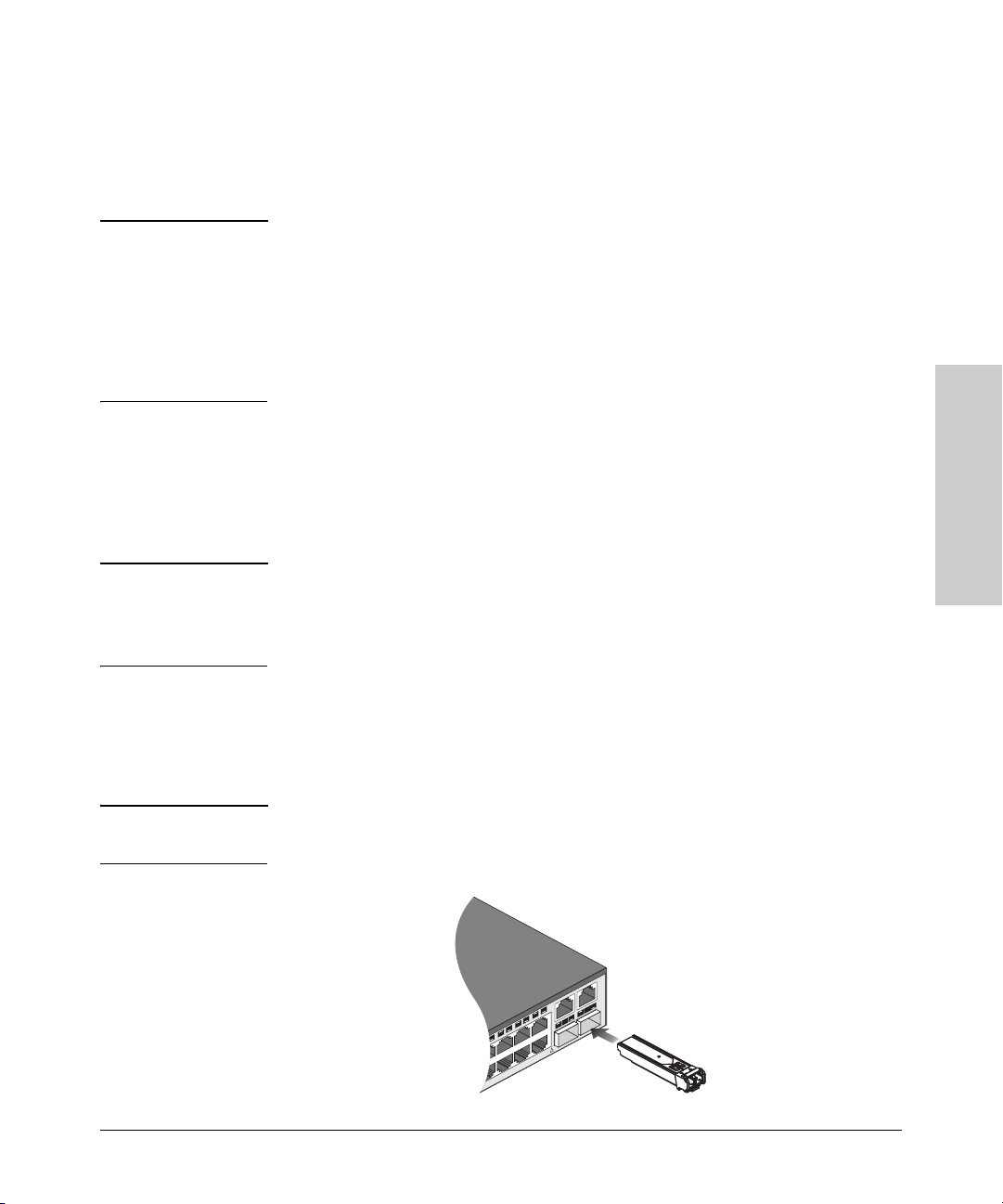
2. Installing or Removing mini-GBICs
You can install or remove a mini-GBIC from a mini-GBIC slot without having
to power off the switch. Use only ProCurve mini-GBICs.
Notes ■ The mini-GBIC slots are shared with the two 10/100/1000Base-T RJ-45
ports. If a mini-GBIC is installed in a slot, the associated RJ-45 port is
disabled and cannot be used.
■ The mini-GBIC ports operate only at full duplex. Half duplex operation is
not supported.
■ Ensure the network cable is NOT connected when you install or remove
a mini-GBIC.
When this manual was printed, the supported mini-GBICs include the
following:
■ ProCurve Gigabit-SX-LC mini-GBIC (J4858A and J4858B)
■ ProCurve Gigabit-LX-LC mini-GBIC (J4859A and J4859B)
■ ProCurve Gigabit-LH-LC mini-GBIC (J4860A and J4860B)
Caution Use only supported genuine ProCurve mini-GBICs with your switch. Non-
ProCurve mini-GBICs are not supported, and their use may result in product
malfunction. Should you require additional ProCurve mini-GBICs, contact
your ProCurve Networking Sales and Service Office or authorized dealer.
Installing the Switch
Installing the mini-GBICs:
Remove the protective plastic cover and retain it for later use. Hold the miniGBIC by its sides and gently insert it into either of the slots on the switch until
the mini-GBIC clicks into place.
WARNING The ProCurve mini-GBICs are Class 1 laser devices. Avoid direct eye
exposure to the beam coming from the transmit port.
2-7

Installing the Switch
Installation Procedures
Removing the mini-GBICs
Note You should disconnect the network cable from the mini-GBIC before removing
it from the switch.
Depending on when you purchased your ProCurve mini-GBIC, it may have
either of three different release mechanisms: a plastic tab on the bottom of
the mini-GBIC, a plastic collar around the mini-GBIC, or a wire bail.
To remove the mini-GBICs that have the plastic tab or plastic collar, push the
tab or collar toward the switch until you see the mini-GBIC release from the
switch (you can see it move outward slightly), and then pull it from the slot.
To remove the mini-GBICs that have the wire bail, lower the bail until it is
approximately horizontal, and then using the bail, pull the mini-GBIC from the
slot.
Replace the protective plastic cover on the mini-GBIC.
Installing the Switch
2-8
Installing the Switch
Installation Procedures
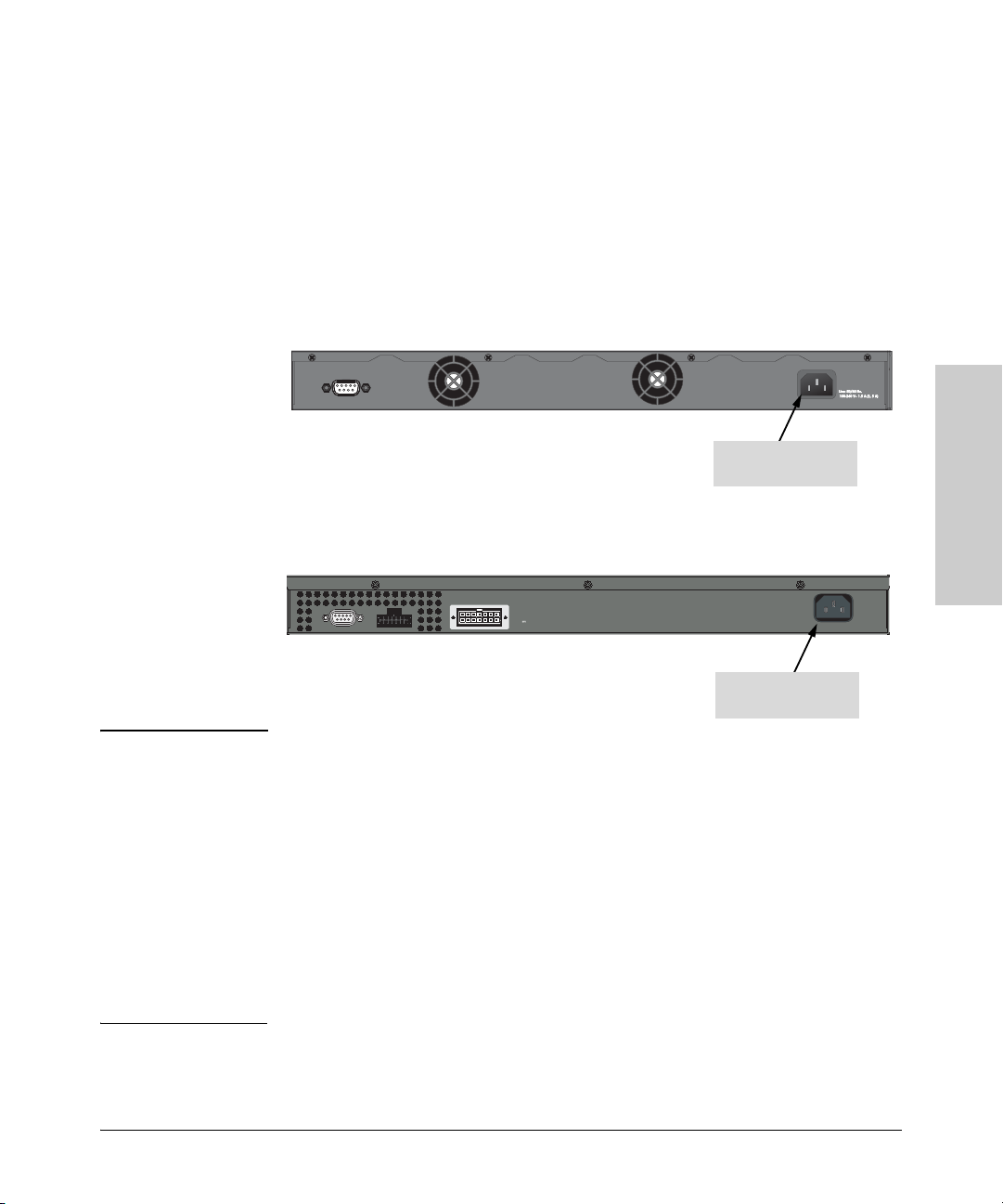
3. Verify the Switch Passes Self Test
Before mounting the switch in its network location, you should first verify it
is working properly by plugging it into a power source and verifying it passes
its self test.
1. Connect the power cord supplied with the switch to the power connector
on the back of the switch, and then into a properly grounded electrical
outlet.
2626 and 2650 non-PWR switches
Console
Connect power cord to
the power connector
2626 PWR and 2650 PWR switches
Installing the Switch
HP ProCurve
RPS Input
Console
EPS Input
12V 7.5A
Connect power cord to
Line 50/60 Hz.
100-240 V~ 7.5 A
the power connector
Note The Series 2600 Switches do not have a power switch. They are powered on
when the power cord is connected to the switch and to a power source. For
safety, the power outlet should be located near the switch installation.
The switch automatically adjusts to any voltage between 100-240 volts and
either 50 or 60 Hz. There are no voltage range settings required.
If your installation requires a different power cord than the one supplied with
the switch, be sure the cord is adequately sized for the switch’s current
requirements. In addition, be sure to use a power cord displaying the mark of
the safety agency that defines the regulations for power cords in your country.
The mark is your assurance that the power cord can be used safely with the
switch. If the PWR device’s supplied power cord does not fit, contact HP.
2-9
Installing the Switch
M
Installation Procedures
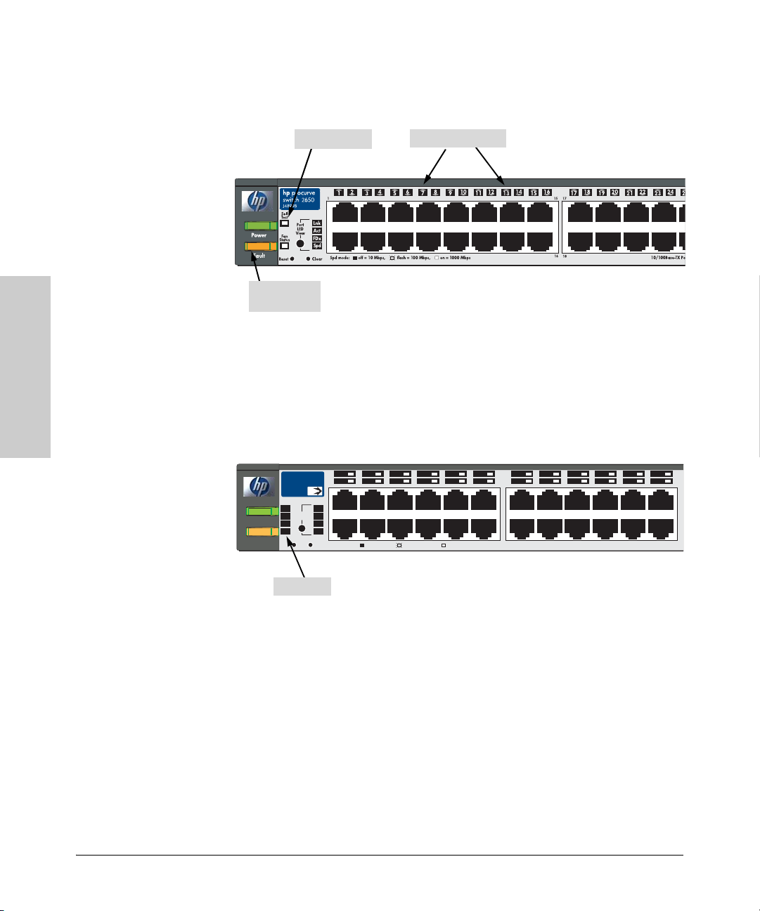
2. Check the LEDs on the switch as described below.
Self Test LED
Switch port LEDs
Switch 2650
Power and
Fault LEDs
When the switch is powered on, it performs its diagnostic self test. Self test
takes approximately 50 seconds to complete.
Switch 2650-PWR
Installing the Switch
Link|
24
24
Power
Fault
hp procurve
switch
J8165A
Status
RPS
EPS
Fan
Test
Reset
1 3 5 7911
2 4 6 810
2650-PWR
1
PoE
Act
LED
FDx
Mode
Spd
PoE
2
Spd mode: off = 10 Mbps,
Clear
flash = 100 Mbps, on = 1000 Mbps
12
14 16 18
11 23
13
12
14
PoE-Ready 10/100Base-TX Ports (1 - 48)
20
15 17 19 21 23
13
22
2-10
Test LED
LED Behavior
During the self test:
• Initially, all the switch and port LEDs are on. Most of the LEDs go off
and then may come on again during phases of the self test.
• For the duration of the self test, the Self Test LED stays on.
 Loading...