

HP ProCurve 745wl, ProCUrve Secure Access 700wl, ProCurve XL Installation And Getting Started Manual
Installation and
Getting Started Guide
ProCurve Secure Access 700wl Series
www.procurve.com


PROCURVE
SECURE ACCESS 700WL SERIES
INSTALLATION AND GETTING
STARTED GUIDE

© Copyright 2004, 2006 Hewlett-Packard Development
Company, L.P. The information contained herein is
subject to change without notice.
Publication Number
5991-4756
June, 2006
Edition 1
Applicable Products
ProCurve Access Control Server 745wl (J9038A)
ProCurve XL Access Controller Module (J8162A)
Trademark Credits
Windows NT®, Windows®, and MS Windows® are US
registered trademarks of Microsoft Corporation.
Disclaimer
The only warranties for HP products and services are set
forth in the express warranty statements accompanying such
products and services. Nothing herein should be construed
as constituting an additional warranty. HP shall not be liable
for technical or editorial errors or omissions contained
herein.
Warranty
See the Customer Support/Warranty booklet included with
the product.
A copy of the specific warranty terms applicable to your
Hewlett-Packard products and replacement parts can be
obtained from your HP Sales and Service Office or
authorized dealer.
ii

CONTENTS
Preface vii
Audience vii
Document Objectives vii
Organization vii
Related Publications ix
Document Conventions ix
Support Information ix
Compliance and Safety Notices ix
Chapter 1 Introduction to the ProCurve 700wl Series 1-1
Overview 1-1
Centralized Administration of the 700wl Series system 1-1
Order of Network Installation 1-2
Access Control Server with One or More Access Controller
Modules 1-2
Redundant Access Control Servers with One or More Access
Controller Modules 1-2
Tools and Information Required 1-3
Chapter 2 Hardware Installation 2-1
Hardware Description 2-1
System Memory/Storage 2-2
Chassis 2-2
Power Supply 2-2
Fans 2-2
I/O Ports 2-2
Controls and Indicators 2-3
Rear Chassis 2-4
Site Planning Checklist 2-4
Site Power Requirements and Heat Dissipation 2-5
Installing a 700wl Series System 2-6
Unpacking 2-6
iii

Rack Mounting the Chassis 2-6
Connecting Power to the Chassis 2-7
Chapter 3 Network Setup 3-1
Getting Started 3-1
Access Control Server Setup 3-2
IP Addressing Considerations 3-2
Initial Configuration Using the CLI 3-3
Initial Configuration Using the Administrative Console 3-8
Access Controller Module Setup 3-14
IP Addressing Considerations 3-14
Initial Configuration Using the CLI 3-15
Completing the Installation 3-15
Chapter 4 Basic Configuration 4-1
Procedure Overview 4-1
Preparation 4-2
Creating a User Account in the Built-In Database 4-2
User Authentication Through the Default Logon Page 4-3
PPTP Gateway Configuration 4-4
Configuring Access Policies for Encryption 4-5
PPTP Client Configuration 4-8
User Authentication Via PPTP Connection 4-11
External Authentication Service Configuration 4-11
Verify the External Authentication Service 4-15
Appendix A Troubleshooting A-1
Appendix B LCD Display Description B-1
Display Description B-1
Button Functionality B-1
Powering On and System Boot B-2
Default Display B-2
Main Menus B-2
System Shutdown B-3
Appendix C Technical Specifications, Safety and Compliance C-1
Technical Specifications C-1
Environmental Ranges C-1
iv Installation and Getting Started Guide

Power Requirements C-1
Physical Dimensions C-1
Safety and Regulatory Compliance C-2
Physical Interface C-2
Appendix D Cable and Connector Specifications D-1
Serial Console Port D-1
10/100 Downlink Ethernet Cables D-2
Power Crossover Connector D-2
Appendix E Safety and EMC Regulatory Statements E-1
Safety Information E-1
U.S.A. E-9
Canada E-9
Australia/New Zealand E-9
Japan E-9
Korea E-9
BSMI E-10
Regulatory Model Identification Number E-10
European Community E-11
Appendix F Recycle Statements F-1
Waste Electrical and Electronic Equipment (WEEE) Statements F-1
Index IX-1
Installation and Getting Started Guide v


PREFACE
This preface describes the objective, audience, use, and organization of the Installation and Getting Started
Guide. It also outlines the document conventions, related documentation, and support information.
Audience
The audience for this document is the network administrator who wants to enable network users to
communicate using the 700wl Series system. This document is intended for authorized personnel who
have previous experience working with network telecommunications systems or similar equipment. It is
assumed that the personnel using this document have the appropriate background and knowledge to
complete the procedures described in this document.
Document Objectives
This document contains procedural information describing the installation and configuration of the
ProCurve Access Control Server 745wl and XL Access Controller Module. Each procedure is written in a
task-oriented format consisting of numbered step-by-step instructions. In most cases, several procedures
are required to complete one overall task. All procedures should be performed in the order they appear in
this document, unless otherwise instructed.
This document also provides instructions for the creation of a basic configuration of the ProCurve Secure
Access 700wl Series that allows a user to:
• Connect to the 700wl Series system (optionally using the PPTP secure protocol)
• Log in and be authenticated through the ProCurve 700wl Series built-in database
• Pass IP traffic and have access to network resources.
A system running with this configuration is suitable for basic evaluation or demonstration purposes.
Organization
This document is organized as follows:
Chapter 1— Introduction
This chapter gives an overview of the 700wl Series system installation procedure.
vii

Chapter 2— Hardware Installation
This chapter describes the installation of the ProCurve Access Control Server 745wl. Installation of the XL
Access Controller Module is described in the ProCurve Series 5300xl Switches Installation and Getting Started
Guide.
Chapter 3— Network Setup
This chapter describes the network configuration of the Access Control Server after it has been physically
installed.
Chapter 4—Basic Configuration
This chapter leads you through the configuration of a basic system setup that includes user accounts and
user authentication, as well as a PPTP gateway, and support for an external authentication service. such
as LDAP.
Appendix A—Troubleshooting
This chapter presents troubleshooting procedures for the 700wl Series system.
Appendix B—LCD Display Description
This appendix describes the LCD display on the Access Control Server 745wl. The display can be used to
view the system’s network parameters, and to power down the system.
Appendix C—Technical Specifications, Safety and Compliance
This appendix describes the technical specifications of the system, and provides safety and compliance
information.
Appendix D—Cable and Connector Specifications
This appendix describes the Serial Connector and the Standard Ethernet cables for use with the 700wl Series
system.
Appendix E—Safety and EMC Regulatory Statements
This appendix describes safety and EMC regulatory information for the 700wl Series system.
Appendix F—Recycle Statements
This appendix describes Waste Electrical and Electronic Equipment (WEEE) information for the 700wl
Series system.
viii ProCurve Secure Access 700wl Series Installation and Getting Started Guide
Related Publications
The following publications provide additional information:
• ProCurve Secure Access 700wl Series Management and Configuration Guide
• ProCurve 700wl Series Release Notes
• ProCurve Series 5300xl Switches Installation and Getting Started Guide
Document Conventions
The following text conventions are used in this document:
Convention Definition
Boldface Arial Screen menus that you click to select, field names, and commands that
you select are in boldface Arial.
Italic Palatino New terms that are defined in the text, and emphasized terms are in italic
Palatino.
Courier Filenames and commands or text that you type are in Courier.
The following icons are used to alert you to important information:
Icon Notice Type Alerts you to...
None Note Helpful suggestions or information that is of special importance in
certain situations.
None Caution Risk of personal injury, loss of system functionality, or loss of data.
Warning Risk of severe personal injury, system damage, or irrecoverable
loss of data.
Support Information
See the ProCurve Networking web site at www.procurve.com. Click on technical support and select
support services for a list of available support resources and options for contacting HP.
Compliance and Safety Notices
Technical specifications, safety information, and regulatory compliance statements can be found in
Appendix C, “Technical Specifications”. This information should be read thoroughly before installing
the HP system equipment.
ProCurve Secure Access 700wl Series Installation and Getting Started Guide ix


INTRODUCTION TO THE PROCURVE
1
700WL SERIES
This chapter gives a brief description of the installation procedures for ProCurve 700wl Series products. It
consists of the following sections
Overview . . . . . . . . . . . . . . . . . . . . . . . . . . . . . . . . . . . . . . . . . . . . . . . . . . . . . . . . . . . . . . . . . . 1-1
Order of Network Installation . . . . . . . . . . . . . . . . . . . . . . . . . . . . . . . . . . . . . . . . . . . . . . . . . 1-2
Tools and Information Required . . . . . . . . . . . . . . . . . . . . . . . . . . . . . . . . . . . . . . . . . . . . . . . 1-3
Overview
Two products make up the ProCurve 700wl Series:
• ProCurve Access Control Server 745wl
• ProCurve XL Access Controller Module
The physical installation of the Access Control Server 745wl is described fully in Chapter 2, “Hardware
Installation”. The hardware installation is always performed first, before the network installation. The XL
Access Controller Module is installed in the 5300xl switches, and, therefore, its installation is described in
the ProCurve Series 5300xl Switches Installation and Getting Started Guide.
Centralized Administration of the 700wl Series system
Wireless network clients physically connect through Access Controller Modules, but authentication and
rights administration for these clients is handled centrally from the Access Control Server. In addition, all
configuration of the Access Controller Modules connected to the system is handled by the Administrative
Console located in the Access Control Server. Once you have installed an Access Controller Module onto
your network, you should not need to perform any administration functions directly on the Access
Controller Module.
From the centralized Administrative Console on your Access Control Server you can perform the
following configuration functions:
• Configure the 700wl Series system setup, including bridging, DHCP Network for NAT Clients,
Forwarding of IP Address broadcasts, setting up HTTP proxies, configuring SNMP settings, and
setting the system date & time
• Update the 700wl Series system software or return to a previous version
• Set up a Wireless Data Privacy policy for clients using VPN protocols
• Set up Authentication Policies for how users authenticate themselves to the system
• Set up Access Policies to control what users can do over the network
1-1

Introduction to the ProCurve 700wl Series
• Set up Identity Profiles to put users in groups that share the same access policies
• Set up Connection Profiles that allow you to specify different Access Policies for users based on
location, time of day, VLAN tags, and Authentication Policies
• Set up redundant Access Control Servers to provide failover
Additionally, the Administrative Console provides functions for monitoring the status of the system
components, as well as monitoring clients logged onto the system and their sessions.
Order of Network Installation
The order of installation depends on the complement of equipment you wish to install. There are two
basic configurations, and for each, there is an order of network installation as follows:
• Access Control Server 745wl with at least one XL Access Controller Module
• Two redundant Access Control Server 745wls with at least one XL Access Controller Module
Access Control Server with One or More Access Controller Modules
If you are installing one Access Control Server 745wl and one or more XL Access Controller Modules,
perform installation in the following order:
Step 1. Install the Access Control Server, following the steps in Chapter 2, “Hardware Installation” in this
manual.
Step 2. Perform the network setup for the Access Control Server, following the steps in “Access Control
Server Setup” on page 3-2.
Step 3. Install the Access Controller Modules following the steps in the ProCurve Series 5300xl Switches
Installation and Getting Started Guide.
Step 4. Once the Access Controller Modules are recognized by the Access Control Server and appear in
the Access Control Server Administrative Console, perform any additional setup required,
following the steps in“Completing the Installation” on page 3-15.
Redundant Access Control Servers with One or More Access Controller Modules
Step 1. Install each Access Control Server, following the steps in Chapter 2, “Hardware Installation” in
this manual.
Note: It is strongly recommended that an Access Control Server 745wl be used as the
secondary Access Control Server. If you use an Access Control Server 740wl as the redundant
Access Control Server, transferring the primary 745wl workload to a secondary 740wl may
result in the working integrity being compromised due to 740wl limitations.
Step 2. Perform the network setup for each Access Control Server, following the steps in“Access Control
Server Setup” on page 3-2.
1-2 ProCurve Secure Access 700wl Series Installation and Getting Started Guide

Introduction to the ProCurve 700wl Series
Note the IP address and shared secret of the Access Control Server that you plan to designate as
the Primary Access Control Server. Do not configure the Access Control Servers (yet) as
redundant peers.
Step 3. Install the Access Controller Modules following the steps in the ProCurve Series 5300xl Switches
Installation and Getting Started Guide.
Configure the Access Controller Modules with the IP address and shared secret of the Primary
Access Control Server.
Step 4. Once the Access Controller Module is recognized by the Primary Access Control Server and
appears in the Access Control Server Administrative Console, perform any additional setup
required, following the steps in “Completing the Installation” on page 3-15.
Step 5. On the Access Control Server that is to be the redundant (non-Primary) Access Control Server, set
the shared secret to be the same as the Primary Access Control Server.
Step 6. On the Primary Access Control Server, configure redundancy, following the steps in Chapter 6,
“Configuring the Network” in the ProCurve Secure Access 700wl Series Management and
Configuration Guide.
Tools and Information Required
To perform network installation for an Access Control Server or Access Controller Module, the
information defined in Table 1-1 may be required:
Note: The information you gather here is required during configuration and is presented here as a
reminder to find it before beginning the network installation.
Table 1-1. Installation Parameters
Parameter Form
Hostname (Fully-Qualified) Not required. Must be fully-qualified if provided.
Example: am21b.corp.com
Note: A hostname is required only for Access Control Servers that will have a
real Secure Socket Layer (SSL) certificate installed. If you install a signed SSL
certificate, the hostname must match that on the SSL certificate.
Domain name Defines the system’s domain if a hostname is not provided. This is optional.
Example: xyzcorp.com
IP address Can be configured as a static IP address or can be obtained via DHCP.
Note: The IP address of the Access Control Server will be needed to configure
Access Controller Modules.
Subnet Mask Defines the system’s subnet range. Can be obtained via DHCP. Example:
255.255.255.0.
Gateway (router) IP address Defines the default router. Can be obtained via DHCP.
Primary and Secondary DNS
server IP addresses
ProCurve Secure Access 700wl Series Installation and Getting Started Guide 1-3
Defines the location of the primary and backup DNS servers. Can be obtained
via DHCP.

Introduction to the ProCurve 700wl Series
Table 1-1. Installation Parameters
Parameter Form
Shared Secret Secret key used to establish trust relationship between an Access Control
Server and an Access Controller Module. Alphanumeric string. The same
shared secret must be configured on each system.
Many of these parameters can be supplied by the DHCP server if the system is configured to obtain its IP
address via DHCP. If the system is configured to use a static IP address, then all the parameters shown in
the table must be provided when the system is configured for the network.
The following tools and equipment are required to install a 700wl Series system in a rack:
• Tape measure and level
• Number 2 Phillips screwdriver
1-4 ProCurve Secure Access 700wl Series Installation and Getting Started Guide
HARDWARE INSTALLATION
This chapter describes the hardware installation of the ProCurve Access Control Server 745wl. (The XL
Access Controller Module is installed in the 5300xl switches, and, therefore, its installation is described in
the ProCurve Series 5300xl Switches Installation and Getting Started Guide.) You must be sure that the site
requirements are met and carefully follow the procedures described to physically install the equipment.
This chapter consists of the following sections:
Hardware Description . . . . . . . . . . . . . . . . . . . . . . . . . . . . . . . . . . . . . . . . . . . . . . . . . . . . . . . 2-1
Site Planning Checklist . . . . . . . . . . . . . . . . . . . . . . . . . . . . . . . . . . . . . . . . . . . . . . . . . . . . . . . 2-4
Installing a 700wl Series System . . . . . . . . . . . . . . . . . . . . . . . . . . . . . . . . . . . . . . . . . . . . . . . 2-6
2
Hardware Description
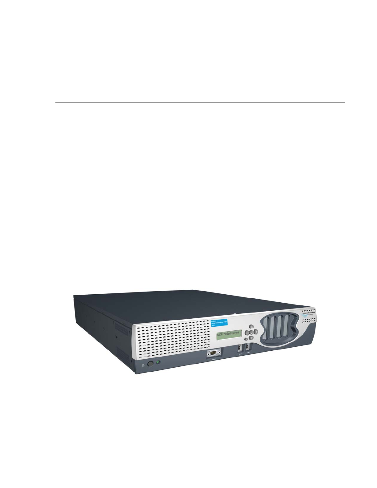
This section describes the hardware features of the Access Control Server 745wl, which is designed for
high-performance, high-density wiring-closet applications. Figure 2-1 shows an Access Control Server
745wl.
Figure 2-1. Access Control Server 745wl
The Access Control Server 745wl consists of a chassis, power supply, fans, I/O ports, indicators, and
switches. This unit has two RJ-45 connectors—one for the network uplink, used to connect the unit to the
network, and one that is used for the redundant Access Control Server.
2-1
Hardware Installation
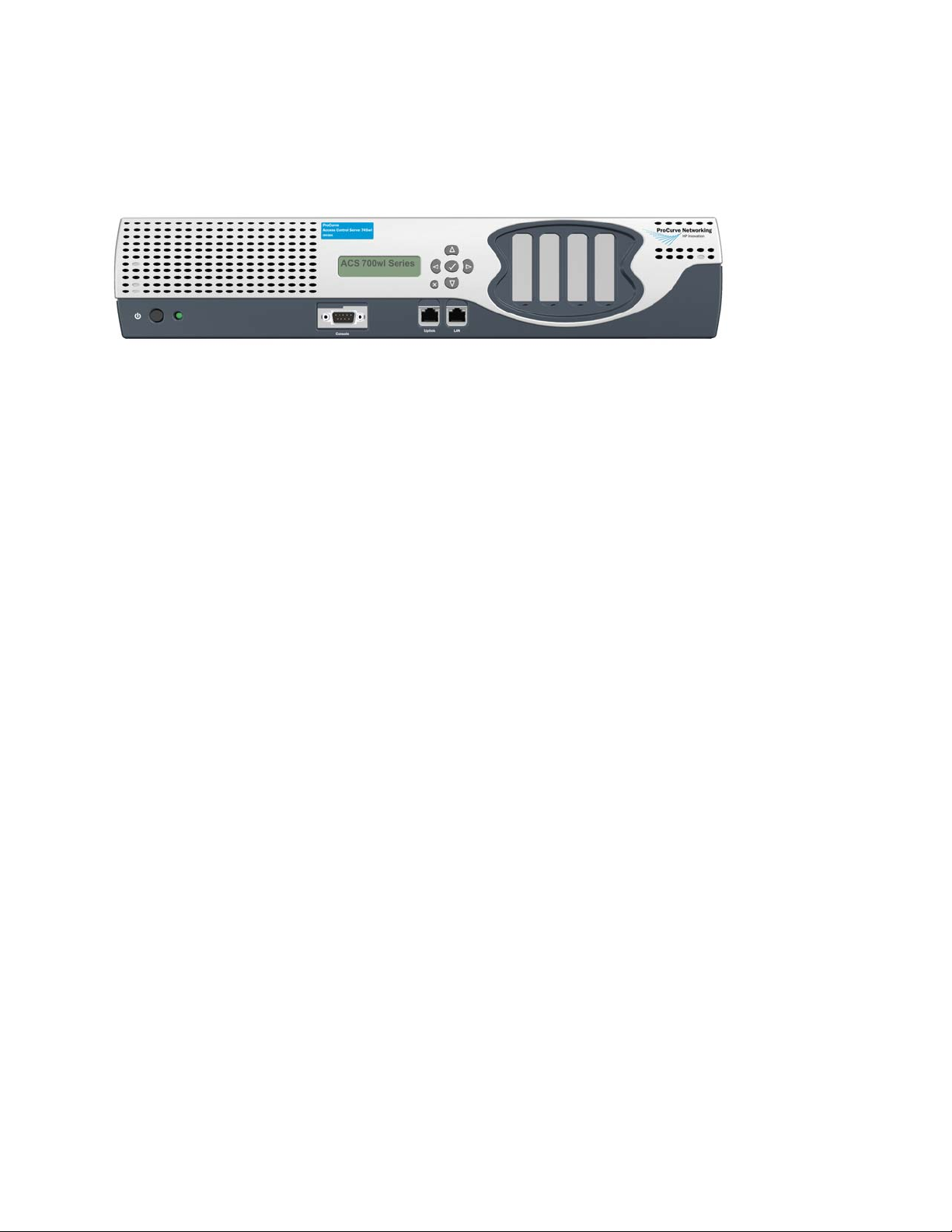
Figure 2-2 shows a front panel view of the Access Control Server 745wl.
Figure 2-2. Front panel view—Access Control Server 745wl
System Memory/Storage
The Access Control Server 745wl is equipped with a hard disk.
Chassis
The chassis is 17.00” (43.2 cm) wide, 22.00” (55.9 cm) deep, and 3.5” (8.9 cm) high, which is 2 rack units
(RU) high. It weighs approximately 35 lbs (15.9 kg). It can be rack-mounted using the front brackets
provided.
Power Supply
TheAccess Control Server 745wl contains an auto voltage sensing power supply. Input is 100-220 volts,
2.5A, 50/60 Hz, with a measured 350 watts output.
Fans
Note: For environmental specifications, see “Site Power Requirements and Heat Dissipation” on
page 2-5.
The system fan assembly provides cooling air for the internal chassis components. The fans exhaust warm
air from the back and draw in cool air at the front. The Access Control Server 745wl monitors its internal
fan speeds, internal chassis temperature, and power supply voltages. The status of these values are
reported by system software.
I/O Ports
Table 2-1 summarizes the functional I/O ports on the Access Control Server 745wl.
2-2 ProCurve Secure Access 700wl Series Installation and Getting Started Guide
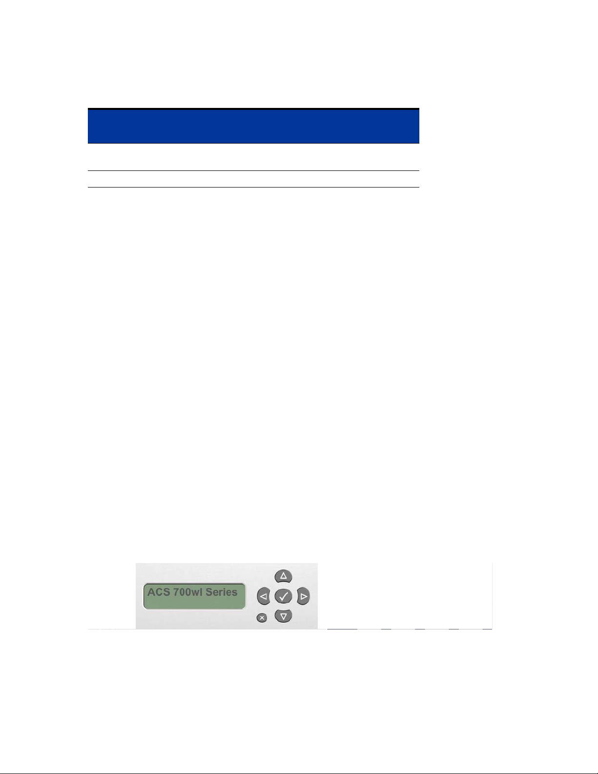
Table 2-1. I/O Ports
Port Function Description
Hardware Installation
Number
of Ports
Network Uplink RJ-45, 10Base-T/
100Base-TX/1000Base-T
Serial Console DB9, Serial Port 1
1
Controls and Indicators
Controls
There is only one control on the front of the chassis, a power button, labeled I/0. The power button is a
momentary switch and is used to turn on the system.
Note: The front panel power button should not be used to power off the system. Turning off the
system should be performed through software.
There is also a power supply switch on the rear of the Access Control Server 745wl, next to the power
cord socket. This switch must be left in the On (
used to power on the system. When this switch is in the Off (0) position, the front panel power button
will not function.
System Status Indicator
There is one system status LED indicator on the front of the chassis—Power (ON). ON is lit when the
power supply is plugged into a live outlet, the rear panel On/Off switch is in the On position, and the
power is turned on by the front panel On/Off button.
I) position for the unit to be operational, and cannot be
LCD Display
The LCD display can be used to view the system’s network parameters, and to power down the system.
The LCD display is located in the middle of the front panel of the Access Control Server 745wl. It is a 16character by two-line display, with six buttons located to the right of the display (Figure 2-3).
Figure 2-3. LCD Display
Appendix B, “LCD Display Description” describes the messages and operation of the LCD display panel.
ProCurve Secure Access 700wl Series Installation and Getting Started Guide 2-3
Hardware Installation
Network Uplink Status Indicators
A detailed view of the network interface (uplink port) is shown in Figure 2-4.
Figure 2-4. Network Uplink port
LED1 LED2
The two LEDs, LED1 and LED2, provide information on the port speed and data connection state of the
default network uplink port as shown in Table 2-2.
Table 2-2. Network uplink LED status
LED State LED1 (Port Speed) LED2 (Connection)
On Green: 10 Mbps, 1000 Mbps Link 100 Mbps, 1000 Mbps Link
Off 100 Mbps Link and Activity 10 Mbps Link and Activity
Blinking Green (Blink): 10 Mbps, 1000 Mbps Activity 100 Mbps, 1000 Mbps Link
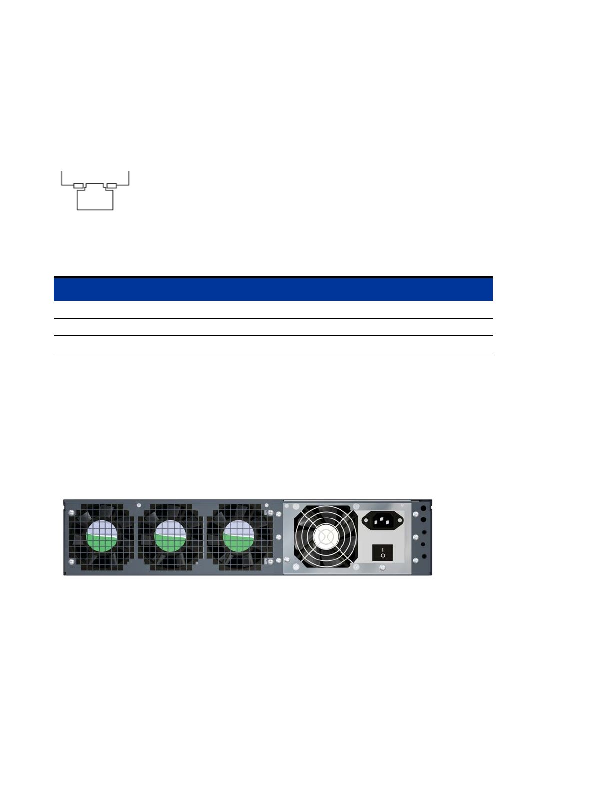
Rear Chassis
Figure 2-5 shows the rear of the Access Control Server 745wl. There is one control on the rear of the
chassis, a power switch. This switch cannot be used to power on the system. When this switch is in the
Off (0) position, the front panel power button will not function.
Note:
Figure 2-5. Rear chassis of an Access Control Server 745wl
The power switch must be left in the On (I) position for the unit to be operational.
Site Planning Checklist
Before installing an Access Control Server 745wl or XL Access Controller Module, you should evaluate
the items in the following site planning checklist:
Space Evaluation
•Space and layout
2-4 ProCurve Secure Access 700wl Series Installation and Getting Started Guide

• Floor covering
• Impact and vibration
• Lighting
• Maintenance access
Environmental Evaluation
• Ambient temperature
•Humidity
• Altitude
• Atmospheric contamination
•Airflow
Power Evaluation
•Input power type
• Proximity of receptacle to equipment
Hardware Installation
• UPS for power failures
Grounding Evaluation
• Circuit breaker size
Cable and Interface Equipment Evaluation
•Cable type
• Connector type
• Cable distance limitations
• Interface equipment (transceivers)
EMI Evaluation
• Distance limitations for signaling
•Site wiring
• RFI levels
Site Power Requirements and Heat Dissipation
Table 2-3 shows the site power requirements and heat dissipation for the Access Control Server 745wl.
ProCurve Secure Access 700wl Series Installation and Getting Started Guide 2-5

Hardware Installation
Table 2-3. Site Power Requirements, Temperature and Heat Dissipation Parameters
Parameter Value
AC Input Power (Watts) 170
Heat Dissipation (BTU/Hr.) 580
AC Input Current at 120 VAC (Amps) 1.4
AC Input Current at 240 VAC (Amps) .70
Operating Temperature Range, ×C 5 to +50
Storage Temperature Range, ×C -40 to +65
Humidity Range, non-condensing, percent 5 to 90
°
C
°
C
Installing a 700wl Series System
Unpacking
Carefully unpack the contents of the shipping containers, and save the containers and all packing
materials. To save storage space, you may want to flatten the containers. Check that the following is
included:
•Chassis
• Hardware and Accessories Kit
— 12-24 x 5/8 inch Phillips pan-head bolts, zinc (quantity: 4)
— 10-32 x 5/8 Phillips washer-head bolts, black (quantity: 4)
— Mounting Slide Kit
—U.S. power cord
— AT null modem cable (DB-9 female/DB-9 female)
• Documentation Kit
— Documentation CD-ROM
— Software License Agreement
— Software Release Notes
— ProCurve Secure Access 700wl Series Installation and Getting Started Guide (this document)
If any of the above are missing, contact HP immediately and do not attempt installation.
Rack Mounting the Chassis
Each Access Control Server 745wl comes with a steel mounting kit suitable for mounting the chassis in a
standard 19-inch (48.3 cm) equipment rack. Rack mounting instructions are included in the kit.
2-6 ProCurve Secure Access 700wl Series Installation and Getting Started Guide

Hardware Installation
Due to the weight of the unit, we highly recommend using these rails to mount the unit. This unit is not
suitable for mounting in racks with obstructions (such as a power strip) that could impair access to the
device. The air space in the front and rear of system should be 6.00 inches minimum.
Caution: Ground the chassis properly with the supplied power cord.
Caution: Be sure to position the power cord so that you can easily disconnect the chassis.
Caution: Do not install the chassis in an environment where the operating temperature might exceed
°
10
C (104°F).
Caution: Do not restrict air flow around the side and rear of the chassis. The air space in front and rear
of system should be 6.00 inches minimum.
Connecting Power to the Chassis
Follow these steps to connect power to the chassis:
Step 1. Before you connect the power supply to a power source, ensure that all site power and grounding
requirements listed in “Site Power Requirements, Temperature and Heat Dissipation
Parameters” on page 2-6 have been met.
Step 2. Plug the power cord into the rear of the chassis.
Step 3. Connect the other end of the power cord to an AC-power input source.
Caution: Ground the chassis properly with the supplied power cord.
Step 4. Be sure to position the power cord so that you can easily disconnect it from the chassis.
ProCurve Secure Access 700wl Series Installation and Getting Started Guide 2-7


NETWORK SETUP
This chapter describes the network setup of your 700wl Series system on an existing network to allow
interoperability and proper network security for all equipment.
It consists of the following sections:
Getting Started . . . . . . . . . . . . . . . . . . . . . . . . . . . . . . . . . . . . . . . . . . . . . . . . . . . . . . . . . . . . . . 3-1
Access Control Server Setup . . . . . . . . . . . . . . . . . . . . . . . . . . . . . . . . . . . . . . . . . . . . . . . . . . 3-2
Access Controller Module Setup . . . . . . . . . . . . . . . . . . . . . . . . . . . . . . . . . . . . . . . . . . . . . 3-14
3
Getting Started
The network configuration procedures in this chapter are performed after the hardware has been
installed. Access Control Server installation is described in Chapter 2, “Hardware Installation”, and
Access Controller Module installation is described in the ProCurve Series 5300xl Switches Installation and
Getting Started Guide. These network configuration procedures make a 700wl Series system (an Access
Control Server and associated Access Controller Modules) usable on your network.
The Access Control Server must always be installed before any Access Controller Modules are installed.
700wl Series system components are configured and managed centrally from the Administrative Console
that runs on the primary Access Control Server. Therefore, the initial network configuration includes only
the steps necessary to make the component accessible from the Access Control Server Administrative
Console.
• For an Access Control Server, you may be able to access the Administrative Console immediately upon
connecting the unit to your network, as the unit is configured by default to request an IP address using
the Dynamic Host Configuration Protocol (DHCP). If a DHCP server is reachable, and an address is
assigned to the ProCurve unit, you can point your browser to that IP address and access the
Administrative Console. You can determine the IP address by looking at the LCD panel on the front of
the unit.
If you want to assign a static IP address to the unit, you can connect a serial console to the unit’s
serial console port, and assign an IP address prior to connecting the unit to the network. Once you
have provided the necessary addressing information, you can connect to the Administrative
Console using a browser and complete the configuration.
• Management and configuration of an Access Controller Module is also performed from the centralized
Administrative Console on the Access Control Server. However, for the Access Control Server and the
Access Controller Module to communicate, the Access Controller Module must first be configured with
the IP address of the Access Control Server, and the shared secret used to validate the Access Controller
Module to its Access Control Server. Initial configuration is provided in the ProCurve Series 5300xl
Switches Installation and Getting Started Guide.
3-1

Network Setup
Access Control Server Setup
You can perform the initial network configuration of an Access Control Server in one of three ways:
• Connect a serial console to the Access Control Server’s serial console port and use the Command Line
Interface (CLI). See “Initial Configuration Using the CLI” on page 3-3 for detailed instructions.
• Connect the Access Control Server to your network, allowing it to get an IP address using the Dynamic
Host Configuration Protocol (DHCP). Then connect to its Administrative Console with a web browser.
See “Initial Configuration Using the Administrative Console” on page 3-8 for detailed instructions.
• Connect the Access Control Server to your network, allowing it to get an IP address using the
Dynamic Host Configuration Protocol (DHCP). Then open an SSH connection and log into the CLI.
The 700wl Series system supports SecureCRT 3.3 with the Auto Detect or Standard SSH server
options. See “Connecting Using SSH” on page 3-6 for detailed instructions.
Configuration beyond basic network installation, specifically the process of customizing the function of a
ProCurve 700wl Series system to a particular end-user environment, is not described in this manual.
Configuration performed after initial network installation is described in the ProCurve Secure Access 700wl
Series Management and Configuration Guide.
IP Addressing Considerations
An Access Control Server requires a stable IP address, so the Access Controller Modules under its control
can readily identify and communicate with the server. You can either arrange for DHCP to always assign
the same IP address to the Access Control Server, or you can manually enter a static IP address. Most
commonly, a static IP address is used.
A 700wl Series system ships configured by default to obtain its IP address and other information from a
Dynamic Host Configuration Protocol (DHCP) server. This means the system will attempt to obtain an IP
address as soon as it is connected to the network and is powered up.
Note: If you do not want the Access Control Server to attempt to use DHCP, you must configure its IP
address before you connect it to the network for the first time. You can configure the Access Control
Server without connecting it to the network using a serial console connected to the serial port.
If you elect to obtain the Access Control Server IP address using DHCP, the Access Control Server can
also obtain the hostname, domain name, subnet mask, and the IP addresses of the gateway, DNS servers,
WINS server, and NTP server from the DHCP server. The information it receives depends on how you
configured your DHCP server.
If you configure your DHCP server to assign the same IP address to the Access Control Server every time,
then even after a factory reset (which clears all configuration changes and returns the system to its default
settings) the Access Control Server will obtain the correct IP address upon a reboot. If you elect to use a
static IP address, you will need to reconfigure the address after a factory reset.
3-2 ProCurve Secure Access 700wl Series Installation and Getting Started Guide

Network Setup
To install an Access Control Server onto a network, you need the information shown in Table 3-1:
Table 3-1. Installation Parameters
Parameter Description
Access Control Server hostname
(optional)
Domain name (optional) Defines the Access Control Server’s domain if a
IP address This can be assigned as a static IP address or can be
Subnet mask (Netmask) Defines the Access Control Server’s subnet range. Can
Gateway (default router) IP address Defines the default router. Can be obtained via DHCP.
Primary and secondary DNS server IP
addresses
Access Control Server shared secret Secret key used to establish trust relationship with an
Must be fully-qualified if provided. Example:
am21b.corp.com
hostname is not provided. Example: corp.com
obtained via DHCP (the default).
be obtained via DHCP. Example: 255.255.255.0.
Defines the location of the primary and backup DNS
servers. Can be obtained via DHCP.
Access Controller Module. Alphanumeric string. The
same shared secret must be configured on the Access
Controller Module.
Initial Configuration Using the CLI
Note: If you want your system to receive its IP address via DHCP, and you do not plan to reconfigure
the uplink port, you can simply connect the unit to your network. By default a new unit requests an
address via DHCP. You can then follow the instructions in the section “Initial Configuration Using the
Administrative Console” on page 3-8.
The remainder of this section assumes you plan to assign a static IP address to the unit.
You can connect a serial console to the Access Control Server’s serial console port, and then configure the
Access Control Server’s network settings using the CLI.
You can use the CLI to perform both basic and advanced network configuration on an Access Control
Server. However, it is recommended that management and configuration normally be done through the
browser-based Administrative Console. Therefore, this section includes configuration of only those
parameters necessary to allow the Access Control Server to be recognized and communicate on the
network.
Note: See Appendix A in the ProCurve Secure Access 700wl Series Management and Configuration
Guide for full documentation of the commands available from the CLI.
Connecting a Serial Console
To use the CLI, you must first connect a null modem serial cable from the serial port male DB-9 connector
on the Access Control Server to a serial console. (Figure 3-1).
ProCurve Secure Access 700wl Series Installation and Getting Started Guide 3-3
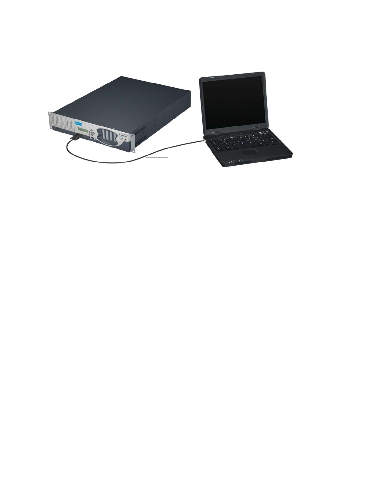
Network Setup
Figure 3-1. Connecting an Access Control Server to a Serial Console
External
Management
System
Serial Cable
Access Control Server 745wl
Use a craft terminal or a computer with a terminal emulation application to access the CLI. You will need
a serial cable with DB-9 female connectors on both ends to connect to the Access Control Server. A serial
crossover cable with DB-9 female connectors is included in the accessory kit shipped with the unit. See
Appendix D, “Cable and Connector Specifications” for the pinout specifications for this connector.
Configure the terminal session on your management computer as follows:
• Baud rate: 9600
• Data Bits: 8
• Stop bits: 1
• Flow Control: None
•Parity: None
Issuing Network Setup Commands from the Serial Console
After you have connected the serial console, follow these steps to configure the Access Control Server
network parameters. These instructions assume you have not connected the unit to the network.
Step 1. Power up the Access Control Server. You will see a series of messages on the terminal emulator
as the system boots and initializes itself.
At the end of the boot and initialization sequence you will see a prompt:
Serial Console
login:
Step 2. At the login prompt, enter admin as the login and then enter admin as the password.
login:admin
Password: xxxxx
The system then displays the command prompt:
HP ProCurve Access Control Server 700wl Series #<MAC address>
HP 700wl Series@[0.0.0.0]:
Step 3.
To configure the system with a static IP address, enter the following commands:
3-4 ProCurve Secure Access 700wl Series Installation and Getting Started Guide
 Loading...