

HP procurve radio port 220 Installation And Getting Started Manual
ProCurve Radio Port 220
Installation and
Getting Started Guide
www.procurve.com

© Copyright 2006 Hewlett-Packard Development Company, L.P.
The information contained herein is subject to change without
notice.
This document contains proprietary information, which is
protected by copyright. No part of this document may be
photocopied, reproduced, or translated into another
language without the prior written consent of HewlettPackard.
Publication Number 5991-3779
Applicable Products
ProCurve Radio Port 220 (J9005A)
Trademark Credits
Windows NT®, Windows®, and MS Windows® are US
registered trademarks of Microsoft Corporation.
Disclaimer
HEWLETT-PACKARD COMPANY MAKES NO WARRANTY
OF ANY KIND WITH REGARD TO THIS MATERIAL,
INCLUDING, BUT NOT LIMITED TO, THE IMPLIED
WARRANTIES OF MERCHANTABILITY AND FITNESS
FOR A PARTICULAR PURPOSE. Hewlett-Packard shall not
be liable for errors contained herein or for incidental or
consequential damages in connection with the furnishing,
performance, or use of this material.
The only warranties for HP products and services are set
forth in the express warranty statements accompanying
such products and services. Nothing herein should be
construed as constituting an additional warranty. HP shall
not be liable for technical or editorial errors or omissions
contained herein.
Hewlett-Packard assumes no responsibility for the use or
reliability of its software on equipment that is not furnished
by Hewlett-Packard.
Warranty
See the Customer Support/Warranty booklet included with
the product.
A copy of the specific warranty terms applicable to your
Hewlett-Packard products and replacement parts can be
obtained from your HP Sales and Service Office or
authorized dealer.

Introduction
Introduction
The ProCurve Radio Port 220, a component of the ProCurve Wireless LAN
System, links wireless 802.11a/b/g devices to the Ethernet network through a
wireless services-enabled switch. This device is to be used with the ProCurve
Switch 5300xl, with a ProCurve Wireless EDGE Services xl Module, or other
compatible wireless services-enabled switch product. These Radio Ports are
designed to be simple plug-and-play devices that require no individual device
configuration before being installed into a network. All Radio Port configuration, including country-specific settings, radio channel, radio power, SSID
settings, security settings, management information, and Radio Port firmware
is provided through the wireless services-enabled switch.
NOTE Before installing this Radio Port, a wireless services-enabled switch (such as
the ProCurve Switch 5300xl with Wireless EDGE Services xl Module installed)
should be deployed, configured, and operating in a Normal mode. See the
"ProCurve Wireless EDGE Services xl Module Getting Started Guide" for
details.
ProCurve Radio Port 220 Package Contents
ProCurve Radio Port 220 with external antenna connectors (Plenum Rated)
NOTE External Antennae must be purchased separately.
■ Two wall mount screws
■ Two wall anchors
■ Light pipe extender
■ Badge for light pipe extender
■ Label for badge
■ Radio Port Install Guide
■ Customer Support/Warranty booklet
Description
The ProCurve Radio Port 220 is a dual-radio IEEE 802.11-compliant device
supporting simultaneous 802.11a and 802.11b/g wireless Ethernet connections. The unit supports up to four external antennas, including up to two 2.4
GHz diversity antennas and up to two 5 GHz diversity antennas. Supported
Antennas are listed below under the section entitled Supported Antennas.
3
Introduction
The Radio Port 220 is designed for installation in either office or plenum
environments, using the mounting slots built into the underside of the metal
case. The Radio Port has one RJ-45 connector supporting 10/100 Ethernet and
requires power from any UL-listed, 802.3af-compatible Power over Ethernet
(PoE) switch or power injector.
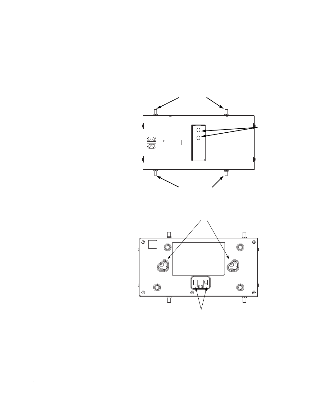
Top View
RSMA Antenna Connectors
2.4 Ghz Primary5 Ghz Primary
LEDs
2.4 Ghz Secondary5 Ghz Secondary
RSMA Antenna Connectors
Bottom View
Mount Slots
Light Pipe Clip Slots
4
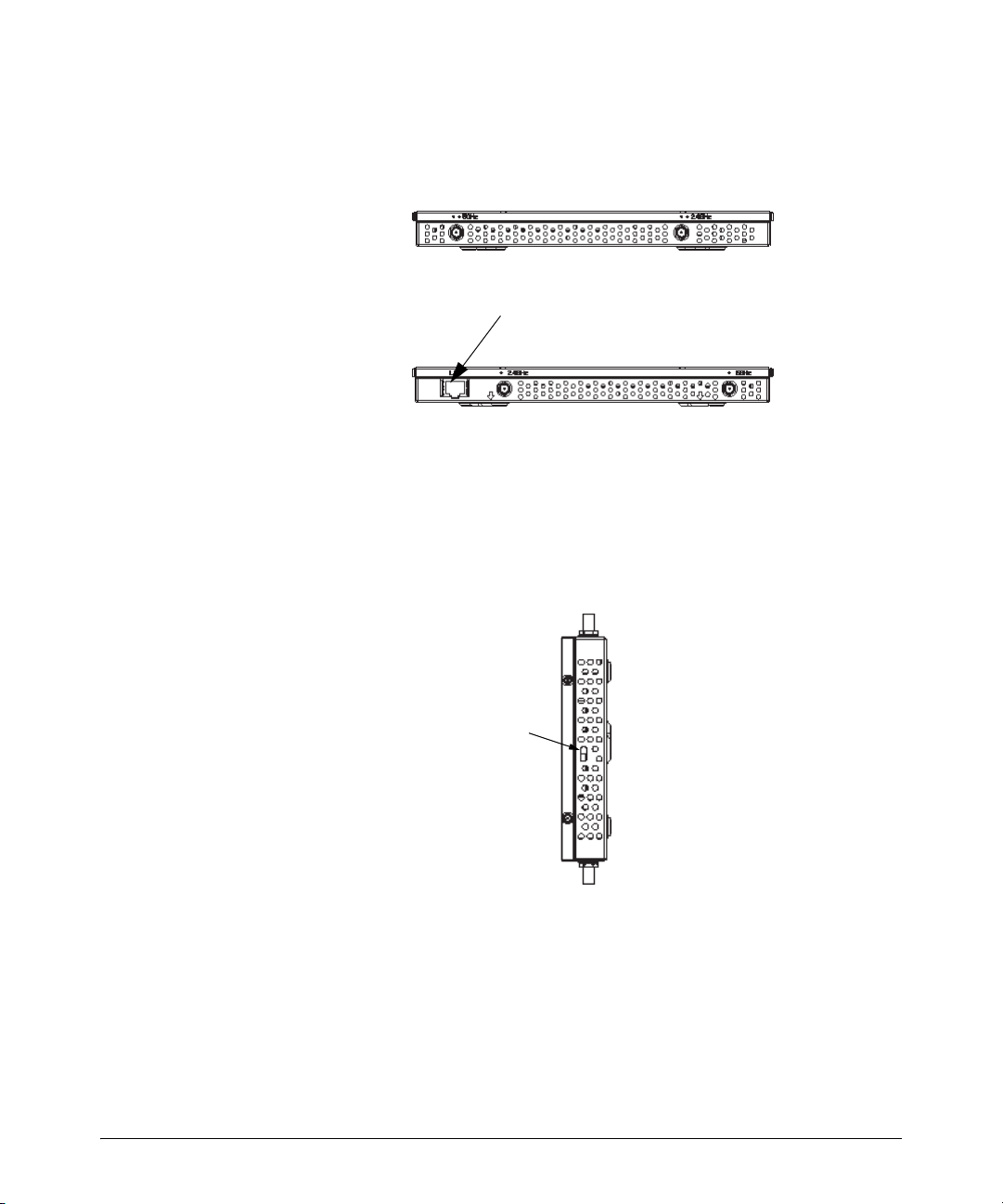
Front View
Introduction
Rear View
RJ-45
Lock Port
The lock port, compatible with laptop-style security cables, is on the side of
the case.
Lock Port
5

Introduction
Technical Specifications
Operating Voltage 48VDC (from 802.3af-compliant
Operating Current 148mA (typical)
Power 7W (typical)
Operating Temperature -4 to 122° F (-20 to 50° C)
Non-Operating/Storage
Temperature
Operating Humidity 5 to 95% (non-condensing)
Non-Operating/Storage
Humidity
Operating Altitude (max) 10,000 ft (3,048 m)
Non-Operating/Storage
Altitude
Plenum Rated UL 2043 - suitable for use in air
power source)
-40°F to 158°F (-40 to 70°C )
5 to 95% (non-condensing)
15,000ft.(4,572 m)
handling spaces
Dimensions & Weight
Length 237.2mm (9.34in.)
Width 139.6mm (5.50in.)
Height 25.4mm (1.0in.)
Weight 0.73kg (1.6lbs)
Features
■ High-performance 802.11-compliant radios
■ Two Reverse SMA (RSMA) connectors for 2.4-2.5Ghz antennas and two
Reverse SMA (RSMA) connectors for 4.9-5.825Ghz antenna connection
■ Supports a single antenna or dual antennas in diversity mode for both
802.11b/g (2.4 GHz) and 802.11a (5GHz) bands
■ Integrated 10/100 Base-TX Ethernet RJ-45 port
■ Two redundant sets of LED indicators, top and bottom of Radio Port
■ Lightpipe Extender for making LED indicators visible when Radio Port is
installed above a ceiling tile
■ Safety wire tie point (post)
■ Laptop-style lock port
■ Slots for wall mounting
6

Introduction
Radio Characteristics
The ProCurve Radio Port 220 contains two IEEE 802.11-compliant radios: (1)
an 802.11b/g radio operating in the 2.4 to 2.5 GHz band and (2) an 802.11a radio
operating in the 4.9 to 5.875Ghz band. The Radio Port accepts a broad range
of 2.4-2.5GHz and 4.9-5.875GHz external antennas that can be connected to
the Radio Port's two pairs of R-SMA antenna connectors. The following table
lists the 802.11-compliant operating modes for each radio. The three supported 802.11g operating modes are simultaneous CCK and OFDM, CCK only,
or OFDM only.
Device Mbps Data Rate Support Utilizing
802.11a 6, 9, 12, 18, 24, 36, 48, 54
OFDM
802.11b/g 1, 2, 5.5, 11 CCK
6, 9, 12, 18, 24, 36, 48, 54
OFDM
Diversity
Transmit and
receive
Transmit and
receive
GHz
4.9 to 5.875
range
2.4 to 2.5 ISM
range
Integrated RJ-45 Port
The ProCurve Radio Port 220 has one RJ-45 connector supporting a full-duplex
10/100Base-TX Ethernet port and requires IEEE 802.3af-compliant Powerover-Ethernet (PoE) from an external source such as a Power-over-Ethernet
(PoE) switch or power injector. Installers can use of a single CAT-5 cable to
supply both Ethernet connectivity and power to the Radio Port, allowing these
Radio Ports to be installed up to 100 m (300 ft.) from a PoE-compliant 10/100
Ethernet port. There is no additional power supply required.
LED Indicators
The Radio Port 220 has LED indicators on the front of the case that visually
display the status of the device. When the Radio Port is mounted above a
suspended ceiling, an additional set of LED indicators on the back of the unit
can be extended through the ceiling tile using a provided lightpipe extender,
making the Radio Port location and status visible from below the ceiling.
7
Introduction
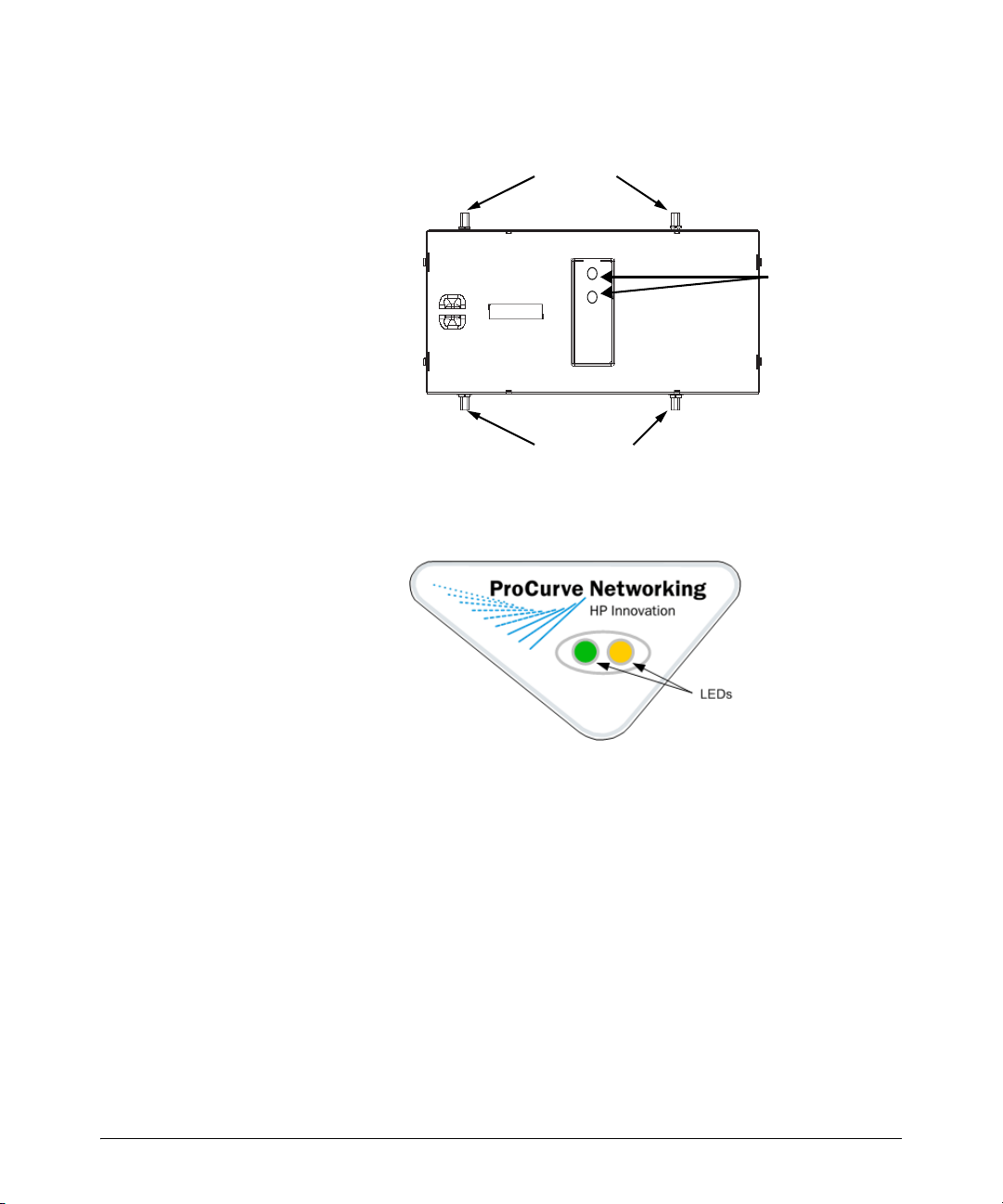
Wall Mount.
Top View
RSMA Antenna Connectors
2.4 Ghz Primary5 Ghz Primary
LEDs
2.4 Ghz Secondary5 Ghz Secondary
RSMA Antenna Connectors
Above Ceiling Mount.
The LED indicators display connection status and error conditions, as well as
network activity for each of the two radios. Operation is as follows:
Start-up:
Radio Port Startup occurs immediately following the application of PoE
power, or following a power or software reset.
1. Both GREEN and AMBER LEDs light steadily for several seconds while
the Radio Port performs an internal self-test.
2. The AMBER LED then flashes 3 times per second, while the GREEN LED
is off. This indicates that the Radio Port is attempting to communicate to
a compatible wireless services-enabled switch.
3. Both LEDs then go off for a moment, followed by both LEDs lighting
steadily for a few seconds.
8

Installation Instructions
4. After this sequence, assuming no error conditions have occurred, the
Radio Port will enter Normal operation mode. This means that the Radio
Port has successfully communicated with and been adopted by a wireless
services-enabled switch. If this startup sequence repeats itself, then it is
likely that the Radio Port is unable to contact a compatible wireless
services -enabled switch, and the installer should review the Troubleshooting section below.
Normal Operation:
Once the Radio Port has established a connection to a compatible wireless
services-enabled switch the Radio Port will begin normal operation. During
normal operation, the GREEN LED indicates status of the 802.11 b/g radio,
and the AMBER LED indicates status of the 802.11a radio.
■ Without Wireless Traffic: Each LED will briefly flash once every 5 seconds,
to indicate that power is on, and the Radio Port is communicating normally to its wireless services-enabled switch. The flashing may not be
synchronous between the two LED indicators.
■ With Wireless Traffic: Each LED will briefly flash more frequently than
once every 5 seconds, and in an irregular fashion, to represent traffic on
that radio.
Radio Error Mode:
■ The GREEN LED flashes on and off steadily once per second if an error
prevents the 802.11b/g radio from operating normally.
■ The AMBER LED flashes on and off steadily once per second if an error
prevents the 802.11a radio from operating normally.
Installation Instructions
The ProCurve Radio Port 220 can be mounted either on a wall or other
mounting point, or above a suspended ceiling. This Radio Port is not designed
for mounting on a desk.
To prepare for installation, perform the following steps:
1. Review site survey and network analysis reports to determine the location
and mounting position for the ProCurve Radio Port 220. Verify the
recommended external antenna type and antenna mounting configuration.
2. Match the Radio Port model number on the purchase order with the model
numbers in the packing list and on the case of the device shipped.
9

Installation Instructions
3. Verify that the contents of the box include the intended ProCurve Radio
Port 220 and mounting hardware:
Radio Port Item Notes
220 J9005A 802.11a & 802.11b/g radios with external connectors.
This radio port is configurated with two pairs of
RSMA connectors
4. Verify that you have the recommended external antenna model and type
for the desired installation. External antennas must be purchased separately. For a list of Supported Antennas for this Radio Port, see 'Supported
Antennas' below.
5. Connect a CAT-5 cable to a compatible 802.3af power source and run the
cable to the installation site. Ensure that there is sufficient slack on the
cable to perform the installation steps.
10
 Loading...