

HP ProCurve MSM765zl Installation And Getting Started Manual

ProCurve MSM765zl Mobility Controller
Installation and Getting Started Guide
MSM765-IGSG-5992-5964.book Page 1 Thursday, April 2, 2009 6:48 PM
MSM765-IGSG-5992-5964.book Page 2 Thursday, April 2, 2009 6:48 PM
MSM765-IGSG-5992-5964.book Page i Thursday, April 2, 2009 6:48 PM
HP ProCurve MSM765zl
Mobility Controller
Installation and Getting Started Guide
MSM765-IGSG-5992-5964.book Page ii Thursday, April 2, 2009 6:48 PM
© Copyright 2009 Hewlett-Packard Development Company, L.P.
Publication Number
5992-5964
April 2009
Applicable Products
HP ProCurve MSM765zl Mobility Controller J9370A
HP ProCurve Switch 5406zl J8697A
HP ProCurve Switch 5406zl-48G J8699A
HP ProCurve Switch 5412zl J8698A
HP ProCurve Switch 5412zl-96G J8700A
HP ProCurve Switch 8212zl J8715A
Software Credits and Notices
SSL on HP ProCurve Switches is based on the OpenSSL
software toolkit. This product includes software developed
by the OpenSSL Project for use in the OpenSSL Toolkit. For
more information on OpenSSL, visit www.openssl.org.
Hewlett-Packard assumes no responsibility for the use or
reliability of its software on equipment that is not furnished
by Hewlett-Packard.
Warranty
See the Customer Support/Warranty booklet included with
the product.
A copy of the specific warranty terms applicable to your
Hewlett-Packard products and replacement parts can be
obtained from your HP Sales and Service Office or
Safety
Before installing and operating these products, please read
the “Installation Precautions” in chapter 1, and the safety
statements in Appendix A, “EMC Regulatory Statements”.
Web Version of this Document
The printed version of this document that was shipped with
the HP ProCurve MSM765zl contains the latest information
at time of printing. To view or download the latest version of
this document and other documentation, visit:
www.procurve.com/customercare/support/manuals/index.htm.
Disclaimer
HEWLETT-PACKARD COMPANY MAKES NO WARRANTY
OF ANY KIND WITH REGARD TO THIS MATERIAL,
INCLUDING, BUT NOT LIMITED TO, THE IMPLIED
WARRANTIES OF MERCHANTABILITY AND FITNESS
FOR A PARTICULAR PURPOSE. Hewlett-Packard shall not
be liable for errors contained herein or for incidental or
consequential damages in connection with the furnishing,
performance, or use of this material.
The information contained herein is subject to change
without notice. The only warranties for HP products and
services are set forth in the express warranty statements
accompanying such products and services. Nothing herein
should be construed as constituting an additional warranty.
HP shall not be liable for technical or editorial errors or
omissions contained herein.
Hewlett-Packard Company
8000 Foothills Boulevard, m/s 5552
Roseville, California 95747-5552
http://www.procurve.com
MSM765-IGSG-5992-5964.book Page 1 Thursday, April 2, 2009 6:48 PM
Contents
1 Hardware Installation
MSM765zl Overview . . . . . . . . . . . . . . . . . . . . . . . . . . . . . . . . . . . . . . . . . . . . . 1-1
Installing the MSM765zl . . . . . . . . . . . . . . . . . . . . . . . . . . . . . . . . . . . . . . . . . . 1-2
Installation Precautions . . . . . . . . . . . . . . . . . . . . . . . . . . . . . . . . . . . . . . 1-2
Installation Procedure . . . . . . . . . . . . . . . . . . . . . . . . . . . . . . . . . . . . . . . 1-2
Verifying the MSM765zl is Installed Correctly . . . . . . . . . . . . . . . . . . . . 1-4
Environmental Specifications . . . . . . . . . . . . . . . . . . . . . . . . . . . . . . . . . . . . . 1-5
2 Getting Started
Overview . . . . . . . . . . . . . . . . . . . . . . . . . . . . . . . . . . . . . . . . . . . . . . . . . . . . . . 2-1
Connect to the Switch . . . . . . . . . . . . . . . . . . . . . . . . . . . . . . . . . . . . . . . . . . . 2-1
Verify Switch Software Version . . . . . . . . . . . . . . . . . . . . . . . . . . . . . . . . 2-2
Activate the MSM765zl . . . . . . . . . . . . . . . . . . . . . . . . . . . . . . . . . . . . . . . . . . . 2-3
Obtain the Activation Hardware ID . . . . . . . . . . . . . . . . . . . . . . . . . . . . 2-3
Register the MSM765zl . . . . . . . . . . . . . . . . . . . . . . . . . . . . . . . . . . . . . . . 2-4
Install the Product License Key . . . . . . . . . . . . . . . . . . . . . . . . . . . . . . . . 2-5
Configure the Switch for the MSM765zl . . . . . . . . . . . . . . . . . . . . . . . . . . . . 2-5
About MSM765zl Ports . . . . . . . . . . . . . . . . . . . . . . . . . . . . . . . . . . . . . . . 2-6
Initial MSM765zl Configuration . . . . . . . . . . . . . . . . . . . . . . . . . . . . . . . . . . 2-10
Determine Switch Index of the MSM765zl . . . . . . . . . . . . . . . . . . . . . . 2-10
Assign an IP Address to the MSM765zl LAN Port . . . . . . . . . . . . . . . . 2-11
Configure the MSM765zl Internet Port . . . . . . . . . . . . . . . . . . . . . . . . . 2-11
Additional Documentation . . . . . . . . . . . . . . . . . . . . . . . . . . . . . . . . . . . 2-15
Restarting and Resetting the MSM765zl . . . . . . . . . . . . . . . . . . . . . . . . . . . 2-15
Restarting the MSM765zl . . . . . . . . . . . . . . . . . . . . . . . . . . . . . . . . . . . . 2-15
Resetting an MSM765zl to Factory Defaults . . . . . . . . . . . . . . . . . . . . 2-16
3 Troubleshooting
HP Customer Support Services . . . . . . . . . . . . . . . . . . . . . . . . . . . . . . . . . . . 3-1
1

MSM765-IGSG-5992-5964.book Page 2 Thursday, April 2, 2009 6:48 PM
A EMC Regulatory Statements
U.S.A. - FCC Class A . . . . . . . . . . . . . . . . . . . . . . . . . . . . . . . . . . . . . . . . A-1
Canada . . . . . . . . . . . . . . . . . . . . . . . . . . . . . . . . . . . . . . . . . . . . . . . . . . . A-1
Australia/New Zealand . . . . . . . . . . . . . . . . . . . . . . . . . . . . . . . . . . . . . . A-1
Japan - VCCI Class A . . . . . . . . . . . . . . . . . . . . . . . . . . . . . . . . . . . . . . . . A-2
Korea . . . . . . . . . . . . . . . . . . . . . . . . . . . . . . . . . . . . . . . . . . . . . . . . . . . . . A-2
Taiwan . . . . . . . . . . . . . . . . . . . . . . . . . . . . . . . . . . . . . . . . . . . . . . . . . . . A-2
B Waste Electrical and Electronic Equipment (WEEE)
Statements
C Hardware Components
Front Panel Port and LEDs . . . . . . . . . . . . . . . . . . . . . . . . . . . . . . . . . . . . . . C-1
Serial Numbers . . . . . . . . . . . . . . . . . . . . . . . . . . . . . . . . . . . . . . . . . . . . . . . . C-2
Switch LEDs . . . . . . . . . . . . . . . . . . . . . . . . . . . . . . . . . . . . . . . . . . . . . . . . . . C-4
Replacing or Removing an MSM765zl . . . . . . . . . . . . . . . . . . . . . . . . . . . . . C-4
Replacing the Disk Drive . . . . . . . . . . . . . . . . . . . . . . . . . . . . . . . . . . . . . . . . C-5
Replacing the Flash Card . . . . . . . . . . . . . . . . . . . . . . . . . . . . . . . . . . . . . . . . C-6
Index
2
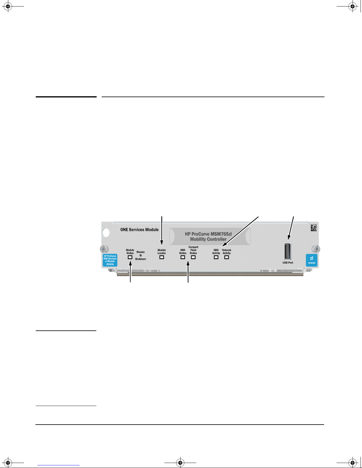
MSM765zl Locator LED
HDD and CF Status LEDs
HDD and Network
activity LEDs
USB port
Module Status LED
MSM765-IGSG-5992-5964.book Page 1 Thursday, April 2, 2009 6:48 PM
Hardware Installation
MSM765zl Overview
The HP ProCurve Networking MSM765zl Mobility Controller is a Services zl
Module-based WLAN controller. It plugs in to either the 5400zl or 8212zl
switches. The MSM765zl Mobility Controller is referred to in this document
as the MSM765zl. New switches need to be prepared according to their
supplied documentation.
A maximum of four MSM765zls can be installed in the same chassis. Under
certain conditions, a maximum of three MSM765zls are supported in the 5406zl
chassis. See “Environmental Specifications” on page 1-5.
1
Figure 1. Front panel of the MSM765zl
See also “Front Panel Port and LEDs” on page C-1.
Note This manual contains the basic information needed to get you started using
the MSM765zl. It also contains EMC Regulatory Statements (Appendix A) and
Waste Electrical and Electronic Equipment (WEEE) Statements (Appendix
B). Appendix C provides hardware component information.
For more information on working with the MSM765zl, see the MSM7xx
Controllers Management and Configuration Guide. The latest version of this
and all HP ProCurve Networking documentation is available at:
www.procurve.com/customercare/support/manuals/index.htm.
1-1
MSM765-IGSG-5992-5964.book Page 2 Thursday, April 2, 2009 6:48 PM
Hardware Installation
Installing the MSM765zl
Installing the MSM765zl
Installation Precautions
■ Static electricity can severely damage the electronic components on the
MSM765zl. When handling and installing the MSM765zl, follow these
procedures to avoid damage from static electricity:
• Handle the MSM765zl by its bulkhead or edges and avoid touching
the components and the circuitry on the board.
• When installing the MSM765zl, equalize any static charge difference
between your body and the switch by wearing a grounding wrist
strap and attaching it to the switch’s metal body, or by frequently
touching the switch’s metal body.
■ The MSM765zl has “low-force”, high-performance connectors. High
insertion forces are not necessary to install the MSM765zl, and should
not be used.
■ Ensure the MSM765zl is fully inserted. Press the MSM765zl into the
slot until the bulkhead on the MSM765zl contacts or is very close to
contacting the front face of the switch chassis.
■ Once the MSM765zl is fully inserted, screw in the two retaining screws
to secure the MSM765zl in place.
■ For safe operation, proper switch cooling, and reduction of electromag-
netic emissions, ensure that a slot cover is installed on any unused
MSM765zl slot. For safety, no more than one slot should be uncovered
at a time when the switch is powered on.
■ Respect the temperature specifications for the MSM765zl.
To install the MSM765zl into a switch, the switch can be powered on or off.
The following procedure assumes the switch is powered on.
Installation Procedure
1. Use a Torx T-10 or flat-bladed screwdriver to unscrew the screws in the
cover plate over the slot where the MSM765zl is to be installed. Remove
the cover, and store the cover plate for possible future use.
2. Hold the MSM765zl by its bulkhead—taking care not to touch the metal
connectors or components on the board.
3. Open the extractor handles.
1-2
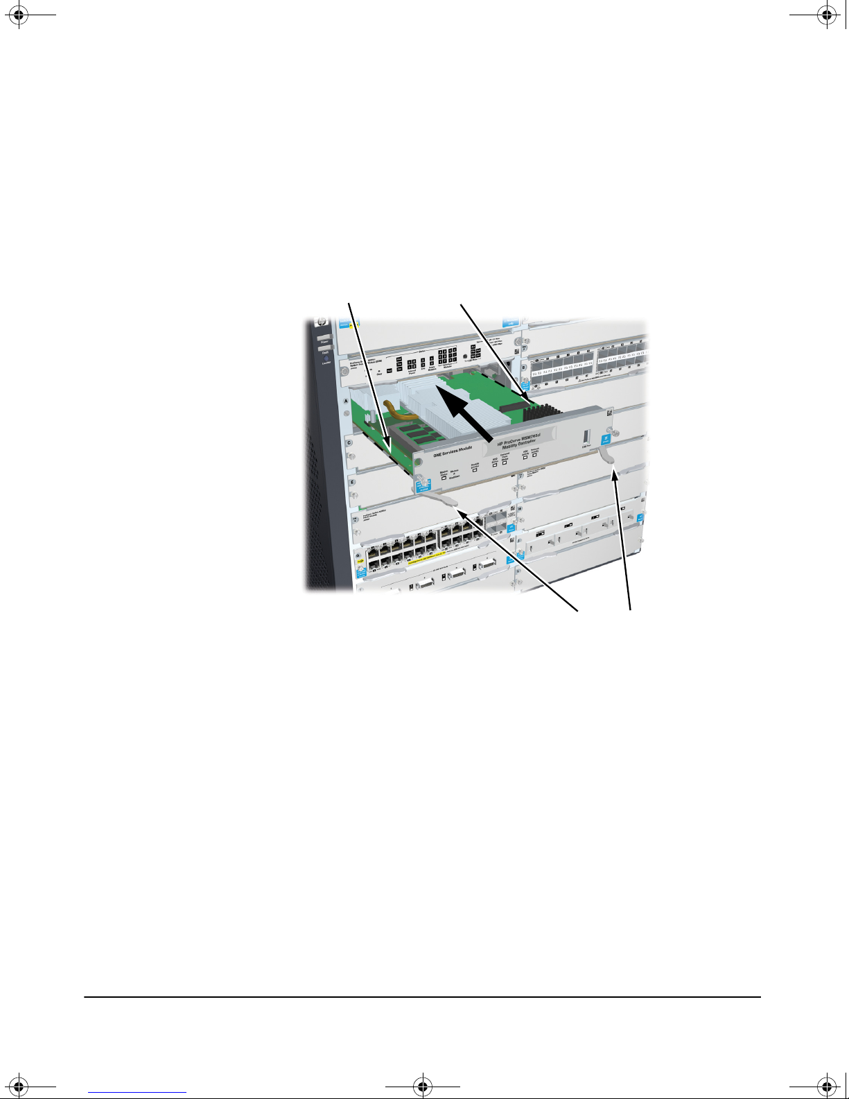
Insert MSM765zl into the guides and slide in until fully
inserted.
Open extractor handles
MSM765-IGSG-5992-5964.book Page 3 Thursday, April 2, 2009 6:48 PM
4. Insert the MSM765zl aligning with the guides in the slot, and slide it into
the slot until it is fully inserted.
5. Once the contacts have engaged, use the extractor handles to seat the
MSM765zl completely.
6. Tighten the screws.
Hardware Installation
Installing the MSM765zl
Figure 2. MSM765zl being installed
1-3
MSM765-IGSG-5992-5964.book Page 4 Thursday, April 2, 2009 6:48 PM
Hardware Installation
Installing the MSM765zl
Verifying the MSM765zl is Installed Correctly
When the MSM765zl is installed properly, it undergoes a self test that takes a
few seconds. This happens both when the switch is powered on after installing
the MSM765zl, and when the MSM765zl is installed while the switch already
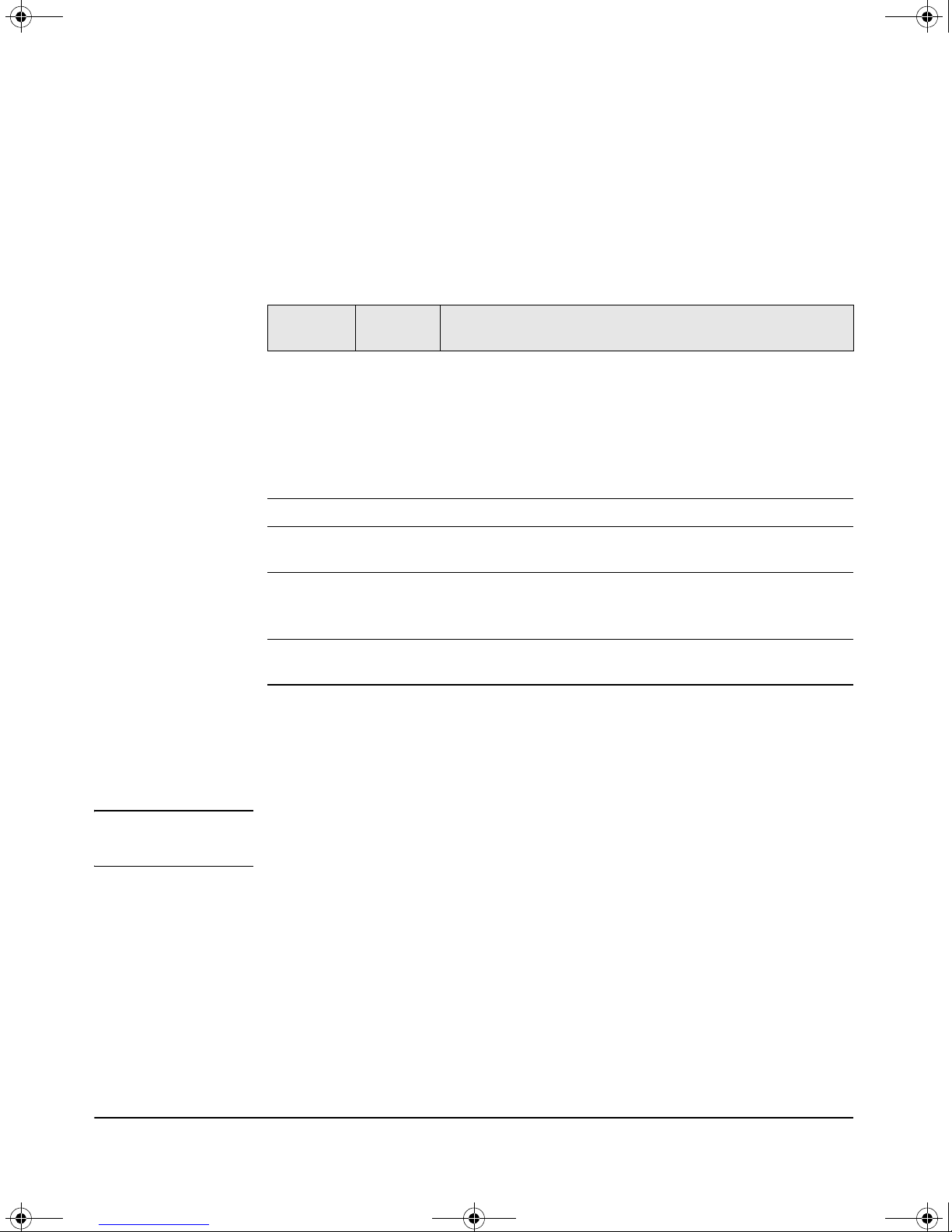
has power. The LEDs help determine if the MSM765zl has passed the self test,
as described in the following table.
LED Location
of LED
Tes t Switch ON briefly while the MSM765zl is undergoing self test, then OFF.
Fault Switch OFF
Module
Status
Module
Status
HDD and CF
Status
Switch The LED goes ON as soon as the MSM765zl is installed and the
MSM765zl The LED blinks green during initialization. Solid green means that
MSM765zl The LED goes ON when HDD/CF initialization was successful. It
Display for a Properly Installed MSM765zl
Note: If the MSM765zl was installed with the switch powered off,
and then the switch was powered on, the Test LED will stay ON
for the duration of the switch self test.
Figure 6 on page C-4 and Figure 7 on page C-4 show the location
of the Test, Fault, and MSM765zl Status LEDs on a 5400zl or 8212zl
series switch, respectively.
switch is powered on, and stays ON steadily.
MSM765zl is operational.
Figure 1 on page 1-1 shows the location of all MSM765zl LEDs.
is OFF by default.
Error Conditions
Error conditions indicated by the MSM765zl LEDs are described in “Front
Panel Port and LEDs” on page C-1.
Note Allow sufficient time for the MSM765zl to start up, or you will receive an error
message.
1-4
MSM765-IGSG-5992-5964.book Page 5 Thursday, April 2, 2009 6:48 PM
Environmental Specifications
Hardware Installation
Environmental Specifications
Temperature Operating
0°C to 40°C (32°F to 104°F)a,
Relative humidity
(non-condensing)
Maximum altitude 3.0 km (10,000 ft) 4.6 km (15,000 ft)
15% to 90% at 40°C (104°F) 15% to 90% at 65°C (149°F)
Non-Operating
b
-10°C to 65°C (-10°F to 149°F)
a. The maximum operating temperature specification of the chassis is
affected by the number and location of the MSM765zls installed in
the chassis. For the 5400zl chassis, if all four (the maximum number
of MSM765zls allowed in a switch) MSM765zls are installed in the left
hand side of the chassis, the maximum operating temperature specification is set to 50°C for the chassis. If any MSM765zls are installed
on the right hand side of the chassis, then the temperature specification for the chassis is 40°C.
A 5406zl chassis has only three slots on the left. To stay within the
50°C temperature specification, only three MSM765zls are supported
in this chassis.
b. For the 8212zl chassis, the maximum operating temperature
specification is 40°C.
1-5
MSM765-IGSG-5992-5964.book Page 6 Thursday, April 2, 2009 6:48 PM
Hardware Installation
Environmental Specifications
1-6
MSM765-IGSG-5992-5964.book Page 1 Thursday, April 2, 2009 6:48 PM
Getting Started
Overview
This chapter describes how to connect to the switch, activate an MSM765zl,
configure the switch for the MSM765zl, and then perform initial MSM765zl
configuration. Finally, information on restarting and resetting the MSM765zl
is provided.
2
Connect to the Switch
Although full information on the switch command line interface (CLI) is
provided in the switch documentation, the basic switch CLI commands
needed to work with the MSM765zl are provided in this document.
NOTE Although not described in this document, it is also possible to perform switch
configuration via a telnet session with an Ethernet connection to the switch.
1. Using a null-modem (crossover) serial cable, connect a computer to the
serial port of the switch Management Module.
2. On the computer, configure a serial terminal program in VT100 mode, with
Baud rate 9600, 8 data bits, no parity, 1 stop bit, and no flow control.
2-1
MSM765-IGSG-5992-5964.book Page 2 Thursday, April 2, 2009 6:48 PM
Getting Started
Configure the Controller
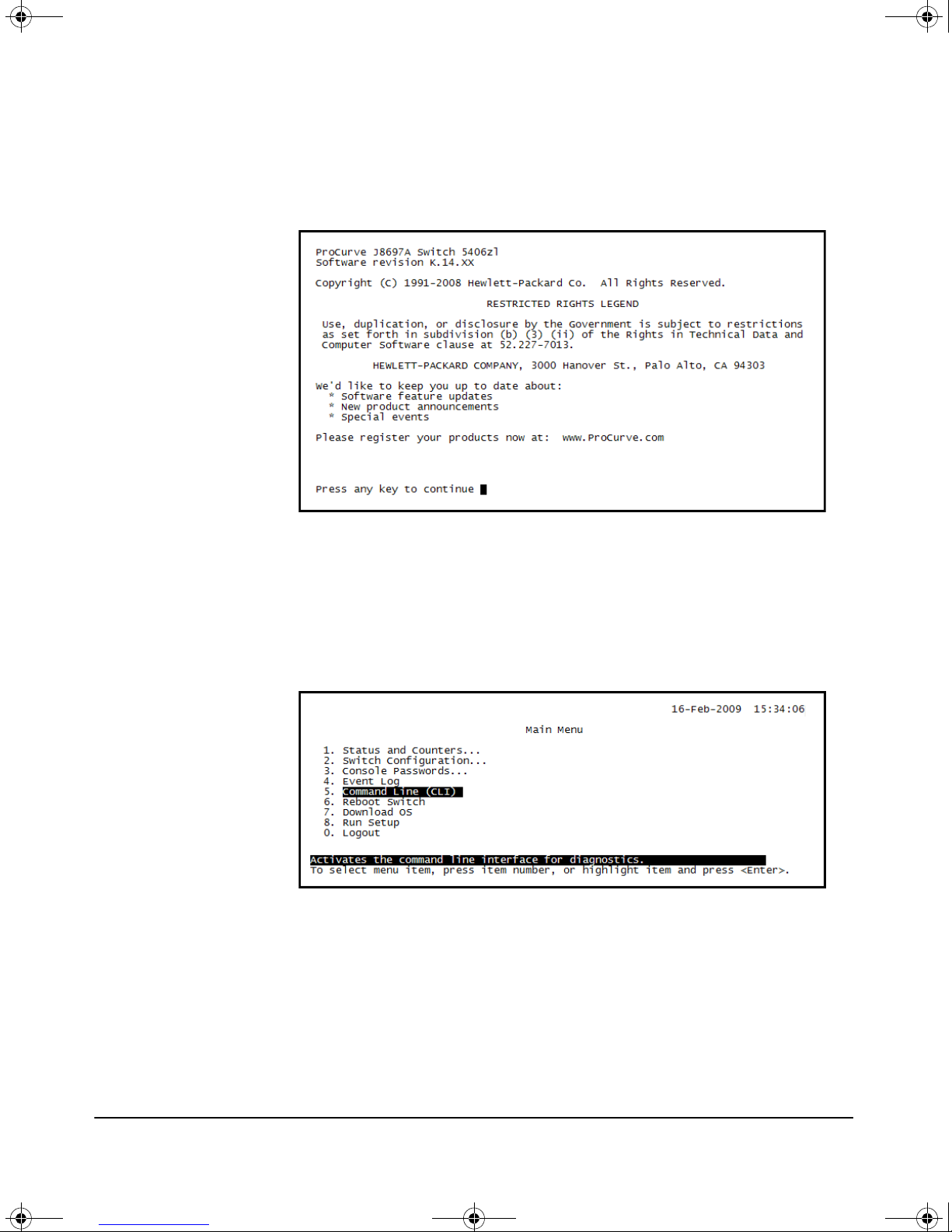
3. Open a terminal session with the switch and press Enter several times
until the welcome screen appears. (A different screen may appear if
another session was already open.)
4. Press any key to continue. The switch CLI prompt appears. It looks similar
to this:
ProCurve Switch 5406zl#
5. If instead, the switch menu is shown, return to the top-level menu and
then exit to the CLI by choosing Command Line (CLI) on the Main
Menu.
The switch CLI prompt appears.
Verify Switch Software Version
Before configuring the MSM765zl, verify that the switch software version is
compatible with the MSM765zl which requires at least version K.13.51 on the
switch.
2-2
MSM765-IGSG-5992-5964.book Page 3 Thursday, April 2, 2009 6:48 PM
At the switch CLI prompt, enter:
show version
The software version information is displayed like this:
Image stamp: ...
<date, time>
K.13.XX
...
If the switch software is out-of-date, update it according to the directions in
your switch documentation.
Activate the MSM765zl
Getting Started
Configure the Controller
The MSM765zl must be activated and booted before its own CLI can be used.
The MSM765zl uses the Service OS CLI on the MSM765zl for activation.
The MSM765zl ships with an HP ProCurve MSM765zl Software Activation
License Registration Card in the box. The License Registration ID is printed
on this card.
Obtain the Activation Hardware ID
This procedure is performed starting at the switch CLI prompt that looks like
this:
ProCurve Switch 5406zl#
Note The MSM765zl Service OS CLI is available once the MSM765zl Module Status
LED stays on green.
To obtain the activation hardware ID:
1. Change to the switch CLI configuration context:
config
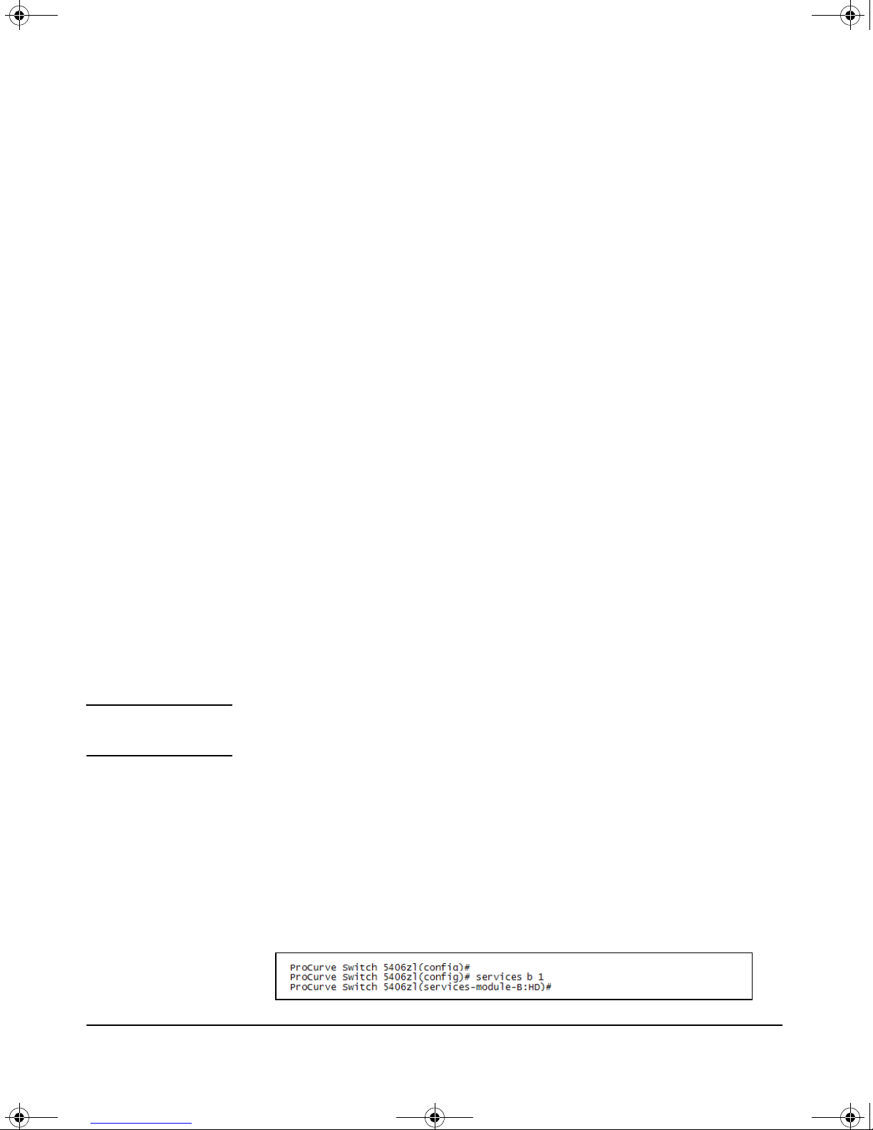
2. Launch the Service OS CLI:
services <slot-id> 1
Where <slot-id> identifies the slot containing the MSM765zl. Here is an
example with an MSM765zl in slot B:
2-3
 Loading...