

HP ProCurve 8212zl Installation And Getting Started Manual
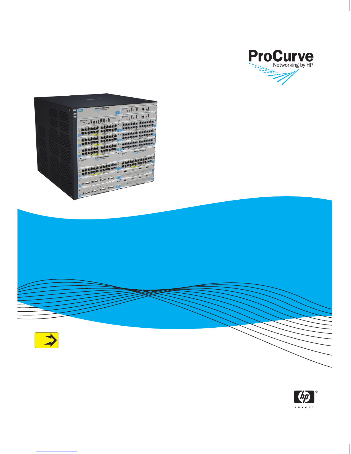
ProCurve Series 8212zl Switch
Installation and
Getting Started Guide
PoE
Power over Ethernet Devices
www.procurve.com


ProCurve Series 8200zl Switch
Installation and Getting Started Guide

© Copyright 2009 Hewlett-Packard Development Company, L.P.
Publication Number
5992-3072
January 2009
Edition 2
Applicable Products
ProCurve Switch 8212zl
(Replacement Chassis only)
ProCurve Switch 8212zl
(Base System)
ProCurve Switch zl Power Supply Shelf (J8714A)
(J9091A)
(J8715A)
Disclaimer
HEWLETT-PACKARD COMPANY MAKES NO WARRANTY
OF ANY KIND WITH REGARD TO THIS MATERIAL,
INCLUDING, BUT NOT LIMITED TO, THE IMPLIED
WARRANTIES OF MERCHANTABILITY AND FITNESS
FOR A PARTICULAR PURPOSE. Hewlett-Packard shall not
be liable for errors contained herein or for incidental or
consequential damages in connection with the furnishing,
performance, or use of this material.
The information contained herein is subject to change
without notice. The only warranties for HP products and
services are set forth in the express warranty statements
accompanying such products and services. Nothing herein
should be construed as constituting an additional warranty.
HP shall not be liable for technical or editorial errors or
omissions contained herein.
Hewlett-Packard assumes no responsibility for the use or
reliability of its software on equipment that is not furnished
by Hewlett-Packard.
Warranty
See the Customer Support/Warranty booklet included with
the product.
A copy of the specific warranty terms applicable to your
Hewlett-Packard products and replacement parts can be
obtained from your HP Sales and Service Office or
authorized dealer.
Hewlett-Packard Company
8000 Foothills Boulevard, m/s 5552
Roseville, California 95747-5552
http://www.procurve.com
Safety
Before installing and operating these products, please read
the “Installation Precautions” in chapter 2, “Installing the
Series 8200zl Switch”, and the safety statements in
appendix C, “Safety and Regulatory Statements”.

Contents
1 Introducing the ProCurve Series
8200zl Switch
Front of the Switch . . . . . . . . . . . . . . . . . . . . . . . . . . . . . . . . . . . . . . . . . . . . . . 1-3
LEDs . . . . . . . . . . . . . . . . . . . . . . . . . . . . . . . . . . . . . . . . . . . . . . . . . . . . . . 1-4
LED Mode Select Button and Indicator LEDs . . . . . . . . . . . . . . . . . . . 1-10
Console Port . . . . . . . . . . . . . . . . . . . . . . . . . . . . . . . . . . . . . . . . . . . . . . 1-11
Reset Buttons . . . . . . . . . . . . . . . . . . . . . . . . . . . . . . . . . . . . . . . . . . . . . . 1-11
Module Reset . . . . . . . . . . . . . . . . . . . . . . . . . . . . . . . . . . . . . . . . . . 1-11
System Reset . . . . . . . . . . . . . . . . . . . . . . . . . . . . . . . . . . . . . . . . . . . 1-11
Clear Button . . . . . . . . . . . . . . . . . . . . . . . . . . . . . . . . . . . . . . . . . . . . . . . 1-12
Back of the Switch . . . . . . . . . . . . . . . . . . . . . . . . . . . . . . . . . . . . . . . . . . . . . 1-13
Power Connector . . . . . . . . . . . . . . . . . . . . . . . . . . . . . . . . . . . . . . . . . . 1-13
Redundant Power Supply . . . . . . . . . . . . . . . . . . . . . . . . . . . . . . . . . . . . 1-14
Switch Features . . . . . . . . . . . . . . . . . . . . . . . . . . . . . . . . . . . . . . . . . . . . . . . 1-15
2 Installing the Series 8200zl Switch
Included Parts . . . . . . . . . . . . . . . . . . . . . . . . . . . . . . . . . . . . . . . . . . . . . . . . . . 2-1
Power Cords . . . . . . . . . . . . . . . . . . . . . . . . . . . . . . . . . . . . . . . . . . . . . . . . . . . 2-2
Installation Procedures . . . . . . . . . . . . . . . . . . . . . . . . . . . . . . . . . . . . . . . . . . 2-3
Summary . . . . . . . . . . . . . . . . . . . . . . . . . . . . . . . . . . . . . . . . . . . . . . . . . . . 2-3
1. Prepare the Installation Site . . . . . . . . . . . . . . . . . . . . . . . . . . . . . . . . 2-7
Cabling Infrastructure . . . . . . . . . . . . . . . . . . . . . . . . . . . . . . . . . . . . 2-7
Installation Location . . . . . . . . . . . . . . . . . . . . . . . . . . . . . . . . . . . . . 2-9
2. Mount the Switch . . . . . . . . . . . . . . . . . . . . . . . . . . . . . . . . . . . . . . . . . 2-9
Rack or Cabinet Mounting . . . . . . . . . . . . . . . . . . . . . . . . . . . . . . . . 2-9
Horizontal Surface Mounting . . . . . . . . . . . . . . . . . . . . . . . . . . . . . 2-13
3. Install Switch Modules . . . . . . . . . . . . . . . . . . . . . . . . . . . . . . . . . . . . 2-14
4. Install a Power Supply . . . . . . . . . . . . . . . . . . . . . . . . . . . . . . . . . . . . 2-17
5. Verify the Switch Passes Self Test . . . . . . . . . . . . . . . . . . . . . . . . . . 2-20
LED Behavior: . . . . . . . . . . . . . . . . . . . . . . . . . . . . . . . . . . . . . . . . . 2-21
iii

6. Install the Grounding Wire . . . . . . . . . . . . . . . . . . . . . . . . . . . . . . . . . 2-22
7. Connect the Switch to a Power Source . . . . . . . . . . . . . . . . . . . . . . 2-22
8. (Optional) Connect a Power Supply Shelf
to the switch . . . . . . . . . . . . . . . . . . . . . . . . . . . . . . . . . . . . . . . . . . . . . 2-23
EPS Operation . . . . . . . . . . . . . . . . . . . . . . . . . . . . . . . . . . . . . . . . . 2-23
Operating Characteristics of the EPS (J8714A) . . . . . . . . . . . . . . 2-24
Power Supply Shelf LEDs . . . . . . . . . . . . . . . . . . . . . . . . . . . . . . . . 2-24
Connecting the Power Supply Shelf . . . . . . . . . . . . . . . . . . . . . . . 2-25
9. Connect the Network Devices . . . . . . . . . . . . . . . . . . . . . . . . . . . . . . 2-26
10. (Optional) Connect a Console to the Switch . . . . . . . . . . . . . . . . . 2-28
Terminal Configuration . . . . . . . . . . . . . . . . . . . . . . . . . . . . . . . . . . 2-28
Direct Console Access . . . . . . . . . . . . . . . . . . . . . . . . . . . . . . . . . . . 2-29
Console Cable Pinouts . . . . . . . . . . . . . . . . . . . . . . . . . . . . . . . . . . 2-30
Telnet Console Access . . . . . . . . . . . . . . . . . . . . . . . . . . . . . . . . . . 2-30
Hot Swapping Switch Modules . . . . . . . . . . . . . . . . . . . . . . . . . . . . . . . . . . . 2-31
Adding or Replacing Modules . . . . . . . . . . . . . . . . . . . . . . . . . . . . . . . . 2-31
Changing the Module Type . . . . . . . . . . . . . . . . . . . . . . . . . . . . . . . . . . 2-31
Example Network Topologies . . . . . . . . . . . . . . . . . . . . . . . . . . . . . . . . . . . 2-33
Basic Connectivity . . . . . . . . . . . . . . . . . . . . . . . . . . . . . . . . . . . . . . . . . 2-33
Use as an Edge Switch . . . . . . . . . . . . . . . . . . . . . . . . . . . . . . . . . . . . . . 2-34
Optimizing the 10-GbE Port Configuration . . . . . . . . . . . . . . . . . . . . . 2-35
iv
3 Getting Started With Switch Configuration
Recommended Minimal Configuration . . . . . . . . . . . . . . . . . . . . . . . . . . 3-1
Using the Switch Setup Screen . . . . . . . . . . . . . . . . . . . . . . . . . . . . . . . . 3-2
Where to Go From Here . . . . . . . . . . . . . . . . . . . . . . . . . . . . . . . . . . . . . . 3-4
To Recover from a Lost Manager Password: . . . . . . . . . . . . . . . . . 3-4
Using the IP Address for Remote Switch Management . . . . . . . . . . . . . . . . 3-5
Starting a Telnet Session . . . . . . . . . . . . . . . . . . . . . . . . . . . . . . . . . . . . . 3-5
Starting a Web Browser Session . . . . . . . . . . . . . . . . . . . . . . . . . . . . . . . 3-5
Configuring the ProCurve Wireless Edge Services zl Module (J9051A) . . 3-7
Configuring an IP Address for the Module . . . . . . . . . . . . . . . . . . . . . . . 3-7
Configuring VLANs on the zl Switch . . . . . . . . . . . . . . . . . . . . . . . . . . . . 3-9
Determining a Module Configuration Backup Process . . . . . . . . . . . . 3-9
Configuring Wireless LAN Services . . . . . . . . . . . . . . . . . . . . . . . . . . . 3-10

4 Replacing Components
Replacing Power Supplies . . . . . . . . . . . . . . . . . . . . . . . . . . . . . . . . . . . . . . . . 4-2
Replacing Fan Trays . . . . . . . . . . . . . . . . . . . . . . . . . . . . . . . . . . . . . . . . . . . . . 4-5
Replacing the Management Module . . . . . . . . . . . . . . . . . . . . . . . . . . . . . . . . 4-6
Replacing the Management Module Compact Flash Card . . . . . . . . . . . . . 4-8
Installing a Compact Flash Card . . . . . . . . . . . . . . . . . . . . . . . . . . . . . . . 4-8
Replacing the Management Module Battery . . . . . . . . . . . . . . . . . . . . . . . . . 4-9
Installing a New Battery . . . . . . . . . . . . . . . . . . . . . . . . . . . . . . . . . . . . . . 4-9
Replacing the J9154x Module Compact Flash Card . . . . . . . . . . . . . . . . . . 4-11
Installing a Compact Flash Card . . . . . . . . . . . . . . . . . . . . . . . . . . . . . . 4-11
Replacing the J9154x Module Disk Drive . . . . . . . . . . . . . . . . . . . . . . . . . . 4-12
Installing a Disk Drive . . . . . . . . . . . . . . . . . . . . . . . . . . . . . . . . . . . . . . 4-12
5 Troubleshooting
Basic Troubleshooting Tips . . . . . . . . . . . . . . . . . . . . . . . . . . . . . . . . . . . . . . 5-1
Diagnosing with the LEDs . . . . . . . . . . . . . . . . . . . . . . . . . . . . . . . . . . . . . . . . 5-4
Proactive Networking . . . . . . . . . . . . . . . . . . . . . . . . . . . . . . . . . . . . . . . . . . . 5-9
Hardware Diagnostic Tests . . . . . . . . . . . . . . . . . . . . . . . . . . . . . . . . . . . . . . 5-10
Reasons for Resetting the Switch . . . . . . . . . . . . . . . . . . . . . . . . . . . . . 5-10
Methods of Resetting the Switch . . . . . . . . . . . . . . . . . . . . . . . . . . . . . . 5-10
Testing the Switch by Resetting It . . . . . . . . . . . . . . . . . . . . . . . . . . . . 5-11
Checking the Switch LEDs . . . . . . . . . . . . . . . . . . . . . . . . . . . . . . . 5-11
Checking Console Messages . . . . . . . . . . . . . . . . . . . . . . . . . . . . . . 5-11
Testing Twisted-Pair Cabling . . . . . . . . . . . . . . . . . . . . . . . . . . . . . . . . . 5-12
Testing Switch-to-Device Network Communications . . . . . . . . . . . . 5-12
Testing End-to-End Network Communications . . . . . . . . . . . . . . . . . 5-12
Restoring the Factory Default Configuration . . . . . . . . . . . . . . . . . . . . . . . 5-13
Downloading New Code . . . . . . . . . . . . . . . . . . . . . . . . . . . . . . . . . . . . . . . . 5-14
HP Customer Support Services . . . . . . . . . . . . . . . . . . . . . . . . . . . . . . . . . . 5-14
Before Calling Support . . . . . . . . . . . . . . . . . . . . . . . . . . . . . . . . . . . . . . 5-14
v

A Specifications
Physical . . . . . . . . . . . . . . . . . . . . . . . . . . . . . . . . . . . . . . . . . . . . . . . . . . . A-1
Electrical . . . . . . . . . . . . . . . . . . . . . . . . . . . . . . . . . . . . . . . . . . . . . . . . . A-1
Environmental . . . . . . . . . . . . . . . . . . . . . . . . . . . . . . . . . . . . . . . . . . . . . A-2
Acoustic . . . . . . . . . . . . . . . . . . . . . . . . . . . . . . . . . . . . . . . . . . . . . . . . . . A-2
Network Connectors . . . . . . . . . . . . . . . . . . . . . . . . . . . . . . . . . . . . . . . . A-2
Safety . . . . . . . . . . . . . . . . . . . . . . . . . . . . . . . . . . . . . . . . . . . . . . . . . . . . A-3
EMC compliance (Class A) . . . . . . . . . . . . . . . . . . . . . . . . . . . . . . . . . . A-3
Lasers . . . . . . . . . . . . . . . . . . . . . . . . . . . . . . . . . . . . . . . . . . . . . . . . . . . . A-3
B Switch Ports and Network Cables
Switch Ports . . . . . . . . . . . . . . . . . . . . . . . . . . . . . . . . . . . . . . . . . . . . . . . B-1
Twisted Pair . . . . . . . . . . . . . . . . . . . . . . . . . . . . . . . . . . . . . . . . . . . B-1
Fiber-Optic . . . . . . . . . . . . . . . . . . . . . . . . . . . . . . . . . . . . . . . . . . . . B-1
Cables . . . . . . . . . . . . . . . . . . . . . . . . . . . . . . . . . . . . . . . . . . . . . . . . . . . . B-2
Twisted-Pair . . . . . . . . . . . . . . . . . . . . . . . . . . . . . . . . . . . . . . . . . . . B-2
Note on 1000Base-T Cable Requirements B-2
Fiber-Optic Cables . . . . . . . . . . . . . . . . . . . . . . . . . . . . . . . . . . . . . . B-3
Copper Cables . . . . . . . . . . . . . . . . . . . . . . . . . . . . . . . . . . . . . . . . . B-4
Mode Conditioning Patch Cord for Gigabit-LX . . . . . . . . . . . . . . . . . . . . . B-5
Installing the Patch Cord . . . . . . . . . . . . . . . . . . . . . . . . . . . . . . . . . . . . B-6
Twisted-Pair Cable/Connector Pin-Outs . . . . . . . . . . . . . . . . . . . . . . . . . . . B-6
Straight-Through Twisted-Pair Cable for
10 Mbps or 100 Mbps Network Connections . . . . . . . . . . . . . . . . . . . . B-8
Cable Diagram . . . . . . . . . . . . . . . . . . . . . . . . . . . . . . . . . . . . . . . . . B-8
Pin Assignments . . . . . . . . . . . . . . . . . . . . . . . . . . . . . . . . . . . . . . . . B-8
Crossover Twisted-Pair Cable for
10 Mbps or 100 Mbps Network Connection . . . . . . . . . . . . . . . . . . . . . B-9
Cable Diagram . . . . . . . . . . . . . . . . . . . . . . . . . . . . . . . . . . . . . . . . . B-9
Pin Assignments . . . . . . . . . . . . . . . . . . . . . . . . . . . . . . . . . . . . . . . . B-9
Straight-Through Twisted-Pair Cable for
1000 Mbps Network Connections . . . . . . . . . . . . . . . . . . . . . . . . . . . . B-10
Cable Diagram . . . . . . . . . . . . . . . . . . . . . . . . . . . . . . . . . . . . . . . . B-10
Pin Assignments . . . . . . . . . . . . . . . . . . . . . . . . . . . . . . . . . . . . . . . B-10
vi

C Safety and Regulatory Statements
Safety Information . . . . . . . . . . . . . . . . . . . . . . . . . . . . . . . . . . . . . . . . . . . . . C-1
Informations concernant la sécurité . . . . . . . . . . . . . . . . . . . . . . . . . . . . . . C-2
Hinweise zur Sicherheit . . . . . . . . . . . . . . . . . . . . . . . . . . . . . . . . . . . . . . . . . C-3
Considerazioni sulla sicurezza . . . . . . . . . . . . . . . . . . . . . . . . . . . . . . . . . . . C-4
Consideraciones sobre seguridad . . . . . . . . . . . . . . . . . . . . . . . . . . . . . . . . C-5
Safety Information (Japan) . . . . . . . . . . . . . . . . . . . . . . . . . . . . . . . . . . . . . . C-6
Safety Information (China) . . . . . . . . . . . . . . . . . . . . . . . . . . . . . . . . . . . . . . C-7
EMC Regulatory Statements . . . . . . . . . . . . . . . . . . . . . . . . . . . . . . . . . . . . . C-8
U.S.A. . . . . . . . . . . . . . . . . . . . . . . . . . . . . . . . . . . . . . . . . . . . . . . . . . . . . C-8
Canada . . . . . . . . . . . . . . . . . . . . . . . . . . . . . . . . . . . . . . . . . . . . . . . . . . . C-8
Australia/New Zealand . . . . . . . . . . . . . . . . . . . . . . . . . . . . . . . . . . . . . . C-8
Japan . . . . . . . . . . . . . . . . . . . . . . . . . . . . . . . . . . . . . . . . . . . . . . . . . . . . . C-8
Korea . . . . . . . . . . . . . . . . . . . . . . . . . . . . . . . . . . . . . . . . . . . . . . . . . . . . . C-9
Taiwan . . . . . . . . . . . . . . . . . . . . . . . . . . . . . . . . . . . . . . . . . . . . . . . . . . . C-9
Regulatory Model Identification Number . . . . . . . . . . . . . . . . . . . . . . C-9
Regulatory Information (China) . . . . . . . . . . . . . . . . . . . . . . . . . . . . . C-11
D Recycle Statements
Waste Electrical and Electronic Equipment (WEEE) Statements . . . . . . D-1
Index
vii


Introducing the ProCurve Series
8200zl Switch
The ProCurve Series 8200zl Switch is a multiport modular switch that provides
Layer 3 routing features, and features low latency for high-speed networking.
This chapter describes your Series 8200zl Switch including:
■ Front and back of the switches
■ Features
■ Switch operation overview
The Series 8212zl Switch is typically ordered as the base system (J8715A) with
one management module, one system support module, two fabric modules,
and the fan tray pre-installed. A spare chassis-only (J9091A) can be ordered,
but it only comes with a fan tray pre-installed. All other modules are removed
from a failed chassis and re-installed into the spare chassis.
1
Introducing the ProCurve
Series 8200zl Switch
Note The 8200zl (J9091A) ships empty as a spare chassis, not pictured.
1-1
Series 8200zl Switch
Introducing the ProCurve
Introducing the ProCurve Series 8200zl Switch
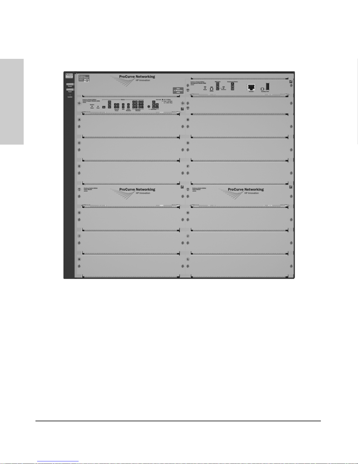
Figure 1-1. ProCurve Switch 8212zl (J8715A) Base System
See “Switch Features” on page 1-15 for a list of the switch modules that can
be installed in the ProCurve Series 8200zl Switch (modules available when
this manual was printed).
1-2
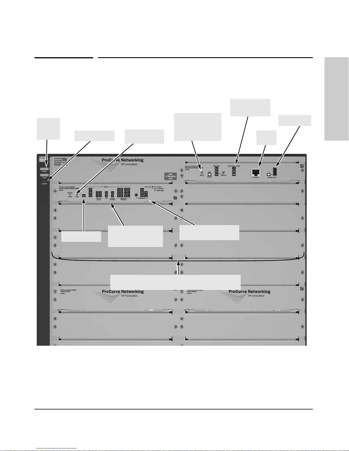
Power
and Fault
LEDs
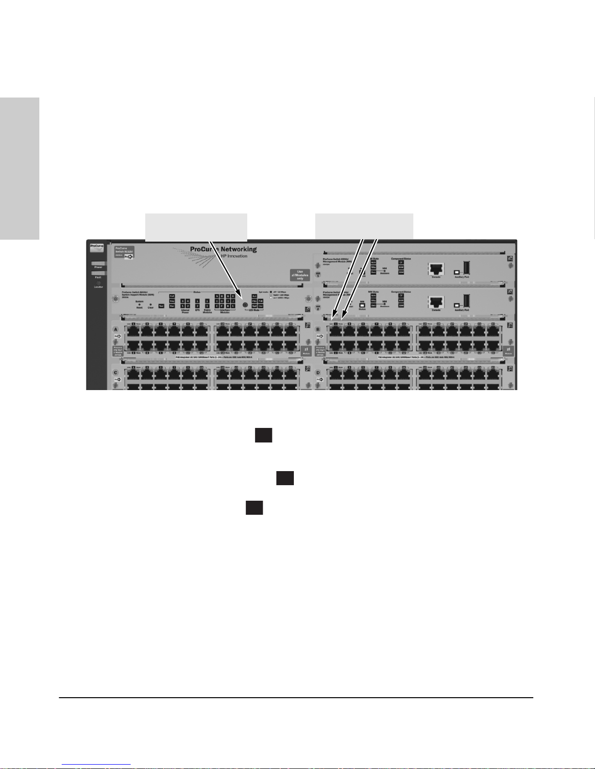
Front of the Switch
Locator LED
Reset and Clear
buttons
Introducing the ProCurve Series 8200zl Switch
Management
Module Reset
button, and Status
LEDs
Front of the Switch
Introducing the ProCurve
Series 8200zl Switch
Component
Status LEDs
Auxiliary Port
Console
Port
Self Test LED
Status LEDs for the
Fans, Power Supplies,
and Switch Modules
Switch Modules and slots
with Link and Mode LEDs for each port located on each module
LED Mode Select button
and indicator LEDs
Figure 1-2. Front of 8212zl Switch, Base System
1-3
Introducing the ProCurve Series 8200zl Switch
Front of the Switch
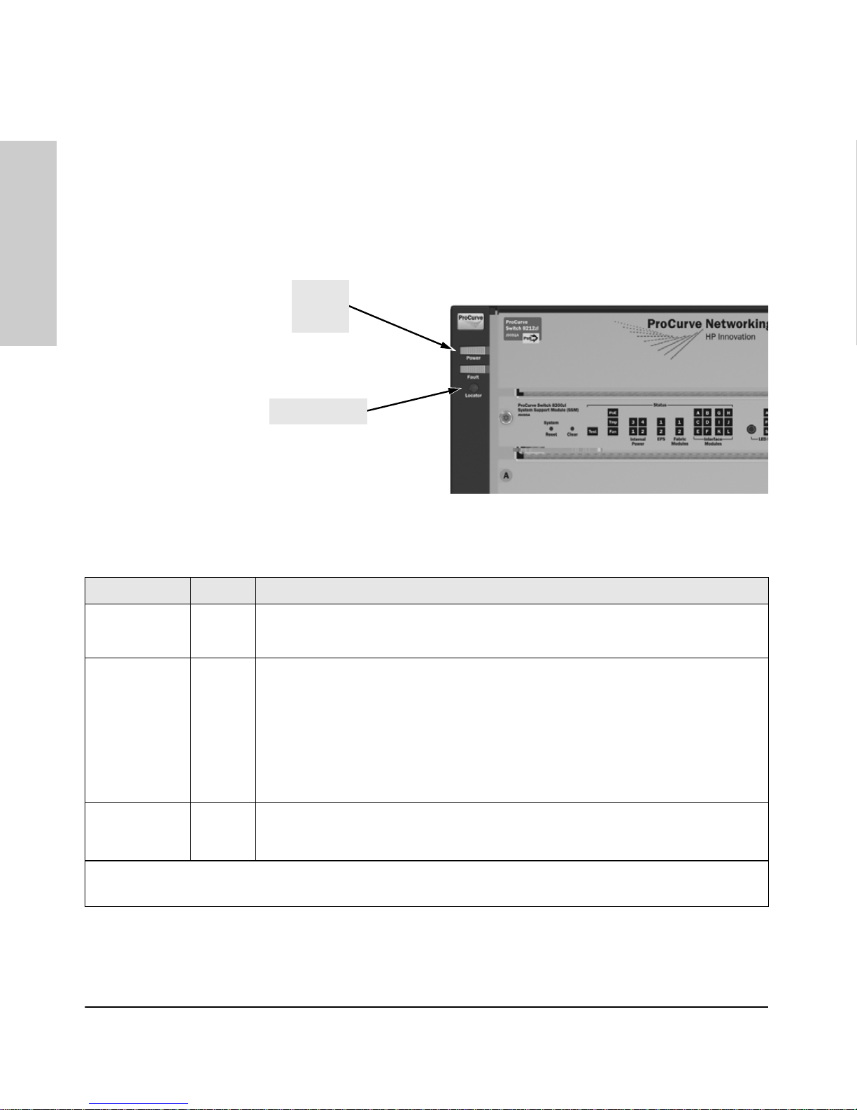
LEDs
As described in the following tables, there are LEDs on the switch chassis and
on the switch modules that keep you informed of the status of the switch and
the network connections.
Series 8200zl Switch
Introducing the ProCurve
and Fault
Locator LED
Figure 1-3. Switch Chassis LEDs
Table 1-1. Switch Chassis LEDs
LEDs State Meaning
Power
(green)
Fault
(orange)
On The switch is receiving power.
Off The switch is NOT receiving power.
Off The normal state; indicates that there are no fault conditions on the switch.
1
Blinking
A fault has occurred on the switch, one of the switch modules, an individual port, a power
supply, or a fan. The Status LED for the module or other device with the fault will flash
simultaneously.
Power
LEDs
On On briefly at the beginning of switch self test after the switch is powered on or reset. If on
for a prolonged time, the switch has encountered a fatal hardware failure, or has failed its
self test. See chapter 5, “Troubleshooting” for more information.
Locator
(blue)
1
The blinking behavior is an on/off cycle once every 1.6 seconds, approximately.
2
The blinking behavior is an on/off cycle once every 0.5 seconds, approximately.
On
Blinking
Off
The Locator LED is used to locate a specific chassis in a area full of chassis. The LED can
be set to be on solid or blink for a specified number of minutes (1-1440). The default is 30
minutes. Use the command “chassislocate”.
1-4
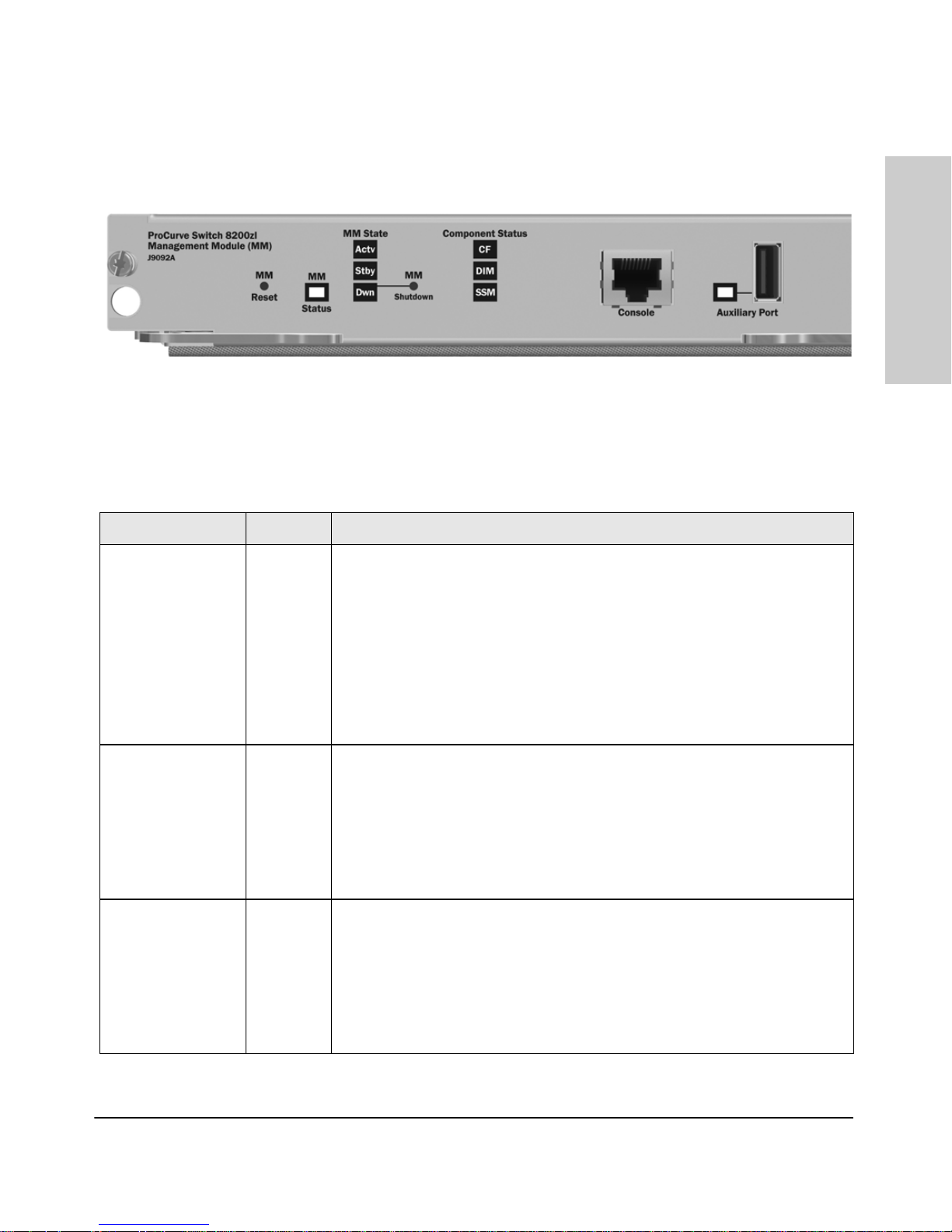
Figure 1-4. Management Module LEDs
Table 1-2. Management Module LEDs
These LEDs are located on the Management Module.
LED State Meaning
Introducing the ProCurve Series 8200zl Switch
Front of the Switch
Introducing the ProCurve
Series 8200zl Switch
Auxiliary (green/
orange) For more
information see the
Management and
Configuration Guide
for your switch.
DIM
(green/orange)
CF
(green/orange)
Blinking
1
green
Indicates the switch is processing a USB command file.
On green The switch has finished processing the USB command file successfully.
Blinking
orange
Indicates an error condition.
2
Off Indicates that no USB device has been inserted, or that the inserted USB device
cannot be recognized, or that no command file can be found on the inserted USB
device.
On green DIM (Dual in-line Memory Module) status is known and fault free.
Off DIM status is unknown.
Blinking
orange
If DIM, Fault, and Self Test LEDs are blinking, DIMM failed self-test.
1
If DIM and Fault LEDs are blinking, an operational fault has occurred.
If fast blinking (400ms On and 400ms Off), an operational alert occurred and is
unresolved.
On green CF (CompactFlash) status is known and fault free
Off
Blinking
orange
CF status is unknown.
If CF, Fault, and Self Test LEDs are blinking, CompactFlash failed self-test.
1
If CF and Fault LEDs are blinking, an operational fault has occurred.
If fast blinking (400ms On and 400ms Off), an operational alert occurred and is
unresolved (for example, CompactFlash not present).
1-5
Introducing the ProCurve Series 8200zl Switch
Front of the Switch
Series 8200zl Switch
Introducing the ProCurve
SSM
(green/orange)
On green The communication link with the SSM (system support module) is good.
Off
Blinking
orange
The communication link with the SSM is bad or there is no SSM installed.
The communication link with the SSM is bad or the SSM itself has failed.
1
Module Status LED On green The Management Module is active and has passed all self-tests.
If Module Status, Fault and Self Test LEDs are blinking, this MM has failed self-test
1
If Module Status and Fault LEDs are blinking, an operational fault has occurred.
module.
MM State LEDs
(green)(
Blinking
orange
Actv Indicates the Management Module is active and is the primary management
Stby Indicates that this Management Module is the standby management module.
Dwn Indicates that this Management Module has been shutdown.
1
The blinking behavior is an on/off cycle once every 1.6 seconds, approximately.
2
The blinking behavior is an on/off cycle once every 0.5 seconds, approximately.
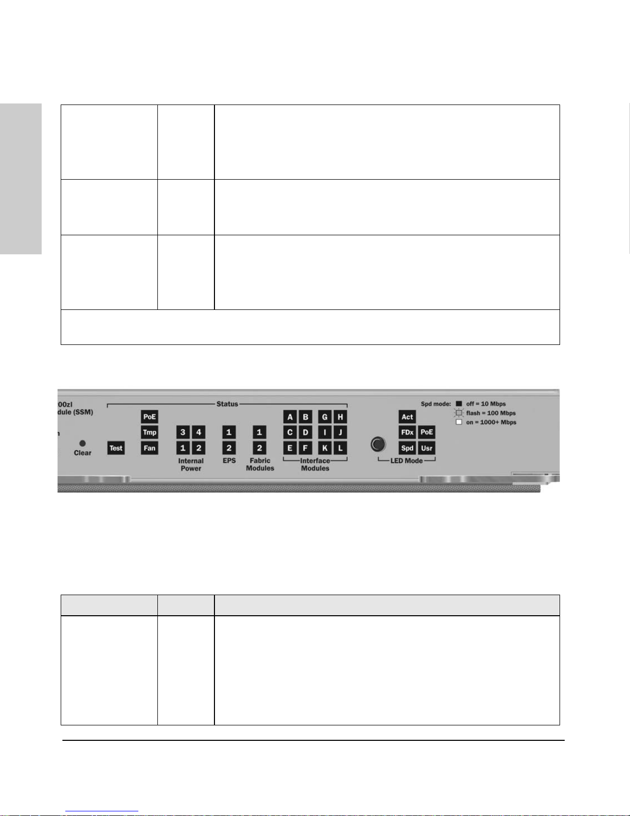
Figure 1-5. System Support Module LEDs
Table 1-3. System Support Module LEDs
These LEDs are located on the System Support Module.
LED State Meaning
Te st
Off The normal operational state; the switch is not undergoing self test.
(green/orange)
On green The switch self test and initialization are in progress after you have power cycled
Blinking
1
orange
1-6
or reset the switch. The switch is not operational until this LED goes off. The Self
Test LED also comes on briefly when you “hot swap” a module into the switch
and the module is automatically self tested.
The port has failed self test. The switch Fault, Self Test LEDs, and appropriate
module status LEDs will flash simultaneously.
Introducing the ProCurve Series 8200zl Switch
Front of the Switch
PoE
(green/orange)
Tmp
(green/orange)
Fan
(green/orange)
Internal Power 1-4
(green/orange numbers
corresponding to
the power supply
positions)
EPS (1 and 2)
(green/orange)
On green
Off
Blinking
orange
Blinking
orange
If any PoE modules are installed.
If no PoE modules are installed.
Internal PoE fault.
1
External load fault or denied PoE power.
2
Off Switch temperature is normal.
Blinking
1
An over temperature condition has been detected.
On green The cooling fans are operating normally.
Blinking
orange
One or more of the cooling fans have failed. The switch Fault LED will be blinking
1
simultaneously.
On green A power supply is installed in the position in the back of the switch corresponding
to the number, and the supply is plugged in to an active AC power source. As
shipped, the switch has a single power supply in position 1.
Off A power supply is not installed in the position corresponding to the number.
Blinking
orange
The power supply installed in the position corresponding to the number is not
1
plugged in to an active AC power source, or has experienced a fault. The switch
Fault LED will be blinking simultaneously.
On green
Off
An External Power Supply is connected.
No External Power Supply is connected.
Introducing the ProCurve
Series 8200zl Switch
Fabric Modules
(1 and 2)
(green/orange)
Blinking
1
orange
On green
Off
Blinking
1
orange
The External Power Supply has a fault, or is connected but not plugged into AC
power.
A Fabric Module is installed and functioning correctly.
A Fabric Module is not installed or has failed.
The Fabric Module has a fault.
The switch Fault LED will be blinking simultaneously.
1-7
Introducing the ProCurve Series 8200zl Switch
Front of the Switch
Series 8200zl Switch
Introducing the ProCurve
LED Mode Select
(5 green LEDs)
Modules A-L (green
- letters
corresponding to
the switch module
slots)
Act Indicates that the port Mode LEDs are displaying network activity information.
FDx Indicates that the port Mode LEDs are lit for ports that are in Full Duplex Mode.
PoE Indicates which ports are supplying PoE power.
• If the Mode LED is on the port is providing PoE power.
• If the Mode LED is off the port is not providing PoE power.
• If the Link LED is on the port is enabled for PoE.
• If the Link LED is off the port is disabled for PoE.
• If the Link LED is blinking, the port has an error or the port is denied power due
to insufficient power.
Spd Indicates the Port LEDs are displaying the connection speed at which each port
is operating:
• if the Port LED is off, the port is operating at 10 Mbps
• if the Port LED is blinking, the port is operating at 100 Mbps
• if the Port LED is on continuously, the port is operating at 1000 Mbps
Usr Reserved for future development
On A module is installed in the switch module slot corresponding to the letter and
the module is undergoing or has passed self test. This also occurs when you
install a module when the switch is already powered on (“hot swap”).
Off A module is not installed in the switch module slot corresponding to the letter.
Blinking
1
The module status LED flashes very briefly when a module is being hot swapped.
If the LED flashes for a prolonged time, the module in the slot corresponding to
the letter has failed self test or encountered some other fault condition. See
chapter 5, “Troubleshooting” for a more information.
In PoE Mode:
1
The blinking behavior is an on/off cycle once every 1.6 seconds, approximately.
2
The blinking behavior is an on/off cycle once every 0.5 seconds, approximately.
On green
Blinking
1
orange
Blinking
2
orange
Off
PoE is ok for this slot.
PoE internal fault for this slot.
PoE load fault or insufficient power for this slot.
The module in this slot is not a PoE module.
1-8
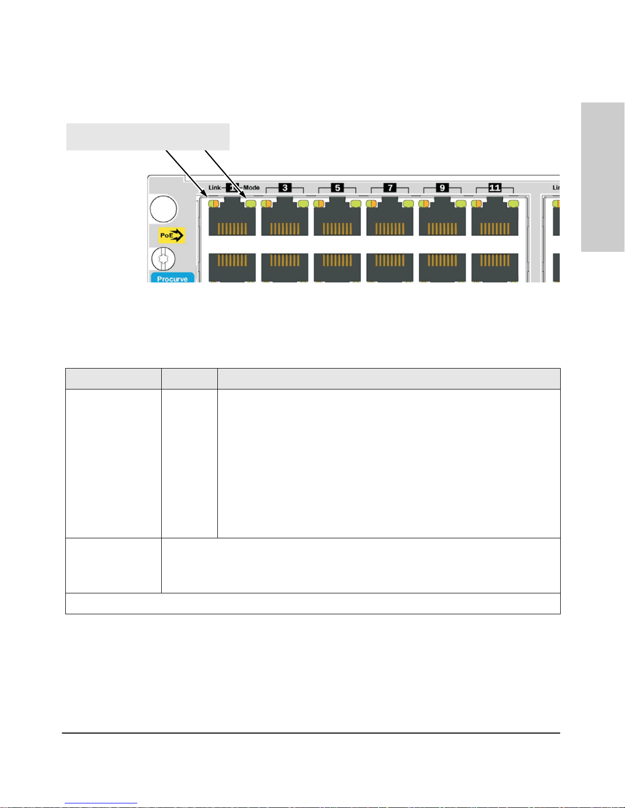
Switch Modules with Link and Mode LEDs
for each port located on each module
Figure 1-6. Switch Module LEDs
Table 1-4. Switch Module LEDs
These LEDs are located on the modules themselves, one pair for each port.
Introducing the ProCurve Series 8200zl Switch
Front of the Switch
Introducing the ProCurve
Series 8200zl Switch
LED State Meaning
Link On Indicates the port is enabled and receiving a link beat signal (for the twisted-pair
ports), or a strong enough light level (for the fiber-optic ports) from the connected
device.
Off One of these conditions exists:
• no active network cable is connected to the port
• the port is not receiving link beat or sufficient light
• the port has been disabled through the switch console, the web browser
interface, ProCurve Manager, or other network management tool.
Blinking
1
The port has failed self test. The switch Fault, Self Test LEDs, and appropriate
module status LEDs will flash simultaneously.
Mode Depending on the mode selected, displays the following: network activity information, whether
the port is configured for Full Duplex operation, maximum speed operation, or whether PoE
power is being supplied or not. See “LED Mode Select Button and Indicator LEDs” below for
more information.
1
The blinking behavior is an on/off cycle once every 1.6 seconds, approximately.
1-9
Series 8200zl Switch
Introducing the ProCurve
Introducing the ProCurve Series 8200zl Switch
Front of the Switch
LED Mode Select Button and Indicator LEDs
To optimize the amount of information that can be displayed for each of the
switch ports, the Series 8212zl Switch uses a Mode LED for each port. The
operation of this LED is controlled by the LED Mode Select button on the
switch chassis, and the current selection is indicated by the mode indicator
LEDs near the button. Press the button to change from one mode to the next.
LED Mode Select button
and indicator LEDs
Mode LEDs
(Link and Mode)
Figure 1-7. Mode LEDs and LED Mode Select Button
■ If the Activity indicator LED is lit, each port Mode LED displays
Act
activity information for the port—it flickers as network traffic is received
and transmitted through the port.
■ If the Full Duplex indicator LED is lit, the port Mode LEDs light for
FDx
those ports that are operating in full duplex.
■ If the speed indicator LED is lit, the port LEDs behave as follows to
Spd
indicate the connection speed for the port:
• Off = 10 Mbps
• Blinking = 100 Mbps (the blinking behavior is a repeated on/off cycle
once every 0.5 sec.)
• On = 1000 Mbps
1-10

Introducing the ProCurve Series 8200zl Switch
Front of the Switch
■ If the PoE indicator LED is lit, the Link and Mode LEDs indicate PoE
status:
Link LED:
• On = PoE is enabled on this port
• Off = PoE is disabled on this port.
• Slow Blinking = Internal PoE fault on this port.
• Fast Blinking = This port is denied PoE power or has an external load
fault.
Mode LED:
• On = PoE power is be supplied on this port
• Off = PoE is not being supplied on this port.
PoE
Console Port
This port is used to connect a console to the switch by using the serial cable
supplied with the switch. This connection is described under “Connecting a
Console to the Switch” in chapter 2, “Installing the Series 8212zl Switch”. The
console is a full-featured interface that can be used to configure, monitor, and
troubleshoot the switch. It can be run on a PC, laptop, or handheld device
emulating a VT-100 terminal, or on a standard VT-100 terminal.
Introducing the ProCurve
Series 8200zl Switch
Reset Buttons
Module Reset
This button, located on the Management module, will reset the Management
module only.
System Reset
This button, located on the System Support Module, will reset the switch when
powered on. This action clears any temporary error conditions that may have
occurred, executes the switch self test, and resets all network activity counters to zero.
The counters are displayed in the switch console interface, the switch web
browser interface, and through SNMP network management applications,
such as ProCurve Manager.
Press the Reset button also after changing the module type that is installed in
any of the switch module slots while the switch is powered on. In this case,
the switch must be reset to initialize the new module type. See “Hot Swapping
Switch Modules” on page 2-31.
1-11

Series 8200zl Switch
Introducing the ProCurve
Introducing the ProCurve Series 8200zl Switch
Front of the Switch
Clear Button
This button, located on the System Support Module, is used for the following
purposes:
■ Deleting Passwords - When pressed by itself for at least one second, the
Clear button deletes any switch console access passwords that you may
have configured. Use this feature if you have misplaced the password and
need console access.
This button is provided for your convenience, but its presence means that
if you are concerned with the security of the switch configuration and
operation, you should make sure the switch is installed in a secure
location, such as a locked wiring closet.
■ Restoring Factory Default Configuration - When pressed with the
Reset button in a specific pattern, the Clear button clears any configuration changes you may have made through the switch console, the web
browser interface, or SNMP management, and restores the factory default
configuration to the switch. For the specific method to restore the factory
default configuration, see “Restoring the Factory Default Configuration”
in chapter 5, “Troubleshooting” of this manual.
1-12
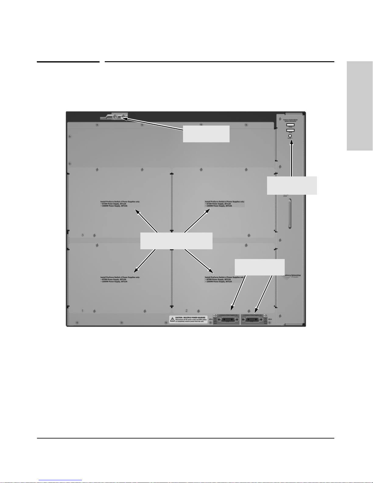
Back of the Switch
.
Grounding lug
mounting holes
Introducing the ProCurve Series 8200zl Switch
Back of the Switch
Introducing the ProCurve
Series 8200zl Switch
Fan Power, Fault
and Locator LEDs
Slots for installing optional
redundant power supply
External PoE
power connectors
Figure 1-8. Back of a 8212zl Switch with two Power Supplies
Power Connector
The Series 8200zl Switch does not have a power switch; it is powered on when
connected to an active AC power source. The Series 8200zl Switch automatically adjusts to any voltage between 100-127 and 200-240 volts when using the
J8712A power supply, and 200-240 volts only when using the J8713A power
supply, and either 50 or 60 Hz.There are no voltage range settings required.
1-13

Series 8200zl Switch
Introducing the ProCurve
Introducing the ProCurve Series 8200zl Switch
Back of the Switch
Redundant Power Supply
Load-sharing redundant power supplies (ProCurve Switch zl 875 W Power
Supply, J8712A or a ProCurve Switch zl 1500 W Power Supply J8713A) can be
installed in the back of the Series 8200zl Switch. To provide redundancy, each
power supply should be connected to different AC power sources. Then, if
one AC power source fails, the switch will continue to run.
Caution The switch redundant power supply is hot swappable, but, as indicated by the
caution statement on the power supply, it must be disconnected from AC
power before being installed or removed.
CAUTION:
.
Refer to the installation guide for proper power cord selection
.
Disconnect AC power from the power supply BEFORE installing or
removing the supply. Otherwise, damage to the equipment may result.
Because the switch can run on a single supply, removing a redundant supply
will not interrupt switch operation. However, on the 8212zl one power supply
will only supply enough power to run the module slots A-F. Slots G-L will not
receive any power unless there are at least two power supplies installed.
.
When power is restored to a second (or more) power supplies, a system reload
or interface module reset may be required to restore operation to slots G-L.
For more information regarding power see the:
■ ProCurve Switch zl Internal Power Supply Installation Guide.
■ ProCurve PoE (Power over Ethernet) Devices Planning and
Implementation Guide.
1-14

Introducing the ProCurve Series 8200zl Switch
Switch Features
Switch Features
The features of the Series 8200zl Switch include:
■ If there are two Management modules installed in the switch, they are hot
swappable one at a time.
■ The two Fabric modules are hot swappable one at a time.
■ 12 slots for installing any of the available Switch zl Modules.
Supported Modules: As of this printing, the supported zl modules
include:
• 24-port 10/100/1000-T zl PoE Module (J8702A) -- which can provide
Power over Ethernet (PoE) power to 802.3af compliant (and some
pre-standard) devices. For more information on PoE power refer to
the ProCurve PoE (Power over Ethernet) Devices Planning and
Implementation Guide. For more information on the J8702A module
refer to the ProCurve Switch zl Modules Installation Guide
• 20-port Gig-T and 4-port mini-GBIC/SFP zl PoE Module (J8705A)-- into
which you can install the supported mini-GBICs, the Gigabit-SX LC
mini-GBIC (J4858B), the Gigabit-LX LC mini-GBIC (J4859B), the
Gigabit-LH LC mini-GBIC (J4860B), and the 1000Base-T mini-GBIC
(J8177A)
• 24-port mini-GBIC zl Module (8706A)-- into which you can install the
supported mini-GBICs, see above
• 4-port 10Gig-X2 zl Module (J8707A) -- into which you can install the
supported X2 fiber optic transceivers:
• 10 Gigabit-X2-SC SR Optic transceiver (J8436A)
• 10 Gigabit-X2-SC LR Optic transceiver (J8437A)
• 10 Gigabit-X2-SC ER Optic transceiver (J8438A)
• 10 Gigabit-X2-SC LRM Optic transceiver (J9144A)
• 10 Gigabit-X2-CX4 copper transceiver (J8440B)
• 10 Gigabit-X2-CX4 Optical Media Converter (J8439A)
• 4-port 10Gig-CX4 zl Module (J8708A)
• Wireless Edge Services zl Module (J9051A) and Redundant Wireless
Services zl Module (J9052A)
Introducing the ProCurve
Series 8200zl Switch
• Services zl Module (J9154x) where “x” is the version letter A, B, and
■ the modules can be installed in any order and in any combination and can
be “hot swapped”
so on
1-15

Series 8200zl Switch
Introducing the ProCurve
Introducing the ProCurve Series 8200zl Switch
Switch Features
■ the supported mini-GBICs can be hot swapped into the mini-GBIC zl
Module
■ high performance—The 8212zl Switch has a routing/switching capacity of
576 Gbps, with a switch fabric speed of 692 Gbps and a throughput of 428
Mpps.
■ plug-and-play networking—all ports are enabled—just connect the
network cables to active network devices and your switched network is
operational.
■ automatic learning of the network addresses in the switch’s 64,000-
address forwarding table, with configurable address aging value.
■ full-duplex operation available on all ports.
■ easy management of the switch through several available interfaces:
• web browser interface—an easy to use built-in graphical interface
that can be accessed from common web browsers.
• console interface—a full featured, easy to use, VT-100 terminal interface for out-of-band switch management, or for telnet access to the
switch. The console includes complete switch management through
a command line interface (CLI) and a slightly reduced feature set
accessible through an intuitive menu interface.
• ProCurve Manager—an SNMP-based graphical interface that is used
to manage your entire network, included with your new switch.
• Supported by ProCurve Network Manager—an HP OpenView application that accurately displays your switch on network maps and
provides a graphical interface for configuring and monitoring your
switch.
■ support for the Spanning Tree Protocol to eliminate network loops.
■ support for up to 2048 IEEE 802.1Q-compliant VLANs so you can divide
the attached end nodes into logical groupings that fit your business needs.
■ Layer 3 routing functionality:
•IP static routes
• RIP V1 and V2
• IRDP - ICMP Router Discovery Protocol
• OSPF- Open Shortest Path First
■ support for many other advanced features to enhance network perfor-
mance, security, and control— for a description, see the Management and
Configuration Guide which is on the ProCurve Web site. See page 5-1 for
details.
■ Support for IEEE 802.3af standard and pre-standard PoE devices.
1-16
2
Installing the Series 8200zl Switch
The Series 8200zl Switch is easily installed. It comes with an accessory kit that
includes the brackets for mounting the switch in a standard 19-inch telco rack,
or in an equipment cabinet. The switch has rubber feet already attached so
they can be securely located on a horizontal surface. This chapter shows you
how to install your Series 8200zl Switch.
WARNING To avoid possible personal injury, be careful when lifting the chassis
out of the shipping box. The Switch 8212zl chassis base system weighs
approximately 50.45 pounds as shipped and 44.75 pounds when empty.
See “Installation Precautions” on page 2-5 for additional safety
considerations when handling this product.
Installing the Series 8200zl
Switch
Included Parts
The Series 8200zl Switch has the following components shipped with it:
■ ProCurve Series 8200zl Switch Installation and Getting Started Guide,
this manual
■ PoE (ProCurve Power over Ethernet) Devices Planning and
Implementation Guide
■ ProCurve Manager - CD ROM and booklet
■ Customer Support/Warranty booklet
■ Accessory kit
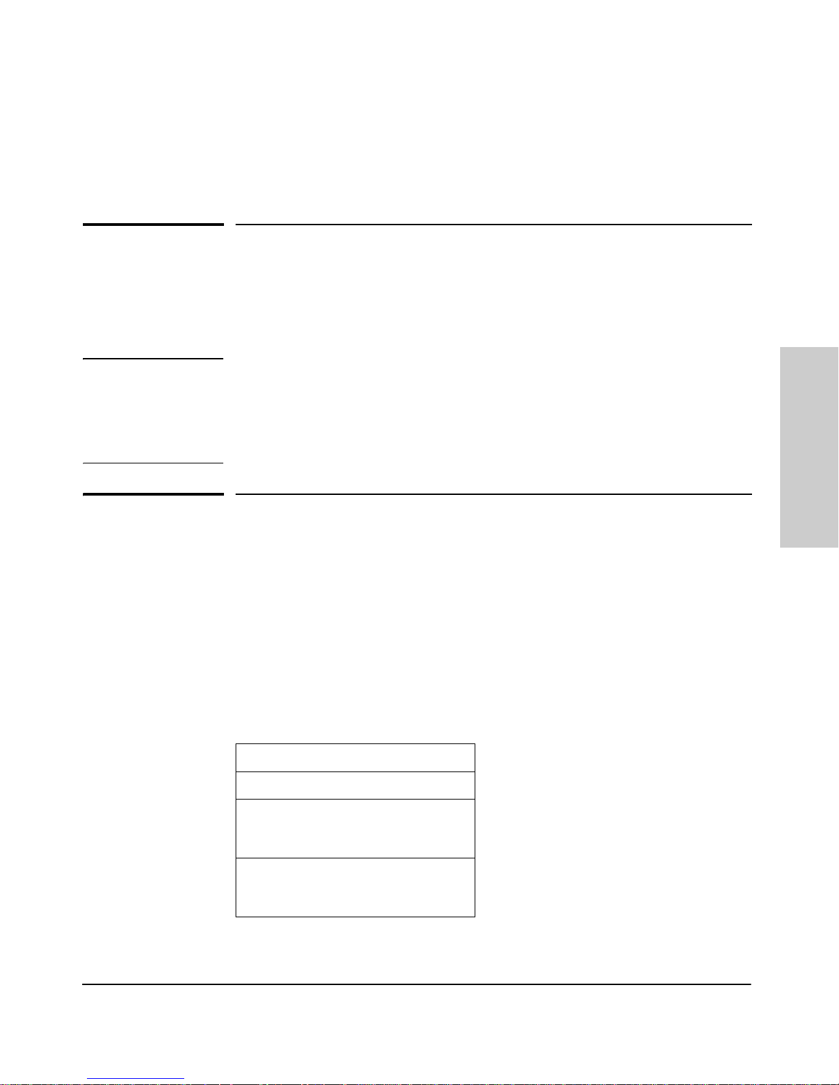
8212zl Accessory Kit (5070-2983)
two mounting brackets
eight 10 mm M4 screws to attach
the mounting brackets to the
switch
four 5/8-inch number 12-24
screws to attach the switch to a
rack
■ Console cable (5188-6699)
2-1
Installing the Series 8200zl Switch
Power Cords
Power Cords
Power cords and power supplies must be ordered separately, they are not
included with the chassis when shipped. Order one of the following power
cords depending on your region and model of power supply.
Region J8712A J8713A
Switch
Installing the Series 8200zl
Japan Power
Cord Warning
Australia/New Zealand
China
Continental Europe
Denmark
Japan
Switzerland
United Kingdom/
Hong Kong/Singapore
United States/Canada/
Mexico
South Africa
Taiwan
Israel
Thailand
8121-0857
8121-1034
8120-5336
8120-5340
8120-5342
8120-5339
8120-5334
8121-0973
8120-5341
8121-0941
8121-1009
8121-0671
8121-0871
8121-0924
8120-6899
8120-6897
8120-6903
8120-6897
8120-6898
8120-6903
8121-0915
8120-6903
8121-1010
8121-0675
2-2

Installing the Series 8200zl Switch
Installation Procedures
Installation Procedures
WARNING To avoid personal injury or product damage, read the safety warnings
on page 2-5 and installation precautions on page 2-6 and follow the
rack mounting guidelines on page 2-9. Due to product weight, two or
more persons are required to handle and mount the 8212zl.
Summary
Follow these easy steps to install your switch. The rest of this chapter provides
details on these steps.
1. Prepare the installation site (page 2-7). Make sure the physical
environment into which you will be installing the switch is properly
prepared including having the correct network cabling ready to connect
to the switch, and having a good location for the switch. See page 2-6 for
some installation precautions.
2. Mount the switch (page 2-9). The Series 8200zl Switch is a large heavy
chassis, therefore ProCurve Networking recommends mounting the
empty chassis before populating it with modules or power supplies. It can
be mounted in a 19-inch telco rack, in an equipment cabinet, or on a
horizontal surface. An optional Rail Mounting Kit (5070-0145) is available
for mounting the Series 8200zl Switch in a cabinet suitable for shipping.
See the installation details for more information.
3. Install switch modules (page 2-14). The Series 8200zl Switch has 12
universal slots for installing any of the ProCurve Switch zl modules.
Depending on where you will install your Series 8200zl Switch, it may be
easier to install the modules first. The modules are “hot swappable”
though, so they can also be installed and removed after the switch is
powered on.
Installing the Series 8200zl
Switch
Note Make sure you use only ProCurve Switch zl Modules in your Series 8200zl
Switch.
4. Install power supplies (page 2-17). The Series 8200zl Switch supports
up to four power supplies. It may be easier to install the power supplies
before mounting the switch. The switch must have at least one power
supply to operate.
2-3

Installing the Series 8200zl Switch
Installation Procedures
Switch
5. Verify the switch passes self test (page 2-20). This is a simple process
of plugging the switch into a power source and observing that the LEDs
on the switch’s front panel and on the modules show correct operation.
It may be easier to verify if the switch passes self test before mounting
the switch.
6. Install the Grounding Wire (page 2-22). If a grounding wire is to be
attached to the switch chassis, the grounding lug must be removed and a
wire crimped to it and the grounding lug must be reinstalled.
7. Connect the switch to a power source (page 2-22). Once the switch
is mounted, plug it in to the nearby main power source.
8. (Optional) connect a Power Supply Shelf (page 2-23). You may wish
to use a Power Supply Shelf with your switch. To do so you must connect
the external power supply using the EPS cables supplied with the Power
Supply Shelf.
9. Connect the network devices (page 2-26). Using the appropriate
network cables, connect other switches, hubs, routers, computers,
servers, printers, and other network devices to the switch ports. For more
information, see “Connect the Network Devices” on page 2-26.
Installing the Series 8200zl
Note The 10/100/1000-T ports on the zl Modules comply with IEEE 802.3x
standard which includes the Auto MDI/MDI-X feature. This feature
allows you to use straight-through twisted-pair cable for all of your
twisted-pair network connections.
10. (Optional) connect a console to the switch (page 2-28). You may wish
to modify the switch’s configuration, for example, to configure an IP
address so it can be managed using a web browser or from an SNMP
network management station. Configuration changes can be made easily
through the switch’s console interface.
At this point, the switch is fully installed. See the rest of this chapter if you
need more detailed information on any of these installation steps.
2-4
 Loading...