

HP ProCurve 2600-8-PWR, ProCurve 2520G, ProCurve 2610-48-PWR, ProCurve 2610-24-PWR, ProCurve 2610-24/12PWR Planning And Implementation Manual
...Page 1

Power over Ethernet
HP ProCurve Power over Ethernet (PoE/PoE+)
Planning and Implementation Guide
Page 2

Page 3

Power over Ethernet (PoE/PoE+)
Planning and Implementation Guide
Page 4

© Copyright 2005 - 2010 Hewlett-Packard
Development Company, L.P. The information
contained herein is subject to change without notice.
This document contains proprietary information, which is
protected by copyright. No part of this document may be
photocopied, reproduced, or translation into another
language without the prior written consent of HewlettPackard.
Publication Number
5991-8574
February 2010
Applicable Products
HP ProCurve Switch 2910al-24G-PoE+ (J9146A)
HP ProCurve Switch2910al-48G-PoE+ (J9148A)
HP ProCurve Switch 5406zl (J8697A)
HP ProCurve Switch 5406zl-48G (J8699A)
HP ProCurve Switch 5412zl (J8698A)
HP ProCurve Switch 5412zl-96G (J8700A)
HP ProCurve Switch 3500-24-PoE (J9471A)
HP ProCurve Switch 3500-48-PoE (J9473A)
HP ProCurve Switch 3500yl-24G-PWR (J8762A)
HP ProCurve Switch 3500yl-48G-PWR (J8693A)
HP ProCurve 3500yl-24G-PoE+ Switch (J9310A)
HP ProCurve 3500yl-48G-PoE+ Switch (J9311A)
HP ProCurve Switch zl Power Supply Shelf (J8714A)
HP ProCurve Switch 8206zl (J9475A)
HP ProCurve Switch 8212zl (J8715A)
HP ProCurve Switch 2626-PWR (J8164A)
HP ProCurve Switch 2650-PWR (J8165A)
HP ProCurve Switch 2600-8-PWR with Gigabit
Uplink
HP ProCurve Switch 2610-24/12PWR (J9086A)
HP ProCurve Switch 2610-24-PWR (J9087A)
HP ProCurve Switch 2610-48-PWR (J9089A)
HP ProCurve Switch xl PoE Module (J8161A)
HP ProCurve 24-Port 10/100/100 PoE+ zl Module (J9307A)
HP ProCurve 20-Port 10/100/1000 PoE+/4-Port
MiniGBIC Module
HP ProCurve 24-Port 10/100 PoE+ zl Module (J9478A)
HP ProCurve 600 Redundant and
External Power Supply (J8168A)
HP ProCurve 610 External Power Supply (J8169A)
HP ProCurve 620 Redundant and External
Power Supply
HP ProCurve 630 Redundant and/or External
Power Supply
(J8762A)
(J9308A)
(J8696A)
(J9443A)
HP ProCurve 1500W PoE+ zl Power Supply (J9306A)
HP ProCurve 2520-8-PoE (J9137A)
HP ProCurve 2520-24-PoE (J9138A)
HP ProCurve 2520G-8-PoE (J9298A)
HP ProCurve 2520G-24-PoE (J9299A)
Disclaimer
HEWLETT-PACKARD COMPANY MAKES NO WARRANTY
OF ANY KIND WITH REGARD TO THIS MATERIAL,
INCLUDING, BUT NOT LIMITED TO, THE IMPLIED
WARRANTIES OF MERCHANTABILITY AND FITNESS
FOR A PARTICULAR PURPOSE. Hewlett-Packard shall not
be liable for errors contained herein or for incidental or
consequential damages in connection with the furnishing,
performance, or use of this material.
The only warranties for HP products and services are set
forth in the express warranty statements accompanying
such products and services. Nothing herein should be
construed as constituting an additional warranty. HP shall
not be liable for technical or editorial errors or omissions
contained herein.
Hewlett-Packard assumes no responsibility for the use or
reliability of its software on equipment that is not furnished
by Hewlett-Packard.
War ra nt y
See the Customer Support/Warranty booklet included with
the product.
A copy of the specific warranty terms applicable to your
Hewlett-Packard products and replacement parts can be
obtained from your HP Sales and Service Office or
authorized dealer.
Page 5

Contents
1 Introduction
Overview . . . . . . . . . . . . . . . . . . . . . . . . . . . . . . . . . . . . . . . . . . . . . . . . . . . . . . 1-1
Power Through the Cable . . . . . . . . . . . . . . . . . . . . . . . . . . . . . . . . . . . . . . . . 1-4
PoE Capabilities of the Products . . . . . . . . . . . . . . . . . . . . . . . . . . . . . . . . . . 1-5
HP ProCurve 2520 Switches . . . . . . . . . . . . . . . . . . . . . . . . . . . . . . . . . . 1-6
HP ProCurve 2520G Switches . . . . . . . . . . . . . . . . . . . . . . . . . . . . . . . . . 1-7
HP ProCurve 2600 Switches . . . . . . . . . . . . . . . . . . . . . . . . . . . . . . . . . . 1-8
HP ProCurve 2610 Switches . . . . . . . . . . . . . . . . . . . . . . . . . . . . . . . . . . 1-9
Power Redundancy for the 2600 and 2610 Switches . . . . . . . . . . 1-10
HP ProCurve 2910al Switches . . . . . . . . . . . . . . . . . . . . . . . . . . . . . . . . 1-11
Power Redundancy for the 2910al Switches . . . . . . . . . . . . . . . . 1-12
HP ProCurve 3500-PoE Switches . . . . . . . . . . . . . . . . . . . . . . . . . . . . . 1-13
Power Redundancy for the 3500 Switches . . . . . . . . . . . . . . . . . . 1-14
HP ProCurve 3500yl-PWR Switches . . . . . . . . . . . . . . . . . . . . . . . . . . . 1-14
Power Redundancy for the 3500yl PWR Switches . . . . . . . . . . . . 1-15
HP ProCurve 3500yl-PoE+ Switches . . . . . . . . . . . . . . . . . . . . . . . . . . 1-15
Power Redundancy for the 3500yl PoE+ Switches . . . . . . . . . . . 1-16
HP ProCurve 5400zl/8200zl Switches . . . . . . . . . . . . . . . . . . . . . . . . . . 1-17
Power Redundancy for the5400zl/8200zl Switches . . . . . . . . . . . 1-19
PoE/PoE+ Power Supplies . . . . . . . . . . . . . . . . . . . . . . . . . . . . . . . . . . . 1-20
Why Mixing Power Supplies is NOT Supported . . . . . . . . . . . . . . 1-20
PoE Power Supplies . . . . . . . . . . . . . . . . . . . . . . . . . . . . . . . . . . . . 1-21
PoE/PoE+ Power Supply . . . . . . . . . . . . . . . . . . . . . . . . . . . . . . . . 1-21
Configuring PoE Redundancy . . . . . . . . . . . . . . . . . . . . . . . . . . . . . . . . 1-22
HP ProCurve PoE and PoE+ Modules . . . . . . . . . . . . . . . . . . . . . . . . . . . . . 1-23
HP ProCurve Switch xl PoE Module . . . . . . . . . . . . . . . . . . . . . . . . . . 1-23
ProCurve Switch zl 24 port Gig-T PoE Module (J8702A) . . . . . . . . . . 1-23
ProCurve Switch zl 20 port Gig-T + 4 port mGBIC
Module (J8705A) . . . . . . . . . . . . . . . . . . . . . . . . . . . . . . . . . . . . . . . . . . . 1-24
iii
Page 6

HP ProCurve 24-Port 10/100/1000 PoE+ zl Module (J9307A) . . . . . . 1-24
HP ProCurve 20-Port 10/100/1000 PoE+/4 Port MiniGBIC
zl Module (J9308A) . . . . . . . . . . . . . . . . . . . . . . . . . . . . . . . . . . . . . . . . . 1-25
HP ProCurve 24-Port 10/100 PoE+ zl Module (J9478A) . . . . . . . . . . . 1-25
Quick Reference Table . . . . . . . . . . . . . . . . . . . . . . . . . . . . . . . . . . . . . . . . . 1-26
2 Operating Rules
Overview of Switch PoE Operation . . . . . . . . . . . . . . . . . . . . . . . . . . . . . . . . 2-2
Configuring PoE/PoE+ Power Using
the CLI . . . . . . . . . . . . . . . . . . . . . . . . . . . . . . . . . . . . . . . . . . . . . . . . . . . . . . . . 2-4
Allocating PoE Power by Class or User-defined
Power Level . . . . . . . . . . . . . . . . . . . . . . . . . . . . . . . . . . . . . . . . . . . . . . . . 2-4
Switch Port Priority . . . . . . . . . . . . . . . . . . . . . . . . . . . . . . . . . . . . . . . . . 2-4
Switch Priority Class . . . . . . . . . . . . . . . . . . . . . . . . . . . . . . . . . . . . . . . . . 2-5
Threshold . . . . . . . . . . . . . . . . . . . . . . . . . . . . . . . . . . . . . . . . . . . . . . . . . . 2-6
PoE Power Characteristics . . . . . . . . . . . . . . . . . . . . . . . . . . . . . . . . . . . . . . . 2-7
Line Loss . . . . . . . . . . . . . . . . . . . . . . . . . . . . . . . . . . . . . . . . . . . . . . . . . . . 2-7
PD Power Classification . . . . . . . . . . . . . . . . . . . . . . . . . . . . . . . . . . . . . . 2-7
PD Power Requirements . . . . . . . . . . . . . . . . . . . . . . . . . . . . . . . . . . . . . 2-8
Provisioning Power for PoE . . . . . . . . . . . . . . . . . . . . . . . . . . . . . . . . . . . . . . 2-9
HP ProCurve 2520-PoE Switches . . . . . . . . . . . . . . . . . . . . . . . . . . . . . 2-10
Maximum PoE Power . . . . . . . . . . . . . . . . . . . . . . . . . . . . . . . . . . . 2-10
PoE Power Requirements . . . . . . . . . . . . . . . . . . . . . . . . . . . . . . . . 2-10
HP ProCurve 2600-PWR Switches . . . . . . . . . . . . . . . . . . . . . . . . . . . . . 2-11
Maximum PoE Power . . . . . . . . . . . . . . . . . . . . . . . . . . . . . . . . . . . 2-11
PoE Power Requirements . . . . . . . . . . . . . . . . . . . . . . . . . . . . . . . . 2-12
HP ProCurve 2610-PWR Switches . . . . . . . . . . . . . . . . . . . . . . . . . . . . . 2-13
Maximum PoE Power . . . . . . . . . . . . . . . . . . . . . . . . . . . . . . . . . . . 2-13
PoE Power Requirements . . . . . . . . . . . . . . . . . . . . . . . . . . . . . . . . 2-14
HP ProCurve 2910al PoE+ Switches . . . . . . . . . . . . . . . . . . . . . . . . . . . 2-15
Maximum PoE Power . . . . . . . . . . . . . . . . . . . . . . . . . . . . . . . . . . . 2-15
PoE Power Requirements . . . . . . . . . . . . . . . . . . . . . . . . . . . . . . . . 2-15
PoE/PoE+ Allocation Using LLDP Information . . . . . . . . . . . . . . 2-15
HP ProCurve 3500-PoE Switches . . . . . . . . . . . . . . . . . . . . . . . . . . . . . 2-16
Maximum PoE Power . . . . . . . . . . . . . . . . . . . . . . . . . . . . . . . . . . . 2-16
PoE Power Requirements . . . . . . . . . . . . . . . . . . . . . . . . . . . . . . . . 2-16
PoE Allocation Using LLDP Information . . . . . . . . . . . . . . . . . . . 2-17
iv
Page 7

HP ProCurve 3500yl PWR Switches . . . . . . . . . . . . . . . . . . . . . . . . . . . 2-17
Maximum PoE Power . . . . . . . . . . . . . . . . . . . . . . . . . . . . . . . . . . . 2-17
PoE Power Requirements . . . . . . . . . . . . . . . . . . . . . . . . . . . . . . . . 2-18
PoE/PoE+ Allocation Using LLDP Information . . . . . . . . . . . . . . 2-18
HP ProCurve 3500yl PoE+ Switches . . . . . . . . . . . . . . . . . . . . . . . . . . . 2-18
Maximum PoE Power . . . . . . . . . . . . . . . . . . . . . . . . . . . . . . . . . . . 2-18
PoE Power Requirements . . . . . . . . . . . . . . . . . . . . . . . . . . . . . . . . 2-19
PoE/PoE+ Allocation Using LLDP Information . . . . . . . . . . . . . . 2-19
HP ProCurve 5400zl/8200zl Switches . . . . . . . . . . . . . . . . . . . . . . . . . . 2-20
Maximum PoE Power . . . . . . . . . . . . . . . . . . . . . . . . . . . . . . . . . . . 2-20
PoE Power Requirements . . . . . . . . . . . . . . . . . . . . . . . . . . . . . . . . 2-22
HP ProCurve Switch xl PoE Module for the 5300xl Switch . . . . . . . 2-23
3 Planning and Implementation for the
2520 and 2520G Switches
Planning the PoE Configuration . . . . . . . . . . . . . . . . . . . . . . . . . . . . . . . . . . . 3-1
HP ProCurve 2520-8-PoE and 2520G-8-PoE Configurations . . . . . . . . 3-2
HP ProCurve 2520-24-PoE and 2520G-24-PoE Configurations . . . . . . 3-3
4 Planning and Implementation for the
2600-PWR Switches
Planning the PoE Configuration . . . . . . . . . . . . . . . . . . . . . . . . . . . . . . . . . . . 4-1
ProCurve 2600-8-PWR Configurations . . . . . . . . . . . . . . . . . . . . . . . . . . 4-2
ProCurve 2626-PWR Configurations . . . . . . . . . . . . . . . . . . . . . . . . . . . . 4-3
ProCurve 2650-PWR Configurations . . . . . . . . . . . . . . . . . . . . . . . . . . . . 4-6
5 Planning and Implementation for the
2610-PWR Switches
Planning Your PoE Configuration . . . . . . . . . . . . . . . . . . . . . . . . . . . . . . . . . 5-1
ProCurve 2610-24/12PWR Configurations . . . . . . . . . . . . . . . . . . . . . . . 5-2
ProCurve 2610-24-PWR Configurations . . . . . . . . . . . . . . . . . . . . . . . . . 5-4
ProCurve 2610-48-PWR Configurations . . . . . . . . . . . . . . . . . . . . . . . . . 5-6
v
Page 8

6 Planning and Implementation for the Switch xl PoE
module
Planning Your PoE Configuration . . . . . . . . . . . . . . . . . . . . . . . . . . . . . . . . . 6-1
ProCurve Switch PoE xl Module Configurations with
a 600 RPS/EPS . . . . . . . . . . . . . . . . . . . . . . . . . . . . . . . . . . . . . . . . . . . . . . 6-2
ProCurve Switch PoE xl Module Configurations with
a 610 EPS . . . . . . . . . . . . . . . . . . . . . . . . . . . . . . . . . . . . . . . . . . . . . . . . . . 6-4
7 Planning and Implementation for the
2910al PoE+ Switches
Planning Your PoE Configuration . . . . . . . . . . . . . . . . . . . . . . . . . . . . . . . . . 7-1
ProCurve 2910al-24G-PoE+ Configuration . . . . . . . . . . . . . . . . . . . . . . 7-2
ProCurve 2910al-48G-PoE+ Configuration . . . . . . . . . . . . . . . . . . . . . . 7-4
8 Planning and Implementation for the 3500 Switches
Planning Your PoE Configuration . . . . . . . . . . . . . . . . . . . . . . . . . . . . . . . . . 8-1
HP ProCurve 3500-24-PoE Switch Configuration . . . . . . . . . . . . . . . . . 8-2
HP ProCurve 3500-48-PoE Switch Configuration . . . . . . . . . . . . . . . . . 8-4
9 Planning and Implementation for the 3500yl Switches
Planning Your PoE or PoE+ Configuration . . . . . . . . . . . . . . . . . . . . . . . . . . 9-1
HP ProCurve 3500yl-24G-PWR Configuration . . . . . . . . . . . . . . . . . . . . 9-2
HP ProCurve 3500yl-48G-PWR Configuration . . . . . . . . . . . . . . . . . . . . 9-4
HP ProCurve 3500yl-24G-PoE+ Configuration . . . . . . . . . . . . . . . . . . . 9-7
HP ProCurve 3500yl-48G-PoE+ Configuration . . . . . . . . . . . . . . . . . . . 9-9
10 Planning and Implementation for the
5400zl/8200zl Switches
Planning Your PoE Configuration . . . . . . . . . . . . . . . . . . . . . . . . . . . . . . . . 10-2
Power Configuration for HP ProCurve 5406zl/8206zl
PoE Switch . . . . . . . . . . . . . . . . . . . . . . . . . . . . . . . . . . . . . . . . . . . . . . . . 10-2
Power Configuration for HP ProCurve 5406zl/8206zl
PoE/PoE+ Switches . . . . . . . . . . . . . . . . . . . . . . . . . . . . . . . . . . . . . . . . 10-4
Power Configuration for HP ProCurve 5412zl/8212zl
PoE Switches . . . . . . . . . . . . . . . . . . . . . . . . . . . . . . . . . . . . . . . . . . . . . . 10-5
vi
Page 9

Power Configuration for HP ProCurve 5412zl/8212zl
PoE/PoE+ Switches . . . . . . . . . . . . . . . . . . . . . . . . . . . . . . . . . . . . . . . . 10-7
Configuration Examples . . . . . . . . . . . . . . . . . . . . . . . . . . . . . . . . . . . . . . . . 10-9
HP ProCurve 5406zl Configurations . . . . . . . . . . . . . . . . . . . . . . . . . . . 10-9
ProCurve 5406zl and 8206zl Configurations using the
Power Supply Shelf . . . . . . . . . . . . . . . . . . . . . . . . . . . . . . . . . . . . 10-14
Example Configuration for HP ProCurve 5406zl With
One PoE/PoE+ Power Supply . . . . . . . . . . . . . . . . . . . . . . . . . . . 10-15
Example Configuration for HP ProCurve 8206zl With
One PoE/PoE+ Power Supply . . . . . . . . . . . . . . . . . . . . . . . . . . . 10-16
Example Configuration for HP ProCurve 8206zl with
Two PoE/PoE+ Power Supplies . . . . . . . . . . . . . . . . . . . . . . . . . . 10-17
HP ProCurve 8206zl Configurations using the
Power Supply Shelf . . . . . . . . . . . . . . . . . . . . . . . . . . . . . . . . . . . . 10-17
HP ProCurve 5412zl/8212zl Configurations . . . . . . . . . . . . . . . . . . . . 10-18
Standard J8712A Configurations . . . . . . . . . . . . . . . . . . . . . . . . . 10-18
Standard J8713A Configurations . . . . . . . . . . . . . . . . . . . . . . . . . 10-22
Mixed J8712A and J8713A Configurations . . . . . . . . . . . . . . . . . 10-25
Using the HP ProCurve 1500W PoE+ zl Power
Supply (J9306A) . . . . . . . . . . . . . . . . . . . . . . . . . . . . . . . . . . . . . . . 10-28
ProCurve 5412zl/8212zl Configurations using the Power
Supply Shelf . . . . . . . . . . . . . . . . . . . . . . . . . . . . . . . . . . . . . . . . . . . . . . 10-30
11 Infrastructure Requirements
Air conditioning . . . . . . . . . . . . . . . . . . . . . . . . . . . . . . . . . . . . . . . . . . . . . . . 11-1
Power requirements . . . . . . . . . . . . . . . . . . . . . . . . . . . . . . . . . . . . . . . . . . . . 11-1
Physical Space . . . . . . . . . . . . . . . . . . . . . . . . . . . . . . . . . . . . . . . . . . . . . . . . 11-2
Racks . . . . . . . . . . . . . . . . . . . . . . . . . . . . . . . . . . . . . . . . . . . . . . . . . . . . . . . . 11-2
vii
Page 10

Glossary
A Planning Considerations
General Considerations . . . . . . . . . . . . . . . . . . . . . . . . . . . . . . . . . . . . . . . . . A-1
Specific Considerations for the 2910al-PoE Switches . . . . . . . . . . . . . . . . A-2
Specific Considerations for the 3500-PoE Switches . . . . . . . . . . . . . . . . . A-3
Specific Considerations for the 3500yl-PWR Switches . . . . . . . . . . . . . . . A-4
Specific Considerations for the 3500yl-PoE+ Switches . . . . . . . . . . . . . . . A-5
Specific Considerations for the 5400zl/8200zl Switches . . . . . . . . . . . . . . A-6
Index
viii
Page 11

Introduction
Introduction
This chapter provides an overview of:
■ Power over Ethernet (PoE/PoE+).
■ A list of reasons why you might want to implement PoE in your network
■ How PoE supplies power over twisted pair cable.
■ The capabilities of the devices used to provide PoE.
Overview
1
environment.
Power over Ethernet technology allows IP telephones, wireless LAN Access
Points and other appliances to receive power as well as data over existing LAN
cabling, without needing to modify the existing Ethernet infrastructure.
Power over Ethernet has become a standard feature of ethernet switches, as
the cost of adding power supplies to the Ethernet switches is small. IEEE
802.3af is an extension to the existing Ethernet standards. It offers the first
truly international standard for power distribution (consider how many
different AC power plugs exist worldwide).
Almost all appliances require both data connectivity and a power supply. Just
as telephones are powered from the telephone exchange through the same
twisted pair that carries the voice, we can now do the same thing with Ethernet
devices.
The technology is bound to make a big impact in the world of embedded
computing. In the realm of embedded computers, where the systems are
increasingly connected to LANs and the internet, the advantages of providing
power and data through a single cable should be obvious. Consider a typical
application: a system for a multi-level car parking garage that includes security
cameras, information signs, call-for-help telephones and vehicle sensors. Such
a system is distributed over a significant area, where main power is not easily
available. A single link to a PoE Ethernet Switch makes implementing this
system less expensive and faster than using a non-PoE switch.
1-1
Page 12

Introduction
Introduction
Overview
Since the original introduction of PoE, the IEEE has initiated a new project
called 802.3at which is commonly referred to as PoE+. This project enhances
PoE in a couple of very important ways. First, it provides up to 30W of power
to a Powered Device (PD), 25.5 watts to the device and 4.5 for line loss, and
allows this power to also run on cabling designed for 1000BASE-T. Secondly,
it provides a new mechanism for communicating power capability and
requirements using the 802.1ab Link Layer Discovery Protocol (LLDP). This
protocol addition allows PoE+ switches to deliver power more efficiently and
thereby provide power to more devices for a given power supply capacity. The
new standard is going to be a superset of the 802.3af because it provides all
the same functionality, and more. The table below shows the capabilities of
802.3af versus 802.3at.
Classification Discovery
Power to PD Physical Logical
<25.5W 802.3at 802.3at
<12.95W 802.3af
802.3at
In order for 802.3at to provide higher power, Class D (Cat5e) or better cables
are required. 802.3at also increases the minimum output voltage of the Power
Source Equipment (PSE) from 44 volts to 50 volts. For this reason, you may
note that ProCurve PoE+ devices use a 54 volt power supply.
802.3at
Note The detection and classification functions ensure that if two PoE sources are
attached together, power will not be improperly applied.
1-2
Page 13
Introduction
Introduction
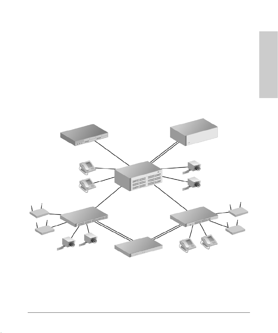
5406zl Switch
3500yl-48G-PWR
3500yl-24G-PWR
Wireless
Access
Points
Cameras
Cameras
Phones
Phones
Mitel 3300
IP PBX
Wireless
Access
Points
620 RPS/EPS
Power Supply Shelf
Overview
Power over Ethernet connections to embedded computers will allow a less
expensive installation (no AC cabling, lower labor costs), facilitate updating
the installation and repositioning of end devices (wireless access points,
security cameras, and so forth) without electricians, while maintaining full
control over every node through the internet.
Figure 1-1 shows a typical system implemented to power telephones and
wireless access points. The PoE Ethernet switches are installed to supply
power over the twisted pair LAN cables to run phones or other appliances as
required.
Figure 1-1. Example of a Typical Implementation
1-3
Page 14

Introduction
Introduction
Power Through the Cable
Here are some reasons why you might want to do this:
■ Simplifies installation and saves space - only one set of wires to bring to
your appliance.
■ Saves time and money - there is no need to pay for additional electrical
power runs or to delay your installation schedule to make them.
■ Minimal disruption to the workplace - the appliance can be easily moved,
to wherever you can lay a LAN cable.
■ Safer - no AC voltages need to be added for additional network devices.
■ As well as the data transfer to and from the appliance, you can use SNMP
network management infrastructure to monitor and control the
appliances.
■ Appliances can be shut down or reset remotely - no need for a reset button
or power switch.
■ When implementing wireless LAN systems it simplifies the radio
frequency (RF) survey task, as the access point can easily be moved and
wired in.
Power Through the Cable
A standard CAT5 Ethernet cable has four twisted pairs. Only two of these pairs
are used for 10Base-T and 100Base-TX data; all four are used for 1000Base-T
data. The specification allows two options for using these cables for power:
■ The spare pairs are used. The pair on pins 4 and 5 are connected
together and form the positive supply, and the pair on pins 7 and 8 are
connected and form the negative supply.
■ The data pairs are used. Since Ethernet pairs are transformer coupled
at each end, it is possible to apply DC power to the center tap of the
isolation transformer without upsetting the data transfer. In this mode of
operation the pair on pins 1 and 2 and the pair on pins 3 and 6 can be of
either polarity.
The 802.3af standard does not allow both pairs (spare and data) to be used a choice must be made. The Power Sourcing Equipment (PSE) applies power
to either set of wires. HP ProCurve Networking switches, as a PSE, supply
PoE power over the “data pair” or, pins 1 and 2, and the pair on pins 3 and 6.
The Powered Device (PD) must be able to accept power from both options
because mid-span equipment must (according to the specification) supply
power over the “spare pair” or pins 4 and 5, and the pair on pins 7 and 8.
1-4
Page 15

PoE Capabilities of the Products
Introduction
An obvious requirement of the specification is to prevent damage to existing
Ethernet equipment. A discovery process, run from the PSE, examines the
Ethernet cables, looking for devices that comply with the specification. It does
this by applying a small current-limited voltage to the cable and checks for the
presence of a 25k ohm resistor in the remote device. Only if the resistor is
present, will the full wattage be applied, but this is still current-limited to
prevent damage to cables and equipment in fault conditions.
Once discovered, a different voltage is applied, and based upon the current
drawn, the class of device can be determined. This indicates how much power
is to be drawn. The 802.3at standard provides both a physical classification
and a logical classification, which is even more precise.
The PD must continue to draw a minimum current. If it does not (for example,
when the device is unplugged) then the PSE removes the power and the
discovery process begins again.
Introduction
PoE Capabilities of the Products
These switches are designed to be used primarily in wiring closets directly
connected to computers, printers, and servers to provide dedicated
bandwidth to those devices. Additionally, they support the PoE standard IEEE
802.3af, and the PoE+ IEEE 802.3at standard. They can supply power over a
twisted-pair cable to power devices such as telephones, wireless access
points, IP Gateways, and audio and video remote monitoring.
The HP ProCurve PoE switch devices are multi-port switches that can be used
to build high-performance switched workgroup networks with PoE. These
switches are store-and-forward devices that offer low latency for high-speed
networking. The PoE switches are designed to support Redundant Power
Supply and Power over Ethernet (PoE and/or PoE+) technologies.
1-5
Page 16
Introduction
Introduction
PoE Capabilities of the Products
HP ProCurve 2520 Switches
The 2520 (J9137A), has 8 Integrated PoE auto-sensing 10/100Base-TX RJ-45
ports with two dual-personality Gigabit Uplink ports.
The 2520 (J9138A), has 24 Integrated PoE auto-sensing 10/100Base-TX RJ-45
ports and two 10/100/1000Base-TX uplink ports, with two dual-personality
Gigabit Uplink ports.
These switches also support some pre-standard PoE devices. For a list of these
devices, see the FAQs for your switch model. This feature must be enabled; it
is not a default feature.
The dual-personality ports have either auto-sensing 10/100/1000Base-T
RJ-45 or mini-GBIC connectivity. The dual-personality ports do not support
PoE.
1-6
Page 17
PoE Capabilities of the Products
Introduction
Introduction
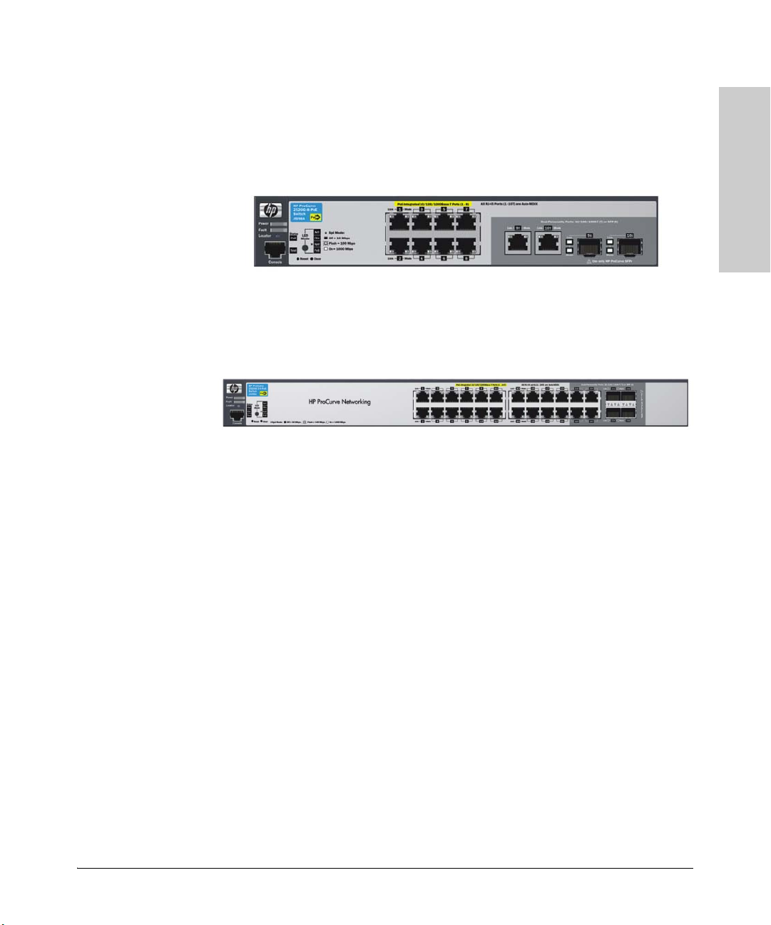
HP ProCurve 2520G Switches
The 2520G (J9298A), has 8 Integrated PoE auto-sensing 10/100/1000Base-TX
RJ-45 ports with two dual-personality Gigabit Uplink ports.
The 2520G (J9299A), has 24 Integrated PoE auto-sensing 10/100/1000Base-TX
RJ-45 ports including four dual-personality Gigabit Uplink ports.
These switches also support some pre-standard PoE devices. For a list of these
devices, see the FAQs for your switch model. This feature must be enabled; it
is not a default feature.
The dual-personality ports have either auto-sensing 10/100/1000Base-T
RJ-45 or mini-GBIC connectivity. The dual-personality ports do not support
PoE.
1-7
Page 18
Introduction
Introduction
PoE
Power
Fault
Dual-Personality Port:
10/100/1000-T (T) or Mini-GBIC (M)
(Port 9T is IEEE Auto MDI/MDIX)
Status
Reset
Clear
Console
PoE-Integrated 10/100-TX Ports (1 - 8) (Ports are HP Auto-MDIX)
ProCurve
Switch 2600-PWR
J8762A
*
Spd mode: off = 10 Mbps, flash = 100 Mbps, on = 1000 Mbps
Link
Mode
LED
Mode
Spd
Act
FDx
Test
EPS
Fan
2
3
4
Link
Mode
1
Link
Mode
5
6
7
8
9T
Link
Mode
PoE
*
9M
!
Use only one (T or M) for Port 9
RPS
PoE Capabilities of the Products
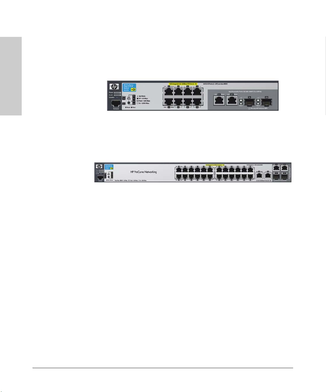
HP ProCurve 2600 Switches
The 2650-PWR (J8165A), has 48 Integrated PoE auto-sensing 10/100Base-TX
RJ-45 ports with two dual-personality Gigabit Uplink ports.
The 2626-PWR (J8164A), has 24 Integrated PoE auto-sensing 10/100Base-TX
RJ-45 ports with two dual-personality Gigabit Uplink ports.
The 2600-8-PWR with Gigabit Uplink (J8762A), has 8 Integrated PoE autosensing 10/100Base-TX RJ-45 ports with one dual-personality Gigabit Uplink
port. The 2600-8-PWR also supports some pre-standard PoE devices. For a list
of these devices, see the FAQs for your switch model. This feature must be
enabled; it is not a default feature.
The dual-personality ports have either auto-sensing 10/100/1000Base-T
RJ-45 or mini-GBIC connectivity. The dual-personality ports do not support
PoE.
1-8
Page 19
PoE Capabilities of the Products
Introduction
Introduction
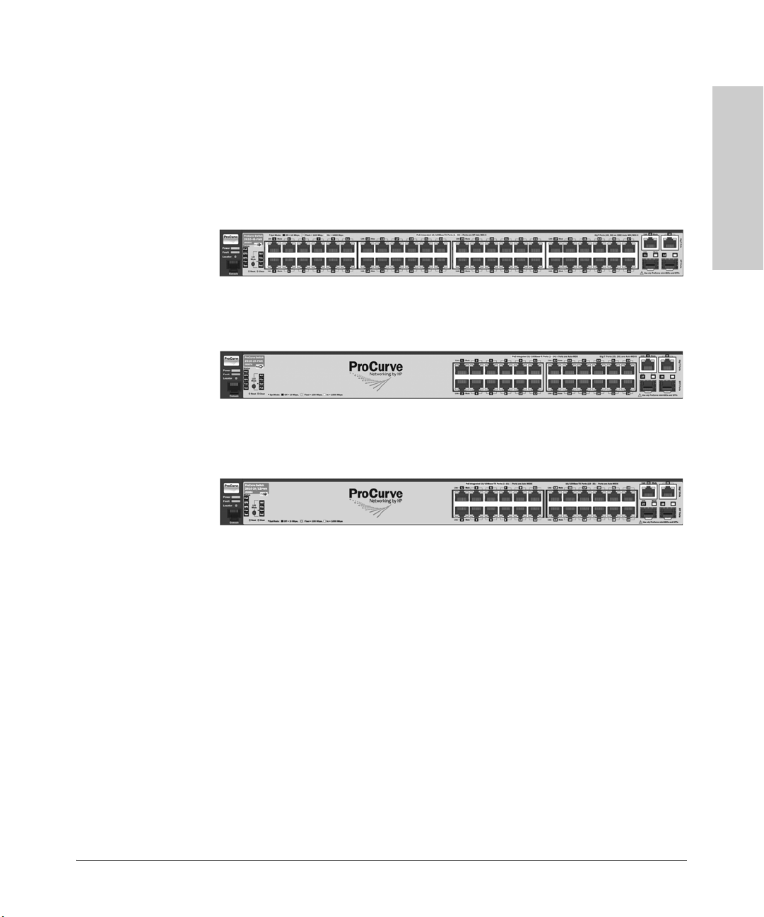
HP ProCurve 2610 Switches
These switches support some pre-standard PoE devices. For a list of these
devices, see the FAQs for your switch model. This feature must be enabled; it
is not a default feature.
The 2610-48-PWR (J9089A), has 48 Integrated PoE auto-sensing
10/100Base-TX RJ-45 ports with four Gigabit Uplink ports.
The 2610-24-PWR (J9087A), has 24 Integrated PoE auto-sensing 10/100BaseTX RJ-45 ports with four Gigabit Uplink ports.
The 2610-24/12PWR (J9086A), has 12 Integrated PoE auto-sensing 10/100BaseTX RJ-45 ports with four Gigabit Uplink ports.
For more information, refer to the Management and Configuration Guide on
the ProCurve Web site. To display the list of downloadable manuals, click on
the following link: www.hp.com/go/procurve/manuals.
(You may want to bookmark this Web page for easy access in the future.)
1-9
Page 20

Introduction
Introduction
PoE Capabilities of the Products
Power Redundancy for the 2600 and 2610 Switches
The internal power supply in these switches provides both the 12V (RPS) and
50V (EPS) circuits. If either the 12V or 50V fails, the power supply shuts down
which will bring down all switch and PoE connections. Therefore it is
important to provide a redundant power supply for both the 12V and 50V
circuits. Thus when you connect EPS from a 600 RPS/EPS device to one of
the 2600-PWR Switches or one of the 2610-PWR Switches, you should also
connect the RPS as well to provide full redundant power.
The 2600-PWR Switches and 2610-PWR Switches can be connected to a 600
RPS/EPS and receive full redundant power from the RPS part of the unit for
switch operation, if the internal power supply in the switch fails. If multiple
switches are connected to the RPS ports and several switches lose power at
the same time, the switch attached to the lowest RPS port number receives
power. The 600 RPS/EPS unit can provide all the power necessary to keep one
switch running.
EPS power from the 600 RPS/EPS is the PoE capability of the device. It
supplies backup and additional PoE power for the ports of the 2600-PWR and
2610-PWR switches.
The 610 EPS can also be used for this purpose, to supply PoE power only. The
610 EPS cannot supply RPS power, it can only supply PoE power. Refer to
chapter three, four, and five for more information on capabilities and
connectivity of these switches, components and accessories.
1-10
Page 21
PoE Capabilities of the Products
Introduction
Power
Fault
Locator
Console
LED
Mode
Clear
Reset
PoE+ Integrated 10/100/1000Base-T Ports (1 - 48T) Ports are Auto-MDIX
Test
Tmp
Status
Dual-Personality Ports: 10/100/1000-T (T) or SFP (S)
!
Use only one (T or S) for each Port
PoE
Fan
45S
47S
46S 48S
*
Spd mode: off=10 Mbps, 2 flash=100 Mbps, on=1 Gbps, 3 flash=10 Gbps
FDx
Spd
PoE
Act
*
38
40
43
41
39
37
12
10
8
6
4
2
11
9
7
5
3
1
42
44
Link
Mode
Link
Mode
Link
Mode
47T
45T
46T
48T
Link
Mode
Status of the Back
Mdl RPS
EPS
ProCurve Switch
2910bl-48G-PoE
J9148A
Link Mode
Link Mode
24
2220
18
16
14
2321
1917
1513
Link
Mode
Link
Mode
36
3432
30
28
26
3533
31
29
2725
Link
Mode
Link
Mode
Usr
PoE+
Power
Fault
Locator
Console
Spd mode: off = 10 Mbps
2 flash = 100 Mbps
on = 1 Gbps
3 flash = 10 Gbps
*
LED
Mode
Clear
Reset
PoE+ Integrated 10/100/1000Base-T Ports (1 - 24T) Ports are Auto-MDIX
Test
Tmp
Status
Dual-Personality Ports: 10/100/1000-T (T) or SFP (S)
!
Use only one (T or S) for each Port
PoE
Fan
21S
23S
22S 24S
FDx
Spd
PoE
Act
*
14
16
19
17
15
13
18
20
Link
Mode
23T
21T
22T
24T
Link
Mode
Status of the Back
Mdl
RPS
EPS
ProCurve Switch
2910bl-24G-PoE
J9146A
Link Mode
Link Mode
12
10
8
6
4
2
119
7
5
31
Link
Mode
Link
Mode
Usr
Auxiliary Port
PoE+
Introduction
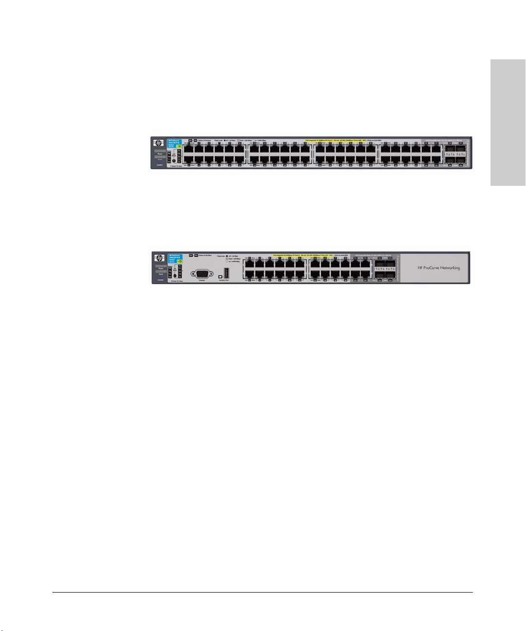
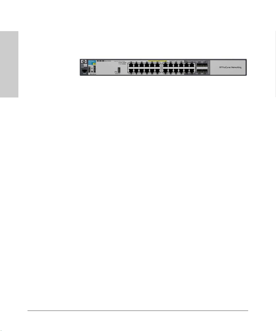
HP ProCurve 2910al Switches
The HP ProCurve Switch 2910al-48G-PoE+ (J9148A), has 44 Integrated PoE+
auto-sensing 10/100/1000Base-T RJ-45 ports with four dual-personality Gigabit
Uplink ports.
The HP ProCurve Switch 2910al-24G-PoE+ (J9146A), has 20 Integrated PoE+
auto-sensing 10/100/1000Base-T RJ-45 ports with four dual-personality Gigabit
Uplink ports.
These switches also support some pre-standard PoE devices. While HP
ProCurve strives to support as many non-standard devices as possible, some
devices in the market are designed in ways that are restrictive, or exclusive
of the IEEE standard and thus cannot be supported. For a list of these devices,
see the FAQs for your switch model, www.hp.com/go/procurve/faqs. This
feature is the default and you must disable it if you do not want to use it. For
example:
ProCurve 2910al#(config) no power pre-std-detect
For more information, refer to the Management and Configuration Guide
which is on the ProCurve Web site. To display the list of downloadable
manuals, click on the following link: www.hp.com/go/procurve/manuals.
(You may want to bookmark this Web page for easy access in the future.)
The dual-personality ports have either auto-sensing 10/100/1000Base-T RJ-45
or mini-GBIC connectivity. The mini-GBIC ports do not support PoE. If any of
the mini-GBIC ports are used the corresponding RJ-45 port will not be supplied
with PoE/PoE+ power.
1-11
Page 22

Introduction
Introduction
PoE Capabilities of the Products
Power Redundancy for the 2910al Switches
The internal power supply in these switches provides both the 12V (RPS) and
54V (EPS) circuits. If the 54V portion of the power supply fails, it will only shut
down the PoE connections. However, if the 12V portion of the power supply
fails, it will shut down the entire switch. Therefore it is important to provide
a redundant power supply for both the 12V and 54V circuits. It is recommended
that both EPS and RPS be connected to provide full redundancy.
HP ProCurve Redundant/External Power Supplies (RPS/EPS) can be
connected to the 2910al Switches for redundant 12 V system power (RPS) and
to provide for additional PoE+ provisioning. For RPS power, the 2910al
Switches can be connected to either an HP ProCurve 620 RPS/EPS or HP
ProCurve 630 RPS/EPS. For additional PoE+ EPS power, only the 630 can be
used. The 620 does not provide 54 V for PoE+, only 50 V for PoE, and the 2910al
Switches do not support connections to the 620 for EPS.
The 2910al switch provides up to 30W from each port (25.5W for PD, 4.5W for
cable dissipation); the number of ports that can be operated at full power is
limited to 12 ports at full power, and/or 24 ports at 15.4W. To increase the
capacity of the switch, an external power supply can be attached to double
the total system capacity to 24 ports at 30W, or 48 ports at 15.4W.
The power supplies for these switches are optimized to provide the most
efficient and cost effective solution.
1-12
Page 23
PoE Capabilities of the Products
Introduction
Introduction
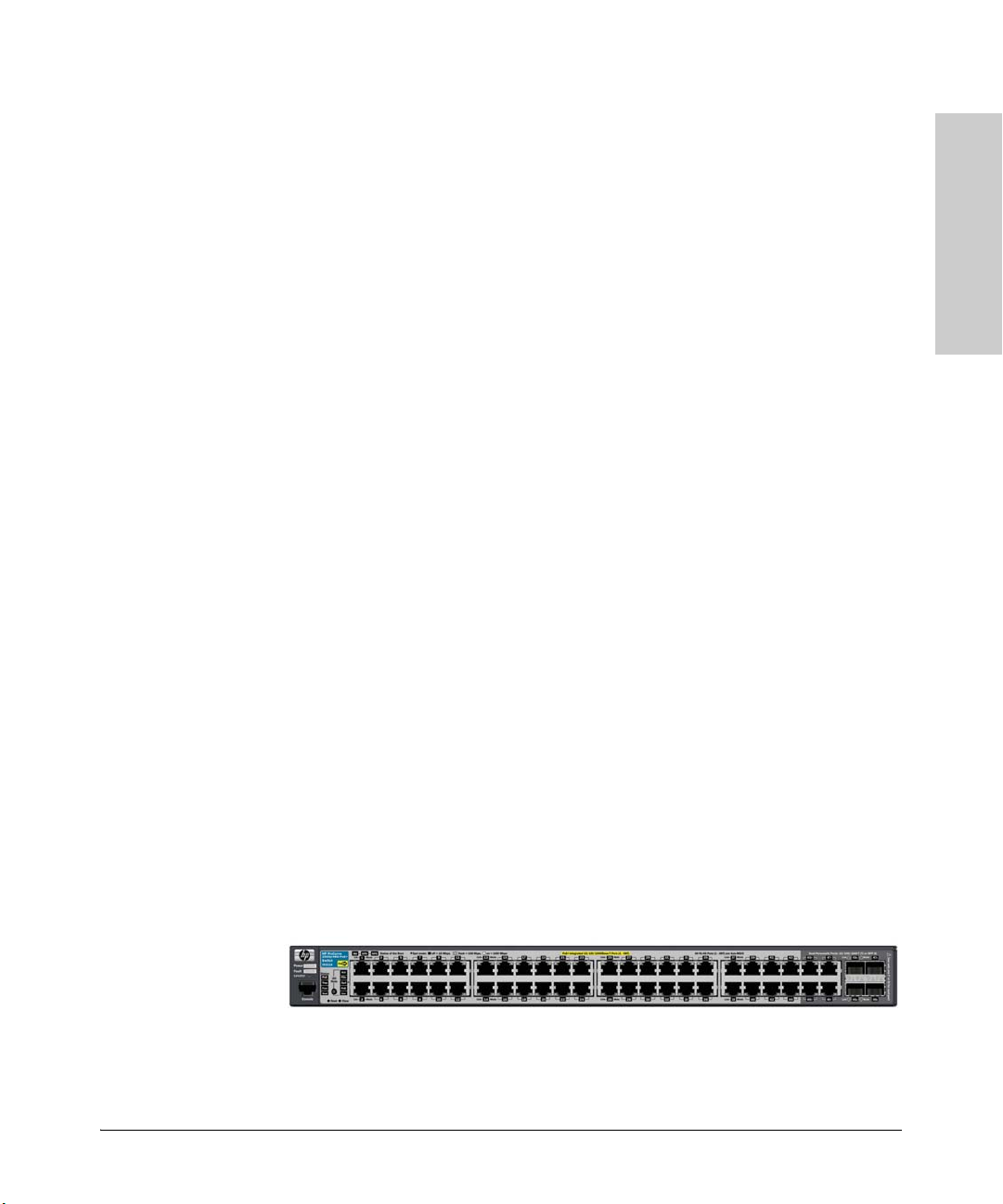
HP ProCurve 3500-PoE Switches
The HP ProCurve Switch 3500-48G-PoE (J9473A), has 44 Integrated PoE autosensing 10/100 Base-T RJ-45 ports and four ports of Gigabit dual-personality
Uplink ports, either RJ-45 or SFP.
The HP ProCurve Switch 3500-24G-PoE (J9471A), has 20 Integrated PoE autosensing 10/100 Base-T RJ-45 ports with four ports of Gigabit dual-personality
Uplink ports, either RJ-45 or SFP.
These switches also support some pre-standard PoE devices. For a list of these
devices, see the FAQs for your switch model. This feature is the default and
you must disable it if you do not want to use it. For example:
ProCurve(config# no power pre-std-detect
For more information, refer to the Management and Configuration Guide
which is on the ProCurve Web site. To display the list of downloadable
manuals, click on the following link: www.hp.com/go/procurve/manuals.
(You may want to bookmark this Web page for easy access in the future.)
The dual-personality ports have either auto-sensing 10/100 Base-T RJ-45 or
mini-GBIC connectivity. The mini-GBIC ports do not support PoE. If any of
the mini-GBIC ports are used the corresponding RJ-45 port will not be supplied
with PoE power.
1-13
Page 24

Introduction
Introduction
PoE Capabilities of the Products
Power Redundancy for the 3500 Switches
The internal power supply in these switches provides both the 12V (RPS) and
50V (EPS) circuits. If the 50V portion of the power supply fails, it will only shut
down the PoE connections. However, if the 12V portion of the power supply
fails, it will shut down the entire switch. Therefore it is important to provide
a redundant power supply for both the 12V and 50V circuits. It is recommended
that both EPS and RPS be connected to provide full redundancy.
The HP ProCurve 3500-PoE Switches can be connected to a 620 RPS/EPS and
receive full redundant power from the RPS part of the unit for switch operation
if the internal power supply in the switch fails. If two switches are connected
to the RPS ports and both switches lose power at the same time, they both
receive redundant power. The 620 RPS/EPS unit can provide all the power
necessary to keep two switches running.
If maximum PoE power is to be used on all 48 ports, you must connect an HP
ProCurve 620 RPS/EPS, since the internal power supply only has enough
power to supply 24 ports with maximum wattage. In this case, there is no
redundancy.
HP ProCurve 3500yl-PWR Switches
The HP ProCurve Switch 3500yl-48G-PWR (J8693A), has 44 Integrated PoE
auto-sensing 10/100/1000Base-T RJ-45 ports with four dual-personality Gigabit
Uplink ports.
The HP ProCurve Switch 3500yl-24G-PWR (J8692A), has 20 Integrated PoE
auto-sensing 10/100/1000Base-T RJ-45 ports with four dual-personality Gigabit
Uplink ports.
These switches also support some pre-standard PoE devices. For a list of these
devices, see the FAQs for your switch model. This feature is the default and
you must disable it if you do not want to use it. For example:
ProCurve(config)# no power pre-std-detect
1-14
Page 25
PoE Capabilities of the Products
Introduction
For more information, refer to the Management and Configuration Guide
which is on the ProCurve Web site. To display the list of downloadable
manuals, click on the following link: www.hp.com/go/procurve/manuals.
(You may want to bookmark this Web page for easy access in the future.)
The dual-personality ports have either auto-sensing 10/100/1000Base-T RJ-45
or mini-GBIC connectivity. The mini-GBIC ports do not support PoE. If any of
the mini-GBIC ports are used the corresponding RJ-45 port will not be supplied
with PoE power.
Introduction
Power Redundancy for the 3500yl PWR Switches
The internal power supply in these switches provides both the 12V (RPS) and
50V (EPS) circuits. If the 50V portion of the power supply fails, it will only shut
down the PoE connections. However, if the 12V portion of the power supply
fails, it will shut down the entire switch. Therefore it is important to provide
a redundant power supply for both the 12V and 50V circuits. It is recommended
that both EPS and RPS be connected to provide full redundancy.
The 3500yl-PWR Switches can be connected to a 620 RPS/EPS and receive full
redundant power from the RPS part of the unit for switch operation if the
internal power supply in the switch fails. If two switches are connected to the
RPS ports and both switches lose power at the same time, they both receive
redundant power. The 620 RPS/EPS unit can provide all the power necessary
to keep two switches running.
If maximum PoE power is to be used on all 48 ports, it becomes necessary to
connect a 620 RPS/EPS, since the internal power supply only has enough
power to supply 24 ports with maximum wattage. In this case, there is no
redundancy.
HP ProCurve 3500yl-PoE+ Switches
The HP ProCurve Switch 3500yl-48G-PoE+ (J9311A), has 44 Integrated PoE
auto-sensing 10/100/1000Base-T RJ-45 ports with four dual-personality Gigabit
Uplink ports.
1-15
Page 26
Introduction
Introduction
PoE Capabilities of the Products
The HP ProCurve Switch 3500yl-24G-PoE+ (J9310A), has 20 Integrated PoE
auto-sensing 10/100/1000Base-T RJ-45 ports with four dual-personality Gigabit
Uplink ports.
These switches also support some pre-standard PoE devices. For a list of these
devices, see the FAQs for your switch model. This feature is the default and
you must disable it if you do not want to use it. For example:
For more information, refer to the Management and Configuration Guide
which is on the ProCurve Web site. To display the list of downloadable
manuals, click on the following link: www.hp.com/go/procurve/manuals.
(You may want to bookmark this Web page for easy access in the future.)
The dual-personality ports have either auto-sensing 10/100/1000Base-T RJ-45
or mini-GBIC connectivity. The mini-GBIC ports do not support PoE. If any of
the mini-GBIC ports are used the corresponding RJ-45 port will not be supplied
with PoE power.
ProCurve(config)# no power pre-std-detect
Power Redundancy for the 3500yl PoE+ Switches
The internal power supply in these switches provides both the 12V (RPS) and
54V (EPS) circuits. If the 54V portion of the power supply fails, it will only shut
down the PoE connections. However, if the 12V portion of the power supply
fails, it will shut down the entire switch. Therefore it is important to provide
a redundant power supply for both the 12V and 54V circuits. It is recommended
that both EPS and RPS be connected to provide full redundancy.
The 3500yl-PoE+ Switches can be connected to an HP ProCurve 630 RPS/EPS
and receive full redundant power from the RPS part of the unit for switch
operation if the internal power supply in the switch fails. The HP ProCurve
630 RPS/EPS unit can provide all the power necessary to keep only one switch
running.
The "maximum PoE+" power for 48 ports equals (48 ports x 30 watts = 1440
watts). The 398 watts of internal power plus the 382 watts from the EPS equals
780 watts. This will only support "maximum PoE+" power on 24 of the 48 ports.
The internal power supply can only support "maximum PoE+" on 12 of 48 ports
(or 12 of 24 ports on 24 port PoE+ switch).
1-16
Page 27
PoE Capabilities of the Products
Introduction
Introduction
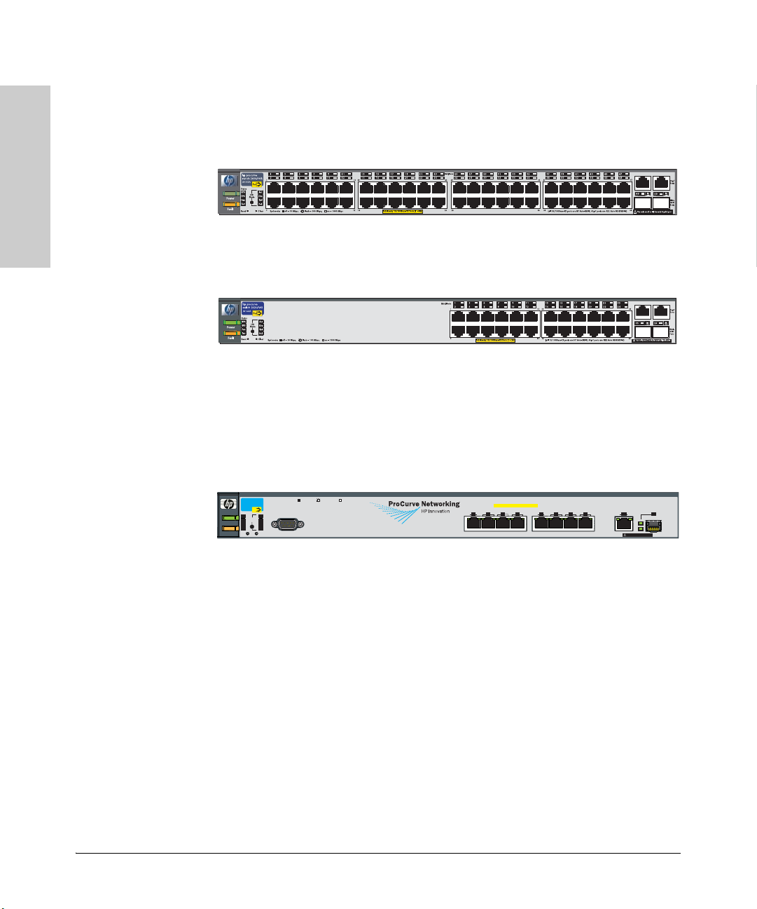
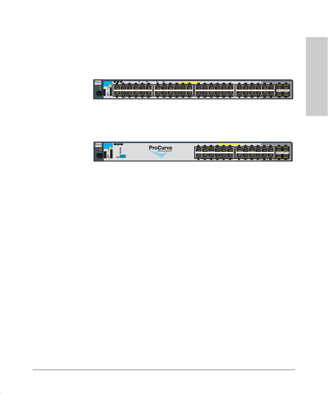
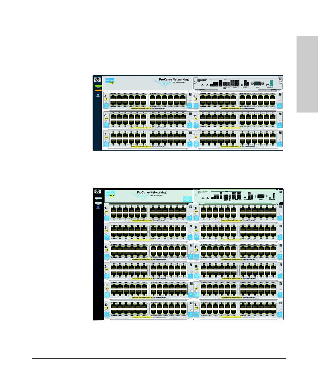
HP ProCurve 5400zl/8200zl Switches
The HP ProCurve Switch 5406zl is a chassis that can hold up to six 24-port
modules to provide up to 144 10/100/1000Base-T RJ-45 ports for PoE/PoE+
power.
The HP ProCurve Switch 5412zl is a chassis that can hold up to twelve 24-port
modules to provide up to 288 10/100/1000Base-T RJ-45 ports for PoE/PoE+
power.
1-17
Page 28
Introduction
Introduction
PoE Capabilities of the Products
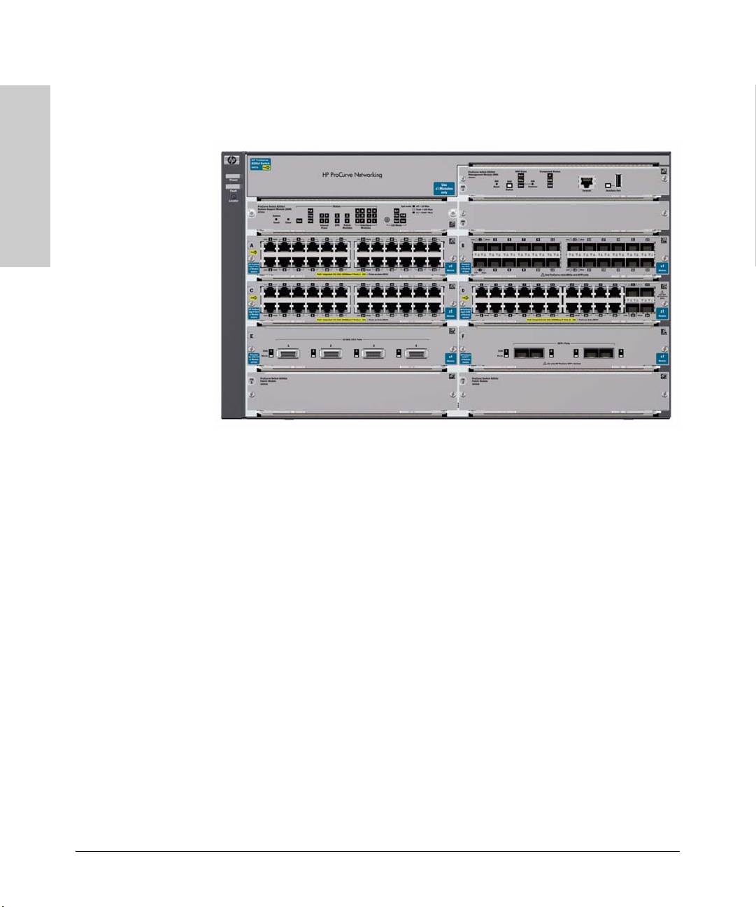
The HP ProCurve Switch 8206zl is a chassis that can hold up to six 24-port
modules to provide up to 144 10/100/1000Base-T RJ-45 ports for PoE/PoE+
power.
1-18
Page 29
PoE Capabilities of the Products
Introduction
Introduction
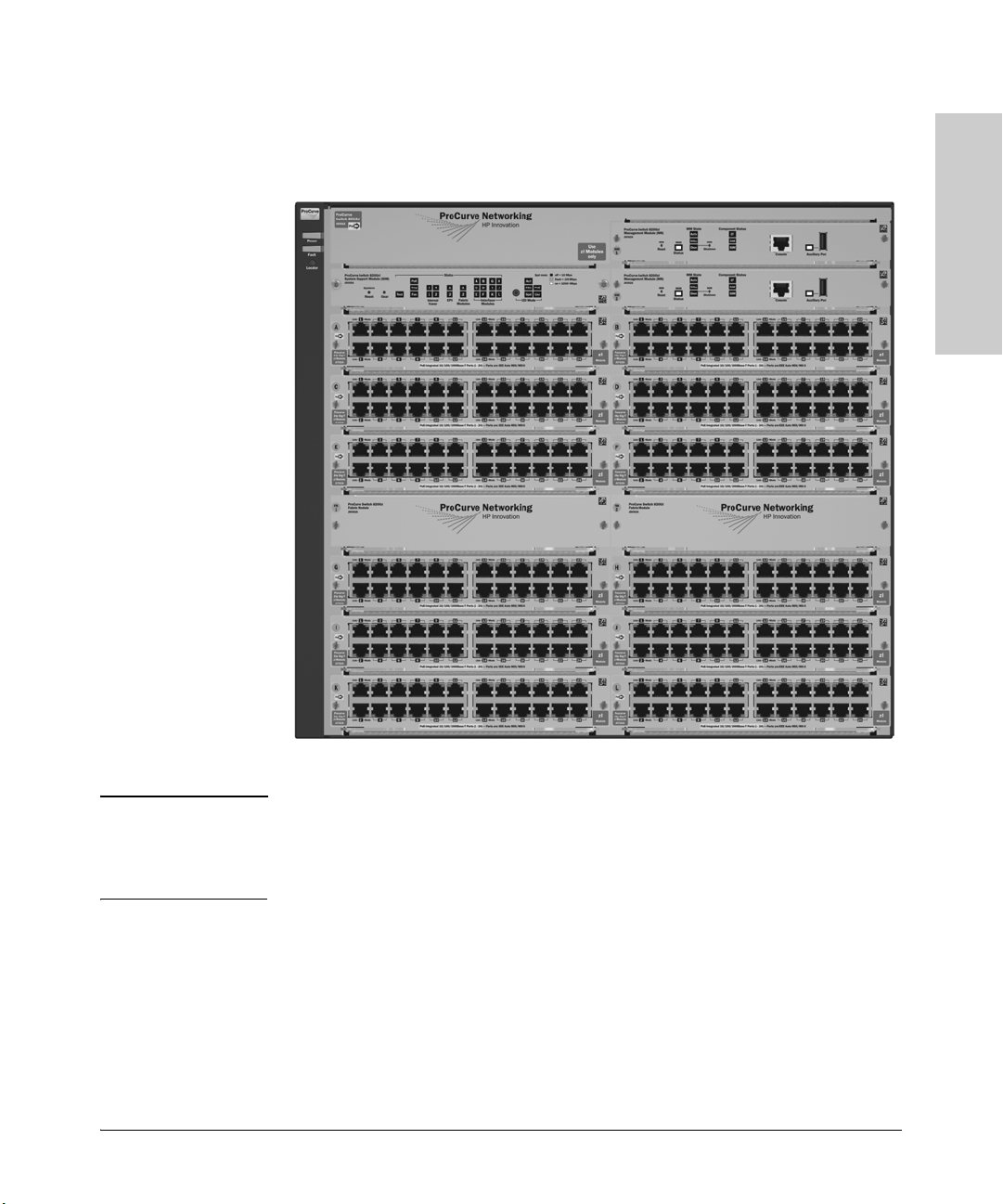
The HP ProCurve Switch 8212zl is a chassis that can hold up to twelve 24-port
modules to provide up to 288 10/100/1000Base-T RJ-45 ports for PoE/PoE+
power.
Note The 5412zl chassis and the 8212zl chassis share a completely common
PoE/PoE+ implementation. Port counts, power supply wattages,
specifications, and functionality for these two platforms are the same with
respect to PoE/PoE+.
Power Redundancy for the5400zl/8200zl Switches
There are three types of power supplied by the Series 5400zl/8200zl switch
power supplies:
■ 12V power or system power
■ 50V power for PoE power
■ 54V power for PoE/PoE+ power
1-19
Page 30

Introduction
Introduction
PoE Capabilities of the Products
The 12V system power is used to operate the internal components of the
switch. The 50V PoE or 54V PoE/PoE+ power is used to power the PoE devices
connected to the modules.
It is important to provide a secondary power supply for redundancy purposes
for both the 12V and 50V or 54V circuits. The internal power supply in these
switches provides both the 12V (system) and 50V (PoE) or 54V (PoE+)
circuits. If the 12V (system) power fails the switch will shut down. If the 50V
or 54V fails, all PDs would lose power. Therefore, to keep the switch running
should one power supply, or either power source fail, you should install a
second power supply.
The 5406zl/8206zl chassis can hold two internal power supplies and the
5412zl/8212zl chassis can hold four internal power supplies.
PoE/PoE+ Power Supplies
Why Mixing Power Supplies is NOT Supported
Using a combination of zl PoE power supplies J8712A and J8713A and a J9306A
zl power supply in PoE/PoE+ systems is NOT supported. Use the J9306A zl
power supply for systems providing PoE and PoE+ power.
The reason the power supplies should not be mixed is because the J8712A and
J8713A power supplies provide PoE power at 50 volts (273 watts for J8712A
and 900 watts for J8713A). The J9306A zl power supply provides PoE/PoE+
power at 54 volts (300 watts at 110 volts and 900 watts at 220 volts). If you
install a J8712A or J8713A with a J9306A power supply, they do voltage sharing.
This means that the 54 volts of the J9306A zl power supply will supersede the
50 volts of the J8712A or J8713A power supplies. Only the J9306A will provide
PoE/PoE+ power.
For example, if an HP ProCurve 5406zl switch on a 110 volt circuit has a J8712A
installed, and then a J9306A is inserted, the switch only provides 300 watts of
power, not 573 watts (273 watts + 300 watts). Only the J9306A provides PoE/
PoE+ power, which is 300 watts.
In another example, if an HP ProCurve 8212zl switch on a 220 volt circuit has
three J8713A power supplies installed, and then a J9306A is inserted, the
switch only provides 900 watts of PoE/PoE+ power, not 3600 watts (2700 watts
from the three J8713A power supplies and 900 watts from the J9306A power
supply). Only the J9306A will provide PoE/PoE+ power.
1-20
Page 31

PoE Capabilities of the Products
Introduction
Introduction
PoE Power Supplies
Note HP ProCurve Networking highly recommends that the two types of power
supplies are not mixed in the same chassis.
For PoE only, the following power supplies can be used:
■ J8712A, which operates at 100-127 volts drawing a maximum of 11.5 amps,
or 200-240 volts drawing a maximum of 5.7 amps, and supplies 273 watts
of PoE power
■ J8713A, which operates at 200-220 volts drawing a maximum of 10 amps,
and supplies 900 watts of PoE power
Using two J8712As, or two J8713As, or a mix of both is supported (however
mixing power supplies is not recommended, see page 10-7 for more
information) and necessary to ensure the switch has both 12V (system power)
and 50V (PoE power) should one power supply fail. See the HP ProCurve
Switch zl Internal Power Supplies Installation Guide, for more information
and specifications on these power supplies.
When considering redundant power, also consider the power source for the
power supplies. Each power supply should be connected to a separate power
source circuit in order to supply complete redundancy. Should one circuit fail,
it would then be possible for the other circuit to continue supplying power to
the second power supply in the switch, keeping the switch running.
There is also an external power supply, the HP ProCurve Switch zl Power
Supply Shelf (J8714A), that can be connected to either the 5400zl switches or
the 8200zl switch for the purpose of adding extra or backup 50V (PoE power).
The zl Power Supply Shelf will not supply any 12V (system power) to any zl
switch, since the switch is provided with 12V redundancy when more than one
power supply is installed in the chassis.
PoE/PoE+ Power Supply
For PoE or PoE+, the J9306A power supply can be used. This power supply
operates at 110-127V providing 300 watts of PoE/PoE+ power, or 200-240V
providing 900 watts of PoE/PoE+ power. See the HP ProCurve Switch zl
Internal Power Supplies Installation Guide for more information and
specifications on this power supply.
There is also an external power supply, the HP ProCurve Switch zl Power
Supply Shelf (J8714A), that can be connected to either the 5400zl switches or
the 8200zl switches to add extra or backup 54V (PoE/PoE+) power. The zl
Power Supply Shelf will not supply any 12V (system power) to any zl switch,
since the switch is provided with 12V redundancy when more than one power
supply is installed in the chassis.
1-21
Page 32

Introduction
Introduction
PoE Capabilities of the Products
Configuring PoE Redundancy
When considering redundant power, also consider the power source for the
power supplies. Each power supply should be connected to a separate power
source circuit in order to supply complete redundancy. Should one circuit fail,
it would then be possible for the other circuit to continue supplying power to
the second power supply in the switch, keeping the switch running.
When PoE redundancy is enabled, PoE redundancy occurs automatically. The
switch keeps track of power use and won’t supply PoE power to additional
PoE devices trying to connect if that results in the switch not having enough
power in reserve for redundancy if one of the power supplies should fail. There
are three configurable redundancy methods:
■ No PoE redundancy enforcement (default). All available power can be
■ Full redundancy: half of the totally available PoE power can be allocated
■ N+1. One of the power supplies is held in reserve for redundancy. If a
allocated.
and half is held in reserve for redundancy. If power supplies with different
ratings are used, the highest-rated power supply is held in reserve to
ensure full redundancy.
single power supply fails, no powered devices are shut down. If power
supplies with different ratings are used, the highest-rated power supply is
held in reserve to ensure full redundancy.
Note When changing from one method to another, always check the current level
of PoE usage before implementing the change. The change could cause
existing connection to lose PoE power.
When considering redundant power, also consider the power source for the
power supplies. Each power supply should be connected to a separate power
source circuit in order to supply complete redundancy. Should one circuit fail,
it would then be possible for the other circuit to continue supplying power to
the second power supply in the switch, keeping the switch running.
1-22
Page 33

HP ProCurve PoE and PoE+ Modules
Introduction
Std PoE
PoE
EPS
Status
LED Mode
Link
Mode
Link
Mode
1
2
3
4
5
6
13 14
15
16
17 18
23
2221
20
19
12
11
10
9
8
7
PoE-Ready 10/100-TX Ports (1-24) all ports are HP Auto-MDIX
24
hp procurve
PoE
xl module
J8161A
xl
module
PoE
Introduction
HP ProCurve PoE and PoE+ Modules
HP ProCurve Switch xl PoE Module
The HP ProCurve Switch xl PoE Module (J8161A) is a module for the HP
ProCurve 5300xl Switch and has 24 PoE-ready auto-sensing 10/100-TX RJ-45
ports.
All 24 ports are capable of supplying PoE power. However, for the module
ports to be able to supply PoE power it first must be connected to an EPS port
on a HP ProCurve 600 Redundant and External Power Supply (J8168A), or the
HP ProCurve 610 External Power Supply (J8169A), hereafter referred to as
the 600 RPS/EPS or the 610 EPS, respectively.
ProCurve Switch zl 24 port Gig-T PoE Module (J8702A)
The ProCurve Switch zl 24 port PoE Module (J8702A) is for the HP ProCurve
5400/8200zl switches and has 24 PoE auto-sensing 10/100/1000-TX RJ-45 ports.
All 24 ports are capable of supplying PoE power.
1-23
Page 34

Introduction
Introduction
HP ProCurve PoE and PoE+ Modules
ProCurve Switch zl 20 port Gig-T + 4 port mGBIC Module (J8705A)
The ProCurve Switch zl 20 port Gig-T + 4 port mGBIC Module (J8705A) is for
the HP ProCurve 5400/8200zl switches and has 20 PoE auto-sensing 10/100/
1000-TX RJ-45 ports. All 20 ports are capable of supplying PoE power.
Additionally there are four mini-GBIC/SFP ports, which do not supply PoE
power.
HP ProCurve 24-Port 10/100/1000 PoE+ zl Module (J9307A)
The HP ProCurve Switch zl PoE/PoE+ Module (J9307A) is for the HP ProCurve
5400/8200zl switches and has 24 PoE/PoE+ auto-sensing 10/100/1000-TX
RJ-45 ports. All 24 ports are capable of supplying PoE/PoE+ power.
1-24
Page 35

HP ProCurve PoE and PoE+ Modules
Introduction
Introduction
HP ProCurve 20-Port 10/100/1000 PoE+/4 Port MiniGBIC zl Module (J9308A)
The HP ProCurve Switch zl PoE/PoE+ 20-port module (J9308A) is a module
for the HP ProCurve 5400/8200zl switches and has 20 PoE/PoE+ auto-sensing
10/100/1000-TX RJ-45 ports capable of supplying PoE/PoE+ power.
Additionally there are four mini-GBIC/SFP ports, which do not supply PoE/
PoE+ power.
HP ProCurve 24-Port 10/100 PoE+ zl Module (J9478A)
The HP ProCurve Switch zl PoE/PoE+ 24-port module (J9478A) is for the HP
ProCurve 5400/8200zl switches and has 24 PoE/PoE+ auto-sensing 10/100-TX
RJ-45 ports capable of providing PoE/PoE+ power.
1-25
Page 36

Introduction
Introduction
PoE
wer
ult
Dual-Personality Port:
10/100/1000-T (T) or Mini-GBIC (M)
(Port 9T is IEEE Auto MDI/MDIX)
Status
Reset
Clear
Console
PoE-Integrated 10/100-TX Ports (1 - 8) (Ports are HP Auto-MDIX)
ProCurve
Switch 2600-PWR
J8762A
*
Spd mode: off = 10 Mbps, flash = 100 Mbps, on = 1000 Mbps
Link
Mode
LED
Mode
Spd
Act
FDx
Test
EPS
Fan
2
3
4
Link
Mode
1
Link
Mode
5
6
7
8
9T
Link
Mode
PoE
*
9M
!
Use only one (T or M) for Port 9
RPS
Quick Reference Table
Quick Reference Table
Model/
Device
Stackable Switches:
2520-8-PoE
2520-24-PoE
2520G-8-PoE
2520G-24-PoE
2600-8-PWR
Port Type Port Count/
PoE watts per
1
port
10/100 8
4 @ 15.4 watts
8 @ 7.5 watts
10/100 24
12 @ 15.4 watts
24 @ 7.5 watts
10/100/1000 8
4 @ 15.4 watts
8 @ 7.5 watts
10/100/1000 24
12 @ 15.4 watts
24 @ 7.5 watts
10/100 8
8 @ 15.4 watts
Gig Uplink
Ports
2
2
4
2 - RJ45 only
2
2
2
2
2
4
2
1
RPS/EPS Maximum Power
Internal and
External
N/A 67 watts available
to ports 1-8,
provided by the
internal source.
N/A 195 watts
N/A 67 watts available
N/A 195 watts
J8168A
J8169A
available to ports
1-8, provided by
the internal
source.
to ports 1-8,
provided by the
internal source.
available to ports
1-8, provided by
the internal
source.
126 watts
available to ports
1-8, provided by
the internal
source. 408/204
watts available,
provided by the
EPS source.
4
2626-PWR
10/100 24
24 @ 15.4 watts
2
2
J8168A
J8169A
Redundant 408/
2044 watts
available to ports
1-24. Only if the
internal power
supply fails.
1-26
Page 37

Quick Reference Table
Introduction
Power
Fault
Locator
Console
Spd mode: off = 10 Mbps
2 flash = 100 Mbps
on = 1 Gbps
3 flash = 10 Gbps
*
LED
Mode
Clear
Reset
PoE+ Integrated 10/100/1000Base-T Ports (1 - 24T) Ports are Auto-MDIX
Test
Tmp
Status
Dual-Personality Ports: 10/100/1000-T (T) or SFP (S)
!
Use only one (T or S) for each Port
PoE
Fan
21S
23S
22S 24S
FDx
Spd
PoE
Act
*
14
16
19
17
15
13
18
20
Link
Mode
23T
21T
22T
24T
Link
Mode
Status of the Back
Mdl RPS
EPS
ProCurve Switch
2910bl-24G-PoE
J9146A
Link
Mode
Link Mode
12
10
8
6
4
2
119
7
5
31
Link
Mode
Link
Mode
Usr
Auxiliary Port
PoE+
Introduction
Model/
Device
Port Type Port Count/
PoE watts per
1
port
2650-PWR
10/100 48
24 @ 15.4 watts
48 @ 15.4 watts
2610-24/12-PWR 10/100 8 @ 15.4 watts
12 @ 10.5 watts
2610-24-PWR 10/100 24
24 @ 15.4 watts
Gig Uplink
Ports
2
2
4 J8168A
4 J8168A
RPS/EPS Maximum Power
Internal and
External
406 watts
J8168A
J8169A
J8169A
J8169A
available to ports
1-24, provided by
the internal
source. 408/204
watts available to
ports 25-48,
provided by the
EPS source.
126 watts
available to ports
1-12, provided by
the internal
source. 408/204
watts available,
provided by the
EPS source.
406 watts
available to ports
1-24, provided by
the internal
source. 408/204
watts available,
provided by the
EPS source.
4
4
4
2610-48-PWR 10/100 48
48 @ 15.4 watts
4 J8168A
J8169A
406 watts
available to ports
1-24, provided by
the internal
source. 408/204
4
watts available to
ports 25-48,
provided by the
EPS source.
2910al-24G-PoE
10/100/10002424 @ 30 watts
5
2
4
J9146A
382 watts available
to ports 1-24,
provided by the
internal source. 770
watts available,
provided by the EPS
source.
1-27
Page 38

Introduction
Introduction
Power
Fault
Locator
Console
LED
Mode
Clear
Reset
PoE+ Integrated 10/100/1000Base-T Ports (1 - 48T) Ports are Auto-MDIX
Test
Tmp
Status
Dual-Personality Ports: 10/100/1000-T (T) or SFP (S)
!
Use only one (T or S) for each Port
PoE
Fan
45S
47S
46S 48S
*
Spd mode: off=10 Mbps, 2 flash=100 Mbps, on=1 Gbps, 3 flash=10 Gbps
FDx
Spd
PoE
Act
*
38
40
43
41
39
37
12
10
8
6
4
2
11
9
7
5
3
1
42
44
Link
Mode
Link
Mode
Link
Mode
47T
45T
46T 48T
Link
Mode
Status of the Back
Mdl
RPS
EPS
ProCurve Switch
2910bl-48G-PoE
J9148A
Link Mode
Link
Mode
24
22
20
18
16
14
23
21
19
171513
Link
Mode
Link
Mode
36
34
32
30
28
26
3533
31
29
27
25
Link
Mode
Link
Mode
Usr
PoE+
Quick Reference Table
Model/
Device
Port Type Port Count/
PoE watts per
port
2910al-48G-PoE 10/100/1000 48
24 @ 30 watts
48 @ 15 watts
3500-24-PoE
10/100
3500-48-PoE 10/100 48
3500yl-24G-PWR
10/100/10002424 @ 15.4 watts 4
3500yl-48G-PWR 10/100/1000 48
24
24 @ 15.4 watts 4
48 @ 15.4 watts
24 @ 15.4 watts
48 @ 7.5 watts
Gig Uplink
Ports
1
2
5
4
RPS/EPS Maximum Power
Internal and
External
J9148A 382 watts available
to ports 1-48,
provided by the
internal source. 770
watts available,
provided by the EPS
source.
2
J8696A
398 watts available
to ports 1-24,
provided by the
internal source. 388
watts available as
backup in case of
failure, provided by
the external source.
2
4
J8696A 786 watts available
to ports 1-48,
provided by both the
internal and external
sources.
2
J8696A
398 watts available
to ports 1-24,
provided by the
internal source. 388
watts available as
backup in case of
failure, provided by
the external source.
2
4
J8696A 786 watts available
to ports 1-48,
provided by both the
internal and external
sources.
1-28
Page 39

Quick Reference Table
Introduction
Introduction
Model/
Device
3500yl-24G-PoE+
3500yl-48G-PoE+
Port Type Port Count/
PoE watts per
1
port
10/100/10002424 @ 15.4 watts
24 @ 30 watts
10/100/10004848 @ 15.4 watts
26 @ 30 watts
Chassis Switches:
5406zl 10/100/1000 Depends on
which modules
and how many
modules. Rang e
of 24-144
Gig Uplink
Ports
2
4
2
4
Depends on
which modules
and how many
modules. Range
of 4-24
RPS/EPS Maximum Power
Internal and
External
J9310A 780 watts available
to ports 1-24,
provided by both the
internal and external
sources.
J9311A 780 watts available
to ports 1-48,
provided by both the
internal and external
sources.
J8714A A maximum of 2
internal power
supplies up to 1800
watts and the
external source can
provide up to 1800
watts depending on
which power
supplies are
installed.
8206zl 10/100/1000 Depends on
which modules
and how many
modules. Rang e
of 24-144
5412zl 10/100/1000 Depends on
which modules
and how many
modules. Rang e
of 24-288
Depends on
which modules
and how many
modules. Range of
4-24
Depends on
which modules
and how many
modules. Range
of 4-48
J9306A A maximum of 2
internal power
supplies up to 1800
watts and the
external source can
provide up to 1800
watts.
J8714A A maximum of 4
internal power
supplies up to 3600
watts and the
external source can
provide up to 1800
watts depending on
which power
supplies are
installed.
1-29
Page 40

Model/
Std PoE
PoE
EPS
Status
LED Mode
Link
Mode
Link
Mode
1
2
3
4
5
6
13 14
15
16
17 18
23
2221
20
19
12
11
10
9
8
7
PoE-Ready 10/100-TX Ports (1-24) all ports are HP Auto-MDIX
24
hp procurve
PoE
xl module
J8161A
xl
module
PoE
Device
Port Type Port Count/
PoE watts per
1
port
Gig Uplink
Ports
RPS/EPS Maximum Power
Internal and
External
8212zl
Modules:
xl PoE Module
zl 24 port Gig-T PoE
Module (J8702A)
zl 20 port Gig-T + 4 port
mGBIC Module (J8705A)
10/100/1000 Depends on
which modules
and how many
modules. Rang e
of 24-288
10/100 24
3
24 @ 15.4 watts
10/100/1000 24
24 @ 15.4 watts
10/100/1000 20
20 @ 15.4 watts
Depends on
which modules
and how many
modules. Range
of 4-48
J8714A A maximum of 4
internal power
supplies up to 3600
watts and the
external source can
provide up to 1800
watts depending on
which power
supplies are
0 J8168A
J8169A
408/204
available to ports
0 Depends on voltage
(100-127 or 200-240)
0-4 Depends on voltage
(100-127 or 200-240)
installed.
4
watts
1-24.
zl PoE+ 24-Port Module
(J9307A)
zl PoE+ 20-Port Module
(J9308A)
10/100/1000 24 up to 30
watts@ 200-
240v
10/100/1000 20 up to 30
watts@ 200-
240v
0 J9306A Depends on voltage
(100-127 or 200-240)
and if using PoE or
PoE+
0-4 J9306A Depends on voltage
(100-127 or 200-240)
and if using PoE or
PoE+
Page 41

Quick Reference Table
Introduction
Introduction
Model/
Device
zl PoE/PoE+ 24-Port
Module (J9478A)
1
Redundant power and extra PoE power can be added by connecting a Redundant and external power supply.
2
The uplink ports on this switch are dual-personality. If the RJ-45 port is used the mini-GBIC port is disabled.
3
The PoE power for this module must come from an external power supply, it does not have any internal PoE power.
4
The wattage available to each switch depends on the number of switches connected to the EPS.
5
An EPS is required for extra PoE+ power to get 24 ports at 30 watts or 48 ports at 15.4 watts.
Port Type Port Count/
PoE watts per
1
port
10/100 24 up to 30
watts@ 200-
240v
Gig Uplink
Ports
RPS/EPS Maximum Power
Internal and
External
0 J9306A Depends on voltage
(100-127 or 200-240)
and if using PoE or
PoE+
1-31
Page 42

Page 43

Operating Rules
Operating Rules
This chapter discusses the operating rules and characteristics of the HP
ProCurve product capabilities, switches and external power supplies. The
following products are discussed:
■ The HP ProCurve 2520-PoE Switches
■ The HP ProCurve 2520G-PoE Switches
■ The HP ProCurve 2600-PWR Switches
■ The HP ProCurve 2610-PWR Switches
■ The HP ProCurve Redundant and External Power Supplies: 600 RPS/EPS
and 610 EPS
■ The HP ProCurve 1500 W zl PoE+ Power Supply
■ The HP ProCurve 2910al-PoE+ Switches
■ The HP ProCurve 3500-PoE Switches
■ The HP ProCurve 3500yl-PWR Switches
■ The HP ProCurve 3500yl-PoE+ Switches
■ The HP ProCurve External and Redundant Power Supply, 620 RPS/EPS
■ The HP ProCurve 5400/8200zl Switches
■ The HP ProCurve Power Supply Shelf
■ The HP ProCurve Redundant and/or External Power Supply, 630 RPS/EPS
2
2-1
Page 44

Operating Rules
Operating Rules
Overview of Switch PoE Operation
Overview of Switch PoE Operation
■ The Switch 2520-8-PoE provisions (allocates power to) ports 1-8 with 128
■ The Switch 2520G-8-PoE provisions ports 1-8 with 128 watts of power for
■ The Switch 2626-PWR provisions ports 1-24 with 406 watts of power for
■ The Switch 2610-24/12PWR provisions ports 1-12 with 126 watts of power
■ The Switch 2910al-24G-PoE+ can supply up to 382 watts of PoE+ power
■ The Switch 3500-24-PoE can supply up to 398watts of PoE power across
■ The Switch 3500yl-24G-PWR can supply up to 398 watts of PoE/PoE+
■ The Switch 3500yl-24G-PoE+ can supply up to 398 watts of PoE/PoE+
■ The 5406zl/8206zl switches can supply up to 1800 watts of PoE/PoE+
■ The 5412zl/8212zl switches can supply up to 3600 watts of PoE/PoE+
■ The J8712A power supply provides up to 273 watts of PoE power. If two
watts of power for PoE applications compatibale with the IEEE 802.3af
standard. The Switch 2520-24-PoE provisions ports 1-24 with 384 watts of
power for PoE applications compatibale with the IEEE 802.3af standard.
PoE applications compatibale with the IEEE 802.3af standard. The Switch
2520G-24-PoE provisions ports 1-24 with 384 watts of power for PoE
applications compatibale with the IEEE 802.3af standard.
PoE applications compatible with the IEEE 802.3af standard. The Switch
2650-PWR provisions ports 1-48 with 406 watts. This reduces the per port
wattage by half as compared to the Switch 2626-PWR.
for PoE applications compatible with the IEEE 802.3af standard. The
Switch 2610-24-PWR provisions ports 1-24 with 406 watts and the Switch
2610-48-PWR provisions ports 1-48 with 406 watts. This reduces the per
port wattage by half as compared to the Switch 2610-24-PWR.
across the 24 ports. The Switch 2910al-48G-PoE+ can supply up to 382
watts of PoE+ power across the 48 ports for PoE+ applications compatibale with the IEEE 802.3at standard.
the 24 ports. The Switch 3500-48-PoE can supply up to 398 watts of PoE
power across the 48 ports.
power across the 24 ports. The Switch 3500yl-48G-PWR can supply up to
398 watts of PoE power across the 48 ports.
power across the 24 ports. The Switch 3500yl-48G-PoE+ can supply up to
398 watts of PoE power across the 48 ports for PoE+ applications compatibale with the IEEE 802.3at standard.
power plus an additional 1800 watts with the addition of two external
J9306A power supplies.
power, depending on which power supply is installed.
J8712As are installed they can supply up to 546 watts of PoE power and
if four are installed they can supply up to 1092 watts of PoE power.
2-2
Page 45

Overview of Switch PoE Operation
Operating Rules
■ The J8713A power supply provides up to 900 watts of PoE power. If two
Operating Rules
J8713As are installed they can supply up to 1800 watts of PoE power and
if four are installed they can supply up to 3600 watts of PoE power. The
two types of power supplies can be mixed (although not recommended),
that is, one or two J8712As and one or two J8713As can be installed at the
same time depending on which of the Series 5400zl/8200zl Switches are
being used.
■ The J9306A power supply provides up to 300 watts of PoE/PoE+ power
at 110-127V and 900 watts of PoE/PoE+ power at 200-240V. Mixing this
power supply with any other type of power supply is NOT supported.
Note HP ProCurve Networking highly recommends that power supplies are not
mixed in the same 5400zl/8200zl chassis or Power Supply Shelf.
2-3
Page 46

Operating Rules
Operating Rules
Configuring PoE/PoE+ Power Using the CLI
Configuring PoE/PoE+ Power Using
the CLI
Allocating PoE Power by Class or User-defined Power Level
The 2910al, 3500, 3500yl and the 5400zl/8200zl switches provide maximum
flexibility by allowing the switch to detect and display 802.3af or 802.3at device
class, but does not enforce the power level specified in each device class. In
addition to this, the switch can allocate PoE/PoE+ power according to the
power level specified in each device class or a level defined by the customer.
There are three methods to allocate PoE power:
■ By device usage (default). The switch does not enforce the power limit.
■ By power level specified in 802.3af or 802.3at. The device class will be
detected according to the specification and power limits will be enforced.
■ By user-defined. Configurable per port values or a range of ports to power
level 1-17 watts or 1-33 watts for the 2910al and 3500yl-PoE+ Switches.
Incorrectly setting the PoE maximum value to be less than the device
requires will result in a PoE fault.
For more information, see the Management and Configuration Guide on the
ProCurve Web site at:
www.hp.com/go/procurve/manuals
Switch Port Priority
Using a port-number priority method, a lower-numbered port has priority
over a higher-numbered port within the same configured priority class, for
example, port A1 has priority over port A5 if both are configured with High
priority.
A port can be assigned a power priority that alters the assignment of power
to it by the switch. For more information, see the Management and
Configuration Guide on the ProCurve Web site at:
www.hp.com/go/procurve/manuals
2-4
Page 47

Configuring PoE/PoE+ Power Using the CLI
Operating Rules
Operating Rules
Switch Priority Class
Using a priority class method, a power priority of Low (the default), High, or
Critical is assigned to each enabled PoE port. This assignment is done through
the command line interface of the switch and alters the hardware port-number
priority for power allocation.
■ Low (default) - This priority class receives power only if all other priority
classes are receiving power. If there is enough power to provision PDs on
only some of the ports with a low priority, then power is allocated to the
ports in ascending order, beginning with the lowest-numbered port in the
class until all available power is in use.
■ High - This priority class receives power only if all PDs on ports assigned
with a critical priority are receiving full power. If there is not enough
power to provision PDs on ports assigned with a high priority, then no
power goes to the low priority ports. If there is enough power to provision
PDs on only some of the high priority ports, then power is allocated to the
high priority ports in ascending order, beginning with lowest-numbered
high priority port, until all available power is in use.
■ Critical - This priority class is the first to be allocated power. If there is
not enough power to provision PDs on all of the ports configured for this
class, then no power goes to “High or Low” priority ports. If there is
enough power to provision PDs on only some of the critical ports, then
power is allocated to the critical ports in ascending order, beginning with
the lowest-numbered port in the class.
For more information, see the Management and Configuration Guide on the
ProCurve Web site at:
www.hp.com/go/procurve/manuals
2-5
Page 48

Operating Rules
Operating Rules
Configuring PoE/PoE+ Power Using the CLI
Threshold
You can configure one of the following thresholds:
■ A global power threshold that applies to all modules on the switch.
This setting acts as a trigger for sending a notice when the PoE power
consumption on any PoE module installed in the switch crosses the
configured global threshold level. (Crossing the threshold level in
either direction—PoE power usage either increasing or decreasing—
triggers the notice.) The default setting is 80%.
■ A per-slot power threshold that applies to an individual PoE module
installed in the designated slot. This setting acts as a trigger for
sending a notice when the module in the specified slot exceeds or
goes below a specific level of PoE power consumption.
For example if the threshold is set at 50%, the switch informs you that the
switch has exceeded the threshold when 51% of available PoE power is being
used.
For more information, see the Management and Configuration Guide on the
ProCurve Web site at:
www.hp.com/go/procurve/manuals
2-6
Page 49

PoE Power Characteristics
Operating Rules
Operating Rules
PoE Power Characteristics
Line Loss
A certain amount of power is consumed by the resistance of the wire in the
LAN cable connected from the switch to the powered device (typically less
than 16% loss), which can be influenced by cable length, quality, and other
factors. The IEEE 802.3af specification has addressed loss of power by
providing more power than a powered device requires. As well, depending
upon the classification (Class 0-4) of the device, the switch will provide more
or less power to address the specific power needs of that end device.
PD Power Classification
A PD is classified based on the maximum power it draws across all input
voltages and operational modes. The most common class is 0, in which the
switch will allow a maximum draw of 15.4 watts per port. As an example, 15.4
watts - Power Loss (16%) = 12.95 watts. See table 2-7.
Table 2-1. Power Usage
Class Usage Minimum Power Levels
at Output of PSE
0 Default 15.4 watts 0.44 to 12.95 watts
1 Optional 4.0 watts 0.44 to 3.84 watts
2 Optional 7.0 watts 3.84 to 6.49 watts
3 Optional 15.4 watts 6.49 to 12.95 watts
4 Optional 30 watts 0.05 to 24.00 watts
As you can see in the table for classifications 0-3, any 802.3af compliant PD
will never require more than 12.95 watts. The switch provides a minimum of
15.4 watts at the port in order to guarantee enough power to run a device, after
accounting for line loss. For classification 4, the switch provides 30 watts at
the port in order to guarantee enough power to run a device, after accounting
for line loss.
Range of Maximum
Power required by
the PD
2-7
Page 50

Operating Rules
Operating Rules
PoE Power Characteristics
PD Power Requirements
When a PD is initially connected to a PoE port, a minimum of 17 watts of
available power is required to begin the power-up sequence. This 17 watts is
needed to determine the type of PD requesting power (see “PD Power
Classification” on page 2-7). Once the power classification is determined and
power is supplied, any power beyond the maximum power requirements for
that class of PD is available for use.
In the default switch configuration all PoE ports have a Low priority. If the
switch has less than 17 W of PoE power available, the switch transfers power
from lower-priority ports to higher-priority ports.
See “Switch Priority Class” on page 2-5 for information on the use of PoE port
priority classifications. Within each priority class, a lower numbered port is
supplied power before a higher numbered port.
Disconnecting a PD from a port causes the switch to stop providing power to
that port and makes that power available to other ports configured for PoE
operation.
2-8
Page 51

Provisioning Power for PoE
Operating Rules
Operating Rules
Provisioning Power for PoE
All of these PoE switches support an external power supply that can provide
either redundant or extra PoE power. It is important to understand how PoE
power is provisioned in order to use these external power supplies efficiently.
The following chapters will discuss this in detail.
By connecting an external power supply you can optionally provision more
PoE wattage per port and or supply the switch with redundant 12V power to
operate should an internal power supply fail.
By installing a second power supply in the 5406zl/8206zl or a third power
supply in a 5412zl/8212zl chassis, depending on how many PoE ports are being
supplied with power, the switch can have redundant power if one power
supply fails. A Power Supply Shelf (external power supply) can also be
connected to the 5400zl/8200zl switches to provide extra or redundant PoE
power.
For example, if the 5406zl has two 24-port PoE modules (J8702A) installed,
and all ports are using 15.4 watts, then the total wattage used is 739.2 watts
(48 x 15.4). To supply the necessary PoE wattage a J8713A power supply is
installed in one of the power supply slots.
To gain redundant power, a second J8713A must be installed in the second
power supply slot. If the first power supply fails, then the second power supply
can supply all necessary power.
2-9
Page 52

Operating Rules
Operating Rules
Provisioning Power for PoE
HP ProCurve 2520-PoE Switches
Maximum PoE Power
The Switch 2520-8-PoE and the Switch 2520G-8-PoE provision 8 ports with its
PoE power supply of 67 watts for PoE applications compatible with the IEEE
802.3af standard and some pre-standard PoE devices. The Switch 2520-24-PoE
and the Switch 2520G-24-PoE provision ports 1-24 with 195 watts of power for
PoE applications compatible with the IEEE 802.3af standard.
Note There is no external power supply available for these switches.
Table 2-2. Maximum Power Allocations
PoE Devices Internal Only
PoE for Switches
2520-8-PoE
and
2520G-8-PoE
PoE for Switch
2520-24-PoE
and
2520G-24-PoE
67 watts available to
ports 1-8.
195 watts available to
ports 1-24.
PoE Power Requirements
It is important to understand the PoE power requirements of these switches
because if the PoE power is not planned and implemented correctly, end
devices connected to the PoE switch ports may not receive power if a switch
PoE power source failure occurs or if the switch is over provisioned.
Since there is no external power supply available for these switches it is very
important to understand that the 67 watts for the 8-port switches and the 195
watts for the 24-port switches are all there is for PoE power. Therefore, proper
provisioning is very important.
2-10
Page 53

Provisioning Power for PoE
Operating Rules
Operating Rules
HP ProCurve 2600-PWR Switches
Maximum PoE Power
The Switch 2600-8-PWR provisions (allocates power to) 8 ports with its
internal PoE power supply of 126 watts for PoE applications compatible with
the IEEE 802.3af standard and some pre-standard PoE devices.The Switch
2626-PWR provisions ports 1-24 with 406 watts of power for PoE applications
compatible with the IEEE 802.3af standard. The Switch 2650-PWR provisions
ports 1-48 with 406 watts for PoE. This reduces the per port wattage by half
as compared to the Switch 2626-PWR.
However, by connecting a 600 RPS/EPS or a 610 EPS, you can optionally
provision ports 25-48 with 408 watts of external PoE power, thereby bringing
the per port wattage up to 15.4 watts per port, unless you have the other EPS
port of the 600 RPS/EPS or the other port of a pair on the 610 EPS connected
to a HP ProCurve PoE device. In this case you cannot provision the full 408
watts to the Switch 2650-PWR, only half, or 204 watts.
Table 2-3. Maximum Power Allocations
PoE Devices Internal Only Internal and EPS EPS Only
PoE for Switch
2600-8-PWR
PoE for Switch
2626-PWR
PoE for Switch
2650-PWR
* If both EPS ports on the 600 RPS/EPS or both ports of a pair on the 610 EPS are connected to switches, each switch
can receive 204 watts of power. If a single switch is connected to the EPS ports, that switch can receive 408 watts.
126 watts available to
ports 1-8.
406 watts available to
ports 1-24.
406 watts available to
ports 1-48.
126 watts available to
ports 1-8 (provided by the
internal source). 408/204*
watts available, provided
by the EPS source.
Redundant 408/204*
watts available to ports 1-
24. Only if the internal
power supply fails.
406 watts available to
ports 1-24 (provided by
the internal source). 408/
204* watts available to
ports 25-48 (provided by
the EPS source).
The internal power supply has
failed, and the EPS provides
408/204* watts to ports 1-8.
408/204* watts available to
ports 1-24. (The EPS provides
PoE power to ports 1-24 only if
the internal power supply
fails.)
The internal power supply has
failed, and the EPS provides
408/204* watts to ports 1-48.
Note that 38 watts of this
power are always allocated
exclusively to ports 1-24 or 25-
48.)
2-11
Page 54

Operating Rules
Operating Rules
Provisioning Power for PoE
PoE Power Requirements
It is important to understand the PoE power requirements of these switches
because if the PoE power is not planned and implemented correctly, end
devices connected to the PoE switch ports may not receive power if a switch
PoE power source failure occurs or if the switch is over provisioned.
The Switch 2600-8-PWR has 8 ports and its internal PoE power supply provides
126 watts across all 8 ports. If a 600 RPS/EPS or a 610 EPS device is connected
to the Switch 2600-8-PWR for the purpose of supplying external power to the
PoE portion of the switch, there will be either 408 watts or 204 watts of power
available should the switch’s internal PoE power supply fail. If a single switch
is connected to the EPS ports on the 600 RPS/EPS or a single port of a pair on
the 610 EPS, 408 watts are available, providing fully redundant PoE power to
the switch.
If two switch devices are connected to the EPS ports on the 600 RPS/EPS or
to both ports of a pair on the 610 EPS, only 204 watts are provided to the switch
if the internal PoE power supply fails. This will still provide enough wattage
to be a full PoE backup for the Switch 2600-8-PWR because it only needs 126
watts.
The Switch 2626-PWR has 24 ports and its internal PoE power supply provides
406 watts across all 24 ports. If a 600 RPS/EPS or a 610 EPS device is connected
to the Switch 2626-PWR for the purpose of supplying external power to the
PoE portion of the switch, there will be either 408 watts or 204 watts of power
available should the switch’s internal PoE power supply fail. If a single switch
is connected to the EPS ports on the 600 RPS/EPS or a single port of a pair on
the 610 EPS, 408 watts are available, providing fully redundant PoE power to
the switch. If two switch devices are connected to the EPS ports on the 600
RPS/EPS or to both ports of a pair on the 610 EPS, only 204 watts are provided
to the switch if the internal PoE power supply fails.
The Switch 2650-PWR PoE power requirements are different. This switch has
48 ports and the internal PoE power supply supplies 406 watts across all 48
ports. The switch reserves 38 watts for either ports 1-24 or 25-48, so that
neither set of ports receives the entire 406 watts.
By connecting a 600 RPS/EPS or a 610 EPS to the Switch 2650-PWR, more PoE
power is provided to the switch. With the 600 RPS/EPS or the 610 EPS
connected to the Switch 2650-PWR, the internal PoE power supply provides
the first 24 ports (1-24) with 406 watts and the 600 RPS/EPS or the 610 EPS
supplies the second 24 ports (25-48) with 408 or 204 watts (408 watts if only
one switch is connected to the EPS ports; 204 watts if two switches are
connected to the EPS ports). If the internal PoE power supply in the 2650PWR switch fails, 408 watts or 204 watts are provided to ports 1-48. 38 watts
of power are always allocated to ports 1-25 or 25-48.
2-12
Page 55

Provisioning Power for PoE
Operating Rules
Operating Rules
HP ProCurve 2610-PWR Switches
Maximum PoE Power
The Switch 2610-24/12PWR provisions (allocates power to) ports 1-12 with
126 watts of power for PoE. The Switch 2610-24-PWR provisions ports 1-24
with 406 watts of power for PoE and the Switch 2610-48-PWR provisions ports
1-48 with 406 watts of power for PoE. This reduces the per port wattage by
half as compared to the Switch 2610-24-PWR. These switches support PoE
applications compatible with the IEEE 802.3af standard and some prestandard devices.
However, by connecting a 600 RPS/EPS or a 610 EPS, you can optionally
provision ports 25-48 on the 2610-48-PWR switch with 408 watts of external
PoE power, thereby bringing the per port wattage up to 15.4 watts per port,
unless you have the other EPS port of the 600 RPS/EPS or the other port of a
pair on the 610 EPS connected to a HP ProCurve PoE device. In this case you
cannot provision the full 408 watts to the Switch 2610-48-PWR, only half, or
204 watts.
Table 2-4. Maximum Power Allocations
PoE Devices Internal Only Internal and EPS EPS Only
PoE for Switch
2610-24/12PWR
PoE for Switch
2610-24-PWR
PoE for Switch
2610-48-PWR
* If both EPS ports on the 600 RPS/EPS or both ports of a pair on the 610 EPS are connected to switches, each switch
can receive 204 watts of power. If a single switch is connected to the EPS ports, that switch can receive 408 watts.
126 watts available to
ports 1-12
406 watts available to
ports 1-24.
406 watts available to
ports 1-48.
126 watts available to
ports 1-12 (provided by
the internal source). 408/
204* watts available,
provided by the EPS
source.
Redundant 408/204*
watts available to ports 1-
24. Only if the internal
power supply fails.
406 watts available to
ports 1-24 (provided by
the internal source). 408/
204* watts available to
ports 25-48 (provided by
the EPS source).
The internal power supply has
failed, and the EPS provides
408/204* watts to ports 1-12.
408/204* watts available to
ports 1-24. (The EPS provides
PoE power to ports 1-24 only if
the internal power supply
fails.)
The internal power supply has
failed, and the EPS provides
408/204* watts to ports 1-48.
Note that 22 watts of this
power is always allocated
exclusively to ports 1-24 or 25-
48.)
2-13
Page 56

Operating Rules
Operating Rules
Provisioning Power for PoE
PoE Power Requirements
The Switch 2610-24/12PWR has 24 ports of which 1-12 can be used for PoE
and its internal PoE power supply provides 126 watts across 12 ports. If a 600
RPS/EPS or a 610 EPS device is connected to the Switch 2610-24/12PWR for
the purpose of supplying external power to the PoE portion of the switch,
there will be either 408 watts or 204 watts of power available should the
switch’s internal PoE power supply fail. If a single switch is connected to the
EPS ports on the 600 RPS/EPS or a single port of a pair on the 610 EPS, 408
watts are available, providing fully redundant PoE power to the switch.
If two switch devices are connected to the EPS ports on the 600 RPS/EPS or
to both ports of a pair on the 610 EPS, only 204 watts are provided to the switch
if the internal PoE power supply fails. This will still provide enough wattage
to be a full PoE backup for the Switch 2610-24/12PWR because it only needs
126 watts.
The Switch 2610-24-PWR has 24 ports and its internal PoE power supply
provides 406 watts across all 24 ports. If a 600 RPS/EPS or a 610 EPS device
is connected to the Switch 2610-24-PWR for the purpose of supplying external
power to the PoE portion of the switch, there will be either 408 or 204 watts
of power available should the switch’s internal PoE power supply fail. If a
single switch is connected to the EPS ports on the 600 RPS/EPS or a single
port of a pair on the 610 EPS, 408 watts are available, providing fully redundant
PoE power to the switch. If two switch devices are connected to the EPS ports
on the 600 RPS/EPS or to both ports of a pair on the 610 EPS, only 204 watts
are provided to the switch if the internal PoE power supply fails.
The Switch 2610-48-PWR PoE power requirements are different. This switch
has 48 ports and the internal PoE power supply supplies 406 watts across all
48 ports. The switch reserves 22 watts for either ports 1-24 or 25-48, so that
neither set of ports receives the entire 406 watts.
By connecting a 600 RPS/EPS or a 610 EPS to the Switch 2610-48-PWR, more
PoE power is provided to the switch. With the 600 RPS/EPS or the 610 EPS
connected to the Switch 2610-48-PWR, the internal PoE power supply
provides the first 24 ports (1-24) with 406 watts and the 600 RPS/EPS or the
610 EPS supplies the second 24 ports (25-48) with 408 or 204 watts (408 watts
if only one switch is connected to the EPS ports; 204 watts if two switches are
connected to the EPS ports). If the internal PoE power supply in the 2610-48PWR switch fails, 408 watts or 204 watts are provided to ports 1-48. 22 watts
of power are always allocated to ports 1-25 or 25-48. See page 5-7.
2-14
Page 57

Provisioning Power for PoE
Operating Rules
Operating Rules
HP ProCurve 2910al PoE+ Switches
Maximum PoE Power
The Switch 2910al-24G-PoE+ provisions (allocates power to) ports 1-24 with
382 watts of power for PoE and PoE+ applications compatible with the IEEE
802.3af and the 802.3at standard and some pre-standard devices. The Switch
2910al-48G-PoE+ provisions ports 1-48 with 382 watts. This reduces the
average per port wattage by half as compared to the Switch 2910al-24G-PoE+.
An external power supply, the HP ProCurve 630 Redundant and/or External
(HP ProCurve 630 RPS/EPS) power supply (J9443A
either of the 2910al PoE+ switches to provide redundant or extra PoE+ power.
Table 2-5. Maximum Power Allocations for the 2910al Switches
PoE Devices Internal Only Internal and External External Only
) can be connected to
PoE for Switch
2910al-24G-PoE
PoE for Switch
2910al-48G-PoE
382 watts available to
ports 1-24.
382 watts available to
ports 1-48.
764 watts available to ports 1-24
(provided by the internal and
external source). 382 watts
available as backup in case of
failure, provided by the external
source.
764 watts available to ports 1-48
(provided by the internal and
external source).
The internal power supply
has failed, 382 watts
available to ports 1-24 from
the external source.
The internal power supply
has failed, 382 watts
available to ports 1-48 from
the external source.
PoE Power Requirements
The Switch 2910al-24G-PoE+ has 24 ports with an internal PoE power supply
that provides 382 watts of power across all 24 ports. The Switch 2910al-48GPoE+ has 48 ports with 382 watts of power across all 48 ports. The HP
ProCurve 630 RPS/EPS can provide an extra 382 watts for a total of 764 watts.
PoE/PoE+ Allocation Using LLDP Information
A PoE port can automatically configure certain PoE+ link partner devices if
the device supports advertising of its PoE needs.
By enabling PoE LLDP detection, available information about the power
requirements of the PD may be used by the switch to configure the power
allocation. The initial configuration for PoE ports may change if more accurate
configuration information is provided by way of LLDP.
For more information, see the Management and Configuration Guide on the
ProCurve Web site at www.hp.com/go/procurve/manuals.
2-15
Page 58

Operating Rules
Operating Rules
Provisioning Power for PoE
HP ProCurve 3500-PoE Switches
Maximum PoE Power
The HP ProCurve 3500-24-PoE switch provisions (allocates power to) ports
1-24 with 398 watts of power for PoE applications compatible with the IEEE
802.3af standard and some pre-standard devices. The HP ProCurve 3500-48PoE switch provisions ports 1-48 with 398 watts. This only allows half the perport wattage as is available on the 3500-24-PoE switch.
An external power supply, the HP ProCurve 620 RPS/EPS (J8696A), can be
connected to either of the HP ProCurve 3500-PoE switches to provide
redundant or extra PoE power. The 620 RPS/EPS can be connected to up to
two switches and provide 388 watts of 50V power to each switch.
Table 2-6. Maximum Power Allocations for the 3500-PoE Switches
PoE Devices Internal Only Internal and External External Only
PoE for Switch
3500-24-PoE
PoE for Switch
3500-48-PoE
398 watts available to
ports 1-24.
398 watts available to
ports 1-48.
398 watts available to ports 1-24
(provided by the internal source).
388 watts available as backup in
case of failure, provided by the
external source.
786 watts available to ports 1-48
(provided by both the internal and
external sources).
The internal power supply
has failed, and the external
source provides 388 watts to
ports 1-24.
The internal power supply
has failed, and the external
source provides 388 watts to
ports 1-48. Note that a
minimum of 22 watts will
always be allocated to both
port groups (ports 1-24 and
ports 25-48).
PoE Power Requirements
The HP ProCurve 3500-24-PoE switch has 24 ports with an internal PoE power
supply that provides 398 watts of 50V power across all 24 ports. The HP
ProCurve 3500-48-PoE switch has 48 ports with 398 watts of 50V power across
all 48 ports. There is a special power provision on the 3500-48-PoE switch
where the switch reserves 22 watts for each bank of 24 ports, ports 1-24 and
25-48, so that neither set of ports receives the entire 398 watts. This is designed
for the integrity and safety of PoE during power balancing to properly detect
PDs and bring them online.
2-16
Page 59

Provisioning Power for PoE
Operating Rules
Operating Rules
PoE Allocation Using LLDP Information
You can have the port automatically configure certain PoE link partner devices
if the devices supports advertising of its PoE needs. By enabling PoE LLDP
detection, available information about the power usage of the PD will be used
by the switch to configure the power allocation. The default configuration is
for PoE information to be ignored if detected through LLDP.
For more information, see the Management and Configuration Guide on the
ProCurve Web site at www.hp.com/go/procurve/manuals.
HP ProCurve 3500yl PWR Switches
Maximum PoE Power
The Switch 3500yl-24G-PWR provisions (allocates power to) ports 1-24 with
398 watts of power for PoE applications compatible with the IEEE 802.3af
standard and some pre-standard devices. The Switch 3500yl-48G-PWR
provisions ports 1-48 with 398 watts. This reduces the average per port wattage
by half as compared to the Switch 3500yl-24G-PWR.
An external power supply, the 620 RPS/EPS (J8696A) can be connected to
either of the 3500yl switches to provide redundant or extra PoE power. The
620 RPS/EPS can be connected to up to two switches and provide 388 watts
of 50V power to each switch.
Table 2-7. Maximum Power Allocations for the 3500yl Switches
PoE Devices Internal Only Internal and External External Only
PoE for Switch
3500yl-24G-PWR
PoE for Switch
3500yl-48G-PWR
398 watts available to
ports 1-24.
398 watts available to
ports 1-48.
398 watts available to ports 1-24
(provided by the internal source).
388 watts available as backup in
case of failure, provided by the
external source.
786 watts available to ports 1-48
(provided by both the internal and
external sources).
The internal power supply
has failed, and the external
source provides 388 watts to
ports 1-24.
The internal power supply
has failed, and the external
source provides 388 watts to
ports 1-48. Note that a
minimum of 22 watts will
always be allocated to both
port groups (ports 1-24 and
ports 25-48).
2-17
Page 60

Operating Rules
Operating Rules
Provisioning Power for PoE
PoE Power Requirements
The Switch 3500yl-24G-PWR has 24 ports with an internal PoE power supply
that provides 398 watts of 50V power across all 24 ports. The Switch 3500yl48G-PWR has 48 ports with 398 watts of 50V power across all 48 ports. There
is a special power provision on the Switch 3500yl-48G-PWR, Where the switch
reserves 22 watts for each bank of 24 ports, ports 1-24 and 25-48, so that neither
set of ports receives the entire 398 watts. This is designed for the integrity and
safety of PoE during power balancing to properly detect PDs and bring them
online.
PoE/PoE+ Allocation Using LLDP Information
You can have the port automatically configure certain PoE link partner devices
if the devices supports advertising of its PoE needs. By enabling PoE LLDP
detection, available information about the power usage of the PD will be used
by the switch to configure the power allocation. The default configuration is
for PoE information to be ignored if detected through LLDP.
For more information, see the Management and Configuration Guide on the
ProCurve Web site at www.hp.com/go/procurve/manuals.
HP ProCurve 3500yl PoE+ Switches
Maximum PoE Power
The Switch 3500yl-24G-PoE+ provisions (allocates power to) ports 1-24 with
398 watts of power for PoE and PoE+ applications compatible with the IEEE
802.3af and the 802.3at standard and some pre-standard devices. The Switch
3500yl-48G-PoE+ provisions ports 1-48 with 398 watts. This reduces the
average per port wattage by half as compared to the Switch 3500yl-24G-PoE+.
An external power supply, the HP ProCurve 630 Redundant and/or External
(HP ProCurve 630 RPS/EPS) power supply (J9443A
either of the 3500yl PoE+ switches to provide redundant or extra PoE+ power.
The HP ProCurve 630 RPS/EPS provides up to 382 watts of PoE+ power at 54
volts.
2-18
) can be connected to
Page 61

Provisioning Power for PoE
Operating Rules
Operating Rules
Table 2-8. Maximum Power Allocations for the 3500yl-PoE+ Switches
PoE Devices Internal Only Internal and External External Only
PoE for Switch
3500yl-24G-PoE+
PoE for Switch
3500yl-48G-PoE+
398 watts available to
ports 1-24.
398 watts available to
ports 1-48.
780 watts available to ports 1-24
(provided by the internal and
external source). 382 watts
available as backup in case of
failure, provided by the external
source.
780 watts available to ports 1-48
(provided by the internal and
external source).
The internal power supply
has failed, 382 watts
available to ports 1-24 from
the external source.
The internal power supply
has failed, 382 watts
available to ports 1-48 from
the external source.
PoE Power Requirements
The Switch 3500yl-24G-PoE+ has 24 ports with an internal PoE power supply
that provides 398 watts of power across all 24 ports. The Switch 3500yl-48GPoE+ has 48 ports with 398 watts of power across all 48 ports. The HP
ProCurve 630 RPS/EPS can provide an extra 382 watts for a total of 780 watts.
PoE/PoE+ Allocation Using LLDP Information
A PoE port can automatically configure certain PoE+ link partner devices if
the device supports advertising of its PoE needs.
By enabling PoE LLDP detection, available information about the power
requirements of the PD may be used by the switch to configure the power
allocation. The initial configuration for PoE ports may change if more accurate
configuration information is provided by way of LLDP.
For more information, see the Management and Configuration Guide on the
ProCurve Web site at www.hp.com/go/procurve/manuals.
2-19
Page 62

Operating Rules
Operating Rules
Provisioning Power for PoE
HP ProCurve 5400zl/8200zl Switches
Maximum PoE Power
Each chassis provisions (allocates power to) ports 1-24 of each module with
the watts associated with the specific power supply installed. The power for
PoE applications is compatible with the IEEE 802.3af standard and some prestandard devices. As soon as a module is installed into the switch, 22 watts is
reserved for its use.
An external power supply, the HP ProCurve Switch zl Power Supply Shelf
(J8914A) can be connected to these switches to provide extra PoE power. The
Power Supply Shelf can be connected to up to two switches and provide up
to 1800 watts depending on which power supplies are installed.
Table 2-9. Maximum Power Allocations for the 5400zl/8200zl Switches for PoE
PoE Devices Internal Only
(J8712A, J8713A)
PoE for Switch
5406zl
1 power supply J8712A, 273 watts
2 power supplies J8712A, 546 watts
1 power supply J8713A, 900 watts
2 power supplies J8713A, 1800 watts
2 power supplies one J8712A and one
J8713A (not recommended),1173 watts
Internal and External
(J8712A, J8713A)
A maximum of 2 internal power
supplies up to 1800 watts and
the external source can provide
up to 1800 watts depending on
which power supplies are
installed.
External Only
(J8712A, J8713A)
The internal power supply
has failed, and the external
source provides up to 1800
watts depending on which
power supplies are installed.
Note that without internal
power the switch will not be
active since the EPS does not
supply system power.
2-20
Page 63

Provisioning Power for PoE
Operating Rules
Operating Rules
PoE for Switch
5412zl/8212zl
2 power supplies J8712A, 546 watts
2 power supplies J8713A, 1800 watts
2 power supplies, one J8712A and one
J8713A (not recommended), 1173 watts
3 power supplies J8712A, 819 watts
3 power supplies J8713A, 2700 watts
3 power supplies, two J8712A and one
J8713A (not recommended), 1446 watts
3 power supplies, one J8712A and two
J8713A (not recommended), 2073 watts
4 power supplies J8712A, 1092 watts
4 power supplies J8713A, 3600 watts
4 power supplies, two J8712A and two
J8713A (not recommended), 2346 watts
A maximum of 4 internal power
supplies up to 3600 watts and
the external source can provide
up to 1800 watts depending on
which power supplies are
installed.
The internal power supply
has failed, and the external
source provides up to 1800
watts depending on which
power supplies are installed.
Note that without internal
power the switch will not be
active since the EPS does not
supply system power.
Table 2-10. Maximum Power Allocations for the 5400zl/8200zl Switches for PoE/PoE+
PoE Devices Internal Only (J9306A) Internal and External (J9306A) External Only (J9306A)
110-127V 200-240V 110-127V 200-240V
PoE/PoE+ for
Switch
5406zl/8206zl
1 - 300 watts
2 - 600 watts
1 -900 watts
2 - 1800 watts
A maximum of
2 internal
power supplies
up to 600 watts
and the
external
source can
provide an
additional 600
watts.
A maximum of
2 internal
power supplies
up to 1800
watts, and the
external
source can
provide an
additional 1800
watts.
The internal power
supply has failed, and
the external source
provides up to 600 w atts
or 1800 watts
depending on the
voltage used.
Note that without
internal power the
switch will not be active
since the EPS does not
supply system power.
PoE/PoE+ for
Switch
5412zl/8212zl
1- 300 watts
2 - 600 watts
3 - 900 watts
4 - 1200 watts
1 - 900 watts
2 - 1800 watts
3 - 2700 watts
4 - 3600 watts
A maximum of
4 internal
power supplies
up to 1200
watts and the
external
source can
provide an
additional 600
watts.
A maximum of
4 internal
power supplies
provide up to
3600 watts.
Up to two
external power
supplies
provide an
additional 1800
watts.
The internal power
supply has failed, and
the external source
provides up to 600 w atts
or 1800 watts
depending on the
voltage used.
Note that without
internal power the
switch will not be active
since the EPS does not
supply system power.
2-21
Page 64

Operating Rules
Operating Rules
Provisioning Power for PoE
PoE Allocation Using LLDP Information
See page 2-15.
PoE Power Requirements
PoE Only Modules.
There are two PoE modules for the 5400zl/8200zl chassis and they have the
same requirement for reserving 22 watts (see above). There are 22 watts per
module that is always held in reserve.
■ HP ProCurve Switch zl 24-Port 10/100/1000 PoE Module (J8702A)
■ HP ProCurve Switch zl 20-Port 10/100/1000 + 4-port Mini-GBIC Module
(J8705A)
Each group of 24 ports is its own management group and needs to have a
minimum allocation associated with it in order to properly detect PDs and
bring them online.
Each group of 24 ports will have a PoE power allocation of at least 22 watts.
This 22 watts must be subtracted from the total wattage when figuring how
many PoE devices to connect to which ports on a switch or module. In order
to be able to allocate the reserved 22 watts, either use the ports it is allocated
to, or the PoE power to all ports on the associated module must be turned off.
PoE/PoE+ Modules.
There are three zl modules that can provide PoE/PoE+ power to the 5400zl/
8200zl switches. A minimum of 17 watts is required to power up a port used
for PoE; a minimum of 33 watts is required to power up a port used for PoE+.
There is a maximum limit of 370 watts of PoE/PoE+ power available per slot.
■ HP ProCurve 24-Port 10/100/1000 PoE+ zl Module (J9307A)
■ HP ProCurve 20-Port 10/100/1000 PoE+/4 Port mini-GBIC zl Module
(J9308A)
■ HP ProCurve 24-Port 10/100 PoE+ Module (J9478A)
2-22
Page 65

Operating Rules
HP ProCurve Switch xl PoE Module for the 5300xl Switch
For the HP ProCurve Switch xl PoE Module to function it must be installed in
an HP ProCurve Switch 5300xl. The module will receive it’s operational power
from the switch and its PoE power from the 600 RPS/EPS or an 610 EPS.
Table 2-11. Maximum Power Allocations
PoE Devices Internal Only Internal and EPS EPS Only
Provisioning Power for PoE
Operating Rules
HP ProCurve Switch xl
PoE Module
* If both EPS ports on the 600 RPS/EPS or both ports of a pair on the 610 EPS are connected to modules, each module
can receive 204 watts of power. If a single module is connected to the EPS ports, that module can receive 408 watts.
No internal PoE power. No internal PoE power.
(See EPS only.)
408/204* watts available to
ports 1-24 on the module.
2-23
Page 66

Page 67

Planning and
Implementation for the 2520
and 2520G Switches
Planning and Implementation for the 2520 and 2520G Switches
This chapter discusses the planning process a user should follow to
successfully implement PoE using a 2520 or 2520G Switch. After
understanding what PoE is and its operating rules, the next step to
implementation is planning. See “General Considerations” page A-1, for an
example list of considerations during the planning phase.
Planning the PoE Configuration
This section assists you in building a PoE configuration. Using the following
examples you can plan, build, and connect PoE devices quickly and easily.
There are four configurations:
■ HP ProCurve 2520-8-PoE Switch with Gigabit Uplink
■ HP ProCurve 2520-24-PoE Switch with Gigabit Uplink
■ HP ProCurve 2520G-8-PoE Switch
■ HP ProCurve 2520G-24-PoE Switch
3
Each example shows a complete configuration. A table shows the PoE power
available to connected PoE devices.
Once you have selected your specific configuration and the PoE power
provided, you then add up the maximum amount of power each of your IEEE
802.3af-compliant devices require (use maximum power in watts, usually
found on a product’s data sheet). Adjust this total maximum power figure by
adding 16% to account for possible line loss. This value must be less than the
maximum power available shown in the table for your configuration.
The following examples only show the EPS connections, however, remember
these switches use a single internal power supply which provides two isolated
output voltages for switch and PoE functionality. One supply voltage provides
power for the switch functionality while the isolated voltage provides power
for the PoE functionality. If either voltage fails, the entire power supply shuts
down disconnecting all switch and PoE connections.
3-1
Page 68

Planning and Implementation for the 2520 and 2520G Switches
Planning and
Implementation for the 2520
and 2520G Switches
8 ports can receive up to
8 watts of PoE power
8 ports can receive up to
7.5 watts of PoE power
Planning the PoE Configuration
HP ProCurve 2520-8-PoE and 2520G-8-PoE Configurations
The table in the example configuration contain entries that show the PoE
power available when the 2520-8-PoE or 2520G-8-PoE is used to supply PoE
power.
Figure 3-1. Example of a 2520-8-PoE or 2520G-8-PoE Switch
If any of the mini-GBIC ports are used the corresponding RJ-45 port will not
be supplied with PoE power. This needs to be taken into consideration when
planning per-port PoE wattage.
3-2
Source of Power Watts
Available
Internal PoE Power
Supply
# of Ports Powered and
Average watts/Port
67 8 @ average 7.5 W each
4 @ average 15.4 W each
Page 69

Planning and Implementation for the 2520 and 2520G Switches
Planning and
Implementation for the 2520
and 2520G Switches
ProCurve Switch
2520G-24-PoE
12 ports can receive up to 15.4
watts of PoE power
24 ports can receive up to 7.5
watts of PoE power
ProCurve Switch
2520-24-PoE
12 ports can receive up to 15.4
watts of PoE power
24 ports can receive up to 7.5
watts of PoE power
Planning the PoE Configuration
HP ProCurve 2520-24-PoE and 2520G-24-PoE Configurations
The table in the example configuration contain entries that show the PoE
power available when the 2520-24-PoE or 2520G-24-PoE is used to supply PoE
power.
Figure 3-2. Example of a 2520-24-PoE or 2520G-24-PoE Switch
If any of the mini-GBIC ports are used the corresponding RJ-45 port will not
be supplied with PoE power. This needs to be taken into consideration when
planning per-port PoE wattage.
Source of Power Watts
Internal PoE Power
Supply
Available
195 12 @ average 15.4 W each
# of Ports Powered and
Average watts/Port
24 @ average 7.5 W each
3-3
Page 70

Page 71

Planning and
Implementation for the 2600-
PWR Switches
Planning and Implementation for the 2600-PWR Switches
This chapter discusses the planning process a user should follow to
successfully implement PoE using a 2600-PWR Switches. After understanding
what PoE is and its operating rules, the next step to implementation is
planning. See “General Considerations” page A-1, for an example list of
considerations during the planning phase.
Planning the PoE Configuration
This section assists you in building a PoE configuration. Using the following
examples you can plan, build, and connect PoE devices quickly and easily.
4
There are three configurations:
■ ProCurve 2600-8-PWR Switch with Gigabit Uplink
■ ProCurve 2626-PWR Switch
■ ProCurve 2650-PWR Switch
Each example shows a complete configuration including an optional 600 RPS/
EPS or 610 EPS unit. A table shows the PoE power available to connected PoE
devices when using just the switch or when using the switch and either the
600 RPS/EPS or 610 EPS unit. The tables show the available power when the
600 RPS/EPS or 610 EPS unit is providing PoE power to connected switch
devices.
Once you have selected your specific configuration and the PoE power
provided, you then add up the maximum amount of power each of your IEEE
802.3af-compliant devices require (use maximum power in watts, usually
found on a product’s data sheet). Adjust this total maximum power figure by
adding 16% to account for possible line loss. This value must be less than the
maximum power available shown in the table for your configuration.
If you are planning to include redundant power in your configuration you need
to determine which PoE devices must receive redundant PoE power, then total
their power requirements as explained in the paragraph above.
4-1
Page 72

Planning and Implementation for the 2600-PWR Switches
Planning and
Implementation for the 2600-
PWR Switches
ProCurveRPS InputEPSR edundant Input
Line:50/60 Hz
100 240 V~
3.3A (3,3 A)
!
Multiplepower sources. Disconnect
boththe ACpowercord and the RPS cable
tocompletelyremovepowerfrom the unit.
ProCurve Switch
2600-8-PWR
600 RPS/EPS
Planning the PoE Configuration
The maximum power figure must be less than the maximum power available
when the switch is powered by the 600 RPS/EPS or the 610 EPS unit, taking
into consideration the number of switches the 600 RPS/EPS or 610 EPS unit
is powering.
Note Full redundancy is achieved by connecting both the RPS and EPS ports of the
2600-PWR Switches to the corresponding ports of a 600 RPS/EPS.
The following examples only show the EPS connections, however, remember
these switches use a single internal power supply which provides two isolated
output voltages for switch and PoE functionality. One supply voltage provides
power for the switch functionality while the isolated voltage provides power
for the PoE functionality. If either voltage fails, the entire power supply shuts
down disconnecting all switch and PoE connections. Therefore it is important
to provide redundancy for each isolated voltage.
ProCurve 2600-8-PWR Configurations
4-2
The tables in the example configurations contain entries that show the PoE
power available when the 2600-8-PWR is used alone. When used with the 600
RPS/EPS or 610 EPS unit, PoE power is available to the PoE ports should the
internal PoE power supply fail. Table entries show the PoE power available
when the 600 RPS/EPS or 610 EPS alone provides PoE power.
Figure 4-1. Example of a 600 RPS/EPS Powering One 2600-8-PWR Switch
Page 73

Planning and
Implementation for the 2600-
PWR Switches
600 RPS/EPS
ProCurve Switch
2626-PWR
Source of
Power
Internal PoE
Power
Supply
Planning and Implementation for the 2600-PWR Switches
Watts
Available
126 8 @ average 15.4 W each None
# of Ports Powered and
Average watts/Port
Planning the PoE Configuration
Powered and Average watts/
Redundant # of Ports
Port
Internal plus
External PoE
Power
Supply
External PoE
Power
Supply
(Failed
Internal PoE
Power
Supply)
■ A single 2600-8-PWR switch with a dedicated 600 RPS/EPS unit has fully
126 + 408
1- 8
408 8 @ average 15.4 W each None
8 @ average 15.4 W each 8 @ average 15.4 W each
redundant PoE power for all 8 ports at 15.4 W per port.
■ Also (not shown), two 2600-8-PWR switches with a dedicated 600 RPS/
EPS unit has full redundant PoE power for both switches. The 600 RPS/
EPS supplies 408 watts to one switch and 204 watts to each switch when
two switches are connected to the 600 RPS/EPS.
ProCurve 2626-PWR Configurations
The tables in the example configurations contain entries that show the PoE
power available when the 2626-PWR is used alone. When used with the 600
RPS/EPS or 610 EPS unit, PoE power is available to the PoE ports should the
internal PoE power supply fail. Table entries show the PoE power available
when the 600 RPS/EPS or 610 EPS alone provides PoE power.
Figure 4-2. Example of an 600 RPS/EPS Powering One 2626-PWR Switch
4-3
Page 74

Planning and Implementation for the 2600-PWR Switches
Planning and
Implementation for the 2600-
PWR Switches
600 RPS/EPS
ProCurve Switch
2626-PWR
Planning the PoE Configuration
Source of
Power
Internal PoE
Power
Supply
Watts
Available
406 24 @ average 15.4 W each None
# of Ports Powered and
Average watts/Port
Redundant # of Ports
Powered and Average watts/
Port
Internal plus
External PoE
Power
Supply
External PoE
Power
Supply
(Failed
Internal PoE
Power
Supply)
406 + 408
1 - 24
408 24 @ average 15.4 W each None
24 @ average 15.4 W each 24 @ average 15.4 W each
A single 2626-PWR switch with a dedicated 600 RPS/EPS unit has fully
redundant PoE power for all 24 ports at 15.4 W per port.
Figure 4-3. Example of an 600 RPS/EPS Powering Two 2626-PWR Switches
4-4
Page 75

Planning and Implementation for the 2600-PWR Switches
Planning and
Implementation for the 2600-
PWR Switches
Planning the PoE Configuration
Source of
Power
Internal PoE
Power Supply
Internal plus
External PoE
Power Supply
External PoE
Power Supply
(Failed Internal
PoE Power
Supply)
■ When two switches are connected to the 600 RPS/EPS ports, the PoE
Watts
Available
406 24 @ average 15.4 W each None
406 + 204
1 - 24
204 24 @ 7.5 W each
# of Ports Powered and
Average watts/Port
24 @ average 15.4 W each 24 @ 7.5 W each
12 @ 15.4 W each
Powered and Average watts/
12 @ 15.4 W each
None
Redundant # of Ports
Port
power available to each switch is a maximum of 204 W. If all of your PDs
consume on average less than 7.5 W each (allowing for any line loss) then
all 24 ports will receive redundant power should a switch’s internal PoE
power supply fail.
Redundant power is available as long as the total power required remains
below 204 W.
4-5
Page 76

Planning and Implementation for the 2600-PWR Switches
Planning and
Implementation for the 2600-
PWR Switches
Planning the PoE Configuration
ProCurve 2650-PWR Configurations
The tables in the example configurations contain entries that show the PoE
power available when the 2650-PWR is used alone. When used with the 600
RPS/EPS or 610 EPS unit, additional PoE power is available to the PoE ports
and PoE power is available should the switch’s internal PoE power supply fail.
Table entries show the PoE power available when the 600 RPS/EPS or the 610
EPS alone provides PoE power.
In the following examples using the ProCurve 2650-PWR switch, reference is
made to two blocks of ports: ports 1-24 and ports 25-48. This applies when
external PoE power is available from an 600 RPS/EPS or 610 EPS unit. In that
case, the internal switch PoE power supply provides 406 watts of power to
ports 1-24 and the 600 RPS/EPS or 610 EPS provides 408 watts of power to
ports 25-48.
If you are using the ProCurve 2650-PWR Switch with external PoE power, the
number of ports with available PoE power when the switch is powered by just
the 600 RPS/EPS or 610 EPS unit may be less than the number of ports
powered when both the switch and the 600 RPS/EPS or 610 EPS unit are
supplying power. In the default configuration the number and location of ports
with redundant PoE power is determined by three factors:
■ The number of switches drawing external PoE power from the 600 RPS/
EPS or 610 EPS unit. If only a single switch is using external PoE power
the 600 RPS/EPS or 610 EPS provides 408 watts of PoE power. If two
switches are using external PoE power from the 600 RPS/EPS or two
switches are connected to the same pair on the 610 EPS, a switch receives
204 watts of PoE power. Should the switch’s internal PoE power supply
fail, the 600 RPS/EPS or 610 EPS provides power up to the wattage stated
above.
■ When the internal PoE power supply fails, the 600 RPS/EPS reserves a
minimum of 38 watts for the less-loaded bank of ports. In the default
configuration, at a minimum, the first two ports in the bank (1 and 2 or 25
and 26) will have PoE power.
Note It is the ports configured with the highest priority of either bank (1-24 or 25-
48) that will receive PoE power. For example, if the highest priority ports have
been re-configured to be 23, 24 and 47, 48, then they will have PoE power.
■ In the default configuration PoE power priority is determined by port
number, with the lowest numbered port having the highest priority.
If redundant PoE power is required, use the example tables to determine how
much power is available to which ports.
4-6
Page 77

Planning and Implementation for the 2600-PWR Switches
Planning and
Implementation for the 2600-
PWR Switches
600 RPS/EPS
ProCurve Switch
2650-PWR
Planning the PoE Configuration
Figure 4-4. Example of an 600 RPS/EPS Power One Switch
Source of
Power
Internal PoE
Power
Supply
Internal plus
External PoE
Power
Supply
External PoE
Power
Supply
(Failed
Internal PoE
Power
Supply)
Watts
Available
406 24 @ average 15.4 W each
406 + 408
1 - 24 25 - 48
408
(38 W is
reserved for
either ports
1-24 or 25-48)
# of Ports Powered and
Average watts/Port
48 @ average 7.5 W each
48 @ average 15.4 W each 24 @ average 15.4 W each
24 @ average 15.4 W each
48 @ average 7.5 W each
Redundant # of Ports
Powered and Average watts/
Port
None
48 @ average 7.5 W each
None
The lowest loaded bank of ports (1-24 or 25-48) has 38 watts reserved. That
power is available for use by the two highest priority ports in the bank, (in a
default configuration ports 1 and 2, or 25 and 26).
4-7
Page 78

Planning and Implementation for the 2600-PWR Switches
Planning and
Implementation for the 2600-
PWR Switches
600 RPS/EPS
ProCurve Switch
2650-PWR
Planning the PoE Configuration
Figure 4-5. Example of an 600 RPS/EPS Powering Two Switches
Source of
Power
Internal PoE
Power
Supply
Internal plus
External PoE
Power
Supply
External PoE
Power
Supply
(Failed
Internal PoE
Power
Supply)
Watts
Available
406 24 @ average 15.4 W each
406 + 204
1 - 24 25 - 48
204
(38 W is
reserved for
either ports
1-24 or 25-48)
# of Ports Powered and
Average watts/Port
48 @ average 7.5 W each
24 @ average 15.4 W each
and 24 @ 7.5 W each
or
36 @ average 15.4 W each
10 (bank 1) and 2 (bank 2) @
average 15.4 W each
19 (bank 1) and 4 (bank 2) @
average 7.5 W each
48 @ average 4.2 W each
Redundant # of Ports
Powered and Average watts/
Port
None
10 (bank 1) and 2 (bank 2) @
average 15.4 W each
19 (bank 1) and 4 (bank 2) @
average 7.5 W each
48 @ average 4.2 W each
None
The lowest loaded bank of ports (1-24 or 25-48) has 38 W reserved and is ‘bank
2’ in the table above.
4-8
Page 79

Planning and Implementation for the 2600-PWR Switches
Planning and
Implementation for the 2600-
PWR Switches
Power
Fault
hp procurve
610eps
J8169A
Fan/TempStatusflash = Temperature too high
Fan/TempStatus+ Fault flash = Fan failure
Fan/TempStatus
InternalPower Status
InReady
OutReady
BackupPower Ports Status
EPSPorts Pair A
(
408W total for PoE applications
)
EPSPorts: 50V 8.3Amax each.
EPSA1
Power
Status
A2
B1
B2
A1
Device
Connected
EPSA2 EPS B1
Power
Status
Device
Connected
EPSB2
EPSPorts Pair B
(
408W total for PoE applications
)
100-240V~ 7.5 A
Line:50/60 Hz.
50V 16A
RPS
12V 7.5A
100-240V~ 7.5 A
Line:50/60 Hz.
50V 16A
RPS
12V 7.5A
100-240V~ 7.5 A
Line:50/60 Hz.
50V 16A
RPS
12V 7.5A
100-240V~ 7.5 A
Line:50/60 Hz.
50V 16A
RPS
12V 7.5A
600 RPS/EPS
ProCurve Switch
2650-PWR
Planning the PoE Configuration
Figure 4-6. Example of an 610 EPS Powering Four Switches
Source of
Power
Watts
Available
# of Ports Powered and
Average watts/Port
Redundant # of Ports
Powered and Average watts/
Port
Internal PoE
406 24 @ average 15.4 W each
None
Power
Supply
Internal plus
External PoE
406 + 204
1 - 24 25 - 48
48 @ average 7.5 W each
24 @ average 15.4 W each
and 24 @ 7.5 W each
10 (bank 1) and 2 (bank 2) @
average 15.4 W each
Power
Supply
or
19 (bank 1) and 4 (bank 2) @
average 7.5 W each
36 @ average 15.4 W each
External PoE
Power
Supply
(Failed
Internal PoE
Power
Supply)
With all four EPS ports in use, each switch only receives 204 watts.
204
(38 W is
reserved for
either 1-24 or
25-48)
10 (bank 1) and 2 (bank 2) @
average 15.4 W each
19 (bank 1) and 4 (bank 2) @
average 7.5 W each
48 @ average 4.2 W each
48 @ average 4.2 W each
None
4-9
Page 80

Page 81

Planning and
Implementation for the 2610-
PWR Switches
Planning and Implementation for the 2610-PWR Switches
This chapter discusses the planning process a user should follow to
successfully implement a PoE 2610-PWR Switches. The 2610-PWR switches
and the 2600-PWR switches utilize a common PoE implementation. Port
counts, power supply wattages, specifications, and functionality for these two
platforms are the same with respect to PoE.
After understanding what PoE is and its operating rules, the next step to
implementation is planning. See “General Considerations” page A-1, for an
example list of considerations during the planning phase.
Planning Your PoE Configuration
5
This section assists you in building a reliable and, if required, redundant PoE
configuration. Using the following examples you can plan, build, and connect
your PoE devices quickly and easily.
Your configuration may vary however this section discusses some of the more
common configurations.
There are three configurations:
■ ProCurve 2610-24/12PWR Switch
■ ProCurve 2610-24-PWR Switch
■ ProCurve 2610-48-PWR Switch
Each example shows a complete configuration including an optional 600 RPS/
EPS or 610 EPS unit. A table shows the PoE power available to connected PoE
devices when using just the switch or when using the switch and either the
600 RPS/EPS or 610 EPS unit. The tables show the available power when the
600 RPS/EPS or 610 EPS unit is providing PoE power to connected switch
devices.
5-1
Page 82

Planning and Implementation for the 2610-PWR Switches
Planning and
Implementation for the 2610-
PWR Switches
Planning Your PoE Configuration
Once you have selected your specific configuration and the PoE power
provided, you then add up the maximum amount of power each of your IEEE
802.3af-compliant devices require (use maximum power in watts, usually
found on a product’s data sheet). Adjust this total maximum power figure by
adding 16% to account for possible line loss. This value must be less than the
maximum power available shown in the table for your configuration.
If you are planning to include redundant power in your configuration you need
to determine which PoE devices must receive redundant PoE power, then total
their power requirements as explained in the paragraph above. The maximum
power figure must be less than the maximum power available when the switch
is powered by the 600 RPS/EPS or the 610 EPS unit, taking into consideration
the number of switches the 600 RPS/EPS or 610 EPS unit is powering.
Note Full redundancy is achieved by connecting both the RPS and EPS ports of the
2610-PWR switches to the corresponding ports of a 600 RPS/EPS.
The following examples only show the EPS connections, however, remember
these switches use a single internal power supply which provides two isolated
output voltages for switch and PoE functionality. One supply voltage provides
power for the switch functionality while the isolated voltage provides power
for the PoE functionality. If either voltage fails, the entire power supply shuts
down disconnecting all switch and PoE connections. Therefore it is important
to provide redundancy for each isolated voltage.
ProCurve 2610-24/12PWR Configurations
The tables in the example configurations contain entries that show the PoE
power available when the 2610-24/12PWR is used alone. When used with the
600 RPS/EPS or 610 EPS unit, PoE power is available to the PoE ports should
the internal PoE power supply fail. Table entries show the PoE power available
when the 600 RPS/EPS or 610 EPS alone provides PoE power.
5-2
Page 83

Planning and Implementation for the 2610-PWR Switches
Planning and
Implementation for the 2610-
PWR Switches
ProCurve Switch
2610-24/12PWR
600 RPS/EPS
Planning Your PoE Configuration
Figure 5-1. Example of a 600 RPS/EPS Powering One 2610-24/12PWR Switch
Source of Power Watts
Available
# of Ports Powered and
Average watts/Port
Redundant # of Ports
Powered and Average watts/
Port
Internal PoE
Power Supply
Internal plus
External PoE
126 12 @ average 7.5 W each
8 @ average 15.4 W each
126 + 408
1 - 12
12 @ average 15.4 W each 12 @ average 7.5 W each
None
12 @ average 15.4 W each
Power Supply
External PoE
Power Supply
408 12 @ average 7.5 W each
12 @ average 15.4 W each
None
(Failed Internal
PoE Power
Supply)
■ A single 2610-24/12PWR switch with a dedicated 600 RPS/EPS unit has fully
redundant PoE power for the 12 PoE ports at 7.5 W per port or 12 ports at 15.4
W per port. Only 12 ports can be PoE powered.
■ The internal power supply can provide up to 126 W of power to be used on all
12 PoE ports. The power can be allocated up to the maximum of 12 ports, or
126 W, whichever is depleted first with a reserve of 22 W maintained by the
switch for power management. If more power is needed to allow the
maximum of 15.4 W on all 12 ports, an external power supply accessory is
needed.
■ Also (not shown), two 2610-24/12PWR switches with a dedicated 600 RPS/
EPS unit has full redundant PoE power for both switches. The 600 RPS/EPS
supplies 408 watts to one switch and 204 watts to each switch when two
switches are connected to the 600 RPS/EPS.
5-3
Page 84

Planning and Implementation for the 2610-PWR Switches
Planning and
Implementation for the 2610-
PWR Switches
ProCurve Switch
2610-24-PWR
600 RPS/EPS
Planning Your PoE Configuration
ProCurve 2610-24-PWR Configurations
The tables in the example configurations contain entries that show the PoE
power available when the 2610-24-PWR is used alone. When used with the 600
RPS/EPS or 610 EPS unit, PoE power is available to the PoE ports should the
internal PoE power supply fail. Table entries show the PoE power available
when the 600 RPS/EPS or 610 EPS alone provides PoE power.
Figure 5-2. Example of an 600 RPS/EPS Powering One 2610-24-PWR Switch
5-4
Source of
Power
Internal PoE
Power
Supply
Internal plus
External PoE
Power
Supply
External PoE
Power
Supply
(Failed
Internal PoE
Power
Supply)
Watts
Available
406 24 @ average 15.4 W each None
406 + 408
1 - 24
408 24 @ average 15.4 W each None
# of Ports Powered and
Average watts/Port
24 @ average 15.4 W each 24 @ average 15.4 W each
Powered and Average watts/
Redundant # of Ports
Port
A single 2610-24-PWR switch with a dedicated 600 RPS/EPS unit has fully
redundant PoE power for all 24 ports at 15.4 W per port.
Page 85

Planning and Implementation for the 2610-PWR Switches
Planning and
Implementation for the 2610-
PWR Switches
600 RPS/EPS
ProCurve Switch
2610-24-PWR
Planning Your PoE Configuration
Figure 5-3. Example of an 600 RPS/EPS Powering Two 2610-24-PWR Switches
Source of
Power
Internal PoE
Power
Supply
Internal plus
External PoE
Power
Supply
External PoE
Power
Supply
(Failed
Internal PoE
Power
Supply)
■ When two switches are connected to the 600 RPS/EPS ports, the PoE
Watts
Available
406 24 @ average 15.4 W each None
406 + 204
1 - 24
204 24 @ 7.5 W each
# of Ports Powered and
Average watts/Port
24 @ average 15.4 W each 24 @ 7.5 W each
12 @ 15.4 W each
Powered and Average watts/
12 @ 15.4 W each
None
Redundant # of Ports
Port
power available to each switch is a maximum of 204 W. If all of your PDs
consume on average less than 7.5 W each (allowing for any line loss) then
all 24 ports will receive redundant power should a switch’s internal PoE
power supply fail.
Redundant power is available as long as the total power required remains
below 204 W.
5-5
Page 86

Planning and Implementation for the 2610-PWR Switches
Planning and
Implementation for the 2610-
PWR Switches
Planning Your PoE Configuration
ProCurve 2610-48-PWR Configurations
The tables in the example configurations contain entries that show the PoE
power available when the 2610-48-PWR is used alone. When used with the 600
RPS/EPS or 610 EPS unit, additional PoE power is available to the PoE ports
and PoE power is available should the switch’s internal PoE power supply fail.
Table entries show the PoE power available when the 600 RPS/EPS or the 610
EPS alone provides PoE power.
In the following examples using the ProCurve 2610-48-PWR Switch, reference
is made to two blocks of ports: ports 1-24 and ports 25-48. This applies when
external PoE power is available from an 600 RPS/EPS or 610 EPS unit. In that
case, the internal switch PoE power supply provides 406 watts of power to
ports 1-24 and the 600 RPS/EPS or 610 EPS provides 408 watts of power to
ports 25-48.
If you are using the ProCurve 2610-48-PWR Switch with external PoE power,
the number of ports with available PoE power when the switch is powered by
just the 600 RPS/EPS or 610 EPS unit may be less than the number of ports
powered when both the switch and the 600 RPS/EPS or 610 EPS unit are
supplying power. In the default configuration the number and location of ports
with redundant PoE power is determined by three factors:
■ The number of switches drawing external PoE power from the 600 RPS/
EPS or 610 EPS unit. If only a single switch is using external PoE power
the 600 RPS/EPS or 610 EPS provides 408 watts of PoE power. If two
switches are using external PoE power from the 600 RPS/EPS or two
switches are connected to the same pair on the 610 EPS, a switch receives
204 watts of PoE power. Should the switch’s internal PoE power supply
fail, the 600 RPS/EPS or 610 EPS provides power up to the wattage stated
above.
■ When the internal PoE power supply fails, the 600 RPS/EPS reserves a
minimum of 22 watts for the less-loaded bank of ports. In the default
configuration, at a minimum, the first two ports in the bank (1 and 2 or 25
and 26) will have PoE power.
Note It is the ports configured with the highest priority of either bank (1-24 or 25-
48) that will receive PoE power. For example, if the highest priority ports have
been re-configured to be 23, 24 and 47, 48, then they will have PoE power.
■ In the default configuration PoE power priority is determined by port
number, with the lowest numbered port having the highest priority.
If redundant PoE power is required, use the example tables to determine how
much power is available to which ports.
5-6
Page 87

Planning and Implementation for the 2610-PWR Switches
Planning and
Implementation for the 2610-
PWR Switches
ProCurve Switch
2610-48-PWR
600 RPS/EPS
Planning Your PoE Configuration
Figure 5-4. Example of an 600 RPS/EPS Powering One 2610-48-PWR Switch
Source of
Power
Internal PoE
Power
Supply
Internal plus
External PoE
Power
Supply
External PoE
Power
Supply
(Failed
Internal PoE
Power
Supply)
Watts
Available
406 24 @ average 15.4 W each
406 + 408
1 - 24 25 - 48
408
(22 W is
reserved for
either ports
1-24 or 25-48)
# of Ports Powered and
Average watts/Port
48 @ average 7.5 W each
48 @ average 15.4 W each 24 @ average 15.4 W each
24 @ average 15.4 W each
48 @ average 7.5 W each
Redundant # of Ports
Powered and Average watts/
Port
None
48 @ average 7.5 W each
None
The lowest loaded bank of ports (1-24 or 25-48) has 22 watts reserved. That
power is available for use by the two highest priority ports in the bank, (in a
default configuration ports 1 and 2, or 25 and 26).
5-7
Page 88

Planning and Implementation for the 2610-PWR Switches
Planning and
Implementation for the 2610-
PWR Switches
600 RPS/EPS
ProCurve Switch
2610-48-PWR
Planning Your PoE Configuration
Figure 5-5. Example of an 600 RPS/EPS Powering Two 2610-48-PWR Switches
Source of
Power
Internal PoE
Power
Supply
Internal plus
External PoE
Power
Supply
External PoE
Power
Supply
(Failed
Internal PoE
Power
Supply)
Watts
Available
406 24 @ average 15.4 W each
406 + 204
1 - 24 25 - 48
204
(22 W is
reserved for
either ports
1-24 or 25-48)
# of Ports Powered and
Average watts/Port
48 @ average 7.5 W each
24 @ average 15.4 W each
and 24 @ 7.5 W each
or
36 @ average 15.4 W each
10 (bank 1) and 2 (bank 2) @
average 15.4 W each
19 (bank 1) and 4 (bank 2) @
average 7.5 W each
48 @ average 4.2 W each
Redundant # of Ports
Powered and Average watts/
Port
None
10 (bank 1) and 2 (bank 2) @
average 15.4 W each
19 (bank 1) and 4 (bank 2) @
average 7.5 W each
48 @ average 4.2 W each
None
The lowest loaded bank of ports (1-24 or 25-48) has 22 W reserved and is
‘bank 2’ in the table above.
5-8
Page 89

Planning and Implementation for the 2610-PWR Switches
Planning and
Implementation for the 2610-
PWR Switches
600 RPS/EPS
ProCurve Switch
2610-48-PWR
Planning Your PoE Configuration
Figure 5-6. Example of an 610 EPS Powering Four 2610-48-PWR Switches
Source of
Power
Internal PoE
Power Supply
Internal plus
External PoE
Power Supply
External PoE
Power Supply
(Failed Internal
PoE Power
Supply)
Watts
Available
406 24 @ average 15.4 W each
406 + 204
1 - 24 25 - 48
204
(22 W is
reserved
for either 124 or 25-48)
# of Ports Powered and
Average watts/Port
48 @ average 7.5 W each
24 @ average 15.4 W each
and 24 @ 7.5 W each
or
36 @ average 15.4 W each
10 (bank 1) and 2 (bank 2) @
average 15.4 W each
19 (bank 1) and 4 (bank 2) @
average 7.5 W each
48 @ average 4.2 W each
Redundant # of Ports
Powered and Average watts/
Port
None
10 (bank 1) and 2 (bank 2) @
average 15.4 W each
19 (bank 1) and 4 (bank 2) @
average 7.5 W each
48 @ average 4.2 W each
None
With all four EPS ports in use, each switch only receives 204 watts.
5-9
Page 90

Page 91

Planning and
Implementation for the
Planning and Implementation for the Switch xl PoE module
This chapter discusses the planning process a user should follow to
successfully implement PoE using a Series 5300xl PoE module. After
understanding what PoE is and its operating rules, the next step to
implementation is planning. See “General Considerations” page A-1, for an
example list of considerations during the planning phase.
Planning Your PoE Configuration
This section assists you in building a reliable PoE configuration. Using the
following examples you can plan, build, and connect your PoE devices quickly
and easily.
6
Your configuration may vary however this section discusses some of the more
common configurations.
There are five configurations:
■ One module with a 600 RPS/EPS
■ Two modules with a 600 RPS/EPS
■ Two modules with a 610 EPS using a separate pair of power ports
■ Two modules with a 610 EPS using the same pair of power ports
■ Four modules with a 610 EPS
Each example shows a complete configuration using either a 600 RPS/EPS or
610 EPS unit. A table shows the PoE power available to connected PoE devices
Once you have selected your specific configuration and the PoE power
provided, you then add up the maximum amount of power each of your IEEE
802.3af-compliant devices require (use maximum power in watts, usually
found on a product’s data sheet). Adjust this total maximum power figure by
adding 16% to account for possible line loss. This value must be less than the
maximum power available shown in the table for your configuration.
6-1
Page 92

Planning and Implementation for the Switch xl PoE module
Planning and
Implementation for the
hp procurve
PoE
xl module
J8161A
xl
module
PoE
Link
Mode
1
2
3
4
56
PoE-Ready 10/100-TX Ports (1-24) all ports are HP Auto-MDIX
13
14
20
19121110
9
8
7
15
21
16
22 23 24
17 18
Std
PoE
PoE
EPS
Status
LED Mode
Mode
Link
600 RPS/EPS
ProCurve Switch 5300xl
ProCurve Switch xl PoE
module
Planning Your PoE Configuration
ProCurve Switch PoE xl Module Configurations with a 600 RPS/EPS
For the ProCurve Switch xl PoE Module to function it must be installed in an
ProCurve Switch 5300xl. The module will receive it’s operational power from
the switch and it’s PoE power from the 600 RPS/EPS or an 610 EPS.
Figure 6-1. Example of an 600 RPS/EPS Powering One Module
In this example there is only one module connected to the 600 RPS/EPS,
therefore it will be supplied with 408 watts of PoE power to be distributed to
all it’s 24 ports at 15.4 watts per port.
Note When planning the installation of the ProCurve Switch xl PoE Module you
must pay attention to the cabling. In a rack type installation, the 600 RPS/EPS
is installed with the EPS ports in the rear, opposite this graphic. This means
the EPS cable must come from the back of the 600 RPS/EPS unit and connect
to the front of the module.
6-2
Source of
Power
External PoE
Power Supply
Watts
Available
# of Ports Powered and
Average watts/Port
408 24 @ average 15.4 W
each
Redundant # of Ports
Powered and Average watts/
Port
None
Page 93

Planning and Implementation for the Switch xl PoE module
Planning and
Implementation for the
hp procurve
PoE
xl module
J8161A
xl
module
PoE
Link
Mode
1
2
3
4
56
PoE-Ready 10/100-TX Ports (1-24) all ports are HP Auto-MDIX
13
14
20
19121110
9
8
7
15
21
16
22 23 24
17 18
Std
PoE
PoE
EPS
Status
LED Mode
Mode
Link
hp procurve
PoE
xl module
J8161A
xl
module
PoE
Link
Mode
1
2
3
4
56
PoE-Ready 10/100-TX Ports (1-24) all ports are HP Auto-MDIX
13
14
20
19121110
9
8
7
15
21
16
22 23 24
17 18
Std
PoE
PoE
EPS
Status
LED Mode
Mode
Link
600 RPS/EPS
ProCurve Switch 5300xl
ProCurve Switch xl PoE
modules
Planning Your PoE Configuration
Figure 6-2. Example of an 600 RPS/EPS Powering Two Modules
In this example there are two modules connected to the 600 RPS/EPS,
therefore each module will be supplied with 204 watts of PoE power to be
distributed to each modules 24 ports at 8.5 watts per port.
Source of
Power
Watts
Available
# of Ports Powered and
Average watts/Port
Redundant # of Ports
Powered and Average watts/
Port
External PoE
Power
204/each
module
24 @ average 7.5 W each None
Supply
6-3
Page 94

Planning and Implementation for the Switch xl PoE module
Planning and
Implementation for the
hp procurve
PoE
xl module
J8161A
xl
module
PoE
Link
Mode
1
2
3
4
56
PoE-Ready 10/100-TX Ports (1-24) all ports are HP Auto-MDIX
13
14
20
19121110
9
8
7
15
21
16
22 23 24
17 18
Std
PoE
PoE
EPS
Status
LED Mode
Mode
Link
hp procurve
PoE
xl module
J8161A
xl
module
PoE
Link
Mode
1
2
3
4
56
PoE-Ready 10/100-TX Ports (1-24) all ports are HP Auto-MDIX
13
14
20
19121110
9
8
7
15
21
16
22 23 24
17 18
Std
PoE
PoE
EPS
Status
LED Mode
Mode
Link
600 RPS/EPS
ProCurve Switch 5300xl
ProCurve Switch xl PoE
modules
Planning Your PoE Configuration
ProCurve Switch PoE xl Module Configurations with a 610 EPS
6-4
Figure 6-3. Example of an 610 EPS Powering Two Modules
In this example there are two modules connected to the 610 EPS. Each module
will be supplied with 408 watts of PoE power to be distributed to each modules
24 ports at 15.4 watts per port, because each module is connected to a different
pair. One module to one port of pair A and one module to one port of pair B.
Source of
Power
External PoE
Power
Supply
Watts
Available
408/each
module
# of Ports Powered and
Average watts/Port
Powered and Average watts/
24 @ average 15.4 W each None
Redundant # of Ports
Port
Page 95

Planning and Implementation for the Switch xl PoE module
Planning and
Implementation for the
hp procurve
PoE
xl module
J8161A
xl
module
PoE
Link
Mode
1
2
3
4
56
PoE-Ready 10/100-TX Ports (1-24) all ports are HP Auto-MDIX
13
14
20
19121110
9
8
7
15
21
16
22 23 24
17 18
Std
PoE
PoE
EPS
Status
LED Mode
Mode
Link
hp procurve
PoE
xl module
J8161A
xl
module
PoE
Link
Mode
1
2
3
4
56
PoE-Ready 10/100-TX Ports (1-24) all ports are HP Auto-MDIX
13
14
20
19121110
9
8
7
15
21
16
22 23 24
17 18
Std
PoE
PoE
EPS
Status
LED Mode
Mode
Link
600 RPS/EPS
ProCurve Switch 5300xl
ProCurve Switch xl PoE
modules
Planning Your PoE Configuration
Figure 6-4. Example of an 610 EPS Powering Two Modules
In this example there are two modules connected to the 610 EPS, however
each module will be supplied with 204 watts of PoE power to be distributed
to each module’s 24 ports at 7.5 watts per port, because both modules are
connected to the same pair of ports, pair A.
Source of
Power
External PoE
Power
Supply
Watts
Available
204/each
module
# of Ports Powered and
Average watts/Port
Powered and Average watts/
24 @ average 7.5 W each None
Redundant # of Ports
Port
6-5
Page 96

Planning and Implementation for the Switch xl PoE module
Planning and
Implementation for the
hp procurve
PoE
xl module
J8161A
xl
module
PoE
Link
Mode
1
2
3
4
56
PoE-Ready 10/100-TX Ports (1-24) all ports are HP Auto-MDIX
13
14
20
19121110
9
8
7
15
21
16
22 23 24
17 18
Std
PoE
PoE
EPS
Status
LED Mode
Mode
Link
hp procurve
PoE
xl module
J8161A
xl
module
PoE
Link
Mode
1
2
3
4
56
PoE-Ready 10/100-TX Ports (1-24) all ports are HP Auto-MDIX
13
14
20
19121110
9
8
7
15
21
16
22 23 24
17 18
Std
PoE
PoE
EPS
Status
LED Mode
Mode
Link
hp procurve
PoE
xl module
J8161A
xl
module
PoE
Link
Mode
1
2
3
4
56
PoE-Ready 10/100-TX Ports (1-24) all ports are HP Auto-MDIX
13
14
20
19121110
9
8
7
15
21
16
22 23 24
17 18
Std
PoE
PoE
EPS
Status
LED Mode
Mode
Link
hp procurve
PoE
xl module
J8161A
xl
module
PoE
Link
Mode
1
2
3
4
56
PoE-Ready 10/100-TX Ports (1-24) all ports are HP Auto-MDIX
13
14
20
19121110
9
8
7
15
21
16
22 23 24
17 18
Std
PoE
PoE
EPS
Status
LED Mode
Mode
Link
600 RPS/EPS
ProCurve Switch 5300xl
ProCurve Switch xl PoE
modules
Planning Your PoE Configuration
Figure 6-5. Example of an 610 EPS Powering Four Modules
In this example there are four modules connected to the 610 EPS, therefore
each module will be supplied with 204 watts of PoE power to be distributed
to each module’s 24 ports at 7.5 watts per port.
Source of
Power
External PoE
Power
Supply
Watts
Available
204/each
module
# of Ports Powered and
Average watts/Port
Powered and Average watts/
24 @ average 7.5 W each None
Redundant # of Ports
Port
6-6
Page 97

Planning and
Implementation for the
2910al PoE+ Switches
Planning and Implementation for the 2910al PoE+ Switches
This chapter discusses the planning process a user should follow to
successfully implement PoE+ using a Series 2910al Switch. After
understanding what PoE+ is and its operating rules, the next step to
implementation is planning. See “General Considerations” page A-1, for an
example list of considerations during the planning phase.
Planning Your PoE Configuration
This section assists you in building a PoE+ configuration. Using the following
examples you can plan, build, and connect PoE+ devices quickly and easily.
7
There are four configurations:
■ HP ProCurve 2910al-24G-PoE+ Switch
■ HP ProCurve 2910al-24G-PoE+ Switch connecting an external power
supply
■ HP ProCurve 2910al-48G-PoE+ Switch
■ HP ProCurve 2910al-48G-PoE+ Switch connecting an external power
supply
Each example shows a complete configuration. A table shows the PoE+ power
available to connected PoE+ devices when using just the switch and when
connecting an external power supply.
Once you have selected your specific configuration and the PoE+ power
provided, you then add up the maximum amount of power each device
requires (use maximum power in watts, usually found on a product’s data
sheet). Adjust this total maximum power figure by adding 16% to account for
possible line loss. This value must be less than the maximum power available
shown in the table for your configuration.
7-1
Page 98

Planning and Implementation for the 2910al PoE+ Switches
Planning and
Implementation for the
2910al PoE+ Switches
Power
Fault
Locator
Console
Spd mode: off = 10 Mbps
2 flash = 100 Mbps
on = 1 Gbps
3 flash = 10 Gbps
*
LED
Mode
Clear
Reset
PoE+ Integrated 10/100/1000Base-T Ports (1 - 24T) Ports are Auto-MDIX
Test
Tmp
Status
Dual-Personality Ports: 10/100/1000-T (T) or SFP (S)
!
Use only one (T or S) for each Port
PoE
Fan
21S
23S
22S 24S
FDx
Spd
PoE
Act
*
14
16
19
17
15
13
18
20
Link
Mode
23T
21T
22T
24T
Link
Mode
Status of the Back
Mdl
RPS
EPS
ProCurve Switch
2910bl-24G-PoE
J9146A
Link Mode
Link Mode
12
10
8
6
4
2
119
7
5
31
Link
Mode
Link
Mode
Usr
Auxiliary Port
PoE+
12 ports can receive up to 30
watts of PoE+ power
24 ports can receive up to 15.4
watts of PoE power
Planning Your PoE Configuration
ProCurve 2910al-24G-PoE+ Configuration
The table in this example configuration contains entries that show the PoE+
power available for the 2910al-24G-PoE+.
Figure 7-1. Example of a 2910al-24G-PoE+ Switch
If any of the mini-GBIC ports are used (21-24) the corresponding RJ-45 port
will not be supplied with PoE+ power. Therefore that needs to be taken into
consideration when planning per port PoE+ wattage.
If for example, port 24 is used for a mini-GBIC, then the RJ45-port 24 is
disabled. Therefore the PoE+ power that was being supplied to the RJ45-port
24 is returned to the total available pool of PoE+ power.
Source of
Power
Watts
Available
# of Ports Powered and
Average watts/Port
Redundant # of Ports
Powered and Average watts/
Port
Internal
PoE+ Power
Supply
382 12 @ average 30W each for a
total of 360 W
24 @ average 15.4 W each
None
24 @ average 7.5 W each
24 @ average 4.0 W each
7-2
Page 99

Planning and Implementation for the 2910al PoE+ Switches
Planning and
Implementation for the
2910al PoE+ Switches
2910al 24 port switch
630 RPS/EPS
Planning Your PoE Configuration
The table in this example configuration contains entries that show the PoE+
power available for the 2910al-24G-PoE+ when connecting to an external
power supply.
Figure 7-2. Example of a 2910al-24G-PoE+ Switch connecting to a 630 RPS/EPS
The same considerations apply for the mini-GBIC ports as in the previous
example.
One 2910al-24G-PoE switch can be supported by one 630 RPS/EPS. This is a
full redundant configuration. The switch can be supplied with power should
either of their internal power supplies fail. The 630 RPS/EPS can supply system
power to keep the switch powered on and PoE+ power to supply the attached
PoE+ devices with power.
Source of
Power
Internal PoE+
Power Supply
Internal plus
External PoE+
Power Supply
External PoE+
Power Supply
(failed Internal
PoE Power
Supply)
Watts
Available
382 12 @ average 30W each for a
382 + 382 24 @ average 30 .0 W each for
382 12 @ average 30W each for a
# of Ports Powered and
Average watts/Port from
internal supply
total of 360 W
24 @ average 15.4 W each
24 @ average 7.5 W each
a total of 720
24 @ average 15.4 W each
24 @ average 7.5 W each
total of 360 W
24 @ average 15.4 W each
24 @ average 7.5 W each
Redundant # of Ports
Powered and Average
watts/Port
None
12 @ average 30.0 W each
for a total of 360 W
24 @ average 15.4 W each
24 @ average 7.5 W each
None
7-3
Page 100

Planning and Implementation for the 2910al PoE+ Switches
Planning and
Implementation for the
2910al PoE+ Switches
Power
Fault
Locator
Console
LED
Mode
Clear
Reset
PoE+ Integrated 10/100/1000Base-T Ports (1 - 48T) Ports are Auto-MDIX
Test
Tmp
Status
Dual-Personality Ports: 10/100/1000-T (T) or SFP (S)
!
Use only one (T or S) for each Port
PoE
Fan
45S
47S
46S 48S
*
Spd mode: off=10 Mbps, 2 flash=100 Mbps, on=1 Gbps, 3 flash=10 Gbps
FDx
Spd
PoE
Act
*
38
40
43
41
39
37
12
10
8
6
4
2
11
9
7
5
3
1
42
44
Link
Mode
Link
Mode
Link
Mode
47T
45T
46T
48T
Link
Mode
Status of the Back
Mdl
RPS
EPS
ProCurve Switch
2910bl-48G-PoE
J9148A
Link
Mode
Link Mode
24
22
20
18
16
14
2321
1917
1513
Link
Mode
Link
Mode
36
34
32
30
28
26
3533
31
29
2725
Link
Mode
Link
Mode
Usr
PoE+
All 24 ports ca n receive up to 15.4
watts of PoE power
or
48 ports can receive up to 7.0
watts of PoE power
12 ports can receive up to 30
watts of PoE+ power
or
Planning Your PoE Configuration
ProCurve 2910al-48G-PoE+ Configuration
PoE+ power requirements are figured differently for the 2910al-48G-PoE+
switch, see PoE+ Power on page 2-15. The table in this example configuration
contains entries that show the PoE+ power available for the 2910al-48G-PoE+
switch.
In the default configuration PoE+ power priority is determined by port
number, with the lowest numbered port (port 1) having the highest priority,
and the highest numbered port (port 48) having the lowest priority.
Note It is the ports configured with the highest priority of either bank (1-24 or
25-48) that will receive PoE+ power first. For example, if the highest priority
ports have been re-configured to be 23, 24 and 47, 48, then they will receive
PoE+ power before the lower priority ports.
7-4
Figure 7-3. Example of a 2910al-48G-PoE+ Switch
Internal PoE+
Power
Supply
For example, the switch starts with 382 watts. It takes 360.0 watts to fully
provision 12 ports at 30 watts per port (plus 6 watts to account for load
fluctuations), leaving 22 watts to be returned to the pool of available watts.
Since a port requires 33 watts to power up a PoE+ device, there is not enough
available power to power another device.
Source of
Power
Watts
Available
# of Ports Powered and
Average watts/Port
382 12 @ average 30 W each
24 @ average 15.4 W each
48 @ average 7.5 W each
48 @ average 4.0 W each
Redundant # of Ports
Powered and Average watts/
Port
None
 Loading...