

HP ProCurve 8100fl, ProCurve 8108fl, ProCurve 8116fl Installation And Getting Started Manual
Page 1
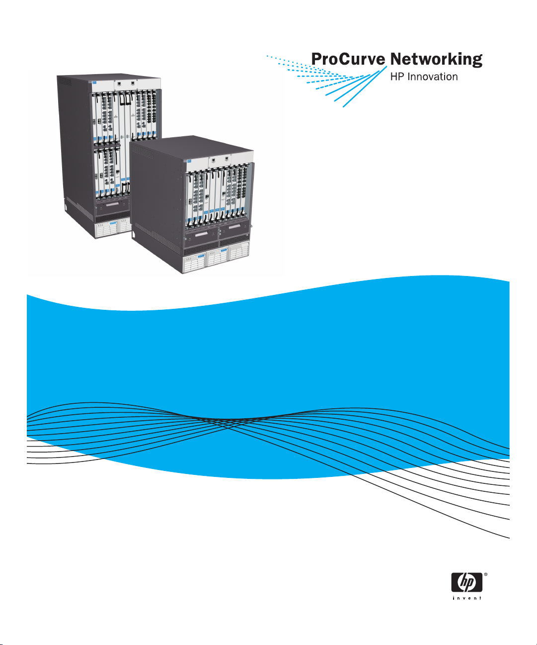
Installation and Getting
Started Guide
ProCurve Series 8100fl Switches
www.procurve.com
Page 2

Page 3

ProCurve Series 8100fl Switches
Installation and Getting Started Guide
Page 4

© Copyright 2005–2007 Hewlett-Packard Development Company,
L.P. The information contained herein is subject to change
without notice.
This document contains proprietary information, which is
protected by copyright. No part of this document may be
photocopied, reproduced, or translated into another
language without the prior written consent of
Hewlett-Packard.
Publication Number
5991-6191
February 2007
Applicable Products
ProCurve Switch 8108fl (J8727A)
ProCurve Switch 8116fl (J8728A)
Disclaimer
HEWLETT-PACKARD COMPANY MAKES NO WARRANTY
OF ANY KIND WITH REGARD TO THIS MATERIAL,
INCLUDING, BUT NOT LIMITED TO, THE IMPLIED
WARRANTIES OF MERCHANTABILITY AND FITNESS
FOR A PARTICULAR PURPOSE. Hewlett-Packard shall not
be liable for errors contained herein or for incidental or
consequential damages in connection with the furnishing,
performance, or use of this material.
The only warranties for ProCurve Networking products and
services are set forth in the express warranty statements
accompanying such products and services. Nothing herein
should be construed as constituting an additional warranty.
ProCurve Networking shall not be liable for technical or
editorial errors or omissions contained herein.
Hewlett-Packard assumes no responsibility for the use or
reliability of its software on equipment that is not furnished
by Hewlett-Packard.
Warranty
See the Customer Support/Warranty booklet included with
the product.
A copy of the specific warranty terms applicable to your
Hewlett-Packard products and replacement parts can be
obtained from your ProCurve Networking Sales and Service
Office or authorized dealer.
Hewlett-Packard Company
8000 Foothills Boulevard, m/s 5552
Roseville, California 95747-5552
www.procurve.com
Safety
Before installing and operating these products, please read
the
“Installation Guidelines” in Chapter 2 and the safety
statements in “Safety and Regulatory Statements”.
Page 5

Contents
1 Introducing the ProCurve Series 8100fl Switch
Front of the Switch . . . . . . . . . . . . . . . . . . . . . . . . . . . . . . . . . . . . . . . . . . . . . . 1-2
Switch Chassis . . . . . . . . . . . . . . . . . . . . . . . . . . . . . . . . . . . . . . . . . . . . . . 1-3
Console Ports . . . . . . . . . . . . . . . . . . . . . . . . . . . . . . . . . . . . . . . . . . . 1-3
Slot Covers . . . . . . . . . . . . . . . . . . . . . . . . . . . . . . . . . . . . . . . . . . . . . 1-3
Backplane . . . . . . . . . . . . . . . . . . . . . . . . . . . . . . . . . . . . . . . . . . . . . . 1-3
Modules . . . . . . . . . . . . . . . . . . . . . . . . . . . . . . . . . . . . . . . . . . . . . . . . . . . 1-3
Switch Fabric Module . . . . . . . . . . . . . . . . . . . . . . . . . . . . . . . . . . . . 1-4
Management Module . . . . . . . . . . . . . . . . . . . . . . . . . . . . . . . . . . . . . 1-4
Interface Modules and Accessories . . . . . . . . . . . . . . . . . . . . . . . . . 1-5
Power Supply . . . . . . . . . . . . . . . . . . . . . . . . . . . . . . . . . . . . . . . . . . . . . . . 1-5
Fan Trays . . . . . . . . . . . . . . . . . . . . . . . . . . . . . . . . . . . . . . . . . . . . . . . . . . 1-6
LEDs . . . . . . . . . . . . . . . . . . . . . . . . . . . . . . . . . . . . . . . . . . . . . . . . . . . . . . 1-6
Management Module LEDs . . . . . . . . . . . . . . . . . . . . . . . . . . . . . . . . 1-6
Switch Fabric Module LEDs . . . . . . . . . . . . . . . . . . . . . . . . . . . . . . . 1-7
Interface Module LEDs . . . . . . . . . . . . . . . . . . . . . . . . . . . . . . . . . . . 1-8
Back of the Switch: Power Connectors . . . . . . . . . . . . . . . . . . . . . . . . . . . . 1-13
ProCurve Switch 8100fl Features . . . . . . . . . . . . . . . . . . . . . . . . . . . . . . . . . 1-14
2 Installing the ProCurve Switch 8100fl
Parts and Part Numbers . . . . . . . . . . . . . . . . . . . . . . . . . . . . . . . . . . . . . . . . . . 2-1
Switch 8108fl (J8727A) . . . . . . . . . . . . . . . . . . . . . . . . . . . . . . . . . . . . . . . 2-1
Switch 8116fl (J8728A) . . . . . . . . . . . . . . . . . . . . . . . . . . . . . . . . . . . . . . . 2-2
Additional Parts . . . . . . . . . . . . . . . . . . . . . . . . . . . . . . . . . . . . . . . . . . . . . 2-3
Installation Procedures . . . . . . . . . . . . . . . . . . . . . . . . . . . . . . . . . . . . . . . . . . 2-4
Summary . . . . . . . . . . . . . . . . . . . . . . . . . . . . . . . . . . . . . . . . . . . . . . . . . . . 2-4
Installation Guidelines . . . . . . . . . . . . . . . . . . . . . . . . . . . . . . . . . . . . . . . 2-5
1. Preparing the Installation Site . . . . . . . . . . . . . . . . . . . . . . . . . . . . . . . 2-7
Cabling Infrastructure . . . . . . . . . . . . . . . . . . . . . . . . . . . . . . . . . . . . 2-7
Installation Location . . . . . . . . . . . . . . . . . . . . . . . . . . . . . . . . . . . . . 2-8
2. Mounting the Switch . . . . . . . . . . . . . . . . . . . . . . . . . . . . . . . . . . . . . . . 2-9
3. Installing Fan Trays . . . . . . . . . . . . . . . . . . . . . . . . . . . . . . . . . . . . . . . 2-15
iii
Page 6

4. Installing Modules . . . . . . . . . . . . . . . . . . . . . . . . . . . . . . . . . . . . . . . . 2-16
Hot Swapping Modules . . . . . . . . . . . . . . . . . . . . . . . . . . . . . . . . . . 2-17
Installing a Switch Fabric Module . . . . . . . . . . . . . . . . . . . . . . . . . 2-18
Installing a Management Module . . . . . . . . . . . . . . . . . . . . . . . . . . 2-20
Installing an Interface Module . . . . . . . . . . . . . . . . . . . . . . . . . . . . 2-22
5. Installing AC Power Supplies . . . . . . . . . . . . . . . . . . . . . . . . . . . . . . 2-24
6. Connecting a Console to the Switch . . . . . . . . . . . . . . . . . . . . . . . . . 2-27
Terminal Configuration . . . . . . . . . . . . . . . . . . . . . . . . . . . . . . . . . . 2-27
Direct Console Access . . . . . . . . . . . . . . . . . . . . . . . . . . . . . . . . . . . 2-28
Telnet Console Access . . . . . . . . . . . . . . . . . . . . . . . . . . . . . . . . . . 2-28
7. Verifying the Installation . . . . . . . . . . . . . . . . . . . . . . . . . . . . . . . . . . 2-29
8. Connecting Network Devices . . . . . . . . . . . . . . . . . . . . . . . . . . . . . . 2-31
Sample Network Topologies . . . . . . . . . . . . . . . . . . . . . . . . . . . . . . . . . . . . . 2-32
Connecting ProCurve Intelligent EDGE Devices . . . . . . . . . . . . . . . . 2-32
Expanding Your Network . . . . . . . . . . . . . . . . . . . . . . . . . . . . . . . . . . . . 2-33
3 Getting Started With Switch Configuration
Booting Up and Accessing the CLI . . . . . . . . . . . . . . . . . . . . . . . . . . . . . . . . . 3-1
Setting Basic System Information . . . . . . . . . . . . . . . . . . . . . . . . . . . . . . . . . 3-2
Setting the Management Module IP Address . . . . . . . . . . . . . . . . . . . . . 3-2
Saving and Using the New Configuration . . . . . . . . . . . . . . . . . . . . . . . 3-4
Setting the System Date and Time . . . . . . . . . . . . . . . . . . . . . . . . . . . . . 3-4
Setting System Parameters . . . . . . . . . . . . . . . . . . . . . . . . . . . . . . . . . . . 3-5
Setting the Host Name . . . . . . . . . . . . . . . . . . . . . . . . . . . . . . . . . . . . 3-5
Setting System ID, Location, and Contact . . . . . . . . . . . . . . . . . . . 3-5
iv
Setting Up Passwords . . . . . . . . . . . . . . . . . . . . . . . . . . . . . . . . . . . . . . . . . . . 3-6
Specifying the CLI-level Password . . . . . . . . . . . . . . . . . . . . . . . . . . . . . 3-6
Specifying Line-level Passwords . . . . . . . . . . . . . . . . . . . . . . . . . . . . . . . 3-7
Recovering from Forgotten Passwords . . . . . . . . . . . . . . . . . . . . . . . . . 3-8
Enabling Secure Shell (SSH) Access . . . . . . . . . . . . . . . . . . . . . . . . . . . 3-9
Updating Software . . . . . . . . . . . . . . . . . . . . . . . . . . . . . . . . . . . . . . . . . . . . . 3-10
Where to Go From Here . . . . . . . . . . . . . . . . . . . . . . . . . . . . . . . . . . . . . 3-11
Page 7

4 Replacing Hardware
Replacing Power Supplies . . . . . . . . . . . . . . . . . . . . . . . . . . . . . . . . . . . . . . . . 4-2
Replacing Fan Trays . . . . . . . . . . . . . . . . . . . . . . . . . . . . . . . . . . . . . . . . . . . . . 4-3
Replacing Modules . . . . . . . . . . . . . . . . . . . . . . . . . . . . . . . . . . . . . . . . . . . . . . 4-4
Hot Swapping and Redundancy . . . . . . . . . . . . . . . . . . . . . . . . . . . . . . . 4-4
Fail Over Protection . . . . . . . . . . . . . . . . . . . . . . . . . . . . . . . . . . . . . 4-5
Configuration Changes . . . . . . . . . . . . . . . . . . . . . . . . . . . . . . . . . . . 4-6
Removal and Installation Precautions . . . . . . . . . . . . . . . . . . . . . . . . . . 4-6
Removing Modules . . . . . . . . . . . . . . . . . . . . . . . . . . . . . . . . . . . . . . . . . . 4-6
Installing Modules . . . . . . . . . . . . . . . . . . . . . . . . . . . . . . . . . . . . . . . . . . . 4-7
Verifying the Installation . . . . . . . . . . . . . . . . . . . . . . . . . . . . . . . . . . . . . 4-7
Replacing Compact Flash Card . . . . . . . . . . . . . . . . . . . . . . . . . . . . . . . . . . . 4-8
Installing or Removing Transceivers and Connecting Cables . . . . . . . . . . 4-9
Installing Transceivers . . . . . . . . . . . . . . . . . . . . . . . . . . . . . . . . . . . . . . . 4-9
Removing Transceivers . . . . . . . . . . . . . . . . . . . . . . . . . . . . . . . . . . . . . 4-10
(Optional) Installing an Optical Media Converter . . . . . . . . . . . . . . . . 4-10
Connecting Network Cables to Transceiver Ports . . . . . . . . . . . . . . . 4-11
Replacing Mini-GBICs . . . . . . . . . . . . . . . . . . . . . . . . . . . . . . . . . . . . . . . . . . 4-12
Removing Mini-GBICs . . . . . . . . . . . . . . . . . . . . . . . . . . . . . . . . . . . . . . 4-12
Installing mini-GBICs . . . . . . . . . . . . . . . . . . . . . . . . . . . . . . . . . . . . . . . 4-15
5 Troubleshooting
Basic Troubleshooting Tips . . . . . . . . . . . . . . . . . . . . . . . . . . . . . . . . . . . . . . 5-1
Troubleshooting Procedures . . . . . . . . . . . . . . . . . . . . . . . . . . . . . . . . . . . . . . 5-3
Hardware Diagnostic Tests . . . . . . . . . . . . . . . . . . . . . . . . . . . . . . . . . . . . . . . 5-6
Resetting the Switch . . . . . . . . . . . . . . . . . . . . . . . . . . . . . . . . . . . . . . . . . 5-6
Testing Twisted-Pair Cabling . . . . . . . . . . . . . . . . . . . . . . . . . . . . . . . . . . 5-6
Testing Switch-to-Device Network Communications . . . . . . . . . . . . . 5-7
Testing End-to-End Network Communications . . . . . . . . . . . . . . . . . . 5-7
Restoring the Factory Default Configuration . . . . . . . . . . . . . . . . . . . . . . . . 5-8
ProCurve Networking Customer Support . . . . . . . . . . . . . . . . . . . . . . . . . . . 5-9
v
Page 8

Before Calling Support . . . . . . . . . . . . . . . . . . . . . . . . . . . . . . . . . . . . . . . 5-9
Downloading New Code . . . . . . . . . . . . . . . . . . . . . . . . . . . . . . . . . . . . . . . . 5-10
A Specifications
Switch 8108fl . . . . . . . . . . . . . . . . . . . . . . . . . . . . . . . . . . . . . . . . . . . . . . . . . . A-1
Physical . . . . . . . . . . . . . . . . . . . . . . . . . . . . . . . . . . . . . . . . . . . . . . . . . . A-1
Electrical . . . . . . . . . . . . . . . . . . . . . . . . . . . . . . . . . . . . . . . . . . . . . . . . . A-2
Environmental . . . . . . . . . . . . . . . . . . . . . . . . . . . . . . . . . . . . . . . . . . . . A-2
Acoustic . . . . . . . . . . . . . . . . . . . . . . . . . . . . . . . . . . . . . . . . . . . . . . . . . . A-2
Safety and Regulatory . . . . . . . . . . . . . . . . . . . . . . . . . . . . . . . . . . . . . . . A-2
Switch 8116fl . . . . . . . . . . . . . . . . . . . . . . . . . . . . . . . . . . . . . . . . . . . . . . . . . . A-3
Physical . . . . . . . . . . . . . . . . . . . . . . . . . . . . . . . . . . . . . . . . . . . . . . . . . . A-3
Electrical . . . . . . . . . . . . . . . . . . . . . . . . . . . . . . . . . . . . . . . . . . . . . . . . . A-4
Environmental . . . . . . . . . . . . . . . . . . . . . . . . . . . . . . . . . . . . . . . . . . . . A-4
Acoustic . . . . . . . . . . . . . . . . . . . . . . . . . . . . . . . . . . . . . . . . . . . . . . . . . . A-4
Safety and Regulatory . . . . . . . . . . . . . . . . . . . . . . . . . . . . . . . . . . . . . . . A-4
B Switch Ports and Network Cables
Switch Ports and Connectors . . . . . . . . . . . . . . . . . . . . . . . . . . . . . . . . B-1
Twisted Pairs . . . . . . . . . . . . . . . . . . . . . . . . . . . . . . . . . . . . . . . . . . B-1
Fiber-Optic . . . . . . . . . . . . . . . . . . . . . . . . . . . . . . . . . . . . . . . . . . . . B-1
Cables . . . . . . . . . . . . . . . . . . . . . . . . . . . . . . . . . . . . . . . . . . . . . . . . . . . . B-2
Twisted-Pair Cables . . . . . . . . . . . . . . . . . . . . . . . . . . . . . . . . . . . . . B-2
Fiber-Optic Cables . . . . . . . . . . . . . . . . . . . . . . . . . . . . . . . . . . . . . . B-3
CX4 Copper Cables . . . . . . . . . . . . . . . . . . . . . . . . . . . . . . . . . . . . . B-4
vi
Twisted-Pair Cable/Connector Pin-Outs . . . . . . . . . . . . . . . . . . . . . . . . . . . B-5
Straight-Through Twisted-Pair Cable for
10/100 Mbps Network Connections . . . . . . . . . . . . . . . . . . . . . . . . . . . B-6
Cable Diagram . . . . . . . . . . . . . . . . . . . . . . . . . . . . . . . . . . . . . . . . . B-6
Pin Assignments . . . . . . . . . . . . . . . . . . . . . . . . . . . . . . . . . . . . . . . B-6
Page 9

Straight-Through Twisted-Pair Cable for
1000 Mbps Network Connections . . . . . . . . . . . . . . . . . . . . . . . . . . . . . B-7
Cable Diagram . . . . . . . . . . . . . . . . . . . . . . . . . . . . . . . . . . . . . . . . . B-7
Pin Assignments . . . . . . . . . . . . . . . . . . . . . . . . . . . . . . . . . . . . . . . . B-7
Serial Port Cable and Connections . . . . . . . . . . . . . . . . . . . . . . . . . . . . . . . B-8
RJ-45 to DB-9 Adapter Pin-outs . . . . . . . . . . . . . . . . . . . . . . . . . . . . . . . B-8
C Safety and Regulatory Statements
Safety Information . . . . . . . . . . . . . . . . . . . . . . . . . . . . . . . . . . . . . . . . . . . . . C-1
Informations concernant la sécurité . . . . . . . . . . . . . . . . . . . . . . . . . . . . . . C-2
Hinweise zur Sicherheit . . . . . . . . . . . . . . . . . . . . . . . . . . . . . . . . . . . . . . . . . C-3
Considerazioni sulla sicurezza . . . . . . . . . . . . . . . . . . . . . . . . . . . . . . . . . . . C-4
Consideraciones sobre seguridad . . . . . . . . . . . . . . . . . . . . . . . . . . . . . . . . C-5
Safety Information (Japan) . . . . . . . . . . . . . . . . . . . . . . . . . . . . . . . . . . . . . . C-6
Safety Information (China) . . . . . . . . . . . . . . . . . . . . . . . . . . . . . . . . . . . . . . C-7
EMC Regulatory Statements . . . . . . . . . . . . . . . . . . . . . . . . . . . . . . . . . . . . . C-8
U.S.A. . . . . . . . . . . . . . . . . . . . . . . . . . . . . . . . . . . . . . . . . . . . . . . . . . . . . C-8
Canada . . . . . . . . . . . . . . . . . . . . . . . . . . . . . . . . . . . . . . . . . . . . . . . . . . . C-8
Australia/New Zealand . . . . . . . . . . . . . . . . . . . . . . . . . . . . . . . . . . . . . . C-8
Japan . . . . . . . . . . . . . . . . . . . . . . . . . . . . . . . . . . . . . . . . . . . . . . . . . . . . . C-8
Korea . . . . . . . . . . . . . . . . . . . . . . . . . . . . . . . . . . . . . . . . . . . . . . . . . . . . . C-9
Taiwan . . . . . . . . . . . . . . . . . . . . . . . . . . . . . . . . . . . . . . . . . . . . . . . . . . . C-9
Regulatory Model Identification Number . . . . . . . . . . . . . . . . . . . . . . C-9
Regulatory Information (China) . . . . . . . . . . . . . . . . . . . . . . . . . . . . . . . . . C-11
D Waste Electrical and Electronic Equipment (WEEE)
Statements
Index
vii
Page 10

— This page is intentionally unused. —
Page 11
Introducing the ProCurve Series 8100fl Switch
The ProCurve Series 8100fl switches are multiport modular switches that
perform non-blocking, wire-speed, layer-2 switching, layer-3 routing, and
layer-4 application switching. They are designed to interconnect LAN
networks built upon the ProCurve Adaptive EDGE Architecture, as an
alternative to traditional core routing switches. These interconnect switches
provide high bandwidth, high availability, and high performance connectivity
between Intelligent EDGE devices, supporting applications that require
security and convergence decisions at the edge of your network.
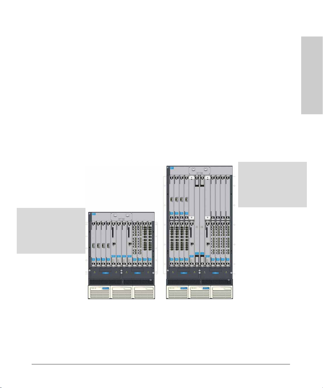
The ProCurve Series 8100fl switches include the Switch 8108fl and the Switch
8116fl. This chapter describes both switches including:
■ Front and back of a switch
■ Hardware and software features (see page 1-14 for details)
Switch 8116fl
16 Interface Module slots
– Up to 160 100/1000-T ports
– Up to 160 Gigabit fiber ports
– Up to 32 10 Gigabit flexible media
Switch 8108fl
8 Interface Module slots
– Up to 80 100/1000-T ports
– Up to 80 Gigabit fiber ports
– Up to 16 10 Gigabit flexible media
transceiver ports
1
Introducing the ProCurve
Series 8100fl Switch
transceiver ports
ProCurve Switch 8108fl
(J8727A)
ProCurve Switch 8116fl
(J8728A)
Switch 8108fl and Switch 8116fl. The Switch 8108fl is an 8-slot chassis
that comes with one management module, one switch fabric module, one
backplane, and one power supply. The Switch 8116fl is a 16-slot chassis with
one management module, one switch fabric module, one backplane, and two
power supplies. Both switches support the same interface modules.
1-1
Page 12
Introducing the ProCurve Series 8100fl Switch
Front of the Switch
Series 8100fl Switch
Introducing the ProCurve
Front of the Switch
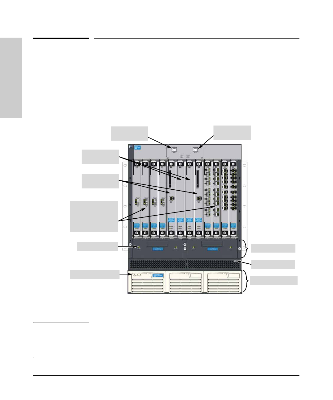
This section describes the following ProCurve Switch 8100fl components:
■ Switch Chassis
■ Modules
■ Power System
■ Fan Assembly
■ LEDs
Switch Fabric
Modules
Management
Modules
Interface Modules
(Slots 1-4 and 5-8
in the Switch 8108fl;
Slots 1-8 and 9-16
in the Switch 8116fl)
Fan Status LED
Power Status LEDs
This illustration shows a Switch 8108fl, but the labeling and descriptions also
apply to the taller Switch 8116fl.
Console Port A
RJ-45 (RS-232)
Console Port B
RJ-45 (RS-232)
Fan Trays
Grounding Port
AC Power Supplies
Note In a Switch 8116fl, the switch fabric module is sized differently. Otherwise, all
hardware components are identical. For a full listing of the physical and
environmental specifications for each model, refer to
“Specifications”.
1-2
Appendix A,
Page 13

Introducing the ProCurve Series 8100fl Switch
Front of the Switch
Switch Chassis
The Switch 8108fl is an 8-slot chassis; the Switch 8118fl is a 16-slot chassis.
Console Ports
The top of the chassis contains two RJ-45 serial console ports—one for
Management Module A (primary management module), and one for
Management Module B (secondary management module). These ports are
used to directly connect a management console to the switch by using the
RJ-45 to DB-9 adapter and straight-through cable supplied with the switch.
You can use the console port only for out-of-band management. It cannot be
used for a Telnet connection. For network connections, use the 10/100 Base-T
port on the Management module, as shown in
Slot Covers
All ProCurve Switch 8100fl slots must have an installed module or be covered
by a slot cover any time the switch is powered on. Slot covers are included in
your shipment as needed, and are half-height size, except for the full-height
slot cover for the 8116fl switch fabric module. Half-height slot covers have
different widths—switch fabric modules are wider than interface modules.
Caution Failure to cover empty slots while the system is running degrades the forced
air cooling system and can cause the system to overheat.
Table 1-1 on page 1-6.
Introducing the ProCurve
Series 8100fl Switch
Backplane
The backplane is installed at the factory and occupies the rear of the chassis.
It is designed to be completely passive to ensure high availability of the system.
The power supplies use the backplane to supply power to the system. Interface
modules and the primary management module use the backplane to exchange
control information and packets.
Modules
Each module is shipped separately from the chassis. The different types of
supported modules are described in the following sections. As of this printing,
the following modules are supported in ProCurve 8100fl switches:
■ ProCurve 8108fl Redundant Switch Fabric Module (J8729A)
■ ProCurve 8116fl Redundant Switch Fabric Module (J8730A)
■ ProCurve Switch fl Redundant Management Module (J8731A)
■ ProCurve Switch fl 1-Port 10-GbE LR Interface Module (J8733A)
1-3
Page 14

Introducing the ProCurve Series 8100fl Switch
Front of the Switch
Series 8100fl Switch
Introducing the ProCurve
Caution To avoid damaging modules and the backplane, be sure that you insert each
■ ProCurve Switch fl 10-Port 100/1000-T Interface Module (J8734A)
■ ProCurve Switch fl 10-Port Mini-GBIC Interface Module (J8735A)
■ ProCurve Switch fl 1-Port X2 10GbE Interface Module (J8736A)
■ ProCurve Switch fl 2-Port X2 10GbE Interface Module (J8737A)
The Switch 8116fl has two unused slots labelled EM above each management
module slot. These two slots are reserved for future use.
type of module into its appropriate slot.
Switch Fabric Module
Each ProCurve Switch 8100fl requires one switch fabric module to process
traffic for any interface module. A second switch fabric module can be
installed for redundancy.
Switch fabric modules (half-height module for Switch 8108fl; full-height
module for Switch 8116fl) are installed in slots labelled FM. When installing
two modules, install the primary module in slot FM-A; install the secondary
module in slot FM-B. (When installing a single switch fabric module, you can
install the module in either slot.)
Note The 8108fl switch fabric module and 8116fl switch fabric module are not
interchangeable. You can install the half-height module only in the 8108fl
Switch—the 8116fl Switch requires a full-height switch fabric module.
Management Module
A ProCurve Switch 8100fl requires at least one primary management module
to operate. You can install a second management module for redundancy.
Management modules (thicker, half-height modules) are installed in slots
labelled MM. You must install the primary management module in slot MM-A;
you can install a second redundant management module in slot MM-B.
The management module maintains persistent images of all software that runs
on the system. The primary non-volatile storage medium is a Compact Flash
card located on the module—this is a separate memory module for storing
run-time images and tables. The management module is the main processing
unit of the ProCurve Switch 8100fl chassis. It contains system-wide bridging
and routing tables, and runs the main control protocols. Traffic that does not
yet have an entry in the L2 lookup tables on individual interface modules is
sent to the management module to be learned. After processing traffic, the
1-4
Page 15

Introducing the ProCurve Series 8100fl Switch
Front of the Switch
management module updates the L2 tables on the interface modules that
received the traffic thus ensuring system-wide coordination and visibility. In
this way, the interface modules learn how to forward traffic.
Interface Modules and Accessories
Interface modules (narrow, half-height modules) provide network
connectivity options in addition to bridging and routing functionality. The
Switch 8108fl has 8 slots (numbered 1-8) for interface modules; the Switch
8116fl has 16 slots (numbered 1-16) for interface modules. The following
interface modules are supported in ProCurve 8100fl switches:
■ ProCurve Switch fl 1-Port 10-GbE LR Interface Module (J8733A)*
■ ProCurve Switch fl 10-Port 100/1000-T Interface Module (J8734A)
■ ProCurve Switch fl 10-Port Mini-GBIC Interface Module (J8735A) that
uses and supports the following mini-GBICs:
• ProCurve Gigabit-SX LC mini-GBIC (J4858B)
• ProCurve Gigabit-LX LC mini-GBIC (J4859B)
• ProCurve Gigabit-LH LC mini-GBIC (J4860B)
• ProCurve Gigabit 1000Base-T mini-GBIC (J8177B)
■ ProCurve Switch fl 1-Port X2 10GbE Module (J8736A)**
■ ProCurve Switch fl 2-Port X2 10GbE Module (J8737A) that uses and
supports the following transceivers (as of this printing):
• 10 Gigabit-X2-SC SR Optic transceiver (J8436A)
• 10 Gigabit-X2-SC LR Optic transceiver (J8437A)
• 10 Gigabit-X2-SC ER Optic transceiver (J8438A)
• 10 Gigabit-X2-CX4 copper transceiver (J8440A)
– 10 Gigabit-X2-CX4 Optical Media Converter (J8439A)
* Discontinued in Summer 2006.
** Discontinued in Spring 2007. Replaced by the 2-Port X2 10Gbe Module
(J8737A).
Introducing the ProCurve
Series 8100fl Switch
Power Supply
The ProCurve Switch fl Redundant Power Supply (J8732A) operates between
100–240 VAC. Each component (management module, interface module, and
so on) regulates its own power needs. The Switch 8108fl requires one power
supply to operate a fully-populated chassis—an optional second power
supply provides for redundancy. For the Switch 8116fl, two power supplies
are required to operate a fully-populated chassis—an optional third power
supply provides for redundancy.
1-5
Page 16
Introducing the ProCurve Series 8100fl Switch
Front of the Switch
Fan Trays
The chassis contains two fan tray assemblies to provide a cooling air flow
across the switch modules. Each fan tray assembly contains three fans. The
fan tray assembly is hot swappable to allow for easy replacement of fans.
LEDs
Series 8100fl Switch
Introducing the ProCurve
Management Module LED Color State Meaning
The tables in this section describe how the LEDs on the switch chassis and
modules show the operational status of the switch and network connections.
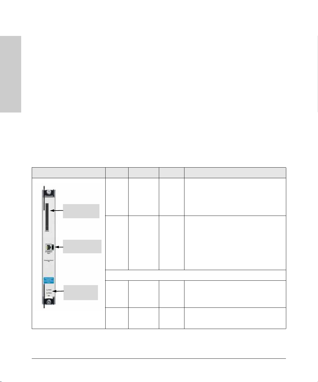
Management Module LEDs
The management module has Active and Status LEDs showing the module’s
operational status, plus LEDs on the RJ-45 port showing network connections.
The LED states are described in the following table.
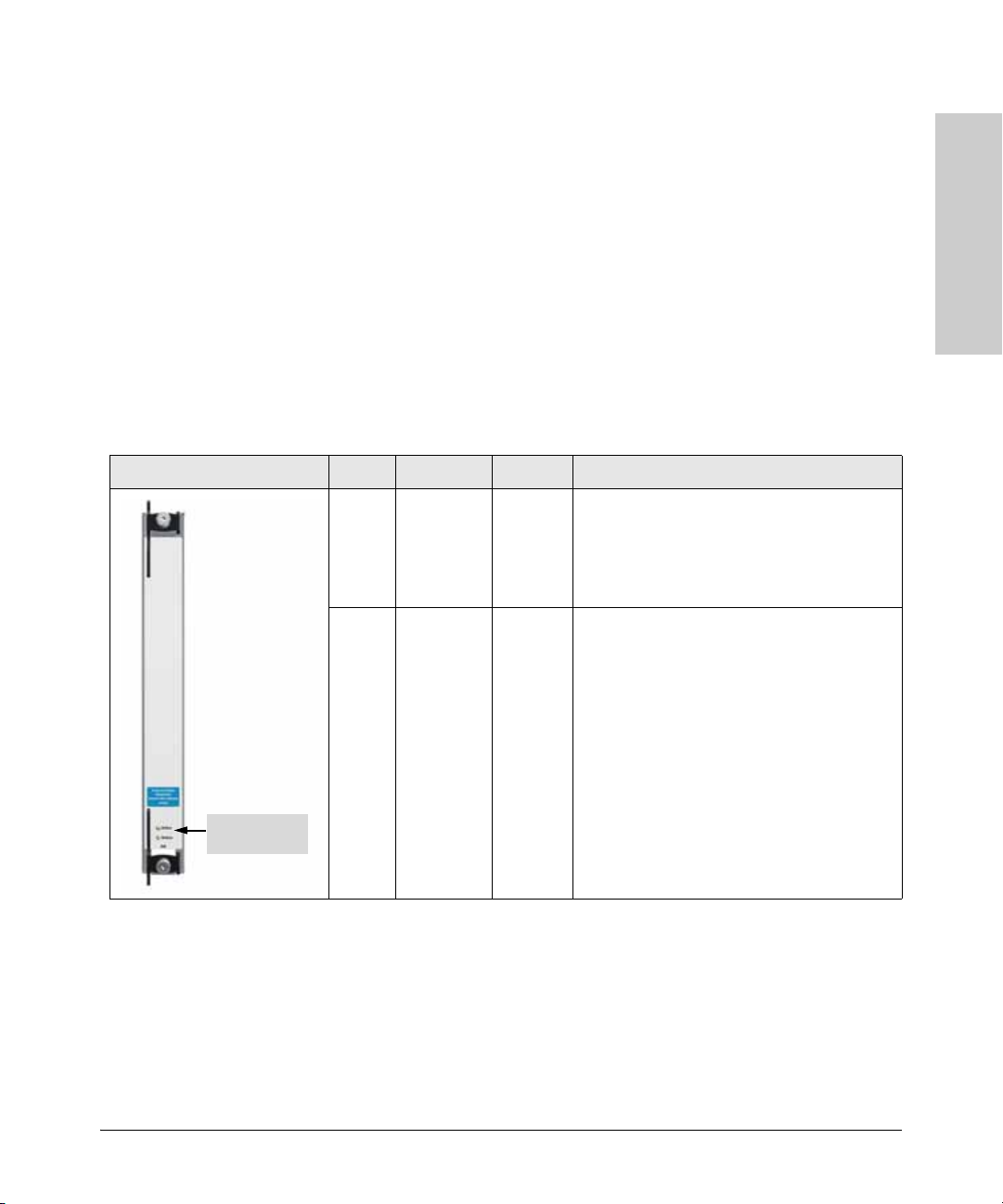
Table 1-1. Management Module (J8731A) LEDs
PCMCIA Card
Slot
10/100 Base-T
Port (RJ-45)
Active Green
Green
n/a
Status n/a
Green
Green
Yellow/
Orange
Flashing
Solid
Off
Off
Flashing
Solid
Flashing
Negotiating active/backup management
module(s) during boot sequence.
Module is active - normal.
Module is in back up mode.
No power to the module.
Module is booting up and downloading
operating software.
Module is in service - normal.
Self-test failure.
1-6
Active and
Status LEDs
10/100 Base-T Port
Activity
(Act)
Link n/a
n/a
Green
Green
Off
Flashing
Off
Solid
No data is being transferred and/or no
connector is plugged into the port.
Transmitting data.
No connector is plugged into the port.
Link is up.
Page 17
Introducing the ProCurve Series 8100fl Switch
Front of the Switch
10/100 Base-T Data Terminal Equipment (DTE) Port. Use the
RJ-45 port to manage a ProCurve 8100fl Switch from a management
workstation through an inband Telnet session. The RJ-45 port is configured
as a media data interface (MDI). For out-of-band console access, you can also
connect directly to the RJ-45 serial port on top of the chassis (see
PCMCIA Flash Card. The PCMCIA card slot holds a PC flash memory card
(reserved for future software releases).
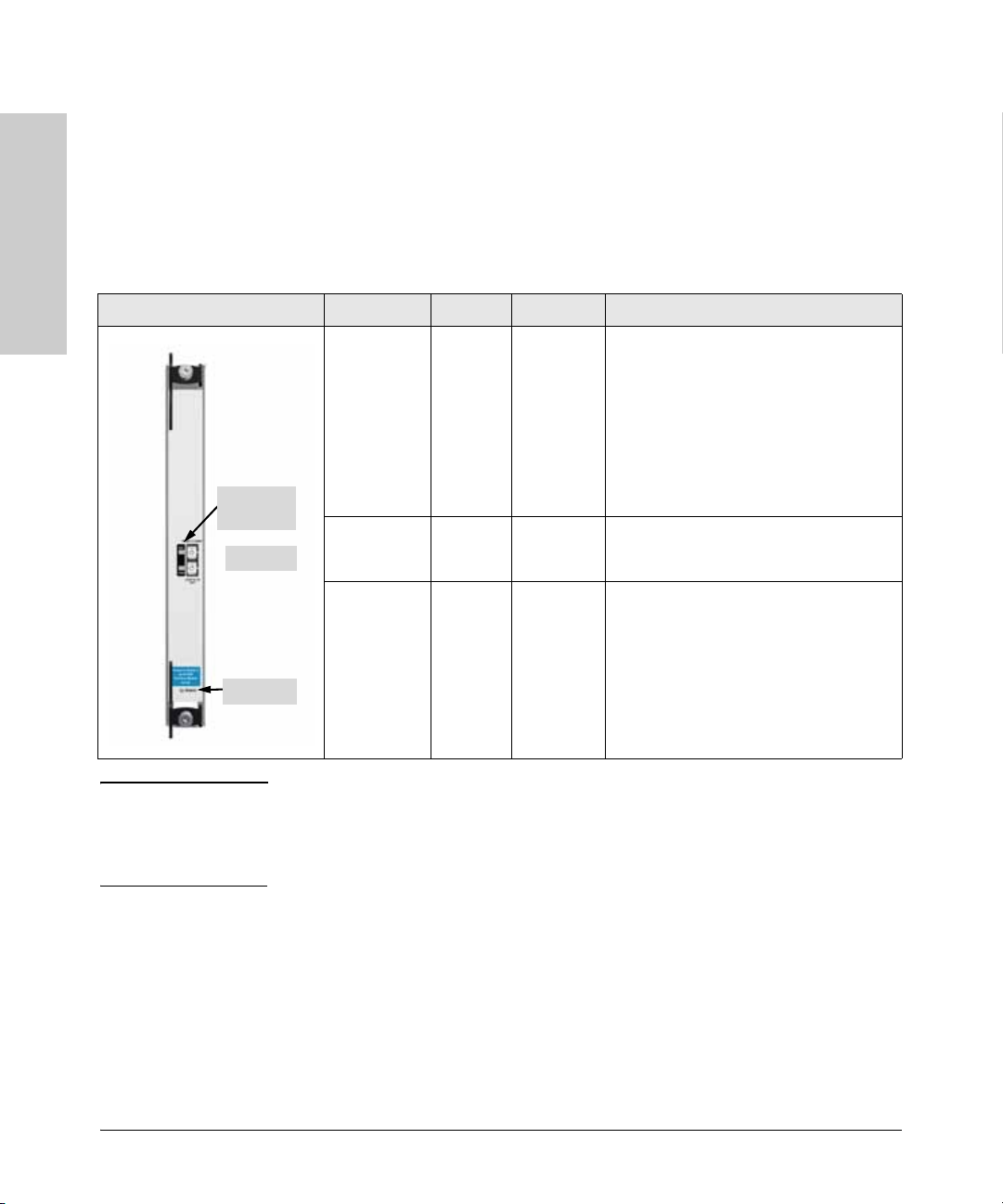
Switch Fabric Module LEDs
Switch fabric modules have two LEDs: an Active LED (on top) and a Status
LED (on bottom). The LED states are described in the following table.
Table 1-2. Switch Fabric Module (J8729A/J8730A) LED
Switch Fabric Module LEDs LED Color State Meaning
Active Green
Green
n/a
Status n/a
Green
Flashing
Solid
Off
Off
Flashing
Negotiating active/backup switch fabric
module(s) during boot sequence.
Module is active - normal.
Module is in back up mode.
No power to the module.
Module is powering up and downloading
operating software.
Introducing the ProCurve
Series 8100fl Switch
page 2-27).
Active and
Status LEDs
Green
Yellow/
Orange
Solid
Flashing
Module is in service - normal.
Self-test failure.
1-7
Page 18
Introducing the ProCurve Series 8100fl Switch
Front of the Switch
Interface Module LEDs
Interface modules have LEDs showing activity and link status by port, plus a
Status LED at the bottom showing the operational status of each module. LED
function and behavior differs according to module (refer to the following
tables for details).
Table 1-3. 1-Port 10GB LR Module (J8733A) LEDs
Series 8100fl Switch
Introducing the ProCurve
1-Port 10GB LR Module LED Color State Meaning
Note This module was discontinued in Summer 2006. The 2-Port X2 10Gbe Module
Activity and
Link LEDs
LR port
Status LED
Activity
(Act)
Link Green
Status n/a
(J8737A) shown on
Green
Green
Off
n/a
Green
Green
Yellow/
Orange
Flashing
Solid
Flashing
Solid
Off
Off
Flashing
Solid
Flashing
Transmitting data.
Link is up; no data is being transferred.
When no connector is plugged into the
port, the LED will flash approximately
once every few seconds. This on/off cycle
is a safety feature known as Auto Laser
Shutdown.
Link is up.
No connector is plugged into the port.
No power to the module.
Module is powering up and downloading
operating software.
Software image loaded successfully.
Self-test failure.
page 1-12, provides functionally-equivalent LR
connectivity (with separate purchase of LR transceivers) in a two port X2,
media-flexible package.
1-8
Page 19
Introducing the ProCurve Series 8100fl Switch
Front of the Switch
10-Port 100/1000Base-T
Module
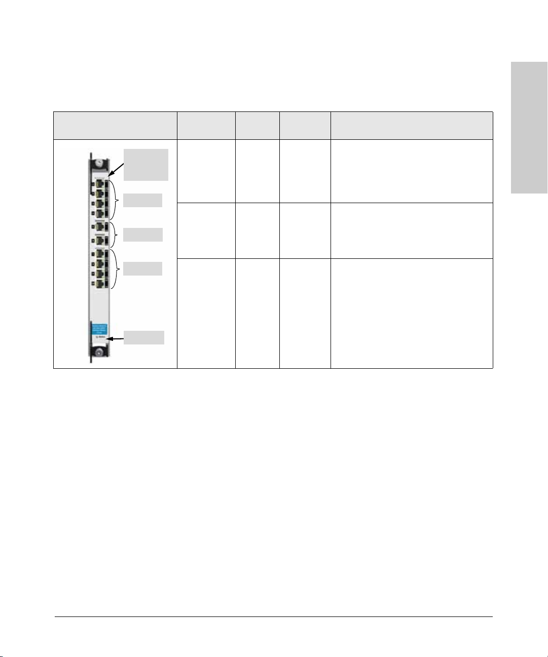
Link and
Activity LEDs
(per port)
Ports 1-4
Ports 5-6
Ports 7-10
Status LED
Table 1-4. 10-Port 100/1000Base-T Module (J8734A) LEDs
The 10-Port 100/1000 Base-T Module shows the link status of each port on top
and has an LED showing the activity status of each port on the bottom.
LED Color State Meaning
Link
(per port)
Activity
(per port)
Status n/a
Green
Amber
n/a
Green
n/a
Green
Green
Yellow/
Orange
Solid
Solid
Off
Flashing
Off
Off
Flashing
Solid
Flashing
Port is in 1000 Mbps mode.
Port is in 100 Mbps mode.
No connector is plugged into the port.
Transmitting data.
No data is being transferred, and/or no
connector is plugged into the port.
No power to the module.
Module is powering up and downloading
operating software.
Software image loaded successfully.
Self-test failure.
Introducing the ProCurve
Series 8100fl Switch
1-9
Page 20
Introducing the ProCurve Series 8100fl Switch
Front of the Switch
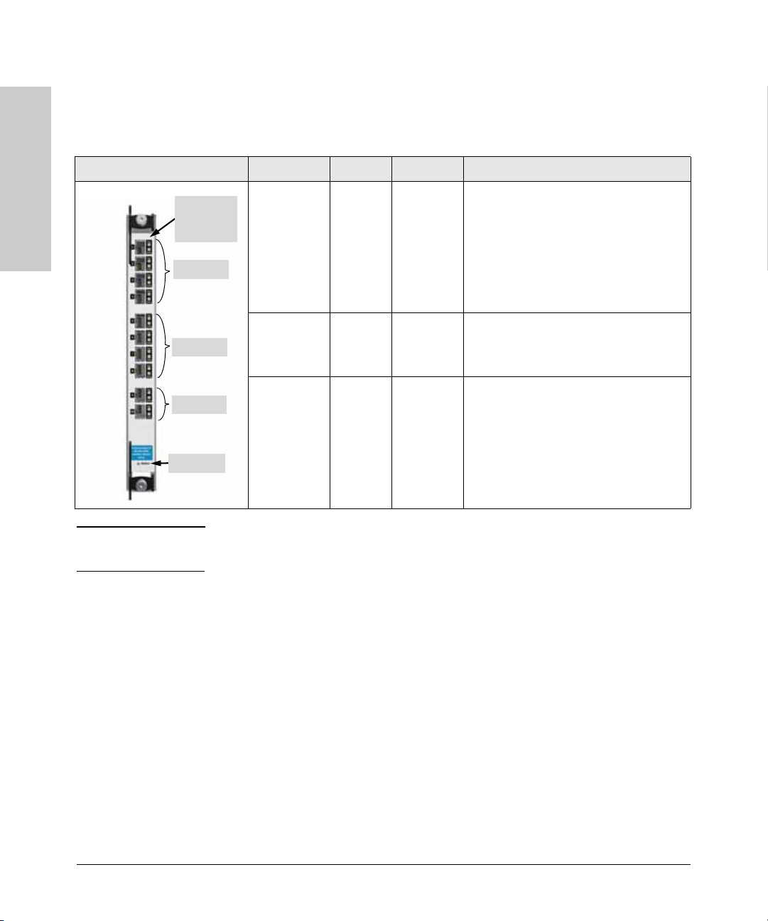
Table 1-5. 10-Port mini-GBIC Module (J8735A) LEDs
The 10-Port mini-GBIC Module shows the activity status of each port on top
and has an LED showing the link status of each port on the bottom.
10-Port mini-GBIC Module LED Color State Meaning
Series 8100fl Switch
Introducing the ProCurve
Note The 10-Port mini-GBIC Module supports various ProCurve mini-GBICs. Refer
Activity and
Link LEDs
(per port)
Ports 1-4
Ports 5-8
Ports 9-10
Status LED
Activity
(per port)
Link
(per port)
Status n/a
Green
Green
Off
Green
n/a
Green
Green
Yellow/
Orange
Flashing
Solid
Flashing
Solid
Off
Off
Flashing
Solid
Flashing
Transmitting data.
Link is up; no data is being transferred.
When no connector is plugged into the
port, the LED will flash approximately
once every four seconds. This is a safety
feature known as Auto Laser Shutdown
Link is up.
No connector is plugged into the port.
No power to the module.
Module is powering up and downloading
operating software.
Software image loaded successfully.
Self-test failure.
to the ProCurve Switch fl Modules Installation Guide for further details.
1-10
Page 21
Introducing the ProCurve Series 8100fl Switch
Front of the Switch
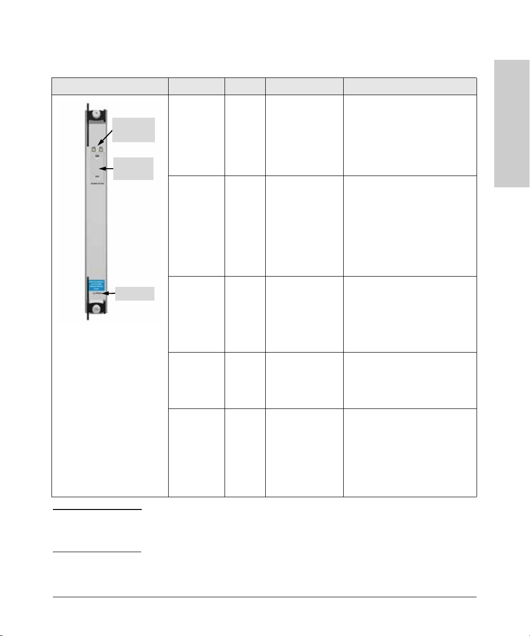
Table 1-6. 1-Port X2 10GbE Module (J8736A) LEDs
1-Port X2 10GbE Module LED Color State Meaning
Link and
Activity LEDs
Transceiver
slot cover
Status LED
Link Green
Orange
n/a
Activity
(Act)
Link and
Activity
(both port
LEDs
together)
Green
Green
n/a
Orange/
Green/
Off
Solid
Flashing
Off
Flashing
Solid
Off
Solid Orange (0.5
secs), then Solid
Green (1.5 secs),
and then Off
Link is up
Self-test failure or unsupported
transceiver. See Error Log for
details.
No connector is plugged into the
port.
Transmitting data. Blink rate
indicates traffic utilization of the
port.
Traffic exceeds 90% of link
capacity.
No connector is plugged into the
port, or no traffic is being passed
through the port.
A transceiver has been correctly
inserted into the transceiver port.
After the insertion test, the LEDs
will remain Off until a network
cable is inserted into the
transceiver and the LEDs follow
their normal operational behavior.
Introducing the ProCurve
Series 8100fl Switch
Link, Activity
and Status
(all module
LEDs
together)
Status n/a
Orange/
Green/
Off
Green
Green
Amber
Solid Orange (0.5
secs), then Solid
Green (1.5 secs),
and then Off
Off
Flashing
Solid
Flashing
The module is receiving initial
power due to being inserted into
the slot, and/or due to the slot being
enabled via the CLI.
No power to the module.
Module is powering up and
downloading operating software.
Software image loaded
successfully.
Self-test failure.
Note This module’s discontinuance is in Spring 2007. The 2-Port X2 10Gbe Module
(J8737A) shown on
media-flexible connectivity in a two port package.
page 1-12, provides functionally-equivalent X2
1-11
Page 22

Introducing the ProCurve Series 8100fl Switch
Front of the Switch
Table 1-7. 2-Port X2 10GbE Module (J8737A) LEDs
2-Port X2 10GbE Module LED Color State Meaning
Series 8100fl Switch
Introducing the ProCurve
Port 1
Port 2
Link and
Activity LEDs
Transceiver
slot cover
Status LED
Link Green
Orange
n/a
Activity
(Act)
Link and
Activity
(both port
LEDs
together)
Link, Activity
and Status
(all module
LEDs
together)
Green
Green
n/a
Orange/
Green/
Off
Orange/
Green/
Off
Solid
Flashing
Off
Flashing
Solid
Off
Solid Orange (0.5
secs), then Solid
Green (1.5 secs),
and then Off
Solid Orange (0.5
secs), then Solid
Green (1.5 secs),
and then Off
Link is up
Self-test failure or unsupported
transceiver. See Error Log for
details.
No connector is plugged into the
port.
Transmitting data. Blink rate
indicates traffic utilization of the
port.
Traffic exceeds 90% of link
capacity.
No connector is plugged into the
port, or no traffic is being passed
through the port.
A transceiver has been correctly
inserted into the transceiver port.
After the insertion test, the LEDs
will remain Off until a network
cable is inserted into the
transceiver and the LEDs follow
their normal operational behavior.
The module is receiving initial
power due to being inserted into
the slot, and/or due to the slot being
enabled via the CLI.
Status n/a
Green
Green
Amber
Off
Flashing
Solid
Flashing
No power to the module.
Module is powering up and
downloading operating software.
Software image loaded
successfully.
Self-test failure.
Note The 2-Port X2 10GbE Module provides two flexible media transceiver slots
that support a number of different transceivers. Refer to the ProCurve Switch
fl Modules Installation Guide for further details.
1-12
Page 23
Introducing the ProCurve Series 8100fl Switch
Back of the Switch: Power Connectors
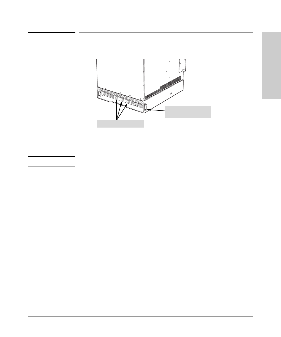
Back of the Switch: Power Connectors
Strain relief opening for
power cord
AC power receptacles
ProCurve 8100fl switches have power connections on the back at the bottom
of the chassis. Use the strain-relief opening to tie wrap the power cable.
Note If necessary, attach the power cables before installing the chassis in the rack.
Introducing the ProCurve
Series 8100fl Switch
1-13
Page 24

Introducing the ProCurve Series 8100fl Switch
ProCurve Switch 8100fl Features
ProCurve Switch 8100fl Features
The Series 8100fl Switch hardware provides wire-speed performance
regardless of the performance monitoring, filtering, and Quality of Service
(QoS) features enabled by the software.
Series 8100fl Switch
Introducing the ProCurve
ProCurve 8100fl switches support the following features:
■ Hot swapping on:
• Interface modules that can be installed in any order and combination
• Management module (when a redundant management module is
online)
• Switch fabric modules (when a redundant fabric module is online)
• Power supply (when a redundant supply is online)
• Supported mini-GBICs and transceivers
■ High performance:
• Switch 8108fl—160 Gbps aggregate switching capacity in each switch
fabric module; 80Gbps system throughput
• Switch 8116fl—320Gbps aggregate switching capacity in each switch
fabric module; 160Gbps system throughput
• Up to 238 million packets-per-second non-blocking routing
throughput
■ Full-duplex operation on all ports
■ Easy management of the switch through the following interfaces:
• Simple Network Management Protocol (SNMP) v1/v2
• Full-featured command line interface (CLI)
■ Hardware redundancy (see “Hot Swapping and Redundancy” on page 4-4
for details):
• (Optional) redundant power supply
• (Optional) redundant management module
• (Optional) redundant switch fabric module
■ Automatic routing switch failover provides hot standby redundancy using
standards-based VRRP (Virtual Router Redundancy Protocol)
■ Switch management login security:
• Terminal Access Controller Access Control System (TACACS+)
• Remote Authentication Dial In User Service (RADIUS)
• Secure Session Shells (SSH) version 1.5 and 2.0
1-14
Page 25

Introducing the ProCurve Series 8100fl Switch
ProCurve Switch 8100fl Features
■ QoS mechanisms:
• Weighted random early detection (WRED)
• Traffic prioritization based on 802.1p and Diffserv (TOS)
• Virtual Output Queuing (VOQ) architecture eliminates head of line
blocking issues within the queuing system
• Class of Service (CoS) sets 802.1p priority tag based on source port
Diffserv or 802.1p
• Guaranteed minimum bandwidths per port/per queue allows traffic
to receive guaranteed minimum bandwidth during times of
congestion
■ Port mirroring to monitor traffic from specific ports
■ Port trunking for higher switch-to-switch throughput and link-level
redundancy, with support for standards-based link aggregation (802.3ad)
■ 802.1s Multi Instance Spanning Tree Protocol to eliminate network loops
■ 802.1Q-compliant VLANs to divide the attached end nodes into logical
groupings to suit your business needs
■ Layer 3 routing functionality:
• IP static routes
• Routing Internet Protocol (RIP) V1 and V2
• Open Shortest Path First (OSPF)
• Support for equal cost multipath (ECMP)
■ Other advanced features to enhance network performance, security, and
control. For more information, refer to the Management and
Configuration Guide on the documentation CD-ROM shipped with your
switch.
Introducing the ProCurve
Series 8100fl Switch
1-15
Page 26

— This page is intentionally unused. —
Page 27

Installing the ProCurve Switch 8100fl
This chapter describes how to install a ProCurve Switch 8100fl. The
illustrations in this chapter show the 8-slot Switch 8108fl—unless otherwise
indicated, the same procedures apply to both the Switch 8108fl and the 16-slot
Switch 8116fl.
2
WARNING To avoid possible personal injury, be careful when lifting the chassis out of
the shipping box. The Switch 8108fl chassis weighs approximately 130lbs as
shipped and 94 lbs when empty; the Switch 8116fl chassis weighs over 200lbs
as shipped and 137 lbs when empty. See
for additional safety considerations when handling this product.
“Installation Guidelines” on page 2-5
Parts and Part Numbers
Note The following components are the same in both the Switch 8108fl and the
Switch 8116fl:
■ Power supplies
■ Fan trays
■ Management module
■ Interface modules
The switch fabric modules, however, are different in each model.
Switch 8108fl (J8727A)
The ProCurve Switch 8108fl is shipped in several containers with the following
components:
■ 8-slot chassis (J8727A) with blank slot covers for vacant slots (see page
2-29 for slot cover part numbers) and blank power supplies (1530-2431)
■ One ProCurve Switch fl Redundant Management Module (J8731A)
■ One ProCurve Switch 8108fl Redundant Switch Fabric Module (J8729A)
■ One ProCurve Switch fl Redundant Power Supply (J8732A)
Installing the ProCurve
Switch 8100fl
2-1
Page 28

Switch 8100fl
Installing the ProCurve
Installing the ProCurve Switch 8100fl
Parts and Part Numbers
■ Two fan trays (J8989-61001)
■ Accessory kit (5069-8546):
• Rack Mount Kit (5070-0113):
– Rack mounting brackets: Right and Left
– Set of screws to attach brackets to the switch
• RJ-45 to DB-9 adapter and straight-through cable (5092-1718)
• ProCurve Switch 8100fl documentation kit:
– ReadMe First
– ProCurve Switch 8100fl Installation and Getting Started Guide,
this manual
– ProCurve Switch 8100fl Documentation CD ROM
(contains PDF file copies of the documentation for the ProCurve
8100fl switches)
– Customer Support/Warranty booklet
■ Power cable—three of the following:
Australia/New Zealand 8120-6900 Switzerland 8121-6897
China 8121-0070 Taiwan 8121-0968
Continental Europe 8120-6352 Thailand 8121-0675
Denmark 8120-6897 United Kingdom/Hong Kong/Singapore 8121-0907
Israel 8121-1010 United States/Canada/Mexico (110V) 8120-6894
Japan 8121-0942 United States/Canada/Mexico (220V) 8120-8651
South Africa 8121-0915
Japan Power
Cord W a rning
2-2
Please use the attached power cable. The attached power cable is not to
be used with any other products.
Switch 8116fl (J8728A)
The ProCurve Switch 8116fl is shipped with the following components:
■ 16-slot chassis (J8728A) with blank slot covers (see page 2-29 for slot
cover part numbers) and blank power supplies (1530-2431)
■ One ProCurve Switch fl Redundant Management Module (J8731A)
■ One ProCurve Switch 8116fl Redundant Switch Fabric Module (J8730A)
■ One ProCurve Switch fl Redundant Power Supply (J8732A)
■ Two fan trays (J8989-61001)
■ Accessory kit (5069-8547):
• Rack Mount Kit (5070-0114):
– Mounting brackets: Right and Left
Page 29

Installing the ProCurve Switch 8100fl
Parts and Part Numbers
– Set of screws to attach brackets to the switch
• RJ-45 to DB-9 adapter and straight-through cable (5092-1718)
• ProCurve Switch 8100fl documentation kit:
– ReadMe First
– ProCurve Series 8100fl Switches Installation and Getting
Started Guide, this manual
– ProCurve Switch 8100fl Documentation CD ROM
(contains PDF file copies of the documentation for the ProCurve
8100fl switches)
– Customer Support/Warranty booklet
■ Power cables, three of the following:
Japan Power
Cord W a rning
Australia/New Zealand 8120-6900 Switzerland 8121-6897
China 8121-0070 Taiwan 8121-0968
Continental Europe 8120-6352 Thailand 8121-0675
Denmark 8120-6897 United Kingdom/Hong Kong/Singapore 8121-0907
Israel 8121-1010 United States/Canada/Mexico (110V) 8120-6894
Japan 8121-0942 United States/Canada/Mexico (220V) 8120-8651
South Africa 8121-0915
Please use the attached power cable. The attached power cable is not to be
used with any other products.
Additional Parts
Depending on your order’s specifications, your shipment may also contain
some or all of the following additional parts:
■ ProCurve Switch 8108fl Redundant Switch Fabric Module (J8729A)
■ ProCurve Switch 8116fl Redundant Switch Fabric Module (J8730A)
■ ProCurve Switch fl Redundant Management Module (J8731A)
■ ProCurve Switch fl Redundant Power Supply (J8732A)
■ One or more of the following interface modules (see page 1-5 for a
complete list of interface module accessories and part numbers):
• ProCurve Switch fl 10-Port 100/1000-T Interface Module (J8734A)
• ProCurve Switch fl 10-Port Mini-GBIC Interface Module (J8735A)
• ProCurve Switch fl 2-Port X2 10GbE Module (J8737A)
Installing the ProCurve
Switch 8100fl
2-3
Page 30

Switch 8100fl
Installing the ProCurve
Installing the ProCurve Switch 8100fl
Installation Procedures
Installation Procedures
WARNING To avoid personal injury or product damage, read the safety warnings
and installation precautions on
guidelines on page 2-9. Never attempt to mount a ProCurve Switch
8100fl unaided.
Summary
Follow these steps to install your switch. Details for each of the steps
highlighted below are provided in the rest of the chapter.
1. Preparing the installation site (page 2-7). Make sure that the physical
environment into which you will be installing the switch is properly
prepared, including having the correct network cabling ready to connect
to the switch, and establishing a good location for the switch.
2. Mounting the chassis (page 2-9). A ProCurve Switch 8100fl is mounted
in a standard 19-inch equipment rack. To avoid personal injury, reduce the
weight of the chassis by removing all hardware components, (such as all
module blanks, power supplies, fan trays, and so on) from the chassis
before moving and installing it in a rack.
page 2-5 and follow the rack mounting
2-4
3. Installing fan trays (page 2-15). ProCurve 8100fl switches come with
two fan trays to provide cooling for the switch. The fan tray assembly is
located above the power supply, just below the vertical module slots.
4. Installing modules (page 2-16). There are three types of modules in each
ProCurve Switch 8100fl: fabric, management, and interface modules.
You must install at least one switch fabric module and one management
module to operate the switch. In addition, the interface modules provide
various network connectivity options (see the ProCurve Switch fl
Modules Installation Guide for details):
• The X2 10-GbE modules (J8736A and J8737A) require that you install
a transceiver (see
• The 10-Port mini-GBIC module requires that you install mini-GBICs
(see
page 4-15).
5. Installing power supplies (page 2-24). There are three power supply
slots in the Switch 8108fl and Switch 8116fl. The Switch 8108fl is shipped
with one AC power supply; the Switch 8116fl is shipped with two AC
power supplies.
page 4-9).
Page 31

Installing the ProCurve Switch 8100fl
Installation Procedures
6. Connecting a console to the switch (page 2-22). Use the switch’s
console interface to modify the switch’s configuration settings. For
information about to complete the software configuration for the switch,
refer to the Management and Configuration Guide on the
Documentation CD-ROM that comes with your switch.
7. Verifying installation (page 2-29). This is a simple process of plugging
the switch into a power source and checking that the LED behavior on
the switch’s front panel displays normal operation.
8. Connecting network devices (page 2-31). Using the appropriate
connectors and cables, connect other network devices to the switch ports.
Installation Guidelines
When you install the ProCurve Switch 8100fl, follow these instructions to
prevent personal injury:
Installing the ProCurve
Switch 8100fl
W ARNING
■ Never attempt to mount a chassis into a rack by yourself.
■ Devices installed in a rack or cabinet must be mounted as low as
possible, with the heaviest device at the bottom and progressively
lighter devices installed above. The rack or cabinet must be
adequately secured to prevent it from becoming unstable and/or
falling over.
■ High leakage current can be caused by multiple power supplies.
For this reason, ensure that each power supply is connected to a
separate branch circuit with a proper earth connection before you
connect it. The grounding screws are located on the back side of
the switch chassis.
■ Never operate the switch with exposed power supply or module
slots. Blank slot covers must be installed in any empty slots to
ensure safe operation and proper cooling. You can leave the PC
card slot in the management module exposed, but do not insert
any objects other than the appropriate PC flash RAM card into the
PC card slot.
■ Never operate the switch if the chassis becomes wet or if the area
in which the chassis is installed is wet.
■ To avoid energy and mechanical hazards, never allow any part of
your body, jewelry, tool, or other foreign object to enter any
module or power supply slots.
■ The fiber optic connectors on the ProCurve Switch 8100fl are
Type
1 lasers. Avoid looking directly into connected optical
connectors or optical fiber cables.
2-5
Page 32

Installing the ProCurve Switch 8100fl
Installation Procedures
Installation Guidelines (continued)
When you install the ProCurve Switch 8100fl, follow these instructions to
prevent damage to switch components:
Switch 8100fl
Installing the ProCurve
Cautions
■ Always use proper electrostatic discharge (ESD) gear when touching or
handling a management module, interface module, power supply, fan
tray, or other internal parts of the switch. (Refer to the illustration on
page
1-2 for the location of the chassis grounding port.)
■ Ensure the power source circuits are properly grounded
■ Use the power cables supplied with the switch to connect it to the power
source.
If your installation requires a different power cable than the one supplied
with the switch and power supply, be sure the cable is adequately sized
for the switch’s current requirements. In addition, be sure to use a power
cable displaying the mark of the safety agency that defines the regulations
for power cables in your country. The mark is your assurance that the
power cable can be used safely with the switch and power supply.
■ ProCurve 8100fl switches have no power on-and-off switch. To power on
and off the switch, connect and disconnect the power supply cable or
remove all power supplies. Ensure that the socket outlet is located/
installed near the equipment and is easily accessible in case the switch
must be powered off. To avoid electrical shock, disconnect all power
supply cables before servicing equipment.
■ Ensure the switch does not overload the power circuits, wiring, and over-
current protection. Each power cable should be connected to separate
branch circuits. To determine the possibility of overloading the supply
circuits, add together the ampere ratings of all devices installed on the
same circuit as the switch and compare the total with the rating limit for
the circuit. The maximum ampere ratings are usually printed on the
devices near the AC power connectors.
2-6
■ Do not install the switch in an environment where the operating ambient
temperature might exceed 40°C (104°F).
■ Allow three to four inches of space around the sides and back of the
switch to make sure the air flow for the switch is not restricted.
■ Ensure that for any switch slot into which no module is installed, the
cover plate is installed to cover the slot. A cover plate is required for safe
operation, and to ensure proper switch cooling. For safety, you should
never have more than one module slot uncovered at a time while the
switch is powered on.
Page 33

Installing the ProCurve Switch 8100fl
Installation Procedures
1. Preparing the Installation Site
Cabling Infrastructure
When preparing the installation site, ensure that the cabling infrastructure
meets the necessary network specifications. For correct cable types and
lengths, see
Table 2-1. Summary of Cable Types to Use with the Switch
Table 2-1 and Appendix B, “Switch Ports and Network Cables”.
Module Port Type/
Transceiver
10-Port 100/1000-T
Interface Module
(J8734A)
X2 10GbE Modules
(J8736A and
J8737A)
10-Port Mini-GBIC Gigabit-SX Multimode fiber-optic cables fitted with LC 220 meters to 550 meters
Interface Module
(J8735A)
100/1000Base-T For either 100 Mbps or 1000 Mbps operation:
CX4 Speed 3.125Gbx4
(on Gigabit-SXLC mini-GBIC)
Gigabit-LX
(on Gigabit-LXLC mini-GBIC)
Cable Type Length Limits
Twisted-Pair Cables
100 meters
Category 5 or better, 100-ohm UTP or
shielded twisted-pair (STP) balanced cable.
For 1000 Mbps (gigabit) operation, Category
5e cabling or better is recommended.
(Cables compliant with the 802.3ak standard)
Fiber Optic Cables
connectors depending on the cable used.
Single-mode fiber-optic cables fitted with LC
connectors.
The multimode cables specified for the
Gigabit-SX mini-GBIC may also be used, but
a mode-conditioning patch cord may be
needed — see the Installation Guide that
came with your module for more information.
0.5 – 15 meters
For more information, see
“Fiber-Optic Cables” on
page B-3.
• 10 kilometers (single-mode
cable)
• 550 meters (multimode cable)
Installing the ProCurve
Switch 8100fl
Gigabit-LH The same single-mode fiber-optic cables as 70 kilometers
(on Gigabit-LH
mini-GBIC)
Note:
Gigabit-LH - Between the transmit and receive ends of the cable, at least 5db of attenuation is
required for a reliable connection. This is equivalent to 20 km of the fiber-optic cable. For distances
less than 20 km, you must add attenuators to bring the total attenuation to at least 5 db. Most cable
vendors carry attenuators.
for Gigabit-LX.
2-7
Page 34

Installing the ProCurve Switch 8100fl
Installation Procedures
Switch 8100fl
Installing the ProCurve
Module Port Type/
Transceiver
1-Port 10-GbE 10-Gbe LR 9/125 μm (core-cladding) diameter, 1310 nm, 10 kilometers
Interface Module low metal content, single-mode fiber optic
(J8733A) cables fitted with SC connectors. The cables
X2 10-GbE 10-GbE SR Multimode fiber-optic cable designed for
Modules Gigabit Ethernet: 62.5/125 μm (core/
(J8736A and
J8737A)
10-GbE LR 9/125 μm (core/cladding) diameter, 1480 nm, single-mode cable: 2-10
10-GbE ER 9/125 μm (core/cladding) diameter, 1550 nm, single-mode cable: 2-30
Cable Type Length Limits
must comply with the ITU-T G.651 and ISO/
IEC 793-2 Type A1b or A1a standards.
62.5 μm cable:
cladding) diameter or 50/125 μm, 850 nm, low
metal content, complying with the ITU-T
G.652 and ISO/IEC 793-2 Type B1 standards.
low metal content, single mode fiber-optic kilometers
cables, complying with the ITU-T G.652 and
ISO/IEC 793-2 Type B1 standards.
low metal content, single mode fiber-optic kilometers (40 kilometers, on
cables, complying with the ITU-T G.652 and an engineered fiber optic link
ISO/IEC 793-2 Type B1 standards. that meets standards in the
• 160 Mhz*km = 2-26 meters
• 200 Mhz*km = 2-33 meters
50 μm cable:
• 400 Mhz*km = 2-66 meters
• 500 Mhz*km = 2-82 meters
• 2000 Mhz*km = 2-300
meters
specification).
2-8
OMC CX4 Fiber 12 fiber 50/125 μm (core/cladding) diameter, 1-300 meters
(Optical Media multimode Fiber ribbon cable. 12 fiber 62.5/
Converter) for 125 μm (core/cladding) diameter, multimode
CX4 transceiver Fiber ribbon cable is also supported.
Note: Conditioning patch cord cables are not supported on 10-GbE speeds.
Installation Location
Before installing the switch, plan its location and orientation relative to other
devices and equipment:
■ In the front of the switch, allow at least 7.6 cm (3 inches) of space for the
twisted-pair and fiber-optic cabling.
■ In the back of the switch, allow at least 10.2 cm (4 inches) of space for the
power cable and cooling. Attach the power cable to the switch before you
install the switch. Then install the switch without power supplies. Next,
install the power supplies and connect the other end of the power cable
to the AC electrical outlet when you want to power on the switch.
■ On the sides of the switch, leave at least 7.6 cm (3 inches) for cooling.
Page 35

Installing the ProCurve Switch 8100fl
Installation Procedures
2. Mounting the Switch
ProCurve 8100fl switches are designed to be mounted in a standard 19”
equipment rack.
If necessary, remove all blanks used to cover the slots for interface module,
management modules, switch fabric modules, fan trays, and power supplies.
Follow ESD procedures when handling these components.
WARNING A fully loaded 8108fl Switch weighs approximately 220 lb (100 kg),
and an unloaded chassis weighs approximately 94 lb (43 kg). To avoid
personal injury, plan on having at least two people available to help
move the unit into place onto the rack. TWO OR MORE PEOPLE ARE
REQUIRED WHEN MOUNTING THIS SWITCH.
A fully loaded Switch 8116fl weighs approximately 340 lb (154 kg),
and an unloaded chassis weighs approximately 137 lb (62 kg). To avoid
personal injury, plan on having at least three people available to help
move the unit into place onto the rack. THREE OR MORE PEOPLE
ARE REQUIRED WHEN MOUNTING THIS SWITCH.
Installing the ProCurve
Switch 8100fl
Cautions Follow these safety precautions before you move the switch:
■ ProCurve Networking recommends that you use a rack shelf (not
provided) to help mount a switch, as described in this section. If you do
not have a rack shelf, it is recommended that you use a hand crane or
other lifting device to avoid personal injury.
■ Avoid lifting the total weight of the chassis manually. However, if you must
lift the assembly, consider the total weight of the system and calculate at
least one person for every 60lb of weight to be lifted. Never lift the unit
alone.
■ Once installed, the chassis is not intended to be moved frequently. To
avoid having to move the chassis, ensure that your site has the correct
power sources and network connections (for site requirements and
guidelines, refer to
page 2-7).
2-9
Page 36
Switch 8100fl
Installing the ProCurve
Installing the ProCurve Switch 8100fl
Installation Procedures
To mount the ProCurve Switch 8100fl chassis:
1. Lift the chassis out of the shipping container with the help of the product
sling (shown on
2. Remove all module and power supply blanks from the chassis to make it
as light as possible before installing it in the rack.
3. Move the chassis into position in front of the rack using a trolley (not
shipped with the switch).
Position the chassis so that the front of the switch is facing towards you.
This will allow you to easily slide the chassis into place.
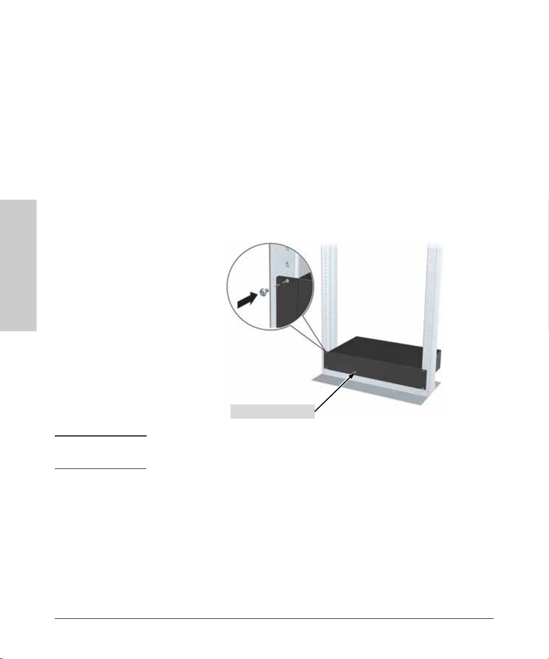
4. (Optional) Install a rack shelf (not provided with your switch) into
position as low as possible in the rack. Make sure that any screws used
to secure the shelf to the rack are securely tightened.
page 2-12) packed with the chassis.
Rack Shelf (Optional)
WARNING Make sure the rack is bolted down to prevent it from becoming
unstable and/or falling over when the chassis is installed.
The chassis will be installed on top of the rack shelf.
2-10
Page 37
Installing the ProCurve Switch 8100fl
Installation Procedures
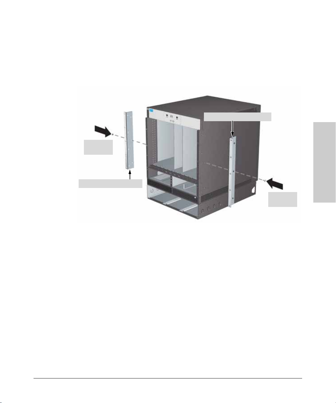
5. The mounting brackets supplied with the switch allow it to be mounted
in different locations relative to the front of the rack (see illustration
below). Attach the brackets on both sides of the chassis for the position
you select.
Be sure to tighten the mounting screws until they are snug. Be careful not
to overtighten them. This can result in damage to the screws or chassis.
Right Rack Mounting Bracket
Installing the ProCurve
Mounting
Screws
Left Rack Mounting Bracket
Switch 8100fl
Mounting
Screws
2-11
Page 38
Switch 8100fl
Installing the ProCurve
Installing the ProCurve Switch 8100fl
Installation Procedures
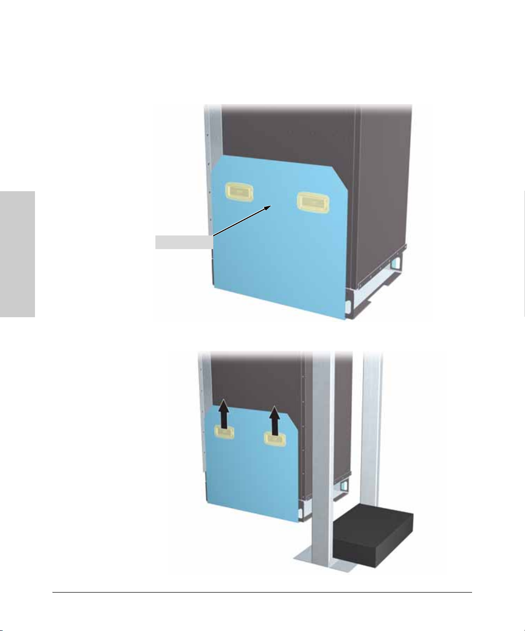
6. Position the chassis in the product sling so that the front of the chassis
lines up with the front edge of the sling (see illustration below). This
allows the back of the chassis to extend over the sling so that it can be
more easily positioned in the rack or on the rack shelf.
Product Sling
2-12
7. With the help of a second person or hand crane, lift the chassis into
position in front of the rack or set its back edge on top of a rack shelf.
Page 39
Installing the ProCurve Switch 8100fl
Installation Procedures
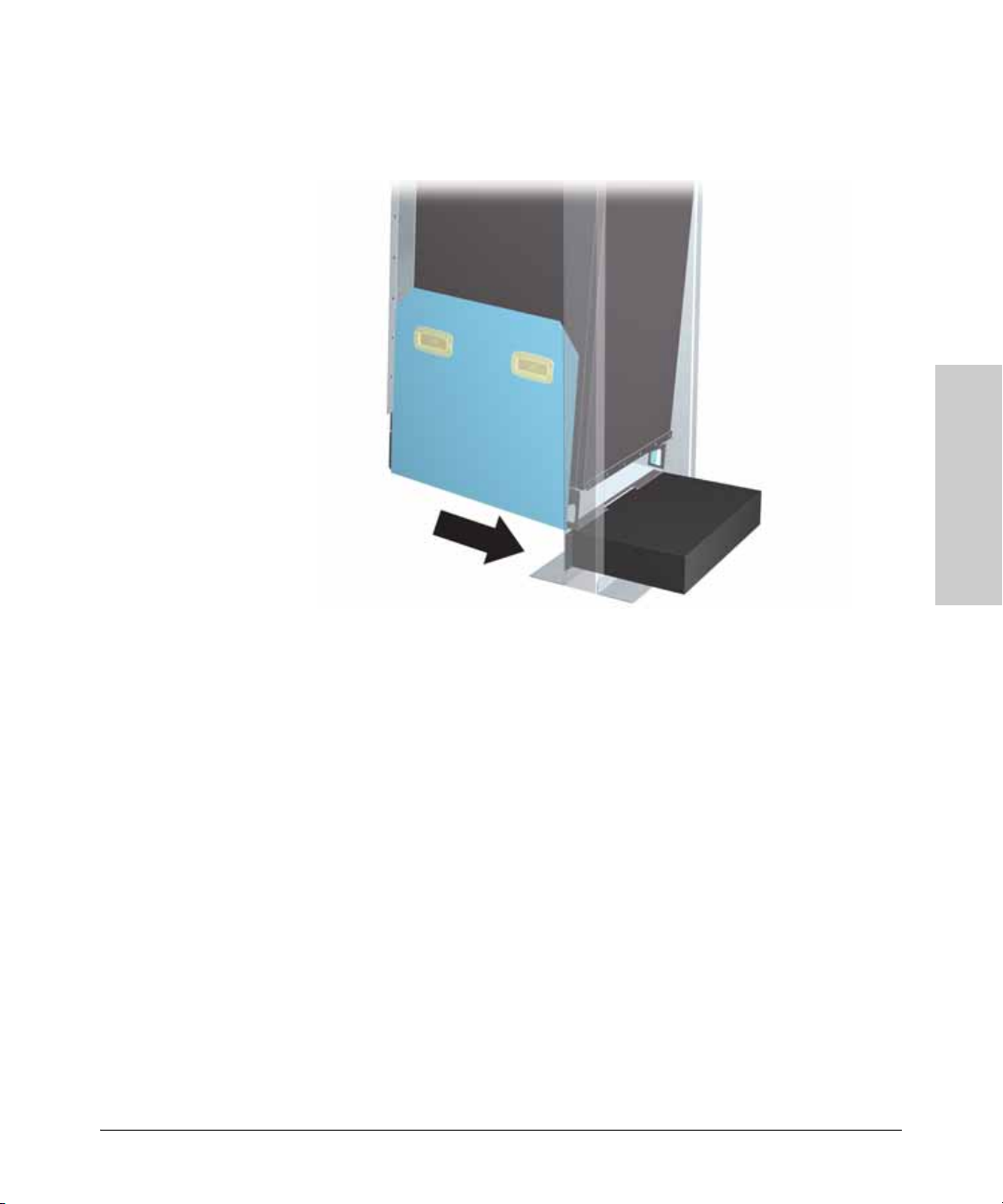
8. With the help of a third person, carefully slide the chassis into the rack
(over the rack shelf, if one is installed) until the mounting brackets touch
the rack and you can remove the product sling.
Installing the ProCurve
Switch 8100fl
The chassis may lean slightly backwards in the rack.
2-13
Page 40
Switch 8100fl
Installing the ProCurve
Installing the ProCurve Switch 8100fl
Installation Procedures
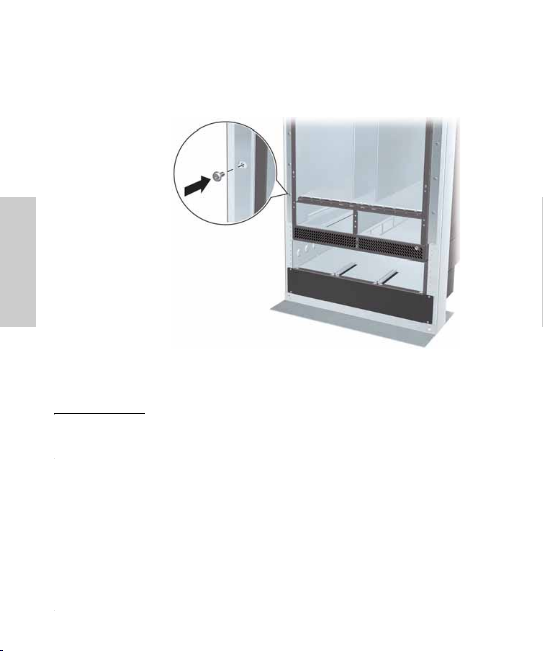
9. While a second person pushes the bottom of the chassis so that the
mounting brackets are flush with the rack, use the appropriate
screwdriver to tighten the screws in the lowest holes of the mounting
brackets on the chassis to the rack.
Continue tightening the screws in the holes on the right and left sides of
the mounting brackets to fix it to the rack, starting with the bottommost
holes and moving upwards.
WARNING All mounting screws must be tightened securely before the chassis can be
loaded with additional hardware. If you accidentally leave the screws
loose, the chassis can slip and fall, possibly causing damage and injury.
2-14
Page 41
Installing the ProCurve Switch 8100fl
Installation Procedures
3. Installing Fan Trays
Each ProCurve Switch 8100fl chassis is shipped with two fan trays to provide
cooling for the modules. Each fan tray assembly is installed below the vertical
slots. The fan tray assembly is hot-swappable so you can replace the assembly
yourself while the switch is powered on.
Note To ensure that the fan tray assembly can provide adequate cooling, always
provide a minimum of 3 inches (7.62 centimeters) of clearance behind the
chassis. Adequate ventilation is provided from the front as long as you
maintain sufficient clearance to add or remove modules.
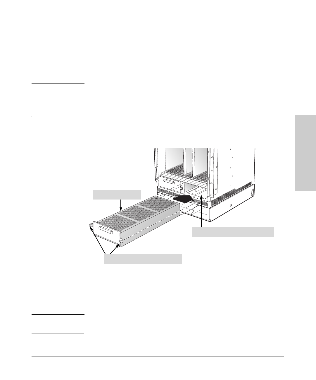
To install a fan tray (5069-7936):
1. Align the fan tray guides with its corresponding slot and push in until the
fan tray mounting plate contacts the chassis frame.
Fan Tray (one of two)
1. Slide fan tray completely into chassis.
2. Tighten retaining screws to secure.
2. Tighten the two screws on each side of the fan tray housing using a slotted
or Phillips screw driver. (Hand tightening the captive screws may not be
sufficient to prevent normal fan vibration from allowing the assembly to
work loose and become disconnected.)
Installing the ProCurve
Switch 8100fl
3. Repeat steps 1 and 2 to install the second fan tray.
Caution If you want to change a fan tray, remove the old tray and insert a new one as
quickly as possible to maintain proper cooling of the chasis.
2-15
Page 42
Switch 8100fl
Installing the ProCurve
Installing the ProCurve Switch 8100fl
Installation Procedures
4. Installing Modules
A ProCurve Switch 8100fl supports three types of modules (shipped separately
from the chassis):
■ Switch fabric modules (half-height modules for the Switch 8108fl;
full-height modules for the Switch 8116fl) are installed in the central slots
labeled FM. Install the primary module in slot FM-A; install the hot
standby module into slot FM-B. (When you install a single switch fabric
module, you can use either slot FM-A or FM-B.)
■ Management modules (thicker, half-height modules) are installed in slots
labeled MM.
• If you are installing only one management module, you can install it
in either slot MM-A or MM-B.
• If you are installing two management modules, the primary
management module is the one installed in slot MM-A. The redundant
management module is the module installed in slot MM-B.
■ Interface modules (narrow half-height modules) are installed in
numbered slots (1-8 on the Switch 8108fl; 1-16 on the Switch 8116fl).
Be sure to install each type of module in its appropriate slot by referring to
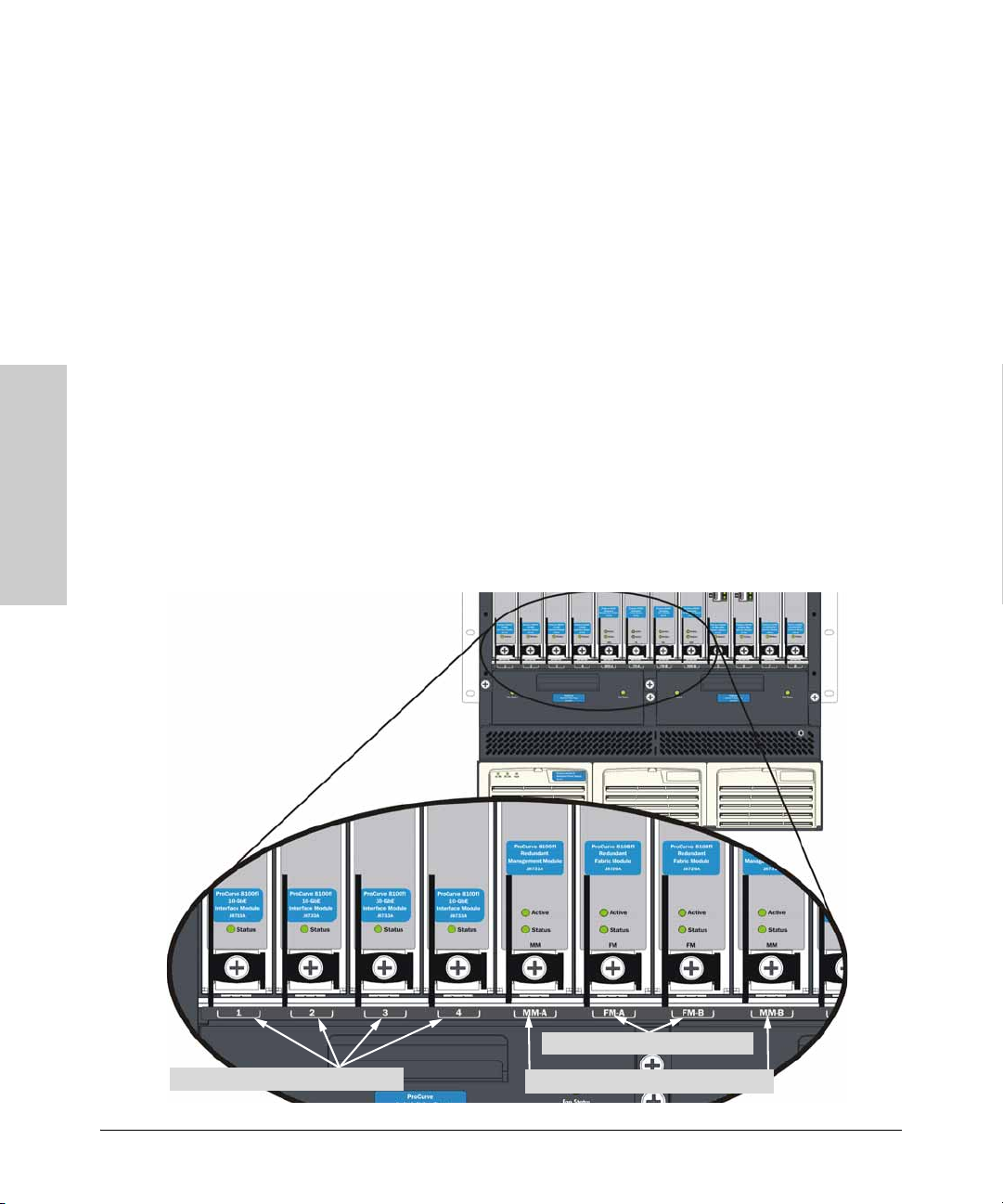
the slot number or label, as shown in the following illustration:
2-16
Numbered slots for interface modules
FM slots for switch fabric modules
MM slots for management modules
Page 43

Installing the ProCurve Switch 8100fl
Installation Procedures
Installation To avoid damaging modules and the backplane, be sure to inse rt the right type
Precautions
of module into the slot type designed for it. If you install a module in the wrong
slot, physical keying prevents the module from fully entering the slot.
■ Avoid damage from static electricity. Static electricity can severely
damage the electronic components on the modules. Follow these
procedures to avoid such damage:
• Use proper ESD grounding procedures before handling modules.
• Handle the module by its bulkhead or edges and avoid touching the
components and the circuitry on the board.
• When installing the module, equalize any static charge difference
between your body and the switch by wearing a grounding wrist strap
and attaching it to the switch’s metal body, or by frequently touching
the switch’s metal body.
■ Ensure you fully insert the modules. That is, press the module into
the slot until the bulkhead on the module is contacting or is very close to
contacting the front face of the switch chassis.
• Do not force a module into its slot. If the module does not seem
to be seating correctly, ease it back out and check alignment. Forcing
a module can damage it and the backplane. Modules are keyed so that
they cannot be fully installed in a wrong slot.
• Check for alignment. Make sure that the metal plate of the module
—not the circuit board—is between the module guides. Check both
the upper and lower guides for proper alignment.
■ Secure the module. Once the module is fully inserted, make sure that
you fully close the ejector levers and screw in the two retaining screws to
secure the module in place.
■ For safe operation, proper switch cooling, and reduction of
electromagnetic emissions, ensure that a slot cover is installed on any
unused module slot. For safety, no more than one slot should be
uncovered at a time when you install a module and while the
switch is powered on.
Installing the ProCurve
Switch 8100fl
Hot Swapping Modules
Modules can be “hot swapped”, that is installed or replaced while the switch
is powered on. The procedures and conditions differ slightly, according to the
type of module. For more information, see
on page 4-4.
“Hot Swapping and Redundancy”
2-17
Page 44

Switch 8100fl
Installing the ProCurve
Installing the ProCurve Switch 8100fl
Installation Procedures
Installing a Switch Fabric Module
A ProCurve Switch 8100fl requires at least one switch fabric module to process
traffic for any interface module. Only one switch fabric module is required for
full throughput.
Note that the 8-slot Switch 8108fl uses the half-height switch fabric module.
The 16-slot Switch 8116fl uses a full-height switch fabric module.
If you are installing two switch fabric modules, the primary switch fabric
module is the one installed in slot FM-A. The redundant switch fabric module
is the module installed in slot FM-B.
Caution To prevent equipment damage, review the installation precautions on page
2-17.
To install a switch fabric module (J8729A or J8730A):
1. If a cover plate is installed in the switch fabric module slot, remove it by
loosening the captive screws (using slotted or P2 Phillips screwdriver)
and pulling the ejectors.
2. Open the ejectors at the top and bottom of the module, and hold the upper
ejector lever in the unlocked position while you are installing the module
(see step 1 in the illustration opposite).
3. Position the switch fabric module in the FM-A slot (for primary module)
or FM-B slot (for redundant module). (You can use either slot in a single
switch fabric module installation.)
4. Slide the switch fabric module all the way into the slot, firmly but gently
pressing to make sure that the pins on the back of the module are
completely seated in the backplane.
Caution The 8116fl switch fabric module is a double height module, which makes
it heavier than the other modules. Make sure that the module is properly
seated when you insert it in the switch chassis.
Make sure that the metal plate of the module, and not the circuit board,
is between the guides. Check both the upper and lower guides for proper
alignment.
Do not force a module into its slot. If the module does not seem to be
seating correctly, ease it back out and check alignment. Forcing a module
can damage it and the chassis.
5. To lock the module into the slot, close the ejectors until they are vertical.
2-18
Page 45
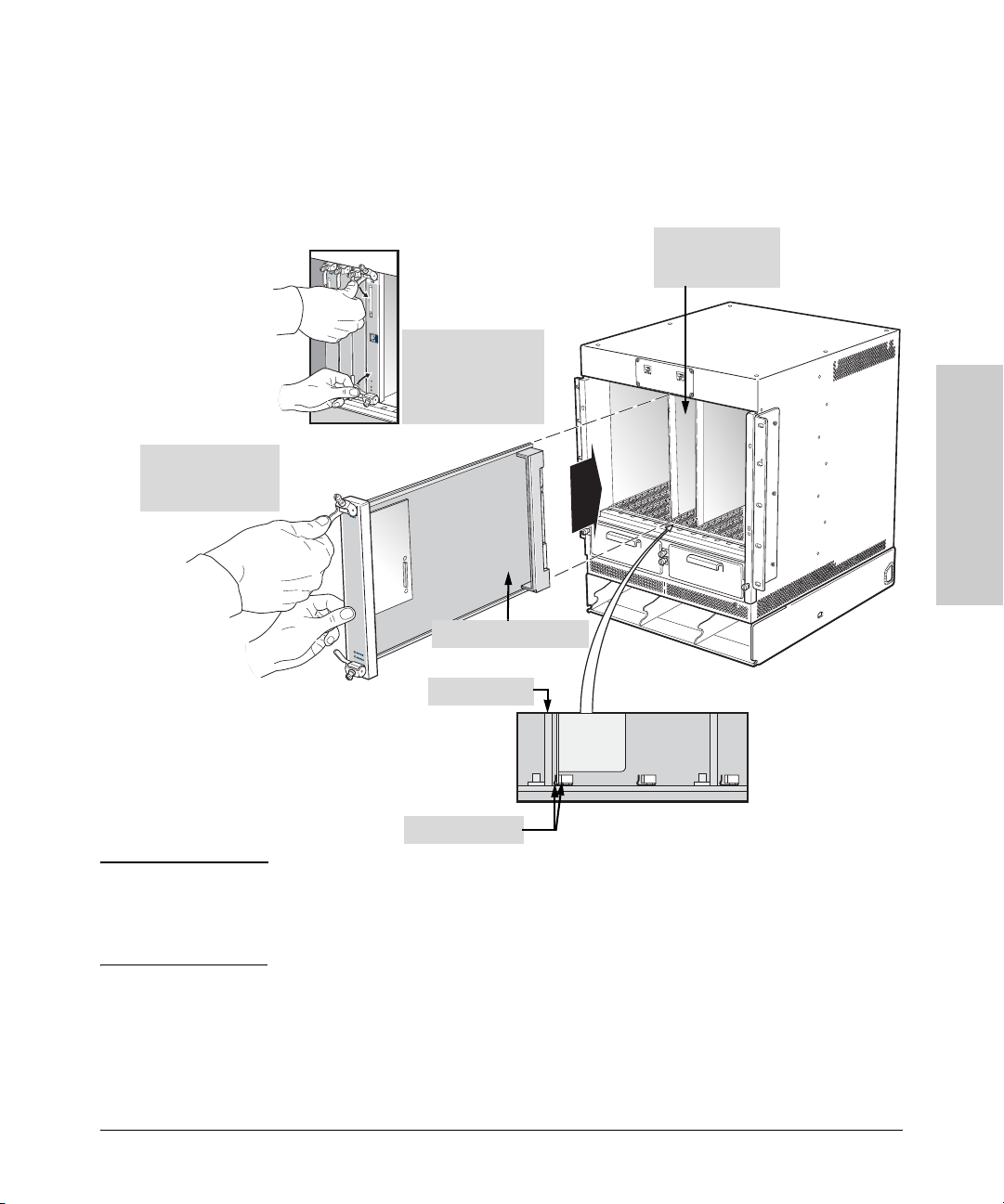
1. Hold upper ejector
lever out to keep in
unlocked position.
Installing the ProCurve Switch 8100fl
6.
Tighten the captive screw on each ejector by hand and seat with a screw
Installation Procedures
driver to keep the module from being removed accidentally. Do not
overtighten the captive screws.
2. Install switch
fabric modules in
two center slots.
3. Rotate ejectors to
lock the module in
place, and then
tighten the captive
screws.
Installing the ProCurve
Switch 8100fl
Caution
Switch Fabric Module
Metal Plate
Module Guides
The module must be fully seated and the ejectors fully locked (vertical)
before the captive screws will align properly. Also, fully seating the
module ensures proper contact of the card with the backplane which is
necessary for optimal performance.
7.
Repeat steps 1 to 6 to install a second switch fabric module to provide full
(100%) redundancy in the event of a failure of the primary module.
2-19
Page 46

Installing the ProCurve Switch 8100fl
Installation Procedures
Installing a Management Module
The management module is the main processing unit of a ProCurve Switch
8100fl and is required for the unit to operate. It contains system-wide bridging
and routing tables, and runs the main control protocols.
In addition to a slot for the primary management module, the chassis also has
a slot for a second (optional) redundant management module:
■ If you are installing only one management module, you can install it in
either slot MM-A or MM-B.
■ If you are installing two management modules, the primary management
module is the one installed in slot MM-A. The redundant management
module is the module installed in slot MM-B.
Caution To prevent equipment damage, be sure to follow the installation precautions
on
page 2-17.
To install a management module (J8731A):
Switch 8100fl
Installing the ProCurve
1. If a cover plate is installed in the management module slot MM-A or
MM-B, remove the cover plate: loosen the captive screws on the ejectors
until the screws pop out, then open the ejectors and pull out the plate.
2. Open the ejectors at the top and bottom of the module, and hold the upper
ejector lever in the unlocked position while you are installing the module
(see step 1 in the illustration opposite).
3. Align the metal plate of the management module with the guides at the
top and the bottom of the slot opening, as shown in the illustration on the
next page.
Caution Make sure that the metal plate of the management module, and not the
circuit board, is between the module guides. Check both the upper and
lower guides.
Do not force a module into its slot. If the module does not seem to be
seating correctly, ease it back out and check alignment. Forcing a module
can damage it and the chassis.
4. Slide the management module all the way into the slot, firmly but gently
pressing to make sure that the pins on the back of the management module
are completely seated in the backplane.
5. To lock the module into the slot, close the ejectors until they are vertical.
2-20
Page 47
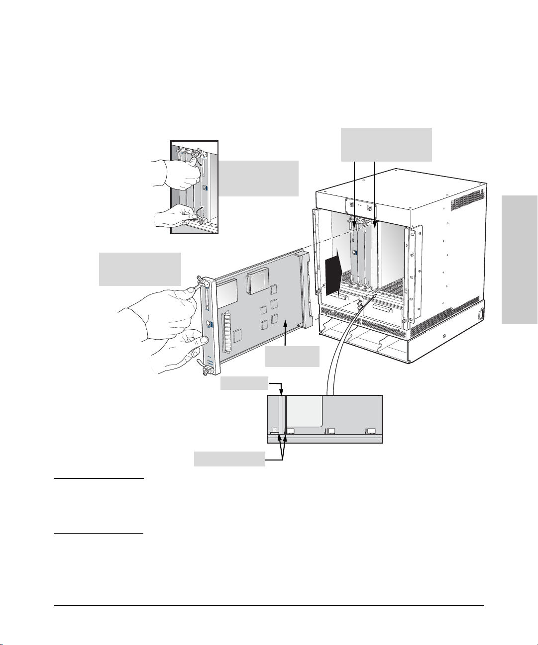
6. Tighten the captive screw on each ejector by hand and seat with a screw
1. Pull out upper ejector
lever to hold it in
unlocked position.
Installing the ProCurve Switch 8100fl
Installation Procedures
driver to keep the module from being removed accidentally. Do not
overtighten the captive screws. (You can tighten the thumb screws with
a P2 Phillips screwdriver to eliminate the possibility of casual removal by
unauthorized personnel.)
2. Install management
modules on either side
of the two central slots.
3. Push in ejectors in to
secure and tighten
captive screws.
Installing the ProCurve
Switch 8100fl
Management
Module
Metal Plate
Module Guides
Caution The management module must be fully seated and the ejectors fully
locked (vertical) before the captive screws will align properly. Also, fully
seating the card ensures proper contact of the card with the backplane
which is necessary for optimal performance.
7. Repeat steps 1 to 6 to install a secondary management module to provide
full (100%) redundancy in the event of a failure of the primary module.
2-21
Page 48

Switch 8100fl
Installing the ProCurve
Installing the ProCurve Switch 8100fl
Installation Procedures
Installing an Interface Module
ProCurve 8100fl switches provide non-blocking throughput regardless of the
software features you are using. Therefore, you do not need to “load balance”
interface modules by placing them in certain physical relationships to balance
the load on the backplane. Regardless of where you install the interface
modules, the backplane can provide full, non-blocking throughput.
You can install interface modules in any numbered slot (1–8 on the Switch
8108fl and 1–16 on the Switch 8116fl). The illustration on
example of how to install an interface module.
To install an interface module (J8733A, J8734A, or J8735A):
Caution To prevent equipment damage, review the installation precautions on page
2-17.
1. If a cover plate is installed in the interface module slot, remove the cover
plate: loosen the screws on the ejectors, then open the ejectors and pull
out the plate.
2. Open the ejectors at the top and bottom of the module, and hold the upper
ejector lever in the unlocked position while you are installing the module
(see step 1 in the illustration opposite).
page 2-23 shows an
3. Align the metal plate of the interface module between the module guides,
as shown in the illustration.
Caution Make sure that the metal plate of the interface module, and not the circuit
board, is between the module guides. Check both the upper and lower
guides.
Do not force a module into its slot. If the module does not seem to be
seating correctly, ease it back out and check alignment. Forcing a module
can damage it and the chassis.
4. Slide the interface module all the way into the slot, firmly but gently
pressing the interface module in place to make sure that the pins on the
back of the interface module are completely seated in the backplane.
5. To lock the module into the slot, close the ejectors until they are vertical.
2-22
Page 49
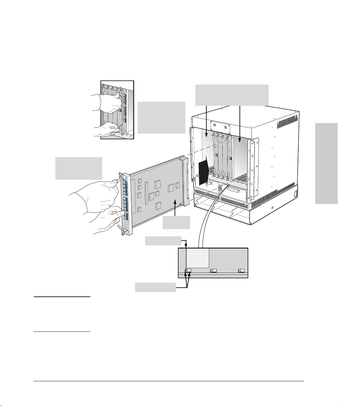
1. Hold upper ejector
lever out to keep in
unlocked position.
Installing the ProCurve Switch 8100fl
6.
Tighten the captive screw on each ejector by hand and seat with a screw
Installation Procedures
driver to keep the module from being removed accidentally. Do not
overtighten the captive screws. (You can tighten the thumb screws with
a P2 Phillips screwdriver to eliminate the possibility of casual removal by
unauthorized personnel.)
2. Install interface modules in any
of the numbered slots on the left
3. Rotate ejectors to
lock the module in
place, and then
tighten the captive
screws.
and right side of the chassis.
Installing the ProCurve
Switch 8100fl
Caution
Interface
Module
Metal Plate
Module Guides
The interface module must be fully seated and the ejectors fully locked
(vertical) before the captive screws will align properly. Also, fully seating
the card ensures proper contact of the module with the backplane which
is necessary for optimal performance.
7.
Repeat steps 1 to 6 to install any additional interface modules.
2-23
Page 50

Switch 8100fl
Installing the ProCurve
Installing the ProCurve Switch 8100fl
Installation Procedures
5. Installing AC Power Supplies
The Switch 8108fl is shipped with a single AC power supply; the Switch 8116fl
is shipped with two AC power supplies. Extra slots are provided in the front
of each chassis for the use of additional (optional) redundant power supplies:
one in the Switch 8108fl and two in the Switch 8116fl.
This section explains how to install one or more AC power supplies in the
chassis. It is recommended that you complete installation of the switch
modules before turning the power on to verify the installation (see
Cautions Observe the following precautions when installing a power supply in your
switch:
■ Take into consideration the ratings on power supplies when connecting
them to your supply circuits. Overloading circuits can destroy overcurrent
protection as well as supply wiring.
■ Use a single-phase grounded AC power source located within 6 feet (1.89
meters) of the installation site.
■ Use only certified and suitable power cables and plug assemblies for your
location.
■ Do not cover the power supply inlet or exhaust vent.
■ High leakage current can be caused by multiple power supplies. For this
reason, it is essential that each power cable be connected to separate
branch circuits with proper earth connections.
page 2-29).
2-24
Page 51
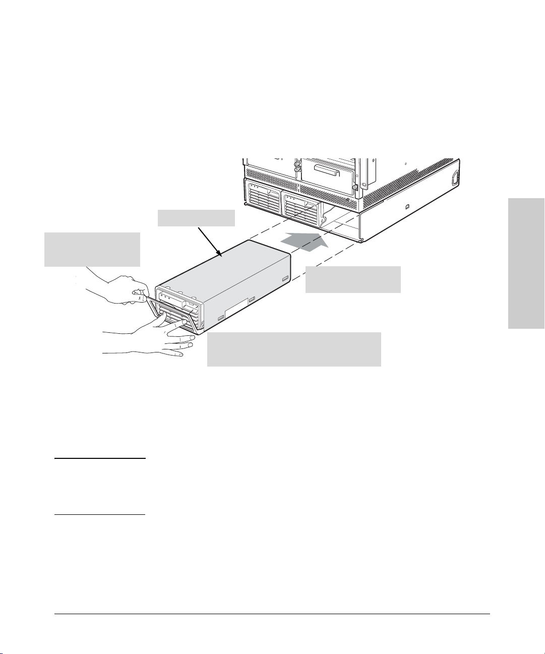
Installing the ProCurve Switch 8100fl
Installation Procedures
To install an AC power supply (J8732A):
1. Insert a flat blade screwdriver (or similar lever device) into the indent
located on the bottom edge in the center of the handle. Gently turn the
screwdriver with the handle downward and lower the power supply
handle to its fully extended position.
2. Position the power supply between the guides in an open power supply
slot.
AC Power Supply
1. Lower the power supply
handle to an approximate
45 degree angle.
2. Slide power supply
completely into chassis
3. To lock the power supply in place, adjust the
handle position at the edge of the chassis, and then
rotate the handle upwards to engage retaining
3. Slide the AC power supply all the way into the slot, firmly but gently
pressing to make sure that the connectors on the back of the power supply
are completely seated in the backplane.
4. Push the handle up and flush with the power supply chassis. The handle
should snap into place, locking the power supply into position.
Caution If the handle does not snap into a vertical position, do not force it. You
may need to re-insert the power supply, taking care to adjust the handle
position during the final few centimeters to successfully engage the
retaining latch.
Installing the ProCurve
Switch 8100fl
2-25
Page 52
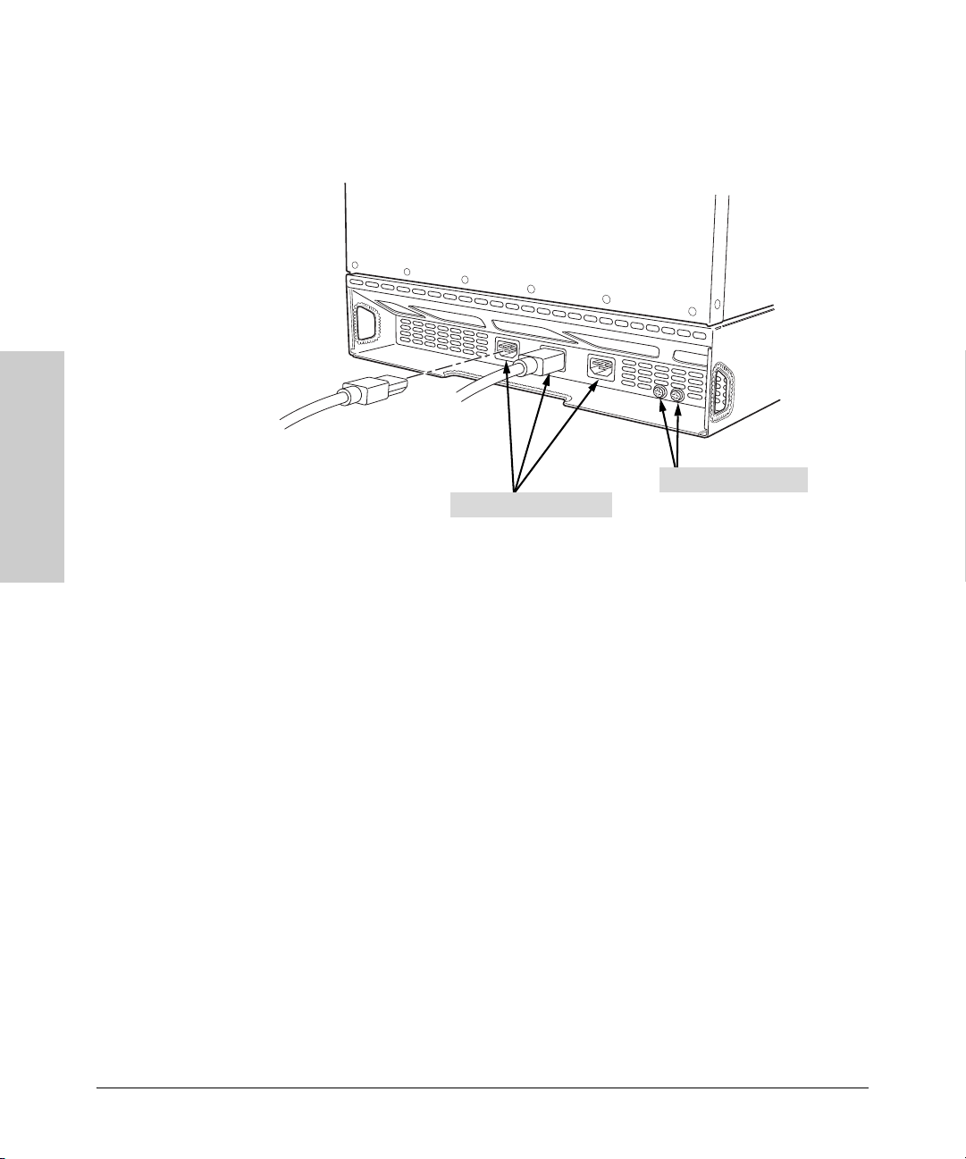
Installing the ProCurve Switch 8100fl
Installation Procedures
Switch 8100fl
5. Attach the power cable to the corresponding AC outlet from the rear, side,
or bottom of the chassis as your installation requires (see the following
illustration).
Grounding Screws
AC Power Receptacles
Installing the ProCurve
To provide strain relief for a power cable, tie wrap the cable to the access
opening on the side of the chassis or to the rack.
6. Repeat steps 1 to 5 to install an additional power supply.
2-26
Page 53

Installing the ProCurve Switch 8100fl
Installation Procedures
6. Connecting a Console to the Switch
ProCurve 8100fl switches have a console interface for managing and
configuring the switch. The console can be accessed via the following
methods.
■ Out-of-band: Connect a PC or VT-100 terminal directly to the switch
using the RJ-45 to DB-9 adapter and straight-through cable that comes
with each ProCurve Switch 8100fl. For console access, you can directly
connect to the RJ-45 serial port on the top of the switch chassis or connect
through a Telnet session to the 10/100Base-T Ethernet port on the
management module. (The 10/100Base-T Ethernet port requires initial
configuration. Refer to the Management and Configuration Guide for
detailed information.)
■ In-band: Manage the switch using a Telnet session from a workstation on
your network with a VT-100 terminal emulator. This method requires that
you configure the switch with an IP address and a subnet mask by using
either out-of-band console access or through DHCP/Bootp.
ProCurve 8100fl switches can support simultaneous out-of-band console and
in-band Telnet sessions.
Terminal Configuration
Installing the ProCurve
Switch 8100fl
To connect a console to the switch, configure the PC terminal emulator as a
VT-100 or ANSI terminal, or use a VT-100 terminal and configure it to operate
with the following settings:
■ Baud rate set to 9600
■ 8 data bits, 1 stop bit, no parity, and flow control set to None
■ For the Windows Terminal program, disable (uncheck) the “Use Function,
Arrow, and
■ For the Hilgrave HyperTerminal program, select the “Terminal keys”
Ctrl Keys for Windows” option.
option for the “Function, arrow, and ctrl keys act as” parameter.
If you want to operate the console using a different configuration, ensure you
change the settings on both the terminal and on the switch. Change the switch
settings first, then change the terminal settings, and re-establish the console
session.
2-27
Page 54
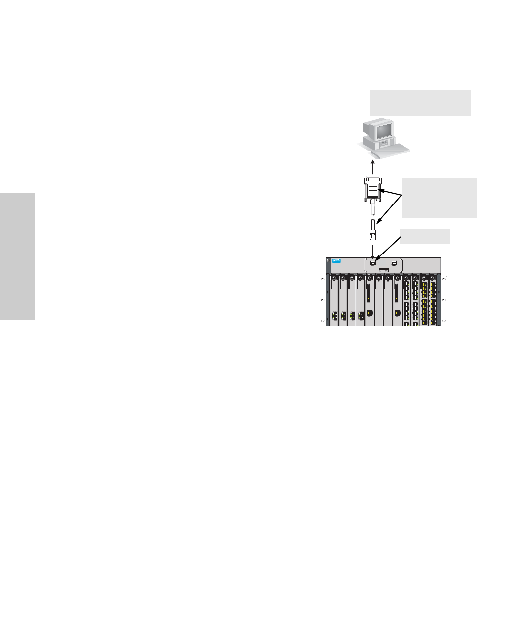
Installing the ProCurve Switch 8100fl
h
Installation Procedures
Direct Console Access
To connect a console to the switch,
follow these steps:
1. Connect the PC or terminal to
the switch’s RJ-45 console port
using the RJ-45 to DB-9 adapter
and straight-through cable
included with the switch. (If
your PC or terminal has a 25-pin
serial connector, first attach a 9pin to 25-pin straight-through
adapter to the PC end of the
console cable.)
2. Turn on the terminal or the PC
power. If you are using a PC,
start the PC terminal program.
PC running a terminal emulator
program, or a VT-100 terminal
RJ-45 to DB-9 adapter
and straight-through
cable (Maximum lengt
25 ft.)
Console port
Switch 8100fl
Installing the ProCurve
3. Press the Enter key two or three
times and you will see the
copyright page and the message
“Press any key to continue”.
Press a key, and you will then see
the switch console CLI prompt.
Telnet Console Access
To access the switch through a Telnet session, follow these steps:
1. Ensure the switch is configured with an IP address (as described in
“Setting the Management Module IP Address” on page 3-2) and that the
switch is reachable from the Telnet workstation (for example by using a
Ping command to the switch’s IP address).
2. Start the Telnet program and connect to the switch’s IP address.
3. You will see the copyright page and the message “Press any key to
continue”. Press a key, and you will then see the switch console CLI
prompt.
If you want to continue with console management of the switch at this time
through either a direct connection or a telnet session, see
Started With Switch Configuration” for the basic configuration steps. For
more detailed information, refer to the Management and Configuration
Guide on the Documentation CD-ROM that comes with your switch.
Chapter 3, “Getting
2-28
Page 55
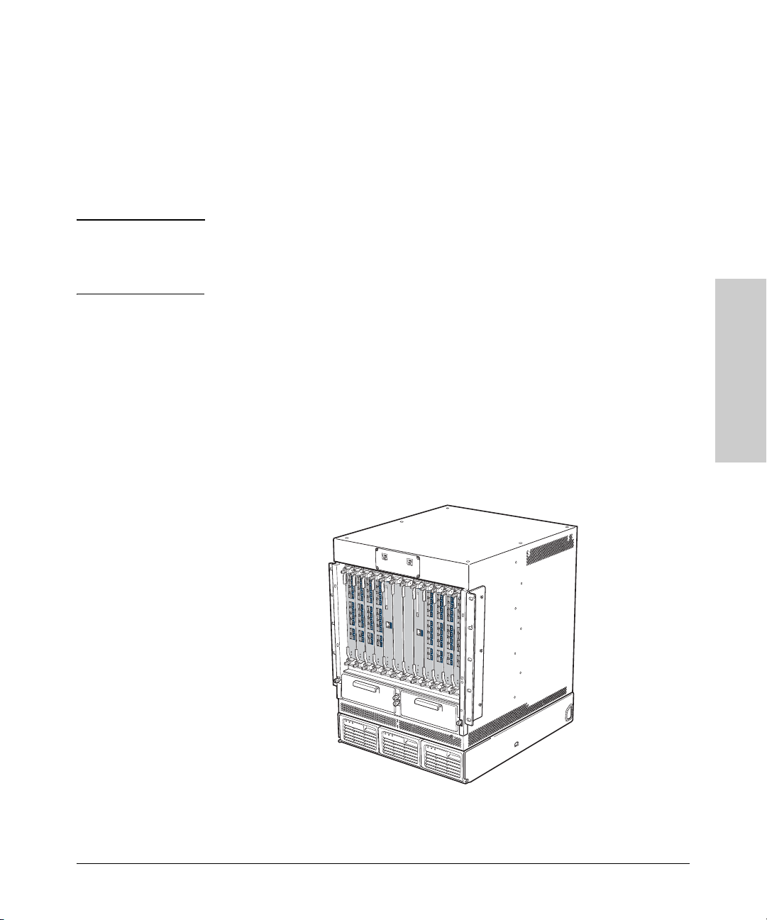
Installing the ProCurve Switch 8100fl
Installation Procedures
7. Verifying the Installation
After you have installed all the appropriate components for your switch
(power supplies, fan trays, and the various modules required for your
installation), replace the power and slot covers over any empty power bays
and module slots. Then power on the switch to verify that it is working
properly by following the procedure described on
Caution For proper switch cooling and to reduce any electronic emissions, install the
appropriate slot covers over any unused power bays and module slots.
Failure to use the correct slot cover may result in improper switch cooling.
Make sure that you use the correct type of cover for each empty slot. Each
cover is labeled as follows to indicate the type of slot for which it is designed
(part numbers shown in parentheses):
■ FM Cover for Switch 8008fl fabric module slots (5069-0122)
■ FM Cover for Switch 8016fl fabric module slots (5069-7937)
■ MM Cover for management module slots (5069-0123)
■ IM Cover for interface module slots (5069-0124)
■ EM Cover for Switch 8116fl expansion module slots (5069-0125)
page 2-30.
Installing the ProCurve
Switch 8100fl
The following illustration shows a fully loaded Switch 8108fl chassis:
2-29
Page 56

Switch 8100fl
Installing the ProCurve
Installing the ProCurve Switch 8100fl
Installation Procedures
To verify the installation:
1. Make sure all exposed interface module slots and power supply bays are
free of foreign objects, such as tools, and have the correct slot covers.
2. Check the power supplies to make sure they are attached to your power
source.
3. Connect an active terminal or a PC running terminal emulation software
to the console port on the switch chassis (labelled Console for MM-A
or Console for MM-B) for the active management module (see
page 2-27
for details). The active management module (MM-A or MM-B) has its
Active LED lit (green).
4. Verify proper operation by observing the LEDs. Make sure the LED on
each power supply and fan tray assembly is a solid green. Also, make sure
that the Status LED on each active module is solid green.
Notes on LEDs ■ The Link and Activity LEDs on the X2 10-GbE modules (J8736A and
J8737A) will go on for two seconds when a transceiver is inserted into
the port. They will then go off until a network cable is plugged into the
transceiver and the LEDs follow their normal operational behavior (see
page 1-11).
■ The Activity LED on the 1-Port 10-GbE LR Module (J8733A) will flash once
every four seconds. This is a safety feature known as Auto Laser Shut
down.
■ The Link Status LED for the ports on the 10-Port 100/1000Base-T Module
(J8734A) will show solid green when a port is connected at 1000 Mbps,
and solid amber when a port is connected at 100 Mbps.
-
2-30
For more details on specific LED conditions, see “LEDs” on page 1-6.
Page 57

Installing the ProCurve Switch 8100fl
Installation Procedures
8. Connecting Network Devices
Using the appropriate network cables, connect other switches, routers,
computers, servers, printers, and other network devices to the switch ports.
The type of network connections that you need to use depends on the types
of interface modules you have installed:
■ The X2 10-GbE modules (J8736A and J8737A) support both copper and
fiber optic connections that require the use of a transceiver (see
or Removing Transceivers and Connecting Cables” on page 4-9).
■ The 10-Port Mini-GBIC module supports fiber optic connections that
require the use of mini-GBICs (see
“Installing mini-GBICs” on page 4-15).
“Installing
In general for all the modules, when a network cable from an active network
device is connected to the switch, the Link LED for the switch port should go
on (see
“LEDs” on page 1-6 for details). If the Link LED does not go on, refer
to the following table for diagnostic tips and troubleshooting procedures.
Table 2-1. Troubleshooting the Link LED
Condition Diagnostic Tip
Port Link LED is • For the indicated port, verify that both ends of the cabling (at the switch and the connected
off when a cable is
connected
device) are securely connected.
• Verify that the connected device and switch are both powered on and operating correctly.
• Verify that you have used the correct cable type for the connection (for more information on
cables, see Appendix B, “Switch Ports and Network Cables”).
• For fiber-optic connections, verify that the transmit port on the switch is connected to
the receive port on the connected device, and the switch receive port is connected to
the transmit port on the connected device.
• Verify that the connection parameters in the configurations of the switch port and the
connected device match. Mismatched configurations are a frequent cause of connection
problems.
You can use the console interface (or if you have configured an IP address on the switch, use
a Telnet session) to determine the state and configuration of the port and re-enable the port
if necessary.
• If the above procedures do not resolve the problem, try using a different port or a different
cable.
Installing the ProCurve
Switch 8100fl
2-31
Page 58
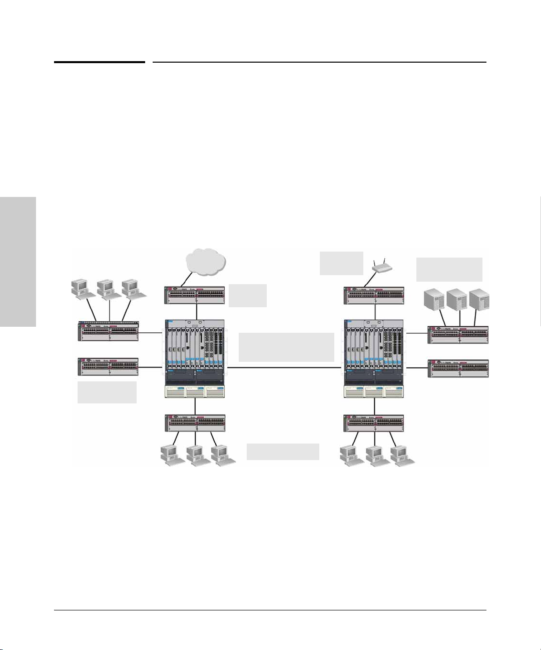
Installing the ProCurve Switch 8100fl
Sample Network Topologies
Sample Network Topologies
This section provides examples of network topologies in which ProCurve
8100fl switches can be implemented.
Connecting ProCurve Intelligent EDGE Devices
The ProCurve 8100fl Switch Interconnect Fabric provides a highly available,
high performance, forwarding fabric for interconnecting intelligent edge
devices. The ProCurve Switch 8100fl series provides an alternative to
traditional core routing switches by combining low cost and complexity with
high availability, resiliency, and forwarding capacity.
Switch 8100fl
Installing the ProCurve
Intelligent Edge
Switches
Wireless
Clients
WAN
Router
ProCurve 8100fl Switches
connected by a 10GbE
Link
PCs and peripherals
Servers connected
by Gigabit links
The 8100fl architecture is designed for ultra-high availability and resiliency
within a single chassis, with attributes such as redundant management,
redundant switch fabric, graceful degradation, and features such as spanning
tree, VRRP, and OSPF.
2-32
Page 59
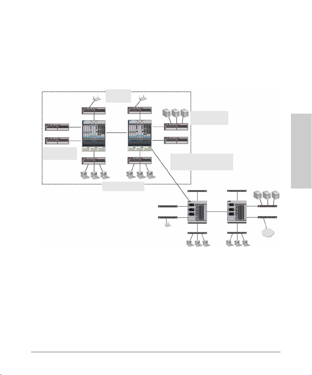
Intelligent Edge
Switches
Installing the ProCurve Switch 8100fl
Sample Network Topologies
Expanding Your Network
The ProCurve 8100fl Switch Series can be integrated into an existing
traditional network to supplement existing bandwidth, while providing a clear
migration path to an optimized ProCurve Adaptive EDGE Architecture. The
illustration below shows a ProCurve 8100fl switch connected to a traditional
core network using a 10 GbE link for maximum throughput.
Wireless
Clients
Servers connected
by Gigabit links
ProCurve 8100fl Switches
Connected to Core Routers
by a 10GbE Link
Installing the ProCurve
Switch 8100fl
PCs and peripherals
ProCurve 8100fl switches can extend the traditional core network by
providing additional bandwidth and decision-making capabilities at the edge
of the network. PCs, printers and other peripherals, and servers can be interconnected via intelligent edge switches.
2-33
Page 60

— This page is intentionally unused. —
Page 61

Getting Started With Switch Configuration
This chapter is a guide for using the command line interface (CLI) via a direct
console to quickly assign an IP address and subnet mask to the switch, set a
Manager password, and, optionally, configure other basic features.
Topics covered in this chapter include:
■ Accessing the CLI (see page 3-1)
■ Setting Basic System Information (see page 3-2)
■ Setting up Passwords (see page 3-6)
■ Updating Software (see page 3-10)
Note Many other features can be configured through the CLI to optimize the
switch’s performance, enhance your control of network traffic, and improve
security. Once an IP address has been configured on the switch, these features
can be accessed more conveniently through a remote Telnet session. For more
information, refer to the Management and Configuration Guide which is on
the Documentation CD-ROM that came with your switch.
3
Booting Up and Accessing the CLI
1. Connect a terminal device to the switch as described on page 2-27.
2. Power on the switch by either inserting the power supplies or turning on
the AC to the power supplies.
3. At the prompt, press Enter to activate the Command Line Interface (CLI)
on the console.
Note If the boot sequence stops and the CLI presents a bootrom prompt
(PMON>), call ProCurve Networking technical support.
4. From the Exec mode prompt (for example, Switch 8100fl>) type enable and
press Enter.
The prompt will change to the Privileged Exec prompt (Switch 8100fl#)
and you now have full access to the CLI. (For information on all of the CLI
modes, refer to the Management and Configuration Guide.)
Getting Started With Switch
Configuration
3-1
Page 62

Getting Started With Switch Configuration
Setting Basic System Information
Setting Basic System Information
The first, and only essential, task in basic system configuration is assigning a
Management IP address to the switch. This is the IP address that you use to
access the ProCurve Switch 8100fl on the network. You must enable the
management port and you must enable telnet in order to access the switch
remotely.
Follow the procedures in this section to set the following system information:
■ IP address for the management port on the management module
■ System time and date
■ System name
■ System location
■ Contact name (the person to contact regarding this switch)
■ Log in banners
Notes This section assumes a basic understanding of CLI commands, modes, and
procedures. For more detailed information, refer to the Management and
Configuration Guide on the Documentation CD-ROM that comes with your
switch.
Getting Started With Switch
The running configuration remains in effect only during the current power
cycle. If you power off or reboot the switch without saving the running
configuration changes to the Startup configuration file, the changes are lost.
For details on savings your configuration, refer to
“Saving and Using the New
Configuration” on page 3-4.
Configuration
Setting the Management Module IP Address
To set the system IP address and enable Telnet access to the switch:
1. From the Exec (>) prompt, enter the enable command to get to the
Privileged Exec mode in the CLI.
2. From Privileged Exec mode, enter the configure command to get to
Configuration mode.
3. From Configuration mode, enter the following command:
Switch 8100fl(config)#interface management0
3-2
Page 63

Getting Started With Switch Configuration
Setting Basic System Information
Not e
The management0 interface is created automatically by the system and is
reserved for the management port on the management module.
4.
From Interface Management mode, enter the following command:
Switch 8100fl(config-interface-management)#ip address
<ipaddr>
where <ipaddr> is the IPv4 unicast address and subnet mask you assign
to the switch. You can specify the subnet mask in terms of mask bits.
For example:
ip address 10.10.1.45 255.255.248.0
You can also specify the subnet mask in terms of mask length.
For example:
ip address 10.10.1.45/21
5.
Enable the management port, by entering the following command:
Switch 8100fl(config-interface-management)#no shutdown
Here is an example, showing all of the preceding steps:
Switch 8100fl>enable
Switch 8100fl#configure
Switch 8100fl(config)#interface management0
Switch 8100fl(config-interface-management)#ip address
10.10.1.45 255.255.248.0
Switch 8100fl(config-interface-management)#no shutdown
Getting Started With Switch
Configuration
6. From Configuration mode, enter the following commands to enable telnet
on the switch:
Switch 8100fl(config)#ip telnet
Switch 8100fl(config-telnet)#no shutdown
7. Enable a terminal line to the switch by entering:
Switch 8100fl(config)#line vty 0
where 0 represents the vty terminal line connection.
Note The ProCurve Switch 8100fl supports up to 10 vty connections for a maximum
of ten incoming remote connections, plus one console connection.
3-3
Page 64

Getting Started With Switch Configuration
Setting Basic System Information
Saving and Using the New Configuration
To apply the system commands entered in the previous steps to the startup
configuration, follow the steps below:
1. To display the running configuration, enter the following command:
Switch 8100fl(config)#show running
For example:
Switch 8100fl(config)#show running
!
interface Management0
no shutdown
ip address 10.10.1.45/21
!
ip telnet
no shutdown
!
line vty 0
!
line vty 1
!
line vty 2
!
end
Getting Started With Switch
2. To save the configuration changes from the running configuration to the
startup configuration file, enter the write memory command:
Switch 8100fl(config)#write memory
The switch reinstates all configuration changes for the next reboot.
Configuration
Setting the System Date and Time
To set the system date and time:
1. From the Privileged Exec mode (#) prompt, enter the clock set command:
Switch 8100fl#clock set <HH:MM:SS> <1...31> <month> <year>
2. To verify your settings, enter the show clock command:
Switch 8100fl#show clock
3-4
Page 65
Getting Started With Switch Configuration
Setting Basic System Information
The following example shows how to set the clock to 10:45:29 AM PST on
June 30, 2005, and then verify the settings:
Switch 8100fl#clock set 18:45:29 30 june 2005
Switch 8100fl#show clock
*18:45:29 UTC Tues June30 2005
Setting System Parameters
The following commands can be entered only from Configuration mode.
Setting the Host Name
To set the system name, enter the following command:
Switch 8100fl(config)#hostname
For example, to enter the hostname “PNB8108”, type the following:
Switch 8100fl(config)#hostname PNB8108
Setting System ID, Location, and Contact
To assign a chassis ID, a physical location, and a contact person to the system
using snmp (Simple Network Management Protocol), enter the following
commands:
Switch 8100fl(config)#snmp location <string>
Switch 8100fl(config)#snmp chassis-id <string>
Switch 8100fl(config)#snmp contact <string>
where <string> represents the text you enter to specify the location, chassis
identity, and contact support information for the switch.
For additional information about configuring SNMP, refer to the Management
and Configuration Guide.
Getting Started With Switch
Configuration
3-5
Page 66

Getting Started With Switch Configuration
Setting Up Passwords
Setting Up Passwords
You can password-protect CLI access to the Series 8100fl Switch by setting
up passwords for Exec mode access, Privileged Exec mode access, and
terminal line access. If you have a User password but not an Enable password,
you can use only the commands available in Exec mode. If you have an Enable
password, you can use commands available in the Privileged Exec and
Configuration modes, as well as the commands in Exec mode.
In addition, you can set up the Series 8100fl Switch for TACACS+ or RADIUS
authentication by a TACACS+ or RADIUS server. Procedures for configuring
the switch for TACACS+ and RADIUS can be found in the Management and
Configuration Guide.
Specifying the CLI-level Password
To add password protection to the CLI, enter the following command:
Switch 8100fl(config)#enable secret <password>
Getting Started With Switch
By default the password you enter will be encrypted to prevent it from being
displayed in clear text in the configuration file output.
For example:
To create an encrypted password called “mysecretpassword” enter;
Switch 8100fl(config)#enable secret mysecretpassword
Configuration
When you enter the password, and then enter show running-config, this
will appear as a line in the running configuration as follows:
enable secret 5 $1$ZyK.$8NHx2DJBsiGQyhTBmUakz1
where 5 indicates that the password is encrypted as an MD5 hash.
To allow passwords to be displayed in an unencrypted format, enter 0 before
you enter the password.
For example:
To create a clear text password called “mypassword” enter;
Switch 8100fl(config)#enable secret 0 mypassword
3-6
Page 67

Getting Started With Switch Configuration
Setting Up Passwords
When you enter this setting, it will appear as a line in the running
configuration as follows:
enable secret 0 mypassword
where 0 indicates that the password is not encrypted.
Caution Test all new passwords before saving the running configuration to the Startup
configuration file.
After password protecting access to the CLI, you can still access the Series
8100fl Switch without a password by connecting a terminal line configured
without password protection. To password protect terminal lines from users
connecting with Telnet or SSH, see
“Specifying Line-level Passwords”.
Specifying Line-level Passwords
The ProCurve Switch 8100fl supports up to 10 vty remote connections for
which you can assign line-level passwords. To prevent unauthorized access,
it is recommended you assign line-level password protection to all the terminal
lines that you configure.
To add password protection to each terminal (or console) line:
1. From Configuration mode, enter the following command:
Switch 8100fl(config)#line vty 0
where 0 represents the line number of the vty terminal line connection.
2. Enter the following command to configure a password to the line that you
have specified:
Switch 8100fl(config-line)#password <password>
By default the password you enter will be encrypted to prevent it from
being displayed in the configuration file output.
For example:
To create an encrypted password called “mysecretpassword” enter;
Switch 8100fl(config-line)#password mysecretpassword
When you enter the password and then enter show running-config, this
will appear as a line in the running configuration as follows:
password 5 $1$ZyK.$8NHx2DJBsiGQyhTBmUakz1
Getting Started With Switch
Configuration
3-7
Page 68

Getting Started With Switch Configuration
Setting Up Passwords
where 5 indicates that the password is encrypted as an MD5 hash.
To allow passwords to be displayed in an unencrypted format, enter 0
before you enter the password.
For example:
To create a clear text password called “mypassword” enter;
Switch 8100fl(config)#enable secret 0 mypassword
When you enter this setting, it will appear as a line in the running
configuration as follows:
enable secret 0 mypassword
where 0 indicates that the password is not encrypted.
Note By default all passwords are encrypted, meaning that they will not display
in readable text in the configuration files. To specify an unencrypted
password, you must enter a 0 before entering the password text.
3. Repeat steps 1 and 2 to assign a line-level password to each terminal line
that you have configured on the switch.
Getting Started With Switch
Recovering from Forgotten Passwords
If you forget your line-level passwords, you can log on using the console and
enter new passwords. Once you enter the new passwords, other users who
access these lines can use the new passwords. To make the changes
permanent, save the new passwords to the startup configuration.
Configuration
3-8
If you forget your console or CLI-level password that allows you to log on to
the command line interface, you must reboot the switch and reset the
password from Boot mode in the CLI. To do so, follow the steps below:
1. If you have two Management Modules installed, pull the backup module
out of its slot so that only one Management Module is active.
2. Connect to the serial console of the active Management Module, and then
perform a power cycle to reboot the switch.
3. Interrupt the normal bootup sequence—at the point where it says: “Press
<Enter> to execute or <ESC> to abort”—by pressing the [
the spacebar to skip the countdown sequence).
This will put you into Boot mode—the prompt will change to PMON>.
Esc] key (use
Page 69

Getting Started With Switch Configuration
Setting Up Passwords
4. From Boot mode, enter the following commands:
PMON> set STARTUP_MODE skip_config
PMON> boot
The configuration process will then skip the startup configuration and
the switch will boot up with the factory default settings.
5. At the reboot, enter a new password.
6. To make the changes permanent, save the new password setting to the
startup configuration using the write memory command.
Note If you have removed a backup management module, insert it back into its
slot before entering write memory—this will synchronize both active and
backup startup configurations to use the new password.
The next time you reboot the system, you will be able to use the new
password for access and authentication.
Enabling Secure Shell (SSH) Access
To enable an ssh connection to the switch:
1. From configuration mode, enter the following commands:
Switch 8100fl(config)#ip ssh
Switch 8100fl(config-ssh)#no shutdown
2. To save your changes to the startup configuration file use the write memory
command.
Getting Started With Switch
Configuration
3-9
Page 70

Getting Started With Switch Configuration
Updating Software
Updating Software
The latest software updates for your ProCurve Series 8100fl Switch are
provided on the ProCurve Networking web site. Updating the system software
is a four-step process:
1. Download the latest software version from the web.
2. Verify and compare software versions.
3. Install the software image and reboot.
Refer to the following procedures for details.
Download the Latest Software. To access the latest software for your
switch, follow the steps below:
1. Go to the ProCurve Networking Web site at www.procurve.com.
2. From the home page, click on Software updates.
3. Under Latest software, click on Switches to go to the page that has the
software updates for your switch.
Getting Started With Switch
4. Click on the software version number that you require, and then follow
the instructions to download the software.
Check Software Versions. To determine whether you have the latest
software installed, you can compare the software version that is available on
the web site with the version that is currently installed on your switch.
Configuration
To view the currently installed software version:
1. Start a console or telnet session on the switch.
2. Enter the show version command at any level of the CLI:
Switch 8100fl>show version
Note The show version command allows you to display summary version
information for all installed modules (the default), or you can specify
parameters to show more detailed information according to the slot
where individual modules are installed (see the Management and
Configuration Guide for further details).
3-10
Page 71

Getting Started With Switch Configuration
Updating Software
Install Software Image and Reboot. To install the latest software, follow
the steps below.
Note The following example uses a TFTP download method. While other methods
such as SCP (secure copy) are also possible, these other methods are not
described here (see the Management and Configuration Guide for details).
1. Copy the software image file to a TFTP server (or other area) accessible
by the management module (MM) Ethernet interface.
2. Verify that the MM Ethernet interface can reliably access the TFTP server.
3. Copy the file to the management module’s compact flash card using the
copy command from the Privileged Exec level of the CLI.
For example, to download a file named CY.02.00.swi from a TFTP server
with the IP address of 10.28.227.103 to primary flash, enter:
Switch 8100fl#copy tftp://10.28.227.103/CY.02.00.swi flash:
The new image file will be copied to primary flash.
4. Use the image install command to install the image in a backup software
storage bank:
Switch 8100fl#image install <name>
where
name
is the path or filename (for example,
flash:CY.02.00.swi
The new software is loaded in the flash memory bank opposite the bank
that is currently active. For instance, if the software is currently running
on Bank-A, then Bank-B will contain the new software
.
5. Use the show module management command to see which bank on the
primary management module has the new software.
6. Use the boot system command to activate the new software from the
correct bank, and reboot your system.
Switch 8100fl#boot system {bank-A | bank-B }
Where to Go From Here
After setting up an IP address and updating to the latest software, you can
manage and configure the switch remotely via Telnet. For more information,
refer to the Management and Configuration Guide for your switch.
).
Getting Started With Switch
Configuration
3-11
Page 72

— This page is intentionally unused. —
Page 73

4
Replacing Hardware
This chapter shows you how to remove and install the following components:
■ Power supplies (see page 4-2)
■ Fan trays (see page 4-3)
■ Modules (see page 4-4)
■ Compact flash card (see page 4-8)
■ Transceivers (see page 4-9)
■ Mini-GBICs (see page 4-12)
For a complete list of parts and part numbers, see page 2-1.
Hot Swapping The ProCurve Switch 8100fl supports “hot swapping” - the ability to replace
the following hardware components while the switch is operating: a fan tray,
power supply (if a second power supply is installed), interface module, switch
fabric module, and/or management module.
The hot swapping feature allows you to remove or install modules without
powering off or rebooting the switch. Swapped-in modules are recognized by
the switch and begin functioning immediately after they are installed.
Caution The ProCurve 8100fl Switch and its components are sensitive to static
discharge. Use an antistatic wrist strap and observe all static precautions
when hot swapping components. For example, connect your antistatic wrist
strap to the ground point on the front of the switch, above the rightmost power
supply bay.
This unit has more than one power supply cable. To fully power down the
switch, you must disconnect all power supply cables or remove all power
supplies before servicing equipment
Replacing Hardware
4-1
Page 74
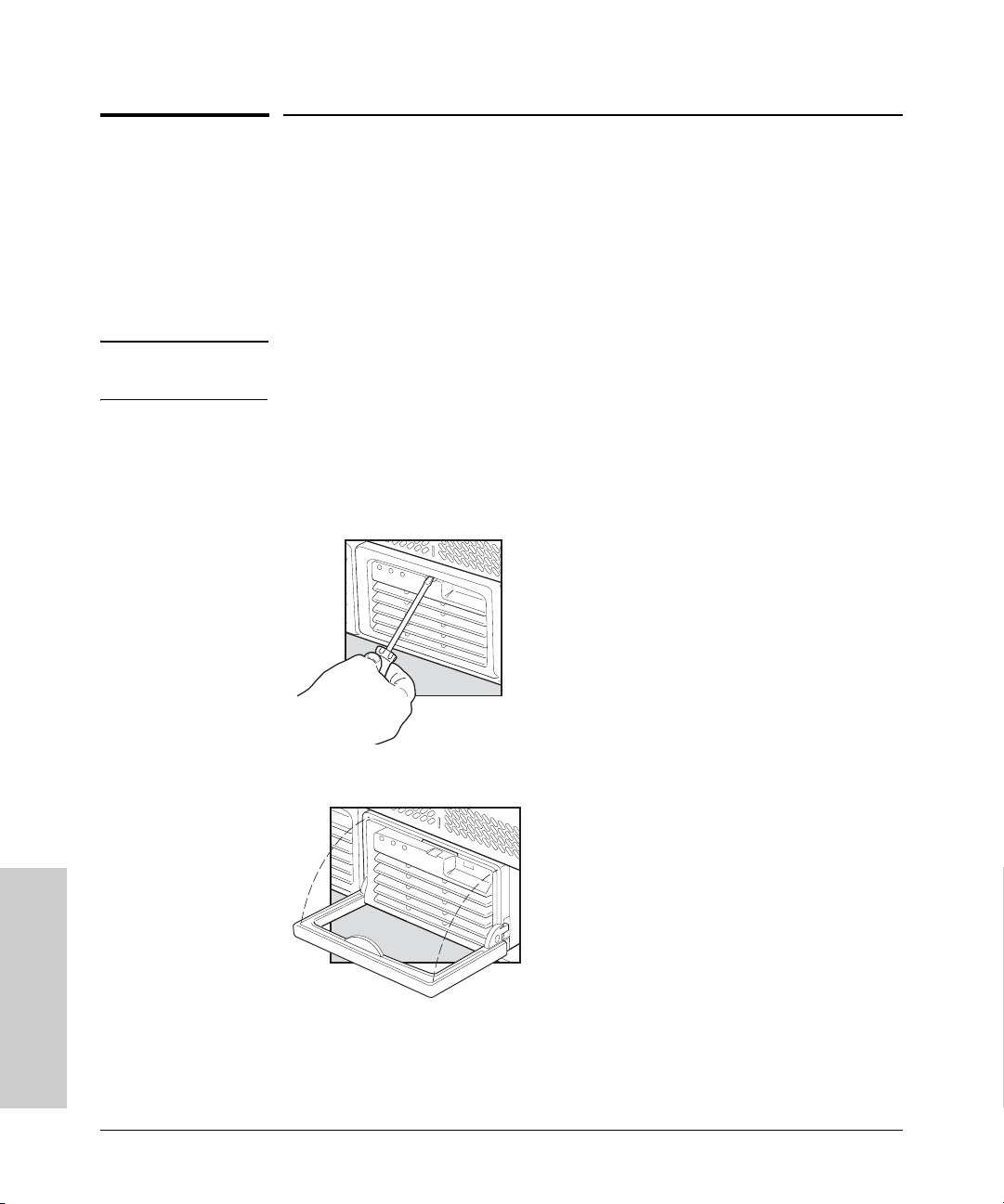
Replacing Hardware
Replacing Power Supplies
Replacing Power Supplies
If your ProCurve 8100fl Switch is configured with redundant power supplies,
you will not suffer any loss of traffic or performance if a power supply fails.
Simply replace the failed component as soon as possible. The Power Status
LED on the chassis and on the power supply unit itself will indicate which
power supply has failed.
Note The Switch 8116fl chassis requires at least two active power supplies
operating to function correctly.
To remove an AC power supply:
1. Ensure that the AC power supply is not plugged into an AC power source.
2. Insert a flat blade screwdriver (or similar lever device) into the indent
located on the bottom edge in the center of the handle
.
Replacing Hardware
4-2
3. Gently turn the screwdriver with the handle downward and lower the
power supply handle to its fully extended position.
4. Pull on the handle to slide the power supply from the chassis.
To install a new or replacement power supply, follow the procedure described
on
page 2-24.
Page 75

Replacing Hardware
Replacing Fan Trays
Replacing Fan Trays
The Fan Status LEDs on the switch chassis and on each fan try indicate when
one or more fans fail. In this case, simply replace the failed component as soon
as possible.
WARNING For safety, if you are hot swapping out the fan tray assembly, pull the assembly
out one-inch and allow the fans to stop rotating before pulling it all the way out.
To replace a fan tray:
1. Remove the two screws holding the failed fan tray assembly. (The LED
on the fan tray and on the chassis will indicate which one is failed.)
2. Pull the fan tray assembly out.
3. Install the new fan tray assembly as described on page 2-15.
Note In case your cabling installation does not allow access to the fan tray
assemblies, remove as many cables as necessary in order to access them.
4-3
Replacing Hardware
Page 76

Replacing Hardware
Replacing Modules
Replacing Modules
The ProCurve Switch 8100fl chassis supports three types of modules:
■ Switch fabric modules
(full-height module for 8116fl; or half-height module for 8108fl)
■ Management modules
■ Interface modules
To replace a module, you must follow a different procedure for different
module types:
■ For a fabric or interface module, you can remove the module from its slot
in the ProCurve 8100fl Switch chassis and install a new module in the
empty slot while the switch is powered on.
■ For a management module, you must first stop the module by entering the
halt command. Then remove the module from its slot and install a new
module.
Caution To avoid damaging modules and the backplane, be sure you are inserting the
right type of module into the slot type made for it.
Replacing Hardware
Hot Swapping and Redundancy
All modules can be “hot swapped”; that is, they can be removed or installed
while the switch is powered on. However, note the following differences
between module types with respect to redundancy:
■ When the primary switch fabric module fails, the redundant switch fabric
module takes over (in less than five seconds) and continues to function
as the primary module even after the failed module is replaced.
■ When hot swapping interface and switch fabric modules, use the CLI
redundancy switchover fabric-module lock command to prevent a redundant
switch fabric module from taking over as the primary switch fabric
module. Once the hot swap is completed, re-enable fabric protection
switching by using the redundancy switchover fabric-module clear command
■ When the primary management module fails, the redundant management
module takes over immediately as the new primary management module.
However, this new primary management module will reboot the other
modules resulting in a loss of traffic until all modules are back on line.
When the failed management module is replaced, the replacement
management module serves as the redundant management module.
4-4
Page 77

Replacing Hardware
Replacing Modules
■ Interface modules do not have redundant protection. If an interface
module fails, traffic on the module will stop until you can replace the
module.
Fail Over Protection
If the primary management module fails, the redundant management module
will reboot the switch fabric module and interface modules. During this time,
service is affected.
To perform a controlled shutdown on a management or fabric module and
cause the redundant module to take over, enter the following command:
Switch 8100fl(config)#halt <slot>
You can also perform a controlled shutdown on a module, by entering the
following command:
Switch 8100fl(config)#power down <slot>
Note To display a list of the slot numbers of all installed modules, type ? after the
command; for example, halt
? or power down ?.
4-5
Replacing Hardware
Page 78

Replacing Hardware
Replacing Modules
Configuration Changes
In normal operation, whenever changes are made to the primary management
module’s configuration file, the changes are copied to the redundant manage
ment module’s configuration file. In this way, if the primary management
module fails, the redundant module has all the configuration information
necessary to take over as the primary.
Removal and Installation Precautions
■ Static electricity can severely damage the electronic components on the modules. When
handling and installing the modules in your switch, follow these procedures to avoid damage
from static electricity:
• Handle the module by its bulkhead or edges and avoid touching the components and the circuitry on the board.
• When installing the module, equalize any static charge difference between your body and the switch by
wearing a grounding wrist strap and attaching it to the switch’s grounding point, or by frequently touching the
switch’s metal body.
• Take appropriate care when removing interface modules from the ProCurve 8100fl Switch. They may be hot to
the touch.
■ The ProCurve 8100fl Switch modules have “low-force”, high-performance connectors. High
insertion forces are not necessary to install the modules, and should not be used.
■ Ensure you fully insert the modules. That is, press the module into the slot until the
bulkhead on the module is contacting or is very close to contacting the front face of the switch
chassis. Then rotate the extractors until they are fully closed (vertical).
■ Once the module is fully inserted, make sure you screw in the two retaining screws to secure
the module in place.
■ For safe operation, proper switch cooling, and reduction of electromagnetic emissions, ensure
that a slot cover is installed on any unused module slot. For safety, no more than one slot should
be uncovered at a time when the switch is powered on.
-
Replacing Hardware
Removing Modules
To remove a module:
1. Loosen the captive screws on each end of the module.
2. Unseat the module by pulling on the ejector levers on the top and bottom
of the module.
3. Carefully remove the module from its slot in the chassis.
4-6
Page 79

Replacing Hardware
Replacing Modules
Installing Modules
To install a new or replacement module:
Note For further details, refer to the installation procedures described on page 2-16.
1. Make sure you install the module in the appropriate slot.
• Switch fabric modules can only be installed in the slots labelled FM-A or FM-B.
• Management modules can only be installed in the slots labelled MM-A or MM-B.
• Interface modules can only be installed in slots numbered 1-8 (Switch 8108fl); or in
slots numbered 1-16 (Switch 8116fl).
2. Slide the module all the way into the slot. Press the ejector levers until
they are vertical to seat the module fully in place, ensuring that the pins
on the back of the module are completely connected to the backplane.
Caution Ensure that the backsheet (metal plate) of the interface module and not
the circuit board is between the module guides. Check both the upper and
lower guides.
3. Tighten the captive screws on each side of the module to secure it to the
chassis.
Verifying the Installation
Once a module is installed, the ProCurve 8100fl Switch recognizes and
activates the module. To verify installation, make sure the Status LED on each
module is solid green.
Note The Active LED will not light on a redundant (non-primary) management
module or on a redundant (non-primary) switch fabric module.
Replacing Hardware
4-7
Page 80
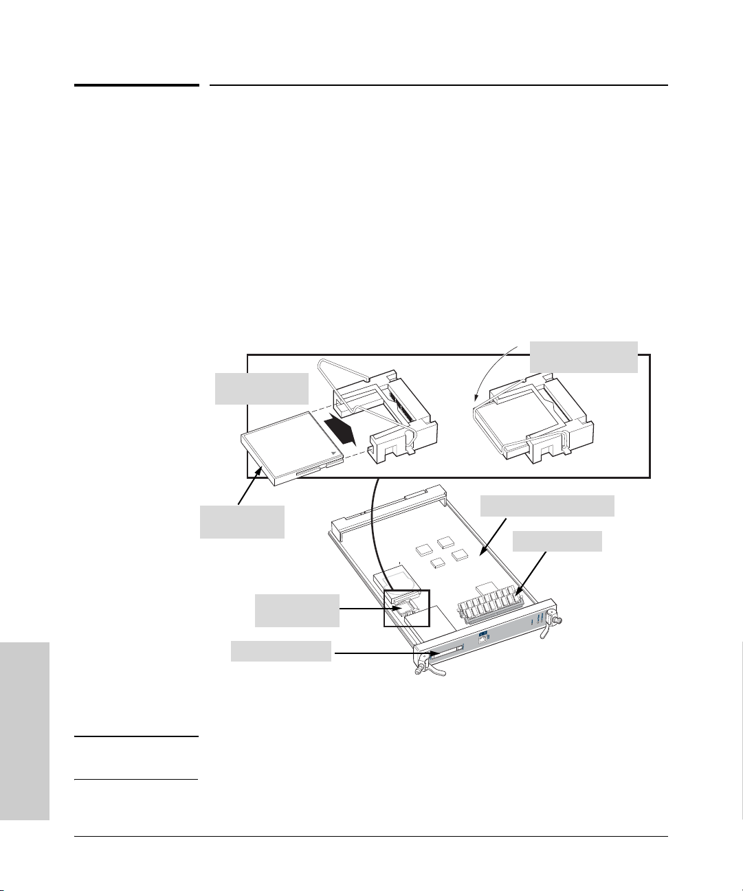
Replacing Hardware
Replacing Compact Flash Card
Replacing Compact Flash Card
The Compact Flash card is the primary non-volatile storage medium located
on the management module that contains both the boot software and
configuration files.
To install (or replace) a Compact Flash card:
1. Remove the management module. (You cannot access the Compact Flash
2. Insert the Compact Flash and snap it into place. (The Compact Flash is
1. Insert Compact
when the management module is installed. This prevents inadvertent
removal of the system image while the system is running.)
keyed so it only goes in one way.) See the following illustration for details.
2. Snap bail over card
to retain in place
Flash card into slot
Replacing Hardware
Compact Flash
Memory card
Compact Flash
Memory card
PCMCIA Card Slot
Management Module
DIMM Slots (2)
3. Reinstall the management module according to the procedures described
in
“Installing a Management Module” on page 2-20.
Note The system software image file normally is stored on the Compact Flash card,
but can also be stored on a TFTP server or BootP server.
4-8
Page 81
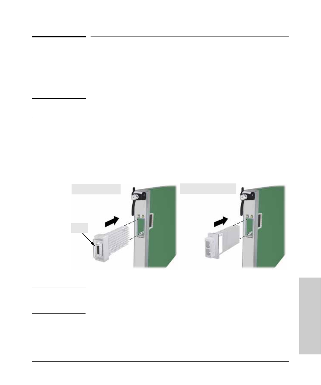
Installing or Removing Transceivers and Connecting Cables
Replacing Hardware
Installing or Removing Transceivers and
Connecting Cables
If you installed a media-flexible X2 10GbE module, you can now install a
copper or fiber optic transceiver to enable network connectivity to a port.
Note You can install or remove a transceiver without having to power off the switch.
Use only the ProCurve supported transceivers (see
Installing Transceivers
To install a transceiver:
1. Remove the port cover on the transceiver slot by squeezing the metal tabs
together.
2. Slide the transceiver into the empty slot until it stops.
page 1-5).
Copper Transceiver
Bail
3. Push firmly until you hear a click and the gasket seat against the bulkhead.
Fiber Optic Transceiver
Note When switch power is on, the Link and Activity LEDs will come on for
approximately two seconds and then go off. This is confirmation the
transceiver is installed.
4. If your transceiver has a bail, move the bail up to lock the transceiver in
place, if not your transceiver is now completely installed. Network cables
can now be installed, see page 4-11.
Replacing Hardware
4-9
Page 82
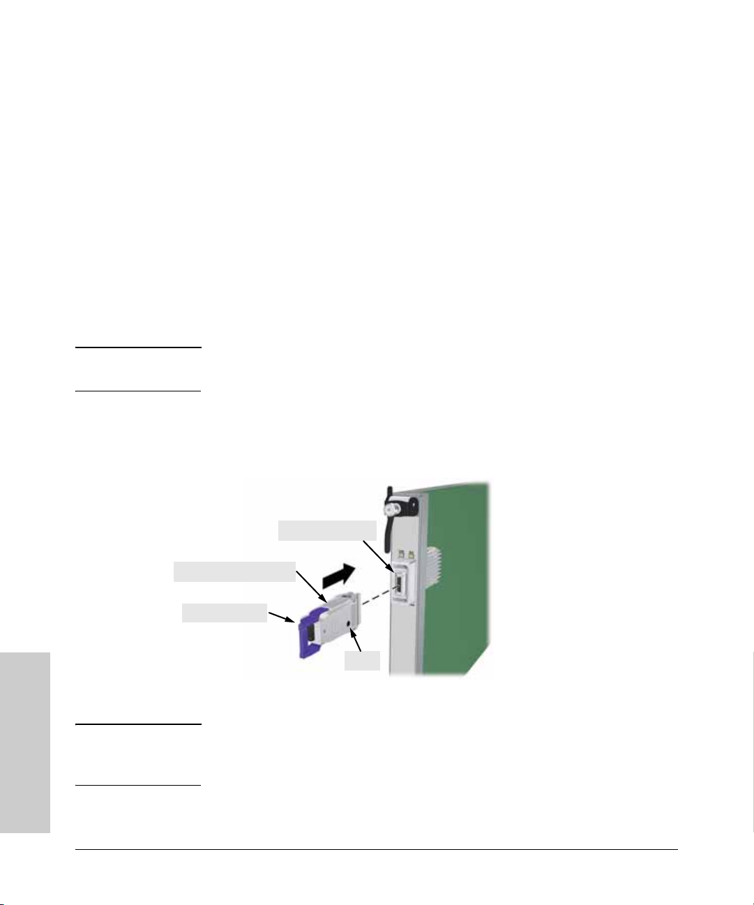
Replacing Hardware
Installing or Removing Transceivers and Connecting Cables
Removing Transceivers
To remove a transceiver:
1. Disconnect the network cable from the transceiver before removing it
from the module.
2. If your transceiver has a wire bail, lower the bail and then use the bail to
pull the transceiver from the slot.
If your transceiver does not have a bail, pull the transceiver straight out.
(Optional) Installing an Optical Media Converter
An optical media converter (OMC) can be installed into the copper transceiver
to enable a fiber-optic cable connection.
Note You can install a media converter without having to power off the switch. Use
only the ProCurve supported media converter (see
To install a media converter:
1. Connect the media converter to the copper transceiver port until it clicks
into place.
page 1-5).
Replacing Hardware
Copper Transceiver
Optical Media Converter
Extractor Handle
LED
2. A multimode fiber ribbon cable can now be installed, see page 4-11.
Note on LED The OMC has a single bi-color LED to indicate Power and Link. The LED
goes Orange when it has power but no link, and goes Green when a link
is established with the other end of a 12-strand flat MTP cable.
4-10
Page 83
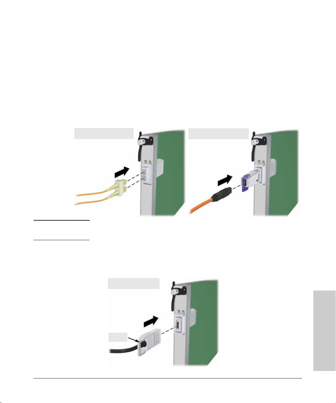
Installing or Removing Transceivers and Connecting Cables
Replacing Hardware
To remove a media converter:
1. Disconnect the network cable from the converter before removing it
from the module.
2. Pull the extractor handle to remove the converter from the transceiver.
Connecting Network Cables to Transceiver Ports
To install fiber-optic cable:
■ Aligning the cable connectors with the slots of the transceiver ports, press
the cable connector into the transceiver port until it snaps into place.
Fiber Optic Transceiver
Optical Media Converter
Note To ensure proper transmit/receive connections, make sure the transmit
from one device is connected to the receive of the other device.
To install copper cable:
1. Insert the copper cable connector into the copper transceiver port.
2. Push the handle forward to engage the locking mechanism.
Copper Transceiver
Replacing Hardware
Handle
4-11
Page 84

Replacing Hardware
Replacing Mini-GBICs
Replacing Mini-GBICs
You can remove or install a mini-GBIC from the 10-port mini-GBIC Module
without having to power off the switch. Use only ProCurve mini-GBICs. The
following mini-GBICs are supported by the ProCurve 8100fl mini-GBIC
module (as of this printing):
■ Gigabit-SX LC mini-GBIC (J4858B)
■ Gigabit-LX LC mini-GBIC (J4859B)
■ Gigabit-LH LC mini-GBIC (J4860B)
■ Gigabit 1000Base-T mini-GBIC (J8177B)
Caution Use only the supported genuine ProCurve mini-GBICs with your switch.
Non-ProCurve mini-GBICs are not supported. Should you require additional
ProCurve mini-GBICs, contact your ProCurve Networking Sales and Service
Office or authorized dealer.
Removing Mini-GBICs
Replacing Hardware
WARNING The ProCurve fiber optic mini-GBICs are Class 1 laser devices. Avoid
direct eye exposure to the beam coming from the transmit port.
The extraction process varies among different mini-GBICs (see the
illustrations and examples in this section). The mini-GBIC removal process is
essentially to disengage the unit from its port via the extraction mechanism,
then pull the unit straight out of the receptacle.
Note You should disconnect the network cable from the mini-GBIC before
removing it from the module.
Depending on when you purchased your ProCurve mini-GBIC, it may have
one of three different release mechanisms: a plastic tab on the bottom, a wire
bail, or a plastic collar around the mini-GBIC (see the following pages for
details).
4-12
Page 85
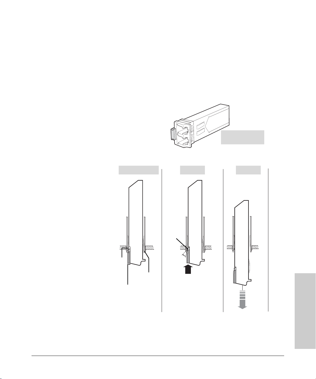
Replacing Hardware
Replacing Mini-GBICs
To remove the a mini-GBIC with a plastic tab or plastic collar:
1. Remove the fiber cable from the mini-GBIC.
2. Push in the plastic tab or collar toward the switch until you see the miniGBIC release from the switch (you can see it move outward slightly)
3. Pull the mini-GBIC from the slot.
4. If the device is not defective (disposable), insert a dust plug to protect it.
mini-GBIC with
plastic tab or collar
Locking tab
Release tab
Installed Position
ProCurve mini-GBIC
Socket
Release Remove
Locking tab
releases
from socket
1. Pull release tab in to
unlatch
ProCurve mini-GBIC
ProCurve mini-GBIC
Replacing Hardware
2. Remove
from
socket
4-13
Page 86
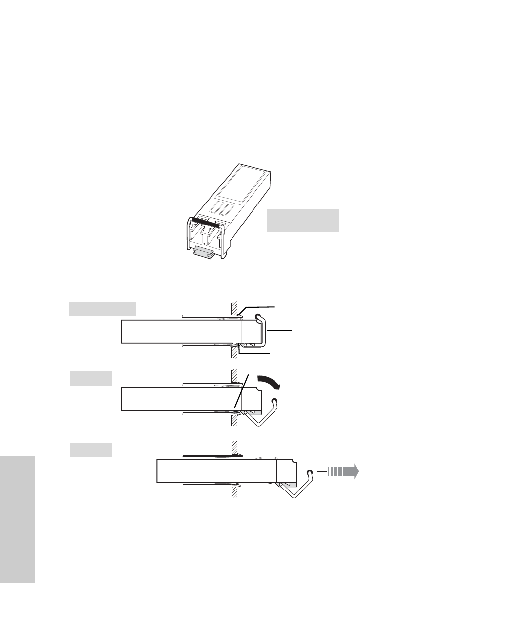
Replacing Hardware
Replacing Mini-GBICs
To remove a mini-GBIC with a wire bail:
1. Remove the fiber cable from the mini-GBIC.
2. Lower the bail until it is approximately horizontal.
3. Using the bail, pull the mini-GBIC from the slot.
4. If the mini-GBIC is not defective (disposable), protect it by inserting a dust
plug.
mini-GBIC with
wire bail release
Replacing Hardware
Installed Position
Release
Remove
ProCurve mini-GBIC
ProCurve mini-GBIC
ProCurve mini-GBIC
Socket
Bail
Locking tab
Locking tab releases from socket
1. Pull bail out
to unlatch
2. Remove from socket
4-14
Page 87
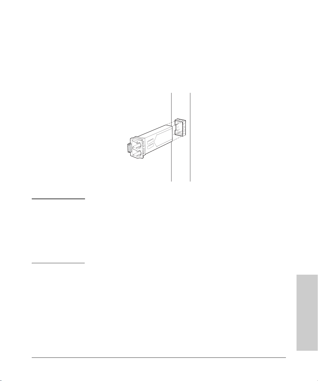
Replacing Hardware
Replacing Mini-GBICs
Installing mini-GBICs
The ProCurve mini-GBICs use slightly different release mechanisms, but the
insertion process is virtually the same for all.
To install a mini-GBIC in the 10-Port mini-GBIC Module:
1. Orient the mini-GBIC as shown in the illustration below. Note that the
release mechanism is on the left of the receptacle.
2. Insert the mini-GBIC into the receptacle until it locks into position.
Caution If the mini-GBIC does not go in easily, do not force it. If the mini-GBIC is
not oriented properly, it will stop about one quarter of the way into the
slot—remove and reorient the mini-GBIC so that it slides easily into the
slot.
Keep the dust plug in the mini-GBIC when there is no fiber cable plugged
in. The optics will not work properly when obstructed with dust or
contaminants. It is recommended that you clean the optic surfaces of the
fiber cable prior to plugging it into the optical bores of the mini-GBIC.
Replacing Hardware
4-15
Page 88

— This page is intentionally unused. —
Page 89

5
Troubleshooting
This chapter describes how to troubleshoot your ProCurve 8100fl switches.
Note that this document describes troubleshooting mostly from a hardware
perspective. You can perform more in-depth troubleshooting using the soft
ware tools available with the switch. For more information, see the chapter
on “Troubleshooting” in the Management and Configuration Guide that is
on the documentation CD-ROM included with your switch.
This chapter describes the following:
■ Basic troubleshooting tips (page 5-1)
■ Diagnosing with the LEDs (page 5-3)
■ Hardware diagnostic tests (page 5-6)
■ Restoring the factory default configuration (page 5-8)
■ Downloading new code (page 5-9)
■ ProCurve Networking customer support services (page 5-9)
Basic Troubleshooting Tips
Most problems are caused by the following situations. Check for these items
first when starting your troubleshooting:
Troubleshooting
-
■ Faulty or loose cables. Look for loose or obviously faulty connections.
If they appear to be OK, make sure the connections are snug. If that does
not correct the problem, try a different cable.
■ Non-standard cables. Non-standard and miswired cables may cause
network collisions and other network problems, and can seriously impair
network performance. Use a new correctly-wired cable or compare your
cable to the cable in appendix B, “Switch Ports and Network Cables” for
pinouts and correct cable wiring. A category 5 cable tester is a recom
mended tool for every 100Base-T and 1000Base-T network installation.
■ Invalid Network Topologies. It is important to make sure you have a
valid network topology. Common topology faults include excessive cable
length and excessive repeater delays between end nodes. If you have
network problems after recent changes to the network, change back to
the previous topology. If you no longer experience the problems, the new
topology is probably at fault.
-
5-1
Page 90

Troubleshooting
Troubleshooting
Basic Troubleshooting Tips
In addition, you should make sure that your network topology contains
no data path loops. Between any two end nodes, there should be only
one active cabling path at any time. Data path loops will cause broadcast
storms that will severely impact your network performance.
With your ProCurve 8100fl switches, if you wish to build redundant paths
between important nodes in your network to provide some fault toler
ance, you should enable Spanning Tree Protocol support on the switch.
This ensures that only one of the redundant paths is active at any time,
thus avoiding data path loops.
ProCurve 8100fl switches also support Link Aggregation, which allows
multiple network cables to be used for a single network connection
without causing a data path loop.
For more information on enabling Spanning Tree and Link Aggregation,
see the Management and Configuration Guide on the documentation
CD-ROM that came with your switch.
■ Check the port configuration. A port on your ProCurve Switch 8100fl
may not be operating as you expect because it has been put into a
“blocking” state by Spanning Tree, or LACP (automatic link aggregation).
(Note that the normal operation of the Spanning Tree and LACP features
may put the port in a blocking state.) Or, the port just may have been
configured as disabled through software.
5-2
Check the port’s configuration and verify that there is not an improper or
undesired configuration of any of the switch features that may be affecting
the port. See the Management and Configuration Guide that is on the
documentation CD-ROM that came with your switch for more informa
-
tion.
For more information on possible network problems and their solutions, refer
to the technical note “Troubleshooting LAN Performance and Intermittent
Connectivity Problems”, which can be found on the ProCurve Networking
Web site,
www.procurve.com, in the Information Library section.
Page 91

Troubleshooting Procedures
Troubleshooting
Troubleshooting Procedures
Table 5-1 describes the error conditions and LED patterns that may occur on
a switch and switch modules.
To troubleshoot Switch 8100fl operation using LEDs:
1. Find the LED pattern in Table 5-1 that you see on your switch.
2. Follow the associated diagnostic procedure to resolve the problem.
Table 5-1. LED Error Conditions
Problem Solution
The power supply is
installed but not working
(no LEDs are on, the fan
module is not operating,
and so on).
1. Verify that the power cable is plugged into an active
power source and to the switch. Ensure these connections are snug.
2. If the Power LED is still not on, verify that the AC power
source works by plugging another device into the outlet.
Or try plugging the switch into a different outlet or try a
different power cable.
If the power source and power cable are OK and this
condition persists, the switch power supply may have failed.
Call your ProCurve Networking-authorized LAN dealer, or
use the electronic support services from ProCurve
Networking to get assistance. See the Customer Support/
Warranty card for more information.
Troubleshooting
The fan module is not
active.
The management module
is not active.
No interface modules are
active.
A specific interface
module is inactive.
Check the power cable and the circuit to which the power
supply is connected.
If the green status LED on the power supply indicates that it
is active, immediately power down the chassis, unplug the
power supply, and contact technical support. The fan
module may be improperly connected or damaged.
Check the power cable and the circuit to which the power
supply is connected.
If the power supply is working, make sure the management
module is inserted all the way into its slot in the chassis and
the captive screws are screwed in. The management module
must be in the management module slot (labelled MM) and
not in a numbered interface module slot.
Check the power cable and the circuit to which the power
supply is connected.
Make sure that the interface module is inserted all the way
into its slot in the chassis, the extractor levers are fully
closed, and the captive screws are screwed in.
5-3
Page 92
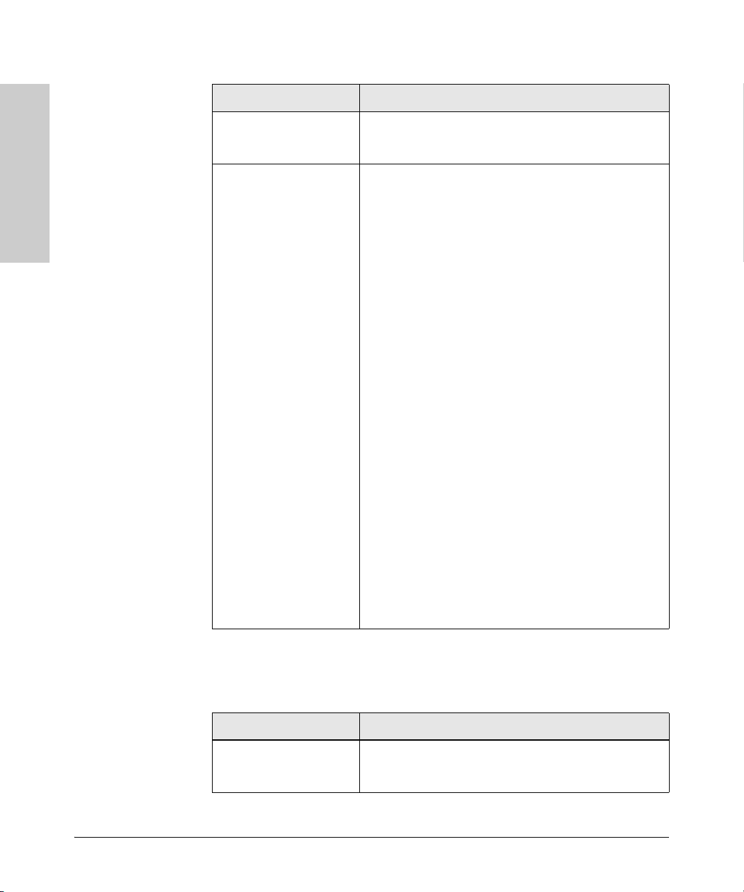
Troubleshooting
Troubleshooting Procedures
Problem Solution
Troubleshooting
The chassis LEDs indicate
activity but you cannot tell
what the switch is doing.
The LED STATUS light on
the interface module is
ORANGE.
Make sure you have properly connected the primary
management module to a management console and the
console is powered on.
When the Status LED on the module is lit, this indicates that
the module received power from the switch, but the
subsequent boot process failed. Either the module is faulty,
or it is a new module type that is not yet supported by the
operating code on the switch.
As ProCurve Networking introduces new modules for your
ProCurve Switch 8100fl, you may have to update the switch
with new operating code that supports the new module. The
documentation that came with the module will indicate
which version of the operating code is needed to support the
module. The modules that are supported in your Switch
8100fl, as of the printing of this manual, are listed in
“ProCurve Switch 8100fl Features” on page 1-14. You can
download the latest code from the Software Updates link on
the ProCurve Networking web site at
First verify the switch has a version of code that supports the
module that is indicating the fault. If the module is not one of
the ones listed on
documentation to see what version of switch code is
needed. Download the new code and retest the module.
If you have the correct code installed in the switch, try
removing and reinstalling the module. You can do this
without having to power down the switch. When the module
is reinstalled, it will be retested automatically.
If the fault indication reoccurs, the module may have failed.
Remove the module from the switch and replace it with
another module, or cover the slot with a blank slot cover. Call
your ProCurve Networking-authorized LAN dealer, or use
the electronic support services from ProCurve Networking
to get assistance. See the Customer Support/Warranty card
for more information.
page 1-14, check the module
www.procurve.com.
5-4
Table 5-2 describes other error conditions and the procedures to follow to
return the switch to normal operation.
Table 5-2. General Error Conditions
Problem Solution
A specific interface
module is inactive.
Make sure that the interface module is inserted all the way
into its slot in the chassis, the extractor levers are fully
closed, and the captive screws are screwed in.
Page 93

Problem Solution
Troubleshooting Procedures
Troubleshooting
An older software version
continues to boot instead
of the newer version on a
PC card or TFTP server.
You have forgotten your
password
You are unable to access
the configuration
commands in the CLI.
Configuration changes do
not seem to be taking
effect.
Configuration changes are
not reinstated after a
reboot.
The Series 8100fl Switch is
not resolving DNS names.
Refer to the Management and Configuration Guide for
procedures on how to configure the Series 8100fl Switch to
boot using newer software.
If you forget your system-level password, you can recover it
by entering boot variables to skip the startup configuration
so that the switch boots up with the factory default settings.
If you forget your UNIX password, it can be reset from
privileged mode by entering the username command to
reconfigure the root password.
In both cases, call your ProCurve Networking-authorized
LAN dealer or use the electronic support services from
ProCurve Networking to get assistance.
Enter the enable command to access the Privileged Exec
mode, then enter the configure command to access the
Configuration mode.
Use the procedure in “Saving and Using the New
Configuration” on page 3-4 to activate the changes.
Use the procedure in “Saving and Using the New
Configuration” on page 3-4 to save the configuration
changes to the Startup configuration file.
Use the procedure in the Management and Configuration
Guide to set up DNS.
If you have already performed this procedure, make sure you
can use NS lookup on the DNS server to get the default
domain.
Troubleshooting
An SNMP manager cannot
access the Series 8100fl
Switch.
You are unable to ping a
certain host.
Use the procedure in the Management and Configuration
Guide to set up an SNMP community string and specify a
target for SNMP traps.
If you have already performed this procedure, enter the show
snmp community command to check the SNMP settings.
Use the traceroute and ping commands to verify that the
Series 8100fl Switch can reach the SNMP management
station.
Create and add an IP interface for the host. See the
Management and Configuration Guide for information.
5-5
Page 94

Troubleshooting
Troubleshooting
Hardware Diagnostic Tests
Hardware Diagnostic Tests
Resetting the Switch
If you believe that the switch is not operating correctly, you can reset the
switch to test its circuitry and operating code.
To reset a switch, choose one of the following options:
■ Unplug and plug in the power cable (power cycling).
■ Enter the reload command from the command-line interface.
Power cycling the switch and the software reset and the reload option cause
the switch to perform a power-on self-test, which almost always will resolve
any temporary operational problem. Neither of these reset procedures causes
any changes to the switch configuration.
Testing Twisted-Pair Cabling
If you think the cable should work but still isn’t working, it may not be
compatible with the IEEE 802.3 Type 10Base-T, 100Base-T, or 1000Base-T
standards, as appropriate for the switch port type that the cable is connected
to. The twisted-pair cables attached to a ProCurve Switch 8100fl must be
compatible with these standards.To verify your cable is compatible with these
standards, use a qualified cable testing device.
5-6
Page 95

Hardware Diagnostic Tests
Troubleshooting
Testing Switch-to-Device Network Communications
You can perform the following communication tests to verify the network is
operating correctly between the switch and any connected device that can
respond correctly to the communication test.
■ Link Test -- a physical layer test that sends IEEE 802.2 test packets to any
device identified by its MAC address
■ Ping Test -- a network layer test used on IP networks that sends test
packets to any device identified by its IP address
These tests can be performed through the switch console interface from a
terminal connected to the switch or through a telnet connection. See the
Management and Configuration Guide that is on the documentation
CD-ROM that came with your switch for more information.
These tests can also be performed from an SNMP network management
station running a program that can manage the switch, for example, ProCurve
Manager or ProCurve Manager Plus.
Testing End-to-End Network Communications
Both the switch and the cabling can be tested by running an end-to-end
communications test -- a test that sends known data from one network device
to another through the switch. For example, if you have two PCs on the
network that have LAN adapters between which you can run a link-level test
or Ping test through the switch, you can use this test to verify the entire
communication path between the two PCs is functioning correctly. See your
LAN adapter documentation for more information on running a link test or
Ping test.
Troubleshooting
5-7
Page 96

Troubleshooting
Troubleshooting
Restoring the Factory Default Configuration
Restoring the Factory Default
Configuration
As part of your troubleshooting process, it may become necessary to return
the switch configuration to the factory default settings. This process inter
rupts the switch operation, clears any passwords, clears the console event log,
resets the network counters to zero, performs a complete self test, and reboots
the switch into its factory default configuration including deleting an IP
address, if one is configured.
Note This process removes all switch configuration changes that you have made
from the factory default settings. This includes, for example, configuration of
VLANs, spanning tree, trunks, routing, and security. Returning the configura
tion of these features to their factory default settings (usually disabling them)
may result in network connectivity issues.
If the switch has a valid configuration, and you are restoring the factory default
settings for a reason other than configuration problems, you should save the
switch configuration prior to performing the factory default reset. Then, after
the reset and resolution of the original problem, you can restore the saved
configuration to the switch. For both the save and restore processes, you can
use the console copy command. See the switch Management and Configura
tion Guide that is on the documentation CD-ROM for more information on
this command.
-
-
-
5-8
You can restore the factory default configuration by using the switch console.
To restore the factory default configuration from the console:
■ Enter the following command at the console prompt to back up the startup
configuration:
Switch 8100fl#copy startup flash:startup.bak
■ Enter the following command to erase the setup configuration:
Switch 8100fl#erase startup
■ You can also restore the factory default configuration by entering the
following commands from the boot prompt:
PMON> set STARTUP_MODE skip_config
PMON> reset
Page 97
ProCurve Networking Customer Support
Troubleshooting
ProCurve Networking Customer
Support
If you are still having trouble with your switch, ProCurve Networking offers
support 24 hours a day, seven days a week through the use of a number of
automated electronic services. See the Customer Support/Warranty booklet
that came with your switch for information on how to use these services to
get technical support. The ProCurve Networking Web site,
www.procurve.com also provides up-to-date support information.
Additionally, your ProCurve Networking-authorized network reseller can
provide you with assistance, both with services that they offer and with
services offered by ProCurve Networking.
Before Calling Support
Before calling your networking dealer or ProCurve Networking technical
support, to make the support process most efficient, first retrieve the
following information:
Information Item Information Location
• Product identification, including the chassis,
modules, and mini-GBICs
On the front of the switch and on
modules and mini-GBICs
Troubleshooting
• Details about the switch’s status including the OS
(software) version, a copy of the switch configuration, a copy of the switch Event Log, and a copy of
the switch status and counters information
• Copy of your network topology map, including network addresses assigned to the relevant devices
Switch console:
show tech-support command
Your network records
5-9
Page 98

Troubleshooting
Troubleshooting
Downloading New Code
Downloading New Code
When product enhancements occur for the ProCurve Switch 8100fl Series,
new code can be downloaded to the switch through several methods, for
product enhancements and new features. Please see the Management and
Configuration Guide that is on the documentation CD-ROM that came with
your switch for more information.
New code is available on the ProCurve Networking web site at
www.procurve.com.
5-10
Page 99

Specifications
Switch 8108fl
Physical
A
Width:
Depth:
Height:
Weight:
• Minimum (empty chassis without slot covers)
• Maximum (fully loaded with maximum
number of modules, power supplies, fan trays)
• Empty chassis with covers and blanks
(weight as shipped)
• By component:
– Fan Tray (each)
– Power Supply (each)
– Blank Power Supply
– Management Module
– Switch Fabric Module (8108fl)
– 1-Port 10-GbE LR Interface Module
– 10-Port 100/1000-T Interface Module
– 10-Port mini-GBIC Interface Module
– 1-Port X2 10-GbE Interface Module
– 2-Port X2 10-GbE Interface Module
– Interface Module Slot Cover
– Management Module Slot Cover
– Switch Fabric Module (8008fl) Slot Cover
– Mounting Bracket (each)
43.9 cm (17.3 in)
54.6 cm (21.5 in)
57.7 cm (22.7 in)
42.5 kg (93.8 lbs)
99.7 kg (219.7 lbs)
60.1 kg (132.5 lbs)
4.7 kg (10.4 lbs)
3.3 kg (7.3 lbs)
1.3 kg (2.8 lbs)
2.9 kg (6.4 lbs)
3.1 kg (6.8 lbs)
3.4 kg (7.4 lbs)
3.0 kg (6.7 lbs)
3.1 kg (6.8 lbs)
3.4 kg (7.4 lbs)
3.4 kg (7.4 lbs)
1.5 kg (3.3 lbs)
1.5 kg (3.3 lbs)
1.5 kg (3.3 lbs)
0.9 kg (2.0 lbs)
Specifications
A-1
Page 100

Specifications
Switch 8108fl
Electrical
AC power (per power supply): 100–240 VAC
• Maximum current 15 A
• Frequency Range 47–63 Hz
AC power (maximum system) 1440 W
Maximum input current 15 A @ 100 VAC
12 A @ 120 VAC
10 A @ 150 VAC
8 A @ 208 VAC
Environmental
Operating Non-Operating
Temperature: 5°C to 40°C (41°F to 104°F) -40°C to 70°C (-40°F to 158°F)
Specifications
Relative humidity: 15% to 80% (@ 40°C, 24 hours) 90% (@ 65°C, 12hours)
(non-condensing)
Maximum altitude: 3.0 Km (10,000 ft) 4.6 Km (15,000 ft)
Acoustic
• Acoustic sound pressure LpAm = 63.6dB
• Acoustic sound power LWAd = 80dB per ISO 7779
Safety and Regulatory
• FCC Rules Part 15, subpart B (Class A)
• ICE-003, Canadian Radio Interference Regulations (Class A)
• EN 55022/CISPR 22 (Class A)
• EN55024
• EN 61000-3-2 (Harmonics)
• EN 61000-3-3 (Flicker)
• UL60950-1/UL1950 3rd
• CSA C22.2 No 60950-1
• EN60950-1/ IEC60950 3rd
• EN60825
A-2
 Loading...