

Page 1

4080~1.boo : 4080_0.FM Page i Thursday, July 2, 1998 1:43 PM
HP ProCurve
Switch 4000M and 8000M
Installation Guide
Page 2

4080~1.boo : 4080_0.FM Page ii Thursday, July 2, 1998 1:43 PM
© Copyright 1998 Hewlett-Packard Company
All Rights Reserved.
This document contains information which is protected by
copyright. Reproduction, adaptation, or translation without
prior permission is prohibited, except as allowed under the
copyright laws.
Publication Number
5967-6916
June 1998
Applicable Products
HP ProCurve Switch 4000M (HP J4121A)
HP ProCurve Switch 8000M (HP J4110A)
Disclaimer
The information contained in this document is subject to
change without notice.
HEWLETT-PACKARD COMPANY MAKES NO WARRANTY
OF ANY KIND WITH REGARD TO THIS MATERIAL,
INCLUDING, BUT NOT LIMITED TO, THE IMPLIED
WARRANTIES OF MERCHANTABILITY AND FITNESS
FOR A PARTICULAR PURPOSE. Hewlett-Packard shall not
be liable for errors contained herein or for incidental or
consequential damages in connection with the furnishing,
performance, or use of this material.
Hewlett-Packard assumes no responsibility for the use or
reliability of its software on equipment that is not furnished
by Hewlett-Packard.
Warranty
See the Customer Support/Warranty booklet included with
the product.
A copy of the specific warranty terms applicable to your
Hewlett-Packard products and replacement parts can be
obtained from your HP Sales and Service Office or
authorized dealer.
Hewlett-Packard Company
8000 Foothills Boulevard, m/s 5552
Roseville, California 95747-5552
http://www.hp.com/go/network_city
Page 3

4080~1.boo : 4080TOC.FM Page iii Thursday, July 2, 1998 1:43 PM
Contents
1 Introducing the HP ProCurve Switch 4000M and 8000M
Front of the Switch
LEDs . . . . . . . . . . . . . . . . . . . . . . . . . . . . . . . . . . . . . . . . . . . . . . . . . . . . . . 1-4
Mode Select Button and Indicator LEDs . . . . . . . . . . . . . . . . . . . . . . . . 1-6
Console Port . . . . . . . . . . . . . . . . . . . . . . . . . . . . . . . . . . . . . . . . . . . . . . . 1-6
Reset Button . . . . . . . . . . . . . . . . . . . . . . . . . . . . . . . . . . . . . . . . . . . . . . . 1-7
Clear Button . . . . . . . . . . . . . . . . . . . . . . . . . . . . . . . . . . . . . . . . . . . . . . . . 1-7
Back of the Switch
Power Connector . . . . . . . . . . . . . . . . . . . . . . . . . . . . . . . . . . . . . . . . . . . 1-8
Slot for Redundant Power Supply . . . . . . . . . . . . . . . . . . . . . . . . . . . . . . 1-8
Switch Features
Switch Operation Overview
Address Table Operation . . . . . . . . . . . . . . . . . . . . . . . . . . . . . . . . . . . . 1-10
Simultaneous Network Communications . . . . . . . . . . . . . . . . . . . . . . 1-11
Effect of VLANs . . . . . . . . . . . . . . . . . . . . . . . . . . . . . . . . . . . . . . . . . . . . 1-11
. . . . . . . . . . . . . . . . . . . . . . . . . . . . . . . . . . . . . . . . . . . . 1-3
. . . . . . . . . . . . . . . . . . . . . . . . . . . . . . . . . . . . . . . . . . . . 1-8
. . . . . . . . . . . . . . . . . . . . . . . . . . . . . . . . . . . . . . . . . . . . . . . 1-9
. . . . . . . . . . . . . . . . . . . . . . . . . . . . . . . . . . . 1-10
2 Installing the Switch 4000M and 8000M
Included Parts
. . . . . . . . . . . . . . . . . . . . . . . . . . . . . . . . . . . . . . . . . . . . . . . . 2-1
Installation Procedures
Summary . . . . . . . . . . . . . . . . . . . . . . . . . . . . . . . . . . . . . . . . . . . . . . . . . . . 2-2
Installation Precautions . . . . . . . . . . . . . . . . . . . . . . . . . . . . . . . . . . . . . . 2-3
1. Prepare the Installation Site . . . . . . . . . . . . . . . . . . . . . . . . . . . . . . . . 2-4
2.Install Switch Modules . . . . . . . . . . . . . . . . . . . . . . . . . . . . . . . . . . . . . 2-5
3. (Optional) Install Second Power Supply . . . . . . . . . . . . . . . . . . . . . . 2-6
4. Verify the Switch Passes Self Test . . . . . . . . . . . . . . . . . . . . . . . . . . . 2-8
5. Mount the Switch . . . . . . . . . . . . . . . . . . . . . . . . . . . . . . . . . . . . . . . . 2-10
. . . . . . . . . . . . . . . . . . . . . . . . . . . . . . . . . . . . . . . . 2-2
LED Behavior: . . . . . . . . . . . . . . . . . . . . . . . . . . . . . . . . . . . . . . . . . . 2-9
Rack or Cabinet Mounting . . . . . . . . . . . . . . . . . . . . . . . . . . . . . . . 2-10
Horizontal Surface Mounting . . . . . . . . . . . . . . . . . . . . . . . . . . . . . 2-12
Wall Mounting . . . . . . . . . . . . . . . . . . . . . . . . . . . . . . . . . . . . . . . . . . 2-13
iii
Page 4

4080~1.boo : 4080TOC.FM Page iv Thursday, July 2, 1998 1:43 PM
6. Connect the Switch to a Power Source . . . . . . . . . . . . . . . . . . . . . . 2-14
7. Connect the Network Devices . . . . . . . . . . . . . . . . . . . . . . . . . . . . . . 2-14
8. (Optional) Connect a Console to the Switch . . . . . . . . . . . . . . . . . . 2-15
Terminal Configuration . . . . . . . . . . . . . . . . . . . . . . . . . . . . . . . . . . 2-15
Direct Console Access . . . . . . . . . . . . . . . . . . . . . . . . . . . . . . . . . . . 2-16
Telnet Console Access . . . . . . . . . . . . . . . . . . . . . . . . . . . . . . . . . . 2-16
Hot Swapping Switch Modules . . . . . . . . . . . . . . . . . . . . . . . . . . . . . . . . 2-17
Adding or Replacing Modules . . . . . . . . . . . . . . . . . . . . . . . . . . . . . . . . 2-17
Changing the Module Type . . . . . . . . . . . . . . . . . . . . . . . . . . . . . . . . . . 2-17
Where to Go From Here . . . . . . . . . . . . . . . . . . . . . . . . . . . . . . . . . . . . . . 2-18
3 Troubleshooting
Basic Troubleshooting Tips . . . . . . . . . . . . . . . . . . . . . . . . . . . . . . . . . . . . 3-2
Diagnosing with the LEDs . . . . . . . . . . . . . . . . . . . . . . . . . . . . . . . . . . . . . 3-4
Proactive Networking . . . . . . . . . . . . . . . . . . . . . . . . . . . . . . . . . . . . . . . . . 3-7
Hardware Diagnostic Tests . . . . . . . . . . . . . . . . . . . . . . . . . . . . . . . . . . . . 3-8
Testing the Switch by Resetting It . . . . . . . . . . . . . . . . . . . . . . . . . . . . . 3-8
Checking the Switch LEDs . . . . . . . . . . . . . . . . . . . . . . . . . . . . . . . . 3-8
Checking Console Messages . . . . . . . . . . . . . . . . . . . . . . . . . . . . . . . 3-8
Testing Twisted-Pair Cabling . . . . . . . . . . . . . . . . . . . . . . . . . . . . . . . . . . 3-9
Testing Switch-to-Device Network Communications . . . . . . . . . . . . . 3-9
Testing End-to-End Network Communications . . . . . . . . . . . . . . . . . 3-10
Restoring the Factory Default Configuration . . . . . . . . . . . . . . . . . . 3-10
HP Customer Support Services . . . . . . . . . . . . . . . . . . . . . . . . . . . . . . . . 3-11
A Specifications
Physical . . . . . . . . . . . . . . . . . . . . . . . . . . . . . . . . . . . . . . . . . . . . . . . . . . . A-1
Electrical . . . . . . . . . . . . . . . . . . . . . . . . . . . . . . . . . . . . . . . . . . . . . . . . . A-1
Environmental . . . . . . . . . . . . . . . . . . . . . . . . . . . . . . . . . . . . . . . . . . . . . A-1
Acoustic . . . . . . . . . . . . . . . . . . . . . . . . . . . . . . . . . . . . . . . . . . . . . . . . . . A-2
Connectors . . . . . . . . . . . . . . . . . . . . . . . . . . . . . . . . . . . . . . . . . . . . . . . . A-2
Safety . . . . . . . . . . . . . . . . . . . . . . . . . . . . . . . . . . . . . . . . . . . . . . . . . . . . A-2
iv
Page 5

4080~1.boo : 4080TOC.FM Page v Thursday, July 2, 1998 1:43 PM
B Cables and Connectors
Twisted-Pair Cable/Connector Pin-Outs
Twisted-Pair Cable for Switch (MDI-X) to
Computer (MDI) Network Connection . . . . . . . . . . . . . . . . . . . . . . . . B-2
Twisted-Pair Cable for Switch (MDI-X) to
Hub or Switch (MDI-X) Network Connection . . . . . . . . . . . . . . . . . . . B-3
Twisted-Pair Cable Pin Assignments . . . . . . . . . . . . . . . . . . . . . . . . . . B-4
Twisted-Pair Straight-Through Cable . . . . . . . . . . . . . . . . . . . . . . B-4
Twisted-Pair Cross-Over Cable . . . . . . . . . . . . . . . . . . . . . . . . . . . B-4
Fiber-Optic Cables
10Base-FL Ports . . . . . . . . . . . . . . . . . . . . . . . . . . . . . . . . . . . . . . . . . . . . B-5
100Base-FX Ports . . . . . . . . . . . . . . . . . . . . . . . . . . . . . . . . . . . . . . . . . . B-5
Gigabit-SX Ports . . . . . . . . . . . . . . . . . . . . . . . . . . . . . . . . . . . . . . . . . . . B-5
. . . . . . . . . . . . . . . . . . . . . . . . . . . . . . . . . . . . . . . . . . . B-5
. . . . . . . . . . . . . . . . . . . . . . . B-1
C Safety and EMC Regulatory Statements
Safety Information
EMC Regulatory Statements
. . . . . . . . . . . . . . . . . . . . . . . . . . . . . . . . . . . . . . . . . . . C-1
. . . . . . . . . . . . . . . . . . . . . . . . . . . . . . . . . . C-8
v
Page 6

4080~1.boo : 4080TOC.FM Page vi Thursday, July 2, 1998 1:43 PM
Page 7
4080~1.boo : 4080_1.FM Page 1 Thursday, July 2, 1998 1:43 PM
Introducing the HP ProCurve Switch 4000M
and 8000M
The HP ProCurve Switch 4000M and 8000M are multiport switches that can
be used to build high-performance switched workgroup networks. These
switches are store-and-forward devices that offer low latency for high-speed
networking.
1
Introducing the HP ProCurve
Switch 4000M and 8000M
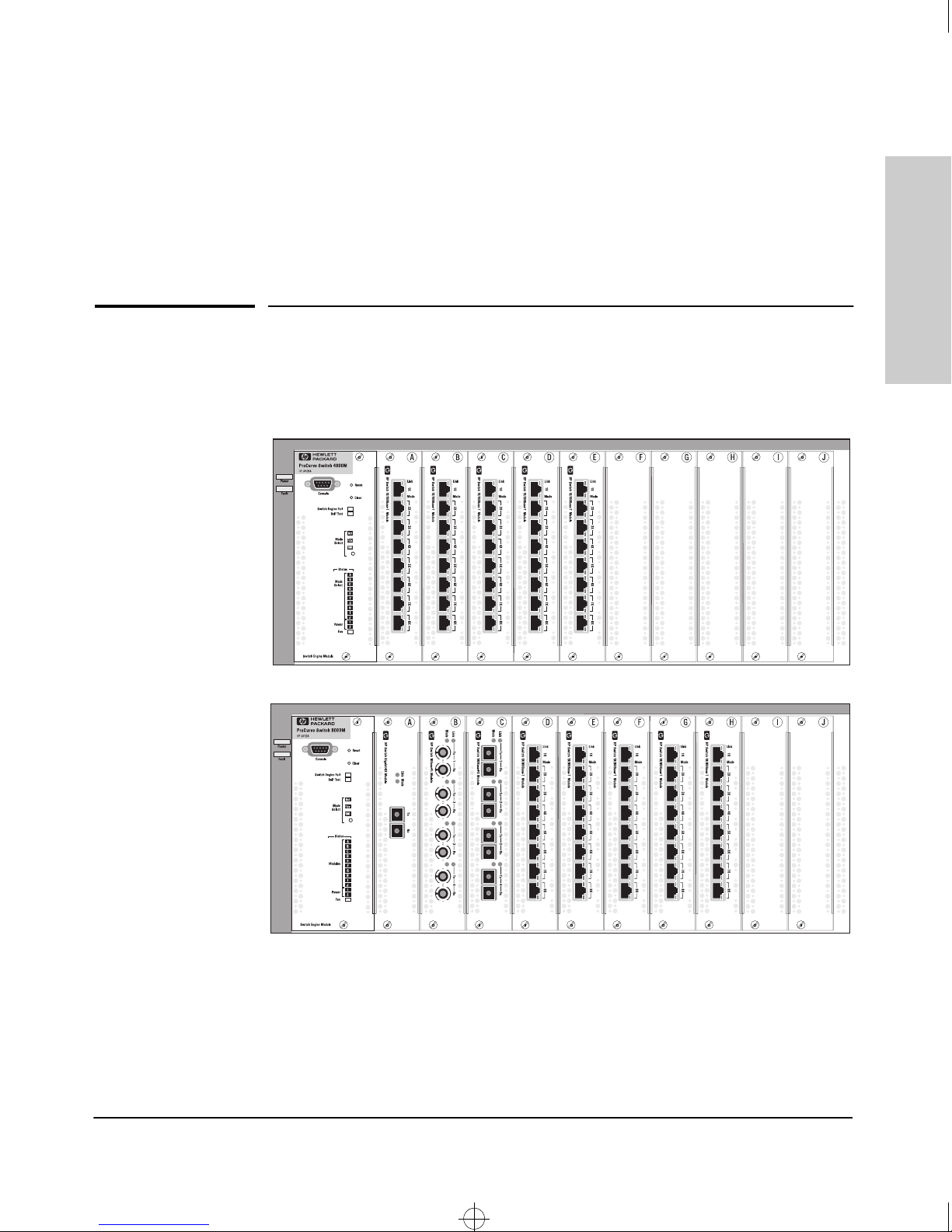
HP ProCurve Switch 4000M
(HP J4121A)
five 10/100Base-T Modules
are preinstalled
HP ProCurve Switch 8000M
(HP J4110A)
showing a sample of switch
modules installed
Throughout this manual, these switches will be abbreviated as the Switch
4000M and Switch 8000M, or when common features are being described, as
the Switch 4000M and 8000M.
1-1
Page 8

4080~1.boo : 4080_1.FM Page 2 Thursday, July 2, 1998 1:43 PM
Introducing the HP ProCurve Switch 4000M and 8000M
The Switch 4000M has five preinstalled HP ProCurve Switch 10/100Base-T
Modules and five universal slots for installing any of the supported switch
modules.
The Switch 8000M has 10 universal slots for installing any of the supported
switch modules.
See “Switch Features” on page 1-9 for a list of the switch modules available
when this manual was printed.
Switch 4000M and 8000M
Introducing the HP ProCurve
With these switches you can build a switched network infrastructure by
connecting it to hubs, other switches, or routers, or you can connect
computers, printers, and servers to this switch to provide dedicated bandwidth to those devices.
This chapter describes your HP Switch 4000M and 8000M including:
■ Front and back of the switch
■ Features
Switch operation overview
■
1-2
Page 9
4080~1.boo : 4080_1.FM Page 3 Thursday, July 2, 1998 1:43 PM
Introducing the HP ProCurve Switch 4000M and 8000M
Front of the Switch
Front of the Switch
Introducing the HP ProCurve
Switch 4000M and 8000M
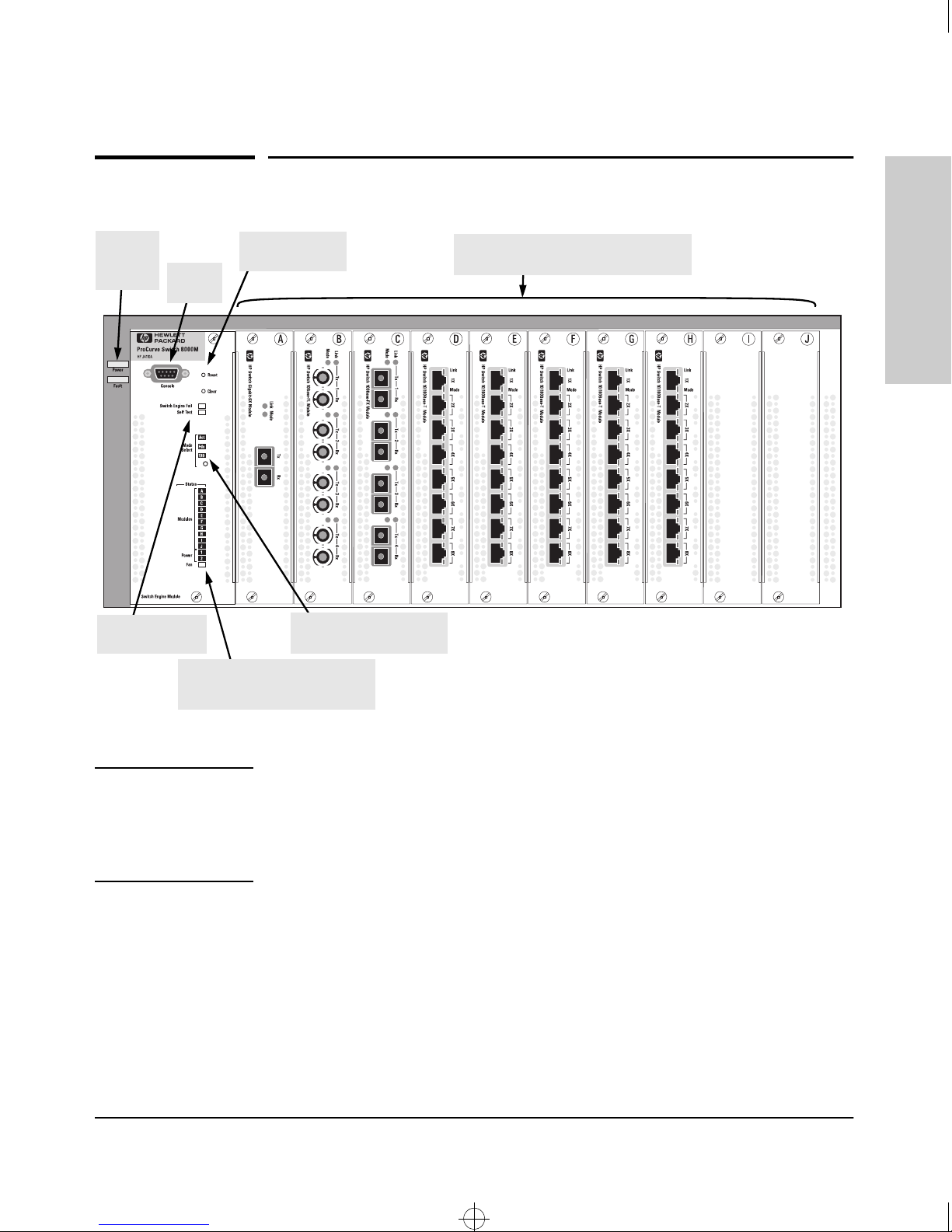
Power
and Fault
LEDs
Engine Fail and
Self Test LEDs
Reset and Clear
buttons
Console
Port
Status LEDs for Switch
Modules, Power Supplies,
and Fans
Switch Modules and slots
with Link and Mode LEDs for each port
Mode Select button
and indicator LEDs
Note
The Switch 8000M is shown in this illustration with a variety of modules
installed.
The Switch 4000M has the same physical features, but with five 10/100Base-T
switch modules preinstalled in slots A through E.
1-3
Page 10
4080~1.boo : 4080_1.FM Page 4 Thursday, July 2, 1998 1:43 PM
Introducing the HP ProCurve Switch 4000M and 8000M
Front of the Switch
LEDs
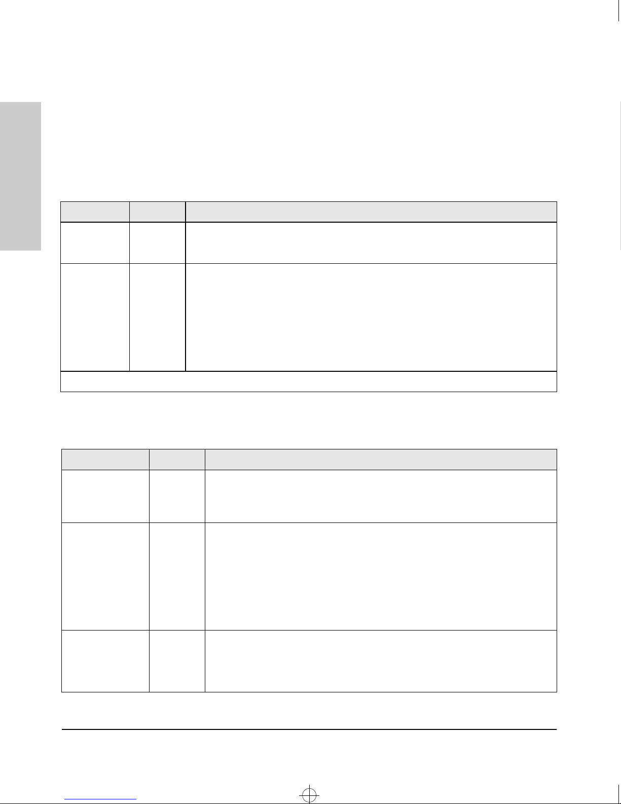
As described in the next three tables, there are LEDs on the switch chassis,
on the Switch Engine Module, and on the switch modules that keep you
informed of the status of the switch and the network connections.
Table 1-1. Switch LEDs
LEDs State Meaning
Switch 4000M and 8000M
Introducing the HP ProCurve
Power
(green)
Fault
(orange)
†
The flashing behavior is an on/off cycle once every 1.6 seconds, approximately.
LED State Meaning
Switch Engine Fail
(orange)
On The switch is receiving power.
Off The switch is NOT receiving power.
Off The normal state; indicates that there are no fault conditions on the switch.
†
Flashing
On On briefly at the beginning of switch self test after the switch is powered on or reset. If
A fault has occurred on the Switch Engine, one of the switch modules, a power supply,
or a fan. The Status LED for the module or other device with the fault will flash
simultaneously.
on for a prolonged time, the switch has encountered a fatal hardware failure, or has failed
its self test. See chapter 3, “Troubleshooting” for more information.
Table 1-2. Switch Engine LEDs
Off The normal state; indicates that there are no fault conditions on the Switch Engine.
On or
Flashing
A fault has occurred on the Switch Engine. The switch Fault LED and the Self Test
†
LED will also be either on or flashing simultaneously, depending on the type of failure.
Self Test
(green)
Mode Select
(3 green LEDs)
Off The normal operational state; the switch is not undergoing self test.
On The switch self test and initialization are in progress after you have power cycled
Flashing
Act Indicates that the port Mode LEDs are displaying network activity information.
Fdx Indicates that the port Mode LEDs are lit for ports that are in Full Duplex Mode.
100 Indicates that the port Mode LEDs are lit for ports that are operating at 100 Mbps.
†
1-4
or reset the switch. The switch is not operational until this LED goes off. The Self
Test LED also comes on briefly when you “hot swap” a module into the switch and
the module is automatically self tested.
A component of the switch has failed its self test. The Status LED for that component,
for example a switch module, and the switch Fault LED will flash simultaneously.
Page 11
4080~1.boo : 4080_1.FM Page 5 Thursday, July 2, 1998 1:43 PM
Introducing the HP ProCurve Switch 4000M and 8000M
Front of the Switch
LED State Meaning
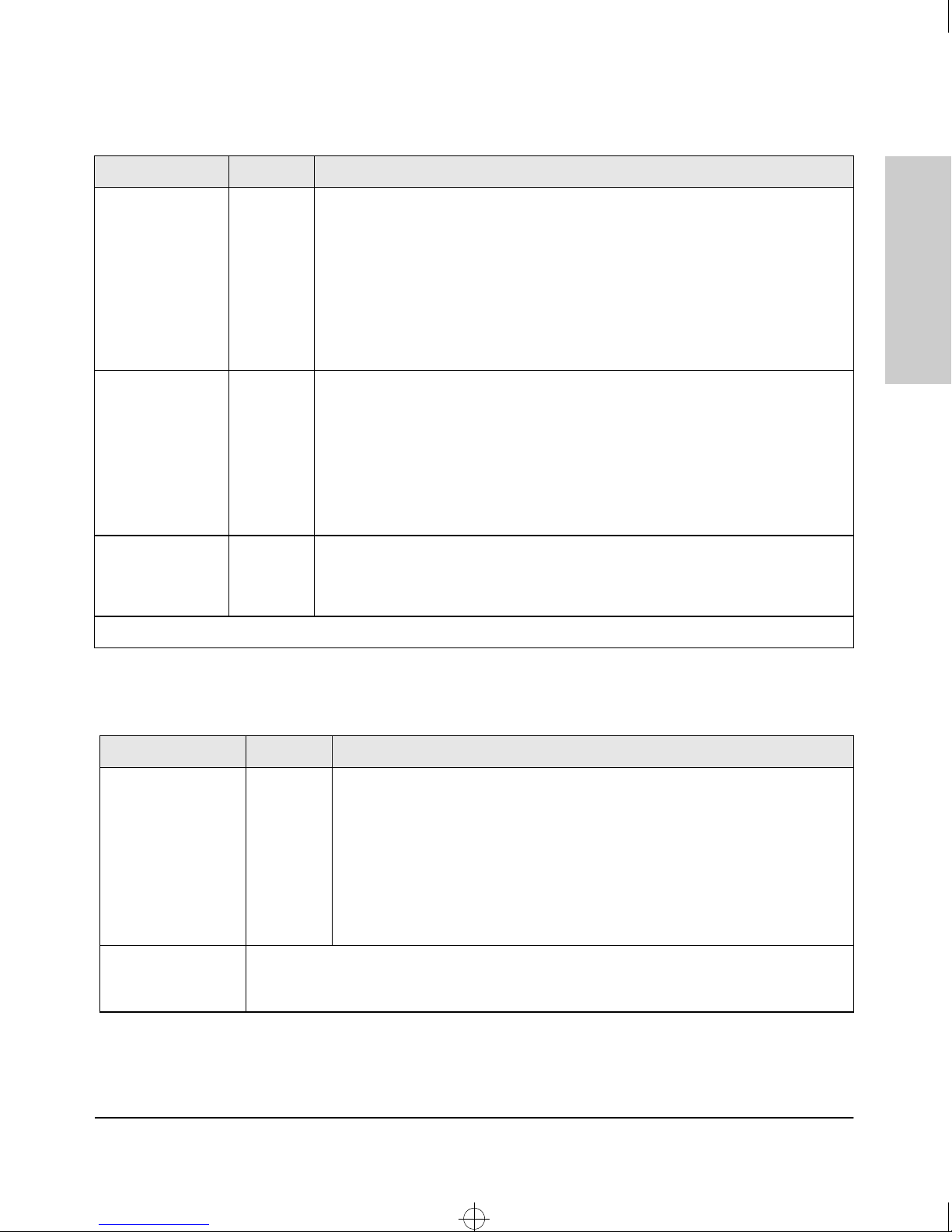
Status/Modules
(green - letters
corresponding to
the switch module
slots)
Status/Power
(green - numbers
corresponding to
the power supply
positions)
Status/Fan
(green)
†
The flashing behavior is an on/off cycle once every 1.6 seconds, approximately.
On A module is installed in the switch module slot corresponding to the letter and the
module is undergoing or has passed self test. This also occurs when you install a
module when the switch is powered on (“hot swap”).
Off A module is not installed in the switch module slot corresponding to the letter.
†
Flashing
On A power supply is installed in the position in the back of the switch corresponding
Off A power supply is not installed in the position corresponding to the number.
Flashing
On The cooling fans are operating normally.
Flashing
The module status LED flashes very briefly when a module is being hot swapped. If
the LED flashes for a prolonged time, the module in the slot corresponding to the
letter has failed self test or encountered some other error condition. See chapter 3,
“Troubleshooting” for a more information.
to the number, and the supply is plugged in to an active AC power source. As shipped,
the switch has a single power supply in position 1.
†
The power supply installed in the position corresponding to the number is not
plugged in to an active AC power source, or has experienced a fault. The switch
Fault LED will be flashing simultaneously.
†
One or more of the cooling fans have failed. The switch Fault LED will be flashing
simultaneously.
Introducing the HP ProCurve
Switch 4000M and 8000M
Table 1-3. Switch Module LEDs
LED State Meaning
Link On Indicates the port is enabled and receiving a link beat signal (for the twisted-pair
ports), or a strong enough light level (for the fiber-optic ports) from the connected
device.
Off One of these conditions exists:
• no active network cable is connected to the port
• the port is not receiving link beat or sufficient light
• the port has been disabled through the switch console, the web browser
interface, or HP TopTools.
Mode Displays network activity information, or whether the port is configured for Full Duplex
operation, or 100 Mbps operation depending on the mode selection. See “Mode Select Button
and Indicator LEDs” below for more information.
1-5
Page 12
4080~1.boo : 4080_1.FM Page 6 Thursday, July 2, 1998 1:43 PM
Introducing the HP ProCurve Switch 4000M and 8000M
Front of the Switch
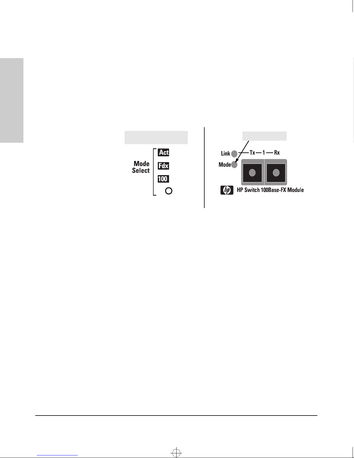
Mode Select Button and Indicator LEDs
To optimize the amount of information that can be displayed for each of the
switch ports without overwhelming you with LEDs, the Switch 4000M and
8000M use a Mode LED for each port. The operation of this LED is controlled
by the Mode Select button on the Switch Engine, and the current setting is
indicated by the Mode Indicator LEDs near the button. Press the button to
step from one mode to the next.
Switch 4000M and 8000M
Introducing the HP ProCurve
Mode Select button and
indicator LEDs
If the Activity (Act) indicator LED is lit, each port Mode LED displays
■
Port Mode LED
activity information for the port—it flickers as network traffic is received
and transmitted through the port.
■ If the Full Duplex (Fdx) indicator LED is lit, the port Mode LEDs light for
those ports that are operating in full duplex.
■ If the 100 Mbps (100) indicator LED is lit, the port Mode LEDs light for
those ports that are operating at 100 Mbps.
Console Port
This port is used to connect a console to the switch by using the serial cable
supplied with the switch. This connection is described under “Connecting a
Console to the Switch” in chapter 2, “Installing the Switch 4000M and 8000M”.
The console is a full-featured interface that you can use to configure, monitor,
and troubleshoot the switch. It can be run on a PC emulating a VT-100 terminal,
or on a standard VT-100 terminal.
1-6
Page 13

4080~1.boo : 4080_1.FM Page 7 Thursday, July 2, 1998 1:43 PM
Introducing the HP ProCurve Switch 4000M and 8000M
Front of the Switch
Reset Button
This button is used to reset the switch while it is powered on. This action clears
any temporary error conditions that may have occurred, executes the switch
self test, and resets all network activity counters to zero. The counters are
displayed in the switch console interface, the switch web browser interface,
and through SNMP network management applications, such as HP TopTools
for Hubs & Switches.
Clear Button
This button is used for these purposes:
■ Deleting Passwords - When pressed by itself for at least one second,
deletes any switch console access passwords that you may have configured. Use this feature if you have misplaced the password and need
console access.
This button is provided for your convenience, but its presence means
that if you are concerned with the security of the switch configuration
and operation, you should make sure the switch is installed in a secure
location, such as a locked wiring closet.
Introducing the HP ProCurve
Switch 4000M and 8000M
■ Restoring Factory Default Configuration - When pressed with the
Reset button in a specific pattern, clears any configuration changes you
may have made through the switch console, the web browser interface,
and SNMP management, and restores the factory default configuration to
the switch. For the specific method to restore the factory default configuration, see “Restoring the Factory Default Configuration” in chapter 3,
“Troubleshooting” of this manual.
1-7
Page 14
4080~1.boo : 4080_1.FM Page 8 Thursday, July 2, 1998 1:43 PM
Introducing the HP ProCurve Switch 4000M and 8000M
Back of the Switch
Back of the Switch
.
Switch 4000M and 8000M
Introducing the HP ProCurve
Caution
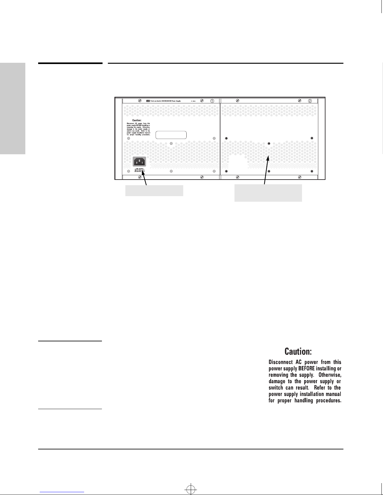
AC power connector
slot for installing optional
redundant power supply
Power Connector
The Switch 4000M and 8000M does not have a power switch; it is powered on
when connected to an active AC power source. The switch automatically
adjusts to any voltage between 100-127 and 200-240 volts and either 50 or 60
Hz. There are no voltage range settings required.
Slot for Redundant Power Supply
A second, load-sharing redundant power supply (HP ProCurve Switch 4000M/
8000M Power Supply, HP J4119A) can be installed in the back of the switch.
To provide true redundancy, this second power supply should be connected
to a different AC power source from the other supply. Then, if one AC power
source fails, the switch will continue to run.
The switch power supplies are hot swappable, but,
as indicated by the caution statement on the power
supply, it must be disconnected from AC power
before being installed or removed.
Because the switch can run on a single supply, removing a redundant supply
will not interrupt switch operation.
1-8
Page 15

4080~1.boo : 4080_1.FM Page 9 Thursday, July 2, 1998 1:43 PM
Introducing the HP ProCurve Switch 4000M and 8000M
Switch Features
The features of the Switch 4000M and 8000M include:
■ 10 slots for installing any of the available Switch Modules—as of this
printing, this includes:
• 8-port 10/100Base-TX Module (HP J4111A)
• 4-port 100Base-FX Module (HP J4112A)
• 1-port Gigabit-SX Module (HP J4113A)
• 4-port 10Base-FL Module (HP J4118A)
■ the modules can be installed in any order and in any combination and can
be “hot swapped”.
■ 3.8 Gbps backplane on both the Switch 4000M and Switch 8000M
■ plug-and-play networking—all ports are enabled—just connect the
network cables to active network devices and your switched network is
operational
■ automatic learning of the network addresses in the switch’s 8000-address
forwarding table, with configurable address aging value
■ configurable full-duplex operation of the 10 Mbps, 100 Mbps, and Gigabit
ports
■ easy management of the switch through several available interfaces:
• web browser interface—an easy to use built-in graphical interface
that can be accessed from common web browsers
• console interface—a full featured, easy to use, VT-100 terminal interface for out-of-band switch management, or for telnet access to the
switch
• HP TopTools for Hubs & Switches—an SNMP-based graphical interface that is used to manage your entire network, included with your
new switch
■ support for the Spanning Tree Protocol to eliminate network loops
■ support for up to 8 IEEE 802.1Q-compliant VLANs so you can divide the
attached end nodes into logical groupings that fit your business needs
■ support for many advanced features to enhance network performance—
see the Management and Configuration Guide that came with your switch
for a description
Switch Features
Introducing the HP ProCurve
Switch 4000M and 8000M
1-9
Page 16

4080~1.boo : 4080_1.FM Page 10 Thursday, July 2, 1998 1:43 PM
Introducing the HP ProCurve Switch 4000M and 8000M
Switch Operation Overview
Switch Operation Overview
Address Table Operation
Address Learning. As devices are connected to the switch ports, either
directly or through hubs or other switches that are connected to the switch,
Switch 4000M and 8000M
Introducing the HP ProCurve
the MAC addresses of those devices are learned automatically and stored in
the Switch 8000M’s 8000-entry address table. The switch also identifies the
number of the port on which each address is learned so it knows the network
location of each device.
Forwarding, Filtering, Flooding. When the switch receives a packet, it
determines the destination address, looks for the address in the address table.
Based on the port location of that address, the switch then determines whether
to forward, filter-out, or flood the packet.
■ forward - if the destination address is on a different port than the one on
which the packet was received, the packet is forwarded to the destination
port and on to the destination device.
■ filter out - if the destination address is on the same port as the one on
which the packet was received, the packet is filtered out. The switch
thereby isolates local traffic so the rest of the network connected to the
switch does not lose bandwidth dealing with unnecessary traffic. (You can
also configure filters on the switch that filter out packets based on specific
criteria.)
■ flood - whenever a new destination address is found in a received packet,
the destination address will not yet be in the switch’s address table and
the Switch 8000M cannot know whether to forward or filter out the
packet. In this case, it sends the packet out all the ports other than the
one on which it was received. This is referred to as “flooding”. When the
destination device receives the packet, it replies, and the switch learns
the new address from the reply packet. Then, all future packets destined
for that address are forwarded or filtered out appropriately.
1-10
Page 17

4080~1.boo : 4080_1.FM Page 11 Thursday, July 2, 1998 1:43 PM
Introducing the HP ProCurve Switch 4000M and 8000M
Switch Operation Overview
Network Moves and Changes. When devices are moved in the network,
and become connected to a different switch port, the Switch 4000M and 8000M
automatically recognizes the change and updates the address table with the
new port location of the device. Communication with the device is automatically maintained, without any address table manipulation being required.
Simultaneous Network Communications
In addition to traffic isolation benefits provided by the Switch 4000M and
8000M address table operation, the switch also enhances network performance because it can conduct multiple, simultaneous network connections.
Instead of sharing the network bandwidth, as in connections to a hub, each
connection has its own 10 Mbps, 100 Mbps, or 1000 Mbps bandwidth to use.
Effect of VLANs
If you configure multiple virtual LANs (VLANs) on the switch, each VLAN
behaves as a “logical switch” containing the switch ports that you assign to it.
Each logical switch behaves as an isolated broadcast domain, just as if it were
a separate physical switch. The forward, filter, and flood behavior described
for the physical switch above, operates the same for each of the logical
switches defined by the VLANs: packets are forwarded or flooded only to the
ports that are within a given VLAN. Just as for separate physical switches,
there is no communication between ports that are in separate VLANs unless
the VLANs are connected by an external router.
Introducing the HP ProCurve
Switch 4000M and 8000M
For more information on configuring VLANs and their behavior, see the HP
ProCurve Switch 8000M and 1600M Management and Configuration Guide
that came with your switch.
1-11
Page 18

4080~1.boo : 4080_1.FM Page 12 Thursday, July 2, 1998 1:43 PM
Page 19

4080~1.boo : 4080_2.FM Page 1 Thursday, July 2, 1998 1:43 PM
Installing the Switch 4000M and 8000M
The HP Switch 4000M and 8000M are easy to install units. They each come
with an accessory kit that includes the brackets for mounting the switch in a
standard 19-inch telco rack or an equipment cabinet, or on a wall, and with
rubber feet already attached so they can be securely located on a horizontal
surface. The brackets are designed to allow mounting the switches in a variety
of orientations.
This chapter shows you how to install your Switch 4000M and 8000M.
2
Installing the Switch 4000M
Included Parts
The Switch 4000M and 8000M have the following components shipped with
them:
■ HP ProCurve Switch 4000M and 8000M Installation Guide (5967-6916),
this manual
■
HP ProCurve Switch Management and Configuration Guide
(5967-6914 for the Switch 4000M; 5967-2142 for the Switch 8000M)
■
HP TopTools for Hubs & Switches - CD ROM and booklet
■ Customer Support/Warranty booklet
■ Accessory kit (5064-4213)
• two mounting brackets
• four 10 mm M4 screws to attach the mounting brackets to the switch
• four 5/8-inch number 12-24 screws to attach the switch to a rack
■ Console cable
■ Power cord, one of the following:
and 8000M
Australia/New Zealand
United Kingdom
China
Continental Europe
Denmark
Japan
Switzerland
United States/Canada/Mexico
(8120-6803)
(8120-6801)
(8120-8377)
(8120-6802)
(8120-6806)
(8120-6804)
(8120-6807)
(8120-6805)
2-1
Page 20

4080~1.boo : 4080_2.FM Page 2 Thursday, July 2, 1998 1:43 PM
Installing the Switch 4000M and 8000M
Installation Procedures
Installation Procedures
Summary
Follow these easy steps to install your switch. The rest of this chapter provides
details on these steps.
1. Prepare the installation site (page 2-4). Make sure that the physical
environment into which you will be installing the switch is properly
prepared including having the correct network cabling ready to connect
to the switch, and having a good location for the switch. Please see page
2-3 for some installation precautions.
2. Install switch modules (page 2-5). The Switch 4000M and the Switch
8000M have ten universal slots for installing any of the HP ProCurve
switch modules. The Switch 4000M has five 10/100Base-T modules preinstalled. Depending on where you will install the Switch 4000M and
and 8000M
Installing the Switch 4000M
8000M, it may be easier to install the modules first, but the modules are
“hot swappable”—they can also be installed and removed after the switch
is powered on.
3. (Optional) Install second power supply (page 2-6). The Switch
4000M and 8000M have a slot in the back for installing a second, loadsharing power supply. If you have purchased this supply, it may be easier
to install it before mounting the switch, although the power supplies are
“hot swappable”—they can be installed and removed after the switch
powered on.
2-2
4. Verify that the switch passes self test (page 2-8). This is a simple
process of plugging the switch into a power source and observing that the
LEDs on the switch’s front panel and on the modules show correct
operation.
5. Mount the switch (page 2-10). The Switch 4000M and 8000M can be
mounted in a 19-inch telco rack, in an equipment cabinet, on a wall, or on
a horizontal surface.
6. Connect power to the switch (page 2-14). Once the switch is mounted,
plug it in to the nearby main power source.
7. Connect the network devices (page 2-14). Using the appropriate
network cables, connect other switches, hubs, routers, computers,
servers, printers, and other network devices to the switch ports.
Page 21

4080~1.boo : 4080_2.FM Page 3 Thursday, July 2, 1998 1:43 PM
8. (Optional) Connect a console to the switch (page 2-15). You may
wish to modify the switch’s configuration, for example, to configure an IP
address so it can be managed using a web browser or from an SNMP
network management station. Configuration changes can be made easily
by through the switch’s console interface.
At this point, the switch is fully installed. See the rest of this chapter if you
need more detailed information on any of these installation steps.
Installation Precautions
Installing the Switch 4000M and 8000M
Installation Procedures
Warning
Cautions
Follow these precautions when installing your HP Switch 4000M and 8000M
The rack or cabinet should be adequately secured to prevent it from
becoming unstable and/or falling over.
Devices installed in a rack or cabinet should be mounted as low as possible,
with the heaviest device at the bottom and progressively lighter devices
installed above.
■ Make sure that the power source circuits are properly grounded, then
use the power cord supplied with the switch to connect it to the power
source.
If your installation requires a different power cord than the one supplied
with the switch, be sure to use a power cord displaying the mark of the
safety agency that defines the regulations for power cords in your
country. The mark is your assurance that the power cord can be used
safely with the switch.
■ Ensure that the switch does not overload the power circuits, wiring, and
over-current protection. To determine the possibility of overloading the
supply circuits, add together the ampere ratings of all devices installed
on the same circuit as the switch and compare the total with the rating
limit for the circuit. The maximum ampere ratings are usually printed on
the devices near the AC power connectors.
■ Do not install the switch in an environment where the operating ambient
temperature might exceed 55°C (131°F).
Make sure the air flow around the sides and back of the switch is not
■
restricted.
■ Make sure that for any switch slot into which no module is installed, the
cover plate is installed to cover the slot. A cover plate is required for safe
operation, and to ensure proper switch cooling.
Installing the Switch 4000M
and 8000M
2-3
Page 22

4080~1.boo : 4080_2.FM Page 4 Thursday, July 2, 1998 1:43 PM
Installing the Switch 4000M and 8000M
Installation Procedures
1. Prepare the Installation Site
■ Cabling Infrastructure - Ensure that the cabling infrastructure meets
the necessary network specifications. See the following table for cable
types and lengths, and see appendix B, “Cables and Connectors” for more
information:
Table 2-1. Summary of Cable Types to Use with the Switch
Port Type Cable Type Length Limits
and 8000M
Installing the Switch 4000M
10Base-T category 3, 4, or 5, 100 ohm
unshielded twisted-pair
(UTP)
10Base-FL 850 nm multimode fiber-
optic cables that are fitted
with ST connectors, and
conform to ISO/IEC 793-2
type B1 and ITU-T G.652
standards
100Base-TX category 5, 100-ohm UTP or
shielded twisted-pair (STP)
100Base-FX 1300 nm multimode fiber-
optic cables that are fitted
with SC connectors, and
conform to ISO/IEC 793-2
type B1 and ITU-T G.652
standards
• category 3, 4, or 5 - 100 meters
Note: Since the 10Base-T operation is through
10/100Base-TX ports, if you ever want to upgrade
the ports to 100Base-T, it would be best to cable
the ports initially with category 5 cable.
For connecting these ports to end nodes or other
MDI ports, use “straight-through” cable; for
connecting to MDI-X ports on hubs or other
switches, use “crossover” cable.
1 kilometer
100 meters
(See Note above on use of “straight-through”
and “cross-over” cables.)
• 412 meters for half-duplex connections
• 2 kilometers for full-duplex connections
Gigabit-SX 850 nm multimode fiber-
■ Installation Location - Before installing the switch, plan its location and
orientation relative to other devices and equipment. In the front of the
switch, allow at least 7.6 cm (3 inches) of space for the twisted-pair and
fiber-optic cabling. In the back of the switch, allow at least 3.8 cm (1 1/2
inches) of space for the power cord.
2-4
optic cables that are fitted
with SC connectors.
•62.5 µm cable - 220 meters
•50 µm cable - 500 meters
Page 23
4080~1.boo : 4080_2.FM Page 5 Thursday, July 2, 1998 1:43 PM
2.Install Switch Modules
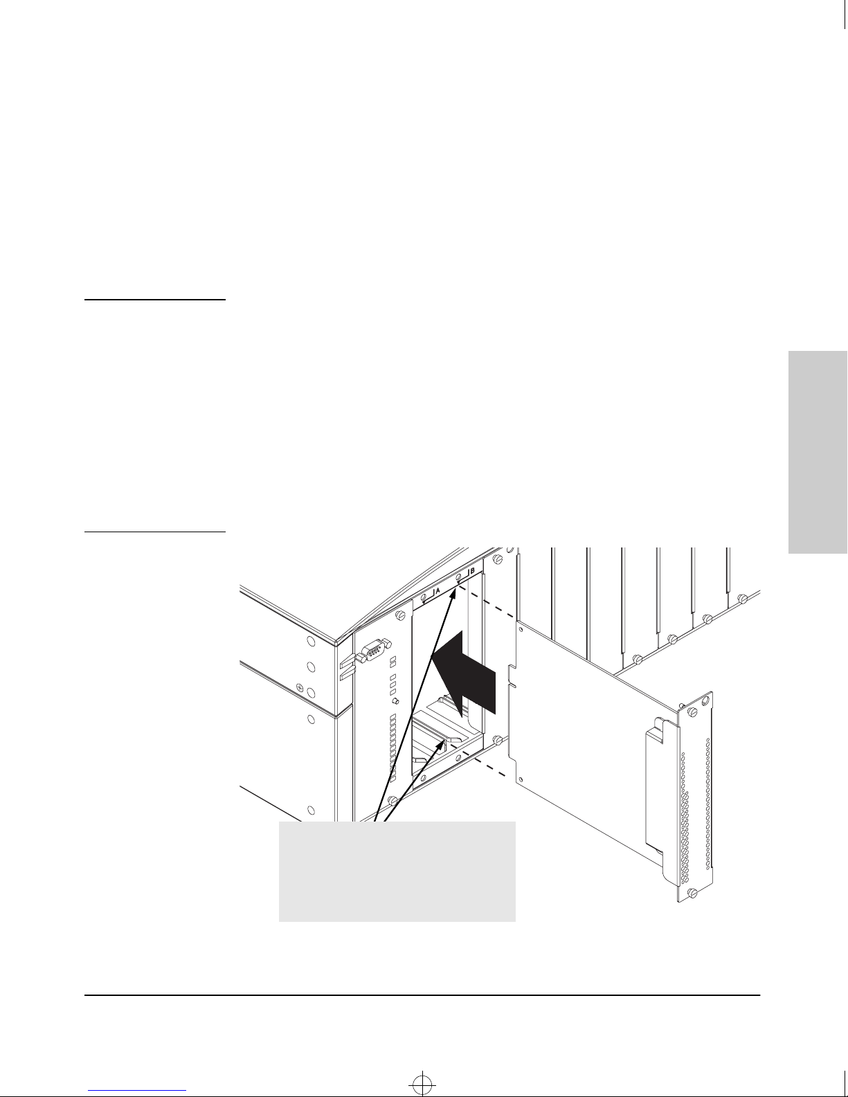
Install switch modules into the slots as shown in the illustration below. For
installation details, see the instructions in the manual that comes with the
module.
The slot cover can be removed, and the module can be installed with either a
flat-bladed or Torx T-10 screwdriver. Retain the slot cover for future use.
Installing the Switch 4000M and 8000M
Installation Procedures
Notes
Any of the supported switch modules can be installed in any of the slots.
■
■ The modules can be “hot swapped”, installed when the switch is powered
on, and normally will be immediately operational. But, if you are replacing
a module with a different type than what was previously installed in the
slot, the switch must be rebooted after the module is installed. See “Hot
Swapping the Switch Module” on page 2-17.
■ Make sure the module is fully installed and that you screw in the
retaining screws to secure the module in place.
■ If you do not use one or more of the slots, make sure that the slot cover
plate is still attached over the slot for safe operation and proper switch
cooling.
Installing the Switch 4000M
and 8000M
Insert module into the guides and slide it in
until it stops. Then press in firmly until the
module “snaps” into place and is flush with the
face of the switch.
the retaining screws on the module, but do not
overtighten them.
Then make sure you tighten
2-5
Page 24
4080~1.boo : 4080_2.FM Page 6 Thursday, July 2, 1998 1:43 PM
Installing the Switch 4000M and 8000M
Installation Procedures
3. (Optional) Install Second Power Supply
A second, load-sharing redundant power supply (HP ProCurve Switch 4000M/
8000M Power Supply, HP J4119A) can be installed in the back of the switch.
To provide true redundancy, this second power supply should be connected
to a different AC power source from the other supply. Then, if one AC power
source fails, the switch will continue to run. Each supply provides enough
power to operate a fully loaded switch, so even if one fails, the switch will
continue to operate normally.
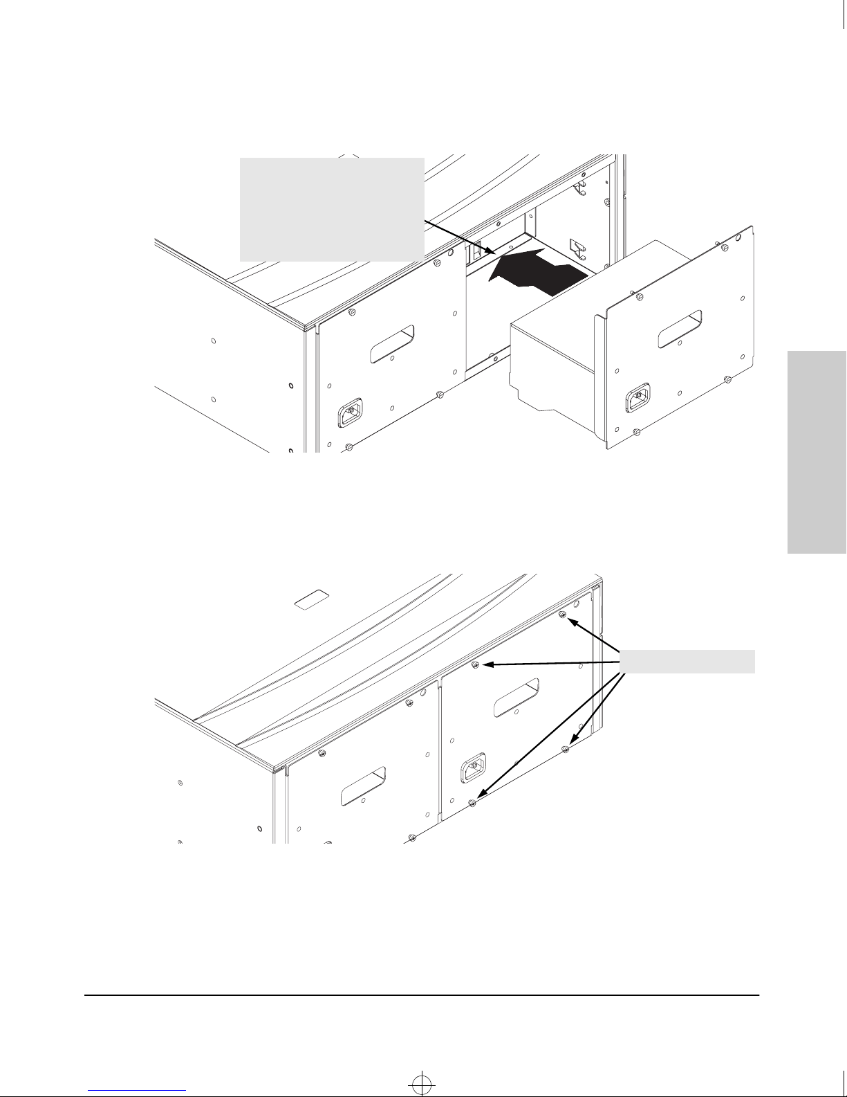
Install the second power supply into power slot number 2 as shown in the
illustration on the next page.
The slot cover can be removed with either a flat-bladed or Torx T-10 screwdriver. Retain the slot cover for future use.
and 8000M
Installing the Switch 4000M
Caution
The switch power supplies are hot swappable; they
can be installed while the switch is receiving power
from the supply in the other slot. But, as indicated
by the caution statement on the power supply, the
supply must not be connected to AC power
before being installed.
For installation details, see the instructions in the manual that comes with the
power supply.
2-6
Page 25
4080~1.boo : 4080_2.FM Page 7 Thursday, July 2, 1998 1:43 PM
Insert the power supply into the
opening, lower it until it rests on the
bottom of the switch chassis, then
slide it all the way in until it connects
to the switch. The power supply
face plate will be flush with the back
of the switch.
Installing the Switch 4000M and 8000M
Installation Procedures
Installing the Switch 4000M
Once the power supply is installed, make sure you tighten the four retaining
screws that hold it in place. The screws can be tightened with either a flatbladed or Torx T-10 screwdriver. Be careful not to overtighten the screws.
tighten the four screws
and 8000M
2-7
Page 26
4080~1.boo : 4080_2.FM Page 8 Thursday, July 2, 1998 1:43 PM
Installing the Switch 4000M and 8000M
Installation Procedures
4. Verify the Switch Passes Self Test
After you have installed any modules and the optional second power supply,
but before mounting the switch in its network location, you should first verify
that it is working properly by plugging it into a power source and verifying
that it passes its self test.
If you have installed a second power supply, repeat these procedures with the
second power supply to verify that it works correctly too.
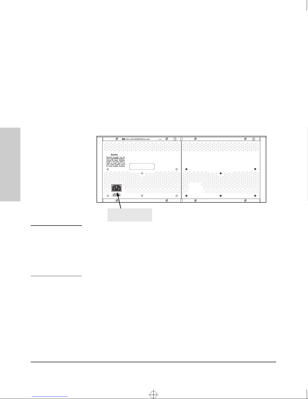
1. Connect the power cord supplied with the switch to the power connector
on the back of the switch, and then into a properly grounded electrical
outlet.
and 8000M
Installing the Switch 4000M
Note
Connect power cord to
power connector
The Switch 4000M and 8000M do not have a power switch. They are powered
on when the power cord is connected to the switch and to a power source.
If your installation requires a different power cord than the one supplied with
the switch, be sure to use a power cord displaying the mark of the safety
agency that defines the regulations for power cords in your country. The mark
is your assurance that the power cord can be used safely with the switch.
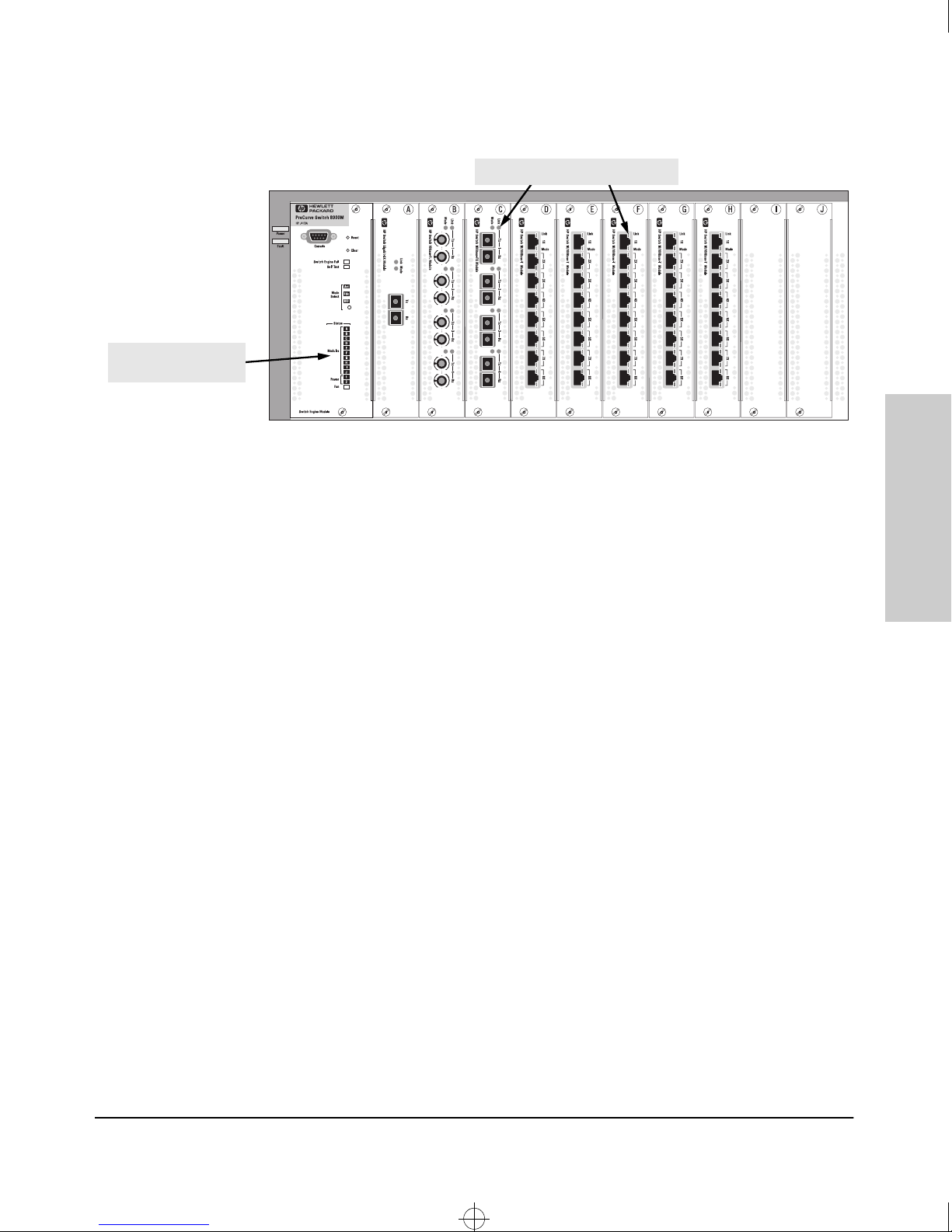
2. Check the LEDs on the Switch Engine Module and on each of the switch
modules. The LED behavior is described on the next page.
If the LED display is different than what is described, especially if any
Fault LEDs stay on for more than approximately 80 seconds or they start
flashing, the self test has not completed correctly. Refer to chapter 3,
“Troubleshooting” for diagnostic help.
2-8
Page 27
4080~1.boo : 4080_2.FM Page 9 Thursday, July 2, 1998 1:43 PM
switch module LEDs near each port
Switch Engine Module
LEDs
When the switch is powered on, it performs its diagnostic self test. The
self test takes approximately 35 to 70 seconds to complete, depending on
the number and type of modules installed in the switch.
Installing the Switch 4000M and 8000M
Installation Procedures
Installing the Switch 4000M
and 8000M
LED Behavior:
During the self test:
• Initially, Power and Fault, and all the Switch Engine and switch
module LEDs are on.
• After approximately 3 seconds most of the LEDs go off and then may
come on again during phases of the self test. For the duration of the
self test, the Self Test LED stays on.
When the self test completes successfully:
• The large Power LED stays on, and the Status LEDs on the Switch
Engine Module stay on for the modules installed: one for each switch
module installed, one for each power supply installed, and the Fan
LED.
• The large Fault LED goes off, and the Switch Engine Fail and
Self Test LEDs go off.
• The port LEDs on the switch modules go into their normal operational
mode:
– If the ports are connected to active network devices, the Link
LEDs stay on and the Mode LEDs behave according to the mode
selected. In the default mode (Activity), the Mode LEDs should
flicker showing network activity on the port.
– If the ports are not connected to active network devices, the LEDs
will stay off.
2-9
Page 28
4080~1.boo : 4080_2.FM Page 10 Thursday, July 2, 1998 1:43 PM
Installing the Switch 4000M and 8000M
Installation Procedures
5. Mount the Switch
After the modules and optional power supply are installed and you have
verified that the switch passes self test, you are ready to mount the switch in
a stable location. The Switch 4000M and 8000M can be mounted in these ways:
■ in a rack or cabinet
■ on a horizontal surface
■ on a wall
Rack or Cabinet Mounting
The Switch 4000M and 8000M are designed to be mounted in any EIA-standard
19-inch telco rack or in an equipment cabinet such as a server cabinet.
and 8000M
Installing the Switch 4000M
Warning
For safe operation, please read the mounting precautions on
page 2-3 before mounting the switch.
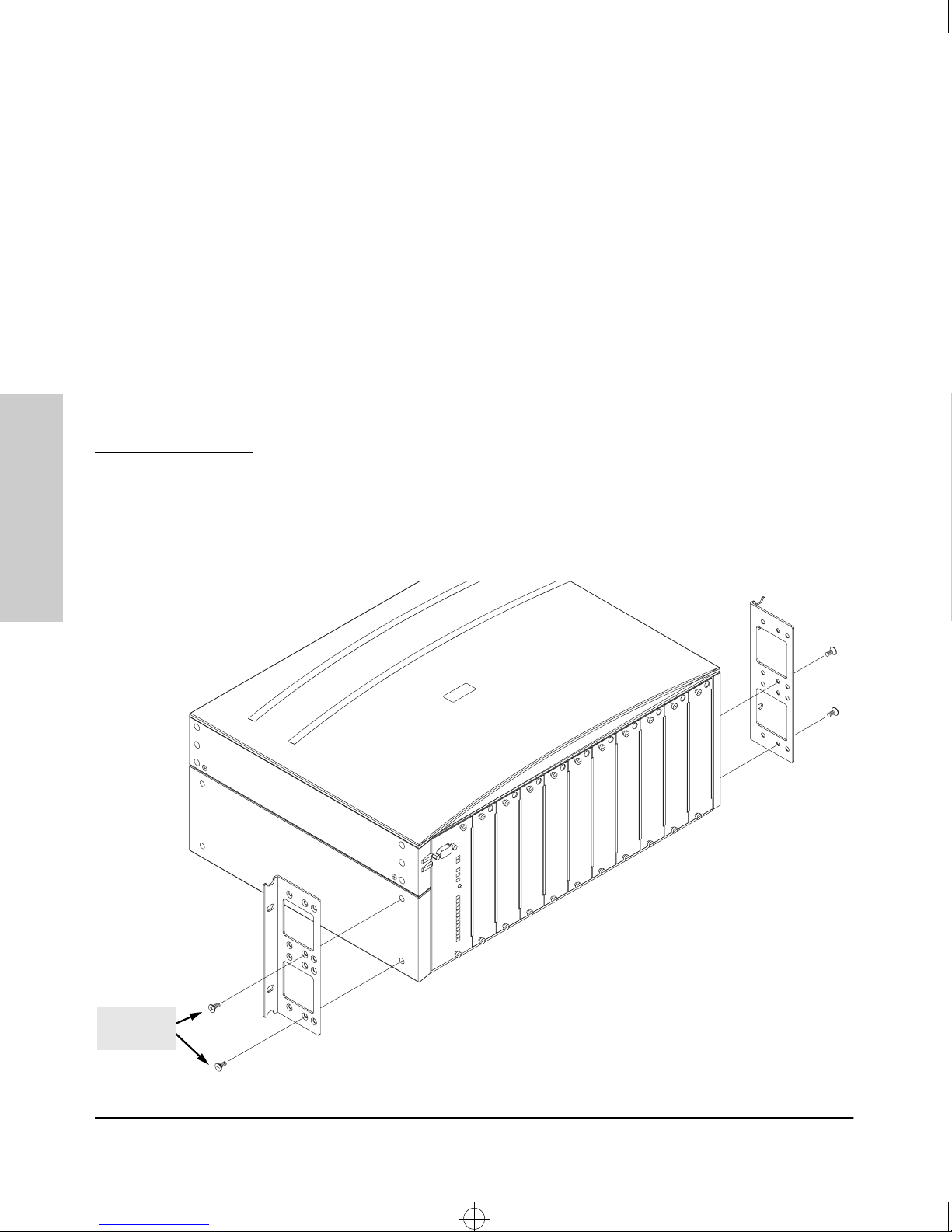
1. Use a #1 Phillips (cross-head) screwdriver and attach the mounting
brackets to the switch with the included 10-mm M4 screws.
10 mm
M4 screws
2-10
Page 29
4080~1.boo : 4080_2.FM Page 11 Thursday, July 2, 1998 1:43 PM
Installing the Switch 4000M and 8000M
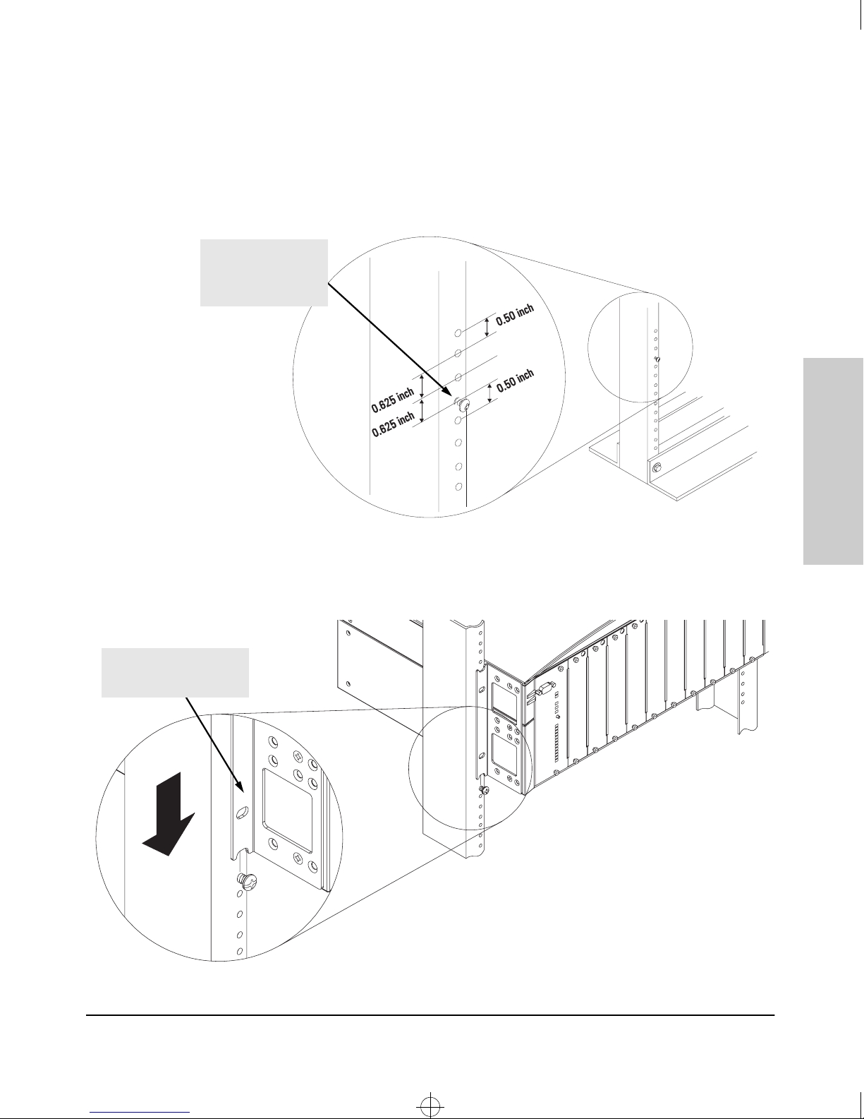
2. Partially install a screw (5/8-inch number 12-24) into the top hole of a pair
of holes that are 0.5 inches apart in each rack/cabinet upright as shown
in the illustration below. Ensure that the screws are at the same level in
each upright.
.
partially install a screw
into the top hole of a
close (0.5-inch) pair on
both sides of the rack
Installation Procedures
Installing the Switch 4000M
lower the switch with
mounting brackets onto the
partially installed screw
and 8000M
3. Place the switch in the rack and lower it so the notches in the bottom of
the bracket slide onto the screws, then tighten these screws.
2-11
Page 30
4080~1.boo : 4080_2.FM Page 12 Thursday, July 2, 1998 1:43 PM
Installing the Switch 4000M and 8000M
Installation Procedures
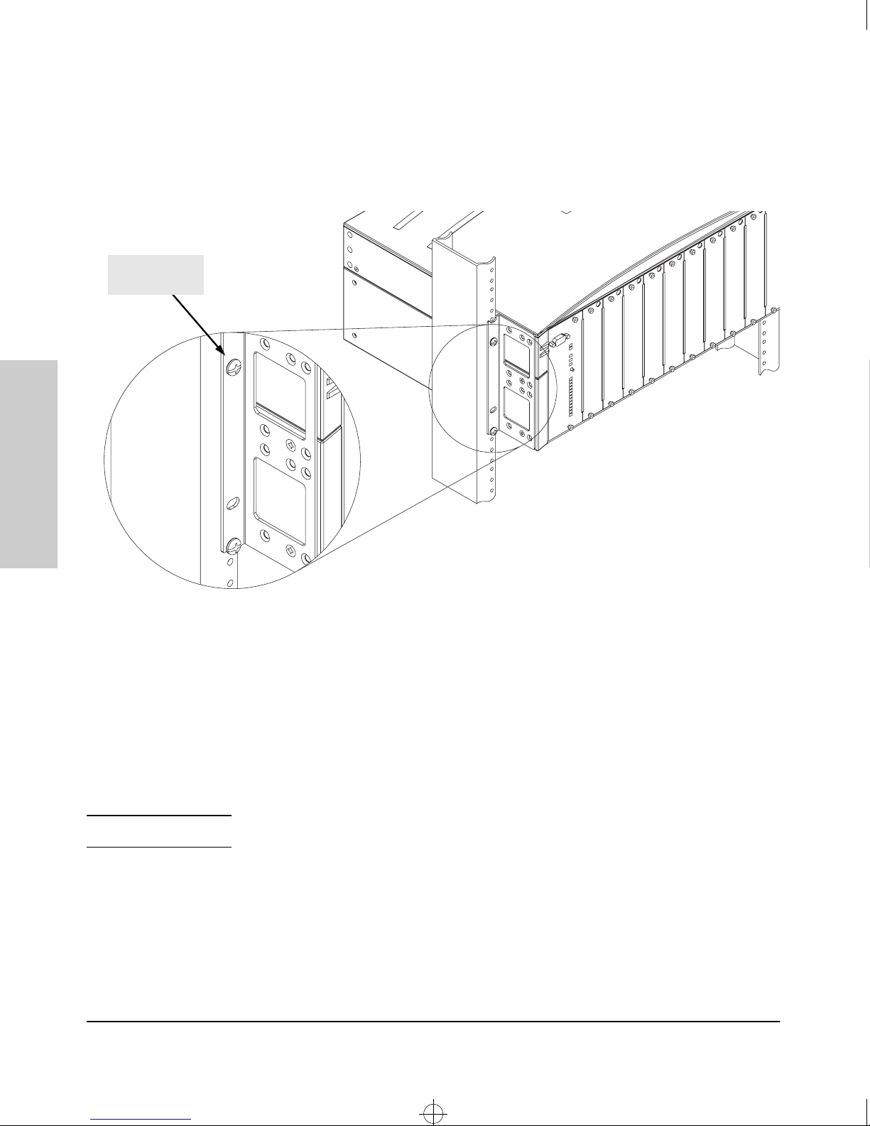
4. Install the other number 12-24 screw into the upper hole in each bracket.
Tighten these screws.
install additional
screw
and 8000M
Installing the Switch 4000M
Note
Horizontal Surface Mounting
Place the switch on a table or other horizontal surface. Use a sturdy surface
in an uncluttered area. You may want to secure the networking cables and
switch power cord to the table legs or other part of the surface structure to
help prevent people from tripping over the cords.
Make sure the air flow is not restricted around the sides and back of the switch.
2-12
Page 31
4080~1.boo : 4080_2.FM Page 13 Thursday, July 2, 1998 1:43 PM
Installing the Switch 4000M and 8000M
Wall Mounting
The mounting brackets supplied with the switch allow you to mount it on a
wall. You can mount it in any orientation that places the power supplies facing
against the wall and the modules facing out. The orientation shown in the
illustrations is commonly referred to as a “bookshelf” mount.
Installation Procedures
Caution
For safety considerations, you should not mount the switch on a wall such
that either the power supplies or the modules are facing downward.
Additionally, the switch should be mounted only to a wall or wood surface
that is at least 1/2-inch plywood or its equivalent.
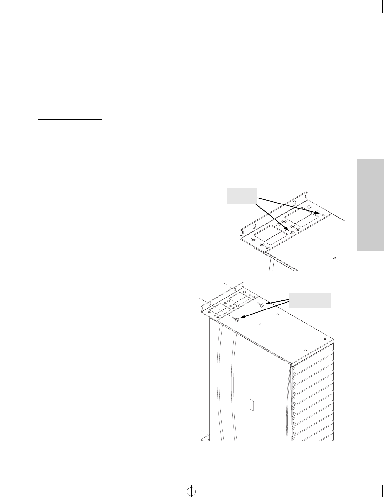
1. Use a #1 Phillips (cross-head)
screwdriver and attach the
10-mm M4
screws
mounting brackets to the switch
with the included 10-mm M4
screws.
2. Attach the
switch to the
wall or wood
surface with four
5/8-inch number
5/8-inch number
12 wood screws
12 wood screws
or larger (not
included).
Installing the Switch 4000M
and 8000M
2-13
Page 32

4080~1.boo : 4080_2.FM Page 14 Thursday, July 2, 1998 1:43 PM
Installing the Switch 4000M and 8000M
Installation Procedures
6. Connect the Switch to a Power Source
1. Plug the included power cord into the switch’s power connector and into
a nearby properly grounded AC power source.
If you have installed a redundant power supply module into the switch, it
should be connected to a separate AC power source. Then, if there is a
power outage from one of the AC sources, the switch will continue to
operate by power coming from the other source.
See the HP ProCurve Switch 4000M/8000M Power Supply Installation
Guide for additional information.
2. Re-check the LEDs during self test. See “LED Behavior” on page 2-9.
and 8000M
Installing the Switch 4000M
7. Connect the Network Devices
The type of network connections you will need to use depends on the types
of switch modules you have installed in your Switch 4000M and 8000M. See
the documentation accompanying the modules for cabling configurations and
procedures for those modules.
The module documentation will also cover troubleshooting procedures, but,
in general for all the modules, when a network cable from an active network
device is connected to the switch module port, the Link LED for that port
should go on. If the Link LED does not go on when the network cable is
connected to the port, use the table below to help solve the problem.
Condition Diagnostic Tip
Port LED is
still off when
a cable is
connected
Try the following procedures:
• For the indicated port, verify that both ends of the cabling, at the switch and the connected
device, are snug.
• Verify the connected device and switch are both powered on and operating correctly.
• Verify that you have used the correct cable type for the connection.
- for twisted-pair connections, in general, for connecting to an end node, use “straight through” cable; for connecting to hubs or other switches, use “crossover” cable.
- for fiber-optic connections, verify that the transmit port on the switch is connected to
the receive port on the connected device, and the switch receive port is connected to
the transmit port on the connected device.
• Verify that the port has not been disabled through a switch configuration change.
You can use the console interface, or, if you have configured an IP address on the switch,
use the web browser interface, or HP TopTools for Hubs & Switches network management
software to determine the state of the port and re-enable the port if necessary.
• If the other procedures don’t resolve the problem, try using a different port or a different
cable.
2-14
Page 33

4080~1.boo : 4080_2.FM Page 15 Thursday, July 2, 1998 1:43 PM
Installing the Switch 4000M and 8000M
8. (Optional) Connect a Console to the Switch
The Switch 4000M and 8000M have a full-featured, easy to use console
interface for performing the following tasks:
■ Monitor switch and port status and observe network activity counters
■ Modify the switch’s configuration
■ Read the event log and access diagnostic tools to help in troubleshooting
■ Download new software to the switch
Add passwords to control access to the switch from the console, web
■
browser interface, and network management stations
The console can be accessed through these methods:
■
Out-of-band: The Switch 4000M and 8000M come with a serial cable for
connecting a PC or VT-100 terminal to be used as a console directly to the
switch. If the PC or terminal has a 25-pin serial connector, you can use a
readily available 9-pin to 25-pin serial cable, or attach a 9-to-25 pin
“straight-through” adapter to the end of the supplied cable.
■ In-Band: Access the console using telnet from a PC or UNIX station on
the network, and a VT-100 terminal emulator. This method requires that
you first configure the switch with an IP address and subnet mask by using
either out-of-band console access or through DHCP/Bootp.
Installation Procedures
Installing the Switch 4000M
and 8000M
The Switch 4000M and 8000M can simultaneously support one out-of-band
console session through the Console Port and one in-band telnet console
session.
Terminal Configuration
To connect a console to the switch, configure the PC terminal emulator as a
VT-100 or DEC VT-100 (ANSI) terminal, or use a VT-100 terminal and configure
it to operate with these settings:
• any baud rate from 2400 to 115200 (the switch automatically senses
the speed)
• 8 data bits, 1 stop bit, no parity, XON/XOFF flow control
• For Windows Terminal program, also disable (uncheck) the “Use
Function, Arrow, and Ctrl
If you want to operate the console using a different configuration, make sure
you change the settings on both the terminal and on the switch. Change the
switch settings first, then change the terminal settings, and reestablish the
console session.
Keys for Windows” option.
2-15
Page 34
4080~1.boo : 4080_2.FM Page 16 Thursday, July 2, 1998 1:43 PM
Installing the Switch 4000M and 8000M
Installation Procedures
Direct Console Access
and 8000M
Installing the Switch 4000M
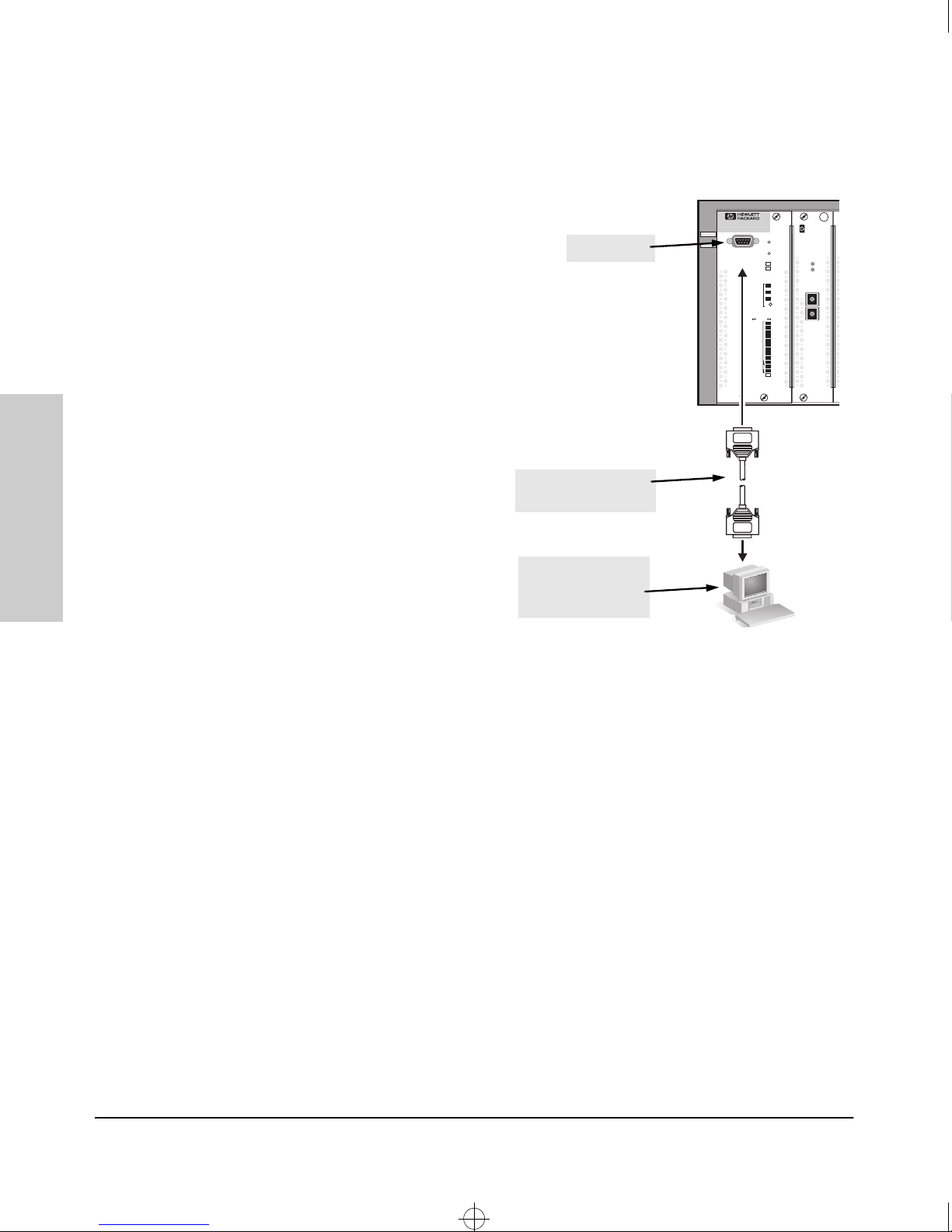
To connect a console to the
switch, follow these steps:
1. Connect the PC or
terminal to the switch’s
Console Port using the
console cable included
with the switch. (If your
PC or terminal has a 25pin serial connector, first
attach a 9-pin to 25-pin
console port
Switch8000
HPJ4110A
Power
SwitchEngine Module
ConsoleFault
SwitchEngine Fail
Reset
Clear
SelfTest
Act
Mode
Fdx
Select
100
Status
A
B
Mode
C
Select
D
E
F
G
H
I
J
1
Power
2
Fan
“straight-through”
adapter at one end of the
console cable.)
2. Turn on the terminal or
console cable supplied
with the switch
PC’s power and, if using a
PC, start the PC terminal
program.
3. Press [Enter] two or three
PC running a terminal
emulator program, or
a VT-100 terminal
times and you will see the
copyright page and the
message “Press any key
to continue”. Press a key, and you will then see the switch console Main
Menu.
A
A
HPSwitch Gigabit-SX Module
Link
Mode
Tx
Rx
2-16
Telnet Console Access
To access the switch through a telnet session, follow these steps:
1. Make sure the switch is configured with an IP address and that the switch
is reachable from the telnet workstation (for example by using a Ping
command to the switch’s IP address)
2. Start the telnet program and connect to the switch’s IP address.
3. You will see the copyright page and the message “Press any key to
continue”. Press a key, and you will then see the switch console Main
Menu.
If you want to continue with console management of the switch at this time
through either a direct connection or a telnet session, refer to the Management
and Configuration Guide that came with your switch.
Page 35

4080~1.boo : 4080_2.FM Page 17 Thursday, July 2, 1998 1:43 PM
Installing the Switch 4000M and 8000M
Hot Swapping Switch Modules
The switch modules can be “hot swapped”, that is installed or replaced while
the switch is powered on. The procedures differ slightly, though between
adding new modules to an empty slot or replacing modules with the same type,
and exchanging the module with a different type.
Adding or Replacing Modules
Hot Swapping Switch Modules
If a module has to be replaced with one of the same type, or you are expanding
the switch capability by adding a module in a slot where one was not previously installed, the replaced or new module is immediately operational; there
is no interruption to the switch operation.
Changing the Module Type
If you exchange a module with one of a different type though, for example a
Gigabit-SX module is installed in place of a 100Base-FX module that was in
the slot, the switch must be rebooted after the new module is installed so the
switch processor can properly initialize and configure the new module type.
You can reboot the switch by any of these methods:
■ select the Reset or Reboot option from the console, web browser inter-
face, or HP TopTools for Hubs & Switches
■ press the Reset button on the switch
■ unplug and plug in the power cord (power cycle)
Until the switch is rebooted, the module will not operate, the Module Status
LED will continue to flash, and all the LEDs on the module will stay on
continuously.
Installing the Switch 4000M
and 8000M
2-17
Page 36

4080~1.boo : 4080_2.FM Page 18 Thursday, July 2, 1998 1:43 PM
Installing the Switch 4000M and 8000M
Where to Go From Here
Where to Go From Here
Your switch is now correctly installed and is able to send and receive data
between end nodes, servers, and printers.
The Switch 4000M and 8000M are plug-and-communicate network devices
requiring no configuration. If you wish to manage the switch from an SNMPbased network management station, through the web browser interface, or
over a telnet console session, you will need to configure the IP address on the
switch. See the Management and Configuration Guide that came with your
switch for information on how to use the switch console interface to configure
the IP address.
and 8000M
Installing the Switch 4000M
2-18
Page 37

4080~1.boo : 4080_3.FM Page 1 Thursday, July 2, 1998 1:43 PM
Troubleshooting
This chapter describes how to troubleshoot your Switch 4000M and 8000M.
Note that this document describes troubleshooting mostly from a hardware
perspective. You can perform more in-depth troubleshooting using the software tools available with the switch, including the full-featured console
interface, the built-in web browser interface, and HP TopTools for Hubs &
Switches, the SNMP-based network management tool. See the chapter 8,
“Troubleshooting” of the Management and Configuration Guide included
with your switch for more information.
3
This chapter describes the following:
■ basic troubleshooting tips (page 3-2)
■ diagnosing with the LEDs (page 3-4)
■ Proactive Networking tools (page 3-7)
Hardware Diagnostic tests (page 3-8)
■
■ restoring the factory default configuration (page 3-10)
■ HP Customer Support Services (page 3-11)
Troubleshooting
3-1
Page 38

4080~1.boo : 4080_3.FM Page 2 Thursday, July 2, 1998 1:43 PM
Troubleshooting
Basic Troubleshooting Tips
Basic Troubleshooting Tips
Most problems are caused by the following situations. Check for these items
first when starting your troubleshooting:
■ Incorrect switch-to-switch or switch-to-hub connections. If you
have connected your switch to another switch or a hub by using twistedpair cable from an RJ-45 MDI-X connector on your switch to the an MDIX connector on the other switch or hub, you must use a crossover cable.
If you have used a straight-through cable, the connection will not work.
The LED for the port you are using will not come on when you connect
the cable.
Troubleshooting
Most switch and hub ports are wired as MDI-X ports, so for these switchto-switch or switch-to-hub connections use a crossover cable. LAN
adapters in end nodes are normally wired as MDI ports as are some ports
on hubs and switches. For connections from the switch to these MDI
ports, use a straight-through cable. See appendix B, “Cables and
Connectors” for pinouts and correct cable wiring for crossover and
straight-through twisted-pair cables.
■ Faulty or loose cables. Look for loose or obviously faulty connections.
If they appear to be OK, make sure the connections are snug. If that does
not correct the problem, try a different cable.
■ Non-standard cables. Non-standard and miswired cables may cause
numerous network collisions and other network problems, and can seriously impair network performance. Use a new correctly-wired cable or
compare your cable to the cable in appendix B, “Cables and Connectors”
for pinouts and correct cable wiring. A category 5 cable tester is a
recommended tool for every 100Base-T network installation.
■ Improper Network Topologies. It is important to make sure you have
a valid network topology. Common topology faults include excessive
cable length and excessive repeater delays between end nodes. If you have
network problems after recent changes to the network, change back to
the previous topology. If you no longer experience the problems, the new
topology is probably at fault. Refer to the Network Design Guide for
topology configuration guidelines. This guide can be found online at the
HP World Wide Web site for networking products,
http://www.hp.com/go/network_city under the
[Tech Library] button.
3-2
Page 39

4080~1.boo : 4080_3.FM Page 3 Thursday, July 2, 1998 1:43 PM
In addition, you should make sure that your network topology contains
no data path loops. Between any two end nodes, there should be only one
active cabling path at any time. Data path loops will cause broadcast
storms that will severely impact your network performance.
If you wish to build redundant paths between important nodes in your
network to provide some fault tolerance, you should enable Spanning
Tree Protocol support on the switch. This ensures that only one of the
redundant paths is active at any time, thus avoiding data path loops.
Spanning Tree can be enabled through the switch console, the web
browser interface, or HP TopTools for Hubs and Switches.
The Switch 8000M also supports Switch Meshing which allows multiple
data paths though a switched network to be active simultaneously for
enhanced network bandwidth. See the Management and Configuration
Guide that came with your switch for more information on Spanning Tree
and on Switch Meshing.
Troubleshooting
Basic Troubleshooting Tips
Troubleshooting
3-3
Page 40
4080~1.boo : 4080_3.FM Page 4 Thursday, July 2, 1998 1:43 PM
Troubleshooting
Diagnosing with the LEDs
Diagnosing with the LEDs
Tables 3-1 shows LED patterns on the switch and the switch modules that
indicate problem conditions.
1. Check in the table for the LED pattern that you see on your switch
2. Refer to the corresponding diagnostic tip on the next few pages.
Table 3-1. LED Error Indicators
LED Pattern Indicating Problems
Switch Engine
Fail
Module Status
module)
(one LED per
(one LED per
Power Status
power supply)
Self Test
Power
Off with
power
cord
plugged
in
Fault
* * *****
Fan Status
Diagnostic
Tips
Port Link
➊
Troubleshooting
On Prolonged OnProlonged OnProlonged
On
On Flashing
On Flashing
On Off Off Off Flashing
On Flashing
On Flashing
On Off Off Off On * * Off with
* This LED is not important for the diagnosis.
†
The flashing behavior is an on/off cycle once every 1.6 seconds, approximately.
†
†
†
†
Flashing
†
Flashing
Off Flashing
Off Off * Flashing
Off Off * * Flashing
†
†
****
****
Flashing
†
†
***
***
†
**
†
connected
*
cable
➋
➌
➍
➎
➏
➐
➑
3-4
Page 41

4080~1.boo : 4080_3.FM Page 5 Thursday, July 2, 1998 1:43 PM
Diagnostic Tips:
Tip
Number
Problem Solution
Troubleshooting
Diagnosing with the LEDs
➊
➋
➌
The power supplies
installed in the
switch are not
plugged into active
AC power sources,
or the power supply
may have failed.
A switch hardware
failure has
occurred. All the
LEDs will stay on
indefinitely.
The switch has
experienced a
software failure
during self test.
1. Verify that the power cord is plugged into an active power source and to the
switch. Make sure these connections are snug.
2. Try power cycling the switch by unplugging and plugging the power cord back in.
3. If the Power LED is still not on, verify that the AC power source works by plugging
another device into the outlet. Or try plugging the switch into a different outlet or
try a different power cord.
If the power source and power cord are OK and this condition persists, the switch
power supply may have failed. Call your HP-authorized LAN dealer, or use the
electronic support services from HP to get assistance. See the Customer Support/
Warranty card for more information.
Try power cycling the switch. If the fault indication reoccurs, the switch may have
failed. Call your HP-authorized LAN dealer, or use the electronic support services
from HP to get assistance. See the Customer Support/Warranty card for more
information.
1. Try resetting the switch by pressing the Reset button on the front of the switch,
or by power cycling the switch.
2. If the fault indication reoccurs, attach a console to the switch (as indicated in
chapter 2) and configure it to operate at 9600 baud. Then, reset the switch.
Messages should appear on the console screen and in the console log identifying
the error condition. You can view the console log at that point by selecting it from
the console Main Menu.
If necessary to resolve the problem, contact your HP-authorized LAN dealer, or use
the electronic support services from HP to get assistance. See the Customer
Support/Warranty card for more information.
Troubleshooting
➍
The module
installed in the slot
that corresponds to
the letter that is
flashing is not
installed properly,
has experienced a
self test fault, or has
become partly
removed during
switch operation.
The modules are all tested whenever the switch is powered on, or reset (through
the Reset button on the switch, or the Reboot or Reset options in the console or web
browser interface), and when they are hot swapped (installed when the switch is
powered on).
Under this error condition, the following events also occur:
• All the LEDs on the module stay on until the error is resolved.
• The switch software, including console and web browser access will not be
operational for approximately one minute from the time the module gets into this
condition.
T ry reinstalling the module. You can do this without having to power down the switch.
When the module is reinstalled, it will be retested automatically. Make sure to screw
in the retaining screws so that the module cannot be inadvertently pulled out by
pulling on the network cables.
If the fault indication reoccurs, the module may have failed. Remove the module from
the switch and replace it with another module, or recover the slot with the cover
plate. Call your HP-authorized LAN dealer, or use the electronic support services
from HP to get assistance. See the Customer Support/Warranty card for more
information.
3-5
Page 42

4080~1.boo : 4080_3.FM Page 6 Thursday, July 2, 1998 1:43 PM
Troubleshooting
Diagnosing with the LEDs
Tip
Number
Problem Solution
➎
➏
➐
In the slot
corresponding to
the letter that is
flashing, a module
was installed that is
a different type
than the previously
installed module,
and the switch has
not yet been reset.
A fault condition
has been detected
on the power
supply installed in
the slot
corresponding to
the flashing
number.
One or more of the
switch cooling fans
may have failed.
When you “hot swap” modules in the switch slots, if you install a different module
type than the one that was previously installed in the slot, you must reset the switch
so the switch processor can properly initialize and configure the new module type.
The flashing LED informs you that this change of module types has occurred. The
module will not work properly until the switch is reset as indicated by all the module’s
LEDs staying on until the switch is reset.
You can reset the switch by any of these methods:
• pressing the Reset button on the Switch Engine Module
• power cycling the switch
• selecting the reset or reboot option from the console, web browser interface, or
HP TopTools.
Try removing and reinstalling the supply.
Caution: Make sure that the AC power cord is disconnected from the supply before
removing and reinstalling the supply.
Reconnect the power supply to the AC power source. If the error indication reoccurs
after the supply is reinstalled, the power supply may be faulty. Call your HPauthorized LAN dealer, or use the electronic support services from HP to get
assistance. See the Customer Support/Warranty card for more information.
T ry disconnecting power from the switch and wait a few moments. Then reconnect
the power to the switch and check the LEDs again. If the error indication reoccurs,
one or more of the fans has failed. The switch has three fans and may continue to
operate OK under this condition if the ambient temperature does not exceed normal
room temperature, but for best operation, the switch should be replaced. Contact
your HP-authorized LAN dealer, or use the electronic support services from HP to
get assistance. See the Customer Support/Warranty card for more information.
Troubleshooting
3-6
➑
The network
connection is not
working properly.
Try the following procedures:
• For the indicated port, verify that both ends of the cabling, at the switch and the
connected device, are snug.
on
• Verify the connected device and switch are both powered
correctly.
• Verify that you have used the correct cable type for the connection.
- for twisted-pair connections, in general, for connecting to an end node, use
“straight- through” cable; for connecting to MDI-X ports on hubs or other
switches, use “crossover” cable.
- for fiber-optic connections, verify that the transmit port on the switch is connected to the receive port on the connected device, and the switch receive port
is connected to the transmit port on the connected device.
• Verify that the port has not been disabled through a switch configuration change.
You can use the console interface, or, if you have configured an IP address on
the switch, use the web browser interface, or HP TopTools for Hubs & Switches
network management software to determine the state of the port and re-enable
the port if necessary.
• If the other procedures don’t resolve the problem, try using a different port or a
different cable.
and operating
Page 43

4080~1.boo : 4080_3.FM Page 7 Thursday, July 2, 1998 1:43 PM
Proactive Networking
The Switch 4000M and 8000M have built-in management capabilities that
proactively help you manage your network including:
■ finding and helping you fix the most common network error conditions (for
example, faulty network cabling, and non-standard network topologies)
informing you of the problem with clear, easy-to-understand messages
■
■ recommending network configuration changes to enhance the perfor-
mance of your network
The following interfaces provide tests, indicators, and an event log that can
be used to monitor the switch and its network connections and to help you
take advantage of these proactive networking features:
■ HP TopTools for Hubs & Switches - an SNMP-based network management
tool that is included with your switch
■ A graphical web browser interface that you can use to manage your switch
from a PC running a supported web browser, for example Microsoft
Internet Explorer, and Netscape Communicator.
■ A full-featured easy-to-use console interface that you can access by
merely connecting a standard terminal or PC running a terminal emulator
to the switch’s console port. The cable to make that connection is
provided with your switch. The console interface is also accessible
through a telnet connection.
Troubleshooting
Proactive Networking
Troubleshooting
See chapter 8, “Troubleshooting”, in the Management and Configuration
Guide that came with your switch for more information on using these
software tools to diagnose and manage your switch.
3-7
Page 44

4080~1.boo : 4080_3.FM Page 8 Thursday, July 2, 1998 1:43 PM
Troubleshooting
Hardware Diagnostic Tests
Hardware Diagnostic Tests
Testing the Switch by Resetting It
If you believe that the switch is not operating correctly, you can reset the
switch to test its circuitry and operating code. To reset a switch, either:
■ Unplug and plug in the power cord (power cycling)
■ Press the Reset button on the front of the switch
Power cycling the switch and pressing the Reset button both cause the switch
to perform its power-on self-test, which almost always will resolve any temporary operational problems. These reset processes also cause any network
traffic counters to be reset to zero, and cause the System Up Time timer to
reset to zero. None of the reset procedures cause any changes to the switch
configuration.
Troubleshooting
Checking the Switch LEDs
The self-test passes if the Fault and Self Test LEDs on the front of the switch
go off after approximately 30 to 70 seconds depending on the number and type
of modules installed in the switch. If these LEDs stay on longer than 80 seconds
or begin flashing, the switch may have to be replaced.
See “Diagnosing With the LEDs” on page 3-4 for information on interpreting
the LED patterns.
Checking Console Messages
Useful diagnostic messages may be displayed on the console screen when the
switch is reset. As described in chapter 2 under step 8, “Connect a Console to
the Switch”, connect a PC running a VT-100 terminal emulator program or a
standard VT-100 terminal to the switch’s Console Port and configure it to run
at 9600 baud, and with the other terminal communication settings shown on
page 2-15. Then, when you reset the switch, note the messages that are
displayed.
3-8
Page 45

4080~1.boo : 4080_3.FM Page 9 Thursday, July 2, 1998 1:43 PM
Testing Twisted-Pair Cabling
If you think the cable should work but still isn’t working, it may not be
compatible with the IEEE 802.3 Type 10Base-T or 100Base-T standards. The
twisted-pair cables attached to the Switch 4000M and 8000M must be compatible with these standards.To verify that your cable is compatible with these
standards, use a qualified cable test device.
HP also offers a wire testing service. Contact your HP-authorized LAN dealer
or your local HP sales office for more information.
Troubleshooting
Hardware Diagnostic Tests
Note
Make sure that you are using the correct cabling type for each connection.
The switch UTP ports are all wired as MDI-X. For connecting end nodes and
other MDI-type devices, use “straight-through” cable. For connecting hubs,
other switches, and other MDI-X devices, use “crossover” cable. See appendix
B, “Cables and Connectors” for the pinouts for these cables.
Testing Switch-to-Device Network Communications
You can perform the following communication tests to verify that the network
is operating correctly between the switch and any connected device that can
respond correctly to the communication test.
■ Link Test -- a physical layer test that sends IEEE 802.2 test packets to any
device identified by its MAC address
Troubleshooting
■ Ping Test -- a network layer test used on IP networks that sends test
packets to any device identified by its IP address
These tests can be performed through the switch console interface from a
terminal connected to the switch or through a telnet connection, or from the
switch’s web browser interface. See the Management and Configuration
Guide that came with your switch for more information.
These tests can also be performed from an SNMP network management
station running a program that can manage the switch, for example, HP
TopTools for Hubs & Switches.
3-9
Page 46

4080~1.boo : 4080_3.FM Page 10 Thursday, July 2, 1998 1:43 PM
Troubleshooting
Restoring the Factory Default Configuration
Testing End-to-End Network Communications
Both the switch and the cabling can be tested by running an end-to-end
communications test -- a test that sends known data from one network device
to another through the switch. For example, if you have two PCs on the
network that have LAN adapters between which you can run a link-level test
or Ping test through the switch, you can use this test to verify that the entire
communication path between the two PCs is functioning correctly. See your
LAN adapter documentation for more information on running the a link test
or Ping test.
Restoring the Factory Default
Troubleshooting
Configuration
As part of your troubleshooting process, it may become necessary to return
the switch configuration to the factory default settings. This process momentarily interrupts the switch operation, clears any passwords, clears the console
event log, resets the network counters to zero, performs a complete self test,
and reboots the switch into its factory default configuration including deleting
an IP address.
To execute the factory default reset, perform these steps:
1. Using pointed objects, simultaneously press both the Reset and Clear
buttons on the front of the switch.
2. Continue to press the Clear button while releasing the Reset button.
3. When the Self Test LED begins to flash, release the Clear button.
The switch will then complete its self test and begin operating with the
configuration restored to the factory default settings.
3-10
Page 47

4080~1.boo : 4080_3.FM Page 11 Thursday, July 2, 1998 1:43 PM
HP Customer Support Services
If you are still having trouble with your switch, Hewlett-Packard offers support
24 hours a day, seven days a week through the use of a number of automated
electronic services. See the Customer Support/Warranty booklet that came
with your switch for information on how to use these services to get technical
support. The HP networking products World Wide Web site,
http://www.hp.com/go/network_city also provides up-to-date support
information.
Additionally, your HP-authorized network reseller can also provide you with
assistance, both with services that they offer and with services offered by HP.
Troubleshooting
HP Customer Support Services
Troubleshooting
3-11
Page 48

4080~1.boo : 4080_3.FM Page 12 Thursday, July 2, 1998 1:43 PM
Page 49

4080~1.boo : 4080_A.FM Page 1 Thursday, July 2, 1998 1:43 PM
Specifications
Except where noted, the following specifications apply to both the Switch
4000M and the Switch 8000M.
Physical
Width: 44.2 cm (17.4 in)
Depth: 33.5 cm (13.2 in)
A
Height: 6.6 cm (2.6 in)
Weight:
• Switch 4000M
• Switch 8000M
Electrical
The Switch 4000M and 8000M automatically adjust to any voltage between
100-127 and 200-240 volts and either 50 or 60 Hz.
AC voltage: 100–127 volts 200–240 volts
Maximum current: 2.0 A 1.0 A
Frequency range: 50/60 Hz 50/60 Hz
10.4 kg (22.9 lbs) – includes five 10/100Base-T Switch Modules
9.4 kg (20.7 lbs)
Environmental
Operating Non-Operating
Temperature: 0°C to 55°C (32°F to 131°F) -40°C to 70°C (-40°F to 158°F)
Relative humidity:
(non-condensing)
15% to 95% at 40°C (104°F) 15% to 90% at 65°C (149°F)
Specifications
Maximum altitude: 4.6 Km (15,000 ft) 4.6 Km (15,000 ft)
A-1
Page 50

4080~1.boo : 4080_A.FM Page 2 Thursday, July 2, 1998 1:43 PM
Specifications
Acoustic
Geraeuschemission LwA=58 dB am fiktiven Arbeitsplatz nach DIN 45635 T.19
Connectors
■ The 10/100 Mbps RJ-45 twisted-pair ports are compatible with the
IEEE 802.3u 100Base-T standard.
■ The 100 Mbps SC fiber-optic are compatible with the IEEE 802.3u
100Base-FX standard.
■ The 10 Mbps ST fiber-optic ports are compatible with the IEEE 802.3 Type
10Base-FL standard.
■ The 1000 Mbps SC fiber-optic ports are compatible with the IEEE 802.3z
Gigabit-SX standard.
Safety
■ EN60950 / IEC 950
■ CSA 950
NOM-019-SCFI-1994
■
■ UL 1950
Specifications
A-2
Page 51

4080~1.boo : 4080_B.FM Page 1 Thursday, July 2, 1998 1:43 PM
Cables and Connectors
This appendix includes minimum pin-out information and specifications for
cables that should be used with the switch modules for the Switch 4000M and
8000M.
Note Incorrectly wired cabling is the most common cause of problems for LAN
communications. HP recommends that you work with a qualified LAN cable
installer for assistance with your cabling requirements.
B
Cables and Connectors
Twisted-Pair Cable/Connector Pin-Outs
The RJ-45 ports on the 10/100Base-TX Switch Module are wired as MDI-X
ports. The type of twisted-pair cable you connect to these ports (either
“straight through” or “crossover”) depends on the type of device at the other
end of the cable.
The rule is, when connecting same-type ports together (for example MDIX-to-MDI-X), use crossover cable; when connecting opposite-type ports
together (for example MDI-X-to-MDI), use straight-through cable.
These additional rules apply:
■ All twisted-pair wires used must be twisted through the entire length of
the cable. The wiring sequence must conform to EIA/TIA 568B or AT&T
258A (not USOC). See “Twisted-Pair Cable Pin Assignments” later in this
appendix for a listing of the signals used on each pin.
For connections to the 10 Mbps ports, you can use Category 3, 4, or 5
■
unshielded twisted-pair cable, as supported by the IEEE 802.3 Type
10Base-T standard.
■ For connections to the 100 Mbps ports, use 100-ohm Category 5 UTP or
STP cable only, as supported by the IEEE 802.3u Type 100Base-TX standard.
B-1
Page 52
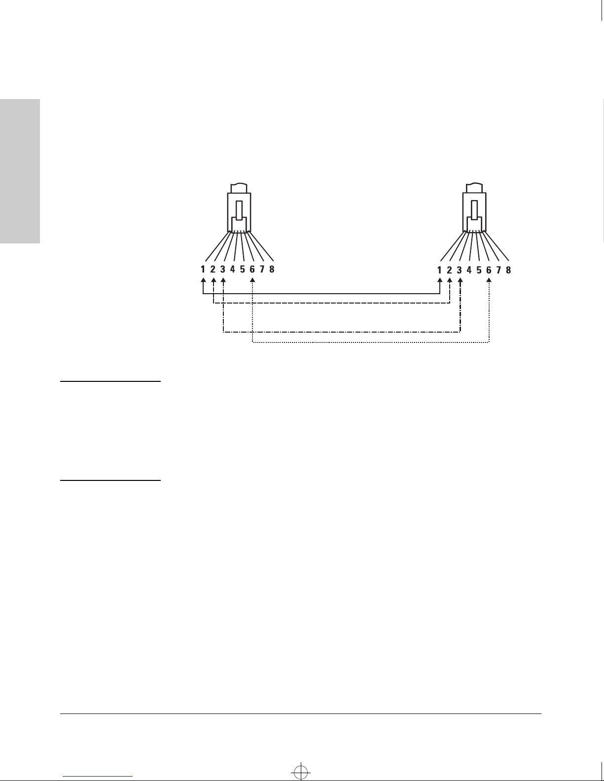
4080~1.boo : 4080_B.FM Page 2 Thursday, July 2, 1998 1:43 PM
Cables and Connectors
Twisted-Pair Cable/Connector Pin-Outs
Twisted-Pair Cable for Switch (MDI-X) to
Computer (MDI) Network Connection
To connect PCs or other MDI network devices to these ports, use a “straightthrough” cable.
Connector “A” Connector “B”
Cables and Connectors
Note
.
Straight-Through Cable
white/orange
orange/white
white/green
green/white
Pins 1 and 2 on connector “A” must be wired as a twisted pair to pins 1 and 2
on connector “B”.
Pins 3 and 6 on connector “A” must be wired as a twisted pair to pins 3 and 6
on connector “B”.
Pins 4, 5, 7, and 8 are not used in this application, although they may be wired
in the cable.
B-2
Page 53
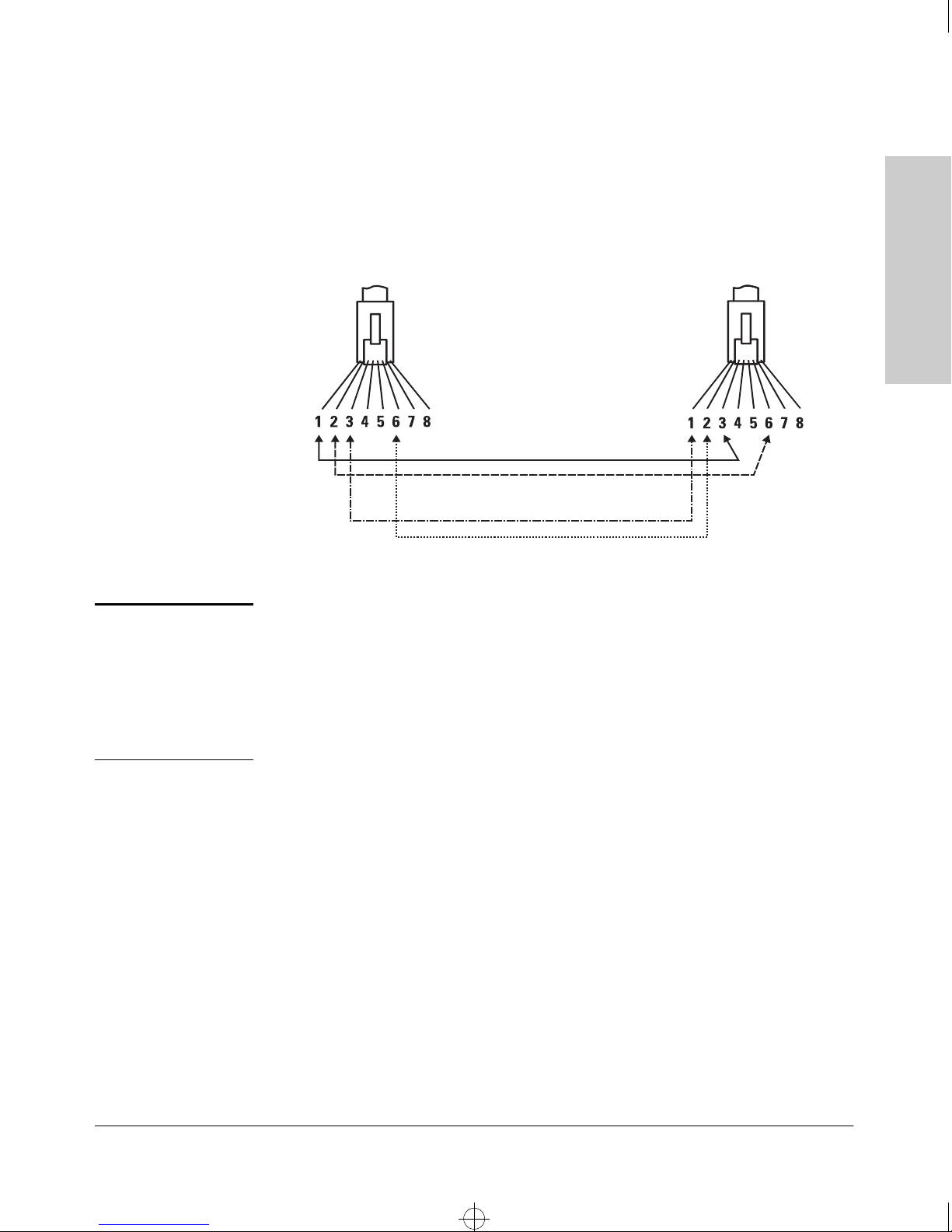
4080~1.boo : 4080_B.FM Page 3 Thursday, July 2, 1998 1:43 PM
Twisted-Pair Cable for Switch (MDI-X) to
Hub or Switch (MDI-X) Network Connection
To connect hubs or switches or other MDI-X network devices to these ports,
use a “crossover” cable.
Cables and Connectors
Twisted-Pair Cable/Connector Pin-Outs
Cables and Connectors
Note
.
Connector “A”
Crossover Cable
Connector “B”
white/orange
orange/white
white/green
green/white
Pins 1 and 2 on connector “A” must be wired as a twisted pair to pins 3 and 6
on connector “B”.
Pins 3 and 6 on connector “A” must be wired as a twisted pair to pins 1 and 2
on connector “B”.
Pins 4, 5, 7, and 8 are not used in this application, although they may be wired
in the cable.
B-3
Page 54
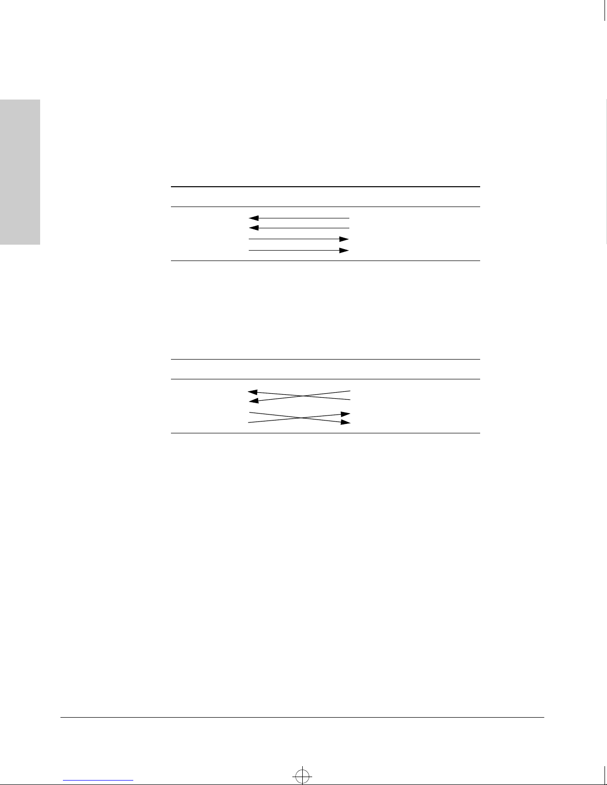
4080~1.boo : 4080_B.FM Page 4 Thursday, July 2, 1998 1:43 PM
Cables and Connectors
Twisted-Pair Cable/Connector Pin-Outs
Twisted-Pair Cable Pin Assignments
Twisted-Pair Straight-Through Cable
Switch End (MDI-X) Computer, Transceiver, or
Other MDI Port End
Signal Pins Pins Signal
Cables and Connectors
receive +
receive transmit +
transmit -
Twisted-Pair Cross-Over Cable
Switch End (MDI-X) Hub or Switch Port, or Other
Signal Pins Pins Signal
receive +
receive transmit +
transmit -
1
2
3
6
1
2
3
6
transmit +
transmit receive +
receive -
MDI-X Port End
1
2
3
6
6
3
2
1
transmit transmit +
receive receive +
B-4
Page 55

4080~1.boo : 4080_B.FM Page 5 Thursday, July 2, 1998 1:43 PM
Cables and Connectors
Fiber-Optic Cables
Fiber-Optic Cables
10Base-FL Ports
Fiber-optic cables connected to the 10Base-FL Switch Module ports must be
850 nm wavelength, multimode cable conforming to the ISO/IEC 793-2 type
B1, and ITU-T G.652 standards, and the cables must have ST-type connectors.
100Base-FX Ports
Fiber-optic cables connected to the 100Base-FX Switch Module ports must be
1300 nm wavelength, multimode cable conforming to the ISO/IEC 793-2 type
B1, and ITU-T G.652 standards, and the cables must have SC-type connectors.
Gigabit-SX Ports
Fiber-optic cables connected to the Gigabit-SX Switch Module ports must be
850 nm wavelength, multimode cable that are fitted with SC-type connectors.
Cables and Connectors
B-5
Page 56

4080~1.boo : 4080_B.FM Page 6 Thursday, July 2, 1998 1:43 PM
Page 57

4080~1.boo : 4080_C.FM Page 1 Thursday, July 2, 1998 1:43 PM
Safety and EMC Regulatory Statements
Safety Information
Documentation reference symbol. If the product is marked with this
!
WARNING A WARNING in the manual denotes a hazard that can cause injury
symbol, refer to the product documentation to get more information
about the product.
or death.
C
Safety and EMC Regulatory
Statements
CAUTION A CAUTION in the manual denotes a hazard that can damage
equipment.
Do not proceed beyond a WARNING or CAUTION notice until you
have understood the hazardous conditions and have taken appropriate steps.
Grounding
These are safety class I products and have protective earthing terminals. There
must be an uninterruptible safety earth ground from the main power source
to the product's input wiring terminals, power cord, or supplied power cord
set. Whenever it is likely that the protection has been impaired, disconnect
the power cord until the ground has been restored.
For LAN cable grounding:
■ If your LAN covers an area served by more than one power distribu-
tion system, be sure their safety grounds are securely interconnected.
■ LAN cables may occasionally be subject to hazardous transient volt-
ages (such as lightning or disturbances in the electrical utilities power
grid). Handle exposed metal components of the network with caution.
Servicing
There are no user-serviceable parts inside these products. Any servicing,
adjustment, maintenance, or repair must be performed only by service-trained
personnel.
These products do not have a power switch; they are powered on when the
power cord is plugged in.
C-1
Page 58

4080~1.boo : 4080_C.FM Page 2 Thursday, July 2, 1998 1:43 PM
Safety and EMC Regulatory Statements
Informations concernant la sécurité
Informations concernant la sécurité
Symbole de référence à la documentation. Si le produit est marqué de
!
WARNING Dans la documentation, un WARNING indique un danger susceptible
CAUTION Un texte de mise en garde intitulé CAUTION indique un danger suscep-
ce symbole, reportez-vous à la documentation du produit afin d'obtenir
des informations plus détaillées.
d'entraîner des dommages corporels ou la mort.
tible de causer des dommages à l'équipement.
Ne continuez pas au-delà d'une rubrique WARNING ou CAUTION avant
d'avoir bien compris les conditions présentant un danger et pris les
mesures appropriées.
Statements
Safety and EMC Regulatory
Cet appareil est un produit de classe I et possède une borne de mise à la terre. La source
d'alimentation principale doit être munie d'une prise de terre de sécurité installée aux
bornes du câblage d'entrée, sur le cordon d'alimentation ou le cordon de raccordement
fourni avec le produit. Lorsque cette protection semble avoir été endommagée,
débrancher le cordon d'alimentation jusqu'à ce que la mise à la terre ait été réparée.
Mise à la terre du câble de réseau local:
■
si votre réseau local s'étend sur une zone desservie par plus d'un système de
distribution de puissance, assurez-vous que les prises de terre de sécurité
soient convenablement interconnectées.
■
Les câbles de réseaux locaux peuvent occasionnellement être soumis à des
surtensions transitoires dangereuses (telles que la foudre ou des perturbations dans le réseau d'alimentation public). Manipulez les composants
métalliques du réseau avec précautions.
Aucune pièce contenue à l'intérieur de ce produit ne peut être réparée par l'utilisateur.
Tout dépannage, réglage, entretien ou réparation devra être confié exclusivement à un
personnel qualifié.
Cet appareil ne comporte pas de commutateur principal ; la mise sous tension est
effectuée par branchement du cordon d'alimentation.
C-2
Page 59

4080~1.boo : 4080_C.FM Page 3 Thursday, July 2, 1998 1:43 PM
Safety and EMC Regulatory Statements
Hinweise zur Sicherheit
Symbol für Dokumentationsverweis. Wenn das Produkt mit diesem
!
WARNING Symbol für Dokumentationsverweis. Wenn das Produkt mit diesem
Symbol markiert ist, schlagen Sie bitte in der Produktdokumentation
nach, um mehr Informationen über das Produkt zu erhalten.
Symbol markiert ist, schlagen Sie bitte in der Produktdokumentation
nach, um mehr Informationen über das Produkt zu erhalten.
Hinweise zur Sicherheit
CAUTION Symbol für Dokumentationsverweis. Wenn das Produkt mit diesem
Symbol markiert ist, schlagen Sie bitte in der Produktdokumentation
nach, um mehr Informationen über das Produkt zu erhalten.
Fahren Sie nach dem Hinweis WARNING oder CAUTION erst fort,
nachdem Sie den Gefahrenzustand verstanden und die entsprechenden Maßnahmen ergriffen haben.
Dies ist ein Gerät der Sicherheitsklasse I und verfügt über einen schützenden Erdungsterminal. Der Betrieb des Geräts erfordert eine ununterbrochene Sicherheitserdung
von der Hauptstromquelle zu den Geräteingabeterminals, den Netzkabeln oder dem
mit Strom belieferten Netzkabelsatz voraus. Sobald Grund zur Annahme besteht, daß
der Schutz beeinträchtigt worden ist, das Netzkabel aus der Wandsteckdose herausziehen, bis die Erdung wiederhergestellt ist.
Für LAN-Kabelerdung:
■
Wenn Ihr LAN ein Gebiet umfaßt, das von mehr als einem Stromverteilungssystem beliefert wird, müssen Sie sich vergewissern, daß die
Sicherheitserdungen fest untereinander verbunden sind.
■
LAN-Kabel können gelegentlich gefährlichen Übergangsspannungen ausgesetzt werden (beispielsweise durch Blitz oder Störungen in dem
Starkstromnetz des Elektrizitätswerks). Bei der Handhabung exponierter
Metallbestandteile des Netzwerkes Vorsicht walten lassen.
Dieses Gerät enthält innen keine durch den Benutzer zu wartenden Teile. Wartungs-,
Anpassungs-, Instandhaltungs- oder Reparaturarbeiten dürfen nur von geschultem
Bedienungspersonal durchgeführt werden.
Safety and EMC Regulatory
Statements
Dieses Gerät hat keinen Netzschalter; es wird beim Anschließen des Netzkabels
eingeschaltet.
C-3
Page 60

4080~1.boo : 4080_C.FM Page 4 Thursday, July 2, 1998 1:43 PM
Safety and EMC Regulatory Statements
Considerazioni sulla sicurezza
Considerazioni sulla sicurezza
Simbolo di riferimento alla documentazione. Se il prodotto è contras-
!
WARNING La dicitura WARNINGdenota un pericolo che può causare lesioni o
CAUTION La dicituraCAUTION denota un pericolo che può danneggiare le
segnato da questo simbolo, fare riferimento alla documentazione sul
prodotto per ulteriori informazioni su di esso.
morte.
attrezzature.
Non procedere oltre un avviso di WARNING o di CAUTIONprima di
aver compreso le condizioni di rischio e aver provveduto alle misure
del caso.
Statements
Safety and EMC Regulatory
Questo prodotto è omologato nella classe di sicurezza I ed ha un terminale protettivo
di collegamento a terra. Dev'essere installato un collegamento a terra di sicurezza, non
interrompibile che vada dalla fonte d'alimentazione principale ai terminali d'entrata,
al cavo d'alimentazione oppure al set cavo d'alimentazione fornito con il prodotto.
Ogniqualvolta vi sia probabilità di danneggiamento della protezione, disinserite il cavo
d'alimentazione fino a quando il collegaento a terra non sia stato ripristinato.
Per la messa a terra dei cavi LAN:
■
se la vostra LAN copre un'area servita da più di un sistema di distribuzione
elettrica, accertatevi che i collegamenti a terra di sicurezza siano ben collegati
fra loro;
■
i cavi LAN possono occasionalmente andare soggetti a pericolose tensioni
transitorie (ad esempio, provocate da lampi o disturbi nella griglia d'alimentazione della società elettrica); siate cauti nel toccare parti esposte in metallo
della rete.
Nessun componente di questo prodotto può essere riparato dall'utente. Qualsiasi
lavoro di riparazione, messa a punto, manutenzione o assistenza va effettuato esclusivamente da personale specializzato.
Questo apparato non possiede un commutatore principale; si mette scotto tensione
all'inserirsi il cavo d'alimentazione.
C-4
Page 61

4080~1.boo : 4080_C.FM Page 5 Thursday, July 2, 1998 1:43 PM
Safety and EMC Regulatory Statements
Consideraciones sobre seguridad
Símbolo de referencia a la documentación. Si el producto va
!
WARNING Una WARNING en la documentación señala un riesgo que podría
CAUTION Una CAUTION en la documentación señala un riesgo que podría
marcado con este símbolo, consultar la documentación del
producto a fin de obtener mayor información sobre el producto.
resultar en lesiones o la muerte.
resultar en averías al equipo.
No proseguir después de un símbolo de WARNING o CAUTION hasta
no haber entendido las condiciones peligrosas y haber tomado las
medidas apropiadas.
Consideraciones sobre seguridad
Safety and EMC Regulatory
Statements
Este aparato se enmarca dentro de la clase I de seguridad y se encuentra protegido por
una borna de puesta a tierra. Es preciso que exista una puesta a tierra continua desde
la toma de alimentación eléctrica hasta las bornas de los cables de entrada del aparato,
el cable de alimentación o el juego de cable de alimentación suministrado. Si existe la
probabilidad de que la protección a tierra haya sufrido desperfectos, desenchufar el
cable de alimentación hasta haberse subsanado el problema.
Puesta a tierra del cable de la red local (LAN):
■
Si la LAN abarca un área cuyo suministro eléctrico proviene de más de una
red de distribución de electricidad, cerciorarse de que las puestas a tierra
estén conectadas entre sí de modo seguro.
■
Es posible que los cables de la LAN se vean sometidos de vez en cuando a
voltajes momentáneos que entrañen peligro (rayos o alteraciones en la red
de energía eléctrica). Manejar con precaución los componentes de metal de
la LAN que estén al descubierto.
Este aparato no contiene pieza alguna susceptible de reparación por parte del usuario.
Todas las reparaciones, ajustes o servicio de mantenimiento debe realizarlos solamente el técnico.
Este producto no tiene interruptor de potencia; se activa cuando se enchufa el cable
de alimentación.
C-5
Page 62
4080~1.boo : 4080_C.FM Page 6 Thursday, July 2, 1998 1:43 PM
Safety and EMC Regulatory Statements
Safety Information (Japan)
Safety Information (Japan)
Statements
Safety and EMC Regulatory
C-6
Page 63
4080~1.boo : 4080_C.FM Page 7 Thursday, July 2, 1998 1:43 PM
Safety and EMC Regulatory Statements
Safety Information (China)
Safety Information (China)
Safety and EMC Regulatory
Statements
C-7
Page 64
4080~1.boo : 4080_C.FM Page 8 Thursday, July 2, 1998 1:43 PM
Safety and EMC Regulatory Statements
EMC Regulatory Statements
EMC Regulatory Statements
U.S.A.
FCC Class A
This equipment has been tested and found to comply with the limits for a Class
A digital device, pursuant to Part 15 of the FCC Rules. These limits are
designed to provide reasonable protection against interference when the
equipment is operated in a commercial environment. This equipment generates, uses, and can radiate radio frequency energy and, if not installed and
used in accordance with the instruction manual, may cause interference to
radio communications. Operation of this equipment in a residential area may
cause interference in which case the user will be required to correct the
interference at his own expense.
Statements
Safety and EMC Regulatory
Canada
This product complies with Class A Canadian EMC requirements.
Australia/New Zealand
This product complies with Australia/New Zealand EMC Class A
requirements.
Japan
VCCI Class A
C-8
Page 65
4080~1.boo : 4080_C.FM Page 9 Thursday, July 2, 1998 1:43 PM
Safety and EMC Regulatory Statements
Korea
Taiwan
EMC Regulatory Statements
Safety and EMC Regulatory
Statements
C-9
Page 66
4080~1.boo : 4080_C.FM Page 10 Thursday, July 2, 1998 1:43 PM
Safety and EMC Regulatory Statements
EMC Regulatory Statements
European Community
Statements
Safety and EMC Regulatory
C-10
Page 67

4080~1.boo : 4080IX.FM Page 1 Thursday, July 2, 1998 1:43 PM
Index
Numerics
100 LED … 1-4
100Base-FX
connections, length limitations … 2-4
ports, cables used with … 2-4, B-5
100Base-TX
connections, length limitations … 2-4
ports, cables used with … 2-4
10Base-FL
connections, length limitations … 2-4
ports, cables used with … 2-4, B-5
10Base-T
connections, length limitations … 2-4
ports, cables used with … 2-4
A
Act LED … 1-4
address learning … 1-10
address table
automatic address learning … 1-10
filtering out traffic … 1-10
flooding traffic … 1-10
forwarding traffic … 1-10
moves and changes … 1-11
operation … 1-10
B
back of switch
description … 1-8
power connector … 1-8
slot for redundant power supply … 1-8
bandwidth, how switch enhances … 1-11
Bootp
for in-band console access … 2-15
buttons
Clear button … 1-7
Mode Select button … 1-6
Reset button … 1-7
C
cabinet
mounting the switch in … 2-10
cables
100Base-FX
connections … 2-4
fiber-optic cable specifications … B-5
100Base-TX connections … 2-4
10Base-FL
connections … 2-4
fiber-optic cable specifications … B-5
10Base-T connections … 2-4
connecting cables to switch ports … 2-14
effects of non-standard cables … 3-2
fiber-optic, specifications … B-5
Gigabit-SX
connections … 2-4
fiber-optic cable specifications … B-5
incorrect network connections … 3-2
infrastructure requirements … 2-4
length limitations … 2-4
required types … 2-4
serial for direct console connection … 2-16
twisted-pair connector pin-outs … B-1
cables, twisted pair
category 3, 4, 5 … B-1
cross-over cable pin-out … B-4
MDI-X to MDI connections … B-2
MDI-X to MDI-X connections … B-3
pin-outs … B-4
straight-through cable pin-out … B-4
switch-to-computer connection … B-2
switch-to-switch or hub connection … B-3
cabling infrastructure … 2-4
Clear button
deleting passwords … 1-7
description … 1-7
location on switch … 1-3, 1-7
restoring factory default configuration … 1-7,
3-10
configuration
restoring factory defaults … 1-7, 3-10
connecting the switch to a power source … 2-14
Index
Index – 1
Page 68

4080~1.boo : 4080IX.FM Page 2 Thursday, July 2, 1998 1:43 PM
Index
connector specifications … A-2
console
checking messages during
troubleshooting … 3-8
displaying Main menu … 2-16
features … 2-15
how to connect in-band … 2-15
how to connect out-of-band … 2-15
serial cable connection … 2-16
telnet access … 2-16
terminal configuration … 2-15
console port
description … 1-6
location on switch … 1-3
cross-over cable
pin-out … B-4
D
deleting passwords … 1-7
description
back of switches … 1-8
front of switches … 1-3
LEDs … 1-4
DHCP
for in-band console access … 2-15
diagnostic tests … 3-8
checking the console messages … 3-8
checking the LEDs … 3-4, 3-8
end-to-end connectivity … 3-10
testing the switch only … 3-8
testing twisted-pair cabling … 3-9
E
electrical specifications, switch … A-1
EMC regulatory statements … C-8
environmental specifications, switch … A-1
Fault LED
behavior during self test … 2-9
description … 1-4
flashing definition … 1-4
location on switch … 1-3
showing error conditions … 3-4
Fdx LED … 1-4
features
console … 2-15
Switch 4000M and 8000M … 1-9
fiber-optic cables … B-5
filtering out traffic … 1-10
flashing LEDs
error indications … 3-4
flooding traffic … 1-10
forwarding traffic … 1-10
front of switch
Clear button … 1-7
console port … 1-6
description … 1-3
LEDs … 1-4
Mode Select button and indicator LEDs … 1-6
Reset button … 1-7
G
Gigabit-SX
connections, length limitations … 2-4
ports, cables used with … 2-4, B-5
H
horizontal surface, mounting switch on … 2-12
hot swapping
redundant power supply … 1-8, 2-6
resetting the switch for new module type … 2-17
switch modules … 2-17
F
factory default configuration, restoring … 1-7, 3-10
Fan Status LED … 1-5
showing error conditions … 3-4
2 – Index
I
in-band console access
types of … 2-15
included parts … 2-1
incorrect network connections … 3-2
Page 69

4080~1.boo : 4080IX.FM Page 3 Thursday, July 2, 1998 1:43 PM
installation
connecting the switch to a power source … 2-14
horizontal surface mounting … 2-12
network cable requirements … 2-4
optional modules … 2-5
precautions … 2-3
rack or cabinet mounting … 2-10
redundant power supply … 2-6
site preparation … 2-4
summary of steps … 2-2
Switch 4000M and 8000M … 2-1
wall mounting … 2-13
L
LEDs
100…1-4
Act … 1-4
behavior during self test … 2-9
checking during troubleshooting … 3-8
descriptions of … 1-4
error indications … 3-4
Fan Status … 1-5
showing error conditions … 3-4
Fault … 1-4
behavior during self test … 2-9
showing error conditions … 3-4
Fdx … 1-4
flashing definition … 1-4–1-5
Link … 1-5
Mode
description … 1-5
selecting the display … 1-6
mode select indicators … 1-4
Module Status … 1-5
showing error conditions … 3-4
on switch chassis … 1-4
on Switch Engine Module … 1-4
on switch modules … 1-5
Power … 1-4
behavior during error conditions … 3-4
behavior during self test … 2-9
Power Status … 1-5
behavior during self test … 2-9
showing error conditions … 3-4
Self Test … 1-4
behavior during self test … 2-9
showing error conditions … 3-4
Switch Engine Fail … 1-4
behavior during self test … 2-9
showing error conditions … 3-4
length limitations
100Base-FX connections … 2-4
100Base-TX connections … 2-4
10Base-FL connections … 2-4
10Base-T connections … 2-4
Gigabit-SX connections … 2-4
Link LEDs … 1-5
link test … 3-9
M
Main menu, console
displaying … 2-16
MDI-X to MDI network cable … B-2
MDI-X to MDI-X network cable … B-3
Mode LEDs
description … 1-5
selecting the display … 1-6
Mode Select
button … 1-6
indicator LEDs … 1-4, 1-6
module slots
location on switch … 1-3
Module Status LEDs … 1-5
showing error conditions … 3-4
modules
Switch Engine Module, LEDs … 1-4
switch modules
hot swapping … 2-17
installing … 2-5
LEDs … 1-5
list of available types … 1-9
mounting the switch
in a rack or cabinet … 2-10
precautions … 2-3
on a horizontal surface … 2-12
on a wall … 2-13
precautions … 2-13
moves and changes
effect on address table … 1-11
Index
Index – 3
Page 70

4080~1.boo : 4080IX.FM Page 4 Thursday, July 2, 1998 1:43 PM
Index
N
network cables
100Base-FX connections … 2-4
100Base-TX connections … 2-4
10Base-FL connections … 2-4
10Base-T connections … 2-4
fiber-optic, specifications … B-5
Gigabit-SX connections … 2-4
incorrect connections … 3-2
required types … 2-4
twisted-pair connector pin-outs … B-1
network devices
connecting to the switch … 2-14
network ports
connecting to … 2-14
LEDs for … 1-5
standards compliance … A-2
types of … 2-4
non-standard network cables, effects … 3-2
O
out-of-band console access … 2-15
P
parts included with the switch … 2-1
passwords, deleting … 1-7
physical specifications, switch … A-1
Ping test … 3-9
pin-outs
twisted-pair cables … B-1
port LEDs
Link … 1-5
Mode…1-5
ports
console … 2-15
network connections … 2-14
power connector … 1-8
Power LED
behavior during error conditions … 3-4
behavior during self test … 2-9
description … 1-4
location on switch … 1-3
Power Status LEDs … 1-5
behavior during self test … 2-9
showing error conditions … 3-4
power supply
connecting to a power source … 2-14
installation cautions … 1-8, 2-6
making redundant power connections … 2-14
precautions
installing power supply … 1-8, 2-6
mounting the switch in a rack or cabinet … 2-3
mounting the switch on a wall … 2-13
power requirements … 2-3
preparing the installation site … 2-4
Proactive Network tools
diagnostics with … 3-7
R
rack
mounting the switch in … 2-10
rebooting the switch
to initialize new module type … 2-5
redundant power connections … 2-14
redundant power supply
installation cautions … 1-8, 2-6
installing … 2-6
slot for installing … 1-8
regulatory statements … C-8
Reset button
description … 1-7
location on switch … 1-3, 1-7
restoring factory default configuration … 3-10
resetting the switch
factory default reset … 3-10
for module hot swap … 2-17
location of Reset button … 1-7
troubleshooting procedure … 3-8
S
safety and regulatory statements … C-1
safety specifications … A-2
selecting the Mode LED display … 1-6
self test
Fault LED behavior … 2-9
LED behavior during … 2-9
Power LED behavior … 2-9
Self Test LED behavior … 2-9
Switch Engine Fail LED behavior … 2-9
4 – Index
Page 71

4080~1.boo : 4080IX.FM Page 5 Thursday, July 2, 1998 1:43 PM
Self Test LED
behavior during factory default reset … 3-10
behavior during self test … 2-9
description … 1-4
showing error conditions … 3-4
serial cable
for direct console connection … 2-16
slots for modules
location on switch … 1-3
specifications
connectors … A-2
electrical … A-1
environmental … A-1
physical … A-1
safety … A-2
straight-through cable
pin-out … B-4
summary
of cables used with the switch … 2-4
of switch installation … 2-2
switch
connecting to a power source … 2-14
description … 1-1
electrical specifications … A-1
environmental specifications … A-1
features … 1-9
front panel description … 1-3
included parts … 2-1
mounting in a rack or cabinet … 2-10
mounting on a horizontal surface … 2-12
mounting on a wall … 2-13
operation … 1-10
physical specifications … A-1
switch chassis
LED descriptions … 1-4
Switch Engine Fail LED
behavior during self test … 2-9
description … 1-4
showing error conditions … 3-4
Switch Engine Module
LEDs descriptions … 1-4
switch modules
booting the switch to initialize new module
type … 2-5
hot swapping … 2-17
installing … 2-5
LEDs descriptions … 1-5
list of available types … 1-9
switch operation
address table … 1-10
description … 1-10
effect of VLANs … 1-11
filtering out traffic … 1-10
flooding traffic … 1-10
forwarding traffic … 1-10
network moves and changes … 1-11
simultaneous network communications … 1-11
verifying after installation … 2-8
T
telnet access to the console … 2-16
terminal configuration … 2-15
testing
checking the console messages … 3-8
checking the LEDs … 3-8
diagnostic tests … 3-8
end-to-end communications … 3-10
link test … 3-9
Ping test … 3-9
switch operation … 3-8
switch-to-device communications … 3-9
twisted-pair cabling … 3-9
tips for troubleshooting … 3-2
topologies
effects of improper topology … 3-2
troubleshooting … 3-1
basic tips … 3-2
checking the console messages … 3-8
checking the LEDs … 3-8
common network problems … 3-2
diagnostic tests … 3-8
effects of improper topology … 3-2
effects of non-standard cables … 3-2
incorrect network connections … 3-2
link test … 3-9
Ping test … 3-9
Proactive Network tools … 3-7
restoring factory default configuration … 3-10
testing connections to other devices … 3-9
testing end-to-end communications … 3-10
testing the switch … 3-8
testing the twisted-pair cables … 3-9
Index
Index – 5
Page 72

4080~1.boo : 4080IX.FM Page 6 Thursday, July 2, 1998 1:43 PM
twisted-pair cable
cross-over cable pin-out … B-4
pin-outs … B-1, B-4
straight-through cable pin-out … B-4
switch-to-computer connection … B-2
switch-to-switch or hub connection … B-3
testing … 3-9
V
VLAN
effect on basic switch operation … 1-11
VT-100 terminal
serial cable connection for … 2-16
Index
W
wall
mounting switch on … 2-13
6 – Index
 Loading...