

HP ProCurve 6120XG Installation Instructions Manual
HP ProCurve
g
Overview
6120G/XG Blade Switch
Installation Instructions
for HP c-Class BladeSystem
This card provides instructions for installing an HP ProCurve
6120G/XG Blade Switch for c-Class BladeSystem in an HP c-Class
BladeSystem enclosure.
Kit contents
HP ProCurve 6120G/XG Blade Switch
Console cable (USB A to USB mini-AB)
Customer Support/Warranty booklet
License documentation
This document
IMPORTANT: Only use HP-approved pluggable SFP or XFP
optical transceiver modules. For more information, see the
QuickSpecs on the HP website
(http://www.hp.com/go/bladesystem/interconnects).
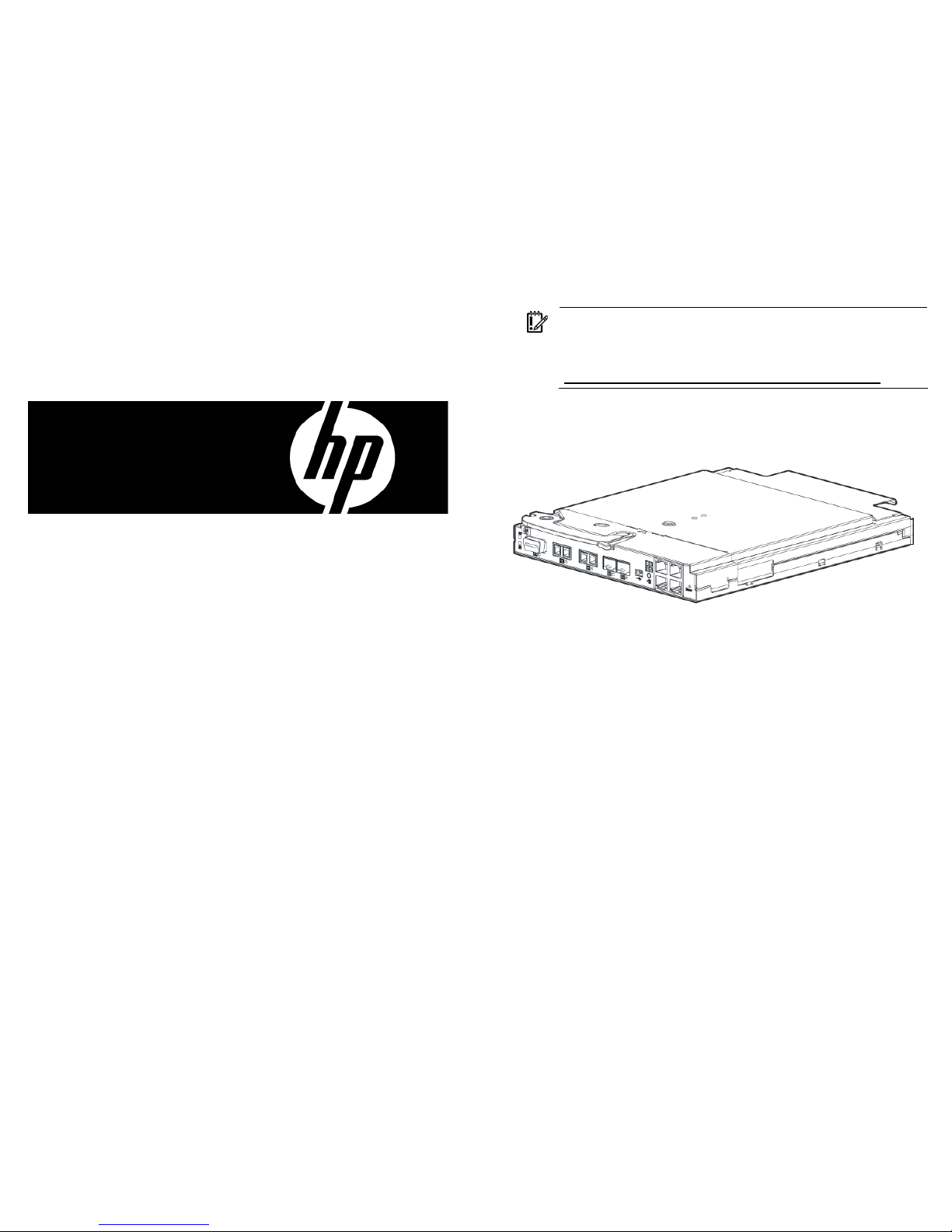
HP ProCurve 6120G/XG Blade Switch
© Copyright 2009 Hewlett-Packard Development Company, L.P.
The information contained herein is subject to change without notice. The
only warranties for HP products and services are set forth in the express
warranty statements accompanying such products and services. Nothing
herein should be construed as constituting an additional warranty. HP shall
not be liable for technical or editorial errors or omissions contained herein.
Microsoft is a U.S. re
Part Number 532189-001
March 2009 (First Edition)
istered trademark of Microsoft Corporation.
Additional information
For more information on the association between the server blade
mezzanine connectors and the interconnect bays, see the HP
BladeSystem enclosure setup and installation guide that ships with
the enclosure. During server blade installation, the location of the
mezzanine card determines the installation location of the switch
modules.
For specific switch port connection information for each blade, see
the HP BladeSystem enclosure setup and installation guide that ships
with the enclosure. Connections differ by blade type.
Installation guidelines
Observe the following guidelines:
All HP ProCurve switches in the enclosure require valid and
unique IP addresses before they can be accessed via Ethernet.
By default DHCP is enabled on these switches, so the switch
management interface can get IP credentials from the DHCP
server on the attached Ethernet network. If EBIPA is enabled on
the Onboard Administrator (OA) of the enclosure, OA will
assign an IP address to the switch from its configured IP
address range, so that switch can be accessed from the OA
Ethernet interface. If EBIPA is disabled but DHCP service is
available on the network attached to the OA Ethernet interface,
then the switch gets its IP address assigned from the attached
network. Any IP host on that network can access the switch at
this point. If the DHCP service is not available on the attached
network, the user can assign valid IP credentials from the

switch CLI, accessing it via serial interface attached to OA
and/or USB interface attached to the blade.
When using optional transceiver modules or direct-attach
cables, order the modules and cables separately. For more
information, see the QuickSpecs on the HP website
(http://www.hp.com/go/bladesystem/interconnects
).
For more information on BladeSystem port mapping, see the
HP BladeSystem enclosure setup and installation guide that
shipped with the enclosure.
For the most current product information, see the release notes
at http://www.hp.com/go/bladesystem/documentation
LEDs
Item LED description Status
1 Module locator
(UID)
Blue = Module ID selected
Off = Module ID not selected
Firmware requirements
Always install the most current firmware or software for the following
items:
Server blade system ROMs
Ethernet mezzanines
HP BladeSystem Onboard Administrator
HP ProCurve blade switch
For additional information on required firmware or software versions
and to download firmware or software updates, see the HP website:
1. Go to http://www.hp.com/#Support.
2. Cli
ck the “Download drivers and software” radio button.
3. Enter “6120G/XG” in the text box and click “Go”.
4. Click the link for your operating system.
5. Download the appropriate software or firmware.
Front Panel
Item Description
1 Port C1 (10GBASE-CX4)
2 Port X1 XFP (10-GbE) slot*
3 Port X2 XFP (10-GbE) slot*
4 Port S1 SFP (1-GbE) slot**
5 Port S2 SFP (1-GbE) slot**
6 Console port (USB 2.0 mini-AB connector)
7 Clear button
8 Ports 1–4 (10/100/1000BASE-T)
9 Reset button (recessed)
* Supports 10GBASE-SR XFP and 10GBASE-LR XFP pluggable
optical transceiver modules
** Supports 1000BASE-T SFP, 1000BASE-SX SFP, and 1000BASELX SFP pluggable optical transceiver modules
2 Module status
(health)
Green = Normal operation
Amber = Fault
Off = Power off
3 C1 port status
(10GBASE-CX4)
Green = Port is connected to the
network.
Amber = Fault
Off = Not connected
4 C1 activity Green flashing = Activity
5 Port X1/X2 status
(XFP connector)
Green = Port is connected to the
network.
Amber = Fault
Off = Not connected
6 Port X1/X2
Green flashing = Activity
activity
7 Port S1/S2 status
(SFP connector)
Green = Port is connected to the
network.
Amber = Fault
Off = Not connected
8 Port S1/S2
Green flashing = Activity
activity
9 Port 1–4 port
status
Green = Port is connected to the
network.
Amber = Fault
Off = Not connected
10 Port 1–4
Green flashing = 10/100 activity
link/activity
11 Port 1–4
Amber flashing = 1000 activity
link/activity
 Loading...