

HP ProCurve J8161A, ProCurve 600, J8169A, ProCurve 610, J8168A Installation And Getting Started Manual
Installation and
Getting Started Guide
HP ProCurve
600/610 External
Power Supplies
www.hp.com/go/hpprocurve
PoE
Power over Ethernet Devices


HP ProCurve 600/610
External Power Supplies
Installation and Getting Started Guide

© Copyright 2004 Hewlett-Packard Development Company, L.P. The information contained herein is subject
to change without notice.
This document contains proprietary information, which is
protected by copyright. No part of this document may be
photocopied, reproduced, or translated into another
language without the prior written consent of HewlettPackard.
Publication Number
5990-8800
August 2004
Applicable Products
HP ProCurve 600 Redundant and
External Power Supply (J8168A)
HP ProCurve 610 External Power Supply (J8169A)
Disclaimer
HEWLETT-PACKARD COMPANY MAKES NO WARRANTY
OF ANY KIND WITH REGARD TO THIS MATERIAL,
INCLUDING, BUT NOT LIMITED TO, THE IMPLIED
WARRANTIES OF MERCHANTABILITY AND FITNESS
FOR A PARTICULAR PURPOSE. Hewlett-Packard shall not
be liable for errors contained herein or for incidental or
consequential damages in connection with the furnishing,
performance, or use of this material.
The only warranties for HP products and services are set
forth in the express warranty statements accompanying
such products and services. Nothing herein should be
construed as constituting an additional warranty. HP shall
not be liable for technical or editorial errors or omissions
contained herein.
Hewlett-Packard assumes no responsibility for the use or
reliability of its software on equipment that is not furnished
by Hewlett-Packard.
Warranty
See the Customer Support/Warranty booklet included with
the product.
A copy of the specific warranty terms applicable to your
Hewlett-Packard products and replacement parts can be
obtained from your HP Sales and Service Office or
authorized dealer.
Hewlett-Packard Company
8000 Foothills Boulevard, m/s 5552
Roseville, California 95747-5552
http://www.hp.com/go/hpprocurve
Safety
Before installing and operating these products, please
read the “Installation Precautions” in chapter 2,
“Installing and Connecting the HP 600/610 External
Power Supplies”, and the safety statements in appendix C, “Safety and Regulatory Statements”.

Contents
1 Introducing the HP ProCurve 600/610 External Power
Supplies
Front of the Unit . . . . . . . . . . . . . . . . . . . . . . . . . . . . . . . . . . . . . . . . . . . . . . 1-3
EPS Ports on the HP 610 EPS . . . . . . . . . . . . . . . . . . . . . . . . . . . . . . . . . 1-3
LEDs . . . . . . . . . . . . . . . . . . . . . . . . . . . . . . . . . . . . . . . . . . . . . . . . . . . . . . 1-3
Back of the Unit . . . . . . . . . . . . . . . . . . . . . . . . . . . . . . . . . . . . . . . . . . . . . . . 1-6
RPS Ports on the HP 600 RPS/EPS . . . . . . . . . . . . . . . . . . . . . . . . . . . . . 1-6
EPS Ports on the HP 600 RPS/EPS . . . . . . . . . . . . . . . . . . . . . . . . . . . . . 1-6
Port Status LEDs . . . . . . . . . . . . . . . . . . . . . . . . . . . . . . . . . . . . . . . . . . . . 1-7
Internal Power Status LED . . . . . . . . . . . . . . . . . . . . . . . . . . . . . . . . . . . 1-7
EPS Backup Power Ports . . . . . . . . . . . . . . . . . . . . . . . . . . . . . . . . . . . . . 1-7
Power Connector . . . . . . . . . . . . . . . . . . . . . . . . . . . . . . . . . . . . . . . . . . . 1-7
RPS Port Operation . . . . . . . . . . . . . . . . . . . . . . . . . . . . . . . . . . . . . . . . . . . 1-8
EPS Port Operation . . . . . . . . . . . . . . . . . . . . . . . . . . . . . . . . . . . . . . . . . . . 1-8
EPS Backup Power Port Operation . . . . . . . . . . . . . . . . . . . . . . . . . . . . . 1-9
Supported Switches . . . . . . . . . . . . . . . . . . . . . . . . . . . . . . . . . . . . . . . . . . 1-10
2 Installing and Connecting the HP 600/610 External Power
Supplies
Included Parts . . . . . . . . . . . . . . . . . . . . . . . . . . . . . . . . . . . . . . . . . . . . . . . . 2-2
Installation Procedures . . . . . . . . . . . . . . . . . . . . . . . . . . . . . . . . . . . . . . . . 2-3
Summary . . . . . . . . . . . . . . . . . . . . . . . . . . . . . . . . . . . . . . . . . . . . . . . . . . . 2-3
Installation Precautions: . . . . . . . . . . . . . . . . . . . . . . . . . . . . . . . . . . . . . . 2-4
1. Prepare the Installation Site . . . . . . . . . . . . . . . . . . . . . . . . . . . . . . . . 2-6
2. Mount the Unit . . . . . . . . . . . . . . . . . . . . . . . . . . . . . . . . . . . . . . . . . . . . 2-6
Rack or Cabinet Mounting . . . . . . . . . . . . . . . . . . . . . . . . . . . . . . . . 2-6
Horizontal Surface Mounting . . . . . . . . . . . . . . . . . . . . . . . . . . . . . . 2-8
3. Connect to Switches . . . . . . . . . . . . . . . . . . . . . . . . . . . . . . . . . . . . . . . 2-9
Connecting RPS Ports to Switches . . . . . . . . . . . . . . . . . . . . . . . . . 2-9
Connecting EPS Ports to Switches . . . . . . . . . . . . . . . . . . . . . . . . 2-10
i

4. HP 610 EPS Only: Connect the EPS Backup Power Ports . . . . . . . 2-11
5. Connect to AC Power . . . . . . . . . . . . . . . . . . . . . . . . . . . . . . . . . . . . . 2-13
6. Verify Correct Operation . . . . . . . . . . . . . . . . . . . . . . . . . . . . . . . . . . 2-14
LED Behavior: . . . . . . . . . . . . . . . . . . . . . . . . . . . . . . . . . . . . . . . . . 2-14
Recommended Connection Topologies . . . . . . . . . . . . . . . . . . . . . . . . . 2-16
RPS Connections on the HP 600 RPS/EPS . . . . . . . . . . . . . . . . . . . . . . 2-16
Recommendations . . . . . . . . . . . . . . . . . . . . . . . . . . . . . . . . . . . . . . 2-16
Limitations . . . . . . . . . . . . . . . . . . . . . . . . . . . . . . . . . . . . . . . . . . . . 2-17
Status Indication . . . . . . . . . . . . . . . . . . . . . . . . . . . . . . . . . . . . . . . 2-17
EPS Connections on the HP 600 RPS/EPS . . . . . . . . . . . . . . . . . . . . . . 2-17
Recommendations . . . . . . . . . . . . . . . . . . . . . . . . . . . . . . . . . . . . . . 2-17
Limitations . . . . . . . . . . . . . . . . . . . . . . . . . . . . . . . . . . . . . . . . . . . . 2-18
EPS Connections on the HP 610 EPS . . . . . . . . . . . . . . . . . . . . . . . . . . 2-19
Recommendations . . . . . . . . . . . . . . . . . . . . . . . . . . . . . . . . . . . . . . 2-19
Limitations . . . . . . . . . . . . . . . . . . . . . . . . . . . . . . . . . . . . . . . . . . . . 2-20
Status Indication . . . . . . . . . . . . . . . . . . . . . . . . . . . . . . . . . . . . . . . 2-20
EPS Backup Power . . . . . . . . . . . . . . . . . . . . . . . . . . . . . . . . . . . . . . . . . 2-21
Recommendations . . . . . . . . . . . . . . . . . . . . . . . . . . . . . . . . . . . . . . 2-23
Limitations (Calculating required number of HP 610 EPS units) 2-23
Status Indication . . . . . . . . . . . . . . . . . . . . . . . . . . . . . . . . . . . . . . . 2-25
Fault Conditions . . . . . . . . . . . . . . . . . . . . . . . . . . . . . . . . . . . . . . . . 2-25
Replacement Procedures . . . . . . . . . . . . . . . . . . . . . . . . . . . . . . . . 2-26
UPS Support . . . . . . . . . . . . . . . . . . . . . . . . . . . . . . . . . . . . . . . . . . . . . . . 2-26
3 Troubleshooting
Basic Troubleshooting Tips . . . . . . . . . . . . . . . . . . . . . . . . . . . . . . . . . . . . 3-1
Diagnosing with the LEDs . . . . . . . . . . . . . . . . . . . . . . . . . . . . . . . . . . . . . 3-2
Diagnostic Tests . . . . . . . . . . . . . . . . . . . . . . . . . . . . . . . . . . . . . . . . . . . . . . 3-5
Testing the Unit by Resetting It . . . . . . . . . . . . . . . . . . . . . . . . . . . . . . . . 3-5
Checking the Unit’s LEDs . . . . . . . . . . . . . . . . . . . . . . . . . . . . . . . . . 3-5
Testing Cabling . . . . . . . . . . . . . . . . . . . . . . . . . . . . . . . . . . . . . . . . . . . . . 3-5
HP Customer Support Services . . . . . . . . . . . . . . . . . . . . . . . . . . . . . . . . . 3-6
ii

A Specifications
Physical . . . . . . . . . . . . . . . . . . . . . . . . . . . . . . . . . . . . . . . . . . . . . . . . . . A-1
Electrical . . . . . . . . . . . . . . . . . . . . . . . . . . . . . . . . . . . . . . . . . . . . . . . . . A-1
Environmental . . . . . . . . . . . . . . . . . . . . . . . . . . . . . . . . . . . . . . . . . . . . A-1
Acoustic . . . . . . . . . . . . . . . . . . . . . . . . . . . . . . . . . . . . . . . . . . . . . . . . . . A-2
Connectors . . . . . . . . . . . . . . . . . . . . . . . . . . . . . . . . . . . . . . . . . . . . . . . . A-2
Safety . . . . . . . . . . . . . . . . . . . . . . . . . . . . . . . . . . . . . . . . . . . . . . . . . . . . A-2
EMC Compliance (Class A) . . . . . . . . . . . . . . . . . . . . . . . . . . . . . . . . . . A-2
Immunity . . . . . . . . . . . . . . . . . . . . . . . . . . . . . . . . . . . . . . . . . . . . . . . . . A-2
B Connectors and Cables
HP 600 RPS/EPS Ports . . . . . . . . . . . . . . . . . . . . . . . . . . . . . . . . . . . . . . B-1
HP 610 EPS Ports . . . . . . . . . . . . . . . . . . . . . . . . . . . . . . . . . . . . . . . . . . B-1
Connector Pin-Outs . . . . . . . . . . . . . . . . . . . . . . . . . . . . . . . . . . . . . . . . . . B-2
EPS Cable for HP PoE Switch Connections . . . . . . . . . . . . . . . . . . . . B-2
Connector Diagram . . . . . . . . . . . . . . . . . . . . . . . . . . . . . . . . . . . . . B-2
Pin Assignments . . . . . . . . . . . . . . . . . . . . . . . . . . . . . . . . . . . . . . . B-2
RPS Cable for HP ProCurve Switch Connections . . . . . . . . . . . . . . . . B-3
Connector Diagram . . . . . . . . . . . . . . . . . . . . . . . . . . . . . . . . . . . . . B-3
Pin Assignments . . . . . . . . . . . . . . . . . . . . . . . . . . . . . . . . . . . . . . . . B-3
EPS Backup Power Cable for HP 610 EPS Connections . . . . . . . . . . B-4
Connector Diagram . . . . . . . . . . . . . . . . . . . . . . . . . . . . . . . . . . . . . B-4
Pin Assignments (10-pin Connector) . . . . . . . . . . . . . . . . . . . . . . B-4
C Safety and EMC Regulatory Statements
Safety Information . . . . . . . . . . . . . . . . . . . . . . . . . . . . . . . . . . . . . . . . . . . C-1
EMC Regulatory Statements . . . . . . . . . . . . . . . . . . . . . . . . . . . . . . . . . . C-8
Index
iii

— This page is intentionally unused. —
Introducing the HP ProCurve 600/610 External
1
Introducing the HP ProCurve 600/
610 External Power Supplies
Power Supplies
The HP ProCurve 600 Redundant and External Power Supply is a dual-mode
power supply that can supply backup power to so equipped HP ProCurve
switches and additional power for Power over Ethernet (PoE) capable
switches.
The HP ProCurve 610 External Power Supply can supply additional power for
PoE capable switches and backup power to other HP ProCurve 610 units.
EPS PortStatus
E1
E2
Device Connected
Power
Fault
Power
Fault
Fan/Temp
Status
Fan/TempStatus flash = Temperature too high
Fan/TempStatus + Fault flash = Fan failure
HP ProCurve
610 EPS
J8169A
Internal Power Status
Fan/Temp Status
Fan/TempStatus flash = Temperature too high
Fan/TempStatus + Fault flash = Fan failure
Power Status
EPS Backup Power Ports Status
Out Ready
In Ready
HP ProCurve 600 Redundant and External Power Supply (J8168A)
Device Connected
Power Status
R6 R5
RPS Port Status
R4 R3
R1
R2
HP ProCurve 610 External Power Supply (J8169A)
EPS Ports PairA
EPS A1
(
408 W total for PoE applications
)
Device
A1
A2
Connected
EPS A2 EPS B1
Power
Status
EPS Ports: 50 V
8.3 A max per port pair.
EPS Ports PairB
(
408 W total for PoE applications
B1
EPS B2
)
Device
B2
Connected
Power
Status
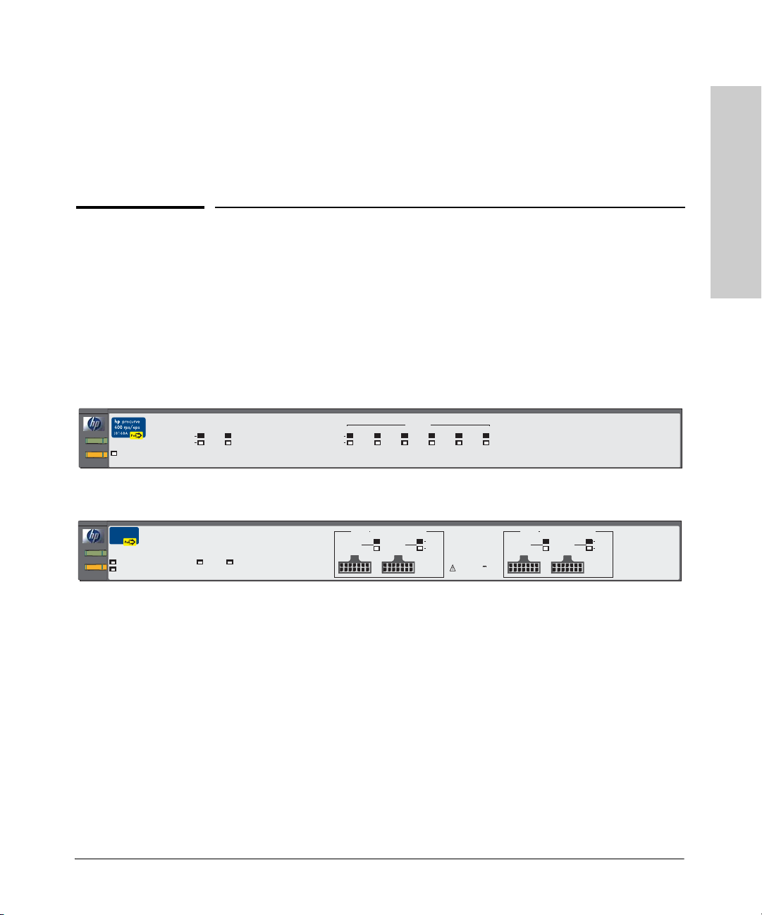
Throughout this manual, these units will be abbreviated as the HP 600 RPS/
EPS and HP 610 EPS.
The HP 600 RPS/EPS has six redundant power supply (RPS) ports supporting
backup power to six supported HP ProCurve switches. The HP 600 RPS/EPS
also has two external power supply (EPS) ports that provide PoE power for
up to two HP PoE switches.
The HP 610 EPS has four EPS ports that provide PoE power for up to four HP
PoE switches. The HP 610 EPS also has two backup ports for supporting
backup power to other HP 610 EPS units connected in a group. There are two
supported topologies, a string (daisy-chain) and a ring (closed-loop).
1-1

Introducing the HP ProCurve 600/610 External Power Supplies
610 External Power Supplies
Introducing the HP ProCurve 600/
This chapter describes your HP 600 RPS/EPS and HP 610 EPS including:
■ front of the unit (page 1-3)
■ back of the unit (page 1-6)
■ RPS port operation (page 1-8)
■ EPS port operation (page 1-8)
■ backup power port operation (page 1-9)
■ supported switches (page 1-10)
1-2
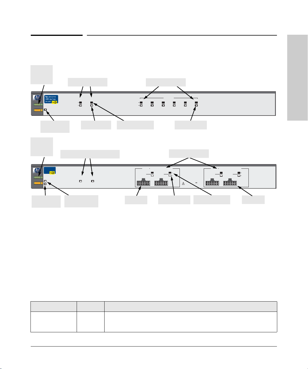
Power
and Fault
LEDs
Front of the Unit
EPS port LEDs
Introducing the HP ProCurve 600/610 External Power Supplies
Front of the Unit
RPS port LEDs
HP 600 RPS/EPS
Introducing the HP ProCurve 600/
610 External Power Supplies
Fan/Temp
Power
Status
Fan/TempStatus flash = Temperature too high
Fault
Fan/TempStatus + Fault flash = Fan failure
Fan/Temp
Status LED
Power
and Fault
LEDs
HP ProCurve
610 EPS
J8169A
Power
Fan/TempStatus flash = Temperature too high
Fault
Fan/TempStatus + Fault flash = Fan failure
Fan/Temp
Status LED
Device Connected
Power Status
EPS Backup Power port LEDs
Internal Power Status
Fan/Temp Status
EPS Backup Power Ports Status
In Ready
Internal Power
Status LED
EPS PortStatus
E1
E2
Power Status
Out Ready
R6 R5
Device Connected
Power Status
Device Connected
EPS Ports PairA
EPS A1
EPS Pair A
RPS Port Status
R4 R3
R1
R2
Power Status
EPS port LEDs
(
408 W total for PoE applications
)
Device
A1
A2
Connected
EPS A2 EPS B1
Power
Status
EPS Ports: 50 V
8.3 A max per port pair.
Power Status
Device Connected
EPS Ports PairB
(
408 W total for PoE applications
B1
EPS B2
HP 610 EPS
)
Device
B2
Connected
Power
Status
EPS Pair B
EPS Ports on the HP 610 EPS
The HP 610 EPS has four external power supply ports. You can connect one
to four HP PoE capable switches to provide PoE power as a primary or backup
source. Power is equally shared between the EPS ports in pair A (that is, port
A1 and A2) and between the EPS ports in pair B (port B1 and B2); one port in
each pair supplies maximum power (408 W) if the other port is not used.
LEDs
Table 1-1. HP 600 RPS/EPS and HP 610 EPS LEDs
LED State Meaning
Power
(green)
On The unit is powered on.
Off The unit is NOT powered on.
1-3

Introducing the HP ProCurve 600/610 External Power Supplies
Front of the Unit
Table 1-1. HP 600 RPS/EPS and HP 610 EPS LEDs (Continued)
LED State Meaning
Fault
(orange)
610 External Power Supplies
Introducing the HP ProCurve 600/
Internal Power
Status (green)
(also on back panel
of the HP 610 EPS)
Fan/Temp Status
(green)
Port Status (also on back panel of the HP 600 RPS/EPS)
Device Connected
(green – over-laid
with the port
number)
Power Status
(green)
Off The normal state; indicates that there are no fault conditions on the unit.
Blinking*†A fault has occurred on the unit, one of the ports, or the fan. The Status LED for the
component with the fault will blink simultaneously.
On On briefly after the unit is powered on or reset, at the beginning of unit self test. If
this LED is on for a prolonged time, the unit has encountered a fatal hardware
failure, or has failed its self test. See chapter 3, “Troubleshooting” for more
information.
On The HP 610 EPS unit’s internal power supply is operating normally.
Blinking* The HP 610 EPS unit’s internal power supply has failed and the unit is being
powered by another HP 610 EPS. The unit Fault LED will be blinking simultaneously.
On The cooling fans are operating normally.
Blinking* One of these conditions exists:
• A cooling fan has failed. The unit Fault LED will be blinking simultaneously.
• There is an over temperature condition in the unit. The unit Fault LED is off.
On There is a valid connection to a device. For xl PoE Modules, the EPS Device
Connected LED is only on if the module is receiving power from the 5300 switch
chassis.
Off There is no device connected to the port.
On The unit is supplying power to a connected device.
Off One of these conditions exists:
• There is no connected device.
• A connected RPS device does not require power.
• A connected EPS device has not successfully communicated for EPS power.
Blinking* One of these conditions exists:
• On the HP 600 RPS/EPS, RPS power is not available to the connected device
because a higher priority port is using it.
• When the LED is blinking simultaneously with the Fault LED, there is a fault
condition on the port.
* The blinking behavior is an on/off cycle once every 1.6 seconds, approximately.
†
Specific fault conditions can be viewed by checking switch log files.
1-4

Introducing the HP ProCurve 600/610 External Power Supplies
Front of the Unit
Table 1-1. HP 600 RPS/EPS and HP 610 EPS LEDs (Continued)
LED State Meaning
EPS Backup Power Status (on front and back panels of the HP 610 EPS only)
In Ready
(green)
Out Ready
(green)
* The blinking behavior is an on/off cycle once every 1.6 seconds, approximately.
On Backup power is available from another HP 610 EPS in the backup power group.
Off Backup power is not available. One of these conditions exists:
• There is not adequate reserve power in the other units to support this device.
• The backup power cable is not properly connected.
• One or more of the backup power cables are faulty.
On Backup power is available for other HP 610 EPS units in the backup power group.
Off Backup power is not available for other HP 610 EPS units. The unit’s internal power
supply has failed and the unit is being powered by another HP 610 EPS. The unit’s
Internal Power Status and Fault LEDs will be blinking simultaneously.
Introducing the HP ProCurve 600/
610 External Power Supplies
1-5
Introducing the HP ProCurve 600/610 External Power Supplies
Back of the Unit
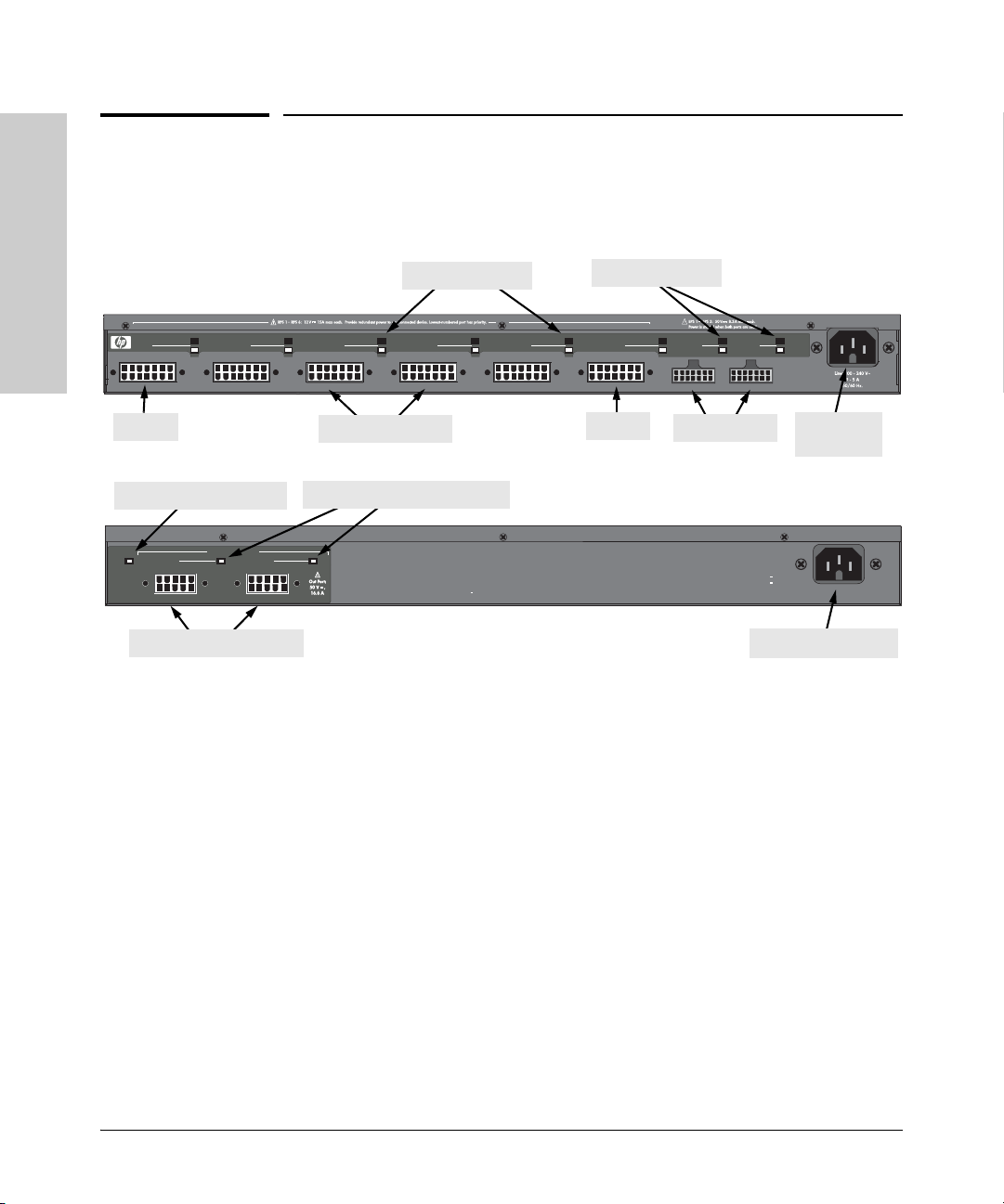
Back of the Unit
Device Connected
RPS 1
610 External Power Supplies
Power Status
Introducing the HP ProCurve 600/
RPS 1
Internal Power Status LED
In
In
Internal
Internal
Power
Power
Status
Status
EPS Backup Power ports
RPS 2
EPS Backup Power Ports
EPS Backup Power Ports
Ready
Ready
RPS port LEDs
EPS port LEDs
HP 600 RPS/EPS
R2
R3R1
RPS 3
R4
RPS 4
RPS ports
R5
RPS 5
RPS 6
R6
RPS 6
E1
EPS 1
EPS ports
EPS Backup Power port LEDs
Ready
Out
Out
Ready
Multiple power sources disconnect both t he AC cord and EPS Bac kup power cables to completely remove power from the unit.
Device
E2
Connected
EPS 2
Power
Status
AC power
connector
HP 610 EPS
Hz
Line: 50/60
240 V~
110
11 6 A
AC power connector
RPS Ports on the HP 600 RPS/EPS
The HP 600 RPS/EPS has six redundant power supply ports. You can connect
up to six HP ProCurve switch units, but backup power can be supplied to only
one unit based on port priority. Port 1 has the highest priority and port 6 the
lowest. A switch connected to port 1 always receives power before any other
port. Likewise, port 2 receives power before ports 3 to 6, port 3 receives power
before ports 4 to 6, and so on down to port 6, which only receives power when
no other port is receiving power.
1-6
EPS Ports on the HP 600 RPS/EPS
The HP 600 RPS/EPS has two external power supply ports. You can connect
one or two HP PoE capable switches to provide PoE power as a primary or
backup source. Power is equally shared between the two EPS ports (204 W
each); one port supplies maximum power (408 W) if the other port is not used.

Introducing the HP ProCurve 600/610 External Power Supplies
Back of the Unit
Port Status LEDs
The RPS and EPS port status LEDs on the HP 600 RPS/EPS back panel are a
duplication of those on the front panel. Similarly, the backup power port status
LEDs on the HP 610 EPS back panel are a duplication of those on the front
panel. For a description of these LEDs, see Table 1-1 on page 1-3.
Internal Power Status LED
The Internal Power Status LED on the HP 610 EPS back panel is a duplication
of the one on the front panel. For a description of this LED, see Table 1-1 on
page 1-3.
EPS Backup Power Ports
The HP 610 EPS has two backup power ports that allow up to five EPS units
to be connected together and thereby provide backup power to a failed unit.
However, note that the power load on the remaining active units must be
limited so that there is still enough reserve power to support a failed unit. The
simplest way is to have one unit in the group that has no direct PoE load on
it. Sample topologies are shown at the end of chapter 2 in this book.
Power Connector
Introducing the HP ProCurve 600/
610 External Power Supplies
The HP 600 RPS/EPS and HP 610 EPS do not have a power switch; they are
powered on when connected to an active AC power source. The HP 600 RPS/
EPS automatically adjusts to any voltage between 100--240 volts and either 50
or 60 Hz, and the HP 610 EPS between 110--240 volts and either 50 or 60 Hz.
There are no voltage range settings required.
In addition, the HP 610 EPS may be powered on when receiving power
through a backup power port even when not connected to an active AC power
source.
Caution The power cords supplied for the HP 600 RPS/EPS may be of a lower amperage
rating than those supplied for the HP 610 EPS. For safe operation, only use
the AC power cord that is supplied with the HP 610 EPS.
1-7

Introducing the HP ProCurve 600/610 External Power Supplies
RPS Port Operation
610 External Power Supplies
Introducing the HP ProCurve 600/
RPS Port Operation
The HP 600 RPS/EPS can be connected to six switches through RPS cables,
but can provide redundant power to only one switch whose AC power or
internal power supply fails. The unit can provide up to 180 W of power at
+12 VDC to a single switch.
Each RPS port has a priority, with port 1 the highest and port 6 the lowest.
The HP 600 RPS/EPS always provides power to a switch connected to a higher
priority port, if necessary by dropping power to a switch on a lower priority
port. The switching of power from low-priority ports to high-priority ports is
completely automatic and effectively instantaneous.
The HP 600 RPS/EPS is able to detect switches connected to each RPS port
and also the status of their primary AC power supply. The unit supports a hotplug feature where switches can be connected or disconnected to the RPS
ports without causing any disruption either to switch operation or the HP 600
RPS/EPS. Over-current protection on each RPS port prevents any switch from
exceeding the power supply limit of the unit. Any overload condition causes
the HP 600 RPS/EPS to shut down the port.
1-8
EPS Port Operation
The HP 600 RPS/EPS supports two EPS ports and the HP 610 EPS supports
four EPS ports that can provide power to PoE capable switches through EPS
cables. Each external power supply unit can provide PoE power to a switch
as a primary source or as a backup to a switch that has its own internal PoE
power supply.
The EPS ports operate as a pair. The HP 600 RPS/EPS has one pair of EPS
ports that can provide up to 408 W of PoE power at -50 VDC. The HP 610 EPS
has two pairs of EPS ports, each of which can provide up to 408 W of PoE
power at -50 VDC. There are four possible power allocations for each EPS port
pair:
■ Maximum power allocated to the first port and none to the second
■ Maximum power allocated to the second port and none to the first
■ Each port in the pair are allocated half of the maximum power
■ No power allocated to either port in the pair

Introducing the HP ProCurve 600/610 External Power Supplies
EPS Backup Power Port Operation
For example, the HP 600 RPS/EPS can allocate 408 W of power to port 1 and
none to port 2, or each port can be allocated 204 W. The HP 610 EPS can
allocate all 408 W of power to port A1 (in pair A) and none to port A2, or each
port can be allocated 204 W.
If power is shared between the two EPS ports, current limits are set to prevent
an over-current condition. An over-current condition causes the port power
to be shut down. Also, EPS power may not be delivered if a connected device
has not successfully communicated for EPS power. Lastly, if the internal EPS
power supply fails, EPS power will be lost unless backup power is provided
from another HP 610 EPS in a backup power group. Try disconnecting, then
reconnecting the EPS cable to restore EPS power. See “Recommended
Connection Topologies” on page 2-16.
EPS Backup Power Port Operation
Up to five HP 610 EPS units can be connected together through EPS backup
power cables, but the EPS backup power ports can provide redundant power
to only one unit whose AC power fails. The active units can provide up to
850 W of power to a single failed HP 610 EPS.
The HP 610 EPS is able to detect other units connected to the backup power
ports and also the status of their primary AC power supply. The HP 610 EPS
supports a hot-plug feature where units can be connected or disconnected to
the backup power ports without causing any disruption to the units in the
backup power group.
Introducing the HP ProCurve 600/
610 External Power Supplies
Note HP recommends connecting the “IN” connector first, then connect the “OUT”
connector. Connecting in this manner ensures there is no voltage on the cable.
1-9

Introducing the HP ProCurve 600/610 External Power Supplies
Supported Switches
Supported Switches
Switch HP Product Number EPS/RPS Support
HP ProCurve Switch 2824 J4903A RPS power only
HP ProCurve Switch 2848 J4904A RPS power only
610 External Power Supplies
Introducing the HP ProCurve 600/
HP ProCurve Switch 2626-PWR J8164A Both EPS and RPS power
HP ProCurve Switch 2650-PWR J8165A Both EPS and RPS power
HP ProCurve Switch xl PoE Module J8161A EPS power only
1-10

Installing and Connecting the HP 600/610 External Power Supplies
The HP 600 RPS/EPS and HP 610 EPS come with an accessory kit that
includes the brackets for mounting the unit in a standard 19-inch telco rack
or in an equipment cabinet, and rubber feet that can be attached so the unit
can be securely located on a horizontal surface. The brackets are designed to
allow mounting the unit in a variety of locations and orientations.
This chapter shows you how to install the HP 600 RPS/EPS and HP 610 EPS
including:
■ included parts (page 2-2)
■ installation procedures (page 2-3)
■ recommended connection topologies (page 2-16)
2
Installing and Connecting the HP
600/610 External Power Supplies
2-1

600/610 External Power Supplies
Installing and Connecting the HP
Installing and Connecting the HP 600/610 External Power Supplies
Included Parts
Included Parts
The HP 600 RPS/EPS and HP 610 EPS have the follo wing components shipped
with them:
■ HP ProCurve 600/610 External Power Supplies Installation and Getting
Started Guide (5990-8800), this manual
■ HP ProCurve PoE Planning and Implementation Guide (5990-8801)
■ Read Me First (5990-8799)
■ Customer Support/Warranty booklet (5990-6019)
■ Accessory kits
(5069-6535) for HP 600 RPS/EPS (5069-5705) for HP 610 EPS
• two mounting brackets
• eight 8-mm M4 screws to attach the
mounting brackets to the unit
• four 5/8-inch number 12-24 screws to
attach the unit to a rack
• four rubber feet
* The mounting brackets differ from the 5069-6535 mounting brackets by being longer to
support the increased depth of the unit.
■ EPS cables; two for the HP 600 RPS/EPS, four for the HP 610 EPS
■ Six RPS cables (HP 600 RPS/EPS only)
■ One EPS backup power cable (HP 610 EPS only)
■ AC power cord, one of the following:
• two mounting brackets*
• eight 8-mm M4 screws to attach the
mounting brackets to the unit
• four 5/8-inch number 12-24 screws to
attach the unit to a rack
• four rubber feet
Japan Power
Cord Warning
2-2
United States/Canada/Mexico
Continental Europe
United Kingdom/Hong Kong/Singapore
Australia/New Zealand
Japan
China
Denmark
Switzerland
HP 610 EPS only:
United States/Canada/Mexico
Japan
8120-5337
8120-5336
8120-5334
8120-5335
8120-5342
8120-8385
8120-5340
8120-5339
8121-0914
8120-5338

Installing and Connecting the HP 600/610 External Power Supplies
Installation Procedures
Installation Procedures
Summary
Follow these easy steps to install your HP 600 RPS/EPS or HP 610 EPS. The
rest of this chapter provides details on these steps.
1. Prepare the installation site (page 2-6). Make sure the physical
environment into which you will be installing the unit is properly
prepared, including having the correct cabling ready to connect to the unit
and having an appropriate location for the unit. Please see page 2-4 for
installation precautions.
2. Mount the unit (page 2-6). The unit can be mounted in a 19-inch telco
rack, in an equipment cabinet, or on a horizontal surface.
3. Connect devices to the unit (page 2-9). Using the supplied RPS and
EPS cables, connect the unit to the devices that it will support with
redundant power or PoE power.
4. Connect up to five HP 610 EPS units together to form a backup
power group (page 2-11). The backup power ports can support a single
failed HP 610 EPS connected in a group.
Installing and Connecting the HP
600/610 External Power Supplies
5. Connect power to the unit (page 2-13). Once the unit is mounted,
plug it into a nearby main AC power source.
6. Verify the unit is operating correctly (page 2-14). This is a simple
process of observing that the LEDs on the unit’s front panel indicate
correct operation.
At this point, your unit is fully installed. See the rest of this chapter if you need
more detailed information on any of these installation steps.
2-3

600/610 External Power Supplies
Installing and Connecting the HP
Installing and Connecting the HP 600/610 External Power Supplies
Installation Procedures
Installation Precautions:
Follow these precautions when installing your HP 600 RPS/EPS or
HP 610 EPS:
WARNINGS ■ The rack or cabinet should be adequately secured to prevent it
from becoming unstable and/or falling over.
Devices installed in a rack or cabinet should be mounted as low as
possible, with the heaviest devices at the bottom and progressively
lighter devices installed above.
■ Do not use power cord, part number 8120-5337 or 8120-5342, with
the HP 610 EPS. A power cord with a minimum wire gauge of
14 Awg is required to prevent overloading of the power cord. (This
applies to voltages of less than 127 volts.)
■
Cautions ■ Make sure the power source circuits are properly grounded, then use the
power cord supplied with the unit to connect it to the power source.
■ If your installation requires a different power cord than the one supplied
with the unit, be sure to use a power cord displaying the mark of the safety
agency that defines the regulations for power cords in your country. The
mark is your assurance the power cord can be used safely with the unit.
2-4
■ When installing the unit, note that the AC outlet should be near the unit
and should be easily accessible in case the unit must be powered off.
■ Ensure the unit does not overload the power circuits, wiring, and over-
current protection. To determine the possibility of overloading the supply
circuits, add together the ampere ratings of all devices installed on the
same circuit as the unit and compare the total with the rating limit for the
circuit. The maximum ampere ratings are usually printed on devices near
the AC power connectors.
■ Do not install the unit in an environment where the operating ambient
temperature might exceed 55°C (131°F) for the HP 600 RPS/EPS or 50°C
(122°F) for the HP 610 EPS.
■ Make sure the air flow around the sides and back of the unit is not
restricted. If this unit is placed in a fully enclosed rack, make certain the
ambient temperature inside the rack near the unit does not exceed 55°C
(131°F) for the HP 600 RPS/EPS or 50°C (122°F) for the HP 610 EPS.

Installing and Connecting the HP 600/610 External Power Supplies
Installation Procedures
■ For safe operation and to prevent equipment damage, DO NOT connect
EPS, RPS, or HP 610 EPS backup power cables to non-supported equipment or in non-supported configurations.
■ If the HP 610 EPS is actively providing backup power to another
HP 610 EPS, disconnect AC power cord before removing backup power
cables. This will reduce possible sparking and equipment damage.
Installing and Connecting the HP
600/610 External Power Supplies
2-5
 Loading...