

HP ProCurve 5406zl-48G-PoE+, ProCurve 5406zl, ProCurve 5412zl-96G, ProCurve 5412zl-96G-PoE+, ProCurve 5412zl Installation And Getting Started Manual
...
HP ProCurve 5400zl Switches
Installation and Getting Started Guide
Power over Ethernet


HP ProCurve 5400zl Switches
Installation and Getting Started Guide

© Copyright 2005 - 2010 Hewlett-Packard Development
Company, L.P.
Publication Number
5900-0281
January 2010
Applicable Products
HP ProCurve 5406zl Switch J8697A
HP ProCurve 5406zl-48G Switch J8699A
HP ProCurve 5406zl-48G-PoE+ Switch J9447A
HP ProCurve 5412zl Switch J8698A
HP ProCurve 5412zl-96G Switch J8700A
HP ProCurve 5412zl-96G-PoE+ Switch J9448A
Two-Post Rack Mounting Kit for 5406zl 5069-8561
Two-Post Rack Mounting Kit for 5412zl 5069-8562
8200zl/5400zl 10K Rack RailKit Assembly 5070-0145
Switch zl Power Supply Shelf J8714A
Switch zl Power Supply Shelf Rack Mounting Kit 5070-3028
Switch 1500W PoE+ zl Power Supply J9306A
Switch zl 875W Power Supply J8712A
Switch zl 1500W Power Supply J8713A
Switch 5406zl Fan Tray J8697-60005
Switch 5412zl Fan Tray J8698-60005
5400zl Management Module J8726A
5400zl Management Module without CF card J8726-61001
CompactFlash Kit for 5400zl Management Module 5070-1056
24-port Gig-T zl Module J8702A
20-port Gig-T/SFP zl Module J8705A
24-port mini-GBIC zl Module J8706A
4-port 10Gig-X2 zl Module J8707A
4-port 10Gig-CX4 zl Module J8708A
24-Port 10/100/1000 PoE+ zl Module J9307A
20-Port 10/100/1000 PoE+/4-Port MiniGBIC zl Module J9308A
4-Port 10GbE SFP+ zl Module J9309A
24-Port 10/100 PoE+ zl Module J9478A
Wireless Edge Services zl Module J9051A
Redundant Wireless Services zl Module J9052A
ONE Services zl Module J9154A
ONE Advanced Services zl Module J9545A
Disclaimer
HEWLETT-PACKARD COMPANY MAKES NO WARRANTY
OF ANY KIND WITH REGARD TO THIS MATERIAL,
INCLUDING, BUT NOT LIMITED TO, THE IMPLIED
WARRANTIES OF MERCHANTABILITY AND FITNESS
FOR A PARTICULAR PURPOSE. Hewlett-Packard shall not
be liable for errors contained herein or for incidental or
consequential damages in connection with the furnishing,
performance, or use of this material.
The information contained herein is subject to change
without notice.The only warranties for HP products and
services are set forth in the express warranty statements
accompanying such products and services. Nothing herein
should be construed as constituting an additional warranty.
HP shall not be liable for technical or editorial errors or
omissions contained herein.
Hewlett-Packard assumes no responsibility for the use or
reliability of its software on equipment that is not furnished
by Hewlett-Packard.
Warrant y
See the Customer Support/Warranty booklet included with
the product.
A copy of the specific warranty terms applicable to your
Hewlett-Packard products and replacement parts can be
obtained from your HP Sales and Service Office or
authorized dealer.
Safety
Before installing and operating these products, please read
the “Installation Precautions” in chapter 2, “Installing the
5400zl Switches”, and the safety statements in Appendix C,
“Safety and Regulatory Statements”.
Hewlett-Packard Company
8000 Foothills Boulevard, m/s 5552
Roseville, California 95747-5552
http://www.procurve.com

Contents
1 Introducing the HP ProCurve 5400zl Switches
Overview of 5400zl Switches . . . . . . . . . . . . . . . . . . . . . . . . . . . . . . . . . . . . . . 1-2
5406zl Switches . . . . . . . . . . . . . . . . . . . . . . . . . . . . . . . . . . . . . . . . . 1-2
5412zl Switches . . . . . . . . . . . . . . . . . . . . . . . . . . . . . . . . . . . . . . . . . 1-2
HP ProCurve 5406zl Switch . . . . . . . . . . . . . . . . . . . . . . . . . . . . . . . . . . . 1-3
HP ProCurve 5406zl-48G Switch . . . . . . . . . . . . . . . . . . . . . . . . . . . . . . . 1-4
HP ProCurve 5406zl-48G-PoE+ Switch . . . . . . . . . . . . . . . . . . . . . . . . . 1-4
HP ProCurve 5412zl Switch . . . . . . . . . . . . . . . . . . . . . . . . . . . . . . . . . . . 1-5
HP ProCurve 5412zl-96G Switch . . . . . . . . . . . . . . . . . . . . . . . . . . . . . . . 1-6
HP ProCurve 5412zl-96G-PoE+ Switch . . . . . . . . . . . . . . . . . . . . . . . . . 1-6
Network Connectivity, Speeds and Technologies . . . . . . . . . . . . . . . . . . . . 1-7
Front of the Switch . . . . . . . . . . . . . . . . . . . . . . . . . . . . . . . . . . . . . . . . . . . . . . 1-8
LEDs . . . . . . . . . . . . . . . . . . . . . . . . . . . . . . . . . . . . . . . . . . . . . . . . . . . . . . 1-9
LED Mode Select Button and Indicator LEDs . . . . . . . . . . . . . . . . . . . 1-13
Console Port . . . . . . . . . . . . . . . . . . . . . . . . . . . . . . . . . . . . . . . . . . . . . . 1-14
Reset Button . . . . . . . . . . . . . . . . . . . . . . . . . . . . . . . . . . . . . . . . . . . . . . 1-14
Clear Button . . . . . . . . . . . . . . . . . . . . . . . . . . . . . . . . . . . . . . . . . . . . . . . 1-14
Back of the Switch . . . . . . . . . . . . . . . . . . . . . . . . . . . . . . . . . . . . . . . . . . . . . 1-16
Power Connector . . . . . . . . . . . . . . . . . . . . . . . . . . . . . . . . . . . . . . . . . . 1-16
Redundant Power Supply . . . . . . . . . . . . . . . . . . . . . . . . . . . . . . . . . . . . 1-17
Switch Accessories . . . . . . . . . . . . . . . . . . . . . . . . . . . . . . . . . . . . . . . . . . . . . 1-18
Switch Features . . . . . . . . . . . . . . . . . . . . . . . . . . . . . . . . . . . . . . . . . . . . . . . 1-19
2 Installing the 5400zl Switches
Included Parts . . . . . . . . . . . . . . . . . . . . . . . . . . . . . . . . . . . . . . . . . . . . . . . . . . 2-1
Accessory Kits . . . . . . . . . . . . . . . . . . . . . . . . . . . . . . . . . . . . . . . . . . . . . 2-2
Power Cords . . . . . . . . . . . . . . . . . . . . . . . . . . . . . . . . . . . . . . . . . . . . . . . 2-2
Installation Procedures . . . . . . . . . . . . . . . . . . . . . . . . . . . . . . . . . . . . . . . . . . 2-3
iii

Summary . . . . . . . . . . . . . . . . . . . . . . . . . . . . . . . . . . . . . . . . . . . . . . . . . . . 2-3
1. Prepare the Installation Site . . . . . . . . . . . . . . . . . . . . . . . . . . . . . . . . 2-7
Cabling Infrastructure . . . . . . . . . . . . . . . . . . . . . . . . . . . . . . . . . . . . 2-7
Installation Location . . . . . . . . . . . . . . . . . . . . . . . . . . . . . . . . . . . . . 2-7
2. Install Switch Modules . . . . . . . . . . . . . . . . . . . . . . . . . . . . . . . . . . . . . 2-7
3. (Optional) Install Another Power Supply . . . . . . . . . . . . . . . . . . . . . 2-10
4. Verify the Switch Passes Self Test . . . . . . . . . . . . . . . . . . . . . . . . . . 2-13
LED Behavior: . . . . . . . . . . . . . . . . . . . . . . . . . . . . . . . . . . . . . . . . . 2-14
5. Mount the Switch . . . . . . . . . . . . . . . . . . . . . . . . . . . . . . . . . . . . . . . . 2-15
Rack or Cabinet Mounting . . . . . . . . . . . . . . . . . . . . . . . . . . . . . . . 2-15
Horizontal Surface Mounting . . . . . . . . . . . . . . . . . . . . . . . . . . . . . 2-18
6. Install the Grounding Wire . . . . . . . . . . . . . . . . . . . . . . . . . . . . . . . . . 2-18
7. Connect the Switch to a Power Source . . . . . . . . . . . . . . . . . . . . . . 2-19
8. (Optional) Connect a Power Supply Shelf
to the switch . . . . . . . . . . . . . . . . . . . . . . . . . . . . . . . . . . . . . . . . . . . . . 2-19
EPS Operation . . . . . . . . . . . . . . . . . . . . . . . . . . . . . . . . . . . . . . . . . 2-20
Operating Characteristics of the EPS (J8714A) . . . . . . . . . . . . . . 2-20
Power Supply Shelf LEDs . . . . . . . . . . . . . . . . . . . . . . . . . . . . . . . . 2-21
Connecting the Power Supply Shelf . . . . . . . . . . . . . . . . . . . . . . . 2-22
9. Connect the Network Devices . . . . . . . . . . . . . . . . . . . . . . . . . . . . . . 2-23
10. (Optional) Connect a Console to the Switch . . . . . . . . . . . . . . . . . 2-24
Terminal Configuration . . . . . . . . . . . . . . . . . . . . . . . . . . . . . . . . . . 2-24
Direct Console Access . . . . . . . . . . . . . . . . . . . . . . . . . . . . . . . . . . . 2-25
Telnet Console Access . . . . . . . . . . . . . . . . . . . . . . . . . . . . . . . . . . 2-25
iv
Hot Swapping Switch Modules . . . . . . . . . . . . . . . . . . . . . . . . . . . . . . . . . . . 2-26
Adding or Replacing Modules . . . . . . . . . . . . . . . . . . . . . . . . . . . . . . . . 2-26
Changing the Module Type . . . . . . . . . . . . . . . . . . . . . . . . . . . . . . . . . . 2-26
Example Network Topologies . . . . . . . . . . . . . . . . . . . . . . . . . . . . . . . . . . . 2-27
Basic Connectivity . . . . . . . . . . . . . . . . . . . . . . . . . . . . . . . . . . . . . . . . . 2-27
Use as an Edge Switch . . . . . . . . . . . . . . . . . . . . . . . . . . . . . . . . . . . . . . 2-28
Optimizing the 10-GbE Port Configuration . . . . . . . . . . . . . . . . . . . . . 2-29
3 Getting Started With Switch Configuration
Recommended Minimal Configuration . . . . . . . . . . . . . . . . . . . . . . . . . . 3-1

Using the Switch Setup Screen . . . . . . . . . . . . . . . . . . . . . . . . . . . . . . . . 3-2
Where to Go From Here . . . . . . . . . . . . . . . . . . . . . . . . . . . . . . . . . . . . . . 3-4
Using the IP Address for Remote Switch Management . . . . . . . . . . . . . . . . 3-5
Starting a Telnet Session . . . . . . . . . . . . . . . . . . . . . . . . . . . . . . . . . . . . . 3-5
Starting a Web Browser Session . . . . . . . . . . . . . . . . . . . . . . . . . . . . . . . 3-5
Configuring the ProCurve Wireless Edge Services zl Modules (J9051A,
J9052A) . . . . . . . . . . . . . . . . . . . . . . . . . . . . . . . . . . . . . . . . . . . . . . . . . . . . . . . 3-7
Configuring an IP Address for the Module . . . . . . . . . . . . . . . . . . . . . . . 3-7
Configuring VLANs on the zl Switch . . . . . . . . . . . . . . . . . . . . . . . . . . . . 3-9
Determining a Module Configuration Backup Process . . . . . . . . . . . . 3-9
Configuring Wireless LAN Services . . . . . . . . . . . . . . . . . . . . . . . . . . . 3-10
4 Replacing Components
Replacing Power Supplies . . . . . . . . . . . . . . . . . . . . . . . . . . . . . . . . . . . . . . . . 4-2
Replacing Fan Trays . . . . . . . . . . . . . . . . . . . . . . . . . . . . . . . . . . . . . . . . . . . . . 4-4
Replacing the Management Module . . . . . . . . . . . . . . . . . . . . . . . . . . . . . . . . 4-5
Replacing the Management Module Compact Flash Card . . . . . . . . . . . . . 4-6
Installing a Compact Flash Card . . . . . . . . . . . . . . . . . . . . . . . . . . . . . . . 4-6
Replacing the Management Module Battery . . . . . . . . . . . . . . . . . . . . . . . . . 4-7
Installing a New Battery . . . . . . . . . . . . . . . . . . . . . . . . . . . . . . . . . . . . . . 4-7
Perchlorate Notice . . . . . . . . . . . . . . . . . . . . . . . . . . . . . . . . . . . . . . . . . . 4-8
Replacing the J9289A ONE Services zl Module Compact Flash Card . . . . 4-9
Installing a Compact Flash Card . . . . . . . . . . . . . . . . . . . . . . . . . . . . . . . 4-9
Replacing the J9289A ONE Services zl Module Disk Drive . . . . . . . . . . . 4-10
Installing a Disk Drive . . . . . . . . . . . . . . . . . . . . . . . . . . . . . . . . . . . . . . 4-10
v

5 Troubleshooting
Basic Troubleshooting Tips . . . . . . . . . . . . . . . . . . . . . . . . . . . . . . . . . . . . . . 5-2
Diagnosing with the LEDs . . . . . . . . . . . . . . . . . . . . . . . . . . . . . . . . . . . . . . . . 5-4
Proactive Networking . . . . . . . . . . . . . . . . . . . . . . . . . . . . . . . . . . . . . . . . . . . 5-9
Hardware Diagnostic Tests . . . . . . . . . . . . . . . . . . . . . . . . . . . . . . . . . . . . . . 5-10
Reasons for Resetting the Switch . . . . . . . . . . . . . . . . . . . . . . . . . . . . . 5-10
Methods of Resetting the Switch . . . . . . . . . . . . . . . . . . . . . . . . . . . . . . 5-10
Testing the Switch by Resetting It . . . . . . . . . . . . . . . . . . . . . . . . . . . . 5-11
Checking the Switch LEDs . . . . . . . . . . . . . . . . . . . . . . . . . . . . . . . 5-11
Checking Console Messages . . . . . . . . . . . . . . . . . . . . . . . . . . . . . . 5-11
Testing Twisted-Pair Cabling . . . . . . . . . . . . . . . . . . . . . . . . . . . . . . . . . 5-12
Testing Switch-to-Device Network Communications . . . . . . . . . . . . 5-12
Testing End-to-End Network Communications . . . . . . . . . . . . . . . . . 5-12
Restoring the Factory Default Configuration . . . . . . . . . . . . . . . . . . . . . . . 5-13
Downloading New Code . . . . . . . . . . . . . . . . . . . . . . . . . . . . . . . . . . . . . . . . 5-14
HP Customer Support Services . . . . . . . . . . . . . . . . . . . . . . . . . . . . . . . . . . 5-14
Before Calling Support . . . . . . . . . . . . . . . . . . . . . . . . . . . . . . . . . . . . . . 5-14
A Specifications
Physical . . . . . . . . . . . . . . . . . . . . . . . . . . . . . . . . . . . . . . . . . . . . . . . . . . . A-1
Electrical . . . . . . . . . . . . . . . . . . . . . . . . . . . . . . . . . . . . . . . . . . . . . . . . . A-1
Environmental . . . . . . . . . . . . . . . . . . . . . . . . . . . . . . . . . . . . . . . . . . . . . A-2
Acoustic . . . . . . . . . . . . . . . . . . . . . . . . . . . . . . . . . . . . . . . . . . . . . . . . . . A-2
Switch 5400zl, 5406zl-48G and 5406zl-48G-PoE+: . . . . . . . . . . . . A-2
Switch 5412zl, 5412zl-96G and 5412zl-96G-PoE+: . . . . . . . . . . . . A-2
Safety . . . . . . . . . . . . . . . . . . . . . . . . . . . . . . . . . . . . . . . . . . . . . . . . . . . . A-3
Technology Standards and Safety Compliance . . . . . . . . . . . . . . . . . . A-3
B Cabling and Technology Information
Cabling and Technology Information Specifications . . . . . . . . . . . . B-1
Technology Distance Specifications . . . . . . . . . . . . . . . . . . . . . . . . . . . B-2
vi

Mode Conditioning Patch Cord . . . . . . . . . . . . . . . . . . . . . . . . . . . . . . . . . . B-4
Installing the Patch Cord . . . . . . . . . . . . . . . . . . . . . . . . . . . . . . . . . . . . B-4
Twisted-Pair Cable/Connector Pin-Outs . . . . . . . . . . . . . . . . . . . . . . . . . . . B-6
Straight-Through Twisted-Pair Cable for
10 Mbps or 100 Mbps Network Connections . . . . . . . . . . . . . . . . . . . . B-8
Cable Diagram . . . . . . . . . . . . . . . . . . . . . . . . . . . . . . . . . . . . . . . . . B-8
Pin Assignments . . . . . . . . . . . . . . . . . . . . . . . . . . . . . . . . . . . . . . . . B-8
Crossover Twisted-Pair Cable for
10 Mbps or 100 Mbps Network Connection . . . . . . . . . . . . . . . . . . . . . B-9
Cable Diagram . . . . . . . . . . . . . . . . . . . . . . . . . . . . . . . . . . . . . . . . . B-9
Pin Assignments . . . . . . . . . . . . . . . . . . . . . . . . . . . . . . . . . . . . . . . . B-9
Straight-Through Twisted-Pair Cable for
1000 Mbps Network Connections . . . . . . . . . . . . . . . . . . . . . . . . . . . . B-10
Cable Diagram . . . . . . . . . . . . . . . . . . . . . . . . . . . . . . . . . . . . . . . . B-10
Pin Assignments . . . . . . . . . . . . . . . . . . . . . . . . . . . . . . . . . . . . . . . B-10
C Safety and Regulatory Statements
Safety Information . . . . . . . . . . . . . . . . . . . . . . . . . . . . . . . . . . . . . . . . . . . . . C-1
Informations concernant la sécurité . . . . . . . . . . . . . . . . . . . . . . . . . . . . . . C-2
Hinweise zur Sicherheit . . . . . . . . . . . . . . . . . . . . . . . . . . . . . . . . . . . . . . . . . C-3
Considerazioni sulla sicurezza . . . . . . . . . . . . . . . . . . . . . . . . . . . . . . . . . . . C-4
Consideraciones sobre seguridad . . . . . . . . . . . . . . . . . . . . . . . . . . . . . . . . C-5
Safety Information (Japan) . . . . . . . . . . . . . . . . . . . . . . . . . . . . . . . . . . . . . . C-6
Safety Information (China) . . . . . . . . . . . . . . . . . . . . . . . . . . . . . . . . . . . . . . C-7
EMC Regulatory Statements . . . . . . . . . . . . . . . . . . . . . . . . . . . . . . . . . . . . . C-8
U.S.A. . . . . . . . . . . . . . . . . . . . . . . . . . . . . . . . . . . . . . . . . . . . . . . . . . . . . C-8
Canada . . . . . . . . . . . . . . . . . . . . . . . . . . . . . . . . . . . . . . . . . . . . . . . . . . . C-8
Australia/New Zealand . . . . . . . . . . . . . . . . . . . . . . . . . . . . . . . . . . . . . . C-8
Japan . . . . . . . . . . . . . . . . . . . . . . . . . . . . . . . . . . . . . . . . . . . . . . . . . . . . . C-8
Korea . . . . . . . . . . . . . . . . . . . . . . . . . . . . . . . . . . . . . . . . . . . . . . . . . . . . . C-9
Taiwan . . . . . . . . . . . . . . . . . . . . . . . . . . . . . . . . . . . . . . . . . . . . . . . . . . . C-9
Regulatory Model Identification Number . . . . . . . . . . . . . . . . . . . . . . C-9
European Community . . . . . . . . . . . . . . . . . . . . . . . . . . . . . . . . . . . . . . . . . C-10
China Regulatory . . . . . . . . . . . . . . . . . . . . . . . . . . . . . . . . . . . . . . . . . . . . . C-11
vii

D Recycle Statements
Waste Electrical and Electronic Equipment (WEEE) Statements . . . . . . D-1
Index

Introducing the HP ProCurve
5400zl Switches
Introducing the HP ProCurve 5400zl Switches
The HP ProCurve 5400zl Switches include the Switch 5406zl, 5412zl and their
bundles, the Switch 5406zl-48G and Switch 5412zl-96G. They are multiport
modular switches that provide Layer 3 routing features, and that feature low
latency for high-speed networking.
This chapter describes your 5400zl switches, including:
■ Overview of 5400zl Switches, page 1-2
■ Network Connectivity, Speeds and Technologies, page 1-7
■ Front of the Switches, page 1-8
■ Back of the Switch, page 1-16
■ Switch Accessories, page 1-18
■ Switch Features, page 1-19
1
1-1

Introducing the HP ProCurve 5400zl Switches
Introducing the HP ProCurve
5400zl Switches
Overview of 5400zl Switches
Overview of 5400zl Switches
5406zl Switches
5406zl Switch, 5406zl-48G Switch, and 5406zl-48G-PoE+ Switch.
1. The HP ProcCurve 5406zl switch is available as an open 6-slot chassis
(J8697A).
2. The HP ProcCurve 5406zl-48G switch bundle (J8699A) ships with the
5406zl, 6-slot chassis and the following modules and power supply:
• Two 24-port 10/100/1000-T zl Modules (J8702A)
• One 875 W PoE Power Supply (J8712A) pre-installed.
3. The HP ProcCurve 5406zl-48G-PoE+ switch bundle (J9447A) ships with
the 5406zl, 6-slot chassis and the following modules.
• One 24-port 10/100/1000-T PoE+ zl Modules (J9307A)
• One 20-port 10/100/1000-T PoE+ & 4-port mini-GBIC zl Module
(J9308A)
• One 1500W PoE+ zl Power Supply (J9306A)
5412zl Switches
Switch 5412zl, Switch 5412zl-96G and 5412zl-96G-PoE+.
1. The HP ProcCurve 5412zl switch is available as an open 12-slot chassis
(J8698A).
2. The HP ProcCurve 5412zl-96G switch bundle (J8700A) ships with the
5412zl, 12 slot chassis and the following modules and power supply:
• Four 24-port 10/100/1000-T zl Modules (J8702A)
• One 875 W PoE Power Supply (J8712A) pre-installed.
3. The HP ProcCurve 5412zl-96G-PoE+ switch bundle (J9448A) ships with
the 5412zl, 12 slot chassis and the following modules and power supply.
• Three 24-port 10/100/1000-T PoE+ zl Modules (J9307A)
• One 20-port 10/100/1000-T PoE+ & 4-port mini-GBIC zl Module
(J9308A)
• Two 1500W PoE+ zl Power Supplies (J9306A)
See “Switch Features” on page 1-19 for a list of the switch modules that can
be installed in the HP ProCurve 5400zl switches.
1-2
Introducing the HP ProCurve 5400zl Switches
Introducing the HP ProCurve
5400zl Switches
Overview of 5400zl Switches
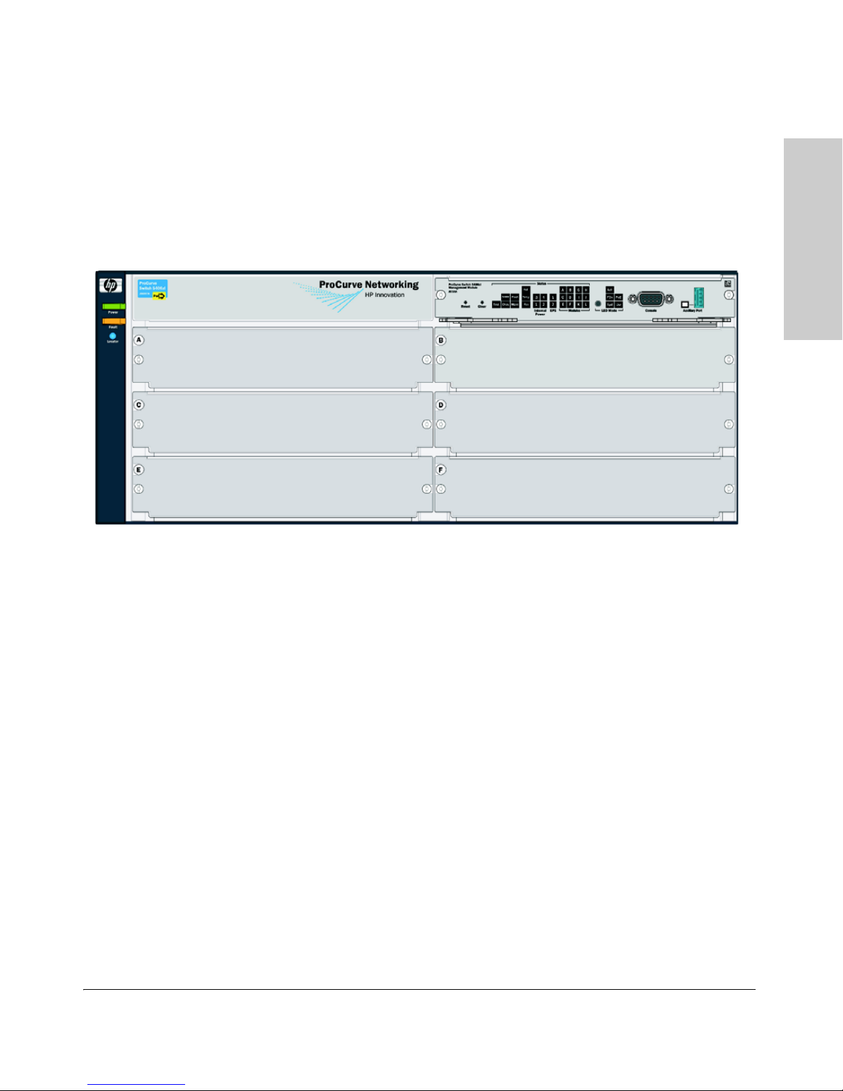
HP ProCurve 5406zl Switch
The HP ProcCurve 5406zl switch ships with the 5400zl Management Module
and open, 6-slot chassis (J8697A). The switch needs at least one power supply
to operate.
Figure 1-1. HP ProCurve 5406zl Switch (J8697A)
1-3

Introducing the HP ProCurve 5400zl Switches
Introducing the HP ProCurve
5400zl Switches
Overview of 5400zl Switches
HP ProCurve 5406zl-48G Switch
The HP ProcCurve 5406zl-48G switch bundle (J8699A) ships with the 5406zl,
6-slot chassis and the following modules and power supply:
• Two 24-port 10/100/1000-T zl Modules (J8702A)
• One 875 W PoE Power Supply (J8712A) pre-installed.
Figure 1-2. HP ProCurve 5406zl-48G Switch bundle (J8699A) with two
10/100/1000-T zl Modules
HP ProCurve 5406zl-48G-PoE+ Switch
The HP ProCurve 5406zl-48G-PoE+ switch bundle (J9447A) ships with the
5406zl, 6-slot chassis and the following modules.
• One 24-port 10/100/1000-T PoE+ zl Modules (J9307A)
• One 20-port 10/100/1000-T PoE+ & 4-port mini-GBIC zl Module
(J9308A)
• One 1500W PoE+ zl Power Supply (J9306A)
1-4
Introducing the HP ProCurve 5400zl Switches
Introducing the HP ProCurve
5400zl Switches
Overview of 5400zl Switches
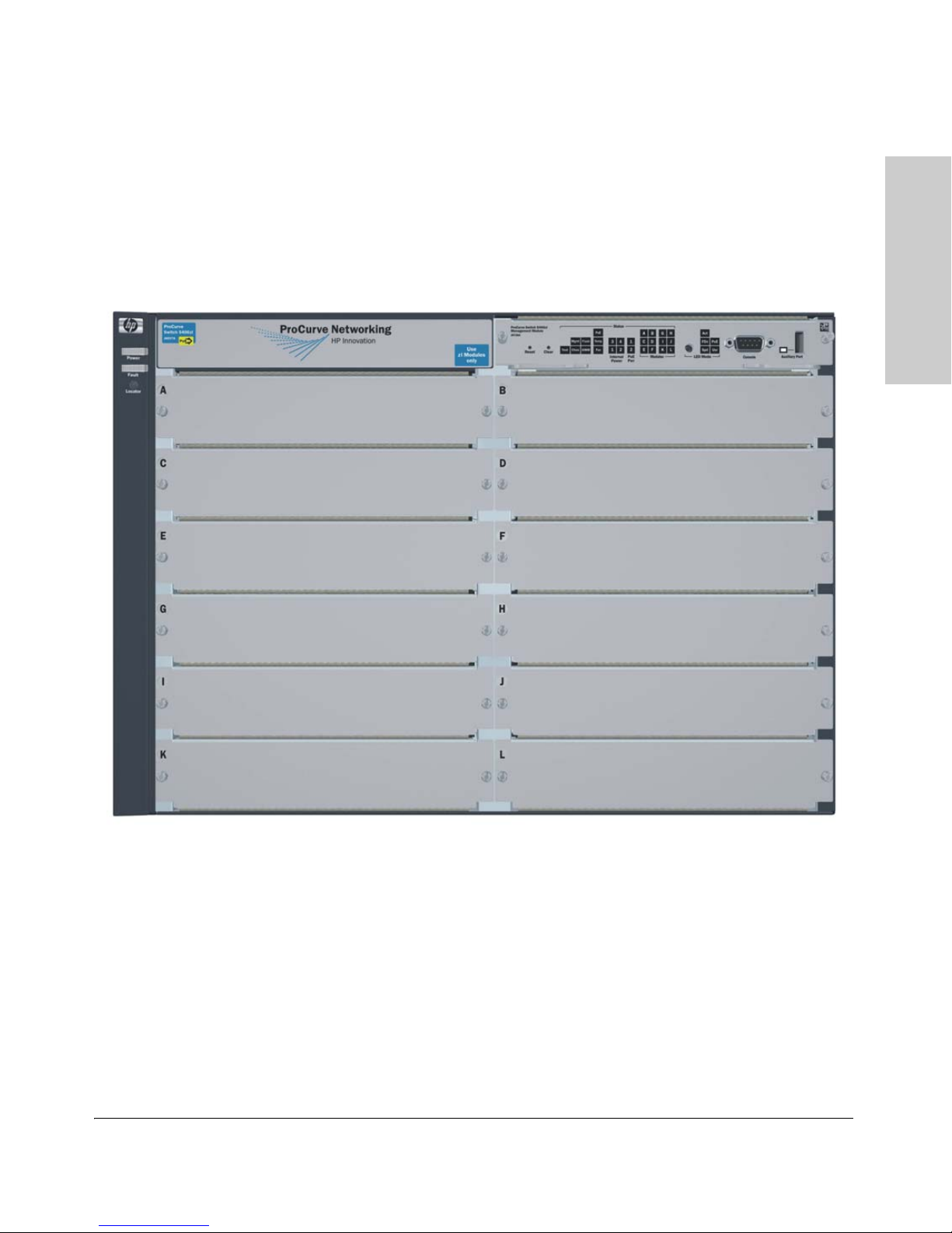
HP ProCurve 5412zl Switch
The HP ProcCurve 5412zl switch ships with the 5400zl Management Module
and open, 12-slot chassis (J8698A). It does not ship with any power supplies.
The switch needs at least one power supply to operate.
Figure 1-3. HP ProCurve 5412zl Switch (J8698A)
1-5
Introducing the HP ProCurve 5400zl Switches
Introducing the HP ProCurve
5400zl Switches
Overview of 5400zl Switches
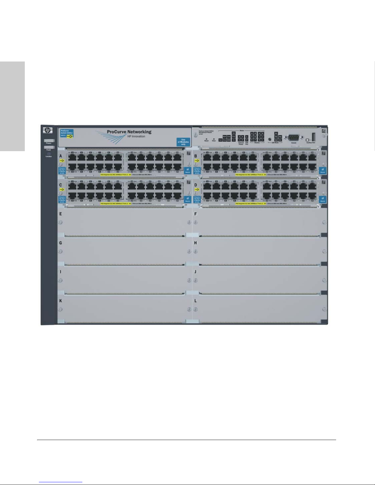
HP ProCurve 5412zl-96G Switch
The HP ProcCurve 5412zl-96G switch bundle (J8700A) ships with the 5412zl,
12 slot chassis and the following modules and power supply:
• Four 24-port 10/100/1000-T zl Modules (J8702A)
• One 875 W PoE Power Supply (J8712A) pre-installed.
Figure 1-4. HP ProCurve 5412zl-96G Switch (J8700A)
HP ProCurve 5412zl-96G-PoE+ Switch
The HP ProcCurve 5412zl-96G-PoE+ switch bundle (J9448A) ships with the
5412zl, 12-slot chassis and the following modules.
• Three 24-port 10/100/1000-T PoE+ zl Modules (J9307A)
• One 20-port 10/100/1000-T PoE+ & 4-port mini-GBIC zl Module
• Two 1500W PoE+ zl Power Supplies (J9306A)
1-6
(J9308A)
Introducing the HP ProCurve 5400zl Switches
Introducing the HP ProCurve
5400zl Switches
Network Connectivity, Speeds and Technologies
Network Connectivity, Speeds and
Technologies
These products support optional network connectivity with the following
speeds and technologies.
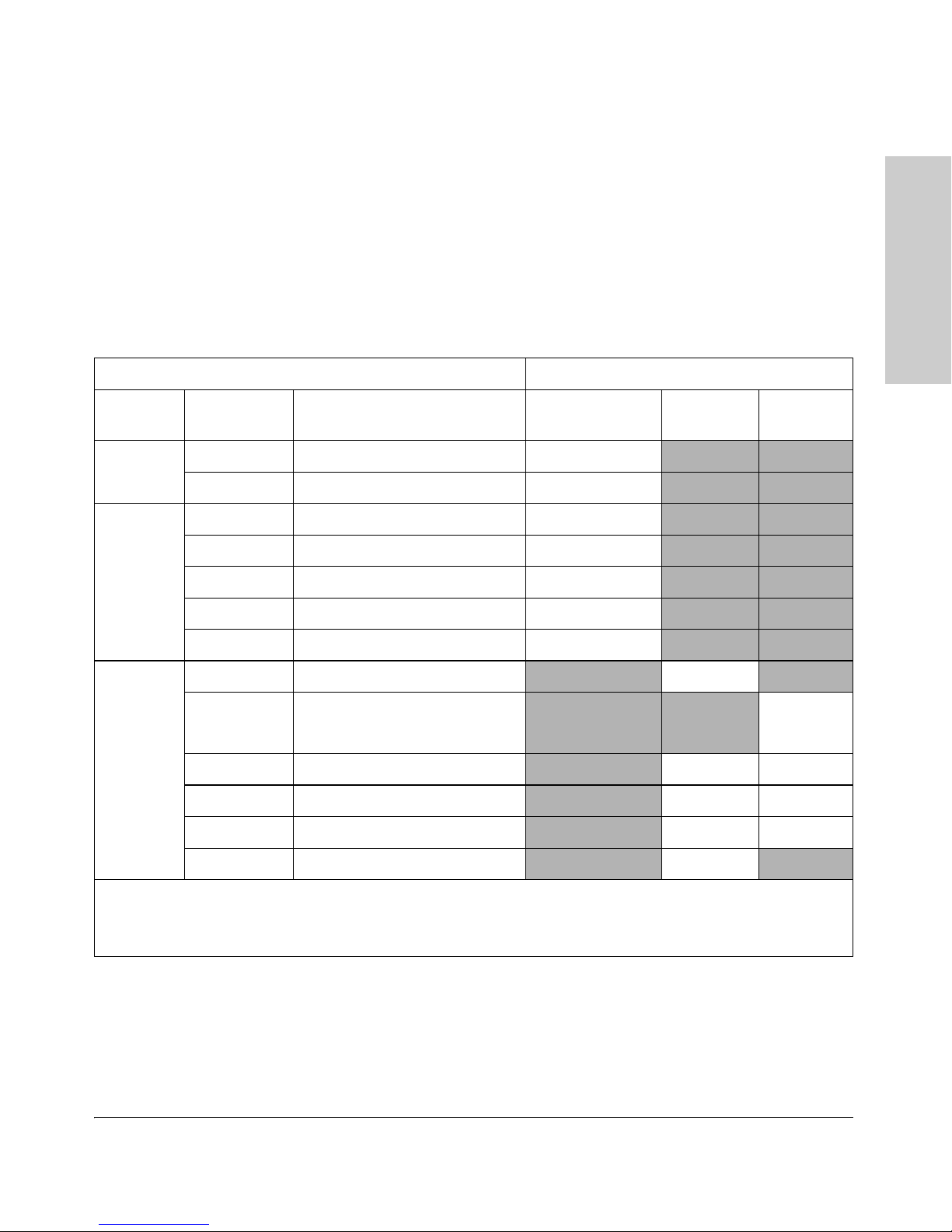
Table 1-1. Optional Network Connectivity, Speeds and Technologies
Transceiver Form-Factor and Connector
Speed Technology Cabling
100-FX Fiber (multimode) LC
100 Mbps
100-BX Fiber (single mode) LC
1000-T Copper (twisted-pair) RJ-45
1
SFP ("mini-GBIC")
Connector
X2
Connector
SFP+
Connector
1000-SX Fiber (multimode) LC
1 Gbps
10 Gbps
1
For supported transceivers, see www.procurve.com/faqs. Both ProCurve 10-GbE Transceivers and ProCurve Mini-
GBICs and SFPs have links to a list of supported products (first question in the "General product information" category).
For technical details of cabling and technologies see "Cabling and Technology Information" in the appendices.
1000-LX Fiber (multimode or single mode) LC
1000-LH Fiber (single mode) LC
1000-BX Fiber (single mode) LC
10-Gig CX4 Copper (twinaxial) CX4
10-Gig
Direct Attach
10-Gig SR Fiber (multimode) SC LC
10-Gig LRM Fiber (multimode) SC LC
10-Gig LR Fiber (single mode) SC LC
10-Gig ER Fiber (single mode) SC
Copper (twinaxial) Not
Applicable
1-7
Introducing the HP ProCurve 5400zl Switches
Introducing the HP ProCurve
5400zl Switches
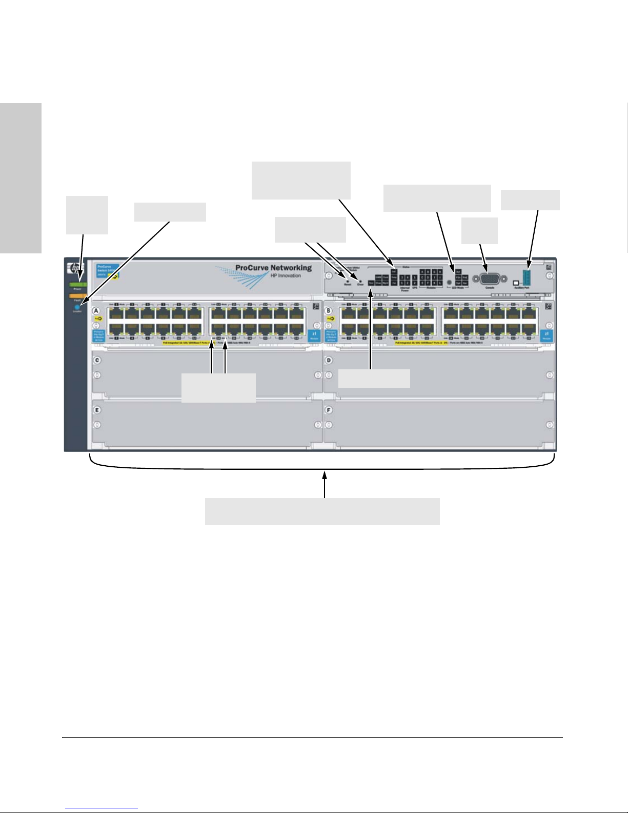
LED Mode Select button
and indicator LEDs
Switch Modules and slots
with Link and Mode LEDs for each port located on each module
Power
and Fault
LEDs
Locator LED
Status LEDs for the
Fans, Power Supplies,
and Switch Modules
Reset and Clear
buttons
Auxiliary Port
Console
Port
Module Link
and Mode LEDs
Self Test LED
Front of the Switch
Front of the Switch
Figure 1-5. Front of 5406zl-48G Switch
This illustration shows the 5406zl-48G (J8699A), but the labeling and descriptions apply to all of the ProCurve Series 5400zl switches.
1-8
Introducing the HP ProCurve
5400zl Switches
LEDs
As described in the next two tables, there are LEDs on the switch chassis and
on the switch modules that keep you informed of the status of the switch and
the network connections.
Table 1-2. Switch Chassis LEDs
LEDs State Meaning
Introducing the HP ProCurve 5400zl Switches
Front of the Switch
Power
(green)
Fault
(orange)
Locator
(blue)
Test
(green/Orange)
DIMM
(green/Orange)
On The switch is receiving power.
Off The switch is NOT receiving power.
Off The normal state; indicates that there are no fault conditions on the switch.
Blinking1A fault has occu rred on the switch, one of the switch modules, an individual port, a power
supply, or a fan. The Status LED for the module or other device with the fault will flash
simultaneously.
On On briefly at the beginning of switch self test after the switch is powered on or reset. If
on for a prolonged time, the switch has encountered a fatal hardware failure, or has
failed its self test. See chapter 4, “Troubleshooting” for more information.
On
Blinking
Off
Off The normal operational state; the switch is not undergoing self test.
On The switch self test and initialization are in progress after you have power cycled or
Blinking1A component of the switch has failed its self test. The Status LED for that component,
On DIMM status is known and fault free.
Off DIMM status is unknown.
The Locator LED is used to locate a specific chassis in a area full of chassis. The LED
can be set to be on solid or blink for a specified number of minutes (1-1440). The default
is 30 minutes. Use the command “chassislocate”.
reset the switch. The switch is not operational until this LED goes off. The Self Test LED
also comes on briefly when you “hot swap” a module into the switch and the module is
automatically self tested.
for example a switch module, and the switch Fault LED will flash simultaneously.
Blinking1If DIMM, Fault, and Self Test LEDs are blinking, DIMM failed self-test.
If DIMM and Fault LEDs are blinking, an operational fault has occurred.
If fast blinking (400ms On and 400ms Off), an operational alert occurred and is
unresolved.
Chas
(green)/Orange
Flash
(green/Orange)
On Flash Card status is known and fault free
Off
Reserved for future releases.
Flash Card status is unknown.
1-9

Introducing the HP ProCurve 5400zl Switches
Introducing the HP ProCurve
5400zl Switches
Front of the Switch
LEDs State Meaning
Blinking1If Flash, Fault, and Self Test LEDs are blinking, Compact Flash failed self-test.
If Flash and Fault LEDs are blinking, an operational fault has occurred.
If fast blinking (400ms On and 400ms Off), an oper ational alert occurred and is unresolved
(for example, the Compact Flash is not present).
Mgmt
(green/Orange)
PoE
(green/Orange)
Temp
(green/Orange)
Fan
(green/Orange)
Internal Power
(green/Orange numbers
corresponding to
the power supply
positions)
On
Off
Blinking
On
Off
Blinking
Blinking
A Management module is present and fault free.
The switch is powered off.
1
There is a fault on the Management module.
If any PoE modules are installed.
If no PoE modules are installed.
1
Internal PoE fault.
2
External load fault or denied PoE power.
Off Switch temperature is normal.
Blinking1An over temperature condition has been detected.
On The cooling fans are operating normally.
Blinking1One or more of the cooling fans have failed. The switch Fault LED will be blinking
simultaneously.
On A power supply is installed in the position in the back of the switch corresponding to the
number, and the supply is plugged in to an active AC power source. As shipped, the
switch has a single power supply in position 1.
Off A power supply is not installed in the position corresponding to the number.
Blinking1The power supply installed in the position corresponding to the number is not plugged
in to an active AC power source, or has experienced a fault. The switch Fault LED will
be blinking simultaneously.
EPS
(green/Orange)
On
Off
An External Power Supply is connected.
No External Power Supply is connected.
Blinking1The External Power Supply has a fault, or is connected but not plugged into AC power.
1-10

Introducing the HP ProCurve
5400zl Switches
LEDs State Meaning
Introducing the HP ProCurve 5400zl Switches
Front of the Switch
Modules (green letters
corresponding to
the switch module
slots)
In PoE Mode:
LED Mode Select
(5 green LEDs)
On A module is installed in the switch module slot corresponding to the letter and the module
is undergoing or has passed self test. This also occurs when you install a module when
the switch is already powered on (“hot swap”).
Off A module is not installed in the switch module slot corresponding to the letter.
Blinking
1
The module status LED flashes very briefly when a module is being hot swapped. If the
LED flashes for a prolonged time, the module in the slot corresponding to the letter has
failed self test or encountered some other fault condition. See chapter 4,
“Troubleshooting” for a more information.
On
Blinking
Blinking2
Off
PoE is ok for this slot.
1
PoE internal fault for this slot.
PoE load fault or insufficient power for this slot.
The module in this slot is not a PoE module.
Act Indicates that the port Mode LEDs are displaying network activity information.
FDx Indicates that the port Mode LEDs are lit for ports that are in Full Duplex Mode.
PoE Indicates which ports are supplying PoE power.
• If the Mode LED is on the port is providing PoE power.
• If the Mode LED is off the port is not providing PoE power.
• If the Link LED is on the port is enabled for PoE.
• If the Link LED is off the port is disabled for PoE.
• If the Link LED is blinking, the port has an error or the port is denied power due to
insufficient power.
Spd Indicates the Port LEDs are displaying the connection speed at which each port is
operating:
• if the Port LED is off, the port is operating at 10 Mbps
• if the Port LED is blinking, the port is operating at 100 Mbps
• if the Port LED is on continuously, the port is operating at 1000 Mbps
Usr Reserved for future development
Auxiliary (green/
orange) For more
Blinking
1
green
Indicates the switch is processing a USB command file.
information see
the Management
and Configuration
Guide for your
switch.
On green The switch has successfully finished processing the USB command file.
Blinking
orange
Indicates an error condition.
2
Off Indicates that no USB device has been inserted, or that the inserted USB device cannot
be recognized, or that no command file can be found on the inserted USB device.
1
The blinking behavior is an on/off cycle once every 1.6 seconds, approximately.
2
The blinking behavior is an on/off cycle once every 0.5 seconds, approximately.
1-11

Introducing the HP ProCurve 5400zl Switches
Introducing the HP ProCurve
5400zl Switches
Front of the Switch
Table 1-3. Switch Module LEDs
These LEDs are located on the modules themselves, one pair for each port.
LED State Meaning
Link On Indicates the port is enabled and receiving a link beat signal (for the twisted-pair
ports), or a strong enough light level (for the fiber-optic ports) from the connected
device.
Off One of these conditions exists:
• no active network cable is connected to the port
• the port is not receiving link beat or sufficient light
• the port has been disabled through the switch console, the web browser
interface, ProCurve Manager, or other network management tool.
Blinking
Mode Depending on the mode selected, displays the following: network activity information, whether
the port is configured for Full Duplex operation, maximum speed operation, or whether PoE
power is being supplied or not. See “LED Mode Select Button and Indicator LEDs” below for
more information.
1
The blinking behavior is an on/off cycle once every 1.6 seconds, approximately.
1
The port has failed self test. The switch Fault, Self Test LEDs, and appropriate
module status LEDs will flash simultaneously.
1-12
Introducing the HP ProCurve 5400zl Switches
Introducing the HP ProCurve
5400zl Switches
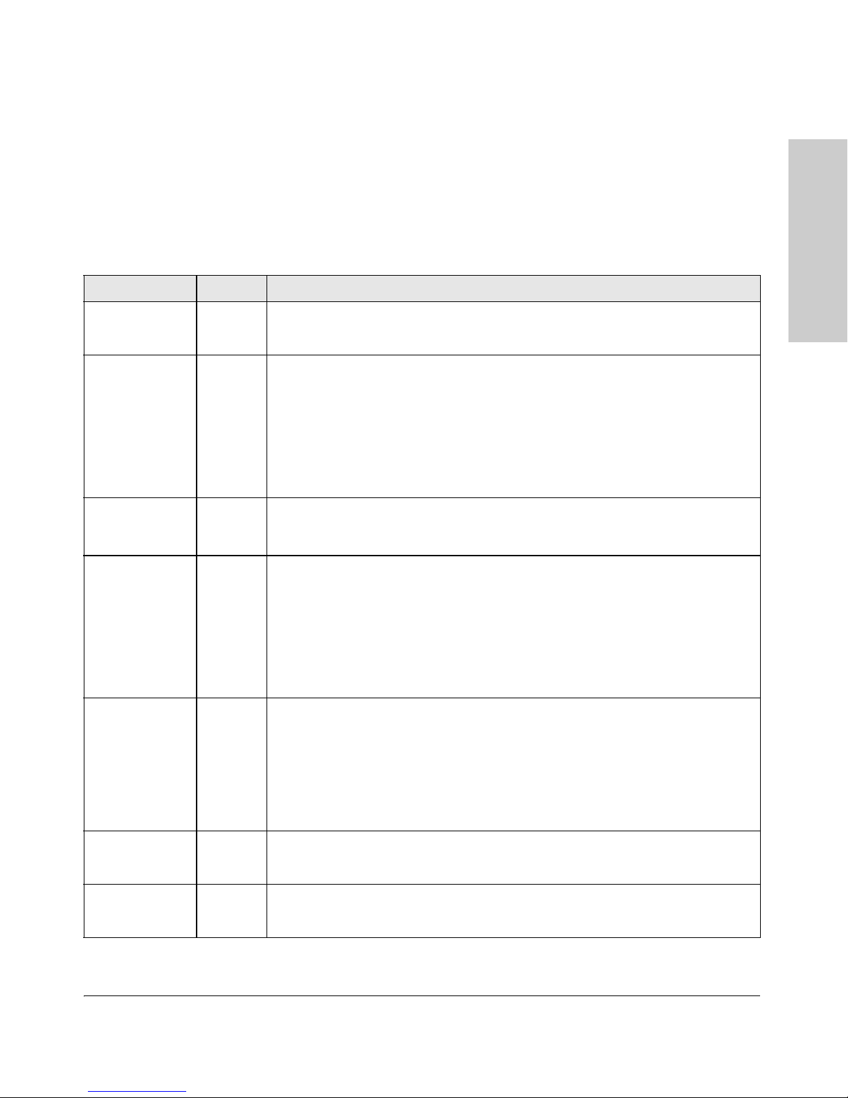
LED Mode Select button
and indicator LEDs
Mode LEDs
(one for each port)
Act
FDx
Spd
PoE
Front of the Switch
LED Mode Select Button and Indicator LEDs
To optimize the amount of information that can be displayed for each of the
switch ports, the 5400zl switches use a Mode LED for each port. The operation
of this LED is controlled by the LED Mode Select button on the switch chassis,
and the current selection is indicated by the mode indicator LEDs near the
button. Press the button to change from one mode to the next.
Figure 1-6. Mode LEDs and LED Mode Select Button
■ If the Activity indicator LED is lit, each port Mode LED displays
activity information for the port—it flickers as network traffic is received
and transmitted through the port.
■ If the Full Duplex indicator LED is lit, the port Mode LEDs light for
those ports that are operating in full duplex.
■ If the speed indicator LED is lit, the port LEDs behave as follows to
indicate the connection speed for the port:
• Off = 10 Mbps
• Blinking = 100 Mbps (the blinking behavior is a repeated on/off cycle
once every 0.5 sec.)
• On = 1000 Mbps
■ If the PoE indicator LED is lit, the Link and Mode LEDs indicate PoE
status:
Link LED:
• On = PoE is enabled on this port
• Off = PoE is disabled on this port.
1-13

Introducing the HP ProCurve 5400zl Switches
Introducing the HP ProCurve
5400zl Switches
Front of the Switch
• Slow Blinking = Internal PoE fault on this port.
• Fast Blinking = This port is denied PoE power or has an external load
fault.
Mode LED:
• On = PoE power is be supplied on this port
• Off = PoE is not being supplied on this port.
Console Port
This port is used to connect a console to the switch by using the serial cable
supplied with the switch. This connection is described under “Connecting a
Console to the Switch” in chapter 2, “Installing the 5400zl Switches”. The
console is a full-featured interface that can be used to configure, monitor, and
troubleshoot the switch. It can be run on a PC, laptop, or handheld device
emulating a VT-100 terminal, or on a standard VT-100 terminal.
Reset Button
This button will reset the switch when powered on. This action clears any
temporary error conditions that may have occurred, executes the switch self
test, and resets all network activity counters to zero. The counters are
displayed in the switch console interface, the switch web browser interface,
and through SNMP network management applications, such as ProCurve
Manager.
Press the Reset button also after changing the module type that is installed in
any of the switch module slots while the switch is powered on. In this case,
the switch must be reset to initialize the new module type. See “Hot Swapping
Switch Modules” on
page 2-26.
Clear Button
This button is used for the following purposes:
■ Deleting Passwords - When pressed by itself for at least one second, the
Clear button deletes any switch console access passwords that you may
have configured. Use this feature if you have misplaced the password and
need console access.
This button is provided for your convenience, but its presence means that
if you are concerned with the security of the switch configuration and
operation, you should make sure the switch is installed in a secure
location, such as a locked wiring closet.
1-14

Introducing the HP ProCurve 5400zl Switches
Introducing the HP ProCurve
5400zl Switches
Front of the Switch
■ Restoring Factory Default Configuration - When pressed with the
Reset button in a specific pattern, the Clear button clears any configura
tion changes you may have made through the switch console, the web
browser interface, or SNMP management, and restores the factory default
configuration to the switch. For the specific method to restore the factory
default configuration, see “Restoring the Factory Default Configuration”
in chapter 4, “Troubleshooting” of this manual.
-
1-15
Introducing the HP ProCurve 5400zl Switches
Introducing the HP ProCurve
5400zl Switches
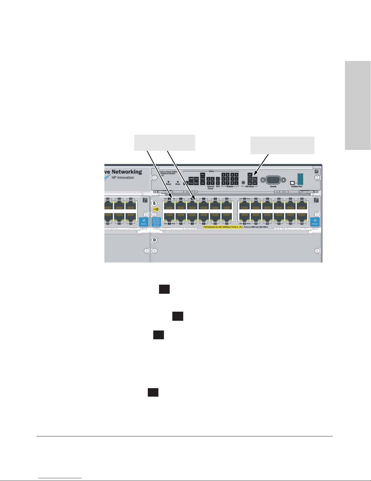
Grounding lug
mounting holes
AC power connector
Power and Fault LEDs
Slot for installing option al
redundant power supply
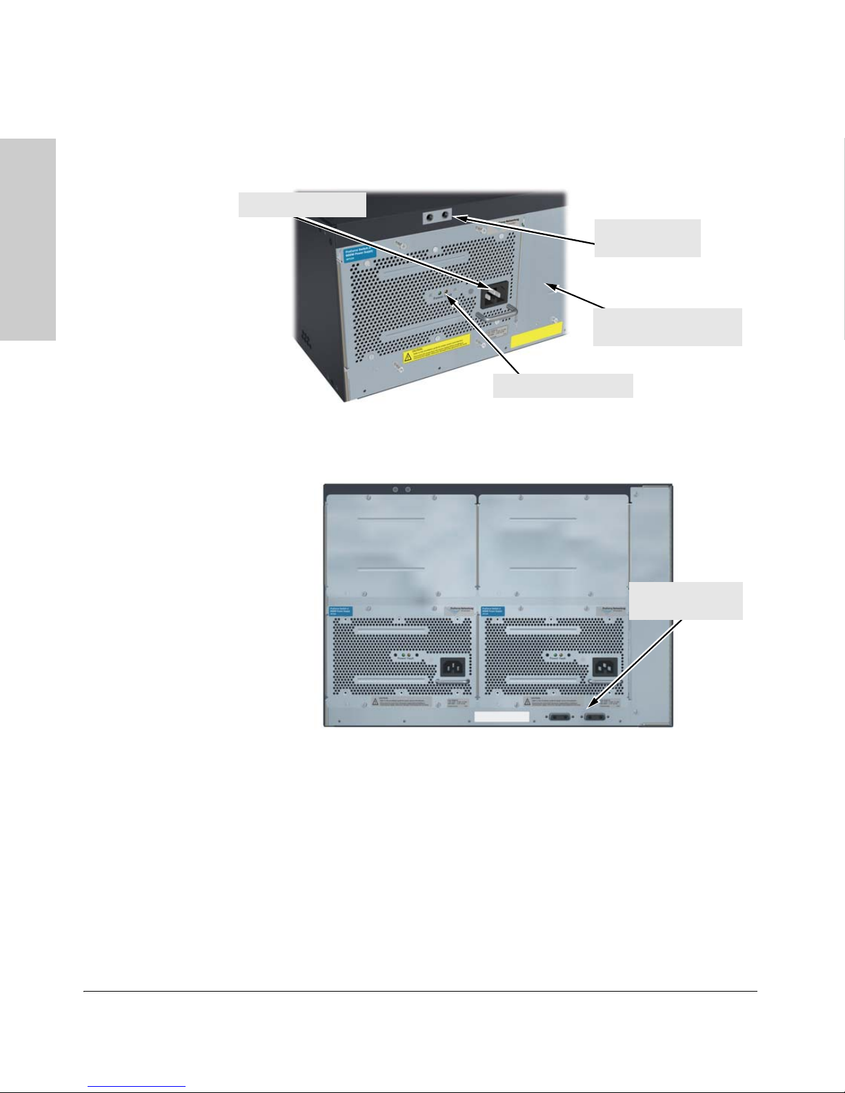
External PoE
power connectors
Back of the Switch
Back of the Switch
.
Figure 1-7. Back of a 5406zl Switch with One Power Supply
Figure 1-8. Back of a 5412zl Switch with two Power Supplies
Power Connector
The Series 5400zl Switches do not have a power switch; they are powered on
when connected to an active AC power source. The 5400zl switches automat
ically adjust to any voltage between 100-127 and 200-240 volts when using the
1-16
J8712A power supply, 200-240 volts when using the J8713A power supply, and
110-127 and 200-240 volts when using the J9306A power supply, and either 50
or 60 Hz. There are no voltage range settings required.
-
Introducing the HP ProCurve 5400zl Switches
Introducing the HP ProCurve
5400zl Switches
CAUTION:
.
.
Disconnect AC power from the power supply BEFORE installing or
removing the supply. Otherwise, damage to the equipment may result.
.
Refer to the installation guide for proper power cord selection
Back of the Switch
Redundant Power Supply
Load-sharing redundant power supplies (HP ProCurve Switch zl 875 W Power
Supply, J8712A, a Switch zl 1500 W Power Supply J8713A, or a Switch zl 1500
W PoE+ Power Supply J9306A) can be installed in the back of the 5400zl
switches. To provide redundancy, each power supply should be connected to
different AC power sources. Then, if one AC power source fails, the switch
will continue to run.
Note The J8712A and J8713A power supplies can be paired within the same switch
or within the Power Supply Shelf. However, the J9306A power supply can only
be paired with another J9306A power supply within the same switch or within
the Power Supply Shelf. The J9306A power supply cannot be used with either
the J8712A or J8713A power supplies.
Caution The switch redundant power supply is hot swappable, but, as indicated by the
caution statement on the power supply, it must be disconnected from AC
power before being installed or removed.
Because the switch can run on a single supply, removing a redundant supply
will not interrupt switch operation. However, on the 5412zl one power supply
will only supply enough power to run the module slots A-F. Slots G-L will not
receive any power unless there are at least two power supplies installed.
When power is restored from a second (or more) power supplies, a system
reload or interface module reset is required to restore operation to slots G-L.
To reset the interface modules, pull each module out about half way and then
reseat them. Do this for each module in slots G-L.
For more information regarding power see the:
■ HP ProCurve Switch zl Internal Power Supply Installation Guide.
■ HP ProCurve PoE (ProCurve Power over Ethernet) Devices Planning
and Implementation Guide.
1-17

Introducing the HP ProCurve 5400zl Switches
Introducing the HP ProCurve
5400zl Switches
Switch Accessories
Switch Accessories
Accessories of the 5400zl switches include a 6 or 12-slot chassis for installing
any of the available zl Modules. The supported zl modules include:
■ 24-Port 10/100/1000 PoE+ zl Module (J9307A)
■ 20-Port 10/100/1000 PoE+/4-Port MiniGBIC zl Module (J9308A)
■ 4-Port 10GbE SFP+ zl Module (J9309A)
■ 24-Port 10/100 PoE+ zl Module (J9478A)
■ 24-port 10/100/1000-T zl PoE Module (J8702A) -- which can provide Power
over Ethernet (PoE) power to 802.3af compliant (and some pre-standard)
devices.
■ 20-port Gig-T and 4-port mini-GBIC/SFP zl PoE Module (J8705A)
■ 24-port mini-GBIC zl Module (J8706A)
■ 4-port 10Gig-X2 zl Module (J8707A)
■ 4-port 10Gig-CX4 zl Module (J8708A)
■ Wireless Edge Services zl Module (J9051A) and Redundant Wireless
Services zl Module (J9052A)
■ ONE Services zl Module (J9289A)
Note For detailed information about the zl modules, refer to the HP ProCurve
Switch zl Modules Installation Guide.
For detailed information about PoE and PoE+ devices, refer to the HP
ProCurve PoE (Power over Ethernet) Devices Planning and Implementation
Guide.
1-18

Introducing the HP ProCurve
5400zl Switches
Introducing the HP ProCurve 5400zl Switches
Switch Features
Switch Features
The features of the 5400zl switches include:*
■ modules can be installed in any order and in any combination and can the
“hot swapped”
■ supported mini-GBICs can be hot swapped into the mini-GBIC zl Module
■ high performance—the 5406 Switch has a routing/switching capacity of
322.8 Gbps, with a switch fabric speed of 345.6 Gbps and a throughput of
249.2 Mpps. The 5412 Switch has a routing/switching capacity of 645.6
Gbps, with a switch fabric speed of 691.2 Gbps and a throughput of 480.3
Mpps
■ plug-and-play networking—all ports are enabled—just connect the
network cables to active network devices and your switched network is
operational
■ automatic learning of the network addresses in the switch’s 16,000-
address forwarding table, with configurable address aging value
■ full-duplex operation available on all ports
■ easy management of the switch through several available interfaces:
• web browser interface—an easy to use built-in graphical interface
that can be accessed from common web browsers
• console interface—a full featured, easy to use, VT-100 terminal interface for out-of-band switch management, or for TELNET access to
the switch. The console includes complete switch management
through a command line interface (CLI) and a slightly reduced feature
set accessible through an intuitive menu interface
• ProCurve Manager—an SNMP-based graphical interface that is used
to manage your entire network, included with your new switch
• supported by ProCurve Network Manager—an HP OpenView application that accurately displays your switch on network maps and
provides a graphical interface for configuring and monitoring your
switch
■ support for the Spanning Tree Protocol to eliminate network loops
■ support for up to 256 IEEE 802.1Q-compliant VLANs so you can divide the
attached end nodes into logical groupings that fit your business needs
■ Layer 3 routing functionality:
•IP static routes
• RIP V1 and V2
1-19

Introducing the HP ProCurve 5400zl Switches
Introducing the HP ProCurve
5400zl Switches
Switch Features
• IRDP - ICMP Router Discovery Protocol
• OSPF- Open Shortest Path First
• DHCP relay
■ support for many other advanced features to enhance network perfor-
mance, security, and control— for a description, see the Management and
Configuration Guide which is on the ProCurve Web site. See
page 5-1 for
details.
■ support for IEEE 802.3af standard, IEEE 802.3 at draft standard, and pre-
standard PoE devices
Note *Some of the listed 5400zl switch features require a Premium License.
1-20
 Loading...