

HP ProCurve 5308XL-48G, ProCurve 5372xl, ProCurve 5348xl, J8166A, J8167A Supplementary Manual
ProCurve Networking by HP
ProCurve Switch 5300xl Series
Reviewers Guide
ProCurve 5300xl Series Switches................................................................................... 4
Background................................................................................................................ 4
ProCurve Networking................................................................................................ 4
Product Overview........................................................................................................ 5
Modules and Power Supplies available for these switches:...........................................5
Product Architecture and Design.................................................................................... 5
Hardware Architecture .............................................................................................. 5
N-Chip................................................................................................................. 6
F-Chip................................................................................................................. 7
The Master CPU .................................................................................................... 7
Packet Buffer Memory Management......................................................................... 7
Performance............................................................................................................ 8
IP Routing (L3) RFC 2285 Fully Meshed Throughput Test ............................................... 8
Copper Gigabit ports..............................................................................................8
100BT Ports ......................................................................................................... 9
Throughput Test Comments.................................................................................... 9
IP Routing (L3) RFC 2245 Latency Test ....................................................................... 9
Copper Gig Ports................................................................................................... 9
100BT Ports ......................................................................................................... 9
Latency Test Comments......................................................................................... 9
Features and Benefits ................................................................................................ 10
Feature Set Summary............................................................................................. 10
High Availability.................................................................................................. 10
Prioritization / QoS.............................................................................................. 10
Security............................................................................................................. 10

Bandwidth Management....................................................................................... 11
Network Management.......................................................................................... 11
Redundancy ....................................................................................................... 11
Service and Support............................................................................................ 12
High Availability..................................................................................................... 12
IP Routing.......................................................................................................... 12
Rapid Spanning Tree Protocol, 802.1w ................................................................... 13
Switch Meshing (LAN Aggregation) ........................................................................ 13
XRRP – Router Redundancy Protocol ...................................................................... 15
Prioritization / QoS................................................................................................. 16
Priority Queues................................................................................................... 16
QoS Classifiers.................................................................................................... 16
IEEE 802.1p Priority Support ................................................................................ 17
Diffserv / TOS Support......................................................................................... 17
End-to-End QoS.................................................................................................. 17
Security................................................................................................................ 17
Virus Throttling................................................................................................... 17
Filtering............................................................................................................. 19
ICMP Rate-Limiting.............................................................................................. 20
802.1X – Port-based access control / RADIUS Authentication..................................... 21
ProCurve Identity Driven Management (IDM).......................................................... 22
TACACS+ Authentication...................................................................................... 22
Port Security - MAC Lockdown............................................................................... 23
Secure Shell – SSH v1 and v2............................................................................... 23
SSL – Secure Sockets Layer ................................................................................. 23
Management VLAN.............................................................................................. 23
SNMPv3 ............................................................................................................. 24
Manager Authorized List....................................................................................... 24
Custom Banner Page ........................................................................................... 24
Intrusion Logs .................................................................................................... 24
Bandwidth Management.......................................................................................... 25
Port Trunking – (Link Aggregation)........................................................................ 25
VLANs ............................................................................................................... 25
IGMP................................................................................................................. 26
Guaranteed Minimum Bandwidth (GMB) ................................................................. 26
Network Management............................................................................................. 28
MIB Support....................................................................................................... 29
RMON Support.................................................................................................... 29
Network Monitoring Port....................................................................................... 29
sFlow Support .................................................................................................... 30
Console Support ................................................................................................. 30
Alert Log............................................................................................................ 30
Redundancy .......................................................................................................... 31
Hot Swap........................................................................................................... 31
Redundant Power Supply...................................................................................... 31
Dual Flash.......................................................................................................... 31
Multiple Configuration Files................................................................................... 31
Service and Support............................................................................................... 31
Lifetime Software Updates (Best in the Industry)..................................................... 31
Lifetime Warranty (Best in the Industry)................................................................. 31

Telephone Support.............................................................................................. 32
Optional Support Services .................................................................................... 32
Appendix ................................................................................................................. 33
ProCurve Networking Adaptive EDGE Architecture™.................................................... 33
ProCurve Switch Positioning..................................................................................... 34
Positioning for the ProCurve 5308xl Switch............................................................. 35
Positioning for the ProCurve 5304xl Switch............................................................. 35
ProCurve Networking Web Site................................................................................. 35
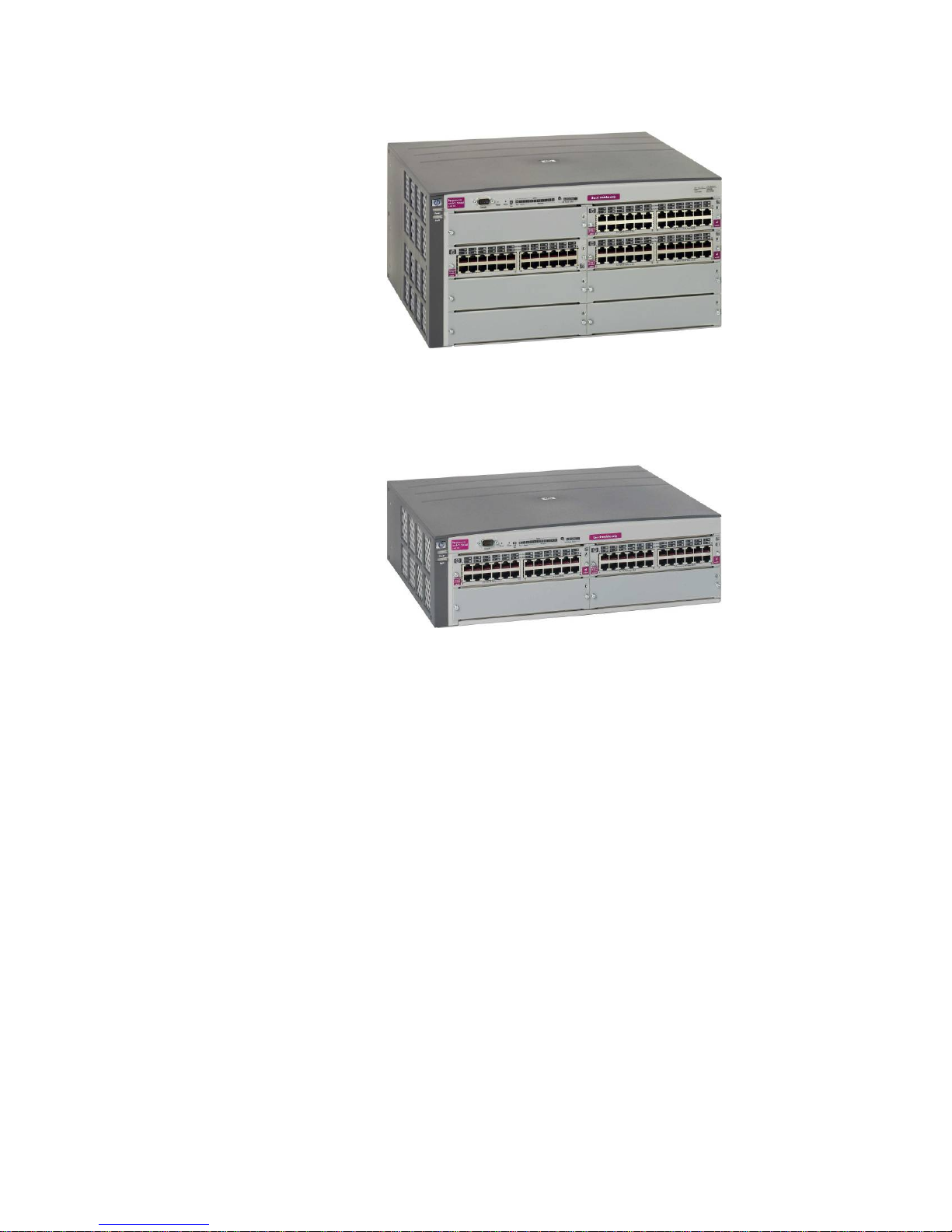
ProCurve 5300xl Series Switches
ProCurve 5372xl Switch
ProCurve 5348xl Switch
Background
This ProCurve 5300xl Switch Series Reviewer’s Guide will help network engineers at computer
trade publications, resellers and end-user sites evaluate the merits of the ProCurve 5300
switches.
ProCurve Networking
ProCurve Networking has an extensible line of products working together to provide the control
network administrators need to deliver the network uptime and performance that their
organizations require. This guide describes one part of ProCurve Networking: the ProCurve
5300xl Switch Series products.
4

Product Overview
The ProCurve 5300xl Series Switches offers scalable layer 2, 3 and 4 switching in compact 4 or
8 slot modular form factors. The 5300xl Series Switches include the 4-slot Switch 5304xl and its
bundles, the Switch 5348xl and the Switch 5304xl-32G, and the 8-slot Switch 5308xl and its
bundles, the Switch 5372xl and the Switch 5308xl-48G. Any of the Switch 5300xl modules can
be put in any of the 5300xl Series slots.
ProCurve 5304xl -32G Switch (J8166A)
The ProCurve 5304xl -32G Switch bundles 32 10/100/1000 ports in a 5304XL chassi s, leaving 2
open slots.
ProCurve 5308xl -48G Switch (J8167A)
The ProCurve 5308xl -48G Switch bundles 48 10/100/1000 ports in a 5308XL chassi s, leaving 5
open slots.
Modules and Power Supplies available for these switches:
ProCurve Switch xl 10/100Base-TX module (J4820B) 24 ports of 10/100Base-T
•
• ProCurve Switch xl 100/1000-T module (J4821B) 4 ports of 100/1000Base-T (no 10Mb
support)
• ProCurve Switch xl 100FX MTRJ module (J4852A) 12 ports of 100FX MTRJ connectors
• ProCurve Switch xl Access Controller Module (J8162A)
• ProCurve Wireless Edge Services xl Module (J9001A)
• ProCurve Redundant Wireless Edge Services xl Module (J9003A)
• ProCurve Switch xl 10/100-TX PoE (Power over Ethernet) module (J8161A) 24 auto-sensing
10/100 IEEE 802.3af PoE (Power over Ethernet)-ready ports.
• ProCurve Switch xl 16-Port 10/100/1000 module (J4907A) 14 ports of auto-sensing
10/100/1000 ports and 2 dual personality ports (10/100/1000 or mini-GBIC)
• ProCurve Switch xl mini-GBIC module (J4878B) 4 ports of mini-GBIC connectivity
• ProCurve Gigabit-SX-LC Mini-GBIC (J4858A)
• ProCurve Gigabit-LX-LC Mini-GBIC (J4859A)
• ProCurve Gigabit-LH-LC Mini-GBIC (J4860A)
• ProCurve 600 Redundant and External Power Supply (J8168A)
• ProCurve Switch gl/xl Redundant Power Supply (J4839A)
• ProCurve 610 External Power Supply (J8169A)
Product Architecture and Design
Hardware Architecture
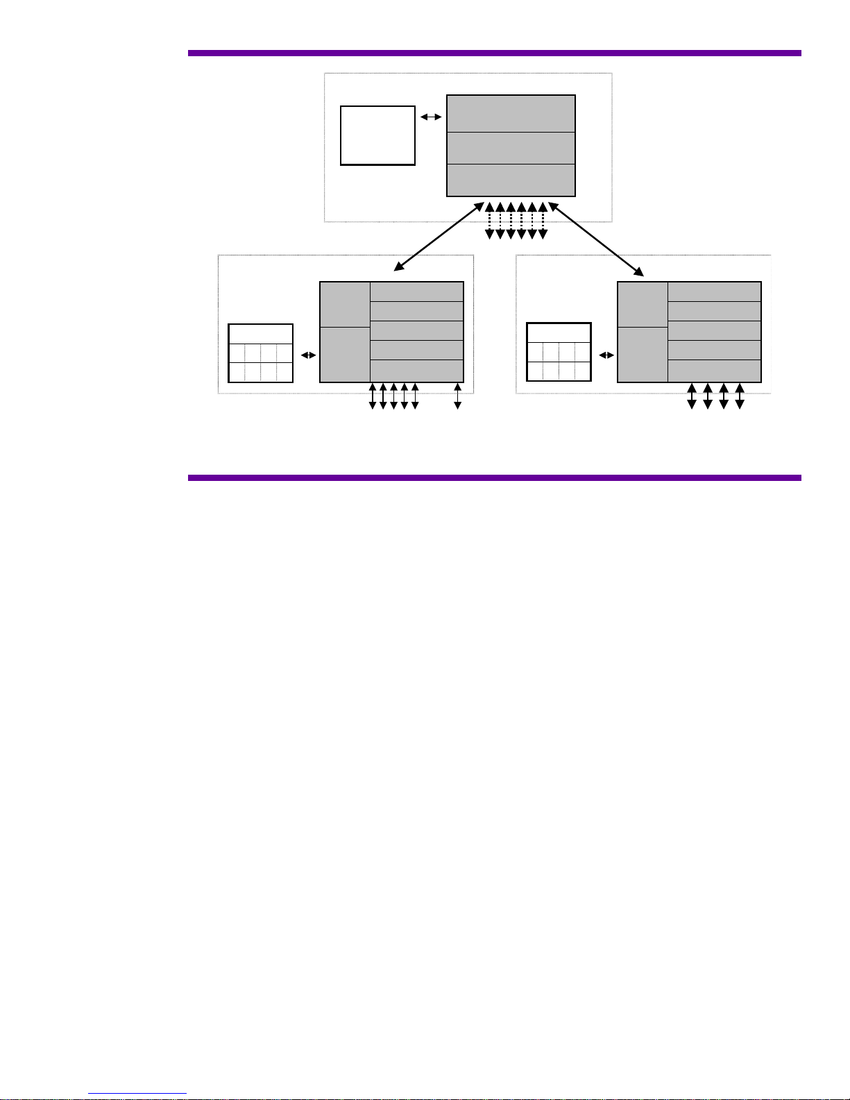
The 5300xl Series Switch architecture is based on 2 different PROCURVE designed ASIC
(Application Specific Integrated Circuits): the Network or N-Chip, and the Fabric or F-Chip.
Each 5300xl switch module has an N-Chip that provides on-module routing and switching
functions. It also provides the high speed connection to the backplane. The F-Chip, located on
the backplane, provides the wire speed crossbar fabric interconnecting all the ports. This
combination of highly integrated N-Chips connected through the F-Chip gives the ProCurve
5300xl Switch Series the ability to deliver wire-speed Layer 3 for the price of Layer 2 switching,
and in a chassis form factor.
5
F-Chip
Management
CPU
Subsystem
CPU Interface
Cross Bar Fabric
Fabric Buffer
9.6 Gbps
Table Memory
Table Memory
Input Memory
Input Memory
Output Memory
Output Memory
N-Chip
CPU
Memory
Subsystem
backplane link
Fabric Interface
Programmable
Look-up
Classifier
24 10/100 MACs
4 GbE MACs
8 Fabric Ports
Output Memory
Output Memory
Table Memory
Table Memory
Input Memory
Input Memory
CPU
Memory
Subsystem
N-Chip
Fabric Interface
Programmable
Look-up
Classifier
24 10/100 MACs
4 GbE MACs
...
Figure 1. Detailed Architecture
The ProCurve 5300xl Switch Series have two slots in the back for the load-sharing power
supplies. One power supply ships standard with each switch and can power a fully loaded
chassis. A second power supply can be installed for redundancy and longer overall expected
power supply life.
The ProCurve 5300xl Switch Series can hold up to 16,536 (16K) MAC addresses in the switch
address table.
N-Chip
Each module contains a full ASIC-based Layer 3 routing switch engine. This switch engine,
called the network or N-Chip, provides all the packet processing: Layer 2 and Layer 3 lookups,
filtering and forwarding decisions, VLAN, trunking and priority queuing determi n ations. The
N-Chip also contains its own CPU.
Classification and Lookup
When a packet first comes in, the classifier section determines the packet characteristics, its
addresses, VLAN affiliation, any priority specification, etc. The packet is stored in input memory,
lookups into the table memory are done to determine routing information and a N-Chip specific
packet header is created for this packet with this information. This header is then forwarded to
the programmable section of the N-Chip.
N-Chip Programmability
As mentioned in the previous section, one of the functions of the N-Chip is to analyze each
packet’s header as it comes into the switch. The packet’s addresses can be read, with the switch
making forwarding decisions based on this analysis. For example, if a packet’s 802.1Q tag
needs to be changed to re-map the packet priority, the N-Chip needs to look at each packet to
see if any particular one needs to be changed. This packet-by-packet processing has to occur
very quickly to maintain overall wire-speed performance. ASICs provide this high performance,
but typically cannot be changed in their functionality once the ASIC design is frozen.
To broaden the flexibility of the N-Chip, a programmable function is included in some areas of
its packet processing. This programmability provides network processor-like capability, giving
the PROCURVE designers the opportunity to make some future changes or additions in the
packet processing features of the ASIC by downloading new software into it. Thus new features
needing high performance ASIC processing can be accommodated, extending the useful life of
the switch without the need to upgrade or replace the hardware.
6

This programmable functionality was originally designed and implemented in the popular
ProCurve Switch 4000M switch family and was used to give the ProCurve Switch 4000M new
ASIC-related features well after initial release of the product. Customers with existing units
could benefit from the new features via a free software download. The customer’s investment in
the Switch 4000M was preserved by providing new functionality not otherwise possible without
the ASIC programmability.
Being based on the Switch 4000M’s implementation, the ProCurve 5300xl programmable
capability is a second generation design.
Fabric Interface
After the packet header leaves the programmable section, the header is forwarded to the Fabric
Interface. The Fabric Interface makes final adjustments to the header based on priority
information, multicast grouping, etc. and then uses this header to modify the actual packet
header as necessary.
The Fabric Interface then negotiates with the destination N-Chip for outbound packet buffer
space. If congestion on the outbound port is present, WRED (weighted random early detection)
can also be applied at this point as a congestion avoidance mechanism.
Finally the N-Chip Fabric Interface forwards the entire packet through the F-Chip to an awaiting
output buffer on the N-Chip that controls the outbound port for the packet. Packet transfer from
the N-Chip to the F-Chip is provided via the 9.6Gbps full duplex backplane connection, also
managed by the Fabric Interface.
The N-Chip CPU
The N-Chip contains its own CPU, a 66 MHz ARM-7, for Layer 2 learns, packet sampling for the
XRMON function, handling local MIB counters and running other module related operations.
Overall, the local CPU offloads the master CPU by providing a distributed approach to general
housekeeping tasks associated with every packet. MIB variables, which need to be updated with
each packet, can be done locally. The Layer 2 forwarding table is kept fresh via this CPU. Other
per-port protocols, such as Spanning Tree and LACP, are also run on this CPU.
The local CPU, being a full-function microprocessor, allows functionality updates through future
software releases.
F-Chip
The fabric, or F-Chip, which is located on the backplane of the switch, provides the crossbar
fabric for interconnecting the modules together. The use of a crossbar allows wire speed
connections simultaneously from any module to any other module. As mentioned in the N-Chip
section, the connection between the F-Chip and each N-Chip (module) in the chassis is through
a 9.6Gbps full duplex link.
One unique function of the F-Chip is to automatically replicate multicast packets and send them
to the destination modules. This method is more efficient than having the source N-Chip do the
replication. Since only a single copy of the multicast packet needs to be sent to the F-Chip, this
method saves bandwidth on the high speed connection between the source N-Chip and the FChip.
The Master CPU
Along with the F-Chip, the backplane of the switch also contains the master CPU, 32MB RAM
and 12MB of flash ROM memory. The master CPU, a 200 MHz Power PC 8240, runs the routing
protocols and maintains the master routing tables, maintains the master MIBs, responds to
SNMP requests, and manages the user interfaces. The Master CPU is also responsible for switch
bootup coordination. Two copies of the switch operating system can be stored in the flash ROM.
This allows the user to recover quickly if the main code copy is corrupted or a code update
produces results other than what is desired.
Input to the CPU is prioritized into 4 queues. Queuing this way prevents the user from being
locked out of the switch user interface due to unintentional high levels of traffic, such as
broadcast storms. More significantly, this also prevents a user lockout due to intentionally high
levels of traffic, such as denial of service attacks.
Packet Buffer Memory Management
Each 5300xl module uses 6.2MB for the outbound packet buffer memory, arranged as 4096
buffers of 1518 bytes in length (the maximum Ethernet packet size). This memory is divided
7
evenly across the number of ports on the module. For example, the Switch xl 100/1000-T
÷
module, which has 4 100/1000 ports, has
44096
= 1024 outbound packet buffers per port,
whereas the Switch xl 10/100Base-TX module, which has 24 10/100 ports has 4096÷24 = 170
outbound packet buffers per port.
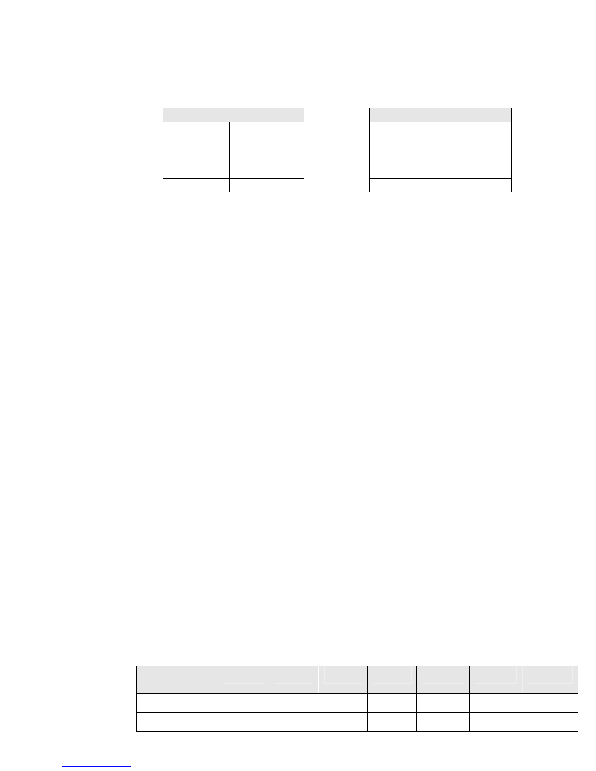
The QoS queues for each port are then represented by their weighted percentage.
10/100 Modules
Queue Weight Queue Weight
1 10% 1 25%
2 60% 2 25%
3 10% 3 25%
4 20% 4 25%
Gigabit Modules
Queue 2 for a Gigabit module has 1024 x 25% = 256 packet buffers. Queue 2 for a 10/100
module would have 170 x 60% = 102 packet buffers.
Inbound buffer memory is normally run to be just a few packets deep to avoid head of line
blocking issues. If flow control is turned on for a port the amount of inbound packet memory
available to that port is quite deep – 1 MB or more.
Packet Buffer Memory Design Tradeoffs
In general, buffer memory is a difficult topic as the common assumption is that more is better.
That is not the case, particularly for inbound memory. Head of line blocking is a big issue with
inbound memory that has any depth, so in many cases the effective depth is usually set to be
quite small - several packets deep to account for processing 'jitter' of the ASIC as it handles
packets of differing types. Since the packet processor in the 5300 N-chip runs at wire-speed for
our current modules we shouldn't be dropping any packets on the inbound side due to packet
processing delays - packets would only get dropped if there is outbound congestion.
Outbound memory size does better with larger queue depths, but even here there is a concern
with queues that are too deep. You don't want to hang on to a packet too long as the latency
the packet accumulates in the switch has potential network effects, such as retransmission
requests or session timeouts. In the case of VoIP packets and streaming video packets this
latency can cause stream dropouts at the destination.
The 5300 buffer design tries to strike a balance on what is needed for packet buffering to deal
with network congestion versus the ability of holding on to packets too long and actually
exacerbating poor network performance. You don't want to compensate for oversubscribed
networks (looking on a QoS queue-by-queue basis) by trying to over buffer in the switch.
Performance
These numbers have been generated by Hewlett-Packard, using testers from Ixia
Communications. Ixia testers are used by a number of network testing houses and the press to
determine performance numbers for networking equipment. In these tests, 32 ports were used
for Gigabit testing, 192 ports for 100 Mb testing. All ports were full duplex. Numbers presented
here are condensed from Ixia reports in order to save space.
Testing done on the ProCurve 5308xl Switch . Maximum rate of throughput (100%) would be
the same for the 5304xl but at one-half the number of packets since the 5304xl has one-half
the possible number of ports of the 5308xl.
IP Routing (L3) RFC 2285 Fully Meshed Throughput Test
Copper Gigabit ports
Port pairs active, full duplex: 32 = 32 Gbps data out of the tester
Test length: 5 minutes
Packet size
(bytes)
%MaxRate
TotalTxFrames
64 128 256 512 1024 1280 1518
100 100 100 100 100 100 100
14285711648 8108112000 4347829856 2255634400 1149426432 923077824 780229824
8
TotalRxFrames
2
14285711648 8108112000 4347829856 2255634400 1149426432 923077824 780229824
TotalLoss(%)
0.000 0.000 0.000 0.000 0.000 0.000 0.000
100BT Ports
Port pairs active, full duplex: 192 = 19.2 Gbps data out of the tester
Test length: 3 hours
Packet size
(bytes)
%MaxRate
TotalTxFrames
TotalRxFrames
TotalLoss(%)
64 128 256 512 1024 1280 1518
100 100 100 100 100 100 100
308572144115 175134177024 93913320982 48721238434 24827090688 19937539584 16852104
308572144115 175134177024 93913320982 48721238434 24827090688 19937539584 16852104
0.000 0.000 0.000 0.000 0.000 0.000 0.000
Throughput Test Comments
A fully meshed performance test sends packets from each port to every other port during the
test. This test exercises both the modules and the backplane. These tests show the ProCurve
5300xl Switch Series to be wire-speed on all ports simultaneously. The 5300 is the only chassi s
in its price range that is wire-speed on all ports simultaneously at Layer 2 or Layer 3.
IP Routing (L3) RFC 2245 Latency Test
Copper Gig Ports
Port pairs active, full duplex: 32
All latencies in microseconds
Frame Size 64 128 256 512 1024 1280 1518
AvgLatency(μs) 5.802 6.746 8.085 11.731 18.067 21.104 23.940
100BT Ports
Port pairs active, full duplex: 192
All latencies in microseconds
Frame Size 64 128 256 512 1024 1280 1518
AvgLatency(μs) 24.36 36.26 42.38 81.44 136.46 166.42 200.8
Latency Test Comments
Latency is measured as the time it takes for a byte inside a packet to enter and then leave the
switch. This measurement includes both the processing time of the switch as it makes its
forwarding decision and the time for the packet itself to enter and leave the switch.
The latency figures for the ProCurve 5300xl Switch Series are low. Latencies this low will not be
a factor in general network operation, even with streaming video or VoIP applications.
Almost all switches currently on the market, the 5300 included, are store and forward, so the
entire packet is received into the switch before the switch starts to transmit it out the outgoing
port. The above latency figures include this packet receive time. For example, at 100Mbps it
takes 5.76 μsec for a 64 byte packet, and 122.08 μsec for a 1518 byte packet itself to move into
and out of the switch. At 1Gbps a 64 byte packet takes 576 ηseconds, while a 1518 byte packet
takes 12.208 μsec. Adding the packet receive time to the latency is proper because this extra
time is seen externally to the switch by the network and figures in to the transit time of the
packet as it moves through the network.
9

Features and Benefits
Feature Set Summary
High Availability
IP Routing Features:
•
RIP (v1, v2, and v1 compatible v2) support.
OSPF v2 and OSPF ECMP (Equal Cost Multi-Path) support.
Static IP routes – To manually add routes directly to the routing table.
10,000 network address routes, 65,536 (64K) L3 host address routes
IPv4 routing, IPv6 switching
16 multi-netted interfaces per VLAN
• IRDP (ICMP Router Discovery Protocol) – To advertise the IP addresses of the switch router
interfaces to the directly attached hosts.
• DHCP relay – Allows DHCP requests to be forwarded to links associated with the DHCP server
• UDP broadcast forwarding for applications that require clients to send limited UDP broadcast
to a specific UDP port.
• IEEE 802.1w Rapid Spanning Tree Protocol support – provides very fast Spanning Tree
convergence (approaching 1 second under optimal conditions) on lost links or when the root
switch is unreachable. Compatible with switches running 802.1D Spanning Tree.
• XRRP Router Redundancy Protocol: Two 5300s can back each other up for Layer 3 interfaces.
Failure detection and switch-over can be as fast as 3 seconds.
• ProCurve Layer 2 Switch Meshing: Allows fully meshed connections between switches at layer
2 with all links being used to send traffic.
• LLDP (Link Layer Discovery Protocol) support to discover neighboring devices.
• IGMP (Internet Group Management Protocol) – controls IP multicast and reduce unnecessary
bandwidth usage on a per-port basis.
Prioritization / QoS
Four priority queues
•
• Traffic prioritization based on:
UDP/TCP Application Type (port number)
Device Priority (destination or source IP address)
IP Type of Service (ToS/Diffserv) field (IP packets only)
Protocol Priority (IP, IPX, ARP, DEC LAT, AppleTalk, SNA, and NetBEUI)
VLAN Priority
Incoming source-port on the switch
Incoming 802.1p Priority (present in tagged VLAN environments)
Security
Virus Throttling (Connection Rate Filtering)– Thwarts virus spreading by blocking routing from
•
certain host exhibiting abnormal traffic behavior.
• ICMP rate-limiting – Throttles denial-of-service (DoS) attacks or other malicious behaviors
that uses high volume ICMP traffic.
• Filtering capabilities include Access Control Lists (ACLs), source port, multicast MAC address
and protocol filtering capabilities.
• 802.1X – client based access control
• RADIUS / TACACS+ authentication
• ProCurve Identity Driven Manager (IDM) to dynamically apply security, access and
performance settings to infrastructure devices based on approved user, location and time.
• Port security, MAC lockdown and MAC lockout protection – Restrict access to the network
through the switch port based on the connected host MAC address.
• Static NAT – hide up to 32 nodes per switch from the rest of the network through static IP
address translation.
10

• Retrict switch console access with local username and password security for manager and
operator level access.
• Web-based and MAC-based authentication – Protects the network from unauthrorized users or
devices.
• SSH v1 and v2 – secure remote access to the management functions of the switch via
encrypted.
• SSLv3 and TLSv1 – secure interaction between a browser and the 5300’s management GU I
interface
• Secure FTP (sftp)– Protects against unwanted file downloads or unauthorized copying of
switch configuration file (tftp must be disabled to enable Secure FTP).
• Management VLAN – Limit CLI/GUI/telnet/SNMP access to the switch to a particular VLAN
• Manager authorized list – Limit CLI/GUI/telnet/SNMP access to the switch to the authorized
hosts.
• Custom banner page - Display access policies or login banners when a user connects to the
switch management interface.
• Intrusion logs – Provides a history of security violation attempts on the switch.
Bandwidth Management
802.3ad LACP (Port Trunks) – (Link Aggregation Control Protocol) Switch-to-switch and
•
switch-to-server aggregated links allow scalable bandwidth communication. Can be used in
many cases to trunk to non-ProCurve devices.
• 256 VLANs, 802.1Q compliant, Layer 2 port-based, for segmentation of LANs
• Support of GVRP (part of 802.1Q) for automatic configuration of VLANs throughout a layer 2
environment
• IGMPv3, IGMP snooping, data-driven IGMP
• Guaranteed Minimum Bandwidth (GMB) – Ensures a minimum bandwidth for the outbound
traffic on a given switch port to prevent from been starved by high volumes of higher-priority
traffic.
Network Management
Web-based management for anytime, anywhere configuration access
•
• ProCurve Manager and ProCurve Manager Plus for centralized device management,
accountability, traffic analysis and others.
• ProCurve Manager For Hubs & Switches integration into HP OpenView-NT
• HP OpenView/NT native application via the ProCurve network management for OV-NT product
• HP OpenView/UX native application via the ProCurve network management f or OV-UX product
• Alert Log capability which finds common network problems and informs the net manager of
the situation
• SNMP v1, v2 and v3, SNMP Traps and MIB II support to manage the switch from a network
management station.
• Ability to configure a network monitoring port (mirror port) for use with external probes or
analyzers
• ProCurve’s Extended RMON and sFlow support allows monitoring of overall traffic levels,
segments with the highest traffic, or even the top users within a network segment
• RADIUS Authorized Manager-Level Login
• RADIUS Authentication for 5300xl Web Browser Access
• 802.1X Open VLAN Browser Access
• 802.1X Open VLAN Delay Option
• HTTP Support for PoE
Redundancy
Hot swap capability, load-sharing power supplies, dual flash memory
•
• Multiple Configuration Files
11
 Loading...