

Page 1

HP ProCurve Wireless
Access Point 520wl
User Guide -
For Software Version 2.4.5
Page 2

©
Copyright 2004, Hewlett-Packard Development
Company, L.P. The information contained herein is
subject to change without notice.
This document contains proprietary information, which is
protected by copyright. No part of this document may be
photocopied, reproduced, or translated into another
language without the prior written consent of HewlettPackard.
Warranty
See the Customer Support/Warranty booklet included
with the product.
A copy of the specific warranty terms applicable to you
Hewlett-Packard products and replacement parts can b
obtained from your HP Sales and Service Office or
authorized dealer.
r
Publication Number
5990-6056
March 2004
Applicable Products
HP ProCurve Wireless AP 520wl (HP J8133A)
Trademark Credits
Microsoft
are US registered trademarks of Microsoft Corporation.
Disclaimer
HEWLETT-PACKARD COMPANY MAKES NO
WARRANTY OF ANY KIND WITH REGARD TO THIS
MATERIAL, INCLUDING BUT NOT LIMITED TO, THE
IMPLIED WARRANTIES OF MERCHANTABILITY AND
FITNESS FOR A PARTICULAR PURPOSE. HewlettPackard shall not be liable for errors contained herein or
for incidental or consequential damages in connection
with the furnishing, performance or use of this material.
The only warranties for HP products and services are set
forth in the express warranty statements accompanying
such products and services. Nothing herein should be
construed as constituting an additional warranty. HP shall
not be liable for technical or editorial errors or omissions
contained herein.
Hewlett-Packard assumes no responsibility for the use or
reliability of its software on equipment that is not
furnished by Hewlett-Packard.
®
, Word®, WordPad®, and Internet Explorer
®
Safety Considerations
Prior to the installation and use of this product, review
safety markings and instructions.
Notes and Cautions
NOTE:
A Note indicates important information that help
you make better use of your computer.
CAUTION:
!
A Caution indicates either potential damage to
hardware or loss of data and tells you how to
avoid the problem.
a
ii
Page 3

Contents
Regulatory Information
Safety Information . . . . . . . . . . . . . . . . . . . . . . . . . . . . . . . . . . . . . . . . . . . . . . . . . . . . . viii
Grounding . . . . . . . . . . . . . . . . . . . . . . . . . . . . . . . . . . . . . . . . . . . . . . . . . . . . . . . . . . . . . . . . viii
Servicing . . . . . . . . . . . . . . . . . . . . . . . . . . . . . . . . . . . . . . . . . . . . . . . . . . . . . . . . . . . . . . . . . viii
Accessories . . . . . . . . . . . . . . . . . . . . . . . . . . . . . . . . . . . . . . . . . . . . . . . . . . . . . . . . . . . . . . . viii
Informations concernant la sécurité. . . . . . . . . . . . . . . . . . . . . . . . . . . . . . . . . . . . . . . . . . . . . . ix
Hinweise zur Sicherheit . . . . . . . . . . . . . . . . . . . . . . . . . . . . . . . . . . . . . . . . . . . . . . . . . . . . . . . x
Considerazioni sulla sicurezza . . . . . . . . . . . . . . . . . . . . . . . . . . . . . . . . . . . . . . . . . . . . . . . . . xi
Consideraciones sobre seguridad . . . . . . . . . . . . . . . . . . . . . . . . . . . . . . . . . . . . . . . . . . . . . . xii
Safety Information (Japan) . . . . . . . . . . . . . . . . . . . . . . . . . . . . . . . . . . . . . . . . . . . . . . . . . . . xiii
Safety Information (China). . . . . . . . . . . . . . . . . . . . . . . . . . . . . . . . . . . . . . . . . . . . . . . . . . . . xiv
EMC Regulatory Statements . . . . . . . . . . . . . . . . . . . . . . . . . . . . . . . . . . . . . . . . . . . . . . xv
Notice for U.S.A. . . . . . . . . . . . . . . . . . . . . . . . . . . . . . . . . . . . . . . . . . . . . . . . . . . . . . . . . . . . xv
Notice for Canada . . . . . . . . . . . . . . . . . . . . . . . . . . . . . . . . . . . . . . . . . . . . . . . . . . . . . . . . . . xv
Notice for European Union . . . . . . . . . . . . . . . . . . . . . . . . . . . . . . . . . . . . . . . . . . . . . . . . . . . xvi
Notice for Japan. . . . . . . . . . . . . . . . . . . . . . . . . . . . . . . . . . . . . . . . . . . . . . . . . . . . . . . . . . . xvii
Notice for Korea. . . . . . . . . . . . . . . . . . . . . . . . . . . . . . . . . . . . . . . . . . . . . . . . . . . . . . . . . . . xvii
1 Introducing the 520wl
Wireless Networking Concepts . . . . . . . . . . . . . . . . . . . . . . . . . . . . . . . . . . . . . . . . . . . 1-1
Management and Monitoring Capabilities . . . . . . . . . . . . . . . . . . . . . . . . . . . . . . . . . . 1-2
HTTP/HTTPS Interface . . . . . . . . . . . . . . . . . . . . . . . . . . . . . . . . . . . . . . . . . . . . . . . . . . . . . .1-2
Command Line Interface . . . . . . . . . . . . . . . . . . . . . . . . . . . . . . . . . . . . . . . . . . . . . . . . . . . . . 1-2
SNMP Management . . . . . . . . . . . . . . . . . . . . . . . . . . . . . . . . . . . . . . . . . . . . . . . . . . . . . . . . 1-2
SNMPv3 Secure Management . . . . . . . . . . . . . . . . . . . . . . . . . . . . . . . . . . . . . . . . . . . . . . . . 1-3
802.11b/g compared to 802.11a Networks . . . . . . . . . . . . . . . . . . . . . . . . . . . . . . . . . . 1-4
Feature List . . . . . . . . . . . . . . . . . . . . . . . . . . . . . . . . . . . . . . . . . . . . . . . . . . . . . . . . . . . . . . . 1-4
Cell Size and Coverage Area . . . . . . . . . . . . . . . . . . . . . . . . . . . . . . . . . . . . . . . . . . . . . . . . . 1-7
Installation and Initialization . . . . . . . . . . . . . . . . . . . . . . . . . . . . . . . . . . . . . . . . . . . . . 1-8
2 Getting Started
Prerequisites . . . . . . . . . . . . . . . . . . . . . . . . . . . . . . . . . . . . . . . . . . . . . . . . . . . . . . . . . 2-1
Product Package . . . . . . . . . . . . . . . . . . . . . . . . . . . . . . . . . . . . . . . . . . . . . . . . . . . . . 2-2
AP Cards . . . . . . . . . . . . . . . . . . . . . . . . . . . . . . . . . . . . . . . . . . . . . . . . . . . . . . . . . . . . . . . . . 2-2
System Requirements . . . . . . . . . . . . . . . . . . . . . . . . . . . . . . . . . . . . . . . . . . . . . . . . . 2-2
Hardware Installation . . . . . . . . . . . . . . . . . . . . . . . . . . . . . . . . . . . . . . . . . . . . . . . . . . 2-3
iii
Page 4

Initialization . . . . . . . . . . . . . . . . . . . . . . . . . . . . . . . . . . . . . . . . . . . . . . . . . . . . . . . . . . 2-6
ScanTool . . . . . . . . . . . . . . . . . . . . . . . . . . . . . . . . . . . . . . . . . . . . . . . . . . . . . . . . . . . . . . . . . 2-6
Logging into the HTTP Interface . . . . . . . . . . . . . . . . . . . . . . . . . . . . . . . . . . . . . . . . . . 2-8
Setup Wizard . . . . . . . . . . . . . . . . . . . . . . . . . . . . . . . . . . . . . . . . . . . . . . . . . . . . . . . . . . . . . . 2-9
Download the Latest Software . . . . . . . . . . . . . . . . . . . . . . . . . . . . . . . . . . . . . . . . . . 2-13
Setup your TFTP Server . . . . . . . . . . . . . . . . . . . . . . . . . . . . . . . . . . . . . . . . . . . . . . . . . . . . 2-13
Download Updates from your TFTP Server using the Web Interface . . . . . . . . . . . . . . . . . . 2-13
Download Updates from your TFTP Server using the CLI Interface . . . . . . . . . . . . . . . . . . . 2-13
Additional Hardware Features . . . . . . . . . . . . . . . . . . . . . . . . . . . . . . . . . . . . . . . . . . 2-14
Installing the AP in a Plenum. . . . . . . . . . . . . . . . . . . . . . . . . . . . . . . . . . . . . . . . . . . . . . . . . 2-14
LED Indicators . . . . . . . . . . . . . . . . . . . . . . . . . . . . . . . . . . . . . . . . . . . . . . . . . . . . . . . . . . . . 2-14
3 Status Information
System Status . . . . . . . . . . . . . . . . . . . . . . . . . . . . . . . . . . . . . . . . . . . . . . . . . . . . . . . . 3-1
4 Advanced Configuration
Configuring the AP Using the HTTP/HTTPS Interface . . . . . . . . . . . . . . . . . . . . . . . . . 4-1
System . . . . . . . . . . . . . . . . . . . . . . . . . . . . . . . . . . . . . . . . . . . . . . . . . . . . . . . . . . . . . 4-3
Dynamic DNS Support. . . . . . . . . . . . . . . . . . . . . . . . . . . . . . . . . . . . . . . . . . . . . . . . . . . . . . .4-3
Network . . . . . . . . . . . . . . . . . . . . . . . . . . . . . . . . . . . . . . . . . . . . . . . . . . . . . . . . . . . . . 4-4
IP Configuration. . . . . . . . . . . . . . . . . . . . . . . . . . . . . . . . . . . . . . . . . . . . . . . . . . . . . . . . . . . .4-4
DHCP Server . . . . . . . . . . . . . . . . . . . . . . . . . . . . . . . . . . . . . . . . . . . . . . . . . . . . . . . . . . . . . .4-5
Link Integrity . . . . . . . . . . . . . . . . . . . . . . . . . . . . . . . . . . . . . . . . . . . . . . . . . . . . . . . . . . . . . . 4-6
Interfaces . . . . . . . . . . . . . . . . . . . . . . . . . . . . . . . . . . . . . . . . . . . . . . . . . . . . . . . . . . . 4-7
Operational Mode . . . . . . . . . . . . . . . . . . . . . . . . . . . . . . . . . . . . . . . . . . . . . . . . . . . . . . . . . . 4-8
Wireless (802.11a). . . . . . . . . . . . . . . . . . . . . . . . . . . . . . . . . . . . . . . . . . . . . . . . . . . . . . . . . .4-9
Wireless (802.11b). . . . . . . . . . . . . . . . . . . . . . . . . . . . . . . . . . . . . . . . . . . . . . . . . . . . . . . . .4-10
Wireless (802.11b/g) . . . . . . . . . . . . . . . . . . . . . . . . . . . . . . . . . . . . . . . . . . . . . . . . . . . . . . . 4-14
Wireless Distribution System (WDS) . . . . . . . . . . . . . . . . . . . . . . . . . . . . . . . . . . . . . . . . . . .4-15
Ethernet . . . . . . . . . . . . . . . . . . . . . . . . . . . . . . . . . . . . . . . . . . . . . . . . . . . . . . . . . . . . . . . . . 4-16
Management . . . . . . . . . . . . . . . . . . . . . . . . . . . . . . . . . . . . . . . . . . . . . . . . . . . . . . . . 4-17
Passwords . . . . . . . . . . . . . . . . . . . . . . . . . . . . . . . . . . . . . . . . . . . . . . . . . . . . . . . . . . . . . . . 4-17
IP Access Table . . . . . . . . . . . . . . . . . . . . . . . . . . . . . . . . . . . . . . . . . . . . . . . . . . . . . . . . . . . 4-17
Services . . . . . . . . . . . . . . . . . . . . . . . . . . . . . . . . . . . . . . . . . . . . . . . . . . . . . . . . . . . . . . . . .4-18
Filtering . . . . . . . . . . . . . . . . . . . . . . . . . . . . . . . . . . . . . . . . . . . . . . . . . . . . . . . . . . . . 4-24
Ethernet Protocol. . . . . . . . . . . . . . . . . . . . . . . . . . . . . . . . . . . . . . . . . . . . . . . . . . . . . . . . . .4-24
Static MAC. . . . . . . . . . . . . . . . . . . . . . . . . . . . . . . . . . . . . . . . . . . . . . . . . . . . . . . . . . . . . . . 4-24
Advanced. . . . . . . . . . . . . . . . . . . . . . . . . . . . . . . . . . . . . . . . . . . . . . . . . . . . . . . . . . . . . . . . 4-27
TCP/UDP Port . . . . . . . . . . . . . . . . . . . . . . . . . . . . . . . . . . . . . . . . . . . . . . . . . . . . . . . . . . . . 4-27
Alarms . . . . . . . . . . . . . . . . . . . . . . . . . . . . . . . . . . . . . . . . . . . . . . . . . . . . . . . . . . . . . 4-28
Groups. . . . . . . . . . . . . . . . . . . . . . . . . . . . . . . . . . . . . . . . . . . . . . . . . . . . . . . . . . . . . . . . . .4-28
Alarm Host Table . . . . . . . . . . . . . . . . . . . . . . . . . . . . . . . . . . . . . . . . . . . . . . . . . . . . . . . . . .4-31
Syslog . . . . . . . . . . . . . . . . . . . . . . . . . . . . . . . . . . . . . . . . . . . . . . . . . . . . . . . . . . . . . . . . . .4-31
iv
Page 5

Bridge . . . . . . . . . . . . . . . . . . . . . . . . . . . . . . . . . . . . . . . . . . . . . . . . . . . . . . . . . . . . . 4-32
Spanning Tree . . . . . . . . . . . . . . . . . . . . . . . . . . . . . . . . . . . . . . . . . . . . . . . . . . . . . . . . . . . . 4-32
Storm Threshold . . . . . . . . . . . . . . . . . . . . . . . . . . . . . . . . . . . . . . . . . . . . . . . . . . . . . . . . . . 4-33
Intra BSS . . . . . . . . . . . . . . . . . . . . . . . . . . . . . . . . . . . . . . . . . . . . . . . . . . . . . . . . . . . . . . . . 4-33
Packet Forwarding. . . . . . . . . . . . . . . . . . . . . . . . . . . . . . . . . . . . . . . . . . . . . . . . . . . . . . . . . 4-33
Security . . . . . . . . . . . . . . . . . . . . . . . . . . . . . . . . . . . . . . . . . . . . . . . . . . . . . . . . . . . . 4-34
Authentication and Encryption Modes . . . . . . . . . . . . . . . . . . . . . . . . . . . . . . . . . . . . . . . . . .4-34
MAC Access . . . . . . . . . . . . . . . . . . . . . . . . . . . . . . . . . . . . . . . . . . . . . . . . . . . . . . . . . . . . . 4-39
Rogue Access Point Detection (RAD) . . . . . . . . . . . . . . . . . . . . . . . . . . . . . . . . . . . . . . . . . .4-41
RADIUS . . . . . . . . . . . . . . . . . . . . . . . . . . . . . . . . . . . . . . . . . . . . . . . . . . . . . . . . . . . 4-43
MAC Access Control by way of RADIUS Authentication . . . . . . . . . . . . . . . . . . . . . . . . . . . . 4-43
RADIUS Authentication with 802.1x . . . . . . . . . . . . . . . . . . . . . . . . . . . . . . . . . . . . . . . . . . .4-44
RADIUS Accounting . . . . . . . . . . . . . . . . . . . . . . . . . . . . . . . . . . . . . . . . . . . . . . . . . . . . . . . 4-46
VLAN/SSID . . . . . . . . . . . . . . . . . . . . . . . . . . . . . . . . . . . . . . . . . . . . . . . . . . . . . . . . . 4-47
VLAN Overview . . . . . . . . . . . . . . . . . . . . . . . . . . . . . . . . . . . . . . . . . . . . . . . . . . . . . . . . . . . 4-47
VLAN Workgroups and Traffic Management . . . . . . . . . . . . . . . . . . . . . . . . . . . . . . . . . . . . .4-49
Typical User VLAN Configurations . . . . . . . . . . . . . . . . . . . . . . . . . . . . . . . . . . . . . . . . . . . .4-49
Typical VLAN Management Configurations. . . . . . . . . . . . . . . . . . . . . . . . . . . . . . . . . . . . . . 4-50
5 Monitor Information
Accessing Monitor Features . . . . . . . . . . . . . . . . . . . . . . . . . . . . . . . . . . . . . . . . . . . . . 5-1
Version . . . . . . . . . . . . . . . . . . . . . . . . . . . . . . . . . . . . . . . . . . . . . . . . . . . . . . . . . . . . . 5-2
ICMP . . . . . . . . . . . . . . . . . . . . . . . . . . . . . . . . . . . . . . . . . . . . . . . . . . . . . . . . . . . . . . . 5-3
IP/ARP Table . . . . . . . . . . . . . . . . . . . . . . . . . . . . . . . . . . . . . . . . . . . . . . . . . . . . . . . . 5-3
Learn Table . . . . . . . . . . . . . . . . . . . . . . . . . . . . . . . . . . . . . . . . . . . . . . . . . . . . . . . . . . 5-4
IAPP . . . . . . . . . . . . . . . . . . . . . . . . . . . . . . . . . . . . . . . . . . . . . . . . . . . . . . . . . . . . . . . 5-4
RADIUS . . . . . . . . . . . . . . . . . . . . . . . . . . . . . . . . . . . . . . . . . . . . . . . . . . . . . . . . . . . . 5-5
Interfaces . . . . . . . . . . . . . . . . . . . . . . . . . . . . . . . . . . . . . . . . . . . . . . . . . . . . . . . . . . . 5-6
Link Test . . . . . . . . . . . . . . . . . . . . . . . . . . . . . . . . . . . . . . . . . . . . . . . . . . . . . . . . . . . . 5-7
Station Statistics . . . . . . . . . . . . . . . . . . . . . . . . . . . . . . . . . . . . . . . . . . . . . . . . . . . . . . 5-9
Enabling and Viewing Station Statistics. . . . . . . . . . . . . . . . . . . . . . . . . . . . . . . . . . . . . . . . . . 5-9
Refreshing Station Statistics . . . . . . . . . . . . . . . . . . . . . . . . . . . . . . . . . . . . . . . . . . . . . . . . . .5-9
v
Page 6

6 Commands
Logging into the HTTP Interface . . . . . . . . . . . . . . . . . . . . . . . . . . . . . . . . . . . . . . . . . . 6-1
Introduction to File Transfer via TFTP or HTTP . . . . . . . . . . . . . . . . . . . . . . . . . . . . . . 6-3
TFTP File Transfer Guidelines. . . . . . . . . . . . . . . . . . . . . . . . . . . . . . . . . . . . . . . . . . . . . . . . .6-3
HTTP File Transfer Guidelines . . . . . . . . . . . . . . . . . . . . . . . . . . . . . . . . . . . . . . . . . . . . . . . . 6-3
Image Error Checking during File Transfer . . . . . . . . . . . . . . . . . . . . . . . . . . . . . . . . . . . . . . . 6-3
Update AP via TFTP . . . . . . . . . . . . . . . . . . . . . . . . . . . . . . . . . . . . . . . . . . . . . . . . . . . 6-4
Update AP via HTTP . . . . . . . . . . . . . . . . . . . . . . . . . . . . . . . . . . . . . . . . . . . . . . . . . . 6-5
Retrieve File via TFTP . . . . . . . . . . . . . . . . . . . . . . . . . . . . . . . . . . . . . . . . . . . . . . . . . 6-7
Retrieve File via HTTP . . . . . . . . . . . . . . . . . . . . . . . . . . . . . . . . . . . . . . . . . . . . . . . . . 6-8
Reboot . . . . . . . . . . . . . . . . . . . . . . . . . . . . . . . . . . . . . . . . . . . . . . . . . . . . . . . . . . . . 6-10
Reset . . . . . . . . . . . . . . . . . . . . . . . . . . . . . . . . . . . . . . . . . . . . . . . . . . . . . . . . . . . . . 6-11
Help Link . . . . . . . . . . . . . . . . . . . . . . . . . . . . . . . . . . . . . . . . . . . . . . . . . . . . . . . . . . . 6-12
7 Troubleshooting
Troubleshooting Concepts . . . . . . . . . . . . . . . . . . . . . . . . . . . . . . . . . . . . . . . . . . . . . . 7-1
Symptoms and Solutions . . . . . . . . . . . . . . . . . . . . . . . . . . . . . . . . . . . . . . . . . . . . . . . 7-2
Connectivity Issues . . . . . . . . . . . . . . . . . . . . . . . . . . . . . . . . . . . . . . . . . . . . . . . . . . . . . . . . . 7-2
Basic Software Setup and Configuration Problems. . . . . . . . . . . . . . . . . . . . . . . . . . . . . . . . .7-2
Client Connection Problems . . . . . . . . . . . . . . . . . . . . . . . . . . . . . . . . . . . . . . . . . . . . . . . . . . 7-4
VLAN Operation Issues . . . . . . . . . . . . . . . . . . . . . . . . . . . . . . . . . . . . . . . . . . . . . . . . . . . . . .7-4
Active Ethernet (AE) . . . . . . . . . . . . . . . . . . . . . . . . . . . . . . . . . . . . . . . . . . . . . . . . . . . . . . . . 7-5
Recovery Procedures . . . . . . . . . . . . . . . . . . . . . . . . . . . . . . . . . . . . . . . . . . . . . . . . . . 7-5
Reset to Factory Default Procedure . . . . . . . . . . . . . . . . . . . . . . . . . . . . . . . . . . . . . . . . . . . . 7-6
Forced Reload Procedure . . . . . . . . . . . . . . . . . . . . . . . . . . . . . . . . . . . . . . . . . . . . . . . . . . . .7-6
Setting IP Address using Serial Port . . . . . . . . . . . . . . . . . . . . . . . . . . . . . . . . . . . . . . . . . . . .7-9
Related Applications . . . . . . . . . . . . . . . . . . . . . . . . . . . . . . . . . . . . . . . . . . . . . . . . . . 7-11
RADIUS Authentication Server . . . . . . . . . . . . . . . . . . . . . . . . . . . . . . . . . . . . . . . . . . . . . . . 7-11
TFTP Server . . . . . . . . . . . . . . . . . . . . . . . . . . . . . . . . . . . . . . . . . . . . . . . . . . . . . . . . . . . . . 7-11
A Specifications
Software Features . . . . . . . . . . . . . . . . . . . . . . . . . . . . . . . . . . . . . . . . . . . . . . . . . . . . A-1
Management Functions . . . . . . . . . . . . . . . . . . . . . . . . . . . . . . . . . . . . . . . . . . . . . . . . . . . . . .A-1
Advanced Bridging Functions . . . . . . . . . . . . . . . . . . . . . . . . . . . . . . . . . . . . . . . . . . . . . . . . .A-1
Medium Access Control (MAC) Functions . . . . . . . . . . . . . . . . . . . . . . . . . . . . . . . . . . . . . . .A-2
Security Functions . . . . . . . . . . . . . . . . . . . . . . . . . . . . . . . . . . . . . . . . . . . . . . . . . . . . . . . . .A-2
Network Functions . . . . . . . . . . . . . . . . . . . . . . . . . . . . . . . . . . . . . . . . . . . . . . . . . . . . . . . . .A-2
Advanced Wireless Functions . . . . . . . . . . . . . . . . . . . . . . . . . . . . . . . . . . . . . . . . . . . . . . . .A-3
vi
Page 7

Hardware Specifications . . . . . . . . . . . . . . . . . . . . . . . . . . . . . . . . . . . . . . . . . . . . . . . . A-3
Physical Specifications . . . . . . . . . . . . . . . . . . . . . . . . . . . . . . . . . . . . . . . . . . . . . . . . . . . . . .A-3
Ethernet Interface . . . . . . . . . . . . . . . . . . . . . . . . . . . . . . . . . . . . . . . . . . . . . . . . . . . . . . . . . .A-4
Serial Port Interface . . . . . . . . . . . . . . . . . . . . . . . . . . . . . . . . . . . . . . . . . . . . . . . . . . . . . . . . .A-4
Active Ethernet Interface . . . . . . . . . . . . . . . . . . . . . . . . . . . . . . . . . . . . . . . . . . . . . . . . . . . . .A-4
HTTP Interface . . . . . . . . . . . . . . . . . . . . . . . . . . . . . . . . . . . . . . . . . . . . . . . . . . . . . . . . . . . .A-4
Radio Specifications . . . . . . . . . . . . . . . . . . . . . . . . . . . . . . . . . . . . . . . . . . . . . . . . . . . A-4
802.11a Channel Frequencies. . . . . . . . . . . . . . . . . . . . . . . . . . . . . . . . . . . . . . . . . . . . . . . . .A-4
802.11b Channel Frequencies. . . . . . . . . . . . . . . . . . . . . . . . . . . . . . . . . . . . . . . . . . . . . . . . .A-6
802.11g Channel Frequencies. . . . . . . . . . . . . . . . . . . . . . . . . . . . . . . . . . . . . . . . . . . . . . . . .A-7
Wireless Communication Range . . . . . . . . . . . . . . . . . . . . . . . . . . . . . . . . . . . . . . . . . . . . . . .A-7
B ASCII Character Chart
C Command Line Interface (CLI)
General Notes . . . . . . . . . . . . . . . . . . . . . . . . . . . . . . . . . . . . . . . . . . . . . . . . . . . . . . . . C-1
Prerequisite Skills and Knowledge . . . . . . . . . . . . . . . . . . . . . . . . . . . . . . . . . . . . . . . . . . . . C-1
Notation Conventions . . . . . . . . . . . . . . . . . . . . . . . . . . . . . . . . . . . . . . . . . . . . . . . . . . . . . . C-1
Important Terminology . . . . . . . . . . . . . . . . . . . . . . . . . . . . . . . . . . . . . . . . . . . . . . . . . . . . . . C-1
Navigation and Special Keys . . . . . . . . . . . . . . . . . . . . . . . . . . . . . . . . . . . . . . . . . . . . . . . . . C-2
CLI Error Messages. . . . . . . . . . . . . . . . . . . . . . . . . . . . . . . . . . . . . . . . . . . . . . . . . . . . . . . . C-2
Command Line Interface (CLI) Variations . . . . . . . . . . . . . . . . . . . . . . . . . . . . . . . . . . . C-2
Bootloader CLI. . . . . . . . . . . . . . . . . . . . . . . . . . . . . . . . . . . . . . . . . . . . . . . . . . . . . . . . . . . . C-3
CLI Command Types . . . . . . . . . . . . . . . . . . . . . . . . . . . . . . . . . . . . . . . . . . . . . . . . . . C-4
Operational CLI Commands . . . . . . . . . . . . . . . . . . . . . . . . . . . . . . . . . . . . . . . . . . . . . . . . . C-4
Parameter Control Commands . . . . . . . . . . . . . . . . . . . . . . . . . . . . . . . . . . . . . . . . . . . . . . . C-8
Using Tables & User Strings . . . . . . . . . . . . . . . . . . . . . . . . . . . . . . . . . . . . . . . . . . . . C-11
Working with Tables. . . . . . . . . . . . . . . . . . . . . . . . . . . . . . . . . . . . . . . . . . . . . . . . . . . . . . . .C-11
Using Strings . . . . . . . . . . . . . . . . . . . . . . . . . . . . . . . . . . . . . . . . . . . . . . . . . . . . . . . . . . . . C-12
Configuring the AP using CLI commands . . . . . . . . . . . . . . . . . . . . . . . . . . . . . . . . . . C-12
Log into the AP using HyperTerminal . . . . . . . . . . . . . . . . . . . . . . . . . . . . . . . . . . . . . . . . . C-12
Log into the AP using Telnet . . . . . . . . . . . . . . . . . . . . . . . . . . . . . . . . . . . . . . . . . . . . . . . . C-12
Set Basic Configuration Parameters using CLI Commands . . . . . . . . . . . . . . . . . . . . C-13
Other Network Settings . . . . . . . . . . . . . . . . . . . . . . . . . . . . . . . . . . . . . . . . . . . . . . . . C-17
CLI Monitoring Parameters . . . . . . . . . . . . . . . . . . . . . . . . . . . . . . . . . . . . . . . . . . . . . C-24
Parameter Tables . . . . . . . . . . . . . . . . . . . . . . . . . . . . . . . . . . . . . . . . . . . . . . . . . . . . C-24
System Parameters . . . . . . . . . . . . . . . . . . . . . . . . . . . . . . . . . . . . . . . . . . . . . . . . . . . . . . . C-26
Network Parameters . . . . . . . . . . . . . . . . . . . . . . . . . . . . . . . . . . . . . . . . . . . . . . . . . . . . . . C-27
Interface Parameters . . . . . . . . . . . . . . . . . . . . . . . . . . . . . . . . . . . . . . . . . . . . . . . . . . . . . . C-30
Management Parameters . . . . . . . . . . . . . . . . . . . . . . . . . . . . . . . . . . . . . . . . . . . . . . . . . . C-33
Filtering Parameters . . . . . . . . . . . . . . . . . . . . . . . . . . . . . . . . . . . . . . . . . . . . . . . . . . . . . . C-36
Alarms Parameters . . . . . . . . . . . . . . . . . . . . . . . . . . . . . . . . . . . . . . . . . . . . . . . . . . . . . . . C-38
Bridge Parameters. . . . . . . . . . . . . . . . . . . . . . . . . . . . . . . . . . . . . . . . . . . . . . . . . . . . . . . . C-39
vii
Page 8

Security Parameters . . . . . . . . . . . . . . . . . . . . . . . . . . . . . . . . . . . . . . . . . . . . . . . . . . . . . . C-41
RADIUS Parameters . . . . . . . . . . . . . . . . . . . . . . . . . . . . . . . . . . . . . . . . . . . . . . . . . . . . . . C-42
Rogue Access Point Detection (RAD) Parameters . . . . . . . . . . . . . . . . . . . . . . . . . . . . . . . C-44
VLAN/SSID Parameters . . . . . . . . . . . . . . . . . . . . . . . . . . . . . . . . . . . . . . . . . . . . . . . . . . . C-44
Other Parameters . . . . . . . . . . . . . . . . . . . . . . . . . . . . . . . . . . . . . . . . . . . . . . . . . . . . . . . . C-45
viii
Page 9

Regulatory Information
Safety Information
Documentation reference symbol. If the product is marked with this symbol, refer to the product documentation
!
WARNING A WARNING in the manual denotes a hazard that can cause injury or death.
CAUTION A CAUTION in the manual denotes a hazard that can damage the equipment.
Grounding
This product is a safety class I compliant product and has a protective earthing terminal. There must be an
uninterruptible safety earth ground from the main power source to the product’s power cord or supplied power cord set.
Whenever it is likely that the protection has been impaired, disconnect the power cord until the ground has been
restored.
For LAN cable grounding:
Q If your LAN covers an area served by more than one power distribution system, be sure their safety grounds
are securely interconnected.
Q LAN cables may occasionally be subject to hazardous transient voltages (such as lightning or disturbances in
the electrical utilities power grid). Handle exposed metal components of the network with caution.
to get more information about the product.
Do not proceed beyond a WARNING or CAUTION notice until you have understood the hazardous conditions
and have taken appropriate steps.
Servicing
There are no user-serviceable parts inside this product. Any servicing, adjustment, maintenance or repair must be
performed only by service trained personnel.
This product does not have a power switch; it is powered on when the power cord is plugged in.
Accessories
The following accessories are available for this product:
Q Wireless 802.11b Access Point Card 150wl
Q Wireless 802.11a Access Point Card 160wl
Q Wireless 802.11g Access Point Card 170wl
Q Wireless Range Extender Antenna 100wl
Regulatory information for these products can be found in the installation instructions included with them.
ix
Page 10

Informations concernant la sécurité
Symbole de référence à la documentation. Si le produit est marqué de ce symbole, reportez-vous à la
!
WARNING Dans la documentation, un WARNING indique un danger susceptible d'entraîner des dommages corporels ou
CAUTION Un texte de mise en garde intitulé CAUTION indique un danger susceptible de causer des dommages à
Cet appareil est un produit de classe I et possède une borne de mise à la terre. La source d'alimentation principale doit
être munie d'une prise de terre de sécurité installée aux bornes du câblage d'entrée, sur le cordon d'alimentation ou le
cordon de raccordement fourni avec le produit. Lorsque cette protection semble avoir été endommagée, débrancher le
cordon d'alimentation jusqu'à ce que la mise à la terre ait été réparée.
Mise à la terre du câble de réseau local:
Q si votre réseau local s'étend sur une zone desservie par plus d'un système de distribution de puissance,
assurez-vous que les prises de terre de sécurité soient convenablement interconnectées.
Q Les câbles de réseaux locaux peuvent occasionnellement être soumis à des surtensions transitoires
dangereuses (telles que la foudre ou des perturbations dans le réseau d'alimentation public). Manipulez les
composants métalliques du réseau avec précautions.
Aucune pièce contenue à l'intérieur de ce produit ne peut être réparée par l'utilisateur. Tout dépannage, réglage,
entretien ou réparation devra être confié exclusivement à un personnel qualifié.
Cet appareil ne comporte pas de commutateur principal ; la mise sous tension est effectuée par branchement du
cordon d'alimentation.
documentation du produit afin d'obtenir des informations plus détaillées.
la mort.
l'équipement.
Ne continuez pas au-delà d'une rubrique WARNING ou CAUTION avant d'avoir bien compris les conditions
présentant un danger et pris les mesures appropriées.
x
Page 11

Hinweise zur Sicherheit
Symbol für Dokumentationsverweis. Wenn das Produkt mit diesem Symbol markiert ist, schlagen Sie bitte in
!
WARNING Eine WARNING in der Dokumentation symbolisiert eine Gefahr, die Verletzungen oder sogar Todesfälle
CAUTION CAUTION in der Dokumentation symbolisiert eine Gefahr, die dis Gerät beschädigen kann.
Dies ist ein Gerät der Sicherheitsklasse I und verfügt über einen schützenden Erdungsterminal. Der Betrieb des
Geräts erfordert eine ununterbrochene Sicherheitserdung von der Hauptstromquelle zu den Geräteingabeterminals,
den Netzkabeln oder dem mit Strom belieferten Netzkabelsatz voraus. Sobald Grund zur Annahme besteht, daß der
Schutz beeinträchtigt worden ist, das Netzkabel aus der Wandsteckdose herausziehen, bis die Erdung
wiederhergestellt ist.
Für LAN-Kabelerdung:
Q Wenn Ihr LAN ein Gebiet umfaßt, das von mehr als einem Stromverteilungssystem beliefert wird, müssen Sie
sich vergewissern, daß die Sicherheitserdungen fest untereinander verbunden sind.
Q LAN-Kabel können gelegentlich gefährlichen Übergangsspannungen ausgesetzt werden (beispielsweise
durch Blitz oder Störungen in dem Starkstromnetz des Elektrizitätswerks). Bei der Handhabung exponierter
Metallbestandteile des Netzwerkes Vorsicht walten lassen.
Dieses Gerät enthält innen keine durch den Benutzer zu wartenden Teile. Wartungs-, Anpassungs-, Instandhaltungsoder Reparaturarbeiten dürfen nur von geschultem Bedienungspersonal durchgeführt werden.
Dieses Gerät hat keinen Netzschalter; es wird beim Anschließen des Netzkabels eingeschaltet.
der Produktdokumentation nach, um mehr Informationen über das Produkt zu erhalten.
verursachen kann.
Fahren Sie nach dem Hinweis WARNING oder CAUTION erst fort, nachdem Sie den Gefahrenzustand
verstanden und die entsprechenden Maßnahmen ergriffen haben.
xi
Page 12

Considerazioni sulla sicurezza
Simbolo di riferimento alla documentazione. Se il prodotto è contrassegnato da questo simbolo, fare riferimento
!
WARNING La dicitura WARNINGdenota un pericolo che può causare lesioni o morte.
CAUTION La dicituraCAUTION denota un pericolo che può danneggiare le attrezzature.
Questo prodotto è omologato nella classe di sicurezza I ed ha un terminale protettivo di collegamento a terra.
Dev'essere installato un collegamento a terra di sicurezza, non interrompibile che vada dalla fonte d'alimentazione
principale ai terminali d'entrata, al cavo d'alimentazione oppure al set cavo d'alimentazione fornito con il prodotto.
Ogniqualvolta vi sia probabilità di danneggiamento della protezione, disinserite il cavo d'alimentazione fino a quando il
collegaento a terra non sia stato ripristinato.
Per la messa a terra dei cavi LAN:
Q se la vostra LAN copre un'area servita da più di un sistema di distribuzione elettrica, accertatevi che i
collegamenti a terra di sicurezza siano ben collegati fra loro;
Q i cavi LAN possono occasionalmente andare soggetti a pericolose tensioni transitorie (ad esempio, provocate
da lampi o disturbi nella griglia d'alimentazione della società elettrica); siate cauti nel toccare parti esposte in
metallo della rete.
Nessun componente di questo prodotto può essere riparato dall'utente. Qualsiasi lavoro di riparazione, messa a
punto, manutenzione o assistenza va effettuato esclusivamente da personale specializzato.
Questo apparato non possiede un commutatore principale; si mette scotto tensione all'inserirsi il cavo d'alimentazione.
alla documentazione sul prodotto per ulteriori informazioni su di esso.
Non procedere oltre un avviso di WARNING o di CAUTIONprima di aver compreso le condizioni di rischio e
aver provveduto alle misure del caso.
xii
Page 13

Consideraciones sobre seguridad
Símbolo de referencia a la documentación. Si el producto va marcado con este símbolo, consultar la
!
WARNING Una WARNING en la documentación señala un riesgo que podría resultar en lesiones o la muerte.
CAUTION Una CAUTION en la documentación señala un riesgo que podría resultar en averías al equipo.
Este aparato se enmarca dentro de la clase I de seguridad y se encuentra protegido por una borna de puesta a tierra.
Es preciso que exista una puesta a tierra continua desde la toma de alimentación eléctrica hasta las bornas de los
cables de entrada del aparato, el cable de alimentación o el juego de cable de alimentación suministrado. Si existe la
probabilidad de que la protección a tierra haya sufrido desperfectos, desenchufar el cable de alimentación hasta
haberse subsanado el problema.
Puesta a tierra del cable de la red local (LAN):
Q Si la LAN abarca un área cuyo suministro eléctrico proviene de más de una red de distribución de electricidad,
cerciorarse de que las puestas a tierra estén conectadas entre sí de modo seguro.
Q Es posible que los cables de la LAN se vean sometidos de vez en cuando a voltajes momentáneos que
entrañen peligro (rayos o alteraciones en la red de energía eléctrica). Manejar con precaución los
componentes de metal de la LAN que estén al descubierto.
Este aparato no contiene pieza alguna susceptible de reparación por parte del usuario. Todas las reparaciones,
ajustes o servicio de mantenimiento debe realizarlos solamente el técnico.
Este producto no tiene interruptor de potencia; se activa cuando se enchufa el cable de alimentación.
documentación del producto a fin de obtener mayor información sobre el producto.
No proseguir después de un símbolo de WARNING o CAUTION hasta no haber entendido las condiciones
peligrosas y haber tomado las medidas apropiadas.
xiii
Page 14
Safety Information (Japan)
xiv
Page 15

Safety Information (China)
xv
Page 16

EMC Regulatory Statements
Notice for U.S.A.
Manufacturer’s FCC Declaration of Conformity Statement
Tes ted to Comply
with F CC Standar ds
Product No: J8133A
Manufacturer:Hewlett-Packard Company
3000 Hanover Street
Palo Alto, CA 94304-1185 USA
Phone:650-857-1501
For questions regarding this declaration, contact the Product Regulations Manager at the above address or phone
number.
This device complies with Part 15 of the FCC rules. Operation is subject to the following two conditions: 1) this device
may not cause harmful interference, and 2) this device must accept any interference received, including interference that
may cause undesired operation.
This equipment has been tested and found to comply with the limits for a Class B digital device, pursuant to part 15 of the
FCC Rules. These limits are designed to provide reasonable protection against harmful interference in a residential
installation. This equipment generates, uses and can radiate radio frequency energy and, if not installed and used in
accordance with the instructions, may cause harmful interference to radio communications. However, there is no
guarantee that interference will not occur in a particular installation. If this equipment does cause harmful interference to
radio or television reception, which can be determined by turning the equipment off and on, the user is encouraged to try
to correct the interference by one or more of the following measures:
Q Reorient or relocate the receiving antenna.
Q Increase the separation between the equipment and the receiver.
Q Connect the equipment into an outlet on a circuit different from that to which the receiver is connected.
Q Consult the dealer or an experienced radio/television technician for help.
The FCC requires the user to be notified that any changes or modifications made to the device that are not expressly
approved by the Hewlett-Packard Company may void the user’s authority to operate the equipment.
Notice for Canada
This device complies with the limits for a Class B digital device and conforms to Industry Canada standard ICES-003. Cet
appareil numérique de la classe B est conforme à la norme ICES-003 de Industry Canada.
xvi
Page 17

Notice for European Union
DECLARATION OF CONFORMITY
according to ISO/IEC Guide 22 and EN 45014
Manufacturer's Name: Hewlett-Packard Company
Manufacturer's Address: 8000 Foothills Blvd.
Roseville, CA 95747-5502
U.S.A.
declares, that the product
Product Name: HP Procurve Wireless Enterprise Access Point 520wl
Product Number(s): J8133A
Regulatory Model: WA1010
Product Options: J8134A, J8136A, J8149A, J8430A
conforms to the following Product Specifications:
Safety: IEC 60950:1991 + A1, A2, A3, A4 / EN 60950:1992 + A1, A2, A3, A4
EMC: EN 55022:1998 / CISPR 22:1997 Class B
EN 55024:1998 / CISPR 24:1997
EN 61000-3-2:1995 +A1, A2 / IEC 61000-3-2:1995 +A2
EN 61000-3-3:1995 Class B / IEC 61000-3-3:1994
1
Supplementary Information:
The product herewith complies with the requirements of the Low Voltage Directive
73/23/EEC and the EMC Directive 89/336/EEC and carries the CE marking accordingly.
1) The Product was tested in a typical configuration with 150wl 802.11b Access Point
Cards.
Roseville, March 15, 2004
European Contact: Your local Hewlett-Packard Sales and Service Office or Hewlett-Packard GmbH, Department
HQ-TRE, Herrenberger Straße 140, D-71034 Böblingen (FAX: + 49-7031-14-3143)
xvii
Page 18
Notice for Japan
Notice for Korea
Regulatory Model Identification Number
For regulatory identification purposes, this product has been assigned a
Regulatory Model Number (RMN). The RMN for your product is WA1010. The
RMN should not be confused with the marketing name (Wireless Enterprise
Access Point 520wl) or the Product Number (J8133A).
xviii
Page 19

Introducing the 520wl
1
In This Chapter
Q Wireless Networking Concepts
Q Management and Monitoring Capabilities
Q 802.11b/g compared to 802.11a Networks
Q Installation and Initialization
Wireless Networking Concepts
The 520wl provides wireless access to network infrastructures. As wireless clients move from one coverage cell to
another, 520wl units automatically allow client roaming within the same subnet.
To determine the best location for the wireless access point units, we recommend conducting a site survey before
placing the devices in their final locations. For information about how to conduct a site survey, contact your local
reseller.
Before the 520wl can be configured for your specific networking requirements, it must first be initialized. Initialization
consists of setting a static IP address and the appropriate IP mask for the 520wl so that you can recognize it once it is
located in your network.
Figure 1-1 Standalone wireless network access infrastructure
The network administrator can configure each unit according to the requirements for the network. The HP ProCurve
Wireless Access Point 520wl (hereafter called just “520wl”) functions as a wireless network access point (AP) to data
networks. 520wl networks provide:
Q Seamless client roaming
Q Easy installation and operation
Q Over-the-air encryption of data
Q High speed network links
For the 520wl to be fully operational, at least one HP ProCurve Wireless AP Card, either the 150wl (802.11b), 160wl
(802.11a), or 170wl (802.11g) must be installed.
NOTE:
The AP Cards are not included with your 520wl and must be ordered as separate items.
1-1
Page 20

Management and Monitoring Capabilities
To configure the 520wl for your needs, set your specific network, wireless interface, and bridge parameters. The HTTP
(web browser) Interface provides easy configuration and management.
Wireless clients (computers connected to your network through wireless access) use configuration software for
network access. Once connected, users can roam from one coverage cell to another while maintaining their
connection.
There are four management and monitoring interfaces available to the network administrator to configure and manage
the 520wl unit(s) in the network:
1. HTTP/HTTPS Interface
2. Command Line Interface
3. Full SNMP configuration capabilities
4. SNMPv3 Secure Management
HTTP/HTTPS Interface
The HTTP Interface (Web browser Interface) provides easy access to configuration settings and network statistics
from any computer in the network. Use the HTTP Interface through your LAN (switch, hub, and so forth), through the
Internet, or with a crossover Ethernet cable connected directly to your computer’s Ethernet Port.
HTTPS provides an HTTP connection over a Secure Socket Layer. HTTPS is one of two available secure
management options on the AP; the other secure management option is SNMPv3. Enabling HTTPS allows the user to
access the AP in a secure fashion using Secure Socket Layer (SSL) over port 443. The AP supports SSLv3 with a
128-bit encryption certificate maintained by the AP for secure communications between the AP and the HTTP client.
All communications are encrypted using the server and the client-side certificate.
The AP comes with all required SSL files: default certificate, private key and SSL Certificate Passphrase, installed.
Command Line Interface
The Command Line Interface (CLI) represents a set of keyboard commands and parameters used for configuring and
managing the 520wl.
Users enter Command Statements, composed of CLI Commands and their associated parameters. Statements may
be issued from the keyboard for real time control, or from scripts that automate configuration. For example, when
downloading a file, administrators enter the
download CLI Command along with IP Address, file name, and file type
parameters.
Q If necessary, use the CLI with your computer serial port to initialize the proper IP address for your network.
Q The CLI provides configuration and management access for most generic Telnet and Terminal clients. Use the CLI
through your computer serial port, over your LAN, through the Internet, or with a crossover Ethernet cable
connected directly to your computer.
Details of the CLI commands used to manage the 520wl device along with syntax and specific parameters names can
be found in “Command Line Interface (CLI).”
SNMP Management
In addition to the HTTP and the CLI interfaces, you can also manage and configure a 520wl using the Simple Network
Management Protocol (SNMP). This requires an SNMP manager program, like HP Openview or Castlerock’s SNMPc.
The 520wl supports several Management Information Base (MIB) files that describe the parameters that can be
viewed and/or configured over SNMP:
Q MIB-II (RFC 1213)
Q Bridge MIB (RFC 1493)
Q Ethernet-like MIB (RFC 1643)
Q 802.11 MIB
Q Enterprise MIB
HP provides these MIB files on the 520wl CD and through the HP ProCurve website at
http://www.hp.com/go/hpprocurve. You need to compile one or more of the above MIBs into your SNMP program’s
database before you can manage the 520wl. Refer to the documentation that came with your SNMP manager for
instructions on how to compile MIBs.
The Enterprise MIB defines the read and read-write objects that can be viewed or configured using SNMP. These
objects correspond to most of the settings and statistics that are available with the other management interfaces. Refer
to the Enterprise MIB for more information; the MIB can be opened with any text editor, such as Microsoft Word or
WordPad.
1-2
Page 21

SNMPv3 Secure Management
SNMPv3 is one of two available secure management options on the AP; the other secure management option is
HTTPS (HTTP connection over Secure Socket Layer). SNMPv3 is based on the existing SNMP framework, but
addresses security requirements for device and network management.
The security threats addressed by Secure Management are:
Q Modification of information: An entity could alter an in-transit message generated by an authorized entity in such a
way as to effect unauthorized management operations, including the setting of object values. The essence of this
threat is that an unauthorized entity could change any management parameter, including those related to
configuration, operations, and accounting.
Q Masquerade: Management operations that are not authorized for some entity may be attempted by that entity by
assuming the identity of an authorized entity.
Q Message stream modification: SNMP is designed to operate over a connectionless transport protocol. There is a
threat that SNMP messages could be reordered, delayed, or replayed (duplicated) to effect unauthorized
management operations. For example, a message to reboot a device could be copied and replayed later.
Q Disclosure: An entity could observe exchanges between a manager and an agent and thereby learns the values of
managed objects and learn of notifiable events. For example, the observation of a set command that changes
passwords would enable an attacker to learn the new passwords.
To address the security threats listed above, SNMPv3 provides the following when secure management is enabled:
Q Authentication: Provides data integrity and data origin authentication.
Q Privacy (Encryption): Protects against disclosure of message payload.
Q Access Control: Controls and authorizes access to managed objects.
NOTE:
The remainder of this guide describes how to configure a 520wl using the HTTP Web interface or the CLI
interface. For information on how to manage devices using SNMP, refer to the documentation that came with
your SNMP program. Also, refer to the MIB files for information on the parameters available by way of SNMP.
1-3
Page 22

802.11b/g compared to 802.11a Networks
The 520wl supports 802.11 wireless connectivity through the use of 802.11a-compliant 5 GHz, 802.11b-compliant 2.4
GHz, and 802.11g-compliant 2.4 GHz radio technology. The IEEE 802.11a standard adds support for a high-speed
wireless physical layer in the 5 GHz band using Orthogonal Frequency Division Multiplexing (OFDM). The standard
requires support for data rates of 6, 12, 24, and 54 Mbps. The 520wl supports the following data rates: 1, 2, 5.5, 11, 6,
9, 12, 18, 24, 36, 48, 54 Mbits/s. The IEEE 802.11b standard supports wireless physical layer in the 2.4 GHz band
using Direct Sequence Spread Spectrum (DSSS). The standard provides for data rates of 1, 2, 5.5, and 11 Mbits/s.
The new IEEE 802.11g standard adds support for a high-speed wireless physical layer in the 2.4 GHz band using
Orthogonal Frequency Division Multiplexing (OFDM). The standard requires support for data rates of 6, 9, 12, 18, 24,
36, 48, and 54 Mbps.
The 520wl can be used with any combination of 802.11a, 802.11b, and 802.11g AP Cards. You can have an 802.11a
and an 802.11b or 802.11g card present in the 520wl at the same time and 2.4 GHz and 5 GHz clients will be
supported simultaneously. Note however that only one 802.11a card with antenna adapter can be plugged into the
520wl at one time.
Feature List
The IEEE standards that govern wireless communications are different for the 2.4 GHz band and the 5 GHz band. The
table below compares the software features supported for each type of card in the 520wl:
Feature 2.4 GHz
Number of stations per AP up to 250 up to 128 up to 128 This information corresponds to a cas where no
HTTP/HTTPS Server yes yes yes
Telnet / CLI yes yes yes
SNMP/SNMPv3 support yes yes yes
VLAN Support (16 User VLANs) no yes no
Emergency Reset to Default
Configuration
DHCP Client yes yes yes
DHCP Server yes yes yes
TFTP yes yes yes
RADIUS Mac-based Access Control yes yes yes
Fallback to Primary RADIUS Server yes yes yes
RADIUS Session Timeout yes yes yes
RADIUS Multiple MAC Address Formats yes yes yes
RADIUS DNS Host Name Support yes yes yes
RADIUS Start/Stop Accounting yes yes yes
802.1X (EAP-MD5, EAP-TLS and EAPTTLS)
802.1d bridging yes yes yes
MAC Access Control Table yes yes yes
Protocol Filtering yes yes yes
Multicast/Broadcast Storm Filtering yes yes yes
Proxy ARP yes yes yes
Roaming yes yes yes
Link Integrity yes yes yes
Automatic Channel Select yes yes yes
WEP yes yes yes Key lengths supported for 802.11b: 64-bit and 128-bit
WEP Plus (Weak Key Avoidance)
WDS Relay yes yes yes
Remote Link Test
Medium Density Distribution
Distance between APs yes no no
1
1
1
(802.11b)
yes yes yes
yes yes yes
yes no no
yes no no
yes no no
2.4 GHz
(802.11g)
5 GHz
(802.11a)
Comments
encryption is enabled. For more information about the
number of stations supported when using different types
of encryption, please see the table “Number of Stations
per BSS” located in appendix A.
Key lengths supported for 802.11a and 802.11g: 64-bit,
128-bit, and 152-bit
(Note: Some products refer to 64-bit as “40-bit”, 128-bit
as “104-bit”, and 152-bit as “128-bit”.)
1-4
Page 23

Feature 2.4 GHz
Closed System yes yes yes
Interference Robustness yes no no
Load Balancing
AP List
SpectraLink VoIP Support yes no no
Blocking Intra BSS Clients yes yes yes
Packet Forwarding yes yes yes
TCP/UDP Port Filtering yes yes yes
Dynamic Frequency Selection N/A N/A yes A user cannot manually select a channel for products
Per User Per Session Encryption no yes yes In conjunction with 802.1x or WPA
Syslog Messaging yes no yes
Turbo Mode no no yes Turbo mode provides twice the data rate of standard
Monitoring Station Statistics yes yes yes
Secure Socket Layer (SSL) yes yes yes
Rogue AP Detection Support no yes yes
TX Power Control no yes no
Auto Configuration yes yes yes
Multiple Authentication Server Support yes yes yes
Dynamic Domain Name Service (DDNS) yes yes yes
AP System Naming Convention yes yes yes
WiFi Protected Access (WPA) no yes no
1
This feature is only available when using an HP ProCurve Wireless 802.11b AP Card 150WL. In addition, this feature
1
1
(802.11b)
yes no no
yes no no No client support for 802.11a
2.4 GHz
(802.11g)
5 GHz
(802.11a)
Comments
sold in Europe; these products require automatic channel
selection using Dynamic Frequency Selection (DFS).
802.11a mode; not available in all countries.
2
will only give information for ORiNOCO/Agere/Lucent based clients.
2
WPA is supported only in the HP ProCurve Wireless 802.11g AP Card 170WL.
1-5
Page 24

The following table provides detailed information on the differences between the 802.11a and 802.11b/g feature sets.
2.4 GHz (802.11b) 2.4 GHz (802.11g) 5 GHz (802.11a)
Physical Layer Type
(Modulation Type)
Auto Channel Select
(ACS)
DSSS
(Direct Sequence Spread Spectrum)
Enable (default)
Disable
ODFM
(Orthogonal Frequency Division
Multiplexing)
Enable (default)
Disable
ODFM
(Orthogonal Frequency Division
Multiplexing)
Enable (default)
Disable
Note: If your country has channel
restrictions the ACS feature on the
150wl card should be disabled and
you should configure an appropriate
channel for your country manually.
Use the table below and the HP
ProCurve Wireless Products
Regulatory and Radio Approvals
Booklet to determine which channels
you can use in your country.
Frequency Channel 1 - 2.412 GHz
2 - 2.417 GHz
3 - 2.422 GHz (default FCC, ETSI,
Japan)
4 - 2.427 GHz
5 - 2.432 GHz
6 - 2.437 GHz
7 - 2.442 GHz
8 - 2.447 GHz
9 - 2.452 GHz
10 - 2.457 GHz
11 - 2.462 GHz
12 - 2.467 GHz (ETSI countries only)
13 - 2.472 GHz
14 - 2.484 GHz (Japan only)
For France, channels 10-13 only
Note: If your country has channel
restrictions the ACS feature on the
170wl card should be disabled and
you should configure an appropriate
channel for your country manually.
Use the table below and the HP
ProCurve Wireless Products
Regulatory and Radio Approvals
Booklet to determine which channels
you can use in your country.
1 - 2.412 GHz
2 - 2.417 GHz
3 - 2.422 GHz
4 - 2.427 GHz
5 - 2.432 GHz
6 - 2.437 GHz
7 - 2.442 GHz
8 - 2.447 GHz
9 - 2.452 GHz
10 - 2.457 GHz (default FCC, ETSI,
Japan)
11 - 2.462 GHz
12 - 2.467 GHz (ETSI countries only)
13 - 2.472 GHz
14 - 2.484 GHz (Japan only)
For France, channels 10-13 only
Channel 14 is only available when
using the .11b only mode.
Note: A user cannot manually select a
channel for products sold in Europe; these
products require automatic channel
selection using DFS. See “
Frequency Selection (DFS)
36 - 5.180 GHz
40 - 5.200 GHz
44 - 5.220 GHz
48 - 5.240 GHz
52 - 5.260 GHz (default FCC)
56 - 5.280 GHz
60 - 5.300 GHz
64 - 5.320 GHz
Channels 36-64 are valid for products in the
FCC regulatory domain.
The following channels are available in
Europe:
36 - 5.180 GHz (default)
40 - 5.200 GHz
44 - 5.220 GHz
48 - 5.240 GHz
The following channels are available in
Japan:
34 - 5.170 GHz (default)
38 - 5.190 GHz
42 - 5.210 GHz
46 - 5.230 GHz
Dynamic
.”
Regulatory Domain USA (FCC)
Canada (DOC)
Europe (ETSI)
France (FR)
Japan (MKK)
USA (FCC)
Canada (DOC)
Europe (ETSI)
France (FR)
Japan (MKK)
continued on the next page
For Turbo mode (not available in all
countries), the following channels are
available:
42 - 5.210 GHz
50 - 5.250 GHz
58 - 5.290 GHz
USA (FCC)
Canada (DOC)
Europe (ETSI)
Japan (MKK)
1-6
Page 25

2.4 GHz (802.11b) 2.4 GHz (802.11g) 5 GHz (802.11a)
Transmit Rate 1 Mbps
Distance Between
APs
Multicast Rate 1 Mbps
Interference
Robustness
Closed System Enable
Load Balancing Enable (default)
Medium Density
Distribution
2 Mbps
5.5 Mbps
11 Mbps
large (default)
medium
small
minicell
microcell
2 Mbps (default)
5.5 Mbps
11 Mbps
Available options depend on
Distance Between APs setting
Enable (default)
Disable
Disable (default)
Disable
Enable (default)
Disable
6 Mbps
9 Mbps
12 Mbps
18 Mbps
24 Mbps
36 Mbps
48 Mbps
54 Mbps
large (default)
medium
small
N/A N/A
Enable
Disable (default)
0 - Auto Fallback (default)
6 Mbps
9 Mbps
12 Mbps
18 Mbps
24 Mbps
36 Mbps
48 Mbps
54 Mbps
For Turbo mode (not available in all
countries):
0 - Auto Fallback (default)
12 Mbps
18 Mbps
24 Mbps
36 Mbps
48 Mbps
72 Mbps
96 Mbps
108 Mbps
N/A
N/A
Enable
Disable (default)
N/A
N/A
Cell Size and Coverage Area
The coverage area achieved with the 2.4 GHz card type is larger than that of a 5 GHz card. The transmit rate is higher
in the smaller (5 GHz) cell than the larger (2.4 GHz cell). The following illustrations depict the difference in cell sizes
and the way that cell size affects coverage area.
Figure 1-2 Cell Size and Coverage Area
1-7
Page 26
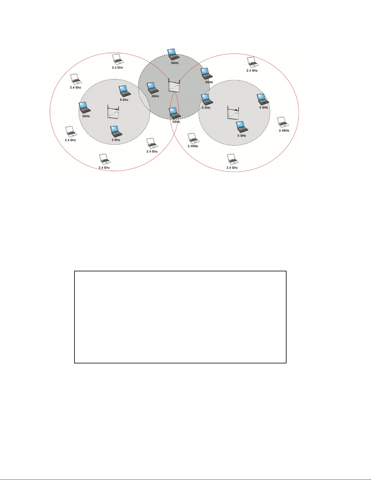
Figure 1-3 802.11a compared to 802.11b/g Coverage Area
Installation and Initialization
The 520wl is designed to support both 2.4 GHz (IEEE 802.11b), 2.4 GHz (IEEE 802.11g), and 5 GHz (IEEE 802.11a)
AP Cards. The HP ProCurve Wireless 802.11a Access Point Kit 160wl has an antenna adapter which snaps into place
on the existing wall mounting bracket. Because of the antenna adapter, only one 160wl card can be installed in the AP.
The second slot can be populated with an HP ProCurve Wireless Access Point card 150wl (802.11b), or 170wl
(802.11g).
Caution: Exposure to Radio Frequency Radiation.
To comply with the FCC RF exposure compliance requirements the following
antenna installation and device operating configurations must be satisfied:
a. For configurations using the integral antenna the separation distance
between the antenna(s) and any person’s body (including hands, wrists,
feet, and ankles) must be at least 2.5 cm (1 inch).
b. For configurations using an approved external antenna the separation
distance between the antenna and any person’s body (including hands,
wrists, feet, and ankles) must be at least 20 cm (8 inches).
The transmitter shall not be collocated with other transmitters or
antennas.
1-8
Page 27

Getting Started
In This Chapter
• Prerequisites
• Product Package
• System Requirements
• Hardware Installation
• Hardware Installation
• Initialization
• Download the Latest Software
• Additional Hardware Features
Prerequisites
Before installing an AP, you need to gather certain network information. The following section identifies the information
you need.
2
Network Name (SSID of the wireless cards) You must assign the Access Point a Network Name before wireless users can
AP’s IP Address If you do not have a DHCP server on your network, then you need to assign the
HTTP Password Each Access Point requires a read/write password to access the web interface. The default
CLI Password Each Access Point requires a read/write password to access the CLI interface. The default
SNMP Read Password Each Access Point requires a password to allow get requests from an SNMP manager.
SNMP Read-Write Password Each Access Point requires a password to allow get and set requests from an SNMP
SNMPv3 Authentication Password If Secure Management is enabled, each Access Point requires a password for sending
SNMPv3 Privacy Password If Secure Management is enabled, each Access Point requires a password when sending
Security Settings You need to determine what security features you will enable on the Access Point.
Authentication Method A primary authentication server may be configured; a back-up authentication server is
Authentication Server Shared Secret This is a password shared between the Access Point and the RADIUS authentication
Authentication Server Authentication Port This is a port number (default is 1812) and is typically provided by the network
Client IP Address Pool Allocation Scheme The Access Point can automatically provide IP addresses to clients as they sign on. The
DNS Server IP Address The network administrator typically provides this IP Address.
communicate with it. The clients also need the same Network Name. This is not the same
as the System Name, which applies only to the Access Point. The network administrator
typically provides the Network Name.
Access Point an IP address that is valid on your network.
password is “public”.
password is “public”.
The default password is “public”.
manager. The default password is “public”.
authenticated SNMPv3 messages. The default password is “public”.
encrypted SNMPv3 data. The default password is “public”.
optional. The network administrator typically provides this information.
server (so both passwords must be the same), and is typically provided by the network
administrator.
administrator.
network administrator typically provides the IP Pool range.
2-1
Page 28

Getting Started
Product Package
Each AP comes with the following:
• One mounting plate
• Mounting hardware
• Metal faceplate for APs mounted in a plenum environment
• AP cover
• Processor module
• Power supply
• AC power cord
• One Installation CD-ROM that contains the following:
– Software Installation Wizard
– ScanTool
– TFTP software
– HTML Help
– This user’s guide in PDF format
• One Unit Installation Quick Start Guide - foldout
If any of these items are missing or damaged, contact your reseller or see the support document that came with your
AP for contact information.
AP Cards
APs can be fitted with different radio type AP Cards. AP Cards are available for 802.11a, 802.11b, and 802.11g.
System Requirements
To begin using an AP, you must have the following minimum requirements:
• A 10Base-T Ethernet or 100Base-TX Fast Ethernet switch or hub.
• At least one radio card designed for the AP: an HP ProCurve Wireless 802.11a Access Point Kit 160wl, 802.11b
Access Point card 150wl, or 802.11g Access Point card 170wl.
• At least one of the following IEEE 802.11-compliant devices:
– An 802.11a client device if you have an HP ProCurve Wireless 802.11a Access Point Kit 160wl
– An 802.11b or 802.11g client device if you have an HP ProCurve Wireless Access Point card 150wl (802.11b)
or 170wl (802.11g)
• A computer that is connected to the same IP network as the AP and has one of the following Web browsers
installed:
– Microsoft Internet Explorer 6 with Service Pack 1 or later and patch Q323308
– Netscape 6.1 or later
(The computer is required to configure the AP using the HTTP interface.)
2-2
Page 29

Getting Started
Hardware Installation
Follow these steps to install your AP:
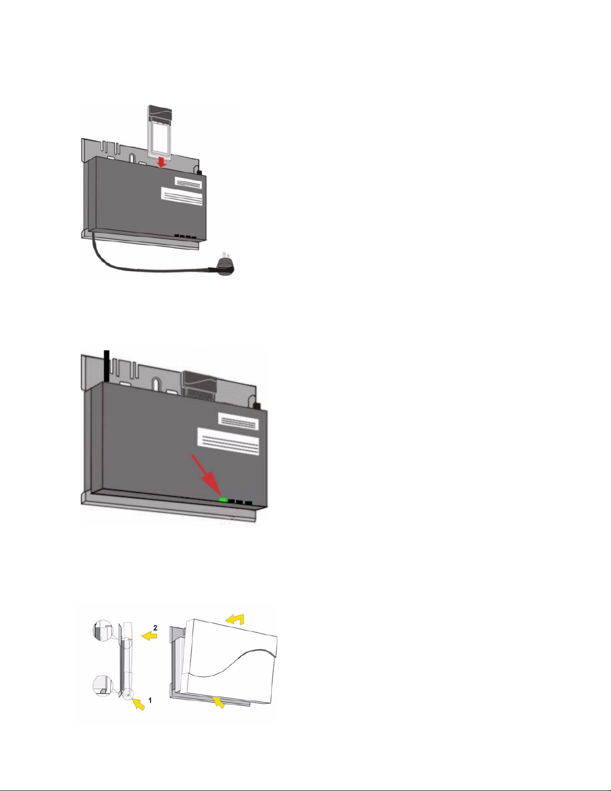
1. Clip the power supply into the mounting bracket.
2. Plug the AC power cord into the power supply.
Figure 2-1 Install the power supply
3. Slide the AP module onto the mounting bracket. Ensure it is properly seated. It mounts over the power supply.
4. Plug the DC connector from the power supply into the top of the AP module.
Figure 2-2 Insert module in mounting bracket and attach power connector
2-3
Page 30
Getting Started
Figure 2-3 Slide an AP Card into the AP
5. Slide an AP Card (not included in the kit) into slot A or B of the AP.
6. Connect the unit to a power source, such as a wall outlet.
7. Wait for the power LED to turn green before proceeding.
Figure 2-4 Power LED turns green when the unit is operational
8. Conduct a Site Survey to determine the best location for your device.
9. Once you have chosen a final location for your unit, mount the bracket and the processor module and place the
cover onto the unit as shown.
Figure 2-5 Final Installation with Cover
2-4
Page 31

Getting Started
10. Connect one end of an Ethernet cable to the AP's Ethernet port. The other end of the cable should not be
connected to any other device until after the installation is complete.
• Use a straight-through Ethernet cable to connect the AP to a hub, switch, or patch panel.
• Use a cross-over Ethernet cable to connect to a single computer.
11. Configure and test the unit. See Initialization for details.
12. Download the latest software to the unit, if necessary. HP provides access point software updates through the HP
ProCurve website at http://www.hp.com/go/hpprocurve. See Download the Latest Software for details.
2-5
Page 32

Getting Started
Initialization
HP provides two tools to simplify the initialization and configuration of an AP:
• ScanTool
• Setup Wizard
ScanTool is included on the Installation CD; the Setup Wizard launches automatically the first time you access the
HTTP interface.
NOTE
These initialization instructions describe how to configure an AP over an Ethernet connection using ScanTool
and the HTTP interface. If you want to configure the unit over the serial port, see
Serial Port for information on how to access the CLI over a serial connection and Command Line Interface
(CLI) for a list of supported commands.
ScanTool
ScanTool is a software utility that is included on the 520wl CD and through the HP ProCurve website at
http://www.hp.com/go/hpprocurve. ScanTool allows you to find the IP address of an Access Point by referencing the
MAC address in a Scan List, or to assign an IP address if one has not been assigned.
The tool automatically detects the Access Points installed on your network, regardless of IP address, and lets you
configure each unit’s IP settings. In addition, you can use ScanTool to download new software to an AP that does not
have a valid software image installed (see
To access the HTTP interface and configure the AP, the AP must be assigned an IP address that is valid on its
Ethernet network. By default, the AP is configured to obtain an IP address automatically from a network Dynamic Host
Configuration Protocol (DHCP) server during boot-up. If your network contains a DHCP server, you can run ScanTool
to find out what IP address the AP has been assigned. If your network does not contain a DHCP server, the
Access Point’s IP address defaults to 10.0.0.1. In this case, you can use ScanTool to assign the AP a static IP address
that is valid on your network.
Client Connection Problems).
Setting IP Address using
ScanTool Instructions
Follow these steps to install ScanTool, initialize the Access Point, and perform initial configuration:
1. Locate the unit’s Ethernet MAC address and write it down for future reference. The MAC address is printed on the
product label. Each unit has a unique MAC address, which is assigned at the factory.
2. Confirm that the AP is connected to the same LAN subnet as the computer that you will use to configure the AP.
3. Power up, reboot, or reset the AP.
– Result: The unit requests an IP Address from the network DHCP server.
4. Insert the Installation CD into the CD-ROM drive of the computer that you will use to configure the AP.
– Result: The installation program will launch automatically.
5. Follow the on-screen instructions to install the Access Point software and documentation.
NOTE
The Installation program supports the following operating systems:
• Windows 98SE
• Windows 2000
• Windows NT
• Windows ME
• Windows XP
6. After the software has been installed, double-click the ScanTool icon on the Windows desktop to launch the
program (if the program is not already running).
– Result: ScanTool scans the subnet and displays all detected Access Points. The ScanTool’s Scan List screen
appears, as shown in the following example.
2-6
Page 33

Getting Started
NOTE
If your computer has more than one network adapter installed, you will be prompted to select the adapter that
you want ScanTool to use before the Scan List appears. If prompted, select an adapter and click OK. You can
change your adapter setting at any time by clicking the Select Adapter button on the Scan List screen. Note
that the ScanTool Network Adapter Selection screen will not appear if your computer only has one network
adapter installed.
Figure 2-6 Scan List
7. Locate the MAC address of the AP you want to initialize within the Scan List.
NOTE
If your Access Point does not show up in the Scan List, click the Rescan button to update the display. If the
unit still does not appear in the list, see
may take up to five minutes for the unit to appear in the Scan List.
8. Do one of the following:
• If the AP has been assigned an IP address by a DHCP server on the network, write down the IP address and
click Cancel to close ScanTool. Proceed to
using this IP address.
• If the AP has not been assigned an IP address (in other words, the unit is using its default IP address,
10.0.0.1), follow these steps to assign it a static IP address that is valid on your network:
1. Highlight the entry for the AP you want to configure.
2. Click the Change button.
— Result: the Change screen appears.
Troubleshooting for suggestions. After rebooting an Access Point, it
Setup Wizard for information on how to access the HTTP interface
Figure 2-7 Scan Tool Change Screen
2-7
Page 34

Getting Started
3. Set IP Address Type to Static.
4. Enter a static IP Address for the AP in the field provided. You must assign the unit a unique address that
is valid on your IP subnet. Contact your network administrator if you need assistance selecting an IP
address for the unit.
5. Enter your network’s Subnet Mask in the field provided.
6. Enter your network’s Gateway IP Address in the field provided.
7. Enter the SNMP Read/Write password in the Read/Write Password field (for new units, the default
SNMP Read/Write password is “public”).
NOTE
The TFTP Server IP Address and Image File Name fields are only available if ScanTool detects that the AP
does not have a valid software image installed. See Client Connection Problems.
8. Click OK to save your changes.
— Result: The Access Point will reboot automatically and any changes you made will take effect.
9. When prompted, click OK a second time to return to the Scan List screen.
10. Click Cancel to close the ScanTool.
11. Proceed to Setup Wizard for information on how to access the HTTP interface.
Logging into the HTTP Interface
Once the AP has a valid IP Address and an Ethernet connection, you may use your web browser to monitor network
statistics.
The Command Line Interface (CLI) also provides a method for viewing network statistics using Telnet or a serial
connection. This section covers only use of the HTTP interface. For more information about viewing network statistics
with the CLI, refer to
Follow these steps to monitor an AP’s operating statistics using the HTTP interface:
1. Open a Web browser on a network computer.
Command Line Interface (CLI).
NOTE
The HTTP interface supports the following Web browser:
• Microsoft Internet Explorer 6 with Service Pack 1 or later
• Netscape 6.1 or later
2. If necessary, disable the Internet proxy settings. For Internet Explorer users, follow these steps:
– Select Tools > Internet Options....
– Click the Connections tab.
– Click LAN Settings....
– If necessary, remove the check mark from the Use a proxy server box.
– Click OK twice to save your changes and return to Internet Explorer.
3. Enter the Access Point’s IP address in the browser’s Address field and press Enter.
– Result: The AP Enter Network Password screen appears.
4. Enter the HTTP password in the Password field and click OK. Leave the User Name field blank. (By default, the
HTTP password is “public”).
– Result: The System Status screen appears.
2-8
Page 35

Getting Started
Figure 2-8 Enter Network Password Screen
Setup Wizard
The first time you connect to an AP’s HTTP interface, the Setup Wizard launches automatically. The Setup Wizard
provides step-by-step instructions for how to configure the Access Point’s basic operating parameter, such as Network
Name, IP parameters, system parameters, and management passwords.
Setup Wizard Instructions
The first time you logon to the AP HTTP interface, the Setup Wizard launches. Follow these steps to access the
Access Point’s HTTP interface and launch the Setup Wizard:
Figure 2-9 Setup Wizard
5. Click Setup Wizard to begin. If you want to configure the AP without using the Setup Wizard, click Exit and see
Advanced Configuration.
The Setup Wizard supports the following navigation options:
• Save & Next Button: Each Setup Wizard screen has a Save & Next button. Click this button to submit any
changes you made to the unit’s parameters and continue to the next page. The instructions below describe
how to navigate the Setup Wizard using the Save & Next buttons.
2-9
Page 36

Getting Started
• Navigation Panel: The Setup Wizard provides a navigation panel on the left-hand side of the screen. Click
the link that corresponds to the parameters you want to configure to be taken to that particular configuration
screen. Note that clicking a link in the navigation panel will not submit any changes you made to the unit’s
configuration on the current page.
• Exit: The navigation panel also includes an Exit option. Click this link to close the Setup Wizard at any time.
CAUTION
!
If you exit from the Setup Wizard, any changes you submitted (by clicking the Save & Next button) up to that
point will be saved to the unit but will not take effect until it is rebooted.
6. Configure the System Configuration settings and click Save & Next. See System for more information.
7. Configure the Access Point’s Basic IP address settings, if necessary, and click Save & Next. See Basic IP
Parameters for more information.
8. Assign the AP new passwords to prevent unauthorized access and click Save & Next. Each management
interface has its own password:
— SNMP Read Password
— SNMP Read-Write Password
— SNMPv3 Authentication Password
— SNMPv3 Privacy Password
— CLI Password
— HTTP (Web) Password
By default, each of these passwords is set to “public”. See Passwords for more information.
9. Configure the basic wireless interface settings and click Save & Next.
• The following options are available for an 802.11a AP:
— Network Name (SSID): Enter a Network Name (between 2 and 31 characters long) for the wireless
network. You must configure each wireless client to use this name as well.
— Auto Channel Select: By default, the AP scans the area for other Access Points and selects the best
available communication channel, either a free channel (if available) or the channel with the least amount
of interference. Remove the check mark to disable this option. Note that you cannot disable Auto Channel
Select for 802.11a products in Europe (see
— Frequency Channel: When Auto Channel Select is enabled, this field is read-only and displays the
Access Point’s current operating channel. When Auto Channel Select is disabled, you can specify the
Access Point’s channel. If you decide to manually set the unit’s channel, ensure that nearby devices do
not use the same frequency. Available Channels vary based on regulatory domain. See
Frequencies. Note that you cannot manually set the channel for 802.11a products in Europe (see
Dynamic Frequency Selection (DFS) for details).
— Transmit Rate: Use the drop-down menu to select a specific transmit rate for the AP. Choose between 6,
9, 12, 18, 24, 36, 48, 54 Mbits/s, and Auto Fallback. The Auto Fallback feature allows the AP to select the
best transmit rate based on the cell size.
— WEP Encryption: Place a check mark in the box provided to enable WEP encryption. See WEP
Encryption for more information.
— Set Encryption Key 1: If you enabled Encryption, configure an Encryption Key. This key is used to
encrypt and decrypt data between the AP and its wireless clients. Enter the number of characters that
correspond to the desired key size, as described below:
— Enter 10 hexadecimal characters (0-9 and A-F) or 5 ASCII characters (see ASCII Character Chart) to
use 64-bit encryption.
— Enter 26 hexadecimal characters or 13 ASCII characters to use 128-bit encryption.
— Enter 32 hexadecimal characters or 16 ASCII characters to use 152-bit encryption.
• The following options are available for an 802.11b AP:
— Network Name (SSID): Enter a Network Name (between 2 and 31 characters long) for the wireless
network. You must configure each wireless client to use this name as well.
— Auto Channel Select: By default, the AP scans the area for other Access Points and selects the best
available communication channel, either a free channel (if available) or the channel with the least amount
of interference. Remove the check mark to disable this option. If you are setting up a Wireless Distribution
System (WDS), it must be disabled. See
Dynamic Frequency Selection (DFS) for details).
802.11a Channel
Wireless Distribution System (WDS) for more information.
2-10
Page 37

Getting Started
— Frequency Channel: When Auto Channel Select is enabled, this field is read-only and displays the
Access Point’s current operating channel. When Auto Channel Select is disabled, you can specify the
Access Point’s operating channel. If you decide to manually set the unit’s channel, ensure that nearby
devices do not use the same frequency (unless you are setting up a WDS). Available Channels vary
based on regulatory domain. See
— Distance Between APs: Set to Large, Medium, Small, Microcell, or Minicell depending on the site
survey for your system. The distance value is related to the Multicast Rate (described next). In general, a
larger distance between APs means that your clients operate a slower data rates (on average). See
Distance Between APs for more information.
802.11b Channel Frequencies.
2-11
Page 38

Getting Started
— Multicast Rate: Sets the rate at which Multicast messages are sent. This value is related to the Distance
Between APs parameter (described previously). The table below displays the possible Multicast Rates
based on the Distance between APs. See
Distance between APs Multicast Rate
Large 1 and 2 Mbits/sec
Medium 1, 2, and 5.5 Mbits/sec
Small 1, 2, 5.5 and 11 Mbits/sec
Minicell 1, 2, 5.5 and 11 Mbits/sec
Microcell 1, 2, 5.5 and 11 Mbits/sec
— WEP Encryption: Place a check mark in the box provided to enable WEP encryption. See WEP
Encryption for more information.
— Set Encryption Key 1: If you enabled Encryption, configure an Encryption Key. This key is used to
encrypt and decrypt data between the AP and its wireless clients. Enter the number of characters that
correspond to the desired key size, as described below:
— Enter 10 hexadecimal characters (0-9 and A-F) or 5 ASCII characters (see ASCII Character Chart) to
use 64-bit encryption.
— Enter 26 hexadecimal characters (0-9 and A-F) or 13 ASCII characters to use 128-bit encryption.
• The following options are available for an 802.11b/g AP:
— Operational Mode: An 802.11b/g wireless interface can be configured to operate in the following modes:
— 802.11b mode only
— 802.11g mode only
— 802.11g-wifi mode (Although this is a valid option, the .11g AP Card is not Wi-Fi certified.)
— 802.11b/g mode (default)
— Network Name (SSID): Enter a Network Name (between 2 and 31 characters long) for the wireless
network. You must configure each wireless client to use this name as well.
— Auto Channel Select: By default, the AP scans the area for other Access Points and selects the best
available communication channel, either a free channel (if available) or the channel with the least amount
of interference. Remove the check mark to disable this option.
— Frequency Channel: When Auto Channel Select is enabled, this field is read-only and displays the
Access Point’s current operating channel. When Auto Channel Select is disabled, you can specify the
Access Point’s channel. If you decide to manually set the unit’s channel, ensure that nearby devices do
not use the same frequency. Available Channels vary based on regulatory domain. See
Frequencies.
— Transmit Rate: Select a specific transmit rate for the AP. The values available depend on the Operational
Mode. Auto Fallback is the default setting; it allows the AP to select the best transmit rate based on the
cell size.
— For 802.11b only -- Auto Fallback, 1, 2, 5.5, 11 Mbits/sec.
— For 802.11g only -- Auto Fallback, 6, 9, 12, 18, 24, 36, 48, 54 Mbits/sec.
— For 802.11b/g and 802.11g-wifi-- Auto Fallback, 1, 2, 5.5, 6, 9, 11, 12, 18, 24, 36, 48, 54 Mbits/sec.
— WEP Encryption: Place a check mark in the box provided to enable WEP encryption. See WEP
Encryption for more information.
— Set Encryption Key 1: If you enabled Encryption, configure an Encryption Key. This key is used to
encrypt and decrypt data between the AP and its wireless clients. Enter the number of characters that
correspond to the desired key size, as described below:
— Enter 10 hexadecimal characters (0-9 and A-F) or 5 ASCII characters (see ASCII Character Chart) to
use 64-bit encryption.
— Enter 26 hexadecimal characters or 13 ASCII characters to use 128-bit encryption.
— Enter 32 hexadecimal characters or 16 ASCII characters to use 152-bit encryption.
Multicast Rate for more information.
802.11g Channel
NOTE
Additional advanced settings are available in the Wireless Interface Configuration screen. See Wireless
(802.11a), Wireless (802.11b), or Wireless (802.11b/g) for details. See Security for more information on
security features.
2-12
Page 39

Getting Started
10. Review the configuration summary. If you want to make any additional changes, use the navigation panel on the
left-hand side of the screen to return to an earlier screen. After making a change, click Save & Next to save the
change and proceed to the next screen.
11. When finished, click Reboot on the Summary screen to restart the AP and apply your changes.
Download the Latest Software
HP periodically releases updated software for the AP on its Web site at http://www.hp.com/go/hpprocurve. HP
recommends that you check the Web site for the latest updates after you have installed and initialized the unit.
Three types of files can be downloaded to the AP from a TFTP server:
— image (AP software image or kernel)
— config (configuration file)
— bspBl (BSP/Bootloader firmware file)
Setup your TFTP Server
A Trivial File Transfer Protocol (TFTP) server allows you to transfer files across a network. You can upload files from
the AP for backup or copying, and you can download the files for configuration and AP Image upgrades. The TFTP
server software is located on the installation CD-ROM.
NOTE
If a TFTP server is not available in the network, you can perform similar file transfer operations using the
HTTP interface.
After the TFTP server is installed:
• Check to see that TFTP is configured to point to the directory containing the AP Image.
• Make sure you have the proper TFTP server IP address, the proper AP Image file name, and that the TFTP server
is operational.
• Make sure the TFTP server is configured to both Transmit and Receive files, with no automatic shutdown
or time-out.
Download Updates from your TFTP Server using the Web Interface
1. Download the latest software from http://www.hp.com/go/hpprocurve.
2. Copy the latest software updates to your TFTP server.
3. In the Web Interface, click the Commands button and select the Download tab.
4. Enter the IP address of your TFTP server in the field provided.
5. Enter the File Name (including the file extension). Enter the full directory path and file name. If the file is located in
the default TFTP directory, you need enter only the file name.
6. Select the File Type from the drop-down menu (use Img for software updates).
7. Select Download & Reboot from the File Operation drop-down menu.
8. Click OK.
9. The Access Point will reboot automatically when the download is complete.
Download Updates from your TFTP Server using the CLI Interface
1. Download the latest software from http://www.hp.com/go/hpprocurve.
2. Copy the latest software updates to your TFTP server.
3. Open the CLI interface by way of Telnet or a serial connection.
4. Enter the CLI password when prompted.
5. Enter the command: download <tftpaddr> <filename> img
– Result: The download will begin. Be patient while the image is downloaded to the Access Point.
6. When the download is complete, type reboot 0 and press Enter.
NOTE
See Command Line Interface (CLI) for more information.
2-13
Page 40

Getting Started
Additional Hardware Features
• Installing the AP in a Plenum
• LED Indicators
Installing the AP in a Plenum
In an office building, plenum is the space between the structural ceiling and the tile ceiling that is provided to help air
circulate. Many companies also use the plenum to house communication equipment and cables. However, these
products and cables must comply with certain safety requirements, such as Underwriter Labs (UL) Standard 2043:
“Standard for Fire Test for Heat and Visible Smoke Release for Discrete Products and Their Accessories Installed in
Air-Handling Spaces”.
The AP has been certified under UL Standard 2043 and can be installed in the plenum only when the following
conditions apply:
• The unit's plastic cover has been removed.
• The power supply of the Access Point has been removed.
• There are two 802.11b or 11g cards in the cards slots.
OR
• There is one 802.11b card and the other card slot is protected with the metal faceplate provided in your kit.
NOTE
The HP ProCurve Wireless 802.11a Access Point Kit160wl is not approved in accordance with UL-2043 for
use in a plenum. The Access Point using a power supply, should not be plenum mounted. Use Active Ethernet
to power the units mounted in a plenum environment.
Installing/Removing the Metal Faceplate
When using only one card in the AP mounted in a plenum environment, remove the plastic cover. Place the top edge
of the faceplate under the front ridge of the metal enclosure. Snap the faceplate in the empty card slot in the AP.
CAUTION
!
Do not drop the faceplate into the card slot in the AP.
To install a second radio card, the faceplate must be removed. Gently pry the faceplate off using the tab on the
faceplate.
LED Indicators
The AP has four LED indicators, which exhibit the following behavior:
Power Ethernet PC Card A PC Card B Indication
Green Green flash with data
Amber Red Amber Amber Rebooting/Power On Self Test
Amber n/a (not applicable) n/a n/a Missing or bad AP Image if amber
Red Red n/a n/a Power On Self Test (POST) running
n/a n/a Red Red PC Card incompatible on indicated
n/a n/a Red Red PC Card failure on indicated
activity
Green flash
with data activity
Green flash
with data activity
Normal Operation
(POST)
after reboot
interface
interface
Green n/a Amber Amber Indicated interface in Administrative
State
2-14
Page 41

Getting Started
n/a n/a Off Off PC Card not present
Related Topics
The Setup Wizard helps you configure the basic AP settings required to get the unit up and running. The AP supports
many other configuration and management options. The remainder of this user guide describes these options in detail.
–See Advanced Configuration for information on configuration options that are available within the Access Point’s
HTTP interface.
–See Monitor Information for information on the statistics displayed within the Access Point’s HTTP interface.
–See Commands for information on the commands supported by the Access Point’s HTTP interface.
–See Troubleshooting for troubleshooting suggestions.
–See Command Line Interface (CLI) for information on the CLI interface and for a list of CLI commands.
2-15
Page 42

Status Information
System Status
System Status is the first screen to appear each time you connect to the HTTP interface. You can also return to this
screen by clicking the Status button.
3
Figure 3-1 System Status Screen
Each section of the System Status screen provides the following information:
– System Status: This area provides system level information, including the unit’s IP address and contact
information. See
– System Alarms: System traps (if any) appear in this area. Each trap identifies a specific severity level:
Critical, Major, Minor, and Informational. See
System for information on these settings.
Alarms for a list of possible alarms.
3-1
Page 43

Advanced Configuration
In This Chapter
• Configuring the AP Using the HTTP/HTTPS Interface.
• System: Configure specific system information such as system name and contact information.
• Network: Configure IP settings, DNS client, DHCP server, and Link Integrity.
• Interfaces: Configure the Access Point’s interfaces: Wireless and Ethernet. Also describes configuring a Wireless
Distribution System (WDS).
• Management: Configure the Access Point’s management Passwords, IP Access Table, and Services such as
configuring secure or restricted access to the AP by way of SNMPv3, HTTPS, or CLI.
Configuration for Static IP.
• Filtering: Configure Ethernet Protocol filters, Static MAC Address filters, Advanced filters, and Port filters.
• Alarms: Configure the Alarm (SNMP Trap) Groups, the Alarm Host Table, and the Syslog features.
• Bridge: Configure the Spanning Tree Protocol, Storm Threshold protection, Intra BSS traffic, and Packet
Forwarding.
• Security: Configure security features such as MAC Access Control, WPA, WEP Encryption, and 802.1x. Configure
Rogue Access Point Detection (RAD) and define the Scan Interval.
• RADIUS: Configure RADIUS features such as RADIUS Access Control and Accounting.
• VLAN/SSID: Configure VLAN IDs and SSIDs.
Configuring the AP Using the HTTP/HTTPS Interface
Follow these steps to configure an Access Point’s operating settings using the HTTP/HTTPS interface:
1. Open a Web browser on a network computer.
Set up Automatic
4
NOTE
The HTTP interface supports the following Web browser:
• Microsoft Internet Explorer 6 with Service Pack 1 or later
• Netscape 6.1 or later
2. If necessary, disable the Internet proxy settings. For Internet Explorer users, follow these steps:
– Select Tools > Internet Options....
– Click the Connections tab.
– Click LAN Settings....
– If necessary, remove the check mark from the Use a proxy server box.
– Click OK twice to save your changes and return to Internet Explorer.
3. Enter the Access Point’s IP address in the browser’s Address field and press Enter.
– Result: The Enter Network Password screen appears.
4. Enter the HTTP password in the Password field and click OK. Leave the User Name field blank. (By default, the
HTTP password is “public”).
– Result: The System Status screen appears.
4-1
Page 44

Advanced Configuration
Figure 4-1 Enter Network Password Screen
5. Click the Configure button located on the left-hand side of the screen.
Figure 4-2 Configure Main Screen
6. Click the tab that corresponds to the parameter you want to configure. For example, click Network to configure the
Access Point’s TCP/IP settings. The parameters contained in each of the configuration categories are described
later in this chapter.
7. Configure the Access Point’s parameters as necessary. After changing a configuration value, click OK to save the
change.
8. Reboot the Access Point for all of the changes to take effect.
4-2
Page 45

Advanced Configuration
System
You can configure and view the following parameters within the System Configuration screen:
• Name: The name assigned to the AP. Refer to the Dynamic DNS Support and Access Point System Naming
Convention sections for rules on naming the AP.
• Location: The location where the AP is installed.
• Contact Name: The name of the person responsible for the AP.
• Contact Email: The email address of the person responsible for the AP.
• Contact Phone: The telephone number of the person responsible for the AP.
• Object ID: This is a read-only field that displays the Access Point’s MIB definition; this information is useful if you
are managing the AP using SNMP.
• Ethernet MAC Address: This is a read-only field that displays the unique MAC (Media Access Control) address
for the Access Point’s Ethernet interface. The MAC address is assigned at the factory.
• Descriptor: This is a read-only field that reports the Access Point’s name, serial number, current image software
version, and current bootloader software version.
• Up Time: This is a read-only field that displays how long the Access Point has been running since its last reboot.
Dynamic DNS Support
DNS is a distributed database mapping the user readable names and IP addresses (and more) of every registered
system on the Internet. Dynamic DNS is a lightweight mechanism which allows for modification of the DNS data of
host systems whose IP addresses change dynamically. Dynamic DNS is usually used in conjunction with DHCP for
assigning meaningful names to host systems whose IP addresses change dynamically.
Access Points provide DDNS support by adding the host name (option 12) in DHCP Client messages, which is used
by the DHCP server to dynamically update the DNS server.
Access Point System Naming Convention
The Access Point's system name is used as its host name. In order to prevent Access Points with default
configurations from registering similar host names in DNS, the default system name of the Access Point is uniquely
generated. Access Points generate unique system names by appending the last 3 bytes of the Access Point's MAC
address to the default system name.
The system name must be compliant with the encoding rules for host name as per DNS RFC 1123. The DNS host
name encoding rules are:
• Characters have to alphanumeric or hyphen.
• The name cannot start or end with a hyphen.
• The name cannot start with a digit.
• The number of characters has to be 63 or less. (Currently the system name length is limited to 32 bytes).
Image upgrades could cause the system to boot with an older system name format that is not DNS compliant. To
prevent problems with dynamic DNS after an image upgrade, the system name will automatically be converted to a
DNS compliant system name.
The rules of conversion of older system names are:
• If the length is greater than 63 then the string is truncated. (This will not happen since the system name is anyway
limited to 32 bytes)
• All invalid characters at the beginning or end of the string are replaced with the character 'X'.
• All other invalid characters are replaced with hyphens.
4-3
Page 46

Advanced Configuration
Network
The Network category contains three sub-categories.
– IP Configuration
– DHCP Server
– Link Integrity
IP Configuration
You can configure and view the following parameters within the IP Configuration screen:
NOTE
You must reboot the Access Point in order for any changes to the Basic IP or DNS Client parameters take
effect.
Basic IP Parameters
• IP Address Assignment Type: Set this parameter to Dynamic to configure the Access Point as a Dynamic Host
Configuration Protocol (DHCP) client; the Access Point will obtain IP settings from a network DHCP server
automatically during boot-up. If you do not have a DHCP server or if you want to manually configure the
Access Point’s IP settings, set this parameter to Static.
• IP Address: The Access Point’s IP address. When IP Address Assignment Type is set to Dynamic, this field is
read-only and reports the unit’s current IP address. The Access Point will default to 10.0.0.1 if it cannot obtain an
address from a DHCP server.
• Subnet Mask: The Access Point’s subnet mask. When IP Address Assignment Type is set to Dynamic, this field is
read-only and reports the unit’s current subnet mask. The subnet mask will default to 255.0.0.0 if the unit cannot
obtain one from a DHCP server.
• Gateway IP Address: The IP address of the Access Point’s gateway. When IP Address Assignment Type is set to
Dynamic, this field is read-only and reports the IP address of the unit’s gateway. The gateway IP address will
default to 10.0.0.2 if the unit cannot obtain an address from a DHCP server.
DNS Client
If you prefer to use host names to identify network servers rather than IP addresses, you can configure the AP to act
as a Domain Name Service (DNS) client. When this feature is enabled, the Access Point contacts the network’s DNS
server to translate a host name to the appropriate network IP address. You can use this DNS Client functionality to
identify RADIUS servers by host name. See
• Enable DNS Client: Place a check mark in the box provided to enable DNS client functionality. Note that this
option must be enabled before you can configure the other DNS Client parameters.
• DNS Primary Server IP Address: The IP address of the network’s primary DNS server.
• DNS Secondary Server IP Address: The IP address of a second DNS server on the network. The Access Point
will attempt to contact the secondary server if the primary server is unavailable.
• DNS Client Default Domain Name: The default domain name for the Access Point’s network (for example,
“proxim.com”). Contact your network administrator if you need assistance setting this parameter.
RADIUS for details.
Advanced
• Default TTL (Time to Live): Time to Live (TTL) is a field in an IP packet that specifies how long in seconds the
packet can remain active on the network. The Access Point uses the default TTL for packets it generates for which
the transport layer protocol does not specify a TTL value. This parameter supports a range from 0 to 65535. By
default, TTL is 64.
4-4
Page 47

Advanced Configuration
DHCP Server
If your network does not have a DHCP Server, you can configure the AP as a DHCP server to assign dynamic IP
addresses to Ethernet nodes and wireless clients.
CAUTION
!
Make sure there are no other DHCP servers on the network and do not enable the DHCP server without
checking with your network administrator first, as it could bring down the whole network. Also, the AP must be
configured with a static IP address before enabling this feature.
When the DHCP Server functionality is enabled, you can create one or more IP address pools from which to assign
addresses to network devices.
Figure 4-3 DHCP Server Configuration Screen
4-5
Page 48

Advanced Configuration
You can configure and view the following parameters within the DHCP Server Configuration screen:
• Enable DHCP Server: Place a check mark in the box provided to enable DHCP Server functionality.
NOTE
You cannot enable the DHCP Server functionality unless there is at least one IP Pool Table Entry configured.
• Subnet Mask: This field is read-only and reports the Access Point’s current subnet mask. DHCP clients that
receive dynamic addresses from the AP will be assigned this same subnet mask.
• Gateway IP Address: The AP will assign the specified address to its DHCP clients.
• Primary DNS IP Address: The AP will assign the specified address to its DHCP clients.
• Secondary DNS IP Address: The AP will assign the specified address to its DHCP clients.
• Number of IP Pool Table Entries: This is a read-only field that reports the number of IP address pools currently
configured.
• IP Pool Table Entry: This entry specifies a range of IP addresses that the AP can assign to its wireless clients.
Click Add to create a new entry. Click Edit to change an existing entry. Each entry contains the following field:
– Start IP Address
– End IP Address
– Default Lease Time (optional): The default time value for clients to retain the assigned IP address. DHCP
automatically renews IP Addresses without client notification. This parameter supports a range between 0 and
86400 seconds. The default is 86400 seconds.
– Maximum Lease Time (optional): The maximum time value for clients to retain the assigned IP address.
DHCP automatically renews IP Addresses without client notification. This parameter supports a range
between 0 and 86400 seconds. The default is 86400 seconds.
– Comment (optional)
– Status: IP Pools are enabled upon entry in the table. You can also disable or delete entries by changing this
field’s value.
NOTE
You must reboot the Access Point before changes to any of these DHCP server parameters take effect.
Link Integrity
The Link Integrity feature checks the link between the AP and the nodes on the Ethernet backbone. These nodes are
listed by IP address in the Link Integrity IP Address Table. The AP periodically pings the nodes listed within the table.
If the AP loses network connectivity (that is, the ping attempts fail), the AP disables its wireless interface until the
connection is restored. This forces the unit’s wireless clients to switch to another Access Point that still has a network
connection. Note that this feature does not affect WDS links (if applicable).
You can configure and view the following parameters within the Link Integrity Configuration screen:
• Enable Link Integrity: Place a check mark in the box provided to enable Link Integrity.
• Poll Interval (milliseconds): The interval between link integrity checks. Range is 500 - 15000 ms in increments of
500 ms; default is 500 ms.
• Poll Retransmissions: The number of times a poll should be retransmitted before the link is considered down.
Range is 0 to 255; default is 5.
• Target IP Address Entry: This entry specifies the IP address of a host on the network that the AP will periodically
poll to confirm connectivity. The table can hold up to five entries. By default, all five entries are set to 0.0.0.0. Click
Edit to update one or more entries. Each entry contains the following field:
– Target IP Address
– Comment (optional)
– Status: Set this field to Enable to specify that the Access Point should poll this device. You can also disable
an entry by changing this field’s value to Disable.
4-6
Page 49

Advanced Configuration
Figure 4-4 Link Integrity Configuration Screen
Interfaces
From the Interfaces tab, you configure the Access Point’s operational mode, power control settings, wireless interface
settings and Ethernet settings. You may also configure a Wireless Distribution System for AP-to-AP communications.
For the wireless interface configuration, refer to the wireless parameters below that correspond to your radio type.
– Operational Mode
– Wireless (802.11a)
– Wireless (802.11b)
– Wireless (802.11b/g)
– Wireless Distribution System (WDS)
– Ethernet
4-7
Page 50

Advanced Configuration
Operational Mode
You can configure and view the following parameters within the Operational Mode screen.
• Operational Mode: the mode of communication between the wireless clients and the Access Point:
• 802.11b only
• 802.11g only
• 802.11bg
• 802.11a (default)
• 802.11g-wifi (Although this is a valid option, the .11g AP Card is not Wi-Fi certified.)
TX Power Control
The TX Power Control feature lets the user configure the transmit power level of the card in the AP at one of four
levels:
• 100% of the maximum transmit power level of the card
• 50%
• 25%
• 12.5%
NOTE
TX Power Control is only supported on the HP ProCurve Wireless 802.11g AP Card 170wl.
Configuring TX Power Control
1. Click Configure > Interfaces > Operational Mode.
2. Select Enable Transmit Power Control.
3. Select the transmit power level for interface A from the Wireless-A: Transmit Power Level drop-down menu.Select
the transmit power level for interface B from the Wireless-B: Transmit Power Level drop-down menu.
4. Click OK.
4-8
Page 51

Advanced Configuration
Wireless (802.11a)
You can configure and view the following parameters within the Wireless Interface Configuration screen for an
802.11a AP:
NOTE
You must reboot the Access Point before any changes to these parameters take effect.
• Physical Interface Type: For an 802.11a AP, this field reports: “802.11a (OFDM 5 GHz).” OFDM stands for
Orthogonal Frequency Division Multiplexing; this is the name for the radio technology used by 802.11a devices.
• MAC Address: This is a read-only field that displays the unique MAC (Media Access Control) address for the
Access Point’s wireless interface. The MAC address is assigned at the factory.
• Regulatory Domain: Reports the regulatory domain for which the AP is certified. Not all features or channels are
available in all countries. The available regulatory domains include:
— FCC - U.S./Canada, Mexico, and Australia
— ETSI - Europe and the United Kingdom
—MKK: Japan
— SG: Singapore
— ASIA: China, Hong Kong, and South Korea
—TW: Taiwan
• Network Name (SSID): Enter a Network Name (between 2 and 31 characters long) for the wireless network. You
must configure each wireless client to use this name as well.
• Auto Channel Select: The AP scans the area for other Access Points and selects a free or relatively unused
communication channel. This helps prevent interference problems and increases network performance. By default
this feature is enabled. See
802.11a Channel Frequencies for a list of Channels.
NOTE
You cannot disable Auto Channel Select for 802.11a products in Europe (see Dynamic Frequency Selection
(DFS) for details).
• Frequency Channel: When Auto Channel Select is enabled, this field is read-only and displays the Access Point’s
current operating Channel. When Auto Channel Select is disabled, you can specify the Access Point’s channel. If
you decide to manually set the unit’s Channel, ensure that nearby devices do not use the same frequency.
Available Channels vary based on regulatory domain. See
manually set the channel for 802.11a products in Europe (see
• Transmit Rate: Use the drop-down menu to select a specific transmit rate for the AP. Choose between 6, 9, 12,
18, 24, 36, 48, 54 Mbits/s, and Auto Fallback. Auto Fallback is the default setting; it allows the AP unit to select the
best transmit rate based on the cell size.
• DTIM Period: The Deferred Traffic Indicator Map (DTIM) is used with clients that have power management
enabled. DTIM should be left at 1, the default value, if any clients have power management enabled. This
parameter supports a range between 1 and 255.
• RTS/CTS Medium Reservation: This parameter affects message flow control and should not be changed under
normal circumstances. Range is 0 to 2347. When set to a value between 0 and 2347, the Access Point uses the
RTS/CTS mechanism for packets that are the specified size or greater. When set to 2347 (the default setting),
RTS/CTS is disabled. See
• Closed System: Check this box to allow only clients configured with the Access Point’s specific Network Name to
associate with the Access Point. When enabled, a client configured with the Network Name “ANY” cannot connect
to the AP. This option is disabled by default.
RTS/CTS Medium Reservation for more information.
802.11a Channel Frequencies. Note that you cannot
Dynamic Frequency Selection (DFS) for details).
Dynamic Frequency Selection (DFS)
802.11a APs sold in Europe use a technique called Dynamic Frequency Selection (DFS) to automatically select an
operating channel. During boot-up, the AP scans the available frequency and selects a channel that is free of
interference. If the AP subsequently detects interference on its channel, it automatically reboots and selects another
channel that is free of interference.
DFS only applies to 802.11a APs used in Europe (i.e., units whose regulatory domain is set to ETSI). The European
Telecommunications Standard Institute (ETSI) requires that 802.11a devices use DFS to prevent interference with
radar systems and other devices that already occupy the 5 GHz band.
4-9
Page 52

Advanced Configuration
If you are using an 802.11a AP in Europe, keep in mind the following:
• DFS is not a configurable parameter. It is always enabled and cannot be disabled.
• You cannot manually select the device’s operating channel; you must let DFS select the channel.
• You cannot configure the Auto Channel Select option. Within the HTTP interface, this option always appears
enabled.
RTS/CTS Medium Reservation
The 802.11 standard supports optional RTS/CTS communication based on packet size. Without RTS/CTS, a sending
radio listens to see if another radio is already using the medium before transmitting a data packet. If the medium is
free, the sending radio transmits its packet. However, there is no guarantee that another radio is not transmitting a
packet at the same time, causing a collision. This typically occurs when there are hidden nodes (clients that can
communicate with the Access Point but are out of range of each other) in very large cells.
When RTS/CTS occurs, the sending radio first transmits a Request to Send (RTS) packet to confirm that the medium
is clear. When the receiving radio successfully receives the RTS packet, it transmits back a Clear to Send (CTS)
packet to the sending radio. When the sending radio receives the CTS packet, it sends the data packet to the receiving
radio. The RTS and CTS packets contain a reservation time to notify other radios (including hidden nodes) that the
medium is in use for a specified period. This helps to minimize collisions. While RTS/CTS adds overhead to the radio
network, it is particularly useful for large packets that take longer to resend after a collision occurs.
RTS/CTS Medium Reservation is an advanced parameter and supports a range between 0 and 2347 bytes. When set
to 2347 (the default setting), the RTS/CTS mechanism is disabled. When set to 0, the RTS/CTS mechanism is used
for all packets. When set to a value between 0 and 2347, the Access Point uses the RTS/CTS mechanism for packets
that are the specified size or greater. You should not need to enable this parameter for most networks unless you
suspect that the wireless cell contains hidden nodes.
Wireless (802.11b)
You can configure and view the following parameters within the Wireless Interface Configuration screen for an
802.11b AP:
NOTE
You must reboot the Access Point before any changes to these parameters take effect.
• Physical Interface Type: For 802.11b AP, this field reports: “802.11b (DSSS 2.4 GHz).” DSSS stands for Direct
Sequence Spread Spectrum; this is the name for the radio technology used by 802.11b devices.
• MAC Address: This is a read-only field that displays the unique MAC (Media Access Control) address for the
Access Point’s wireless interface. The MAC address is assigned at the factory.
• Regulatory Domain: Reports the regulatory domain for which the AP is certified. Not all features or channels are
available in all countries. The available regulatory domains include:
— FCC - U.S./Canada, Mexico, and Australia
— ETSI - Most of Europe, including the United Kingdom and some Eastern block countries
—MKK - Japan
— IL - Israel
• Network Name (SSID): Enter a Network Name (between 2 and 31 characters long) for the wireless network. You
must configure each wireless client to use this name as well.
• Auto Channel Select: The AP scans the area for other Access Points and selects a free or relatively unused
communication channel. This helps prevent interference problems and increases network performance. By default
this feature is enabled; see
Wireless Distribution System (WDS), it must be disabled. See
information.
• Frequency Channel: When Auto Channel Select is enabled, this field is read-only and displays the Access Point’s
current operating channel. When Auto Channel Select is disabled, you can specify the Access Point’s operating
channel. If you decide to manually set the unit’s channel, ensure that nearby devices do not use the same
frequency (unless you are setting up a WDS). Available Channels vary based on regulatory domain. See
Channel Frequencies.
802.11b Channel Frequencies for a list of Channels. However, if you are setting up a
Wireless Distribution System (WDS) for more
802.11b
4-10
Page 53

Advanced Configuration
• Distance Between APs: Set to Large, Medium, Small, Microcell, or Minicell depending on the site survey for
your system. By default, this parameter is set to Large. The distance value is related to the Multicast Rate
(described next). In general, a larger distance between APs means that your clients operate a slower data rates
(on average). See
• Multicast Rate: Sets the rate at which Multicast messages are sent. This value is related to the Distance Between
APs parameter (described previously). The table below displays the possible Multicast Rates based on the
Distance between APs setting. By default, this parameter is set to 2 Mbits/sec. See
information.
Distance between APs Multicast Rate
Large 1 and 2 Mbits/sec
Medium 1, 2, and 5.5 Mbits/sec
Small 1, 2, 5.5 and 11 Mbits/sec
Minicell 1, 2, 5.5 and 11 Mbits/sec
Microcell 1, 2, 5.5 and 11 Mbits/sec
• DTIM Period: The Deferred Traffic Indicator Map (DTIM) is used with clients that have power management
enabled. DTIM should be left at 1, the default value, if any clients have power management enabled. This
parameter supports a range between 1 and 255.
• RTS/CTS Medium Reservation: This parameter affects message flow control and should not be changed under
normal circumstances. Range is 0 to 2347. When set to a value between 0 and 2347, the Access Point uses the
RTS/CTS mechanism for packets that are the specified size or greater. When set to 2347 (the default setting),
RTS/CTS is disabled. See
• Interference Robustness: Enable this option if other electrical devices in the 2.4 GHz frequency band (such as a
microwave oven or a cordless phone) may be interfering with the wireless signal. The AP will automatically
fragment large packets into multiple smaller packets when interference is detected to increase the likelihood that
the messages will be received in the presence of interference. The receiving radio reassembles the original packet
once all fragments have been received. This option is disabled by default.
• Closed System: Check this box to allow only clients configured with the Access Point’s specific Network Name to
associate with the Access Point. When enabled, a client configured with the Network Name “ANY” cannot connect
to the AP. This option is disabled by default.
• Load Balancing: Enable this option so clients can evaluate which Access Point to associate with, based on
current AP loads. This feature is enabled by default; it helps distribute the wireless load between APs. This feature
is only available when using an HP ProCurve Wireless 802.11b AP Card 150wl. In addition, this feature will only
give information for ORiNOCO/Agere/Lucent based clients.
• Medium Density Distribution: When enabled, the Access Point automatically notifies wireless clients of its
Distance Between APs, Interference Robustness, and RTS/CTS Medium Reservation settings. This feature is
enabled by default and allows clients to automatically adopt the values used by its current Access Point (even if
these values differ from the client’s default values or from the values supported by other Access Points). This
feature is only available when using an HP ProCurve Wireless 802.11b AP Card 150wl. In addition, this feature will
only give information for ORiNOCO/Agere/Lucent based clients.
Distance Between APs for more information.
Multicast Rate for more
RTS/CTS Medium Reservation for more information.
Distance Between APs
Distance Between APs defines how far apart (physically) your AP devices are located, which in turn determines the
size of your cell. Cells of different sizes have different capacities and, therefore, suit different applications. For
instance, a typical office has many stations that require high bandwidth for complex, high-speed data processing. In
contrast, a typical warehouse has a few forklifts requiring low bandwidth for simple transactions. This feature is only
available when using an HP ProCurve Wireless 802.11b AP Card 150wl.
Cell capacities are compared in the following table, which shows that small cells suit most offices and large cells suit
most warehouses:
Small Cell Large Cell
Physically accommodates few stations Physically accommodates many stations
High cell bandwidth per station Lower cell bandwidth per station
High transmit rate Lower transmit rate
4-11
Page 54

Advanced Configuration
Coverage
The number of Access Points in a set area determines the network coverage for that area. A large number of
Access Points covering a small area is a high-density cell. A few Access Points, or even a single unit, covering the
same small area would result in a low-density cell, even though in both cases the actual area did not change — only
the number of Access Points covering the area changed.
In a typical office, a high density area consists of a number of Access Points installed every 20 feet and each
Access Point generates a small radio cell with a diameter of about 10 feet. In contrast, a typical warehouse might have
a low density area consisting of large cells (with a diameter of about 90 feet) and Access Points installed every
200 feet.
Figure 4-5 Low Density vs. Ultra High Density Network
The Distance Between Cells parameter supports five values: Large, Medium, Small, Minicell, and Microcell.
CAUTION
!
The distance between APs should not be approximated. It is calculated by means of a manual Site Survey, in
which an AP is set up and clients are tested throughout the area to determine signal strength and coverage,
and local limits such as physical interference are investigated. From these measurements the appropriate cell
size and density is determined, and the optimum distance between APs is calculated to suit your particular
business requirements. Contact your reseller for information on how to conduct a Site Survey.
Multicast Rate
The multicast rate determines the rate at which broadcast and multicast packets are transmitted by the Access Point to
the wireless network. Stations that are closer to the Access Point can receive multicast packets at a faster data rate
than stations that are farther away from the AP. Therefore, you should set the Multicast Rate based on the size of the
Access Point’s cell. For example, if the Access Point’s cell is very small (that is, Distance Between APs is set to
Microcell), you can expect that all stations should be able to successfully receive multicast packets at 11 MBits/sec so
you can set Multicast Rate to 11 Mbits/sec. However, if the Access Point’s cell is large, you need to accommodate
stations that may not be able to receive multicast packets at the higher rates; in this case, you should set Multicast
Rate to 1 or 2 Mbits/sec.
4-12
Page 55

Advanced Configuration
Figure 4-6 1 Mbits/s and 11 Mbits/s Multicast Rates
NOTE
There is an inter-dependent relationship between the Distance between APs and the Multicast Rate. In
general, larger systems operate at a lower average transmit rate. The variation between Multicast Rate and
Distance Between APs is presented in the following table:
1.0 Mbit/s 2.0 Mbits/s 5.5 Mbits/s 11 Mbits/s
Large yes yes
Medium yes yes yes
Small yes yes yes yes
Minicell yes yes yes yes
Microcell yes yes yes yes
The Distance Between APs must be set before the Multicast Rate, because when you select the Distance
Between APs, the appropriate range of Multicast values automatically populates the drop-down menu. This
feature is only available when using an HP ProCurve Wireless 802.11b AP Card 150wl.
4-13
Page 56

Advanced Configuration
Wireless (802.11b/g)
You can configure the following radio parameters for an 802.11b/g AP:
NOTE
You must reboot the Access Point before any changes to these parameters take effect.
• Operational Mode: An 802.11b/g wireless interface can be configured to operate in the following modes:
– 802.11b mode only: The radio uses the 802.11b standard only.
– 802.11g mode only: The radio is optimized to communicate with 802.11g devices. This setting will provide
the best results if this radio interface will only communicate with 802.11g devices.
– 802.11b/g mode: This is the default mode. Use this mode if you want to support a mix of 802.11b and
802.11g devices.
– 802.11g-wifi: This mode was developed for Wi-Fi compliance testing purposes. It is similar to 802.11g only
mode. (Although this is a valid option, the .11g AP Card is not Wi-Fi certified.)
In general, you should use either 802.11g only mode (if you want to support 802.11g devices only) or 802.11b/g
mode to support a mix of 802.11b and 802.11g devices.
• Physical Interface Type: Depending on the Operational Mode, this field reports:
– For 802.11b mode only: "802.11b (CCK/DSSS 2.4 GHz)"
– For 802.11g and 802.11g-wifi modes: "802.11g (OFDM/DSSS 2.4 GHz)"
– For 802.11b/g mode: "802.11b/g (ERP-CCK/DSSS/OFDM 2.4 GHz)"
OFDM stands for Orthogonal Frequency Division Multiplexing; this is the name for the radio technology used by
802.11a devices. DSSS stands for Direct Sequence Spread Spectrum; this is the name for the radio technology
used by 802.11b devices.
• MAC Address: This is a read-only field that displays the unique MAC (Media Access Control) address for the
Access Point’s wireless interface. The MAC address is assigned at the factory.
• Regulatory Domain: Reports the regulatory domain for which the AP is certified. Not all features or channels are
available in all countries. The available regulatory domains include:
— FCC - U.S./Canada, Mexico, and Australia
— ETSI - Europe, including the United Kingdom, China, and South Korea
—MKK - Japan
— IL - Israel
• Network Name (SSID): Enter a Network Name (between 2 and 31 characters long) for the wireless network. You
must configure each wireless client to use this name as well.
• Auto Channel Select: The AP scans the area for other Access Points and selects a free or relatively unused
communication channel. This helps prevent interference problems and increases network performance. By default
this feature is enabled; see
• Frequency Channel: When Auto Channel Select is enabled, this field is read-only and displays the Access Point’s
current operating channel. When Auto Channel Select is disabled, you can specify the Access Point’s operating
channel. If you decide to manually set the unit’s channel, ensure that nearby devices do not use the same
frequency (unless you are setting up a WDS). Available Channels vary based on regulatory domain. See
Channel Frequencies.
• Transmit Rate: Select a specific transmit rate for the AP. The values available depend on the Operational Mode.
Auto Fallback is the default setting; it allows the AP to select the best transmit rate based on the cell size.
— For 802.11b only -- Auto Fallback, 1, 2, 5.5, 11 Mbits/sec
— For 802.11g only -- Auto Fallback, 6, 9, 12, 18, 24, 36, 48, 54 Mbits/sec
— For 802.11b/g and 802.11g-wifi -- Auto Fallback, 1, 2, 5.5, 6, 9, 11, 12, 18, 24, 36, 48, 54 Mbits/sec
• DTIM Period: The Deferred Traffic Indicator Map (DTIM) is used with clients that have power management
enabled. DTIM should be left at 1, the default value, if any clients have power management enabled. This
parameter supports a range between 1 and 255.
• RTS/CTS Medium Reservation: This parameter affects message flow control and should not be changed under
normal circumstances. Range is 0 to 2347. When set to a value between 0 and 2347, the Access Point uses the
RTS/CTS mechanism for packets that are the specified size or greater. When set to 2347 (the default setting),
RTS/CTS is disabled. See RTS/CTS Medium Reservation for more information.
802.11g Channel Frequencies for a list of Channels.
802.11g
4-14
Page 57

Advanced Configuration
• Closed System: Check this box to allow only clients configured with the Access Point’s specific Network Name to
associate with the Access Point. When enabled, a client configured with the Network Name "ANY” cannot connect
to the AP. This option is disabled by default.
Wireless Distribution System (WDS)
A Wireless Distribution System (WDS) creates a link between two 802.11a, 802.11b, or 802.11b/g APs over their radio
interfaces. This link relays traffic from one AP that does not have Ethernet connectivity to a second AP that has
Ethernet connectivity. WDS allows you to configure up to six (6) point-to-point links between Access Points.
In the WDS Example below, AP 1 and AP 2 communicate over a WDS link (represented by the blue line). This link
provides Client 1 with access to network resources even though AP 1 is not directly connected to the Ethernet
network. Packets destined for or sent by the client are relayed between the Access Points over the WDS link. If 802.1q
VLAN tagged packets travel through a WDS link, tags are maintained for all traffic coming from either the wired or
wireless side of the network.
Figure 4-7 WDS Example
Bridging WDS
Each WDS link is mapped to a logical WDS port on the AP. WDS ports behave like Ethernet ports rather than like
standard wireless interfaces: on a BSS port, an Access Point learns by association and from frames; on a WDS or
Ethernet port, an Access Point learns from frames only. When setting up a WDS, keep in mind the following:
• The WDS link shares the communication bandwidth with the clients. Therefore, while the maximum data rate for
the Access Point’s cell is still 11 Mb for 802.1b and 54Mb for 802.11a and 802.11g, client throughput will decrease
when the WDS link is active.
• If there is no partner MAC address configured in the WDS table, the WDS port remains disabled.
• Each WDS port on a single AP should have a unique partner MAC address. Do not enter the same MAC address
twice in an AP’s WDS port list.
• Each Access Point that is a member of the WDS must have the same Channel setting to communicate with each
other.
• Each Access Point that is a member of the WDS must have the same network domain.
• Each Access Point that is a member of the WDS must have the same WEP Encryption settings. WDS does not
use 802.1x. Therefore, if you want to encrypt the WDS link, you must configure each Access Point to use WEP
encryption (either WEP encryption only or Mixed Mode), and each Access Point must have the same Encryption
Key(s). See
Security.
4-15
Page 58

Advanced Configuration
• If your network does not support spanning tree, be careful to avoid creating network loops between APs. For
example, creating a WDS link between two Access Points connected to the same Ethernet network will create a
network loop (if spanning tree is disabled). For more information, refer to the
WDS Setup Procedure
NOTE
You must disable Auto Channel Select to create a WDS. Each Access Point that is a member of the WDS
must have the same Channel setting to communicate with each other.
To setup a wireless backbone follow the steps below for each AP that you wish to include in the Wireless Distribution
System.
1. Confirm that Auto Channel Select is disabled.
2. Write down the MAC Address of the radio that you wish to include in the Wireless Distribution System.
3. Open the Wireless Interface Configuration screen.
4. Scroll down to the Wireless Distribution System heading.
5. Click the Edit button to update the Wireless Distribution System (WDS) Table.
6. Enter the MAC Address that you wrote down in Step 2 in one of the Partner MAC Address field of the Wireless
Distribution Setup window.
7. Set the Status of the device to Enable.
8. Click OK
9. Reboot the AP.
.
Spanning Tree section.
Figure 4-8 WDS Configuration
NOTE
To set up a Wireless Distribution System (WDS) with 802.1x, set each Access Point’s 802.1x Security Mode to
Mixed and assign each unit in the WDS the same Encryption Key 1. See
Security.
Ethernet
Select the desired speed and transmission mode from the drop-down menu. Half-duplex means that only one side can
transmit at a time and full-duplex allows both sides to transmit. When set to auto-duplex, the AP negotiates with its
switch or hub to automatically select the highest throughput option supported by both sides.
For best results, HP recommends that you configure the Ethernet setting to match the speed and transmission mode
of the device the Access Point is connected to (such as a hub or switch). If in doubt, leave this setting at its default,
auto-speed-auto-duplex. Choose between:
• 10 Mbit/s - half duplex, full duplex, or auto duplex
• 100 Mbit/s - half duplex or full duplex
• auto speed - half duplex or auto duplex
4-16
Page 59

Advanced Configuration
Management
The Management category contains three sub-categories.
– Passwords
– IP Access Table
– Services
Passwords
You can configure the following passwords:
• SNMP Read Password: The password for read access to the AP using SNMP. Enter a password in both the
Password field and the Confirm field. The default password is “public”.
• SNMP Read/Write Password: The password for read and write access to the AP using SNMP. Enter a password
in both the Password field and the Confirm field. The default password is “public”.
• SNMPv3 Authentication Password: The password used when sending authenticated SNMPv3 messages. Enter
a password in both the Password field and the Confirm field. The default password is “public”. Password length is
recommended to be at least 8 characters. Secure Management (Services tab) must be enabled to configure
SNMPv3.
• SNMPv3 Privacy Password: The password used when sending encrypted SNMPv3 data. Enter a password in
both the Password field and the Confirm field. The default password is “public”. Password length is
recommended to be at least 8 characters. Secure Management (Services tab) must be enabled to configure
SNMPv3.
• Telnet (CLI) Password: The password for the CLI interface (by way of serial or Telnet). Enter a password in both
the Password field and the Confirm field. The default password is “public”.
• HTTP (Web) Password: The password for the Web browser HTTP interface. Enter a password in both the
Password field and the Confirm field. The default password is “public”.
NOTE
For security purposes HP recommends changing ALL PASSWORDS from the default “public” immediately, to
restrict access to your network devices to authorized personnel. If you lose or forget your password settings,
you can always perform the
Reset to Factory Default Procedure.
IP Access Table
The Management IP Access table limits in-band management access to the IP addresses or range of IP addresses
specified in the table. This feature applies to all management options (SNMP, HTTP, and Telnet). To configure this
table, click Add and set the following parameters:
• IP Address: Enter the IP Address for the management station.
• IP Mask: Enter a mask that will act as a filter to limit access to a range of IP Addresses based on the IP Address
you already entered.
– The IP mask 255.255.255.255 would authorize the single station defined by the IP Address to configure the
Access Point. The AP would ignore commands from any other IP address. In contrast, the IP mask
255.255.255.0 would allow any device that shares the first three octets of the IP address to configure the AP.
For example, if you enter an IP address of 10.20.30.1 with a 255.255.255.0 subnet mask, any IP address
between 10.20.30.1 and 10.20.30.254 will have access to the AP’s management interfaces.
• Comment: Enter an optional comment, such as the station name.
To edit or delete an entry, click Edit. Edit the information, or select Enable, Disable, or Delete from the Status
pull-down menu.
4-17
Page 60

Advanced Configuration
Services
You can configure the following management services:
NOTE
You must reboot the Access Point if you change the HTTP Port or Telnet Port.
Secure Management
Secure Management allows the use of encrypted and authenticated communication protocols such as SNMPv3, and
Secure Socket Link (SSL), to manage the Access Point.
• Enable Secure Management: Enables the further configuration of HTTPS Access, and SNMPv3. After enabling
Secure Management, you can choose to configure HTTPS (SSL) access on the Services tab, and configure
SNMPv3 passwords on the Passwords tab.
SNMP Settings
• SNMP Interface Bitmask: Configure the interface or interfaces (Ethernet, Wireless, All Interfaces) from which
you will manage the AP by way of SNMP. You can also select Disabled to prevent a user from accessing the AP
by way of SNMP.
HTTP Access
• HTTP Interface Bitmap: Configure the interface or interfaces (Ethernet, Wireless, All Interfaces) from which you
will manage the AP by way of the Web interface. For example, to allow Web configuration by way of the Ethernet
network only, set HTTP Interface Bitmask to Ethernet. You can also select Disabled to prevent a user from
accessing the AP from the Web interface.
• HTTP Port: Configure the HTTP port from which you will manage the AP by way of the Web interface. By default,
the HTTP port is 80.
• Enable HTTP Setup Wizard: The Setup Wizard appears automatically the first time you access the HTTP
interface. If you exited out of the Setup Wizard and want to relaunch it, enable this option, click OK, and then close
your browser or reboot the AP. The Setup Wizard will appear the next time you access the HTTP interface.
4-18
Page 61

Advanced Configuration
Figure 4-9 Management Services Configuration Screen
HTTPS Access (Secure Socket Layer)
The user can access the AP in a secure fashion using Secure Socket Layer (SSL) over port 443. The AP supports
SSLv3 with a 128-bit encryption certificate maintained by the AP for secure communications between the AP and the
HTTP client. All communications are encrypted using the server and the client-side certificate. The AP comes
pre-installed with all required SSL files: default certificate and private key installed.
Configuring Secure Socket Layer (SSL)
After enabling SSL, the only configurable parameter is the SSL passphrase.
If you decide to upload a new certificate and private key (using TFTP or HTTP File Transfer), you need to change the
SSL Certificate Passphrase for the new SSL files.
• Enable HTTPS (Secure Web): Check this box to enable SSL on the AP.
NOTE
You need to reboot the AP after enabling or disabling SSL for the changes to take effect.
• SSL Certificate Passphrase: Specifies the SSL Passphrase to use if Enable HTTPS has been checked. The user
must change the SSL passphrase when uploading a new certificate/private key pair, which will have a
corresponding passphrase.
Accessing the AP through the HTTPS interface
The user should use a SSL intelligent browser to access the AP through the HTTPS interface. After configuring SSL,
access the AP using https:// followed by the AP’s management IP address.
4-19
Page 62

Advanced Configuration
Telnet Configuration Settings
• Telnet Interface Bitmask: Select the interface (Ethernet, Wireless, All Interfaces) from which you can manage
the AP by way of telnet. This parameter can also be used to Disable telnet management.
• Telnet Port: The default port number for Telnet applications is 23. However, you can use this field if you want to
change the Telnet port for security reasons (but your Telnet application also must support the new port number you
select).
• Login Idle Timeout (seconds): Enter the number of seconds the system will wait for a login attempt. The AP
terminates the session when it times out. The range is 1 to 300 seconds; the default is 30 seconds.
• Session Idle Timeout (seconds): Enter the number of seconds the system will wait during a session while there
is no activity. The AP will terminate the session on timeout. The range is 1 to 36000 seconds; the default is 900
seconds.
Serial Configuration Settings
The serial port interface on the AP is enabled at all times. See Setting IP Address using Serial Port for information on
how to access the CLI interface by way of the serial port. You can configure and view following parameters:
– Baud Rate: Select the serial port speed (bits per second). Choose between 2400, 4800, 9600, 19200, 38400, or
57600; the default Baud Rate is 9600.
– Flow Control: Select either None (default) or Xon/Xoff (software controlled) data flow control.
NOTE
To avoid potential problems when communicating with the AP through the serial port, HP recommends that
you leave the Flow Control setting at None (the default value).
• Serial Data Bits: This is a read-only field and displays the number of data bits used in serial communication
(8 data bits by default).
• Serial Parity: This is a read-only field and displays the number of parity bits used in serial communication
(no parity bits by default).
• Serial Stop Bits: This is a read-only field that displays the number of stop bits used in serial communication
(1 stop bit by default).
NOTE
The serial port bit configuration is commonly referred to as 8N1.
4-20
Page 63

Advanced Configuration
Automatic Configuration
The Automatic Configuration feature which allows an AP to be automatically configured by downloading a specific
configuration file from a TFTP server during the boot up process.
Automatic Configuration is disabled by default. The configuration process for Automatic Configuration varies
depending on whether the AP is configured for dynamic or static IP.
When an AP is configured for dynamic IP, the Configuration filename and the TFTP server IP address are contained in
the DHCP response when the AP gets its IP address dynamically from the DHCP server. When configured for static
IP, these parameters are instead configured in the AP interface.
After setting up automatic configuration you must reboot the AP. When the AP reboots it receives the new
configuration information and must reboot one additional time. If Syslog is configured, a Syslog message will appear
indicating the success or failure of the Automatic Configuration.
Set up Automatic Configuration for Static IP
Perform the following procedure to enable and set up Automatic Configuration when you have a static IP address for
the TFTP server.
1. Click Configure > Management > AutoConfig.
The
Automatic Configuration Screen appears.
2. Check Enable Auto Configuration.
3. Enter the Configuration Filename.
4. Enter the IP address of the TFTP server in the TFTP Server Address field.
NOTE
The default filename is “config”. The default TFTP IP address is “10.0.0.2”.
5. Click OK to save the changes.
6. Reboot the AP. When the AP reboots it receives the new configuration information and must reboot one additional
time. If a Syslog server was configured, the following messages can be observed on the Syslog server:
• AutoConfig for Static IP
• TFTP server address and configuration filename
• AutoConfg Successful
4-21
Page 64

Advanced Configuration
Figure 4-10 Automatic Configuration Screen
Set up Automatic Configuration for Dynamic IP
Perform the following procedure to enable and set up Automatic Configuration when you have a dynamic IP address
for the TFTP server by way of DHCP.
The Configuration filename and the TFTP server IP address are contained in the DHCP response when the AP gets its
IP address dynamically from the DHCP server. A Syslog server address is also contained in the DHCP response,
allowing the AP to send Auto Configuration success and failure messages to a Syslog server.
NOTE
The configuration filename and TFTP server IP address are configured only when the AP is configured for
Static IP. If the AP is configured for Dynamic IP these parameters are not used and obtained from DHCP.
1. Click Configure > Management > AutoConfig.
The Automatic Configuration Screen appears.
2. Check Enable Auto Configuration.
When the AP is Configured with Dynamic IP, the DHCP server should be configured with the TFTP Server IP address
("Boot Server Host Name", option 66) and Configuration file ("Bootfile name", option 67) as follows:
3. Select DHCP Server > DHCP Option > Scope.
The DHCP Options: Scope Screen appears.
4-22
Page 65

Advanced Configuration
Figure 4-11 DHCP Options: Setting the Boot Server Host Name
4. Add the Boot Server Hostname and Boot Filename parameters to the Active Options list.
5. Set the value of the Boot Server Hostname Parameter to the hostname or IP Address of the TFTP server. For
example: 11.0.0.7.
Figure 4-12 DHCP Options: Setting the Bootfile Name
6. Set the value of the Bootfile Name parameter to the Configuration filename. For example: AP-Config
7. If using Syslog, set the Log server IP address (option 7, Log Servers).
8. Reboot the AP. When the AP reboots it receives the new configuration information and must reboot one additional
time. If a Syslog server was configured, the following messages can be observed on the Syslog server:
• AutoConfig for Dynamic IP
• TFTP server address and configuration filename
• AutoConfg Successful
4-23
Page 66

Advanced Configuration
Filtering
The Access Point’s Packet Filtering features help control the amount of traffic exchanged between the wired and
wireless networks. There are four sub-categories under the Filtering heading.
– Ethernet Protocol
– Static MAC
– Advanced
– TCP/UDP Port
Ethernet Protocol
The Ethernet Protocol Filter blocks or forwards packets based on the Ethernet protocols they support.
Follow these steps to configure the Ethernet Protocol Filter:
1. Select the interface or interfaces that will implement the filter from the Ethernet Protocol Filtering drop-down
menu.
• Ethernet: Packets are examined at the Ethernet interface
• Wireless: Packets are examined at the Wireless interface
• All Interfaces: Packets are examined at both interfaces
• Disabled: The filter is not used
2. Select the Filter Operation Type.
• If set to Passthru, only the enabled Ethernet Protocols listed in the Filter Table will pass through the bridge.
• If set to Block, the bridge will block enabled Ethernet Protocols listed in the Filter Table.
3. Configure the Ethernet Protocol Filter Table. This table is pre-populated with existing Ethernet Protocol Filters,
however, you may enter additional filters by specifying the appropriate parameters.
• To add an entry, click Add, and then specify the Protocol Number and a Protocol Name.
— Protocol Number: Enter the protocol number. See http://www.iana.org/assignments/ethernet-numbers
for a list of protocol numbers.
— Protocol Name: Enter related information, typically the protocol name.
• To edit or delete an entry, click Edit and change the information, or select Enable, Disable, or Delete from the
Status drop-down menu.
• An entry’s status must be enabled in order for the protocol to be subject to the filter.
Static MAC
The Static MAC Address filter optimizes the performance of a wireless (and wired) network. When this feature is
properly configured, the AP can block traffic between wired devices and wireless devices based on MAC address.
For example, you can set up a Static MAC filter to prevent wireless clients from communicating with a specific server
on the Ethernet network. You can also use this filter to block unnecessary multicast packets from being forwarded to
the wireless network.
NOTE
The Static MAC Filter is an advanced feature. You may find it easier to control wireless traffic by way of other
filtering options, such as Ethernet Protocol Filtering.
Each static MAC entry contains the following fields:
• Wired MAC Address
• Wired Mask
• Wireless MAC Address
• Wireless Mask
• Comment: This field is optional.
Each MAC Address or Mask is comprised of 12 hexadecimal digits (0-9, A-F) that correspond to a 48-bit identifier.
(Each hexadecimal digit represents 4 bits (0 or 1).)
Taken together, a MAC Address/Mask pair specifies an address or a range of MAC addresses that the AP will look for
when examining packets. The AP uses Boolean logic to perform an “AND” operation between the MAC Address and
4-24
Page 67

Advanced Configuration
the Mask at the bit level. However, for most users, you do not need to think in terms of bits. It should be sufficient to
create a filter using only the hexadecimal digits 0 and F in the Mask (where 0 is any value and F is the value specified
in the MAC address). A Mask of 00:00:00:00:00:00 corresponds to all MAC addresses, and a Mask of
FF:FF:FF:FF:FF:FF applies only to the specified MAC Address.
For example, if the MAC Address is 00:20:A6:12:54:C3 and the Mask is FF:FF:FF:00:00:00, the AP will examine the
source and destination addresses of each packet looking for any MAC address starting with 00:20:A6. If the Mask is
FF:FF:FF:FF:FF:FF, the AP will only look for the specific MAC address (in this case, 00:20:A6:12:54:C3).
When creating a filter, you can configure the Wired parameters only, the Wireless parameters only, or both sets of
parameters. Which parameters to configure depends upon the traffic that you want block:
– To prevent all traffic from a specific wired MAC address from being forwarded to the wireless network, configure
only the Wired MAC Address and Wired Mask (leave the Wireless MAC Address and Wireless Mask set to all
zeros).
– To prevent all traffic from a specific wireless MAC address from being forwarded to the wired network, configure
only the Wireless MAC address and Wireless Mask (leave the Wired MAC Address and Wired Mask set to all
zeros).
– To block traffic between a specific wired MAC address and a specific wireless MAC address, configure all four
parameters.
To create an entry, click Add and enter the appropriate MAC addresses and Masks to setup a filter. The entry is
enabled automatically when saved. To edit an entry, click Edit. To disable or remove an entry, click Edit and change
the Status field from Enable to Disable or Delete.
Figure 4-13 Static MAC Configuration Screen
Static MAC Filter Examples
Consider a network that contains a wired server and three wireless clients. The MAC address for each unit is as
follows:
– Wired Server: 00:40:F4:1C:DB:6A
– ireless Client 1: 00:02:2D:51:94:E4
– Wireless Client 2: 00:02:2D:51:32:12
– Wireless Client 3: 00:20:A6:12:4E:38
4-25
Page 68

Advanced Configuration
Prevent Two Specific Devices from Communicating
Configure the following settings to prevent the Wired Server and Wireless Client 1 from communicating:
• Wired MAC Address: 00:40:F4:1C:DB:6A
• Wired Mask: FF:FF:FF:FF:FF:FF
• Wireless MAC Address: 00:02:2D:51:94:E4
• Wireless Mask: FF:FF:FF:FF:FF:FF
Result: Traffic between the Wired Server and Wireless Client 1 is blocked. Wireless Clients 2 and 3 can still
communicate with the Wired Server.
Prevent Multiple Wireless Devices From Communicating With a Single Wired Device
Configure the following settings to prevent Wireless Clients 1 and 2 from communicating with the Wired Server.
• Wired MAC Address: 00:40:F4:1C:DB:6A
• Wired Mask: FF:FF:FF:FF:FF:FF
• Wireless MAC Address: 00:02:2D:51:94:E4
• Wireless Mask: FF:FF:FF:00:00:00
Result: When a logical “AND” is performed on the Wireless MAC Address and Wireless Mask, the result corresponds
to any MAC address beginning with the 00:20:2D prefix. Since Wireless Client 1 and Wireless Client 2 share the same
prefix (00:02:2D), traffic between the Wired Server and Wireless Clients 1 and 2 is blocked. Wireless Client 3 can still
communicate with the Wired Server since it has a different prefix (00:20:A6).
Prevent All Wireless Devices From Communicating With a Single Wired Device
Configure the following settings to prevent all three Wireless Clients from communicating with Wired Server 1.
• Wired MAC Address: 00:40:F4:1C:DB:6A
• Wired Mask: FF:FF:FF:FF:FF:FF
• Wireless MAC Address: 00:00:00:00:00:00
• Wireless Mask: 00:00:00:00:00:00
Result: The Access Point blocks all traffic between Wired Server 1 and all wireless clients.
Prevent A Wireless Device From Communicating With the Wired Network
Configure the following settings to prevent Wireless Client 3 from communicating with any device on the Ethernet.
• Wired MAC Address: 00:00:00:00:00:00
• Wired Mask: 00:00:00:00:00:00
• Wireless MAC Address: 00:20:A6:12:4E:38
• Wireless Mask: FF:FF:FF:FF:FF:FF
Result: The Access Point blocks all traffic between Wireless Client 3 and the Ethernet network.
Prevent Messages Destined for a Specific Multicast Group from Being Forwarded to the Wireless LAN
If there are devices on your Ethernet network that use multicast packets to communicate and these packets are not
required by your wireless clients, you can set up a Static MAC filter to preserve wireless bandwidth. For example, if
routers on your network use a specific multicast address (such as 01:00:5E:00:32:4B) to exchange information, you
can set up a filter to prevent these multicast packets from being forwarded to the wireless network:
• Wired MAC Address: 01:00:5E:00:32:4B
• Wired Mask: FF:FF:FF:FF:FF:FF
• Wireless MAC Address: 00:00:00:00:00:00
• Wireless Mask: 00:00:00:00:00:00
Result: The Access Point does not forward any packets that have a destination address of 01:00:5E:00:32:4B to the
wireless network.
4-26
Page 69

Advanced Configuration
Advanced
You can configure the following advanced filtering options:
• Enable Proxy ARP: Place a check mark in the box provided to allow the Access Point to respond to Address
Resolution Protocol (ARP) requests for wireless clients. When enabled, the AP answers ARP requests for wireless
stations without actually forwarding them to the wireless network. If disabled, the Access Point will bridge ARP
requests for wireless clients to the wireless LAN.
• Enable IP/ARP Filtering: Place a check mark in the box provided to allow IP/ARP filtering based on the IP/ARP
Filtering Address and IP Mask. Leave the box unchecked to prevent filtering. If enabled, you should also configure
the IP/ARP Filtering Address and IP/ARP IP Mask.
– IP/ARP Filtering Address: Enter the Network filtering IP Address.
– IP/ARP IP Mask: Enter the Network Mask IP Address.
The following protocols are listed in the Advanced Filter Table:
• Deny IPX RIP
• Deny IPX SAP
• Deny IPX LSP
• Deny IP Broadcasts
• Deny IP Multicasts
The AP can filter these protocols in the wireless-to-Ethernet direction, the Ethernet-to-wireless direction, or in both
directions. Click Edit and use the Status field to Enable or Disable the filter.
TCP/UDP Port
Port-based filtering enables you to control wireless user access to network services by selectively blocking TCP/UDP
protocols through the AP. A user specifies a Protocol Name, Port Number, Port Type (TCP, UDP, or TCP/UDP), and
filtering interfaces (Wireless only, Ethernet only, all interfaces, or no interfaces) in order to block access to services,
such as Telnet and FTP, and traffic, such as NETBIOS and HTTP.
For example, an AP with the following configuration would discard frames received on its Ethernet interface with a
UDP destination port number of 137, effectively blocking NETBIOS Name Service packets.
Protocol Type
(TCP/UDP)
UDP 137 NETBIOS Name Service Ethernet Enable
Destination
Port Number
Protocol Name Interface Status
(Enable/Disable)
Adding TCP/UDP Port Filters
1. Place a check mark in the box labeled Enable TCP/UDP Port Filtering.
2. Click Add under the TCP/UDP Port Filter Table heading.
3. In the TCP/UDP Port Filter Table
4. Set the destination Port Number (a value between 0 and 65535) to filter. See the IANA Web site at
http://www.iana.org/assignments/port-numbers for a list of assigned port numbers and their descriptions.
5. Set the Port Type for the protocol: TCP, UDP, or both (TCP/UDP).
6. Set the Interface to filter:
• Wireless
• Ethernet
• All interfaces
• No interfaces
7. Click OK.
, enter the Protocol Names to filter.
Editing TCP/UDP Port Filters
1. Click Edit under the TCP/UDP Port Filter Table heading.
2. Make any changes to the Protocol Name or Port Number for a specific entry, if necessary.
3. In the row that defines the port, set the Status to Enable, Disable, or Delete, as appropriate.
4. Select OK
.
4-27
Page 70

Advanced Configuration
Alarms
This category has three sub-categories.
– Groups
– Alarm Host Table
– Syslog
Groups
There are seven alarm groups that can be enabled or disabled by way of the Web interface. Place a check mark in the
box provided to enable a specific group. Remove the check mark from the box to disable the alarms. Alarm
Levels vary.
• Configuration Alarm
Trap Name Description
oriTrapDNSIPNotConfigured This traps is generated when the DNS IP Address has not been configured.
Severity Level: Major
• Security Alarms
Trap Name Description
oriTrapAuthenticationFailure This trap is generated when a client authentication failure occurs. The
authentication failures can range from:
- MAC Access Control Table
- RADIUS MAC Authentication
- 802.1x Authentication specifying the EAP-Type
Severity Level: Major
Severity
oriTrapUnauthorizedManagerDetected This trap is generated when an unauthorized manager has attempted to
view and/or modify parameters.
Severity Level: Major
• Wireless Alarms
Trap Name Description
oriTrapWLCNotPresent When you start the AP, this trap is generated when a wireless
oriTrapWLCFailure This trap is generated when a general failure occurs with the
oriTrapWLCRemoval This trap is generated when the wireless interface/card has been
oriTrapWLCIncompatibleFirmware This trap is generated when the firmware of the wireless
oriTrapWLCVoltageDiscrepancy The dual-radio AP supports 3.3 V and 5 V wireless cards. This
oriTrapWLCIncompatibleVendor This trap is generated when an incompatible wireless vendor card
oriTrapWLCFirmwareDownloadFailure This trap is generated when a failure occurs during the firmware
interface/card is not present in the AP.
Severity Level: Informational
wireless interface/card.
Severity Level: Critical
removed from the device.
Severity Level: Critical
interface/card is incompatible with the AP.
Severity Level: Critical
trap is generated when a wireless interface/card using a different
voltage is inserted in the AP.
Severity Level: Critical
is inserted or present in the AP.
Severity Level: Critical
download process of the wireless interface/card.
Severity Level: Critical
4-28
Page 71

Advanced Configuration
• Operational Alarms
Trap Name Description
oriTrapWatchDogTimerExpired This trap is generated when the software watch dog timer
oriTrapRADIUSServerNotResponding This trap is generated when no response is received from the
oriTrapModuleNotInitialized This trap is generated when a certain software or hardware
expires. This indicates that a problem has occurred with one
or more software modules and the AP will reboot
automatically.
Trap Severity Level: Critical
RADIUS server(s) for authentication requests sent from the
RADIUS client in the AP.
Trap Severity Level: Major
module is not initialized or fails to initialize.
Trap Severity Level: Major
oriTrapDeviceRebooting This trap is generated when the AP is rebooting.
oriTrapTaskSuspended This trap is generated when a software task in the AP is
oriTrapBootPFailed In bootloader mode, this trap is generated when the AP does
oriTrapDHCPFailed In operational mode, this trap is generated when the AP does
Trap Severity Level: Informational
suspended.
Trap Severity Level: Critical
not receive a response from the BootP server. The result is
that the Access Point reverts to its static IP configuration and
you will need to set reset configuration options.
Trap Severity Level: Major
not receive a response from the DHCP server. The result is
that the Access Point reverts to its static IP configuration and
you will need to set reset configuration options.
Trap Severity Level: Major
• FLASH Memory Alarms
Trap Name Description
oriTrapFlashMemoryEmpty This trap is generated when an error occurs while downloading a file to
oriTrapFlashMemoryCorrupted This trap is generated when an error occurs while downloading a file to
the AP and no data is present in the flash memory.
Severity Level: Informational
the AP and the data in the flash memory is invalid or corrupted.
Severity Level: Critical
• TFTP Alarms
Trap Name Description
oriTrapTFTPFailedOperation This trap is generated when a failure occurs during a TFTP upload
oriTrapTFTPOperationInitiated This trap is generated when a TFTP upload or download operation
oriTrapTFTPOperationCompleted This trap is generated when a TFTP operation is complete (upload
or download operation.
Severity Level: Major
is started.
Severity Level: Informational
or download).
Severity Level: Informational
4-29
Page 72

Advanced Configuration
• Image Alarms
Trap Name Description
oriTrapZeroSizeImage This trap is generated when a zero size image is loaded on the AP.
oriTrapInvalidImage This trap is generated when an invalid image is loaded in the Access Point.
Trap Severity Level: Major
Trap Severity Level: Major
oriTrapImageTooLarge This trap is generated when the image loaded in the AP exceeds the size
oriTrapIncompatibleImage This trap is generated when an incompatible image is loaded in the AP.
limitation of the flash memory.
Trap Severity Level: Major
Trap Severity Level: Major
In addition, the AP supports these standard traps, which are always enabled:
• RFC 1215-Trap
Trap Name Description
coldStart The AP has been turned on or rebooted.
linkUp The AP's Ethernet interface link is up (working).
linkDown The AP's Ethernet interface link is down (not working).
Trap Severity Level: Informational
Trap Severity Level: Informational
Trap Severity Level: Informational
• Bridge MIB (RFC 1493) Alarms
Trap Name Description
newRoot This trap indicates that the AP has become the new root in the Spanning Tree
topologyChange This trap is sent by the AP when any of its configured ports transitions from the
network.
Trap Severity Level: Informational
Learning state to the Forwarding state, or from the Forwarding state to the
Blocking state.
This trap is not sent if a newRoot trap is sent for the same transition.
Trap Severity Level: Informational
All these alarm groups correspond to System Alarms that are displayed in the System Status screen, including the
traps that are sent by the AP to the SNMP managers specified in the Alarm Host Table.
Severity Levels
There are three severity levels for system alarms:
– Critical
– Major
– Informational
Critical alarms will often result in severe disruption in network activity or an automatic reboot of the AP.
Major alarms are usually activated due to a breach in the security of the system. Clients cannot be authenticated or an
attempt at unauthorized access into the AP has been detected.
Informational alarms are there to provide the network administrator with some general information about the activities
the AP is performing.
4-30
Page 73
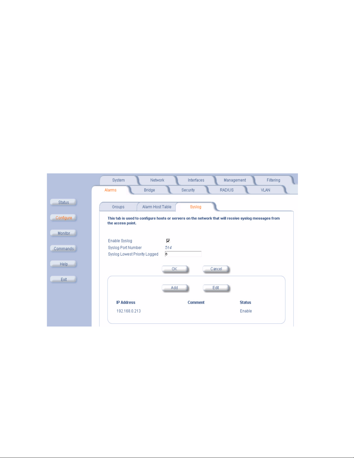
Advanced Configuration
Alarm Host Table
To add an entry and enable the AP to send SNMP trap messages to a Trap Host, click Add, and then specify the IP
Address and Password for the Trap Host.
• IP Address: Enter the Trap Host IP Address.
• Password: Enter the password in the Password field and the Confirm field.
• Comment: Enter an optional comment, such as the alarm (trap) host station name.
To edit or delete an entry, click Edit. Edit the information, or select Enable, Disable, or Delete from the Status
drop-down menu.
Syslog
The Syslog messaging system enables the AP to transmit event messages to a central server for monitoring and
troubleshooting. The AP can send messages to one Syslog server (it cannot send messages to more than one Syslog
server). The access point logs “Session Start (Log-in)” and “Session Stop (Log-out)” events for each wireless client as
an alternative to RADIUS accounting.
See RFC 3164 at http://www.rfc-editor.org for more information on the Syslog standard.
Figure 4-14 Syslog Configuration Screen
Setting Syslog Event Notifications
Syslog Events are logged according to the level of detail specified by the administrator. Logging only urgent system
messages will create a far smaller, more easily read log then a log of every event the system encounters. Determine
which events to log by selecting a priority defined by the following scale:
4-31
Page 74

Advanced Configuration
Event Priority Description
LOG_EMERG 0 system is unusable
LOG_ALERT 1 action must be taken immediately
LOG_CRIT 2 critical conditions
LOG_ERR 3 error conditions
LOG_WARNING 4 warning conditions
LOG_NOTICE 5 normal but significant condition
LOG_INFO 6 informational
LOG_DEBUG 7 debug-level messages
Configuring Syslog Event Notifications
You can configure the following Syslog settings from the HTTP interface:
• Enable Syslog: Place a check mark in the box provided to enable system logging.
• Syslog Port Number: This field is read-only and displays the port number (514) assigned for system logging.
• Syslog Lowest Priority Logged: The AP will send event messages to the Syslog server that correspond to the
selected priority and above. For example, if set to 6, the AP will transmit event messages labeled priority 0 to 6 to
the Syslog server(s). This parameter supports a range between 1 and 7; 6 is the default.
• Syslog Host Table: This table specifies the IP addresses of a network servers that the AP will send Syslog
messages to. Click Add to create a new entry. Click Edit to change an existing entry. Each entry contains the
following field:
– IP Address: Enter the IP Address for the management host.
– Comment: Enter an optional comment such as the host name.
– Status: The entry is enabled automatically when saved (so the Status field is only visible when editing an
entry). You can also disable or delete entries by changing this field’s value.
Bridge
The AP is a bridge between your wired and wireless networking devices. As a bridge, the functions performed by the
AP include:
• MAC address learning
• Forward and filtering decision making
• Spanning Tree protocol used for loop avoidance
Once the AP is connected to your network, it learns which devices are connected to it and records their MAC
addresses in the Learn Table. The table can hold up to 10,000 entries. To view the Learn Table, click on the Monitor
button in the Web interface and select the
The Bridge tab has four sub-categories.
– Spanning Tree
– Storm Threshold
– Intra BSS
– Packet Forwarding
Spanning Tree
A Spanning Tree is used to avoid redundant communication loops in networks with multiple bridging devices. Bridges
do not have any inherent mechanism to avoid loops, because having redundant systems is a necessity in certain
networks. However, redundant systems can cause Broadcast Storms, multiple frame copies, and MAC address table
instability problems.
Complex network structures can create multiple loops within a network. The Spanning Tree configuration blocks
certain ports on AP devices to control the path of communication within the network, avoiding loops and following a
spanning tree structure.
For more information on Spanning Tree protocol, please see Section 8.0 of the IEEE 802.1d standard. The Spanning
Tree configuration options are advanced settings. HP recommends that you leave these parameters at their default
values unless you are familiar with the Spanning Tree protocol.
Learn Table tab.
4-32
Page 75

Advanced Configuration
Storm Threshold
Storm Threshold is an advanced Bridge setup option that you can use to protect the network against data overload by:
• Specifying a maximum number of frames per second as received from a single network device (identified by its
MAC address).
• Specifying an absolute maximum number of messages per port.
The Storm Threshold parameters allow you to specify a set of thresholds for each port of the AP, identifying separate
values for the number of broadcast messages/second and Multicast messages/second.
When the number of frames for a port or identified station exceeds the maximum value per second, the AP will ignore
all subsequent messages issued by the particular network device, or ignore all messages of that type.
– Address Threshold: Enter the maximum allowed number of packets per second.
– Ethernet Threshold:
– Wireless Threshold: Enter the maximum allowed number of packets per second.
Enter the maximum allowed number of packets per second.
Intra BSS
The wireless clients (or subscribers) that associate with a certain AP form the Basic Service Set (BSS) of a network
infrastructure. By default, wireless subscribers in the same BSS can communicate with each other. However, some
administrators (such as wireless public spaces) may wish to block traffic between wireless subscribers that are
associated with the same AP to prevent unauthorized communication and to conserve bandwidth. This feature
enables you to prevent wireless subscribers within a BSS from exchanging traffic.
Although this feature is generally enabled in public access environments, Enterprise LAN administrators use it to
conserve wireless bandwidth by limiting communication between wireless clients. For example, this feature prevents
peer-to-peer file sharing or gaming over the wireless network.
To block Intra BSS traffic, set Intra BSS Traffic Operation to Block.
To allow Intra BSS traffic, set Intra BSS Traffic Operation to Passthru.
Packet Forwarding
The Packet Forwarding feature enables you to redirect traffic generated by wireless clients that are all associated to
the same AP to a single MAC address. This filters wireless traffic without burdening the AP and provides additional
security by limiting potential destinations or by routing the traffic directly to a firewall. You can redirect to a specific port
(Ethernet or WDS) or allow the bridge’s learning process (and the forwarding table entry for the selected MAC
address) to determine the optimal port.
NOTE
The gateway to which traffic will be redirected should be a node on the Ethernet network. It should not be a
wireless client.
Configuring Interfaces for Packet Forwarding
Configure your AP to forward packets by specifying interface port(s) to which packets are redirected and a destination
MAC address.
1. Within the Packet Forwarding Configuration screen, check the box labeled Enable Packet Forwarding.
2. Specify a destination Packet Forwarding MAC Address. The AP will redirect all unicast, multicast, and broadcast
packets received from wireless clients to the address you specify.
3. Select a Packet Forwarding Interface Port from the drop-down menu. You can redirect traffic to:
– Ethernet
– A WDS connection (see Wireless Distribution System (WDS) for details)
– Any (traffic is redirected to a port based on the bridge learning process)
4. Click OK to save your changes.
4-33
Page 76

Advanced Configuration
Security
The AP provides several security features to protect your network from unauthorized access.
• Authentication and Encryption Modes
• MAC Access
• Rogue Access Point Detection (RAD)
Authentication and Encryption Modes
The AP supports the following Security features:
• WEP Encryption: The original encryption technique specified by the IEEE 802.11 standard.
• 802.1x Authentication: An IEEE standard for client authentication.
• Wi-Fi Protected Access (WPA): A new standard that provides improved encryption security over WEP.
WEP Encryption
The IEEE 802.11 standards specify an optional encryption feature, known as Wired Equivalent Privacy or WEP, that is
designed to provide a wireless LAN with a security level equal to what is found on a wired Ethernet network. WEP
encrypts the data portion of each packet exchanged on an 802.11 network using an Encryption Key (also known as a
WEP Key).
When Encryption is enabled, two 802.11 devices must have the same Encryption Keys and both devices must be
configured to use Encryption in order to communicate. If one device is configured to use Encryption but a second
device is not, then the two devices will not communicate, even if both devices have the same Encryption Keys.
• An 802.11b AP supports 64-bit and 128-bit encryption:
– For 64-bit encryption, an encryption key is 10 hexadecimal characters (0-9 and A-F) or 5 ASCII characters
(see
ASCII Character Chart).
– For 128-bit encryption, an encryption key is 26 hexadecimal characters or 13 ASCII characters.
• An 802.11a or 802.11b/g AP supports 64-bit, 128-bit, and 152-bit encryption:
– For 64-bit encryption, an encryption key is 10 hexadecimal characters (0-9 and A-F) or 5 ASCII characters
(see ASCII Character Chart).
– For 128-bit encryption, an encryption key is 26 hexadecimal characters or 13 ASCII characters.
– For 152-bit encryption, an encryption key is 32 hexadecimal characters or 16 ASCII characters.
NOTE
64-bit encryption is sometimes referred to as 40-bit encryption; 128-bit encryption is sometimes referred to as
104-bit encryption.
802.1x Authentication
IEEE 802.1x is a standard that provides a means to authenticate and authorize network devices attached to a LAN
port. A port in the context of IEEE 802.1x is a point of attachment to the LAN, either a physical Ethernet connection or
a wireless link to an Access Point. 802.1x requires a
(EAP) as a standards-based authentication framework, and supports automatic key distribution for enhanced security.
The EAP-based authentication framework can easily be upgraded to keep pace with future EAP types.
Popular EAP types include:
• EAP-Message Digest 5 (MD5): Username/Password-based authentication; does not support automatic key
distribution
• EAP-Transport Layer Security (TLS): Certificate-based authentication (a certificate is required on the server and
each client); supports automatic key distribution
• EAP-Tunneled Transport Layer Security (TTLS): Certificate-based authentication (a certificate is required on the
server; a client’s username/password is tunneled to the server over a secure connection); supports automatic key
distribution
• PEAP - Protected EAP with MS-CHAP v2: Secure username/password-based authentication; supports automatic
key distribution
Different servers support different EAP types and each EAP type provides different features. Refer to the
documentation that came with your RADIUS server to determine which EAP types it supports.
RADIUS server and uses the Extensible Authentication Protocol
4-34
Page 77

Advanced Configuration
NOTE
The AP supports the following EAP types when Authentication Mode is set to 802.1x or WPA: EAP-TLS,
PEAP, and EAP-TTLS. When Authentication Mode is set to Mixed, the AP supports the following EAP types:
EAP-TLS, PEAP, EAP-TLLS, and EAP-MD5 (MD5 does not support automatic key distribution; therefore, if
you choose this method you need to manually configure each client with the network's encryption key).
Authentication Process
There are three main components in the authentication process. The standard refers to them as:
1. supplicant (client PC)
2. authenticator (Access Point)
3. authentication server (RADIUS server)
When using Authentication Mode is set to 802.1x, WPA, or Mixed mode (802.1x and WEP), you need to configure your
RADIUS server for authentication purposes.
Prior to successful authentication, an unauthenticated client PC cannot send any data traffic through the AP device to
other systems on the LAN. The AP inhibits all data traffic from a particular client PC until the client PC is authenticated.
Regardless of its authentication status, a client PC can always exchange 802.1x messages in the clear with the AP
(the client begins encrypting data after it has been authenticated).
Figure 4-15 RADIUS Authentication Illustrated
The AP acts as a pass-through device to facilitate communications between the client PC and the RADIUS server. The
AP (2) and the client (1) exchange 802.1x messages using an EAPOL (EAP Over LAN) protocol (A). Messages sent
from the client station are encapsulated by the AP and transmitted to the RADIUS (3) server using EAP extensions (B).
Upon receiving a reply EAP packet from the RADIUS, the message is typically forwarded to the client, after translating
it back to the EAPOL format. Negotiations take place between the client and the RADIUS server. After the client has
been successfully authenticated, the client receives an Encryption Key from the AP (if the EAP type supports
automatic key distribution). The client uses this key to encrypt data after it has been authenticated.
For 802.11a and 802.11b/g clients that communicate with an AP, each client receives its own unique encryption key;
this is known as Per User Per Session Encryption Keys.
Wi-Fi Protected Access (WPA)
Wi-Fi Protected Access (WPA) is a security standard designed by the Wi-Fi Alliance in conjunction with the Institute of
Electrical and Electronics Engineers (IEEE). WPA is a sub-set of the forthcoming IEEE 802.11i security standard,
currently in draft form. (IEEE 802.11i is also referred to as "WPA2" and will be available in 2004.)
NOTE
For Dual-radio APs: WPA is available for APs an HP ProCurve Wireless 802.11g AP Card 170wl only.
WPA is a replacement for Wired Equivalent Privacy (WEP), the encryption technique specified by the original 802.11
standard. WEP has several vulnerabilities that have been widely publicized. WPA addresses these weaknesses and
provides a stronger security system to protect wireless networks.
4-35
Page 78

Advanced Configuration
WPA provides the following new security measures not available with WEP:
• Improved packet encryption using the Temporal Key Integrity Protocol (TKIP) and the Michael Message Integrity
Check (MIC).
• Per-user, per-session dynamic encryption keys:
– Each client uses a different key to encrypt and decrypt unicast packets exchanged with the AP
– A client's key is different for every session; it changes each time the client associates with an AP
– The AP uses a single global key to encrypt broadcast packets that are sent to all clients simultaneously
– Encryption keys change periodically based on the Re-keying Interval parameter
– WPA uses 128-bit encryption keys
• Dynamic Key distribution
– The AP generates and maintains the keys for its clients
– The AP securely delivers the appropriate keys to its clients
• Client/server mutual authentication
– 802.1x
– Pre-shared key (for networks that do not have an 802.1x solution implemented)
NOTE
For more information on WPA, see the Wi-Fi Alliance Web site at http://www.wi-fi.org.
The AP supports two WPA authentication modes:
• WPA: The AP uses 802.1x to authenticate clients. You should only use an EAP that supports mutual
authentication and session key generation, such as EAP-TLS, EAP-TTLS, and PEAP. See
for details.
• WPA-PSK (Pre-Shared Key): For networks that do not have 802.1x implemented, you can configure the AP to
authenticate clients based on a Pre-Shared Key. This is a shared secret that is manually configured on the AP and
each of its clients. The Pre-Shared Key must be 256 bits long, which is either 64 hexadecimal digits. The AP also
supports a PSK Pass Phrase option to facilitate the creation of the Pre-Shared Key (so a user can enter an
easy-to-remember phrase rather than a string of characters).
802.1x Authentication
Configuring Security Settings
You can configure each wireless interface to operate in one of the following Security modes:
1. No Security: This is the default setting for an AP.
2. Enable WEP Encryption: The AP and clients use the same static WEP keys to encrypt data.
3. Enable 802.1x Security: The AP uses the 802.1x standard to communicate with a RADIUS server and authenticate
clients. The AP generates and distributes dynamic, per user WEP Keys to each client following successful
authentication.
4. Enable Mixed Mode (802.1x and WEP Encryption): The AP uses 802.1x Mode for clients that support 802.1x (and
have an 802.1x supplicant application installed). The AP uses static WEP Encryption for clients that do not use
802.1x.
5. Enable WPA Mode: The AP uses 802.1x to communicate with a RADIUS server and authenticate clients. The AP
generates and distributes dynamic, per user encryption keys (based on the Temporal Key Integrity Protocol (TKIP))
to each client following successful authentication. WPA mode provides message integrity checking to guard
against replay type attacks. This mode is not available for all radio types.
6. Enable WPA-PSK Mode: The AP uses a Pre-shared Key (manually configured on both the AP and the clients) to
authenticate clients. The AP generates and distributes dynamic, per user encryption keys (based on TKIP) to each
client following successful authentication. This mode is for customers who want to use WPA but do not have a
RADIUS server installed on their network. This mode is not available for all radio types.
You configure the AP to use a particular Security mode by setting the Authentication Mode parameter. The following
table summarizes the Authentication Mode options available in the HTTP Interface's Configure > Security >
Authentication screen and describes how each of these options correspond to the six Security Modes listed above:
4-36
Page 79

Advanced Configuration
Authentication Mode Setting Authentication Method Employed Encryption Method Employed
None None None or manually configured Static WEP
802.1x 802.1x Dynamic WEP Keying
Mixed 802.1x or None (depends on a client's
WPA 802.1x Dynamic TKIP Keying
WPA-PSK Manually configured Pre-shared Key Dynamic TKIP Keying
configuration)
settings (from Configure > Security >
Encryption screen)
Dynamic WEP Keying or Static WEP (depends
on client's configuration)
NOTE
Before enabling the 802.1x, Mixed, or WPA mode, the 802.1x server should be configured. Set the encryption
key in Mixed mode after the authentication is set to Mixed mode.
Enable WEP Encryption
Follow these steps to set up WEP encryption on an AP:
1. Click Configure > Security > Authentication.
2. Set Authentication Mode to None (if necessary).
3. Click the Encryption tab.
4. Place a check mark in the box labeled Enable Encryption (WEP).
5. Enter one to four Encryption Keys in the fields provided. Keep in mind the following:
• If entering more than one Key, use the same number of characters for each Key. All Keys need to be the same
Key Size (64, 128, or 152-bit).
• You can enter the Encryption Keys in either hexadecimal or ASCII format.
• You need to configure your wireless clients to use the same Keys in order for the clients and the AP to
communicate.
6. Select the Key that the AP will use to encryption outgoing data from the Encrypt Data Transmissions Using
drop-down menu. By default, this parameter is set to Key 1.
7. Click OK.
Enable 802.1x Security
Follow these steps to enable 802.1x only:
1. Click Configure > Security > Authentication.
2. Set Authentication Mode to 802.1x.
3. Select an Encryption Key Length.
• An 802.11b AP supports 64-bit and 128-bit encryption.
• An 802.11a or 802.11b/g AP supports 64-bit and 128-bit encryption.
4. Enter a Re-keying Interval.
• The Re-keying Interval determines how often a client’s encryption key is changed and can be set to any value
between 60 - 65535 seconds. Rekeying frustrates hacking attempts without taxing system resources. Setting
a fairly frequent rekey value (900 seconds=15 minutes) effectively protects against intrusion without disrupting
network activities.
5. Click OK to save the changes.
6. If you have not already done so, configure the RADIUS authentication settings (see RADIUS Authentication with
802.1x for details).
7. Reboot the Access Point.
4-37
Page 80

Advanced Configuration
Enable Mixed Mode (802.1x and WEP Encryption)
Follow these steps to use both 802.1x and WEP Encryption simultaneously (clients that do not support 802.1x use
WEP Encryption for security purposes):
1. Click Configure > Security > Authentication.
2. Set Authentication Mode to Mixed.
3. Enter a Re-keying Interval.
• The Re-keying Interval determines how often a client’s encryption key is changed and can be set to any value
between 60 - 65535 seconds. Rekeying frustrates hacking attempts without taxing system resources. Setting
a fairly frequent rekey value (900 seconds=15 minutes) effectively protects against intrusion without disrupting
network activities.
4. Click OK to save the changes.
5. Click the Encryption tab.
6. Place a check mark in the box labeled Enable Encryption (WEP).
7. Configure Encryption Key 1 only (i.e., do not configure Keys 2 through 4). Keep in mind the following:
• For 64-bit encryption, an encryption key is 10 hexadecimal characters (0-9 and A-F) or 5 ASCII characters
(see
ASCII Character Chart).
• For 128-bit encryption, an encryption key is 26 hexadecimal characters or 13 ASCII characters.
• You can enter the Encryption Keys in either hexadecimal or ASCII format.
• You need to manually configure your wireless clients that do not support 802.1x to use the same Encryption
Key.
8. Confirm that Key 1 is selected in the Encrypt Data Transmissions Using drop-down menu.
9. Click OK.
10. If you have not already done so, configure the RADIUS authentication settings (see RADIUS Authentication with
802.1x for details).
11. Reboot the Access Point.
802.1x Security and Wireless Distribution Systems (WDS)
Wireless Distribution Systems (WDS) are configured using specific ports on an 802.11a, 802.11b, or 802.11b/g AP. To
use 802.1x with WDS, you need to set the 802.1x Security Mode to Mixed (WEP and 802.1x) and confirm that the APs
communicating in the WDS share the same encryption key (Key 1). See
information.
Wireless Distribution System (WDS) for more
Enable WPA Mode
NOTE
For Dual-radio APs: WPA is available for APs an HP ProCurve Wireless 802.11g AP Card 170wl only.
1. Click Configure > Security > Authentication.
2. Set Authentication Mode to WPA.
3. Enter a Re-keying Interval.
• The Re-keying Interval determines how often a client's encryption key is changed and can be set to any value
between 60 and 65535 seconds. Rekeying frustrates hacking attempts without taxing system resources.
Setting a fairly frequent rekey value (900 seconds=15 minutes) effectively protects against intrusion without
disrupting network activities.
4. Click OK.
5. If you have not already done so, configure the RADIUS authentication settings (see RADIUS Authentication with
802.1x for details).
6. Reboot the Access Point.
Enable WPA-PSK Mode
NOTE
For Dual-radio APs: WPA is available for APs an HP ProCurve Wireless 802.11g AP Card 170wl only.
4-38
Page 81

Advanced Configuration
1. Click Configure > Security > Authentication.
2. Set Authentication Mode to WPA-PSK.
3. Enter a Re-keying Interval.
• The Re-keying Interval determines how often a client's encryption key is changed and can be set to any value
between 60 and 65535 seconds. Rekeying frustrates hacking attempts without taxing system resources.
Setting a fairly frequent rekey value (900 seconds=15 minutes) effectively protects against intrusion without
disrupting network activities.
4. Configure the Pre-Shared Key.
• You must also configure your clients to use this same key.
• Do one of the following:
— Enter 64 hexadecimal digits in the Pre-Shared Key field.
— Enter a phrase in the PSK Pass Phrase field. The AP will automatically generate a Pre-Shared Key
based on the phrase you enter. Enter between 8 and 63 characters; HP recommends using a pass
phrase of at least 13 characters, including both numbers and upper and lower case letters, to ensure that
the generated key cannot be easily deciphered by network infiltrators.
5. Click OK.
6. Reboot the Access Point.
MAC Access
The MAC Access tab allows you to build a list of stations, identified by their MAC addresses, authorized to access the
network through the AP. The list is stored inside each AP within your network. Note that you must reboot the AP for
any changes to the MAC Access Control Table to take effect.
• Enable MAC Access Control: Check this box to enable the Control Table.
• Operation Type: Choose between Passthru and Block. This determines how the stations identified in the MAC
Access Control Table are filtered.
• If set to Passthru, only the addresses listed in the Control Table will pass through the bridge.
• If set to Block, the bridge will block traffic to or from the addresses listed in the Control Table.
• MAC Access Control Table: Click Add to create a new entry. Click Edit to change an existing entry. Each entry
contains the following field:
– MAC Address: Enter the wireless client’s MAC address.
– Comment: Enter an optional comment such as the client’s name.
• Status: The entry is enabled automatically when saved (so the Status field is only visible when editing an
entry). You can also disable or delete entries by changing this field’s value.
NOTE
For larger networks that include multiple Access Points, you may prefer to maintain this list on a centralized
location using the
MAC Access Control by way of RADIUS Authentication.
4-39
Page 82

Advanced Configuration
Figure 4-16 MAC Access Configuration Screen
4-40
Page 83

Advanced Configuration
Rogue Access Point Detection (RAD)
The Rogue AP Detection (RAD) feature provides an additional security level for wireless LAN deployments. RAD
detects unauthorized Access Points in the coverage area. When enabled, the Access Point scans the coverage area
and identifies all active Access Points. Support is available for all versions and operation modes of Access Points. For
example, an 802.11a Access Point identifies all similar Access Points. However, it will not detect Access Points that
are not of this type like 802.11b and 802.11g.
The Rogue AP Scan employs background scanning using low-level 802.11 scanning functions for effective wireless
detection of Access Points in its coverage area with minimal impact on the normal operation of the Access Point.
This RAD feature can be enabled on an Access Point with its HTTP, CLI, or SNMP Interfaces. The scan repetition
duration is configurable. If the Access Point uses directional antennas to provide directional coverage, then the
interface bitmask can be configured to maximize the scanning coverage area. The Access Point will periodically scan
the wireless network and report all the available Access Points within its coverage area using SNMP traps. For
additional reliability the results are stored in the Access Point in a table, which can be queried by way of SNMP. The
BSSID and Channel number of the detected Access Points are provided in the scan results.
The RAD scan is done on a channel list initialized based on the regulatory domain of the device. The RAD Scan then
performs background scanning on all the channels in this channel list using 802.11 MAC scanning functions. It will
either actively scan the network by sending probe requests or passively scan by only listening for beacons. The access
point information is then gathered from the probe responses and beacons.
To minimize traffic disruption and maximize the scanning efficiency, the RAD feature employs an enhanced
background-scanning algorithm and uses the CTS to Self mechanism to keep the clients silent. The scanning
algorithm allows traffic to be serviced between each channel scan. Before start of every scan (except scan on the
working channel) the CTS to self-mechanism is used to set the NAV values of clients to keep them silent during the
scanning period. In addition, the scan repetition duration can also be configured to reduce the frequency of RAD scan
cycles to maximize Access Point performance.
RAD Configuration Requirements
The RAD feature can be configured/monitored by way of the HTTP, CLI, or SNMP management interfaces.
The following management options are provided:
• The RAD feature can be enabled or disabled.
• The repetition interval of RAD can be configured.
• The interface on which RAD can operate can be configured.
• SNMP Traps are sent after completion of a RAD scan cycle and also whenever a new Access Point is detected.
• Additionally, the RAD scan results are maintained in a table that can be queried by way of SNMP.
The system administrator has to enable RAD on the Access Points in the wireless network and also configure the Trap
Host on all these Access Points to the IP address of the management station. The Access Points on detecting a new
Access Point sends a RAD Scan Result Trap to the management station.
Trusted AP
520wl
Rogue AP
520wl
Figure 4-17 Example Rogue AP Detection Deployment
4-41
Page 84

Advanced Configuration
An example network deployment is shown. The Trusted AP has Rogue Access Detection enabled and the trap host is
configured to be the management station. The Trusted AP on detecting the Rogue AP will send a trap to the
management station with the Channel and BSSID of the Rogue Access Point.
Configuring RAD
Perform this procedure to enable RAD and define the Scan Interval and Scan Interface.
The RAD screen also displays the time of the last scan and the number of new access points detected in the last scan.
1. Enable the Security Alarm Group. Select the Security Alarm Group link from the RAD screen. Configure a Trap
Host to receive the list of access points detected during the scan.
2. Click Configure > Security > RAD.
3. Enable RAD by checking Enable Rogue AP Detection.
4. Enter the Scan Interval.
• The Scan Interval specifies the time period in minutes between scans and can be set to any value between 15
and 1440 minutes.
5. Select the Scan Interface as Slot A, Slot B, or both.
6. Click OK.
The results of the RAD scan can be viewed in the Status page in the HTTP interface.
Figure 4-18 Rogue Access Point Detection Screen
4-42
Page 85

Advanced Configuration
RADIUS
The AP communicates with a network’s RADIUS server to provide the following features:
– MAC Access Control by way of RADIUS Authentication
– RADIUS Authentication with 802.1x
– RADIUS Accounting
The network administrator can configure multiple RADIUS Authentication Servers for different Authentication types.
The current available authentication types are EAP/802.1x authentication and MAC-based authentication.You can
configure two separate sets of Primary and Secondary RADIUS Servers for each of the two supported Authentication
types, 802.1x EAP Based authentication and MAC based authentication.
You can configure the AP to communicate with up to six different RADIUS servers:
• Primary Authentication Server (MAC-based authentication)
• Back-up Authentication Server (MAC-based authentication)
• Primary Authentication Server (EAP/802.1x authentication)
• Back-up Authentication Server (EAP/802.1x authentication)
• Primary Accounting Server
• Back-up Accounting Server
NOTE
You must have configured the settings for at least one Authentication server before configuring the settings for
an Accounting server.
The back-up servers are optional, but when configured, the AP will communicate with the back-up server if the primary
server is off-line. After the AP has switched to the backup server, it will periodically check the status of the primary
RADIUS server every five (5) minutes. Once the primary RADIUS server is again online, the AP automatically reverts
from the backup RADIUS server back to the primary RADIUS server. All subsequent requests are then sent to the
primary RADIUS server.
You can view monitoring statistics for each of the configured RADIUS servers.
MAC Access Control by way of RADIUS Authentication
If you want to control wireless access to the network and if your network includes a RADIUS Server, you can store the
list of MAC addresses on the RADIUS server rather than configure each AP individually. From the RADIUS
Authentication tab, you can define the IP Address of the server that contains a central list of MAC Address values that
identify the authorized stations that may access the wireless network. You must specify information for at least the
primary RADIUS server. The back-up RADIUS server is optional.
NOTE
Contact your RADIUS server manufacturer if you have problems configuring the server or have problems
using RADIUS authentication.
Follow these steps to enable RADIUS MAC Access Control:
1. Within the RADIUS Auth screen, place a check mark in the box labeled Enable RADIUS MAC Access Control.
2. Place a check mark in the box labeled Enable Primary RADIUS Authentication Server.
3. If you want to configure a back-up RADIUS server, place a check mark in the box labeled Enable Back-up
RADIUS Authentication Server.
4. Enter the time, in seconds, each client session may be active before being automatically re-authenticated in the
Authorization Lifetime field. This parameter supports a value between 900 and 43200 sec; the default is 900 sec.
5. Select a MAC Address Format Type. This should correspond to the format in which the clients’ 12-digit MAC
addresses are listed within the RADIUS server. Available options include:
• Dash delimited: dash between each pair of digits: xx-yy-zz-aa-bb-cc
• Colon delimited: colon between each pair of digits: xx:yy:zz:aa:bb:cc)
• Single dash delimited: dash between the sixth and seventh digits: xxyyzz-aabbcc
• No delimiters: No characters or spaces between pairs of hexadecimal digits: xxyyzzaabbcc
4-43
Page 86

Advanced Configuration
6. Select a Server Addressing Format type (IP Address or Name).
• If you want to identify RADIUS servers by name, you must configure the AP as a DNS Client. See DNS Client
for details.
7. Enter the server’s IP address or name in the field provided.
8. Enter the port number which the AP and the server will use to communicate. By default, RADIUS servers
communicate on port 1812.
9. Enter the Shared Secret in the Shared Secret and Confirm Shared Secret field. This is a password shared by the
RADIUS server and the AP. The same password must also be configured on the RADIUS server.
10. Enter the maximum time, in seconds, that the AP should wait for the RADIUS server to respond to a request in the
Response Time field. Range is 1-10 seconds; default is 3 seconds.
11. Enter the maximum number of times an authentication request may be retransmitted in the Maximum
Retransmissions field. Range is 1-4; default is 3.
12. If you are configuring a back-up server, repeat Steps 6 through 11 for the back-up server.
13. Click OK to save your changes.
14. Reboot the AP for these changes to take effect.
Figure 4-19 RADIUS MAC-Based Access Control Screen
RADIUS Authentication with 802.1x
You must configure a primary EAP/802.1x Authentication server to use 802.1x security. A back-up server is optional.
NOTE
Problems with RADIUS Server configuration or RADIUS Authentication should be referred to the RADIUS
Server developer.
Follow these steps to enable a RADIUS Authentication server for 802.1x security:
1. Click the RADIUS tab.
2. Click the EAP/802.1x Auth sub-tab.
3. Place a check mark in the box labeled Enable Primary EAP/802.1x Authentication Server.
4-44
Page 87

Advanced Configuration
4. If you want to configure a back-up RADIUS server, place a check mark in the box labeled Enable Backup
EAP/802.1x Authentication Server.
5. Select a Server Addressing Format type (IP Address or Name).
• If you want to identify RADIUS servers by name, you must configure the AP as a DNS Client. See DNS Client
for details.
6. Enter the server’s IP address or name in the field provided.
7. Enter the port number which the AP and the server will use to communicate. By default, RADIUS servers
communicate on port 1812.
8. Enter the Shared Secret in the Shared Secret and Confirm Shared Secret field. This is a password shared by the
RADIUS server and the AP. The same password must also be configured on the RADIUS server.
9. Enter the maximum time, in seconds, that the AP should wait for the RADIUS server to respond to a request in the
Response Time field. Range is 1-10 seconds; default is 3 seconds.
10. Enter the maximum number of times an authentication request may be retransmitted in the Maximum
Retransmissions field. Range is 1-4; default is 3.
11. If you are configuring a back-up server, repeat Steps 7 through 12 for the back-up server.
12. Click OK to save your changes.
13. Reboot the AP device for these changes to take effect.
Figure 4-20 RADIUS EAP/802.1x Authentication Screen
4-45
Page 88

Advanced Configuration
RADIUS Accounting
Using an external RADIUS server, the AP can track and record the length of client sessions on the access point by
sending RADIUS accounting messages per RFC2866. When a wireless client is successfully authenticated, RADIUS
accounting is initiated by sending an “Accounting Start” request to the RADIUS server. When the wireless client
session ends, an “Accounting Stop” request is sent to the RADIUS server.
Session Length
Accounting sessions continue when a client reauthenticates to the same AP. Sessions are terminated when:
• A client disassociates.
• A client does not transmit any data to the AP for a fixed amount of time.
• A client is detected on a different interface.
If the client roams from one AP to another, one session is terminated and a new session is begun.
NOTE
This feature requires RADIUS authentication using MAC Access Control or 802.1x. Wireless clients
configured in the Access Point’s static MAC Access Control list are not tracked.
Configuring RADIUS Accounting
Follow these steps to enable RADIUS accounting on the AP:
1. Within the RADIUS Accounting Configuration screen, place a check mark in the Enable RADIUS Accounting
box to turn on this feature.
2. Place a check mark in the box labeled Enable Primary RADIUS Accounting Server.
3. If you want to configure a back-up RADIUS server, place a check mark in the box labeled Enable Back-up
RADIUS Accounting Server.
4. Enter the session timeout interval in minutes within the Accounting Inactivity Timer field. An accounting session
automatically ends for a client that is idle for the period of time specified. Range is 1-60 minutes; default is
5minutes.
5. Select a Server Addressing Format type (IP Address or Name).
• If you want to identify RADIUS servers by name, you must configure the Access Point as a DNS Client. See
DNS Client for details.
6. Enter the server’s IP address or name in the field provided.
7. Enter the port number which the AP and the server will use to communicate. By default, RADIUS accounting uses
port 1813.
8. Enter the Shared Secret in the Shared Secret and Confirm Shared Secret field. This is a password shared by the
RADIUS server and the AP. The same password must also be configured on the RADIUS server.
9. Enter the maximum time, in seconds, that the AP should wait for the RADIUS server to respond to a request in the
Response Time field. Range is 1-10 seconds; default is 3 seconds.
10. Enter the maximum number of times an authentication request may be retransmitted in the Maximum
Retransmissions field. Range is 1-4; default is 3.
11. If you are configuring a back-up server, repeat Steps 5 through 10 for the back-up server.
12. Click OK to save your changes.
13. Reboot the AP device for these changes to take effect.
4-46
Page 89

Advanced Configuration
Figure 4-21 RADIUS Accounting Server Configuration
VLAN/SSID
The AP allows you to segment wireless networks into multiple sub-networks based on Network Name (SSID) and
VLAN membership.
A Network Name (SSID) identifies a wireless network. Clients associate with Access Points that share its SSID. During
installation, the
setup, the AP can be configured to support up to 16 SSIDs per wireless interface to segment wireless networks based
on VLAN membership.
VLAN Overview
Virtual Local Area Networks (VLANs) are logical groupings of network hosts. Defined by software settings, other VLAN
members or resources appear (to clients) to be on the same physical segment, no matter where they are attached on
the logical LAN or WAN segment. They simplify traffic flow between clients and their frequently-used or restricted
resources.
Setup Wizard prompts you to configure one Network Name for each wireless interface. After initial
NOTE
16 VLAN/SSID pairs are available for APs with an HP ProCurve Wireless 802.11g AP Card 170wl only.
4-47
Page 90

Advanced Configuration
VLANs now extend as far as the reach of the access point signal. Clients can be segmented into wireless
sub-networks by way of SSID and VLAN assignment. A Client can access the network by connecting to an AP
configured to support its assigned SSID/VLAN.
AP devices are fully VLAN-ready; however, by default VLAN support is disabled. Before enabling VLAN support,
certain network settings should be configured, and network resources such as a VLAN-aware switch, a RADIUS
server, and possibly a DHCP server should be available.
Once enabled, VLANs are used to conveniently, efficiently, and easily manage your network in the following ways:
– Manage adds, moves, and changes from a single point of contact
– Define and monitor groups
– Reduce broadcast and multicast traffic to unnecessary destinations
• Improve network performance and reduce latency
– Increase security
• Secure network restricts members to resources on their own VLAN
• Clients roam without compromising security
VLAN tagged data is collected and distributed through an AP's wireless interface(s) based on Network Name (SSID).
An Ethernet port on the access point connects a wireless cell or network to a wired backbone. The access points
communicate across a VLAN-capable switch that analyzes VLAN-tagged packet headers and directs traffic to the
appropriate ports. On the wired network, a RADIUS server authenticates traffic and a DHCP server manages IP
addresses for the VLAN(s). Resources like servers and printers may be present, and a hub may include multiple APs,
extending the network over a larger area.
In this figure, the numbered items correspond to the following components:
1. VLAN-enabled access point
2. VLAN-aware switch (IEEE 802.1Q uplink)
3. AP management by way of wired host (SNMP, Web interface or CLI)
4. DHCP Server
5. RADIUS Server
6. VLAN 1
7. VLAN 2
Figure 4-22 Components of a typical VLAN
4-48
Page 91

Advanced Configuration
VLAN Workgroups and Traffic Management
Access Points that are not VLAN-capable typically transmit broadcast and multicast traffic to all wireless Network
Interface Cards (NICs). This process wastes wireless bandwidth and degrades throughput performance. In
comparison, VLAN-capable AP is designed to efficiently manage delivery of broadcast, multicast, and unicast traffic to
wireless clients.
The AP assigns clients to a VLAN based on a Network Name (SSID). The AP can support up to 16 VLAN/SSID pairs
per radio (based on model type).
NOTE
16 VLAN/SSID pairs are available for APs with an HP ProCurve Wireless 802.11g AP Card 170wl only.
The AP matches packets transmitted or received to a network name with the associated VLAN. Traffic received by a
VLAN is only sent on the wireless interface associated with that same VLAN. This eliminates unnecessary traffic on
the wireless LAN, conserving bandwidth and maximizing throughput.
Traffic Management
In addition to enhancing wireless traffic management, the VLAN-capable AP supports easy assignment of wireless
users to workgroups. In a typical scenario, each user VLAN represents a workgroup; for example, one VLAN could be
used for an EMPLOYEE workgroup and the other, for a GUEST workgroup.
In this scenario, the AP would assign every packet it accepted to a VLAN. Each packet would then be identified as
EMPLOYEE or GUEST, depending on which wireless NIC received it. The AP would insert VLAN headers or “tags”
with identifiers into the packets transmitted on the wired backbone to a network switch.
Finally, the switch would be configured to route packets from the EMPLOYEE workgroup to the appropriate corporate
resources such as printers and servers. Packets from the GUEST workgroup could be restricted to a gateway that
allowed access to only the Internet. A member of the GUEST workgroup could send and receive e-mail and access the
Internet, but would be prevented from accessing servers or hosts on the local corporate network.
Typical User VLAN Configurations
VLANs segment network traffic into workgroups, which enable you to limit broadcast and multicast traffic. Workgroups
enable clients from different VLANs to access different resources using the same network infrastructure. Clients using
the same physical network are limited to those resources available to their workgroup.
The AP can segment users into a maximum of 16 different workgroups (32 if using two cards in a Dual-radio AP)
based on an SSID/VLAN pair (also referred as a VLAN Workgroup or a Sub-network).
NOTE
16 VLAN/SSID pairs are available for APs with an HP ProCurve Wireless 802.11g AP Card 170wl only.
The four primary scenarios for using VLAN workgroups are as follows:
1. VLAN disabled: Your network does not use VLANs, but you can configure the AP to use multiple SSIDs.
2. VLAN enabled, all VLAN Workgroups use the same VLAN ID Tag
3. VLAN enabled, each VLAN workgroup uses a different VLAN ID Tag
4. VLAN enabled, a mixture of Tagged and Untagged workgroups
4-49
Page 92

Advanced Configuration
Configure Multiple VLAN/SSID Pairs
NOTE
You must reboot the AP before any changes to these parameters take effect.
1. Click Configure > VLAN.
2. Place a check mark in the Enable VLAN Protocol box to enable VLAN support.
3. Click the tab for Wireless A or Wireless B (if applicable).
4. Add one or more new SSID/VLAN entries. Follow these steps:
NOTE
16 VLAN/SSID pairs are available for APs with an HP ProCurve Wireless 802.11g AP Card 170wl only.
1. Click Add to create a new SSID/VLAN entry.
2. Enter a Network Name (SSID), between 2 and 31 characters, in the field provided.
3. Enter a VLAN ID in the field provided.
— As defined by the 802.1Q standard, a VLAN ID is a number between 1 and 4094. A value of -1
means that an entry is "untagged". If 802.1q VLAN tagged packets travel through a Wireless
Distribution System (WDS) link, tags are maintained for all traffic coming either from the wired or the
wireless side of the network. .
— You can use the same VLAN ID for all SSIDs if you want all wireless clients to be part of the same
VLAN.
— You can specify a different VLAN ID for each SSID.
— The VLAN ID must match an ID used by your network; contact your network administrator if you need
assistance defining the VLAN IDs.
— You can set the VLAN ID to "-1" or "untagged" if you do not want clients that are using a specific
SSID to be members of a VLAN workgroup.
4. Click OK.
5. Click the back arrow button to return to the previous screen.
5. Click Edit if you want to modify an existing entry. You can also disable or delete an entry from the Edit screen.
6. Click the tab for the second wireless interface (if applicable) and create/modify SSID/VLAN entries as necessary.
7. Reboot the AP.
Typical VLAN Management Configurations
Control Access to the AP
Management access to the AP can easily be secured by making management stations or hosts and the AP itself
members of a common VLAN. Simply configure a non-zero management VLAN ID and enable VLAN to restrict
management of the AP to members of the same VLAN.
CAUTION
!
If a non-zero management VLAN ID is configured then management access to the AP is restricted to wired or
wireless hosts that are members of the same VLAN. Ensure your management platform or host is a member
of the same VLAN before attempting to manage the AP.
1. Click Configure > VLAN.
2. Set the VLAN Management ID to a value between 0 and 4094 (a value of 0 disables VLAN management).
3. Place a check mark in the Enable VLAN Protocol box.
Provide Access to a Wireless Host in the Same Workgroup
The VLAN feature can allow wireless clients to manage the AP. If the VLAN Management ID matches a VLAN User ID,
then those wireless clients who are members of that VLAN will have AP management access.
4-50
Page 93

Advanced Configuration
CAUTION
!
Once a VLAN Management ID is configured and is equivalent to one of the VLAN User IDs on the AP, all
members of that User VLAN will have management access to the AP. Be careful to restrict VLAN membership
to those with legitimate access to the AP.
1. Click Configure > VLAN.
2. Set the VLAN Management ID to use the same VLAN ID as one of the configured SSID/VLAN pairs. See Typical
User VLAN Configurations for details.
3. Place a check mark in the Enable VLAN Protocol box.
Disable VLAN Management
1. Click Configure > VLAN.
2. Remove the check mark from the Enable VLAN Protocol box (to disable all VLAN functionality) or set the VLAN
Management ID to 0 (to disable VLAN Management only).
4-51
Page 94

Monitor Information
In This Chapter
• Version: Provides version information for the Access Point’s system components.
• ICMP: Displays statistics for Internet Control Message Protocol packets sent and received by the AP.
• IP/ARP Table: Displays the AP’s IP Address Resolution table.
• Learn Table: Displays the list of nodes that the AP has learned are on the network.
• IAPP: Provides statistics for the Inter-Access Point Protocol messages sent and received by the AP.
• RADIUS: Provides statistics for the configured primary and backup RADIUS server(s).
• Interfaces: Displays the Access Point’s interface statistics (Wireless and Ethernet).
• Link Test: Evaluates the link with a wireless client.
• Station Statistics: Displays statistics for stations and Wireless Distribution System links.
Accessing Monitor Features
1. Click the Monitor button located on the left-hand side of the screen.
5
Figure 5-1 Monitor Main Screen
2. Click the tab that corresponds to the statistics you want to review. For example, click Learn Table to see the list of
nodes that the AP has discovered on the network.
3. If applicable, click the Refresh button to update the statistics.
5-1
Page 95

Monitor Information
Version
From the HTTP interface, click the Monitor button and select the Version tab. The list displayed provides you with
information that may be pertinent when calling Technical Support. With this information, your Technical Support
representative can verify compatibility issues and make sure the latest software are loaded. This screen displays the
following information for each Access Point component:
• Serial Number: The component’s serial number, if applicable.
• Component Name
• ID: The AP identifies a system component based on its ID. Each component has a unique identifier.
• Va riant: Several variants may exist of the same component (for example, a hardware component may have two
variants, one with more memory than the other).
• Ve rsion: Specifies the component’s version or build number. The Software Image version is the most useful
information on this screen for the typical end user.
Figure 5-2 Version Information Screen
5-2
Page 96

Monitor Information
ICMP
This tab provides statistical information for both received and transmitted messages directed to the AP. Not all ICMP
traffic on the network is counted in the ICMP (Internet Control Message Protocol) statistics.
Figure 5-3 ICMP Monitoring Screen
IP/ARP Table
This tab provides information based on the Address Resolution Protocol (ARP), which relates MAC Address and IP
Addresses.
Figure 5-4 IP/ARP Table
5-3
Page 97

Monitor Information
Learn Table
This tab displays information relating to network bridging. It reports the MAC address for each node that the device has
learned is on the network and the interface on which the node was detected. There can be up 10,000 entries in the
Learn Table.
Figure 5-5 Learn Table
IAPP
This tab displays statistics relating to client handovers and communications between Access Points.
Figure 5-6 IAPP Screen
5-4
Page 98

Monitor Information
RADIUS
This tab provides RADIUS authentication, EAP/802.1x authentication, and accounting information for both the Primary
and Backup RADIUS servers.
NOTE
RADIUS authentication and accounting must be enabled for this information to be valid.
Figure 5-7 RADIUS Monitoring Screen
5-5
Page 99

Monitor Information
Interfaces
This tab displays statistics for the Ethernet and wireless interfaces. The Operational Status can be up, down, or testing.
Figure 5-8 Wireless Interface Monitoring
5-6
Page 100

Monitor Information
Link Test
This tab displays information on the quality of the wireless link to clients and other APs in the Wireless Distribution
System. During a Link Test, the Access Point and the selected device exchange a series of packets to test the strength
of the connection. The devices start by exchanging packets at the 11 Mbits/sec rate but fall back to the slower rates if
necessary.
NOTE
This feature is only available when using an HP ProCurve Wireless 802.11b AP Card 150wl. In addition, this
feature will only give information for ORiNOCO/Agere/Lucent based clients.
Follow these steps to perform a Link Test:
1. Open the Remote Link Test screen.
2. Click Explore.
Result: A list of detected stations will appear. If the list does not appear automatically, click Refresh
.
Figure 5-9 Remote Link Test Screen
3. Select a Station from the list by clicking the circle to the left of the Station’s entry.
4. Click Link Test to start the test.
Result: A new Link Test window opens and displays the following information for the Access Point (referred to as
the Initiator Station) and the wireless client (referred to as the Remote Station):
• Station Name: The Access Point’s System Name or the client’s Windows Networking name.
• MAC Address: The station’s MAC address.
• SNR (dB): The Signal to Noise ratio for the received signal. The displayed value is the running average since
the start of the test and is reported in decibels (dB). Higher numbers correspond to a stronger link. The bar
graph also displays the relative strength of the link (a green bar indicates a strong link, a yellow bar indicates a
fair link, and a red bar indicates a weak link).
• Signal (dBm): The strength of the received signal in dBm (decibels referenced to 1 milliwatt). The displayed
value is the running average since the start of the test and is reported as a negative number. Higher numbers
correspond to a stronger link. For example, -40 dBm corresponds to a stronger signal than -50 dBm. The bar
graph also displays the relative strength of the signal (a longer bar represents a stronger signal).
5-7
 Loading...