

HP ProCurve 408 Installation Manual
ProCurve Switch 408
Installation Guide
www.procurve.com


ProCurve Switch 408
Installation Guide

© Copyright 2001, 2005, 2006, 2007 HewlettPackard Development Company L.P. The
information contained herein is subject to
change without notice.
This document contains proprietary
information, which is protected by
copyright. No part of this document may
be photocopied, reproduced, or
translated into another language without
prior written consent of Hewlett-Packard.
Publication Number
5991-6250
February 2007
Applicable Product
ProCurve Switch 408 (J4097C)
Safety
Before installing and operating this
product, please read the “Installation
Precautions” in chapter 2, “Installing the
Switch 408”, and the safety statements in
appendix C, “Safety and EMC Regulatory
Statements”.
Disclaimer
HEWLETT-PACKARD COMPANY MAKES
NO WARRANTY OF ANY KIND WITH
REGARD TO THIS MATERIAL,
INCLUDING, BUT NOT LIMITED TO,
THE IMPLIED WARRANTIES OF
MERCHANTABILITY AND FITNESS FOR
A PARTICULAR PURPOSE. HewlettPackard shall not be liable for errors
contained herein or for incidental or
consequential damages in connection
with the furnishing, performance, or use
of this material.
The only warranties for HP products and
services are set forth in the express
warranty statements accompanying such
products and services. Nothing herein
should be construed as constituting an
additional warranty. HP shall not be liable
for technical or editorial errors or omissions contained herein.
Hewlett-Packard assumes no responsibility for the use or reliability of its software on equipment that is not furnished
by Hewlett-Packard.
Warranty
See the Customer Support/Warranty
booklet included with the product.
A copy of the specific warranty terms
applicable to your Hewlett-Packard
products and replacement parts can be
obtained from your HP Sales and Service
Office or authorized dealer.
Hewlett-Packard Company
8000 Foothills Boulevard, m/s 5552
Roseville, California 95747-5552
www.procurve.com

Contents
1 Introducing the Switch 408
Front of the Switch . . . . . . . . . . . . . . . . . . . . . . . . . . . . . . . . . 1-2
Network Ports . . . . . . . . . . . . . . . . . . . . . . . . . . . . . . . . . . . . 1-2
LEDs . . . . . . . . . . . . . . . . . . . . . . . . . . . . . . . . . . . . . . . . . . . . 1-3
Back of the Switch . . . . . . . . . . . . . . . . . . . . . . . . . . . . . . . . . . 1-4
Power Connector . . . . . . . . . . . . . . . . . . . . . . . . . . . . . . . . . 1-4
Features . . . . . . . . . . . . . . . . . . . . . . . . . . . . . . . . . . . . . . . . . . . . 1-5
Switch Operation Overview . . . . . . . . . . . . . . . . . . . . . . . . . . 1-5
Address Table Operation . . . . . . . . . . . . . . . . . . . . . . . . . . . 1-5
2 Installing the Switch 408
Included Parts . . . . . . . . . . . . . . . . . . . . . . . . . . . . . . . . . . . . . . 2-1
Japan Power Cord Warning . . . . . . . . . . . . . . . . . . . . . . . . . 2-2
Installation Procedures . . . . . . . . . . . . . . . . . . . . . . . . . . . . . 2-2
Summary . . . . . . . . . . . . . . . . . . . . . . . . . . . . . . . . . . . . . . . . 2-2
Installation Precautions . . . . . . . . . . . . . . . . . . . . . . . . . . . . 2-3
1. Prepare the Installation Site . . . . . . . . . . . . . . . . . . . . . . 2-5
2. Verify the Switch Passes Its Self Test . . . . . . . . . . . . . . 2-6
3. Mount the Switch . . . . . . . . . . . . . . . . . . . . . . . . . . . . . . . 2-8
4. Connect the Switch to a Power Source . . . . . . . . . . . . . 2-9
5. Connect the Network Cables . . . . . . . . . . . . . . . . . . . . . 2-9
Sample Network Topologies . . . . . . . . . . . . . . . . . . . . . . . . 2-10
As a Desktop Switch . . . . . . . . . . . . . . . . . . . . . . . . . . . . . . 2-10
As a Segment Switch . . . . . . . . . . . . . . . . . . . . . . . . . . . . . 2-11
iii

3 Troubleshooting
Basic Troubleshooting Tips . . . . . . . . . . . . . . . . . . . . . . . . . 3-1
Diagnosing With the LEDs . . . . . . . . . . . . . . . . . . . . . . . . . . 3-3
Hardware Diagnostic Tests . . . . . . . . . . . . . . . . . . . . . . . . . 3-5
Testing the Switch by Resetting It . . . . . . . . . . . . . . . . . . 3-5
Testing Twisted-Pair Cabling . . . . . . . . . . . . . . . . . . . . . . . 3-5
Testing End-to-End Network Communications . . . . . . . 3-6
ProCurve Customer Support Services . . . . . . . . . . . . . . . 3-6
A Specifications
Physical . . . . . . . . . . . . . . . . . . . . . . . . . . . . . . . . . . . . . . . . . A-1
Electrical . . . . . . . . . . . . . . . . . . . . . . . . . . . . . . . . . . . . . . . A-1
Environmental . . . . . . . . . . . . . . . . . . . . . . . . . . . . . . . . . . A-1
Connectors . . . . . . . . . . . . . . . . . . . . . . . . . . . . . . . . . . . . . . A-2
Safety . . . . . . . . . . . . . . . . . . . . . . . . . . . . . . . . . . . . . . . . . . A-2
B Cables and Connectors
Twisted-Pair Cable/Connector
Pin-Outs . . . . . . . . . . . . . . . . . . . . . . . . . . . . . . . . . . . . . . . . . . . B-1
Straight-Through Twisted-Pair Cable . . . . . . . . . . . . . . . . B-2
Crossover Twisted-Pair Cable . . . . . . . . . . . . . . . . . . . . . . B-3
Twisted-Pair Cable Pin Assignments . . . . . . . . . . . . . . . . B-4
C Safety and Regulatory Statements
Safety Information . . . . . . . . . . . . . . . . . . . . . . . . . . . . . . . . . C-1
Informations concernant la sécurité . . . . . . . . . . . . . . . . . C-3
iv

Hinweise zur Sicherheit . . . . . . . . . . . . . . . . . . . . . . . . . . . . C-4
Considerazioni sulla sicurezza . . . . . . . . . . . . . . . . . . . . . . C-5
Consideraciones sobre seguridad . . . . . . . . . . . . . . . . . . . C-6
Safety Information (Japan) . . . . . . . . . . . . . . . . . . . . . . . . C-7
Safety Information (China) . . . . . . . . . . . . . . . . . . . . . . . . C-8
EMC Regulatory Statements . . . . . . . . . . . . . . . . . . . . . . . C-9
U.S.A. . . . . . . . . . . . . . . . . . . . . . . . . . . . . . . . . . . . . . . . . . . C-9
Canada . . . . . . . . . . . . . . . . . . . . . . . . . . . . . . . . . . . . . . . . . C-9
Australia/New Zealand . . . . . . . . . . . . . . . . . . . . . . . . . . . . C-9
Japan . . . . . . . . . . . . . . . . . . . . . . . . . . . . . . . . . . . . . . . . . C-10
Korea
C-10
Taiwan
C-10
European Community . . . . . . . . . . . . . . . . . . . . . . . . . . . C-11
Regulatory Information (China) . . . . . . . . . . . . . . . . . . . C-12
D Recycle Statements
Waste Electrical and Electronic Equipment (WEEE)
Statements . . . . . . . . . . . . . . . . . . . . . . . . . . . . . . . . . . . . . . . . D-1
v

—This page is intentionally unused—
1
Introducing the Switch 408
The ProCurve Switch 408 is a multiport switch that can be used to
build high-performance switched workgroup networks. This switch
is a store-and-forward device that offers low latency for high-speed
networking.
ProCurve Switch 408 (J4097C)
C
Throughout this manual, the name of this switch will be abbreviated
as the Switch 408.
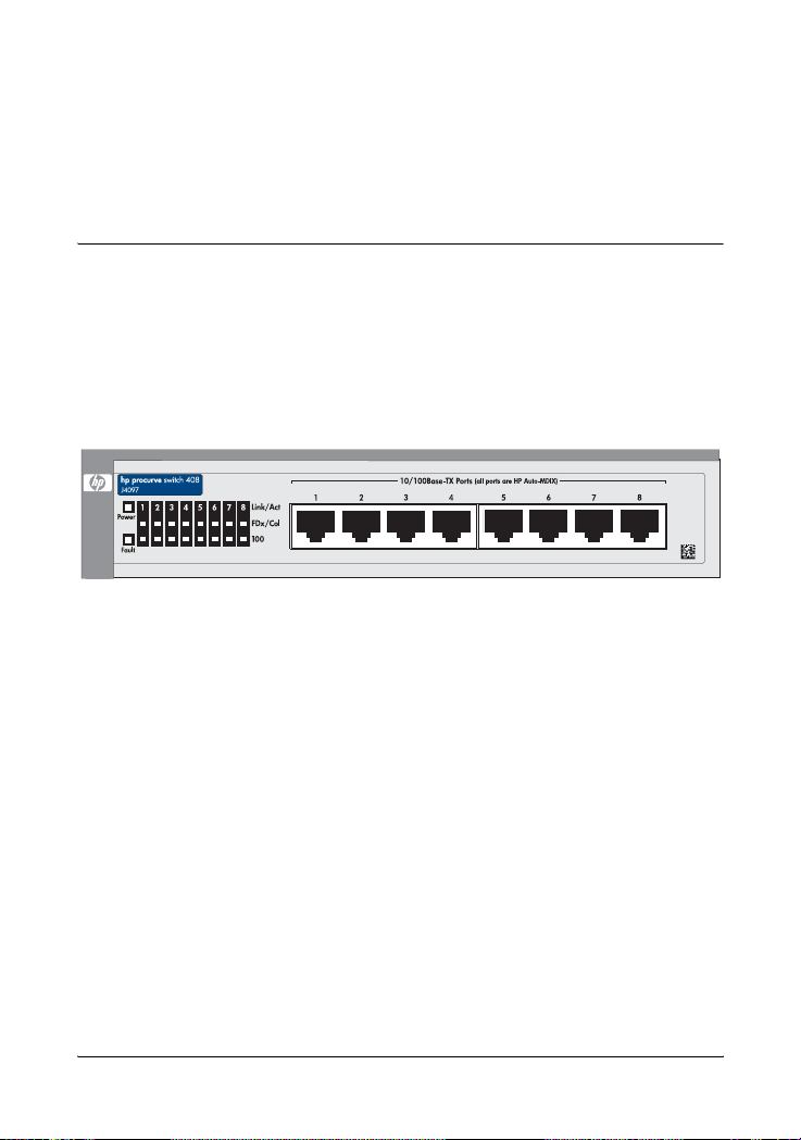
The Switch 408 has eight auto-sensing 10/100Base-TX RJ-45 ports.
With this switch you can build a switched network infrastructure by
connecting it to hubs, other switches, or routers; or you can connect
directly to computers, printers, and servers to provide dedicated
bandwidth to those devices.
This chapter describes your Switch 408 including:
■ Front and back of the switch
■ Features
■ Switch operation overview
1-1
Introducing the Switch 408
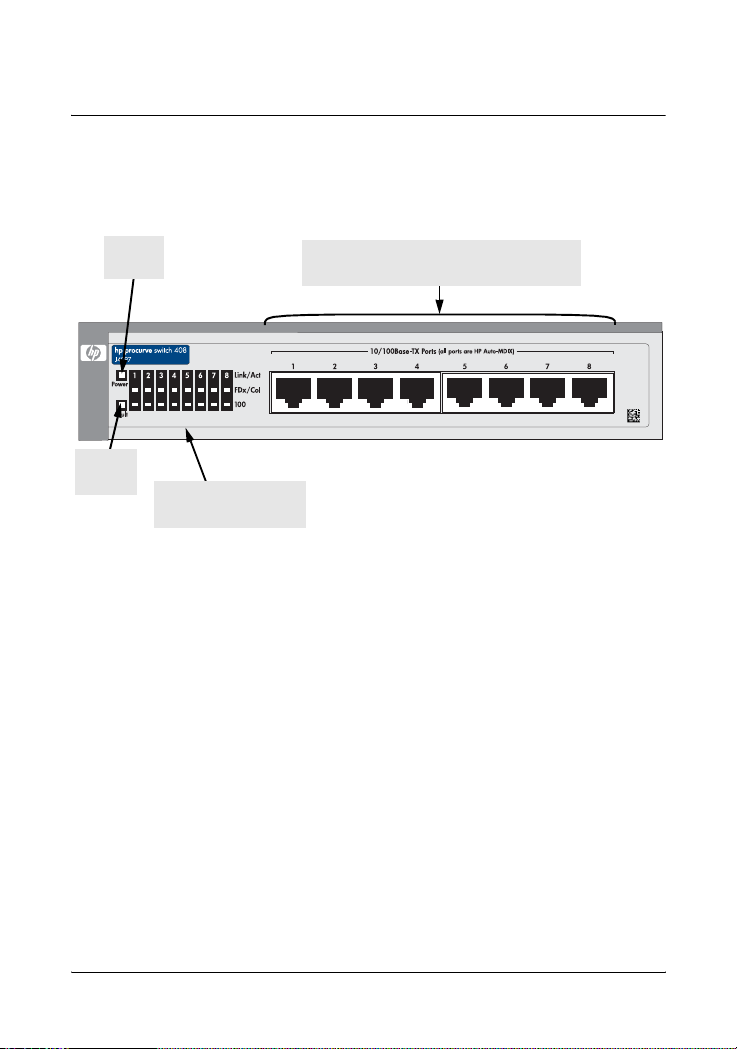
Front of the Switch
Front of the Switch
Fault
LED
Power
LED
C
Link/Act, FD x, and 100
LEDs for each port
10/100Base-TX RJ-45 ports
(all ports have the HP Auto-MDIX feature)
Network Ports
The switch has eight auto-sensing 10/100Base-TX ports with RJ-45
connectors. All of the ports have the HP Auto- MDIX feature, which
means that either a straight-through or cross-over cable can be used
for any connection to another device, and the switch automatically
adjusts the pin assignments to complete the connection.
1-2

LEDs
Table 1-1. Switch LEDs
Switch LEDs State Meaning
Introducing the Switch 408
Front of the Switch
Pwr
(green)
Fault
(orange)
Link/Act
(green –
overlaid with
the port
number)
FDx
(green)
100
(green)
On The switch is receiving power.
Off The switch is NOT receiving power.
Off The normal state; indicates that there are no fault
conditions on the switch.
On The switch has a hardware failure, or has failed
its self test. See chapter 3, “Troubleshooting” for
more information.
On Indicates the port is operating correctly and
receiving a link signal from the connected device.
Off One of these conditions exists:
• no active network cable is connected to the
port
• the port is not receiving a link signal
Flickering Indicates that there is network activity on the
port.
On The corresponding port is operating at full duplex
Off The corresponding port is operating at half duplex
On The corresponding port is operating at 100 Mbps.
Off The corresponding port is operating at 10 Mbps.
1-3
Introducing the Switch 408
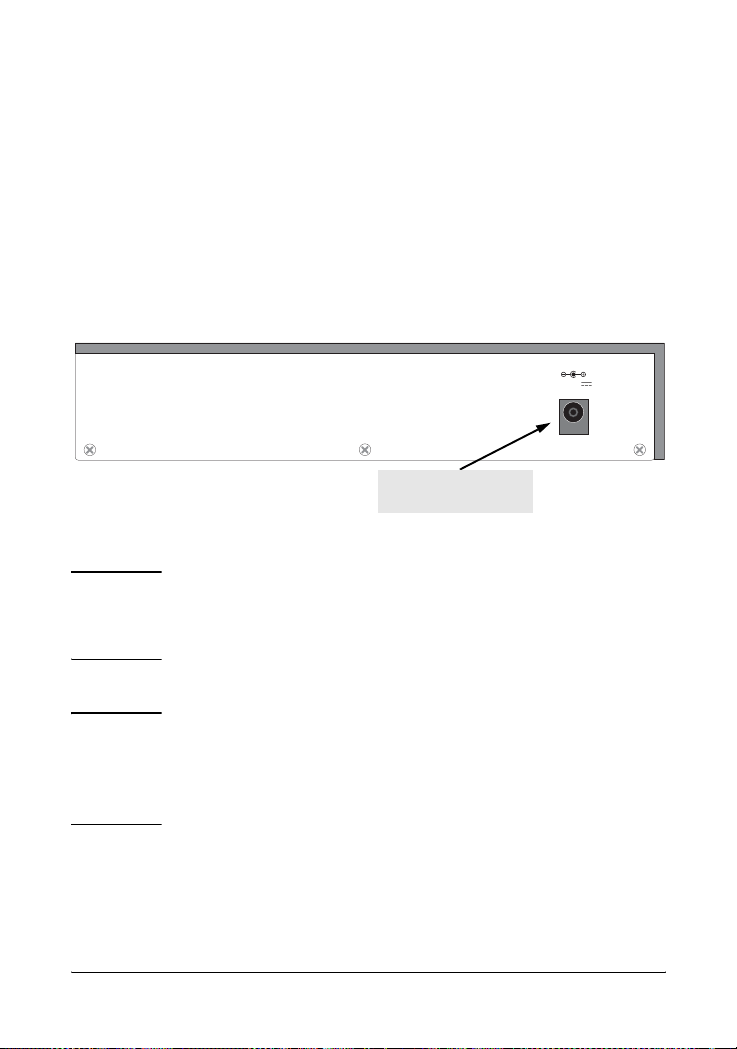
Back of the Switch
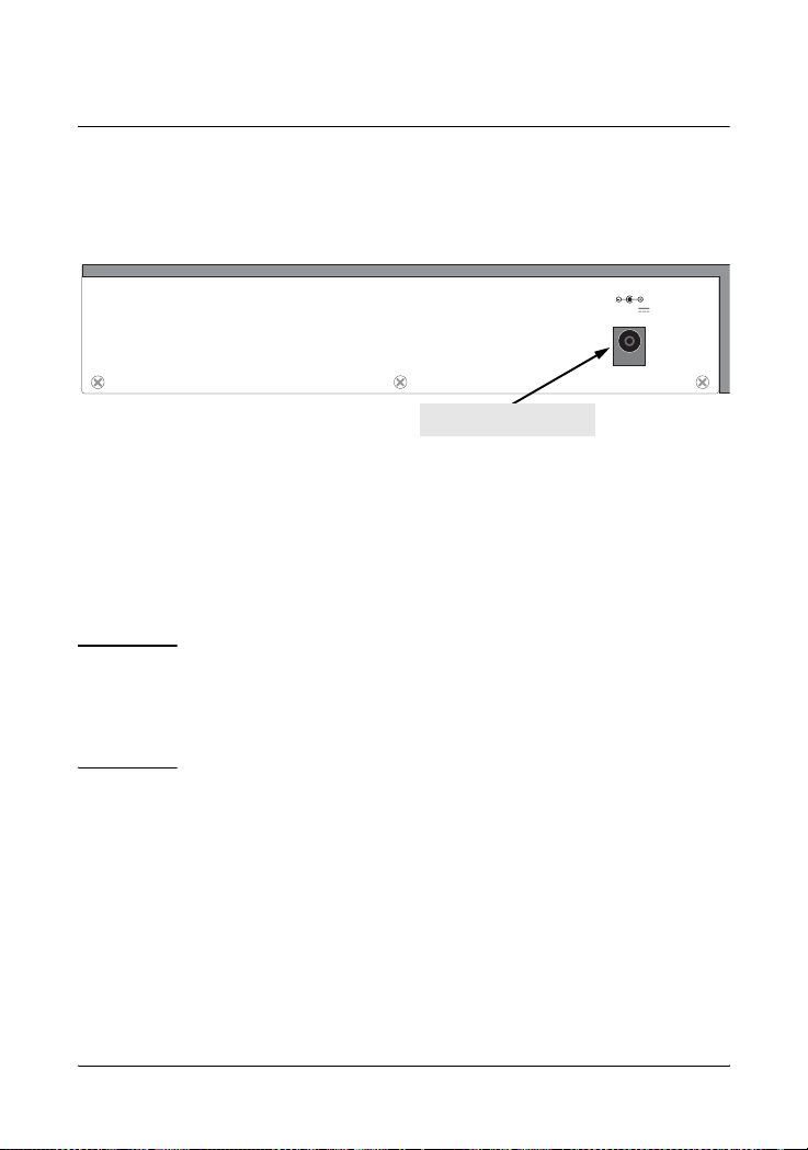
Back of the Switch
.
12 - 13V
1.0 - 0.8A
power connector
Power Connector
The Switch 408 does not have a power switch; it is powered on when
the AC power adapter is plugged in to an active power source and to
the switch.
Caution
1-4
Use only the AC power adapter supplied with the switch.
Use of other adapters, including adapters that came with
other HP network products, may result in damage to the
equipment.

Introducing the Switch 408
Features
Features
The features of the Switch 408 include:
■ eight auto-sensing 10/100Base-TX RJ-45 ports—all ports can
sense the connection speed, 10 Mbps or 100 Mbps, and automatically operate at that speed
■ HP Auto-MDIX on all ports—all ports allow you to use either a
straight-through or crossover cable to connect to any other
RJ-45 network device. There are no switches or buttons to deal
with, and no more worrying about what type of cable is needed
to connect to an end node, or to another switch or hub.
■ plug-and-play networking—all ports are enabled—just connect
the network cables to active network devices and your switched
network is operational
■ automatic learning of the hardware addresses in the switch’s
1000-entry address forwarding table
■ auto-negotiation of half/full duplex on all ports
■ auto-negotiation of flow control for ports operating at full duplex
Switch Operation Overview
Address Table Operation
Address Learning. As devices are connected to the switch ports,
either directly or through hubs or other switches that are connected
to the switch, the MAC addresses of those devices are learned auto-
1-5

Introducing the Switch 408
Switch Operation Overview
matically and stored in the Switch 408’s 1000-entry address table. The
switch also identifies the number of the port on which each address
is learned so it knows the relative network location of each device.
Forwarding, Filtering, Flooding. When the switch receives a
packet, it determines the destination address, and looks for the
address in the address table. Based on the port location of that
address, the switch then determines whether to forward, filter-out, or
flood the packet.
■ forward - if the destination address is on a different port than the
one on which the packet was received, the packet is forwarded
to the destination port and on to the destination device.
■ filter out - if the destination address is on the same port as the
one on which the packet was received, the packet is filtered out.
The switch thereby isolates local traffic so the rest of the network
connected to the switch does not use bandwidth dealing with
unnecessary traffic.
■ flood - whenever a new destination address is found in a packet
received on a port, the destination address will not yet be in the
switch’s address table and the Switch 408 cannot know whether
to forward or filter out the packet. In this case, it sends the packet
to all the other switch ports. This is referred to as “flooding”.
When the destination device receives the packet, it replies, and
the switch learns the new address from the reply packet. Then,
all future packets destined for that address are forwarded or
filtered out appropriately.
Network Moves and Changes. When devices are moved in the
network, and become connected to a different switch port, the Switch
408 automatically recognizes the change and updates the address
table with the new port locations of the devices. Communication with
the connected devices is thereby automatically maintained.
1-6

2
Installing the Switch 408
The ProCurve Switch 408 is easy to install. It comes with four rubber
feet that can be attached so the switch can be securely located on any
level surface (for example, a table or shelf). A mounting kit (5183-
7210) is also available that provides a variety of mounting options
including in a standard 19-inch EIA equipment rack or cabinet, on a
wall, or under a horizontal surface. Contact your HP Networking
products reseller to order the mounting kit.
This chapter shows you how to install your Switch 408.
Included Parts
The Switch 408 has the following components shipped with it:
■ ProCurve Switch 408 Installation Guide (5991-6250), this
manual
■ Customer Support/Warranty booklet
■ Four rubber feet
■ AC power adapter, one of the following:
Australia/New Zealand
China
Denmark/Switzerland
Europe/Russia
Japan
United Kingdom/Hong Kong/Singapore
United States/Canada/Taiwan
5188-5678
5188-5677
5188-5673
5188-5673
5188-5676
5188-5672
5188-5671
2-1

Installing the Switch 408
Installation Procedures
Japan Power Cord Warning
Installation Procedures
Summary
Follow these easy steps to install your switch. The rest of this chapter
provides details on these steps.
1. Prepare the installation site. Make sure of the following:
• the network cabling is the correct type and length. See page
2-5.
• the network topology is correct. See page 2-10.
• no devices connected to the switch have a fixed full-duplex
configuration (they must be able to auto-negotiate the duplex
mode or be fixed at half duplex). See page 2-4.
See page 2-3 for installation precautions.
2. Verify that the switch passes its self test. This is a simple
process of plugging the switch into a power source and observing
that the LEDs on the switch’s front panel show correct operation.
See page 2-7.
3. Mount the switch. The Switch 408 can be mounted on any
horizontal surface. The optional mounting kit (5183-7210)
provides other options including mounting two switch units sideby-side in a standard 19-inch telco rack or equipment cabinet.
4. Connect power to the switch. Once the switch is mounted, plug
in the AC power adapter. See page 2-9.
2-2

Installing the Switch 408
Installation Procedures
5. Connect the network devices. Using the appropriate network
cables, connect computers, servers, printers and other peripherals, and other network devices including other switches, hubs,
or routers to the switch ports. See page 2-9.
At this point, the switch is fully installed and your network should be
up and running. See the rest of this chapter if you need more detailed
information on any of these installation steps.
Installation Precautions
Follow these precautions when installing your Switch 408:
Cautions
■ Make sure you use the power adapter supplied with the
switch to connect it to an AC power source.
■ When installing the switch, since the unit does not have
an On/Off power switch, an AC power outlet must be
located near the switch and should be easily accessible
in case the switch needs to be powered off.
■ Make sure the switch does not overload the power
circuits, wiring, and over-current protection. To determine the possibility of overloading the supply circuits,
add together the amperage ratings of all devices installed
on the same circuit as the switch and compare the total
with the rating limit for the circuit. The maximum
amperage ratings are usually printed on the devices near
the AC power connectors or power adapter connectors.
■ Do not install the switch in an environment where the
operating ambient temperature might exceed 40°C
(104°F).
■ Make sure the air flow around the sides of the switch is
not restricted.
Continued on the next page.
2-3

Installing the Switch 408
Installation Procedures
■ If you rack mount the Switch 408 (using the mounting kit,
5183-7210), the rack or cabinet should be adequately
secured to prevent it from becoming unstable and/or
falling over. Devices installed in a rack or cabinet should
be mounted as low as possible, with the heaviest device
at the bottom and progressively lighter devices installed
above.
■ Connect no devices that have a fixed full-duplex
configuration. Because the switch 408 complies with
the IEEE 802.3u standard, if a device connected to the
switch has a fixed configuration of full duplex, the device
will not connect correctly to the switch. Make sure all
devices connected to the Switch 408 are configured to
auto negotiate, or are configured to connect at half
duplex. For more information, see the “Basic Troubleshooting Tips” in chapter 3, “Troubleshooting”.
2-4

Installing the Switch 408
Installation Procedures
1. Prepare the Installation Site
■ Cabling Infrastructure - Make sure the cabling infrastructure
meets the necessary network specifications. Because of the HP
Auto-MDIX feature, for connections to end nodes (computers,
servers, printers and other peripherals), or connections to hubs
or other switches, you can use straight-through cables. Crossover
cables can also be used for any of these connections. See the
following table for cable types and lengths, and see appendix B,
“Cables and Connectors” for more information:
Table 2-1. Summary of Cable Types to Use with the Switch
Port Type Cable Type Length Limits
10Base-T category 3, 4, or 5,
100-ohm unshielded
twisted-pair (UTP) or
shielded twisted-pair
(STP)
100Base-TX category 5, 100-ohm
UTP or STP
■ Installation Location - Before installing the switch, plan its
category 3, 4, or 5 - 100 meters
Note: Since the 10Base-T operation
is through 10/100Base-T X ports, if you
ever want to upgrade the ports to
100Base-T, it would be best to cable
the ports initially with category 5
cable.
100 meters
location and orientation relative to other devices and equipment.
At the front of the switch, leave at least 7.6 cm (3 inches) of space
for the twisted-pair cabling. At the back of the switch, leave at
least 2.6 cm (1 inch) of space for the adapter’s power cord.
2-5
Installing the Switch 408
Installation Procedures
2. Verify the Switch Passes Its Self Test
Before mounting the switch in its network location, you should first
check that it is working properly by plugging it into a power source
and verifying that it passes its self test.
1. Connect the adapter’s power cord to the power connector on the
back of the switch, and then plug the AC power adapter into a
nearby properly grounded electrical outlet.
12 - 13V
1.0 - 0.8A
Connect power cord to
the power connector
Note
The Switch 408 does not have a power switch. It is powered
on when the AC power adapter is connected to the switch
and to a power source.
Caution
Use only the AC power adapter supplied with the switch.
Use of other adapters, including those that came with other
HP network products, may result in damage to the equipment.
2. Check the LEDs on the switch. The LED behavior is described on
the next page.
2-6
 Loading...