

HP ProCurve 3400cl-48G, ProCurve 3400cl-24G Installation And Getting Started Manual
ProCurve Series
3400cl Switches
Installation and
Getting Started Guide
www.procurve.com


ProCurve Series 3400cl Switch
Installation and Getting Started Guide

© Copyright 2004, 2006 Hewlett-Packard Development Company,
L.P. The information contained herein is subject to change
without notice.
This document contains proprietary information, which is
protected by copyright. No part of this document may be
photocopied, reproduced, or translated into another
language without prior written consent of Hewlett-Packard.
Publication Number
5991-4702
March 2006
Applicable Products
ProCurve Switch 3400cl-24G (J4905A)
ProCurve Switch 3400cl-48G (J4906A)
ProCurve 600 Redundant and External
Power Supply (J8168A)
ProCurve 10-GbE X2-SC SR Optic (J8436A)
ProCurve 10-GbE X2-SC LR Optic (J8437A)
ProCurve 10-GbE X2-SC ER Optic (J8438A)
ProCurve 10-GbE CX4 Media Converter (J8439A)
ProCurve 10-GbE X2-CX4 Transceiver (J8440A)
ProCurve 10-Gig Copper Module (J8434A)
ProCurve 10-Gig Media Flex Module (J8435A)
Disclaimer
HEWLETT-PACKARD COMPANY MAKES NO WARRANTY
OF ANY KIND WITH REGARD TO THIS MATERIAL,
INCLUDING, BUT NOT LIMITED TO, THE IMPLIED
WARRANTIES OF MERCHANTABILITY AND FITNESS
FOR A PARTICULAR PURPOSE. Hewlett-Packard shall not
be liable for errors contained herein or for incidental or
consequential damages in connection with the furnishing,
performance, or use of this material.
The only warranties for HP products and services are set
forth in the express warranty statements accompanying
such products and services. Nothing herein should be
construed as constituting an additional warranty. HP shall
not be liable for technical or editorial errors or omissions
contained herein.
Hewlett-Packard assumes no responsibility for the use or
reliability of its software on equipment that is not furnished
by Hewlett-Packard.
Warranty
See the Customer Support/Warranty booklet included with
the product.
A copy of the specific warranty terms applicable to your
Hewlett-Packard products and replacement parts can be
obtained from your HP Sales and Service Office or
authorized dealer.
Trademark Credits
Windows NT®, Windows®, and MS Windows® are US
registered trademarks of Microsoft Corporation.
Adobe® and Acrobat® are trademarks of Adobe Systems
Incorporated. Java™ is a US trademark of Sun
Microsystems, Inc.
Hewlett-Packard Company
8000 Foothills Boulevard, m/s 5552
Roseville, California 95747-5552
http://www.procurve.com
Safety
Before installing and operating these products, please read
the “Installation Precautions” in chapter 2, “Installing the
Switch”, and the safety statements in appendix C, “Safety
and EMC Regulatory Statements”.

Contents
1 Introducing the Switch
Front of the Switch . . . . . . . . . . . . . . . . . . . . . . . . . . . . . . . . . . . . . . . . . . . . . . 1-3
Network Ports . . . . . . . . . . . . . . . . . . . . . . . . . . . . . . . . . . . . . . . . . . . . . . 1-4
LEDs . . . . . . . . . . . . . . . . . . . . . . . . . . . . . . . . . . . . . . . . . . . . . . . . . . . . . . 1-5
LED Mode Select Button and Indicator LEDs . . . . . . . . . . . . . . . . . . . . 1-7
Reset Button . . . . . . . . . . . . . . . . . . . . . . . . . . . . . . . . . . . . . . . . . . . . . . . 1-8
Clear Button . . . . . . . . . . . . . . . . . . . . . . . . . . . . . . . . . . . . . . . . . . . . . . . 1-8
Expansion Module LEDs . . . . . . . . . . . . . . . . . . . . . . . . . . . . . . . . . . . . . 1-9
Back of the Switch . . . . . . . . . . . . . . . . . . . . . . . . . . . . . . . . . . . . . . . . . . . . . 1-10
Console Port . . . . . . . . . . . . . . . . . . . . . . . . . . . . . . . . . . . . . . . . . . . . . . 1-10
Power Connector . . . . . . . . . . . . . . . . . . . . . . . . . . . . . . . . . . . . . . . . . . 1-10
Switch Features . . . . . . . . . . . . . . . . . . . . . . . . . . . . . . . . . . . . . . . . . . . . . . . 1-11
2 Installing the Switch
Included Parts . . . . . . . . . . . . . . . . . . . . . . . . . . . . . . . . . . . . . . . . . . . . . . . . . . 2-1
Installation Procedures . . . . . . . . . . . . . . . . . . . . . . . . . . . . . . . . . . . . . . . . . . 2-3
Summary . . . . . . . . . . . . . . . . . . . . . . . . . . . . . . . . . . . . . . . . . . . . . . . . . . . 2-3
Installation Precautions: . . . . . . . . . . . . . . . . . . . . . . . . . . . . . . . . . . . . . . 2-4
1. Prepare the Installation Site . . . . . . . . . . . . . . . . . . . . . . . . . . . . . . . . 2-5
2. (Optional) Install or Remove a cl Module . . . . . . . . . . . . . . . . . . . . . 2-7
3. (Optional) Install or Remove a Transceiver . . . . . . . . . . . . . . . . . . . 2-8
4. (Optional) Install or Remove mini-GBICs . . . . . . . . . . . . . . . . . . . . . 2-9
5. Verify the Switch Passes Self Test . . . . . . . . . . . . . . . . . . . . . . . . . . 2-11
LED Behavior: . . . . . . . . . . . . . . . . . . . . . . . . . . . . . . . . . . . . . . . . . 2-12
6. Mount the Switch . . . . . . . . . . . . . . . . . . . . . . . . . . . . . . . . . . . . . . . . 2-13
Rack or Cabinet Mounting . . . . . . . . . . . . . . . . . . . . . . . . . . . . . . . 2-13
Rack Mounting the Switch 3400cl-48G . . . . . . . . . . . . . . . . . . . . . 2-14
Rack Mounting the Switch 3400cl-24G . . . . . . . . . . . . . . . . . . . . . 2-16
Horizontal Surface Mounting . . . . . . . . . . . . . . . . . . . . . . . . . . . . . 2-19
iii

7. Connect the Switch to a Power Source . . . . . . . . . . . . . . . . . . . . . . 2-19
8. Connect the Network Cables . . . . . . . . . . . . . . . . . . . . . . . . . . . . . . . 2-20
Using the RJ-45 Connectors . . . . . . . . . . . . . . . . . . . . . . . . . . . . . . 2-20
Connecting Cables to mini-GBICs . . . . . . . . . . . . . . . . . . . . . . . . . 2-20
9. (Optional) Connect a Redundant Power Supply to the
Switch . . . . . . . . . . . . . . . . . . . . . . . . . . . . . . . . . . . . . . . . . . . . . . . . . 2-21
10. (Optional) Connect a Console to the Switch . . . . . . . . . . . . . . . . . 2-24
Terminal Configuration . . . . . . . . . . . . . . . . . . . . . . . . . . . . . . . . . . 2-24
Direct Console Access . . . . . . . . . . . . . . . . . . . . . . . . . . . . . . . . . . . 2-25
Sample Network Topologies . . . . . . . . . . . . . . . . . . . . . . . . . . . . . . . . . . . . . 2-26
As a Desktop Switch . . . . . . . . . . . . . . . . . . . . . . . . . . . . . . . . . . . . . . . . 2-26
As a Segment Switch . . . . . . . . . . . . . . . . . . . . . . . . . . . . . . . . . . . . . . . . 2-27
Connecting to a Backbone Switch . . . . . . . . . . . . . . . . . . . . . . . . . . . . 2-29
Stacking the Switch . . . . . . . . . . . . . . . . . . . . . . . . . . . . . . . . . . . . . . . . . 2-30
The Switch in a Redundant Topology . . . . . . . . . . . . . . . . . . . . . . . . . . 2-31
3 Getting Started With Switch Configuration
Recommended Minimal Configuration . . . . . . . . . . . . . . . . . . . . . . . . . . 3-1
Using the Console Setup Screen . . . . . . . . . . . . . . . . . . . . . . . . . . . . . . . 3-2
Where to Go From Here . . . . . . . . . . . . . . . . . . . . . . . . . . . . . . . . . . . . . . 3-4
To Recover from a Lost Manager Password: . . . . . . . . . . . . . . 3-4
iv
Using the IP Address for Remote Switch Management . . . . . . . . . . . . . . . . 3-5
Starting a Telnet Session . . . . . . . . . . . . . . . . . . . . . . . . . . . . . . . . . . . . . 3-5
Starting a Web Browser Session . . . . . . . . . . . . . . . . . . . . . . . . . . . . . . . 3-5
4 Troubleshooting
Basic Troubleshooting Tips . . . . . . . . . . . . . . . . . . . . . . . . . . . . . . . . . . . . . . 4-1
Diagnosing with the LEDs . . . . . . . . . . . . . . . . . . . . . . . . . . . . . . . . . . . . . . . . 4-4
Proactive Networking . . . . . . . . . . . . . . . . . . . . . . . . . . . . . . . . . . . . . . . . . . . 4-8
Hardware Diagnostic Tests . . . . . . . . . . . . . . . . . . . . . . . . . . . . . . . . . . . . . . . 4-9
Testing the Switch by Resetting It . . . . . . . . . . . . . . . . . . . . . . . . . . . . . 4-9
Checking the Switch LEDs . . . . . . . . . . . . . . . . . . . . . . . . . . . . . . . . 4-9
Checking Console Messages . . . . . . . . . . . . . . . . . . . . . . . . . . . . . . . 4-9
Testing Twisted-Pair Cabling . . . . . . . . . . . . . . . . . . . . . . . . . . . . . . . . . 4-10
Testing Switch-to-Device Network Communications . . . . . . . . . . . . 4-10
Testing End-to-End Network Communications . . . . . . . . . . . . . . . . . 4-10

Restoring the Factory Default Configuration . . . . . . . . . . . . . . . . . . . . . . . 4-11
Downloading New Switch Software . . . . . . . . . . . . . . . . . . . . . . . . . . . . . . 4-12
HP Customer Support Services . . . . . . . . . . . . . . . . . . . . . . . . . . . . . . . . . . 4-13
Before Calling Support . . . . . . . . . . . . . . . . . . . . . . . . . . . . . . . . . . . . . . 4-13
A Specifications
Physical . . . . . . . . . . . . . . . . . . . . . . . . . . . . . . . . . . . . . . . . . . . . . . . . . . A-1
Electrical . . . . . . . . . . . . . . . . . . . . . . . . . . . . . . . . . . . . . . . . . . . . . . . . . A-1
Environmental . . . . . . . . . . . . . . . . . . . . . . . . . . . . . . . . . . . . . . . . . . . . A-1
Acoustic . . . . . . . . . . . . . . . . . . . . . . . . . . . . . . . . . . . . . . . . . . . . . . . . . . A-2
Connectors . . . . . . . . . . . . . . . . . . . . . . . . . . . . . . . . . . . . . . . . . . . . . . . . A-2
Safety . . . . . . . . . . . . . . . . . . . . . . . . . . . . . . . . . . . . . . . . . . . . . . . . . . . . A-2
Lasers . . . . . . . . . . . . . . . . . . . . . . . . . . . . . . . . . . . . . . . . . . . . . . . . . . . . A-2
B Switch Ports and Network Cables
Switch Ports . . . . . . . . . . . . . . . . . . . . . . . . . . . . . . . . . . . . . . . . . . . . . . . B-1
Twisted-Pair Cables . . . . . . . . . . . . . . . . . . . . . . . . . . . . . . . . . . . . . . . . B-1
Note on 1000Base-T Cable Requirements . . . . . . . . . . . . . . . . B-1
Mode Conditioning Patch Cord for Gigabit-LX . . . . . . . . . . . . . . . . . . . . . B-3
Installing the Patch Cord . . . . . . . . . . . . . . . . . . . . . . . . . . . . . . . . . . . . B-4
Recommended Patch Cords . . . . . . . . . . . . . . . . . . . . . . . . . . . . . . . . . . B-4
Twisted-Pair Cable/Connector Pin-Outs . . . . . . . . . . . . . . . . . . . . . . . . . . . B-5
Auto-MDIX Feature: . . . . . . . . . . . . . . . . . . . . . . . . . . . . . . . . . . B-5
Using Fixed Configurations . . . . . . . . . . . . . . . . . . . . . . . . . . . . B-5
Other Wiring Rules: . . . . . . . . . . . . . . . . . . . . . . . . . . . . . . . . . . . B-5
Straight-Through Twisted-Pair Cable for
10 Mbps or 100 Mbps Network Connections . . . . . . . . . . . . . . . . . . . . B-7
Cable Diagram . . . . . . . . . . . . . . . . . . . . . . . . . . . . . . . . . . . . . . . . . B-7
Pin Assignments . . . . . . . . . . . . . . . . . . . . . . . . . . . . . . . . . . . . . . . B-7
Crossover Twisted-Pair Cable for
10 Mbps or 100 Mbps Network Connection . . . . . . . . . . . . . . . . . . . . . B-8
Cable Diagram . . . . . . . . . . . . . . . . . . . . . . . . . . . . . . . . . . . . . . . . . B-8
Pin Assignments . . . . . . . . . . . . . . . . . . . . . . . . . . . . . . . . . . . . . . . B-8
Straight-Through Twisted-Pair Cable for
1000 Mbps Network Connections . . . . . . . . . . . . . . . . . . . . . . . . . . . . . B-9
Cable Diagram . . . . . . . . . . . . . . . . . . . . . . . . . . . . . . . . . . . . . . . . . B-9
Pin Assignments . . . . . . . . . . . . . . . . . . . . . . . . . . . . . . . . . . . . . . . B-9
v

C Safety and EMC Regulatory Statements
Safety Information . . . . . . . . . . . . . . . . . . . . . . . . . . . . . . . . . . . . . . . . . . . . . C-1
Informations concernant la sécurité . . . . . . . . . . . . . . . . . . . . . . . . . . . . . . C-2
Hinweise zur Sicherheit . . . . . . . . . . . . . . . . . . . . . . . . . . . . . . . . . . . . . . . . . C-3
Considerazioni sulla sicurezza . . . . . . . . . . . . . . . . . . . . . . . . . . . . . . . . . . . C-4
Consideraciones sobre seguridad . . . . . . . . . . . . . . . . . . . . . . . . . . . . . . . . C-5
Safety Information (Japan) . . . . . . . . . . . . . . . . . . . . . . . . . . . . . . . . . . . . . . C-6
Safety Information (China) . . . . . . . . . . . . . . . . . . . . . . . . . . . . . . . . . . . . . . C-7
EMC Regulatory Statements . . . . . . . . . . . . . . . . . . . . . . . . . . . . . . . . . . . . . C-8
U.S.A. . . . . . . . . . . . . . . . . . . . . . . . . . . . . . . . . . . . . . . . . . . . . . . . . . . . . C-8
Canada . . . . . . . . . . . . . . . . . . . . . . . . . . . . . . . . . . . . . . . . . . . . . . . . . . . C-8
Australia/New Zealand . . . . . . . . . . . . . . . . . . . . . . . . . . . . . . . . . . . . . . C-8
Japan . . . . . . . . . . . . . . . . . . . . . . . . . . . . . . . . . . . . . . . . . . . . . . . . . . . . . C-8
Korea . . . . . . . . . . . . . . . . . . . . . . . . . . . . . . . . . . . . . . . . . . . . . . . . . . . . . C-9
Taiwan . . . . . . . . . . . . . . . . . . . . . . . . . . . . . . . . . . . . . . . . . . . . . . . . . . . C-9
European Community . . . . . . . . . . . . . . . . . . . . . . . . . . . . . . . . . . . . . . C-10
D Recycle Statements
Waste Electrical and Electronic Equipment (WEEE) Statements . . . . . . D-1
Index
vi
Introducing the Switch
The ProCurve Switches 3400cl are multiport switches that can be used to build
high-performance switched workgroup networks. These switches are storeand-forward devices offering low latency for high-speed networking.
1
Introducing the Switch
ProCurve Switch 3400cl-24G (J4905A)
ProCurve Switch 3400cl-48G (J4906A)
Throughout this manual, this switch will be abbreviated as the Switch 3400cl24G or Switch 3400cl-48G and collectively as the Series 3400cl Switch devices.
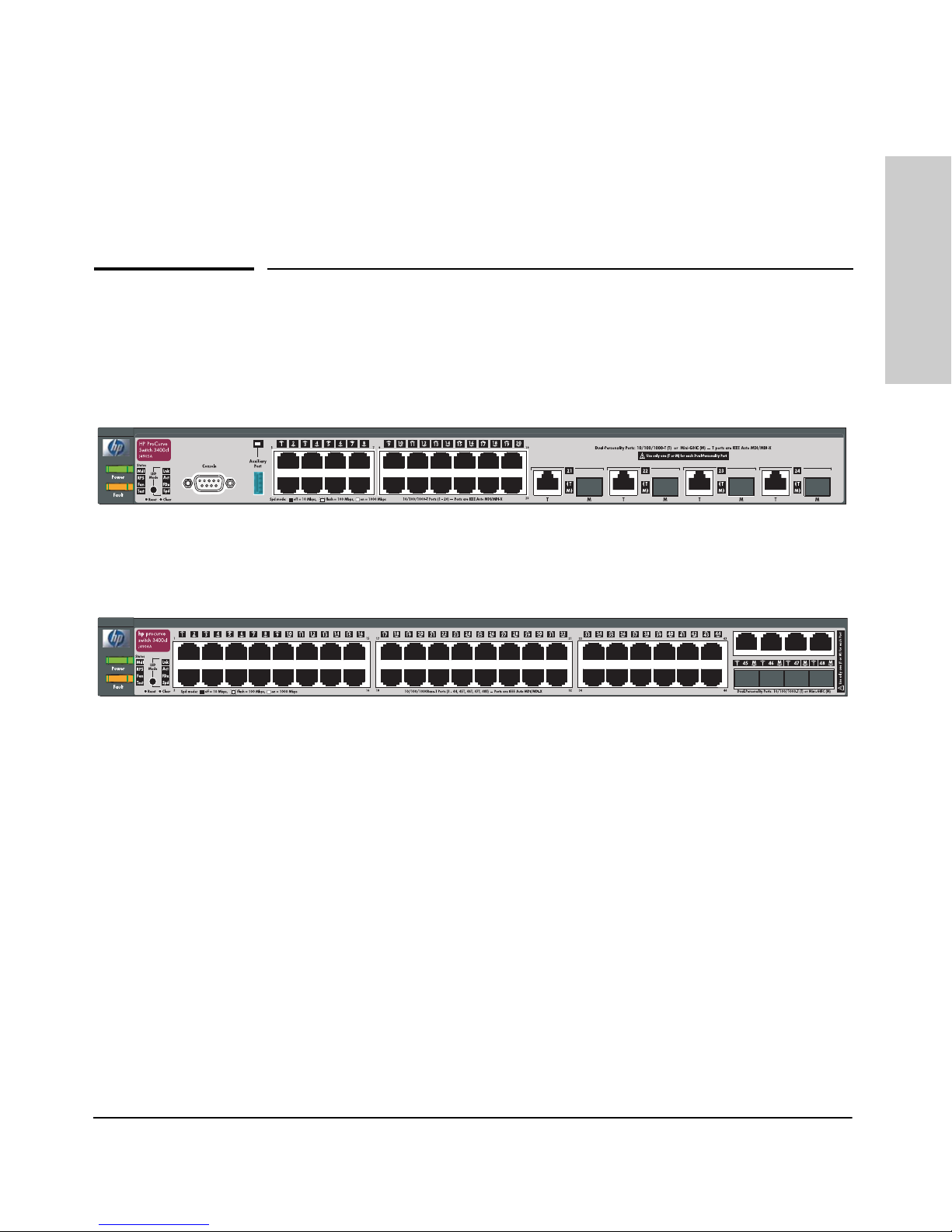
The Switch 3400cl-24G and Switch 3400cl-48G have respectively, 24 or 48,
auto-sensing 10/100/1000Base-T RJ-45 ports, four dual-personality ports—
either auto-sensing 10/100/1000Base-T RJ-45 or mini-GBIC, and one slot is
provided in the back of the device to support a two port 10 Gigabit per second
Ethernet (10-GbE) module to provide box connectivity to other switch boxes,
to a 10 Gigabit per second concentrator or to any Ethernet compatible uplink.
The Series 3400cl Switch devices can be connected to a ProCurve
RPS/EPS (J8168A) and receive full redundant power from that unit. If the
internal power supply in the switch fails, the RPS/EPS unit will immediately
provide all the power necessary to keep the switch running.
1-1

Introducing the Switch
These switches are designed to be used primarily as a high-density wiring
closet or desktop switch. These switches can directly connect computers,
printers, and servers to provide dedicated bandwidth to those devices, and can
build a switched network infrastructure by connecting the switch to hubs,
other switches, or routers. In addition, the Series 3400cl Switch devices offer
full network management capabilities.
This chapter describes the Series 3400cl Switch devices, including:
Introducing the Switch
■ Front and back of the switches
■ Switch features
1-2
Introducing the Switch
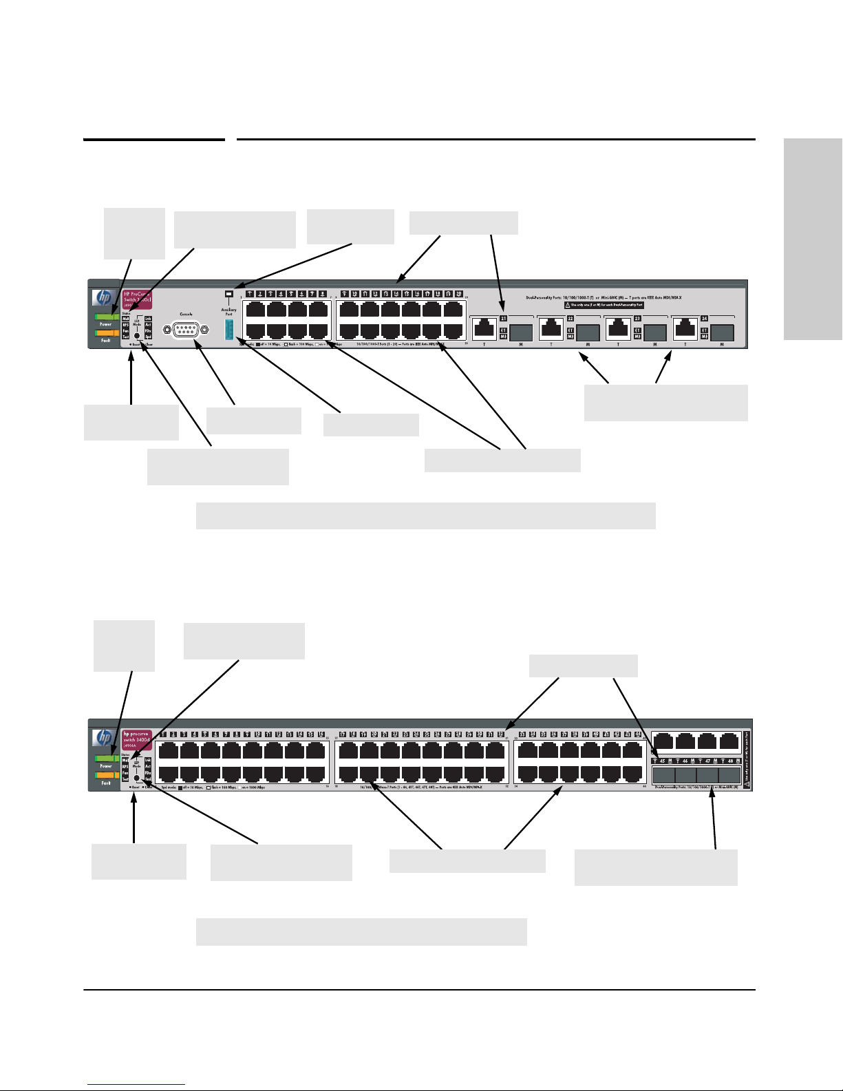
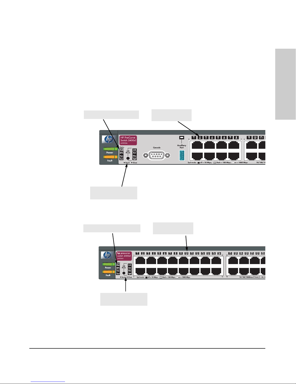
Front of the Switch
Power
and Fault
LEDs
Reset and Clear
buttons
button and indicator LEDs
Front of the Switch
Test, Fan, RPS, and
Module Status LEDs
Console port*
Port LED Mode select
*On the 3400cl-48G switch, the console and Auxiliary ports are located on the back of the unit.
Auxiliary port
LED
Auxiliary port*
Switch port LEDs
10/100/1000-T RJ-45 ports
Introducing the Switch
ProCurve Switch 3400cl-24G
Dual-personality ports
(1000Base-T or mini-GBIC)
Power
and Fault
LEDs
Reset and Clear
buttons
Test, Fan, RPS, and
Module Status LEDs
Port LED Mode select
button and indicator LEDs
*
10/100/1000Base-T ports have the IEEE Auto MDI/MDI-X feature.
10/100/1000-T RJ-45 ports* Dual-personality ports
ProCurve Switch 3400cl-48G
Switch port LEDs
(1000Base-T* or mini-GBIC)
1-3

Introducing the Switch
Front of the Switch
Network Ports
■ 24 or 48 auto-sensing 10/100/1000Base-T ports.
All these ports have the “HP Auto MDIX” feature, which means you can
use either straight-through or crossover twisted-pair cables to connect
any network devices to the switch.
■ Four dual-personality ports. Use either the 10/100/1000Base-T RJ-45
connector, or install a supported ProCurve mini-GBIC for fiber-optic
Introducing the Switch
connections.
The RJ-45 connectors support the IEEE Auto MDI/MDI-X feature, which
means you can use either straight-through or crossover twisted-pair
cables to connect any network device to the switch.
Dual-Personality Port Operation. By default, the RJ-45 connectors are
enabled. If a mini-GBIC is installed in a slot, it is enabled and the associated
RJ-45 connector is disabled and cannot be used. If the mini-GBIC is
removed, the associated RJ-45 port is automatically re-enabled.
■ One, 10 gigabit expansion slot. These switches provide a single slot in the
back of the device that can accept a 2 x 10 gigabit transceiver module. The
module provides two 10 gigabit ports. The module may provide either
copper or fiber optic media that conforms to the gigabit Ethernet standard
as well as dual 10 gigabit copper or uplink ports.
1-4
LEDs
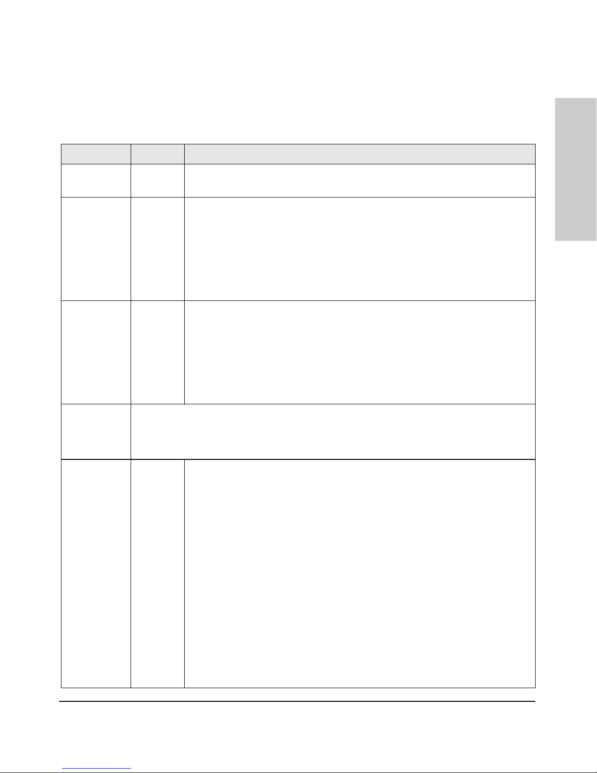
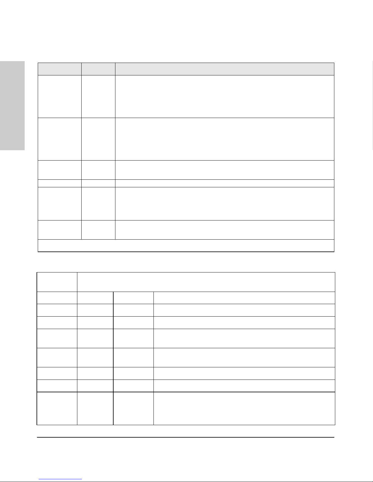
Table 1-1. Switch LEDs
Switch LEDs State Meaning
Introducing the Switch
Front of the Switch
Introducing the Switch
Power
(green)
Fault
(orange)
Te st
(green)
Port LEDs
(green – over-
laid with the
port number)
On
Off
Off The normal state; indicates there are no fault conditions on the switch.
Blinking* A fault has occurred on the switch, one of the switch ports, module in the rear of the
On On briefly after the switch is powered on or reset, at the beginning of switch self test.
Off The normal operational state; the switch is not undergoing self test.
On The switch self test and initialization are in progress after the switch has been power
Blinking* A component of the switch has failed its self test. The status LED for that component,
Displays port link information, network activity information, whether the port is configured for fullduplex operation, or the speed of the connection depending on the Port LED View selected. See “Port
LED View Select Button and Indicator LEDs” on the next page for more information. If a fault has
occurred on the port, the port LED will blink with the Fault LED.
The switch is receiving power.
The switch is NOT receiving power.
switch, or the fan. The Status LED for the component with the fault will blink
simultaneously.
If this LED is on for a prolonged time, the switch has encountered a fatal hardware
failure, or has failed its self test. See chapter 4, “Troubleshooting” for more information.
cycled or reset. The switch is not operational until this LED goes off. The Self Test LED
also comes on briefly when you “hot swap” a mini-GBIC into the switch; the mini-GBIC
is self tested when it is hot swapped.
for example an RJ-45 port, and the switch Fault LED will blink simultaneously.
LED Mode
View (4 green
LEDs)
Link Indicates the port LEDs are displaying link information:
• if the port LED is on, the port is enabled and receiving a link indication from the
connected device.
• if the port LED is off, the port has no active network cable connected, or is not
receiving link beat or sufficient light. Otherwise, the port may have been disabled
through the switch console, the web browser interface, or ProCurve Manager.
• if the port LED is blinking* simultaneously with the Fault LED, the corresponding port
has failed its self test.
Act Indicates the port LEDs are displaying network activity information.
FDx Indicates port LEDs are lit for ports in Full Duplex Mode. Off indicates ½ duplex.
Spd Indicates the port LEDs are displaying the connection speed at which each port is
operating:
• if the port LED is off, the port is operating at 10 Mbps.
• if the port LED is flashing**, the port is operating at 100 Mbps.
• if the port LED is on continuously, the port is operating at 1000 Mbps.
** The flashing behavior is an on/off cycle once every 0.5 seconds, approximately.
1-5
Introducing the Switch
Front of the Switch
Switch LEDs State Meaning
Mdl (Module
Status, green)
RPS Status
Introducing the Switch
(green)
Fan Status
(green)
T/M
(green – ports
21 - 24 or 45-
48)
Auxiliary
(green)
* The blinking behavior is an on/off cycle once every 1.6 seconds, approximately.
On
Blinking
Off
On
Blinking
Off
On
Blinking*
On For the dual-personality ports, indicates the enabled port:
On
Off
Expansion module is plugged into expansion slot and operating correctly
Expansion module is plugged into expansion slot but has experienced a fault
Expansion module is not plugged into expansion slot
Normal operation. RPS is connected and operating correctly. RPS could be powering
the unit - see table below.
RPS is connected but has experienced a fault.
RPS is not connected or is not powered.
Normal operation, all fans are ok.
One of the unit’s fans has failed. The switch Fault LED will be blinking simultaneously.
• if the “T” is on, the 10/100/1000Base-T RJ-45 port is enabled.
• if the “M” is on, the mini-GBIC port is enabled.
Port is in use
Port is not in use
Table 1-2. RPS LED Behavior
RPS modes This table describes the behavior of the RPS LED associated with the 600 RPS/EPS operation. (Power,
RPS/EPS, Fault)
Power LED RPS LED Fault LED Description
On Off Off Normal operation. The 600 RPS/EPS is not connected or not powered.
On On Off Normal operation. The 600 RPS/EPS is available.
On On/Off Blinking Unit has experienced a fault and another LED will be blinking to
determine fault.
On On Blinking The 600 RPS/EPS is running the switch in failover mode. No AC power
to the unit, or the internal power supply has failed.
Off Off Off Unit is un-powered by AC input line and the external 600 RPS/EPS
On Blinking Blinking The 600 RPS/EPS unit has experienced a fault.
On Blinking Off The 600 RPS/EPS unit is unavailable to power the Switch in event of an
internal power supply failure. The 600 RPS/EPS is designed to provide
power to one of its connected switch devices at a time. The Power
Status LED on the 600 RPS/EPS unit will also be blinking for this device.
1-6
Introducing the Switch
Front of the Switch
LED Mode Select Button and Indicator LEDs
To optimize the amount of information displayed for each of the switch ports
without overwhelming you with LEDs, the Series 3400cl Switch devices use a
single LED for each port. The operation of this LED is controlled by the LED
Mode select button, and the current setting is indicated by the LED Mode
indicator LEDs near the button. Press the button to step from one view mode
to the next.
Introducing the Switch
Expansion Module LED
LED Mode select button
and indicator LEDs
Expansion Module LEDs
Port LED
(one for each port)
Port LED
(one for each port)
ProCurve Switch 3400cl-24G
ProCurve Switch 3400cl-48G
LED Mode select button
and indicator LEDs
1-7

Introducing the Switch
Front of the Switch
■ If the Link (Lnk) indicator LED is lit, each port LED displays link infor-
mation for the associated port.
If the port LED is in Link mode and it is blinking, the port has failed its
self test. The Fault and Self Test LEDs will be blinking simultaneously.
■ If the Activity (Act) indicator LED is lit, each port LED displays activity
information for the associated port—it flickers as network traffic is
received and transmitted through the port.
■ If the Full Duplex (FDx) indicator LED is lit, the port LEDs light for those
Introducing the Switch
ports that are operating in full duplex.
■ If the Speed (Spd) indicator LED is lit, the port LEDs behave as follows
to indicate the connection speed for the port:
• Off = 10 Mbps
• Flashing = 100 Mbps (the flashing behavior is a repeated on/off cycle
once every 0.5 sec.)
• On = 1000 Mbps
Reset Button
This button is used to reset the switch while it is powered on. This action clears
any temporary error conditions that may have occurred and executes the
switch self test.
Clear Button
This button is used for these purposes:
■ Deleting Passwords - When pressed by itself for at least one second, the
button deletes any switch console access passwords that you may have
configured. Use this feature if you have misplaced the password and need
console access.
This button is provided for your convenience, but its presence means that
if you are concerned with the security of the switch configuration and
operation, you should make sure the switch is installed in a secure
location, such as a locked wiring closet.
■ Restoring Factory Default Configuration - When pressed with the
Reset button in a specific pattern, any configuration changes you may
have made through the switch console, the web browser interface, and
SNMP management are removed, and the factory default configuration is
restored to the switch. For the specific method to restore the factory
default configuration, see “Restoring the Factory Default Configuration”
on page 11, in chapter 4, “Troubleshooting” of this manual.
1-8
Expansion Module LEDs
“Expansion Module” LEDs refer to the LEDs specific to the expansion module.
These LEDs are located on the physical expansion module bulkhead. These
LEDs are only viewable in the rear of the Switch 3400cl-48G product on the
Expansion Slot Module itself.
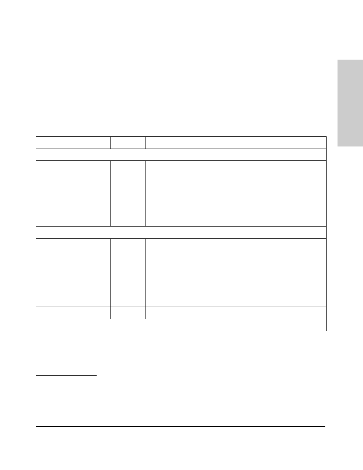
Table 1-3. Expansion Module LEDs
Name Color Mode Description
Expansion Module LEDs per module
Introducing the Switch
Front of the Switch
Introducing the Switch
Module
(Mdl) Power
(ports A & B)
Module
(Mdl) Fault
(ports A & B)
Expansion Module LEDs per port
Link Green On
Act Green On Indicates the port LEDs are displaying network activity information.
* The blinking behavior is an on/off cycle once every 1.6 seconds, approximately.
Green
Orange
On
Off
On
Off
Blinking
Expansion module is plugged into expansion slot and operating correctly
Expansion module's power has been turned OFF, and the card can be
removed from the box if necessary.
Expansion module is plugged into expansion slot but has experienced a
fault
Indicates that the port LEDs are displaying link information:
• if the port LED is on, the port is enabled and receiving a link indication
from the connected device.
• if the port LED is off, the port has no active network cable connected,
or is not receiving link beat or sufficient light. Otherwise, the port may
have been disabled through the switch console, the web browser
interface, or ProCurve Manager.
• if the port LED is blinking* simultaneously with the Fault LED, the
corresponding port has failed its self test.
Expansion module LEDs for port A and B operate in modes for Link and
Activity. FDx and Spd modes have no meaning for the 10-GbE ports on the
expansion module.
Caution It is recommended the power to the switch be removed before inserting or
extracting the Expansion Module.
1-9
Introducing the Switch
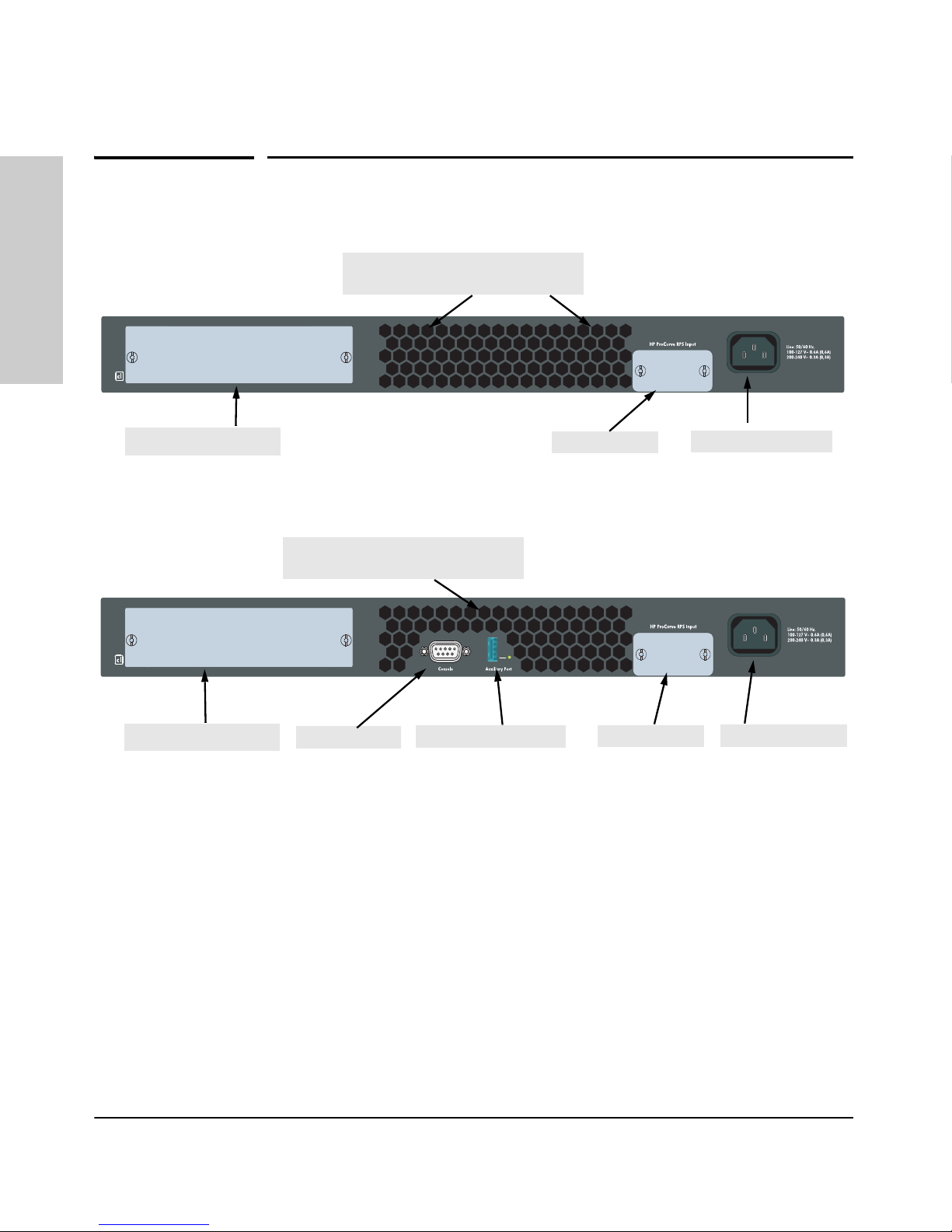
Back of the Switch
Back of the Switch
Cooling vents - make sure this is not
obstructed for proper switch operation
ProCurve Switch 3400cl-24G
Introducing the Switch
Optional cl module slot
Cooling vents - make sure this is not
obstructed for proper switch operation
RPS Input Port
ProCurve Switch 3400cl-48G
AC power connector
Optional cl module slot
1-10
Console Port
Auxiliary Port and LED
RPS Input Port
AC power connector
Console Port
This port is used to connect a console to the switch by using the serial cable
supplied with the switch. This connection is described under “Connect a
Console to the Switch” in chapter 2, “Installing the Switch.” The console can
be a PC or workstation running a VT-100 terminal emulator, or a VT-100
terminal. The console port is located on the front of the 3400cl-24G and on the
back of the 3400cl-48G.
Power Connector
The Series 3400cl Switch devices do not have a power switch; they are
powered on when connected to an active AC power source. These switches
automatically adjust to any voltage between 100--127 and 200--240 volts and
either 50 or 60 Hz. There are no voltage range settings required.

Introducing the Switch
Switch Features
Switch Features
The features of the Series 3400cl Switch devices include:
■ 24 or 48 auto-sensing 10/1001000Base-T RJ-45 ports with HP Auto-MDIX.
■ four dual-personality ports—either the auto sensing 10/100/1000Base-T
RJ-45 or the mini-GBIC can be used for each port.
■ one slot (optional cl module slot) is provided in the back of the device to
support a series of transceivers to provide box connectivity to other
switch boxes, to a 10 Gig concentrator or to any Ethernet compatible
uplink.
■ one auxiliary port is provided.
■ The Series 3400cl Switch devices can be connected to a ProCurve
RPS/EPS (J8168A) and receive full redundant power from that unit. If the
internal power supply in the switch fails, the RPS/EPS unit will immediately provide all the power necessary to keep the switch running.
■ plug-and-play networking—all ports are enabled—just connect the
network cables to active network devices and your switched network is
operational.
■ IEEE 802.3ab Auto MDI/MDI-X on all 10/100/1000-T twisted-pair ports,
meaning that all connections can be made using straight-through
twisted-pair cables. Cross-over cables are not required, although they
will also work. The pin operation of each port is automatically adjusted
for the attached device: if the switch detects that another switch or hub
is connected to the port, it configures the port as MDI; if the switch detects
that an end-node device is connected to the port, it configures the port as
MDI-X.
■ automatic learning of the network addresses in each switch’s 8000-
address forwarding table, (with configurable address aging value).
■ automatically negotiated full-duplex operation for the 10/100/1000-T RJ-
45 ports when connected to other auto-negotiating devices—the miniGBIC ports always operate at full duplex.
■ easy management of the switch through several available interfaces:
• console interface—a full featured, easy to use, VT-100 terminal
interface that is especially good for out-of-band switch management
or for Telnet access to the switch.
• web browser interface—an easy to use built-in graphical interface
that can be accessed from common web browsers.
• ProCurve Manager—an SNMP-based, graphical network management tool that you can use to manage your entire network. This
product is included with your new switch.
Introducing the Switch
1-11

Introducing the Switch
Switch Features
■ support for the Spanning Tree Protocol to eliminate network loops
■ support for up to 30 IEEE 802.1Q-compliant VLANs so you can divide the
attached end nodes into logical groupings that fit your business needs.
■ support for many advanced features to enhance network performance—
for a description, see the Management and Configuration Guide, which
is on the Documentation CD-ROM that is included with your switch.
■ download of new switch software for product enhancements or bug fixes.
Introducing the Switch
1-12

Installing the Switch
The ProCurve Series 3400cl Switch devices come with an accessory kit that
includes the brackets for mounting the switch in a standard 19-inch telco rack,
in an equipment cabinet, and with rubber feet that can be attached so the
switch can be securely located on a horizontal surface. The brackets are
designed to allow mounting the switch in a variety of locations and orientations. This chapter shows how to install the switch.
Included Parts
The Series 3400cl Switch devices have the following components shipped with
them:
■ ProCurve Series 3400cl Switch Installation and Getting Started Guide,
this manual
■ ProCurve Product Documentation CD ROM
(contains PDF file copies of the documentation for the Series 3400cl
Switch devices, including the Management and Configuration Guide,
and for most other ProCurve switches)
■ ProCurve Manager - CD ROM and booklet
■ Read Me First
■ Customer Support/Warranty booklet
■ Console cable
■ Accessory kits
2
Installing the Switch
(5064-2085) for Switch
3400cl-24G
two mounting brackets two mounting brackets*
four 8-mm M4 screws to attach the mounting
brackets to the switch
four 5/8-inch number 12-24 screws to attach
the switch to a rack
four rubber feet four rubber feet
* These mounting brackets differ from the 5064-2085 mounting brackets by being longer to
support the increased depth of the 3400cl-48G product (compared to the 3400cl-24G).
(5069-5705) for Switch
3400cl-48G
eight 8-mm M4 screws to attach the
mounting brackets to the switch
four 5/8-inch number 12-24 screws to
attach the switch to a rack
2-1

Installing the Switch
Included Parts
■ Power cord, one of the following:
Installing the Switch
Japan Power
Cord Warning
Australia/New Zealand
China
Continental Europe
Denmark
Japan
Switzerland
United Kingdom/Hong Kong/Singapore
United States/Canada/Mexico
8120-6803
8120-8377
8120-6802
8120-6806
8120-6804
8120-6807
8120-8709
8120-6805
Please use the power cord supplied with your product. This power cord
is not to be used with other products.
2-2

Installing the Switch
Installation Procedures
Installation Procedures
Summary
1. Prepare the installation site (page 2-5). Ensure the physical environment is properly prepared, including having the correct network cabling
ready to connect to the switch and having an appropriate location for the
switch. See page 2-4 for some installation precautions.
2. Install a cl module (optional—page 2-7).
3. Install a transceiver (optional—(page 2-8). If you have installed a
media flex cl module, you can now install one or two transceivers.
4. Install mini-GBICs (optional—page 2-9). The switch has four slots for
installing mini-GBICs. Depending on where you will mount the switch, it
may be easier to install the mini-GBICs first. Mini-GBICs can be installed
or removed while the switch is powered on.
5. Verify the switch passes self test (page 2-11). Plug the switch into a
power source and observe that the LEDs on the switch’s front panel
indicate correct switch operation. When self test is complete, unplug the
switch.
6. Mount the switch (page 2-13). The Switch can be mounted in a 19-inch
telco rack, in an equipment cabinet, or on a horizontal surface.
7. Connect power to the switch (page 2-19). Once the switch is mounted,
plug it into the nearby main power source.
8. Connect the network cables (page 2-20). Using the appropriate
network cables, connect the network devices to the switch ports.
9. Connect a Redundant Power Supply (RPS), (optional—page 2-21).
You may wish to use the RPS option with your Switch. Connect the RPS
using the cables supplied with the RPS, to the back of the switch.
Installing the Switch
10. Connect a console to the switch (optional—page 2-24). You may wish
to modify the switch’s configuration, for example, to configure an IP
address so it can be managed using a web browser, from an SNMP network
management station, or through a Telnet session. Configuration changes
can be made easily by using the included console cable to connect a PC
to the switch’s console port.
At this point, the switch is fully installed. See the rest of this chapter if you
need more detailed information on any of these installation steps.
2-3

Installing the Switch
Installing the Switch
Installation Procedures
Installation Precautions:
Follow these precautions when installing the Series 3400cl Switch devices.
WARNING ■ The rack or cabinet should be adequately secured to prevent it
from becoming unstable and/or falling over.
Devices installed in a rack or cabinet should be mounted as low as
possible, with the heaviest devices at the bottom and progressively
lighter devices installed above.
■ For safe operation, do not install the switch with the back face of
the switch (with the fan vents) facing either downward or upward.
■ Left side vents cannot be placed downward. (That is, the left side
of the unit while facing the front.)
Cautions ■ Ensure the power source circuits are properly grounded, then use the
power cord supplied with the switch to connect it to the power source.
■ If your installation requires a different power cord than the one supplied
with the switch, be sure to use a power cord displaying the mark of the
safety agency that defines the regulations for power cords in your country.
The mark is your assurance that the power cord can be used safely with
the switch.
■ When installing the switch, the AC outlet should be near the switch and
should be easily accessible in case the switch must be powered off.
■ Ensure the switch does not overload the power circuits, wiring, and over-
current protection. To determine the possibility of overloading the supply
circuits, add together the ampere ratings of all devices installed on the
same circuit as the switch and compare the total with the rating limit for
the circuit. The maximum ampere ratings are usually printed on the
devices near the AC power connectors.
■ Do not install the switch in an environment where the operating ambient
temperature might exceed 55°C (131°F)
■ Ensure the air flow around the sides and back of the switch is not
1
.
restricted.
1
If you are installing either of the Series 3400cl Switch devices using one of the fiber transceivers,
the operating ambient temperature should not exceed 40°C (104°F). See transceiver
specifications in the ProCurve Switch cl Modules Installation Guide.
2-4

1. Prepare the Installation Site
■ Cabling Infrastructure - Ensure the cabling infrastructure meets the
necessary network specifications. See the following table for cable types
and lengths, and see Appendix B “Switch Ports and Network Cables” for
more information:
Table 2-1. Summary of Cable Types to Use With the Switch
Port Type Cable Type Length Limits
Twisted-Pair Cables
Installing the Switch
Installation Procedures
10/100/1000Base-T For either 10, 100 Mbps, or 1000 Mbps
operation:
Category 5 or better, 100-ohm UTP or shielded
twisted-pair (STP) balanced cable. For
1000 Mbps (gigabit) operation, Category 5e
cabling or better is recommended.
100 meters
Note: The Series 3400cl Switch devices are
compatible with the IEEE 802.3ab standard
including the “Auto MDI/MDI-X” feature,
which allows use of either straight-through or
crossover twisted-pair cables for connecting
to any network devices including end nodes,
such as computers, or to other switches, hubs,
and routers.
Note: For 1000 Mbps operation, all four wire
pairs are used for data transmission.
Installing the Switch
2-5

Installing the Switch
Installation Procedures
Port Type Cable Type Length Limits
Fiber Optic Cables
Installing the Switch
Gigabit-SX
(on Gigabit-SX-LC
mini-GBIC)
Gigabit-LX
(on Gigabit-LX-LC
mini-GBIC)
Gigabit-LH
(on Gigabit-LH-LC
mini-GBIC)
Multimode fiber-optic cables designed for
Gigabit Ethernet: 62.5/125 µm or 50/125 µm
(core/cladding) diameter, 850 nm, low metal
content, graded-index cables, fitted with LC
connectors. The cables must comply with the
ITU-T G.651 and ISO/IEC 793-2 Type A1b or A1a
standards.
Single-mode fiber-optic cables designed for
Gigabit Ethernet: 9/125 µm (core/cladding)
diameter, 1310 nm, low metal content cables,
fitted with LC connectors. The cables must
comply with the ITU-T G.652 and ISO/IEC 793-2
Type B1 standards.
The multimode cables specified for the GigabitSX mini-GBIC may also be used, but a modeconditioning patch cord may be needed — see
“Mode Conditioning Patch Cord for Gigabit-LX”
on page B-3 for more information.
Single-mode fiber-optic cables designed for
Gigabit Ethernet and fitted with LC connectors.
• 62.5 µm cable:
– 160 MHz*km = 220 meters
– 200 MHz*km = 275 meters
•50 µm cable:
– 400 MHz*km = 500 meters
– 500 MHz*km = 550 meters
• single-mode cable = 5 kilometers
• multimode cable = 550 meters
• single-mode cable = 70 kilometers
2-6
■ Installation Location - Before installing the switch, plan its location and
orientation relative to other devices and equipment:
• In the front of the switch, leave at least 7.6 cm (3 inches) of space for
the twisted-pair and fiber-optic cabling.
• In the back of the switch, leave at least 3.8 cm (1 1/2 inches) of space
for the power cord.
• On the sides of the switch, leave at least 7.6 cm (3 inches) for cooling,
except if the switch is installed in an open EIA/TIA rack.
Installing the Switch
Installation Procedures
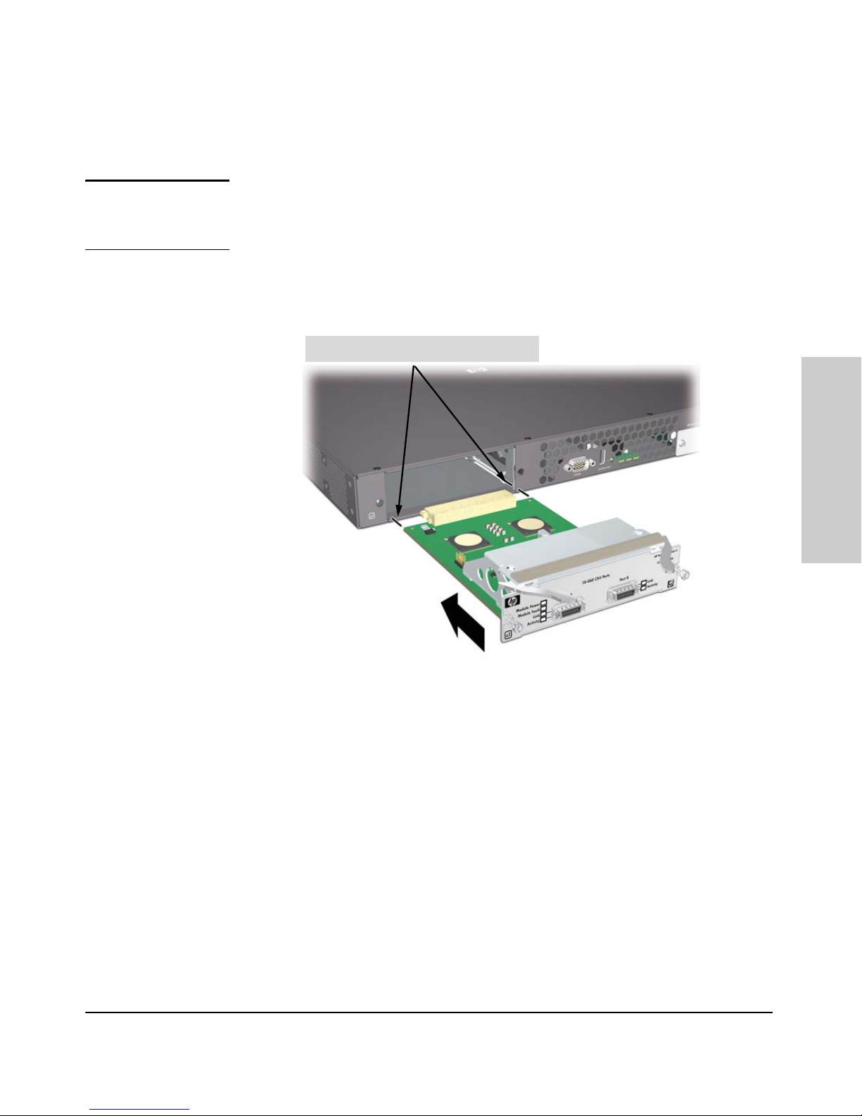
2. (Optional) Install or Remove a cl Module
Note Hot swapping modules is not supported. If a module is installed or removed
with the switch powered on, a reset will occur. Only insert or remove a module
during scheduled downtime with the switch powered off.
1. Remove the cover plate
Align the edges of the board with guides
Installing the Switch
2. Insert the module aligning with the guides in the slot.
3. Once the contacts have engaged, use the extractor handles to seat the
module completely.
4. Tighten the captive screws.
Refer to the cl Module Installation Guide for more details.
If you have installed a media flex module, you can now install a transceiver.
See the following step.
2-7
Installing the Switch
Installation Procedures
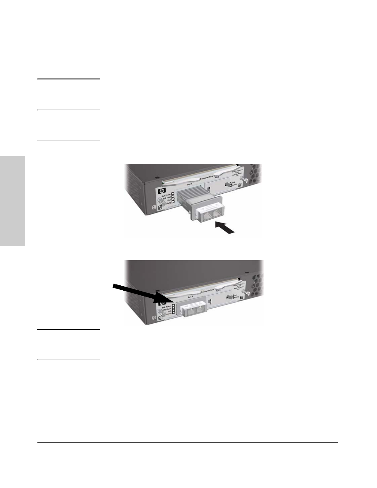
3. (Optional) Install or Remove a Transceiver
Note Hot swapping transceivers is supported. You can install or remove a trans-
ceiver with the switch powered on, a reset will not occur.
WARNING The ProCurve X2 fiber optic transceivers are Class 1 or Class 1M laser
devices. Avoid direct eye exposure to the beam coming from the
transmit port.
a. Slide the transceiver in until it stops.
Installing the Switch
b. Push firmly until the gasket seats against the bulkhead.
Note When switch power is on, the Link and Activity LEDs will come on for
approximately two seconds and then go off. This is confirmation the transceiver is completely seated.
c. If your transceiver has a bail, move the bail up, if not your transceiver is
now completely installed.
Refer to the ProCurve Switch cl Modules Installation Guide for more details.
To remove the transceiver:
If your transceiver has a bail, lower the bail until it is approximately horizontal,
and then using the bail, pull the transceiver from the slot. If your transceiver
does not have a bail, pull the transceiver straight out.
2-8

Installing the Switch
Installation Procedures
4. (Optional) Install or Remove mini-GBICs
You can install or remove a mini-GBIC from a mini-GBIC slot without having
to power off the switch. Use only ProCurve mini-GBICs.
Notes ■ The mini-GBIC slots are shared with the four 10/100/1000Base-T RJ-45
ports. If a mini-GBIC is installed in a slot, the associated RJ-45 port is
disabled and cannot be used.
■ The mini-GBIC ports operate only at full duplex. Half duplex operation is
not supported.
■ Ensure the network cable is NOT connected when you install or remove
a mini-GBIC.
When this manual was printed, the supported mini-GBICs include the
following:
■ ProCurve Gigabit-SX-LC mini-GBIC (J4858B)
■ ProCurve Gigabit-LX-LC mini-GBIC (J4859B)
■ ProCurve Gigabit-LH-LC mini-GBIC (J4860B)
Installing the Switch
Caution Use only supported genuine ProCurve mini-GBICs with your switch. Non-
ProCurve mini-GBICs are not supported, and their use may result in product
malfunction. Should you require additional ProCurve mini-GBICs, contact
your ProCurve Networking Sales and Service Office or authorized dealer.
Installing the mini-GBICs:
Hold the mini-GBIC by its sides and gently insert it into either of the slots on
the switch until the mini-GBIC clicks into place.
WARNING The ProCurve mini-GBICs are Class 1 laser devices. Avoid direct eye
exposure to the beam coming from the transmit port.
2-9

Installing the Switch
Installation Procedures
Removing the mini-GBICs:
Note You should disconnect the network cable from the mini-GBIC before removing
it from the switch.
Depending on when you purchased your ProCurve mini-GBIC, it may have
either of three different release mechanisms: a plastic tab on the bottom of
the mini-GBIC, a plastic collar around the mini-GBIC, or a wire bail.
To remove the mini-GBICs that have the plastic tab or plastic collar, push the
tab or collar toward the switch until you see the mini-GBIC release from the
switch (you can see it move outward slightly), and then pull it from the slot.
To remove the mini-GBICs that have the wire bail, lower the bail until it is
approximately horizontal, and then using the bail, pull the mini-GBIC from the
slot.
Installing the Switch
2-10
 Loading...