

HP J9146A, ProCurve 2910al Installation And Getting Started Manual

Power over Ethernet
ProCurve 2910al Switches
Installation and Getting Started Guide


ProCurve 2910al Switches
Installation and Getting Started Guide

© Copyright 2009-2010 Hewlett-Packard Development
Company, L.P.
Publication Number
5992-3084
March 2010
Applicable Products
HP ProCurve 2910al-24G Switch (J9145A)
HP ProCurve 2910al-48G Switch (J9147A)
HP ProCurve 2910al-24G-PoE+ Switch (J9146A)
HP ProCurve 2910al-48G-PoE+ Switch (J9148A)
HP ProCurve 2-Port 10-GbE CX4 al Module (J9149A)
HP ProCurve 2-Port 10-GbE SFP+ al Module (J9008A)
HP ProCurve 10-GbE al Interconnect Kit (J9165A)
HP ProCurve 620 Redundant and
(J8696A)
External Power Supply
HP ProCurve 630 Redundant and/or
(J9443A)
External Power Supply
Disclaimer
HEWLETT-PACKARD COMPANY MAKES NO WARRANTY
OF ANY KIND WITH REGARD TO THIS MATERIAL,
INCLUDING, BUT NOT LIMITED TO, THE IMPLIED
WARRANTIES OF MERCHANTABILITY AND FITNESS
FOR A PARTICULAR PURPOSE. Hewlett-Packard shall not
be liable for errors contained herein or for incidental or
consequential damages in connection with the furnishing,
performance, or use of this material.
The information contained herein is subject to change
without notice. The only warranties for HP products and
services are set forth in the express warranty statements
accompanying such products and services. Nothing herein
should be construed as constituting an additional warranty.
HP shall not be liable for technical or editorial errors or
omissions contained herein.
Hewlett-Packard assumes no responsibility for the use or
reliability of its software on equipment that is not furnished
by Hewlett-Packard.
Warra nty
See the Customer Support/Warranty booklet included with
the product.
A copy of the specific warranty terms applicable to your
Hewlett-Packard products and replacement parts can be
obtained from your HP Sales and Service Office or
authorized dealer.
Hewlett-Packard Company
8000 Foothills Boulevard, m/s 5552
Roseville, California 95747-5552
http://www.hp.com/go/procurve
Safety
Before installing and operating these products, please read
the “Installation Precautions” in chapter 2, “Installing the
Switch”, and the safety statements in appendix C, “Safety
and EMC Regulatory Statements”.

Contents
1 Introducing the Switch
Front of the Switch . . . . . . . . . . . . . . . . . . . . . . . . . . . . . . . . . . . . . . . . . . . . . . 1-4
Network Ports . . . . . . . . . . . . . . . . . . . . . . . . . . . . . . . . . . . . . . . . . . . . . . 1-6
LEDs . . . . . . . . . . . . . . . . . . . . . . . . . . . . . . . . . . . . . . . . . . . . . . . . . . . . . . 1-6
LED Mode Select Button and Indicator LEDs . . . . . . . . . . . . . . . . . . . . 1-8
Reset Button . . . . . . . . . . . . . . . . . . . . . . . . . . . . . . . . . . . . . . . . . . . . . . 1-10
Clear Button . . . . . . . . . . . . . . . . . . . . . . . . . . . . . . . . . . . . . . . . . . . . . . . 1-10
Console Port . . . . . . . . . . . . . . . . . . . . . . . . . . . . . . . . . . . . . . . . . . . . . . 1-11
Expansion Module LEDs . . . . . . . . . . . . . . . . . . . . . . . . . . . . . . . . . . . . 1-11
Back of the Switch . . . . . . . . . . . . . . . . . . . . . . . . . . . . . . . . . . . . . . . . . . . . . 1-12
al Module Slots . . . . . . . . . . . . . . . . . . . . . . . . . . . . . . . . . . . . . . . . . . . . 1-12
RPS and EPS Input Ports . . . . . . . . . . . . . . . . . . . . . . . . . . . . . . . . . . . 1-13
Power Connector . . . . . . . . . . . . . . . . . . . . . . . . . . . . . . . . . . . . . . . . . . 1-13
HP ProCurve Switch al Modules . . . . . . . . . . . . . . . . . . . . . . . . . . . . . . . . . 1-14
Features . . . . . . . . . . . . . . . . . . . . . . . . . . . . . . . . . . . . . . . . . . . . . . . . . . . . . . 1-15
Switch Features . . . . . . . . . . . . . . . . . . . . . . . . . . . . . . . . . . . . . . . . . . . . . . . 1-16
2 Installing the Switch
Included Parts . . . . . . . . . . . . . . . . . . . . . . . . . . . . . . . . . . . . . . . . . . . . . . . . . . 2-1
Installation Precautions: . . . . . . . . . . . . . . . . . . . . . . . . . . . . . . . . . . . . . . 2-3
Installation Procedures . . . . . . . . . . . . . . . . . . . . . . . . . . . . . . . . . . . . . . . . . . 2-4
Summary . . . . . . . . . . . . . . . . . . . . . . . . . . . . . . . . . . . . . . . . . . . . . . . . . . . 2-4
1. Prepare the Installation Site . . . . . . . . . . . . . . . . . . . . . . . . . . . . . . . . 2-5
2. Verify the Switch Passes Self Test . . . . . . . . . . . . . . . . . . . . . . . . . . . 2-5
LED Behavior: . . . . . . . . . . . . . . . . . . . . . . . . . . . . . . . . . . . . . . . . . . 2-7
3. (Optional) Install a Module . . . . . . . . . . . . . . . . . . . . . . . . . . . . . . . . . 2-8
Installing the Interconnect Kit . . . . . . . . . . . . . . . . . . . . . . . . . . . . . 2-9
Verifying the Module is Installed Correctly . . . . . . . . . . . . . . . . . 2-10
iii

4. Mount the Switch . . . . . . . . . . . . . . . . . . . . . . . . . . . . . . . . . . . . . . . . 2-11
Rack or Cabinet Mounting . . . . . . . . . . . . . . . . . . . . . . . . . . . . . . . 2-11
Rack Mounting the Switch . . . . . . . . . . . . . . . . . . . . . . . . . . . . . . . 2-11
Horizontal Surface Mounting . . . . . . . . . . . . . . . . . . . . . . . . . . . . . 2-13
5. (Optional) Install a Transceiver . . . . . . . . . . . . . . . . . . . . . . . . . . . . 2-14
To remove the transceiver: . . . . . . . . . . . . . . . . . . . . . . . . . . . . . . . 2-14
Installing or Removing the Optical Media Converter . . . . . . . . . 2-15
6. (Optional) Install Mini-GBICs and SFPs . . . . . . . . . . . . . . . . . . . . . . 2-16
Removing the mini-GBICs . . . . . . . . . . . . . . . . . . . . . . . . . . . . . . . . 2-17
7. Connect the Switch to a Power Source . . . . . . . . . . . . . . . . . . . . . . 2-18
8. (Optional) Connect an External Power Supply . . . . . . . . . . . . . . . . 2-18
RPS Operation . . . . . . . . . . . . . . . . . . . . . . . . . . . . . . . . . . . . . . . . . 2-18
Operating Characteristics of the 620 RPS/EPS (J8696A) . . . . . . 2-19
620 RPS/EPS Connectivity . . . . . . . . . . . . . . . . . . . . . . . . . . . . . . . 2-21
Operating characteristics of the HP ProCurve 630 RPS/EPS (J9443A)
2-22
HP ProCurve 630 RPS/EPS Connectivity . . . . . . . . . . . . . . . . . . . 2-24
9. (Optional) Connect a Console to the Switch . . . . . . . . . . . . . . . . . . 2-24
Terminal Configuration . . . . . . . . . . . . . . . . . . . . . . . . . . . . . . . . . . 2-25
Direct Console Access . . . . . . . . . . . . . . . . . . . . . . . . . . . . . . . . . . . 2-25
Console Cable Pinouts . . . . . . . . . . . . . . . . . . . . . . . . . . . . . . . . . . 2-26
10. Connect the Network Cables . . . . . . . . . . . . . . . . . . . . . . . . . . . . . . 2-27
Using the RJ-45 Connectors . . . . . . . . . . . . . . . . . . . . . . . . . . . . . . 2-27
Connecting Cables to mini-GBICs . . . . . . . . . . . . . . . . . . . . . . . . . 2-27
Connecting a fiber cable . . . . . . . . . . . . . . . . . . . . . . . . . . . . . . . . . 2-28
Connecting a copper cable . . . . . . . . . . . . . . . . . . . . . . . . . . . . . . . 2-28
iv
Sample Network Topologies . . . . . . . . . . . . . . . . . . . . . . . . . . . . . . . . . . . . . 2-29
3 Getting Started With Switch Configuration
Recommended Minimal Configuration . . . . . . . . . . . . . . . . . . . . . . . . . . . . . 3-1
Using the Console Setup Screen . . . . . . . . . . . . . . . . . . . . . . . . . . . . . . . . . . . 3-2
Where to Go From Here . . . . . . . . . . . . . . . . . . . . . . . . . . . . . . . . . . . . . . . . . 3-4
To Recover from a Lost Manager Password . . . . . . . . . . . . . . . . . . . . . 3-4
Using the IP Address for Remote Switch Management . . . . . . . . . . . . . . . . 3-5
Starting a Telnet Session . . . . . . . . . . . . . . . . . . . . . . . . . . . . . . . . . . . . . 3-5
Starting a Web Browser Session . . . . . . . . . . . . . . . . . . . . . . . . . . . . . . . 3-5

4 Troubleshooting
Basic Troubleshooting Tips . . . . . . . . . . . . . . . . . . . . . . . . . . . . . . . . . . . . . . 4-1
Diagnosing with the LEDs . . . . . . . . . . . . . . . . . . . . . . . . . . . . . . . . . . . . . . . . 4-4
Proactive Networking . . . . . . . . . . . . . . . . . . . . . . . . . . . . . . . . . . . . . . . . . . . 4-8
Hardware Diagnostic Tests . . . . . . . . . . . . . . . . . . . . . . . . . . . . . . . . . . . . . . . 4-9
Testing the Switch by Resetting It . . . . . . . . . . . . . . . . . . . . . . . . . . . . . 4-9
Checking the Switch LEDs . . . . . . . . . . . . . . . . . . . . . . . . . . . . . . . . 4-9
Checking Console Messages . . . . . . . . . . . . . . . . . . . . . . . . . . . . . . . 4-9
Testing Twisted-Pair Cabling . . . . . . . . . . . . . . . . . . . . . . . . . . . . . . . . . 4-10
Testing Switch-to-Device Network Communications . . . . . . . . . . . . 4-10
Testing End-to-End Network Communications . . . . . . . . . . . . . . . . . 4-10
Restoring the Factory Default Configuration . . . . . . . . . . . . . . . . . . . . . . . 4-11
Downloading New Switch Software . . . . . . . . . . . . . . . . . . . . . . . . . . . . . . 4-12
HP Customer Support Services . . . . . . . . . . . . . . . . . . . . . . . . . . . . . . . . . . 4-12
Before Calling Support . . . . . . . . . . . . . . . . . . . . . . . . . . . . . . . . . . . . . . 4-12
A Switch Specifications
Physical . . . . . . . . . . . . . . . . . . . . . . . . . . . . . . . . . . . . . . . . . . . . . . . . . . . A-1
Electrical . . . . . . . . . . . . . . . . . . . . . . . . . . . . . . . . . . . . . . . . . . . . . . . . . A-1
Environmental . . . . . . . . . . . . . . . . . . . . . . . . . . . . . . . . . . . . . . . . . . . . . A-1
Acoustic . . . . . . . . . . . . . . . . . . . . . . . . . . . . . . . . . . . . . . . . . . . . . . . . . . A-2
Safety . . . . . . . . . . . . . . . . . . . . . . . . . . . . . . . . . . . . . . . . . . . . . . . . . . . . A-2
B Module Specifications
Physical . . . . . . . . . . . . . . . . . . . . . . . . . . . . . . . . . . . . . . . . . . . . . . . . . . . B-1
Environmental . . . . . . . . . . . . . . . . . . . . . . . . . . . . . . . . . . . . . . . . . . . . . B-1
Optical Power Specifications . . . . . . . . . . . . . . . . . . . . . . . . . . . . . . . . . B-1
C Cabling and Technology Information
Cabling specifications . . . . . . . . . . . . . . . . . . . . . . . . . . . . . . . . . . . . . . . C-1
Technology distance specifications . . . . . . . . . . . . . . . . . . . . . . . . . . . C-3
Mode Conditioning Patch Cord . . . . . . . . . . . . . . . . . . . . . . . . . . . . . . . C-4
v

Installing the Patch Cord . . . . . . . . . . . . . . . . . . . . . . . . . . . . . . . . . . . . C-5
Twisted-Pair Cable/Connector Pin-Outs . . . . . . . . . . . . . . . . . . . . . . . C-6
Straight-Through Twisted-Pair Cable for
10 Mbps or 100 Mbps Network Connections . . . . . . . . . . . . . . . . . . . . C-7
Cable Diagram . . . . . . . . . . . . . . . . . . . . . . . . . . . . . . . . . . . . . . . . . C-7
Pin Assignments . . . . . . . . . . . . . . . . . . . . . . . . . . . . . . . . . . . . . . . . C-7
Crossover Twisted-Pair Cable for
10 Mbps or 100 Mbps Network Connection . . . . . . . . . . . . . . . . . . . . . C-8
Cable Diagram . . . . . . . . . . . . . . . . . . . . . . . . . . . . . . . . . . . . . . . . . C-8
Pin Assignments . . . . . . . . . . . . . . . . . . . . . . . . . . . . . . . . . . . . . . . . C-8
Straight-Through Twisted-Pair Cable for
1000 Mbps Network Connections . . . . . . . . . . . . . . . . . . . . . . . . . . . . . C-9
Cable Diagram . . . . . . . . . . . . . . . . . . . . . . . . . . . . . . . . . . . . . . . . . C-9
Pin Assignments . . . . . . . . . . . . . . . . . . . . . . . . . . . . . . . . . . . . . . . . C-9
D Safety and EMC Regulatory Statements
Safety Information . . . . . . . . . . . . . . . . . . . . . . . . . . . . . . . . . . . . . . . . . . . . . D-1
Informations concernant la sécurité . . . . . . . . . . . . . . . . . . . . . . . . . . . . . . D-2
Hinweise zur Sicherheit . . . . . . . . . . . . . . . . . . . . . . . . . . . . . . . . . . . . . . . . . D-3
Considerazioni sulla sicurezza . . . . . . . . . . . . . . . . . . . . . . . . . . . . . . . . . . . D-4
Consideraciones sobre seguridad . . . . . . . . . . . . . . . . . . . . . . . . . . . . . . . . D-5
Safety Information (Japan) . . . . . . . . . . . . . . . . . . . . . . . . . . . . . . . . . . . . . . D-6
Safety Information (China) . . . . . . . . . . . . . . . . . . . . . . . . . . . . . . . . . . . . . . D-7
EMC Regulatory Statements . . . . . . . . . . . . . . . . . . . . . . . . . . . . . . . . . . . . . D-8
U.S.A. . . . . . . . . . . . . . . . . . . . . . . . . . . . . . . . . . . . . . . . . . . . . . . . . . . . . D-8
Canada . . . . . . . . . . . . . . . . . . . . . . . . . . . . . . . . . . . . . . . . . . . . . . . . . . . D-8
Australia/New Zealand . . . . . . . . . . . . . . . . . . . . . . . . . . . . . . . . . . . . . . D-8
Japan . . . . . . . . . . . . . . . . . . . . . . . . . . . . . . . . . . . . . . . . . . . . . . . . . . . . . D-8
Korea . . . . . . . . . . . . . . . . . . . . . . . . . . . . . . . . . . . . . . . . . . . . . . . . . . . . . D-9
Taiwan . . . . . . . . . . . . . . . . . . . . . . . . . . . . . . . . . . . . . . . . . . . . . . . . . . . D-9
European Community . . . . . . . . . . . . . . . . . . . . . . . . . . . . . . . . . . . . . . D-10
E Recycle Statements
Waste Electrical and Electronic Equipment (WEEE) Statements . . . . . . E-1
Index
vi
Introducing the Switch
Introducing the Switch
Power
Fault
Locator
Console
Spd mode: off = 10 Mbps
2 flash = 100 Mbps
on = 1 Gbps
3 flash = 10 Gbps
*
LED
Mode
Clear
Reset
10/100/1000Base-T Ports (1 - 24T) Ports are Auto-MDIX
Test
Tmp
Status
Dual-Personality Ports: 10/100/1000-T (T) or SFP (S)
!
Use only one (T or S) for each Port
Fan
21S
23S
22S 24S
FDx
Spd
Act
*
14
16
19
17
15
13
18
20
Link
Mode
23T
21T
22T
24T
Link
Mode
Status of the Back
Mdl
RPS
ProCurve Switch
2910bl-24G
J9145A
Link Mode
Link Mode
12
108
6
4
2
119
7
5
31
Link
Mode
Link
Mode
Usr
Auxiliary Port
HP ProCurve 2910al-24G Switch (J9145A)
Power
Fault
Locator
Console
LED
Mode
Clear
Reset
10/100/1000Base-T Ports (1 - 48T) Ports are Auto-MDIX
Test
Tmp
Status
Dual-Personality Ports: 10/100/1000-T (T) or SFP (S)
!
Use only one (T or S) for each Port
Fan
45S
47S
46S 48S
*
Spd mode: off=10 Mbps, 2 flash=100 Mbps, on=1 Gbps, 3 flash=10 Gbps
FDx
Spd
Act
*
38
40
43
41
39
37
12
10
8
6
4
2
11
9
7
5
3
1
42
44
Link
Mode
Link
Mode
Link
Mode
47T
45T
46T
48T
Link
Mode
Status of the Back
Mdl
RPS
ProCurve Switch
2910bl-48G
J9147A
Link Mode
Link Mode
24
22
20
18
16
14
2321
1917
1513
Link
Mode
Link
Mode
36
34
32
30
28
26
3533
31
29
2725
Link
Mode
Link
Mode
Usr
HP ProCurve 2910al-48G Switch (J9147A)
Power
Fault
Locator
Console
Spd mode: off = 10 Mbps
2 flash = 100 Mbps
on = 1 Gbps
3 flash = 10 Gbps
*
LED
Mode
Clear
Reset
PoE+ Integrated 10/100/1000Base-T Ports (1 - 24T) Ports are Auto-MDIX
Test
Tmp
Status
Dual-Personality Ports: 10/100/1000-T (T) or SFP (S)
!
Use only one (T or S) for each Port
PoE
Fan
21S
23S
22S 24S
FDx
Spd
PoE
Act
*
14
16
19
17
15
13
18
20
Link
Mode
23T
21T
22T
24T
Link
Mode
Status of the Back
Mdl
RPS
EPS
ProCurve Switch
2910bl-24G-PoE
J9146A
Link
Mode
Link Mode
12
108
6
4
2
119
7
5
31
Link
Mode
Link
Mode
Usr
Auxiliary Port
PoE+
HP ProCurve 2910al-24G-PoE+ Switch (J9146A)
Power
Fault
Locator
Console
LED
Mode
Clear
Reset
PoE+ Integrated 10/100/1000Base-T Ports (1 - 48T) Ports are Auto-MDIX
Test
Tmp
Status
Dual-Personality Ports: 10/100/1000-T (T) or SFP (S)
!
Use only one (T or S) for each Port
PoE
Fan
45S
47S
46S 48S
*
Spd mode: off=10 Mbps, 2 flash=100 Mbps, on=1 Gbps, 3 flash=10 Gbps
FDx
Spd
PoE
Act
*
38
40
43
41
39
37
12
10
8
6
4
2
11
9
7
5
3
1
42
44
Link
Mode
Link
Mode
Link
Mode
47T
45T
46T
48T
Link
Mode
Status of the Back
Mdl
RPS
EPS
ProCurve Switch
2910bl-48G-PoE
J9148A
Link
Mode
Link Mode
24
2220
18
16
14
2321
1917
1513
Link
Mode
Link
Mode
36
3432
30
28
26
3533
31
29
2725
Link
Mode
Link
Mode
Usr
PoE+
HP ProCurve 2910al-48G-PoE+ Switch (J9148A)
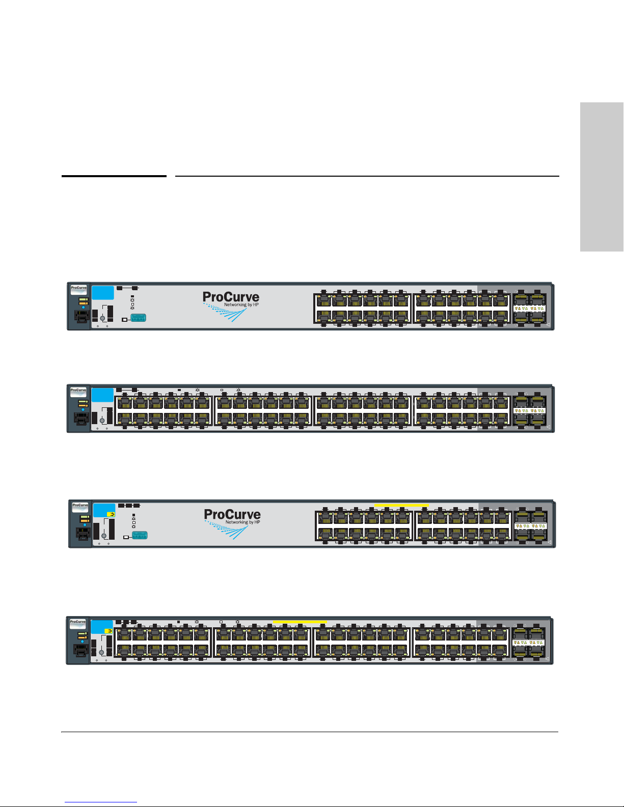
The HP ProCurve 2910al Switches are multiport switches that can be used to
build high-performance switched networks. These switches are store-andforward devices offering low latency for high-speed networking. The 2910al
switches also support Redundant Power Supply and Power over Ethernet
technologies.
1
Throughout this manual, these switches will be referred to as the 2910al
Switches or the 2910al-PoE+ Switches.
1-1

Introducing the Switch
Introducing the Switch
The 2910al-24G Switch and 2910al-48G Switch have respectively, 24 or 48,
auto-sensing 10/100/1000Base-T RJ-45 ports, four dual-personality ports—
either auto-sensing 10/100/1000Base-T RJ-45 or mini-GBIC, and two slots are
provided in the back of the device to support expansion modules:
■ 2-port (two fixed CX4 ports) 10 Gigabit per second Ethernet (10-GbE)
module.
■ 2-port 10-GbE SFP+ (Small Form Factor Pluggable) module. The specifi-
cation for SFP+ defines the physical and electrical characteristics of this
form-factor (size and shape). The form-factor is identical to SFP, but the
SFP+ is a 10-Gigabit Ethernet transceiver.
■ 1-port 10-GbE interconnect module.
Table 1-1. These products support optional network connectivity with the
following speeds and technologies:
Speed Technology Cabling Transceiver form-factor
and connector
SFP (mini-GBIC)
Connector
100-Mbps 100-FX Fiber (multimode) LC
100-BX Fiber (single mode) LC
1-Gbps 1000-SX Fiber (multimode) LC
1000-LX Fiber (multimode or
single mode)
1000-LH Fiber (single mode) LC
1000-BX Fiber (single mode) LC
10-Gbps CX4 Copper (twinaxial) N/A
10-Gig
Direct Attach
10-Gig SR Fiber (multimode) LC
10-Gig LRM Fiber (multimode) LC
10-Gig LR Fiber (single mode) LC
For supported transceivers see www.hp.com/go/procurve/faqs. Both ProCurve 10-GbE
transceivers and ProCurve Mini-GBICs and SFPs have links to a list of supported
products (first question in the “General Product Information” category).
Copper (twinaxial) N/A
LC
SFP+
Connector
For technical details of cabling and technologies see Appendix C, “Cabling and Technol-
ogy Information”.
1-2

Introducing the Switch
Introducing the Switch
The 2910al-PoE+ Switches also support Power over Ethernet+ (PoE+)
technology. PoE+ offers a higher wattage per port than the previous PoE
offering, 30 watts per port instead of 15. The switches support 802.3af standard
devices and some pre-standard PoE devices. It also supports the draft version
of the 802.3at standard. For a list of these devices, see the FAQs for your switch
model. This feature is the default and you must disable it if you do not want
to use it. Refer to the Management and Configuration Guide which is on the
ProCurve Web site at www.hp.com/go/procurve/manuals.
The dual-personality ports have either auto-sensing 10/100/1000Base-T RJ-45,
or mini-GBIC (SFP) connectivity. The mini-GBIC ports do not support PoE. If
any of the mini-GBIC ports are used the corresponding RJ-45 port will not be
supplied with PoE power and will be disabled. For more information regarding
the PoE capabilities of the 2910al Switches, see the ProCurve PoE (Power over
Ethernet) Devices Planning and Implementation Guide, which is on the
ProCurve Web site at www.hp.com/go/procurve/manuals.
HP ProCurve Redundant/External Power Supplies (RPS/EPS) can be
connected to the 2910al Switches for redundant 12 V system power (RPS) and
to provide for additional PoE+ provisioning. For RPS power, the 2910al
Switches can be connected to either an HP ProCurve 620 RPS/EPS or HP
ProCurve 630 Redundant and/or External Power Supply. But, for additional
PoE+ EPS power, only the HP ProCurve 630 RPS/EPS can be used. The 620
does not provide 54 V for PoE+, only 50 V for PoE, and the 2910al Switches do
not support connections to the 620 for EPS.
These switches are designed to be used primarily as a high-density wiring
closet or desktop switch. These switches can directly connect computers,
printers, and servers to provide dedicated bandwidth to those devices, and
can build a switched network infrastructure by connecting the switch to hubs,
other switches, or routers. In addition, the 2910al Switches offer full network
management capabilities.
This chapter describes the 2910al Switches, including:
■ Front and back of the switches
■ Network ports
■ LEDs
■ Switch features
1-3
Introducing the Switch
Introducing the Switch
Power
Fault
Locator
Console
Spd mode: off = 10 Mbps
2 flash = 100 Mbps
on = 1 Gbps
3 flash = 10 Gbps
*
LED
Mode
Clear
Reset
10/100/1000Base-T Ports (1 - 24T) Ports are Auto-MDIX
Test
Tmp
Status
Dual-Personality Ports: 10/100/1000-T (T) or SFP (S)
!
Use only one (T or S) for each Port
Fan
21S
23S
22S 24S
FDx
Spd
Act
*
14
16
19
17
15
13
18
20
Link
Mode
23T
21T
22T
24T
Link
Mode
Status of the Back
Mdl
RPS
ProCurve Switch
2910bl-24G
J9145A
Link
Mode
Link Mode
12
10
8
6
4
2
119
7
5
31
Link
Mode
Link
Mode
Usr
Auxiliary Port
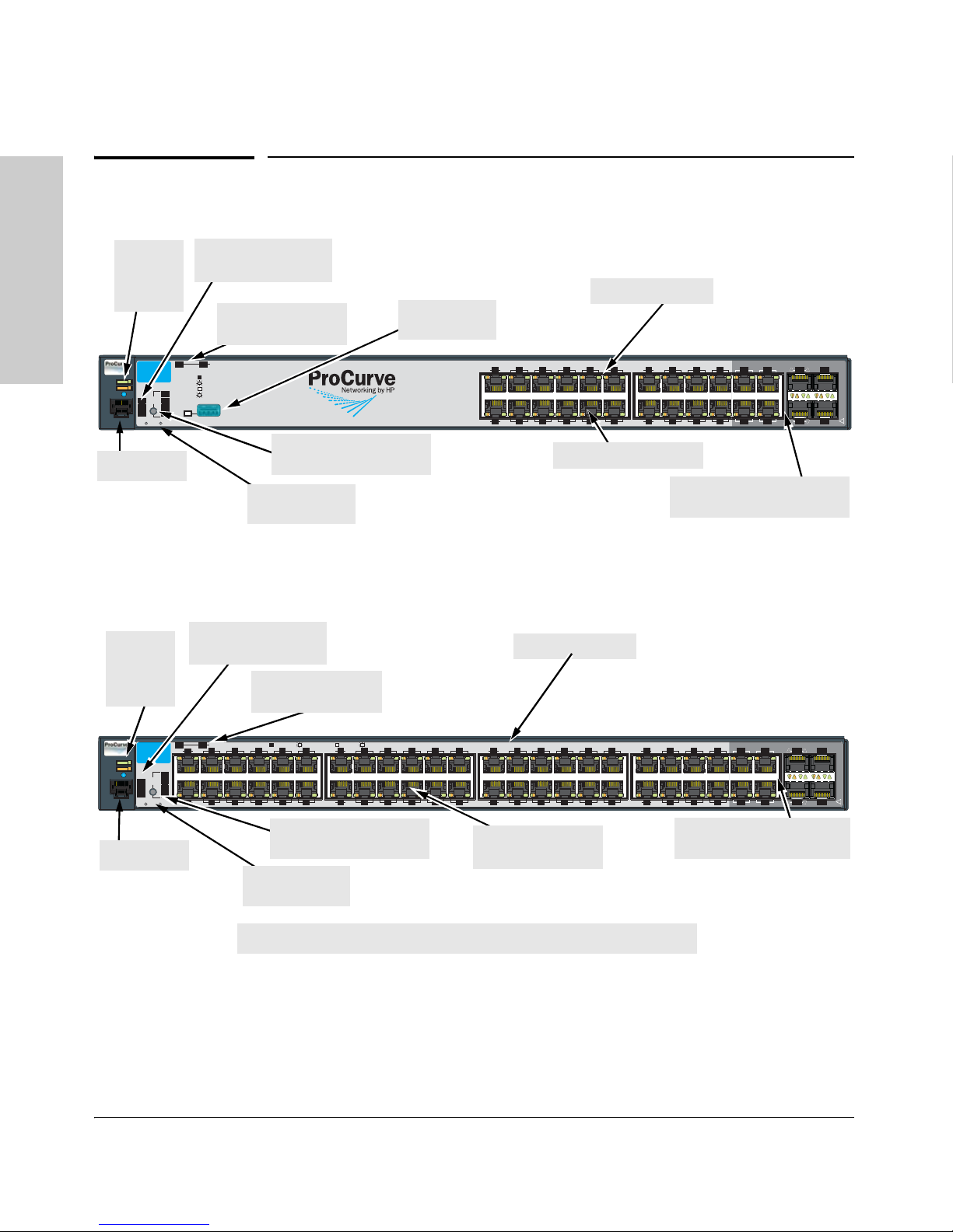
Power,
Fault, and
Locator
LEDs
Temp, Fan, and Test
Status LEDs
Module, and RPS,
Status LEDs
Auxiliary port
and LED*
10/100/1000Base-T RJ-45
Console port
Port LED Mode select
button and indicator LEDs
Reset and Clear
buttons
Switch port LEDs
Dual-personality ports
(1000Base-T or mini-GBIC)
Power
Fault
Locator
Console
LED
Mode
Clear
Reset
10/100/1000Base-T Ports (1 - 48T) Ports are Auto-MDIX
Test
Tmp
Status
Dual-Personality Ports: 10/100/1000-T (T) or SFP (S)
!
Use only one (T or S) for each Port
Fan
45S
47S
46S 48S
*
Spd mode: off=10 Mbps, 2 flash=100 Mbps, on=1 Gbps, 3 flash=10 Gbps
FDx
Spd
Act
*
38
40
43
41
39
37
12
10
8
6
4
2
11
9
7
5
3
1
42
44
Link
Mode
Link
Mode
Link
Mode
47T
45T
46T
48T
Link
Mode
Status of the Back
Mdl
RPS
ProCurve Switch
2910bl-48G
J9147A
Link Mode
Link Mode
24
2220
18
16
14
2321
1917
1513
Link
Mode
Link
Mode
36
3432
30
28
26
3533
31
29
2725
Link
Mode
Link
Mode
Usr
Switch port LEDs
Module, and RPS,
Status LEDs
PoE, Temp, Fan, and
Test Status LEDs
Power,
Fault, and
Locator
LEDs
10/100/1000Base-TX
RJ-45 ports
Port LED Mode select
button and indicator LEDs
Dual-personality ports
(1000Base-T or mini-GBIC)
Reset and Clear
buttons
Console port
*On the 2910al-48G switch, the Auxiliary port is located on the back of the unit.
Front of the Switch
Front of the Switch
Figure 1-1. HP ProCurve 2910al-24G Switch
Figure 1-2. HP ProCurve 2910al-48G Switch
1-4
Introducing the Switch
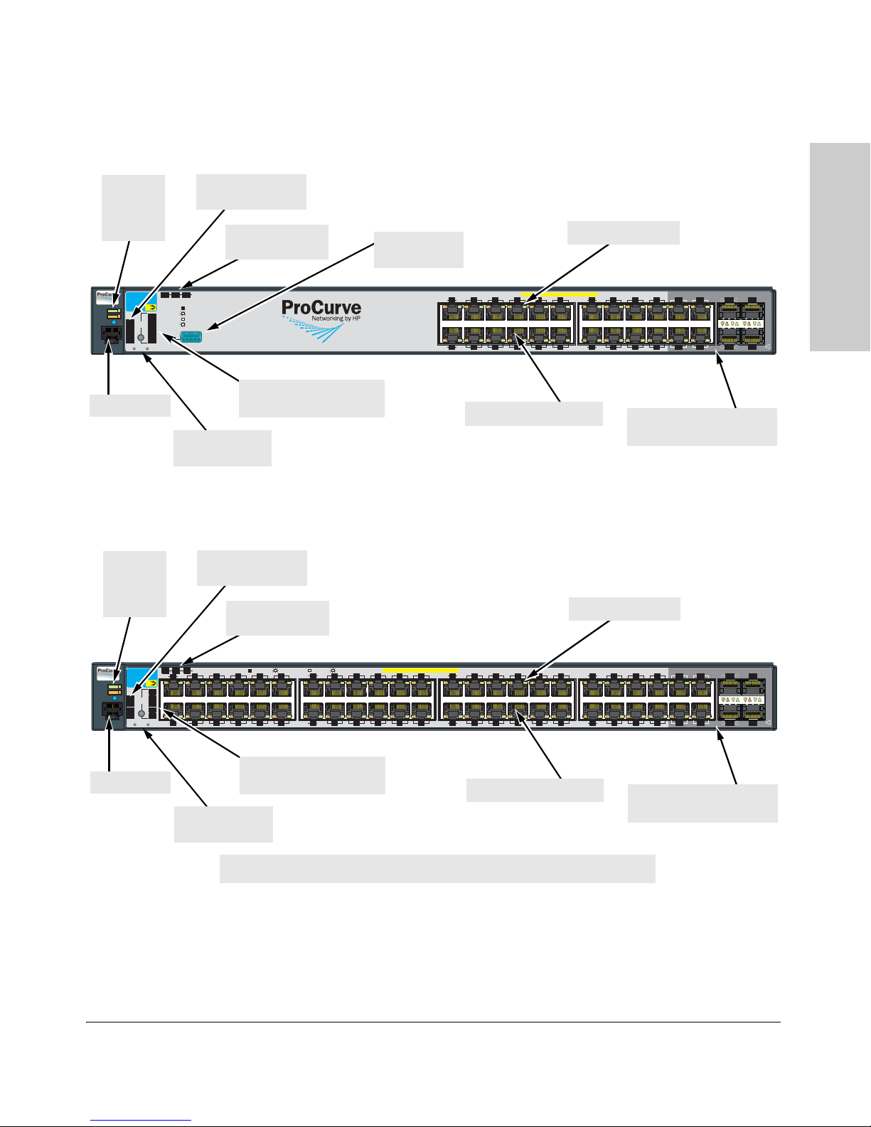
Figure 1-3. HP ProCurve 2910al-24G-PoE+ Switch
Power
Fault
Locator
Console
Spd mode: off = 10 Mbps
2 flash = 100 Mbps
on = 1 Gbps
3 flash = 10 Gbps
*
LED
Mode
Clear
Reset
PoE+ Integrated 10/100/1000Base-T Ports (1 - 24T) Ports are Auto-MDIX
Test
Tmp
Status
Dual-Personality Ports: 10/100/1000-T (T) or SFP (S)
!
Use only one (T or S) for each Port
PoE
Fan
21S
23S
22S 24S
FDx
Spd
PoE
Act
*
14
16
19
17
15
13
18
20
Link
Mode
23T
21T
22T
24T
Link
Mode
Status of the Back
Mdl RPS
EPS
ProCurve Switch
2910bl-24G-PoE
J9146A
Link
Mode
Link Mode
12
10
8
6
4
2
119
7
5
31
Link
Mode
Link
Mode
Usr
Auxiliary Port
PoE+
Reset and Clear
buttons
Port LED Mode select
button and indicator LEDs
Console port
Switch port LEDs
Module, EPS, and
RPS Status LEDs
PoE, Temp, Fan, and
Test Status LEDs
10/100/1000Base-T RJ-45
Dual-personality ports
(1000Base-T or mini-GBIC)
Power,
Fault, and
locator
LEDs
Auxiliary port
and LED*
Power
Fault
Locator
Console
LED
Mode
Clear
Reset
PoE+ Integrated 10/100/1000Base-T Ports (1 - 48T) Ports are Auto-MDIX
Test
Tmp
Status
Dual-Personality Ports: 10/100/1000-T (T) or SFP (S)
!
Use only one (T or S) for each Port
PoE
Fan
45S
47S
46S 48S
*
Spd mode: off=10 Mbps, 2 flash=100 Mbps, on=1 Gbps, 3 flash=10 Gbps
FDx
Spd
PoE
Act
*
38
40
43
41
39
37
12
10
8
6
4
2
11
9
7
5
3
1
42
44
Link
Mode
Link
Mode
Link
Mode
47T
45T
46T
48T
Link
Mode
Status of the Back
Mdl
RPS
EPS
ProCurve Switch
2910bl-48G-PoE
J9148A
Link
Mode
Link Mode
24
2220
18
16
14
2321
1917
1513
Link
Mode
Link
Mode
36
3432
30
28
26
3533
31
29
2725
Link
Mode
Link
Mode
Usr
PoE+
Reset and Clear
buttons
Port LED Mode select
button and indicator LEDs
Console port
Switch port LEDs
Module, EPS, and
RPS Status LEDs
PoE, Temp, Fan, and
Test Status LEDs
10/100/1000Base-T RJ-45
Dual-personality ports
(1000Base-T or mini-GBIC)
Power,
Fault, and
locator
LEDs
*On the 2910al-48G-PoE switch, the Auxiliary port is located on the back of the unit.
Introducing the Switch
Front of the Switch
Figure 1-4. ProCurve 2910al-48G-PoE+ Switch
1-5

Introducing the Switch
Introducing the Switch
Front of the Switch
Network Ports
■ 24 or 48 auto-sensing 10/100/1000Base-T ports.
All these ports have the “Auto MDIX” feature, which means you can use
either straight-through or crossover twisted-pair cables to connect any
network devices to the switch.
■ On the 2910al devices there are four dual-personality ports. Use either the
10/100/1000Base-T RJ-45 connector, or install a supported ProCurve miniGBIC (SFP) for fiber-optic connections.
The RJ-45 connectors support the “Auto MDIX” feature, which means you
can use either straight-through or crossover twisted-pair cables to
connect any network device to the switch.
Dual-Personality Port Operation. By default, the RJ-45 connectors are
enabled. If a mini-GBIC is installed in a slot, it is enabled and the associated RJ-45 connector is disabled and cannot be used. If the mini-GBIC is
removed, the associated RJ-45 port is automatically re-enabled.
The RJ-45 connector also supplies PoE+ power until a mini-GBIC is
installed. The PoE+ power is turned off when a mini-GBIC is plugged in.
■ Two expansion slots. These switches provide two slots in the back of the
device that can accept any of the al modules. The module provides port
connectivity for 10 gigabit speed. The module ports provide connectivity
through either copper or fiber optic media.
LEDs
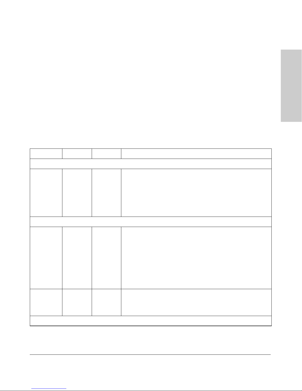
Table 1-2. Switch LEDs
Switch LEDs State Meaning
Power
(green)
Fault
(orange)
On
Off
Off The normal state; indicates there are no fault conditions on the switch.
Flashing
The switch is receiving power.
The switch is NOT receiving power.
1
A fault has occurred on the switch, one of the switch ports, module in the rear of
the switch, or the fan. The Status LED for the component with the fault will flash
simultaneously.
On On briefly after the switch is powered on or reset, at the beginning of switch self
1-6
test. If this LED is on for a prolonged time, the switch has encountered a fatal
hardware failure, or has failed its self test. See chapter 4, “Troubleshooting” for
more information.

Introducing the Switch
Switch LEDs State Meaning
Introducing the Switch
Front of the Switch
Locator (Blue) On
Flashing
Off
Te st
Off The normal operational state; the switch is not undergoing self test.
(green/orange)
On green The switch self test and initialization are in progress after the switch has been
Flashing
orange
Port LEDs
Link Indicates the port LEDs are displaying link information:
(green/orange –
Link and Mode)
Mode The operation of the Mode LED is controlled by the LED Mode select button, and
The Locator LED is used to locate a specific chassis in a area full of chassis. The
LED can be set to be on solid or flash for a specified number of minutes (1-1440).
The default is 30 minutes. Use the command “chassislocate”.
power cycled or reset. The switch is not operational until this LED goes off. The Self
Test LED also comes on briefly when you “hot swap” a mini-GBIC into the switch;
the mini-GBIC is self tested when it is hot swapped.
A component of the switch has failed its self test. The status LED for that component,
1
for example an RJ-45 port, and the switch Fault LED will flash simultaneously.
• if the port LED is on, the port is enabled and receiving a link indication from the
connected device.
• if the port LED is off, the port has no active network cable connected, or is not
receiving lin k beat or sufficient lig ht. Otherwise, the port may have been disabled
through the switch console, the web browser interface, or ProCurve Manager.
if the port LED is Flashing1 (orange) simultaneously with the Fault LED, the
corresponding port has failed its self test.
the current setting is indicated by the LED Mode indicator LEDs near the button.
Press the button to step from one view mode to the next. The default view is Activity
(Act).
LED Mode View
Act Indicates the port LEDs are displaying network activity information.
(green LEDs)
FDx Indicates port LEDs are lit for ports in Full Duplex Mode. Off indicates ½ duplex.
Spd Indicates the port LEDs are displaying the connection speed at which each port is
operating:
• if the port LED is off, the port is operating at 10 Mbps.
• if the port LED is Flashing**, the port is operating at 100 Mbps.
• if the port LED is on continuously, the port is operating at 1000 Mbps.
PoE • If the Mode LED is on the port is providing PoE power.
• If the Mode LED is off the port is not providing PoE power.
• If the Link LED is on the port is enabled for PoE.
• If the Link LED is off the port is disabled for PoE.
• If the Link LED is Flashing, the port has an error or the port is denied power due
to insufficient power.
Usr Reserved for future development
Mdl (Module
Status, green)
On
Flashing
Off
Expansion module is plugged into expansion slot and operating correctly
Expansion module is plugged into expansion slot but has experienced a fault
Expansion module is not plugged into expansion slot
1-7

Introducing the Switch
Introducing the Switch
Front of the Switch
Switch LEDs State Meaning
RPS Status
(green)
EPS Status
(green)
On
Flashing
Off
On
Flashing
Off
Normal operation. RPS is connected and operating correctly. RPS could be
powering the unit.
RPS is connected but has experienced a fault.
RPS is not connected or is not powered on.
Connected to an External Power Supply, and receiving power.
The External Power Supply is connected but has experienced a fault or is
unplugged.
The switch is not connected to an EPS.
Fan Status
(green)
On
Flashing
Normal operation, all fans are ok.
1
One of the unit’s fans has failed. The switch Fault LED will be flashing
simultaneously.
PoE Status On
Off
Flashing
Flashing
Te mp
Off Switch temperature is normal.
(green/Orange)
Flashing
Auxiliary (green/
orange) For more
Flashing
green
1
If any ports are supplying PoE power.
If no ports are supplying PoE power. Should be off only during the boot process.
1
If any port has a internal hardware failure
2
If any port is denied PoE power or detecting an external PD fault
1
An over temperature condition has been detected.
Indicates the switch is processing a USB command file.
information see
the Management
and Configuration
Guide for your
switch.
On green The switch has finished processing the USB command file successfully.
Flashing
orange
Indicates an error condition.
2
Off Indicates that no USB device has been inserted, or that the inserted USB device
cannot be recognized, or that no command file can be found on the inserted USB
device.
1
The flashing behavior is an on/off cycle once every 1.6 seconds, approximately.
2
The flashing behavior is an on/off cycle once every 0.8 seconds, approximately.
LED Mode Select Button and Indicator LEDs
The operation of the Mode LED is controlled by the LED Mode select button,
and the current setting is indicated by the LED Mode indicator LEDs near the
button. Press the button to step from one view mode to the next.
1-8

Introducing the Switch
Figure 1-5. HP ProCurve 2910al-48G Switch
Power
Fault
Locator
Console
LED
Mode
Clear
Reset
10/100/1000Base-T Ports (1 - 48T) Ports are Auto-MDIX
Test
Tmp
Status
Fan
*
Spd mode: off=10 Mbps, 2 flash=100 Mbps, on=1 Gbps, 3 flash=10 Gbps
FDx
Spd
Act
*
12
10
8
6
4
2
11
9
7
5
3
1
Link
Mode
Link
Mode
Status of the Back
Mdl RPS
ProCurve Switch
2910bl-48G
J9147A
24
22
20
18
16
14
2321
1917
1513
Link
Mode
Link
Mode
30
28
26
29
2725
Link
Mode
Link
Mode
Usr
Port LEDs Link
and Mode
Expansion Module LED
LED Mode select button
and indicator LEDs
Power
Fault
Locator
Console
LED
Mode
Clear
Reset
PoE+ Integrated 10/100/1000Base-T Ports (1 - 48T) Ports are Auto-MDIX
Test
Tmp
Status
PoE
Fan
*
Spd mode: off=10 Mbps, 2 flash=100 Mbps, on=1 Gbps, 3 flash=10 Gbps
FDx
Spd
PoE
Act
*
12
10
8
6
4
2
11
9
7
5
3
1
Link
Mode
Link
Mode
Status of the Back
Mdl
RPS
EPS
ProCurve Switch
2910bl-48G-PoE
J9148A
24
2220
18
16
14
2321
1917
1513
Link
Mode
Link
Mode
30
28
26
29
2725
Link
Mode
Link
Mode
Usr
PoE+
LED Mode select button
and indicator LEDs
Port LEDs Link
and Mode
Expansion Module LEDs
Introducing the Switch
Front of the Switch
Figure 1-6. HP ProCurve 2910al-48G-PoE+ Switch
■ The PoE+ switches have an additional mode, PoE. In PoE mode, the Link
LED indicates the PoE configuration for the port:
• On if PoE is enabled on the port
• Off if PoE is disabled on the port.
■ Each port has a Link LED. If it is lit, the port has a link. If the Link LED is
Flashing, the port has failed its self test. The Fault and Self Test LEDs will
be Flashing simultaneously.
■ If the Activity (Act) indicator LED is lit, each port LED displays activity
information for the associated port—it flickers as network traffic is
received and transmitted through the port.
■ If the Full Duplex (FDx) indicator LED is lit, the port LEDs light for those
ports that are operating in full duplex.
■ If the Speed (Spd) indicator LED is lit, the port LEDs behave as follows
to indicate the connection speed for the port:
• Off = 10 Mbps
• Flashing = 100 Mbps (the Flashing behavior is a repeated on/off cycle
once every 0.8 sec.)
• On = 1000 Mbps
1-9

Introducing the Switch
Introducing the Switch
Front of the Switch
■ The Usr Mode LED is reserved for future development
■ If the PoE indicator LED is lit, the Link and Mode LEDs indicate PoE
status:
Link LED:
• On = PoE is enabled on this port
• Off = PoE is disabled on this port.
• Slow Flashing = Internal PoE fault on this port. or has been denied
power
• Fast Flashing = This port is denied PoE power or has an external load
fault.
Mode LED:
• On = PoE power is be supplied on this port
• Off = PoE is not being supplied on this port.
Reset Button
This button is for:
■ Resetting the switch - When the switch is powered on. This action clears
any temporary error conditions that may have occurred and executes the
switch self test.
■ Restoring Factory Default Configuration - When pressed with the
Clear button in a specific pattern, any configuration changes you may have
made through the switch console, the web browser interface, and SNMP
management are removed, and the factory default configuration is
restored to the switch. For the specific method to restore the factory
default configuration, see “Restoring the Factory Default Configuration”
on page 11, “Troubleshooting” of this manual.
Clear Button
This button is used for:
■ Deleting Passwords - When pressed by itself for at least one second, the
button deletes any switch console access passwords that you may have
configured. Use this feature if you have misplaced the password and need
console access. This button is provided as a convenience, however if you
are concerned with the security of the switch configuration and operation,
you should make sure the switch is installed in a secure location. This
button can be disabled by a CLI command.
■ Restoring Factory Default Configuration - See Reset Button above.
1-10
Introducing the Switch
Console Port
This port is used to connect a console to the switch by using the RJ-45 to DB9
cable, supplied with the switch. This connection is described under “Connect
a Console to the Switch” in chapter 2, “Installing the Switch.” The console can
be a PC or workstation running a VT-100 terminal emulator, or a VT-100
terminal.
Expansion Module LEDs
“Expansion Module” LEDs refer to the LEDs specific to the expansion module.
These LEDs are located on the physical expansion module bulkhead. These
LEDs are only viewable in the rear of the Switch 2910al-48G product on the
Expansion Slot Module itself.
Table 1-3. Expansion Module LEDs
Name Color Mode Description
Expansion Module LEDs per module
Introducing the Switch
Front of the Switch
Module
Status
Expansion Module LEDs per port
Link Green/
Mode Green On The operation of the Mode LED is controlled by the LED Mode select
1
The flashing behavior is an on/off cycle once every 1.6 seconds, approximately.
Green/
Orange
Orange
On green
Off
Flashing
orange
On green
Off
Flashing
orange
Expansion module is plugged into expansion slot and operating correctly
Expansion module's power has been turned OFF, and the card can be
removed from the box if necessary.
Expansion module is plugged into expansion slot but has experienced a
fault. Flashes simultaneously with the Fault LED.
Indicates that the port LEDs are displaying link information:
• if the port LED is on, the port is enabled and receiving a link indication
from the connected device.
• if the port LED is off, the port has no active network cable connected,
or is not receiving link beat or sufficient light. Otherwise, the port may
have been disabled through the switch console, the web browser
interface, or ProCurve Manager.
• if the port LED is flashing
corresponding port has experienced a hardware failure or has failed
its self test.
button, and the current setting is indicated by the LED Mode indicator
LEDs near the button. Press the button to step from one view mode to the
next. The default view is Activity (Act). See page 7.
1
simultaneously with the Fault LED, the
Expansion module LEDs operate in modes for Link and Mode. FDx and Spd modes
have no meaning for the 10-GbE ports on the expansion module.
1-11
Introducing the Switch
Introducing the Switch
System MAC Address
00-01-E7-12-34-56
Serial No. SG12345678
Line: 50/60 Hz.
100-127 V~ 10 A
200-240 V~ 5 A
12V System Power (RPS) Input
CAUTION: MULTIPLE POWER SOURCES
Disconnect AC power cord and RPS cable,
to completely remove power from the unit.
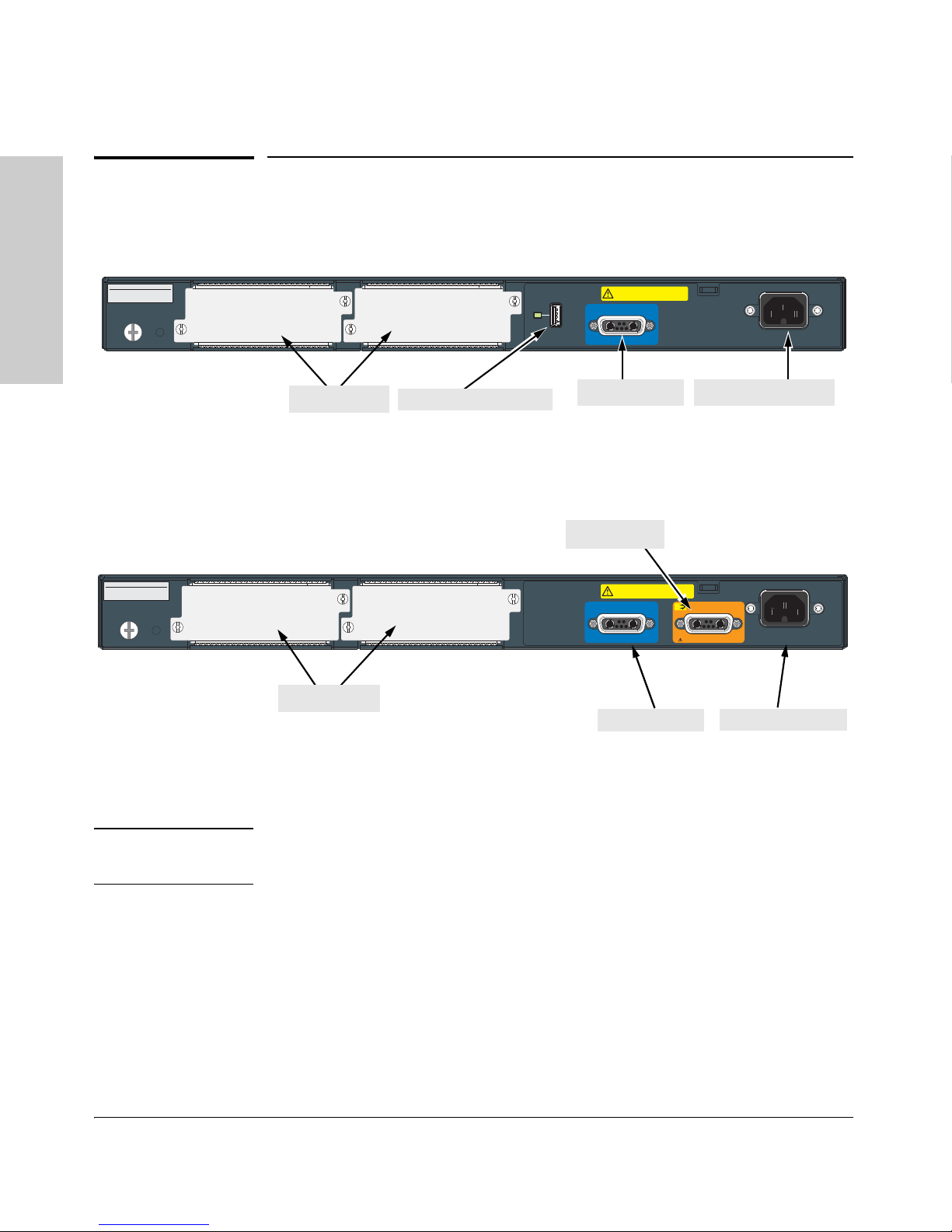
Slot
B
Slot
A
Auxiliary Port
AC power connector
al module slots
RPS Input Port
Auxiliary Port and LED
PoE
+
System MAC Address
00-01-E7-12-34-56
Serial No. SG12345678
Line: 50/60 Hz.
100-127 V~ 10 A
200-240 V~ 5 A
12V System Power (RPS) Input
50V PoE (EPS) Input
CAUTION: MULTIPLE POWER SOURCES
Disconnect AC power cord, and EPS and RPS
cables, to completely remove power from the unit.
Connect ProCurve 620 EPS only
Slot
B
Slot
A
AC power connector
RPS Input Port
al module slot
EPS Input Port
Back of the Switch
Back of the Switch
Figure 1-7. HP ProCurve 2910al-48G Switch
Figure 1-8. HP ProCurve 2910al-24G-PoE+ Switch
al Module Slots
Caution It is required for the switch to be powered down before inserting or extracting
the Expansion Module.
These switches support three al modules. The al modules provide different
types of connectivity options for the switch.
■ The J9149A – provides two 10-GbE CX4 fixed copper ports
■ The J9008A – provides two 10-GbE SFP+ slots that support a number of
different transceivers. For supported transceivers see Table 1-1 on page
1-2.
■ The J9165A – these modules have 1 fixed short-range CX4 port (up to 3
meters), and comes in a kit of 2 modules with one 0.5 meter cable.
Primarily used to interconnect two switches at 10-GbE speed.
1-12

Introducing the Switch
Introducing the Switch
Back of the Switch
RPS and EPS Input Ports
The 2910al Switches support connectivity to a redundant power supply (RPS/
EPS). The HP ProCurve 620 Redundant and External Power Supply (J8696A)
and the HP ProCurve 630 Redundant and/or External Power Supply (J9443A)
are accessory products for these switches.
The RPS functionality of the HP ProCurve 620 RPS/EPS and the HP ProCurve
630 RPS/EPS provide redundant system power in case the switch’s internal
power supply fails.
The EPS functionality of the HP ProCurve 620 RPS/EPS is not supported on
the 2910al switches, however, the HP ProCurve 630 RPS/EPS provides redundant or additional PoE+ power to the 2910al PoE+ switches.
Power Connector
The 2910al Switches do not have a power switch; they are powered on when
connected to an active AC power source. These switches automatically adjust
to any voltage between 100--127 and 200--240 volts and either 50 or 60 Hz.
There are no voltage range settings required.
1-13
Introducing the Switch
Introducing the Switch
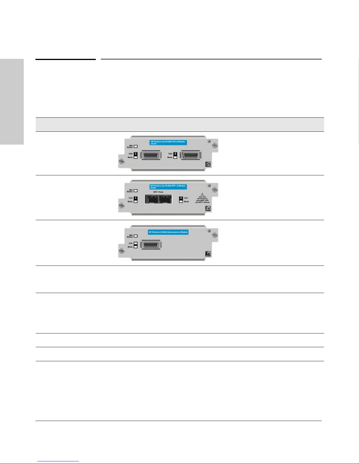
HP ProCurve Switch al Modules
HP ProCurve Switch al Modules
The HP ProCurve al Modules are components you can add to a HP ProCurve
al switch to provide a variety of network connectivity options. The following
modules is available as of this printing:
Module Description
HP ProCurve 10-GbE
CX4 al Module
(J9149A)
1,3
HP ProCurve 2-Port
10-GbE SFP+ al Module
(J9008A)
2,3
HP ProCurve 10-GbE al
Interconnect Kit
(J9165A)
3
2-port 10 Gigabit switch expansion
module. This module has two fixed
CX4 ports.
1
2-port 10 Gigabit switch expansion
module. This module has two SFP+
2
ports.
Two, 1-port 10 Gigabit switch
expansion modules. These
modules have 1 fixed CX4 port.
These modules come in a kit of 2
modules with one 0.5 meter cable.
1
Supported accessories: As of this printing the following HP ProCurve accessories are supported by the HP ProCurve
Switch 2-Port 10-GbE CX4 al Module:
• ProCurve 10-GbE CX4 Media Converter (J8439A).
2
Supported transceivers: As of this printing the following HP ProCurve transceivers are supported by the HP ProCurve
Switch al 10-GbE 2-port SFP+ Module:
• HP ProCurve SFP+ SR transceiver (J9150A)
• HP ProCurve SFP+ LR transceiver (J9151A)
• HP ProCurve SFP+ LRM transceiver (J9152A)
4
3
These modules require switch software version W.14.01 or later to be installed in the switch.
4
The J8439A Media Converter is not supported on the Interconnect kit.
Contact your HP ProCurve authorized networking products reseller or your
HP ProCurve representative for information on availability of other modules
and transceivers. You can also visit the HP ProCurve networking products
Website www.hp.com/go/procurve to get more information.
1-14
Introducing the Switch
Features
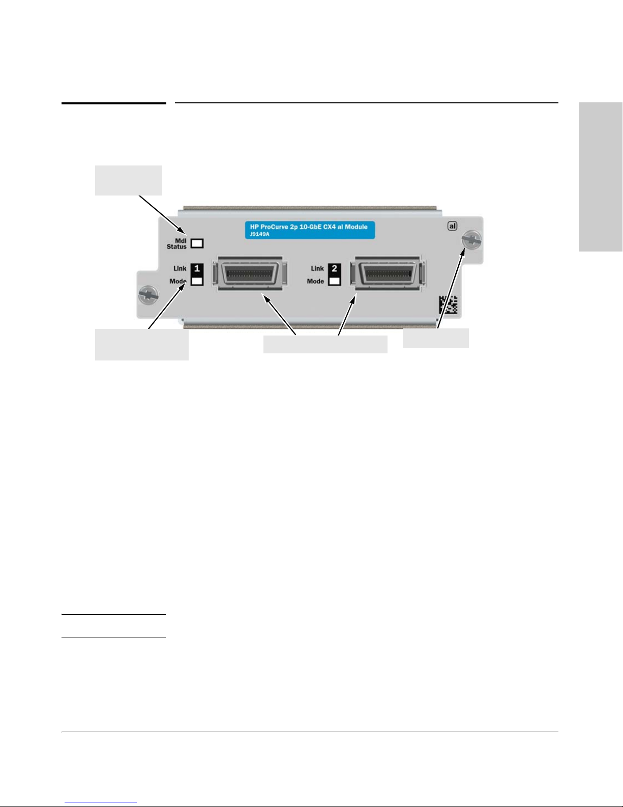
HP ProCurve 10-GbE CX4 al Module
Module Status
LEDs
Retaining screw
Copper CX4 port connections
Link and Mode LEDs
(one pair per port)
Introducing the Switch
Features
Figure 2. Front of the al 10-GbE CX4 Module
The al Modules have the following features:
■ Connectivity ports.
■ LEDs that provide information for each port on the link and mode status.
■ LED that provides information on module status.
■ “hot swap transceiver” support—you can add, replace, or change the type
of any of the transceivers that you use in the SFP+ module ports, without
having to first remove the module, and without having to shut down the
switch.
Standards adherence:
■ IEEE 802.3ak CX4
■ IEEE 802.3ae XAUI
Note The al modules are not “Hot-swappable”.
1-15

Introducing the Switch
Introducing the Switch
Switch Features
Switch Features
The features of the 2910al Switch include:
■ 24 or 48 auto-sensing 10/100/1000Base-T RJ-45 ports with Auto-MDIX.
■ Four dual-personality ports—either the auto sensing 10/100/1000Base-T
RJ-45 or the mini-GBIC can be used for each port.
■ Two slots (optional al module slot) are provided in the back of the device
to support a series of transceivers to provide connectivity to other switch
boxes, to a 10 Gigabit concentrator or to any Ethernet compatible uplink.
■ An auxiliary (USB) port for processing a USB command file.
■ The Switches can be connected to a ProCurve RPS/EPS and receive
redundant power from that unit. If the internal power supply in the switch
fails, the RPS/EPS unit will immediately provide all the power necessary
to keep the switch running.
■ Plug-and-play networking—all ports are enabled—just connect the
network cables to active network devices and your switched network is
operational.
■ IEEE 802.3ab Auto MDIX on all 10/100/1000 twisted-pair ports, meaning
that all connections can be made using straight-through twistedpair cables. Cross-over cables are not required, although they will also
work. The pin operation of each port is automatically adjusted for the
attached device: if the switch detects that another switch or hub is
connected to the port, it configures the port as MDI; if the switch detects
that an end-node device is connected to the port, it configures the port as
MDI-X. If both devices use Auto-MDIX, the configuration is randomly
selected.
■ Automatic learning of the network addresses in each switch’s 2048-
address forwarding table, (with configurable address aging value).
■ Automatically negotiated full-duplex operation for the 10/100/1000 RJ-45
ports when connected to other auto-negotiating devices—the mini-GBIC
ports always operate at full duplex.
■ Easy management of the switch through several available interfaces:
• console interface—a full featured, easy to use, VT-100 terminal
interface that is especially good for out-of-band switch management
or for Telnet access to the switch.
• web browser interface—an easy to use built-in graphical interface
that can be accessed from common web browsers.
1-16

Introducing the Switch
Introducing the Switch
Switch Features
• ProCurve Manager—an SNMP-based, graphical network management tool that you can use to manage your entire network. This
product is included with your new switch.
■ Support for the Spanning Tree Protocol to eliminate network loops
■ Support for up to 256 IEEE 802.1Q-compliant VLANs so you can divide
the attached end nodes into logical groupings that fit your business needs.
■ Support for many advanced features to enhance network performance—
for a description, see the Management and Configuration Guide, which
is on the ProCurve Web site www.hp.com/go/procurve/manuals.
■ Download of new switch software for product enhancements or bug fixes.
■ Support for IEEE 802.3af and 802.3at standard and Pre-standard PoE and
PoE+ devices.
■ Support for SFP+ transceivers at 10-GbE speed.
1-17


Installing the Switch
2
Installing the Switch
The HP ProCurve 2910al Switches come with an accessory kit that includes
the brackets for mounting the switch in a standard 19-inch telco rack, in an
equipment cabinet, and with rubber feet that can be attached so the switch
can be securely located on a horizontal surface. The brackets are designed to
allow mounting the switch in a variety of locations and orientations. For other
mounting options contact your local ProCurve authorized network reseller or
ProCurve representative. This chapter shows how to install the switch.
Caution If the switch is to be shipped in a rack, be sure to use only an HP 10K rack.
Mount the switch using rail kit, ProCurve 1U RK MT SWITCH 10K ALL, part
number 356578-B21 and shelf kit AB469A, HP rx 16/26 Factory Rackmount
Shelf Kit. Both kits must be used. Otherwise you will void the warranty.
Included Parts
The 2910al Switches have the following components shipped with them:
■ HP ProCurve Switch Quick Setup guide
■ HP ProCurve Switches General Safety and Regulatory Information
booklet
■ 2910al Switch Specific Safety and Regulatory Information sheet
■ Read Me First
■ Customer Support/Warranty booklet
■ Console cable (5188-3836)
2-1

Installing the Switch
Installing the Switch
Included Parts
■ Accessory kit
(5069-5705)
two mounting brackets
eight 8-mm M4 screws to attach the
mounting brackets to the switch
four 5/8-inch number 12-24 screws to
attach the switch to a rack
four rubber feet
■ Power cord, one of the following:
Non-PoE Switches PoE+ Switches
Australia/New Zealand
China
Continental Europe
Denmark
Japan
Switzerland
United Kingdom/Hong Kong/Singapore
South Africa and India
Thailand and Brazil
Ta iw a n
Israel
United States/Canada/Mexico
Japan Power
Cord Warning
8121-0828
8121-0829
8120-0823
8120-0826
8120-4753
8120-0827
8120-0824
8120-0919
8121-0673
8121-0965
8121-1035
8121-0822
Australia/New Zealand
China
Continental Europe
Denmark
Japan
Switzerland
United Kingdom/Hong Kong/Singapore
South Africa and India
Thailand and Brazil
Taiw an
Israel
United States/Canada/Mexico
8121-0857
8121-1034
8120-5336
8120-5340
8120-5342
8120-5339
8120-5334
8120-5341
8121-0671
8121-0967
8121-1009
8121-0973
2-2

Installing the Switch
Installing the Switch
Included Parts
Installation Precautions:
Follow these precautions when installing the 2910al Switches.
WARNING ■ The rack or cabinet should be adequately secured to prevent it
from becoming unstable and/or falling over.
■ Devices installed in a rack or cabinet should be mounted as low as
possible, with the heaviest devices at the bottom and progressively
lighter devices installed above.
■ Do not wall mount any of the 2910al Switches.
Cautions ■ If the switch is to be shipped in a rack, be sure to use only an HP 10K rack.
Mount the switch using rail kit part number 356578-B21 and shelf kit
AB469A. Both kits must be used. Otherwise you will void the warranty.
■ Ensure the power source circuits are properly grounded, then use the
power cord supplied with the switch to connect it to the power source.
■ If your installation requires a different power cord than the one supplied
with the switch and power supply, be sure the cord is adequately sized for
the switch’s current requirements. In addition, be sure to use a power cord
displaying the mark of the safety agency that defines the regulations for
power cords in your country. The mark is your assurance that the power
cord can be used safely with the switch and power supply.
■ When installing the switch, the AC outlet should be near the switch and
should be easily accessible in case the switch must be powered off.
■ Ensure the switch does not overload the power circuits, wiring, and over-
current protection. To determine the possibility of overloading the supply
circuits, add together the ampere ratings of all devices installed on the
same circuit as the switch and compare the total with the rating limit for
the circuit. The maximum ampere ratings are usually printed on the
devices near the AC power connectors.
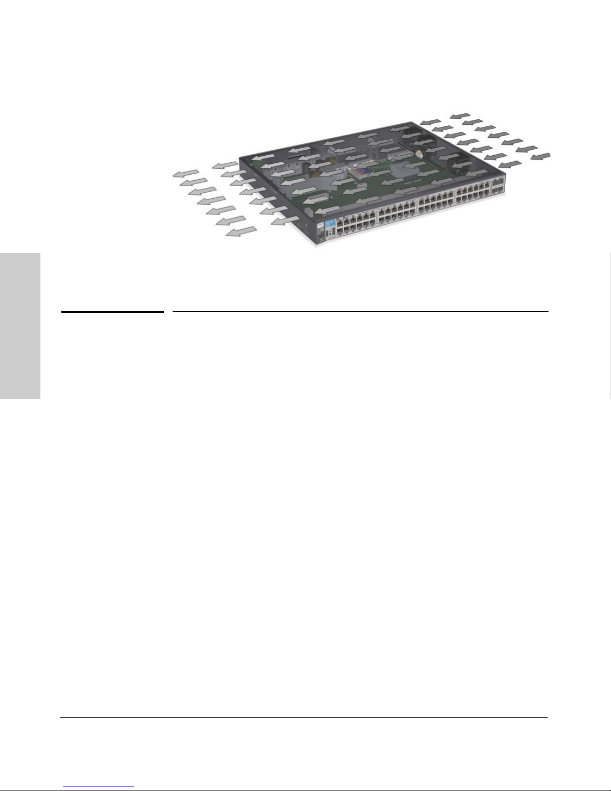
■ Do not install the switch in an environment where the operating ambient
temperature might exceed 55C (131F)
■ Ensure the air flow around the sides of the switch is not restricted. Leave
1
.
at least 7.6 cm (3 inches) for cooling. See Figure 2-1 for the air flow
direction.
2-3
Installing the Switch
Installing the Switch
Installation Procedures
Figure 2-1. Air flow direction of the 2910al switch
Installation Procedures
Summary
1. Prepare the installation site (page 2-5). Ensure the physical environment is properly prepared, including having the correct network cabling
ready to connect to the switch and having an appropriate location for the
switch. See page 2-3 for some installation precautions.
2. Verify the switch passes self test (page 2-5). Plug the switch into a
power source and observe that the LEDs on the switch’s front panel
indicate correct switch operation. When self test is complete, unplug the
switch.
3. (Optional) Install a module (page 2-8).
4. Mount the switch (page 2-11). The Switch can be mounted in a 19-inch
telco rack, in an equipment cabinet, or on a horizontal surface.
5. (Optional) Install a transceiver (page 2-14). If you have installed a
module, you can now install one or two transceivers.
6. (Optional) Install mini-GBICs and SFPs (page 2-16). The switch has
four slots for installing mini-GBICs. Depending on where you will mount
the switch, it may be easier to install the mini-GBICs first. Mini-GBICs can
be installed or removed while the switch is powered on.
7. Connect power to the switch (page 2-18). Once the switch is mounted,
plug it into the nearby main power source.
2-4
 Loading...