

Page 1
management and
configuration guide
hp procurve series 2500 switches
www.hp.com/go/procurve
Page 2

Page 3

HP ProCurve Switches
2512 and 2524
Management and Configuration Guide
Software Release F.01or Greater
Page 4

© Copyright 2000 Hewlett-Packard Company
All Rights Reserved.
This document contains information which is protected by
copyright. Reproduction, adaptation, or translation without
prior permission is prohibited, except as allowed under the
copyright laws.
Publication Number
5969-2354
August 2000
Applicable Product
HP ProCurve Switch 2512 (J4812A)
HP ProCurve Switch 2524 (J4813A)
Trademark Credits
Microsoft, Windows, Windows 95, and Microsoft Windows
NT are registered trademarks of Microsoft Corporation.
Internet Explorer is a trademark of Microsoft Corporation.
Ethernet is a registered trademark of Xerox Corporation.
Netscape is a registered trademark of Netscape Corporation.
Disclaimer
The information contained in this document is subject to
change without notice.
HEWLETT-PACKARD COMPANY MAKES NO WARRANTY
OF ANY KIND WITH REGARD TO THIS MATERIAL,
INCLUDING, BUT NOT LIMITED TO, THE IMPLIED
WARRANTIES OF MERCHANTABILITY AND FITNESS
FOR A PARTICULAR PURPOSE. Hewlett-Packard shall not
be liable for errors contained herein or for incidental or
consequential damages in connection with the furnishing,
performance, or use of this material.
Hewlett-Packard assumes no responsibility for the use or
reliability of its software on equipment that is not furnished
by Hewlett-Packard.
Warranty
See the Customer Support/Warranty booklet included with
the product.
A copy of the specific warranty terms applicable to your
Hewlett-Packard products and replacement parts can be
obtained from your HP Sales and Service Office or
authorized dealer.
Hewlett-Packard Company
8000 Foothills Boulevard, m/s 5551
Roseville, California 95747-5551
http://www.hp.com/go/procurve
Page 5

Preface
Preface
Use of This Guide and Other ProCurve Switch
Documentation
This guide describes how to use the command line interface (CLI), menu
interface, and web browser interface for the HP ProCurve Switches 2512 and
2524 - hereafter referred to individually as the “Switch 2512” or “Switch 2524”
and collectively as the “Switches 2512/2524” or “Series 2500 switches”).
■ If you need information on specific parameters in the menu interface,
refer to the online help provided in the interface.
■ If you need information on a specific command in the CLI, type the
command name followed by “help” (<command> help).
■ If you need information on specific features in the HP Web Browser
Interface (hereafter referred to as the “web browser interface”), use the
online help available for the web browser interface. For more information
on web browser Help options, refer to “Online Help for the HP Web
Browser Interface” on page 4-12.
■ If you need further information on Hewlett-Packard switch technology,
refer to HP’s ProCurve Networking website at:
http://www.hp.com/go/procurve
iii
Page 6

Page 7

Contents
Contents
Preface . . . . . . . . . . . . . . . . . . . . . . . . . . . . . . . . . . . . . . . . . . . . . . . . . . . . . . . . iii
Use of This Guide and Other ProCurve Switch Documentation . . . . . . iii
1: Selecting a Management Interface
Chapter Contents . . . . . . . . . . . . . . . . . . . . . . . . . . . . . . . . . . . . . . . . . . . . . 1-1
Overview . . . . . . . . . . . . . . . . . . . . . . . . . . . . . . . . . . . . . . . . . . . . . . . . . . . . . 1-2
Understanding Management Interfaces . . . . . . . . . . . . . . . . . . . . . . . . . 1-2
Advantages of Using the Menu Interface . . . . . . . . . . . . . . . . . . . . . . . . 1-3
Advantages of Using the CLI . . . . . . . . . . . . . . . . . . . . . . . . . . . . . . . . . . . 1-4
CLI Usage . . . . . . . . . . . . . . . . . . . . . . . . . . . . . . . . . . . . . . . . . . . . . . 1-4
Advantages of Using the HP Web Browser Interface . . . . . . . . . . . . . 1-5
Advantages of Using HP TopTools for Hubs & Switches . . . . . . . . . 1-6
2. Using the Menu Interface
Chapter Contents . . . . . . . . . . . . . . . . . . . . . . . . . . . . . . . . . . . . . . . . . . . . . 2-1
Overview . . . . . . . . . . . . . . . . . . . . . . . . . . . . . . . . . . . . . . . . . . . . . . . . . . . . . 2-2
Starting and Ending a Menu Session . . . . . . . . . . . . . . . . . . . . . . . . . . . 2-3
How To Start a Menu Interface Session . . . . . . . . . . . . . . . . . . . . . . . . . 2-4
How To End a Menu Session and Exit from the Console: . . . . . . . . . . 2-5
Main Menu Features . . . . . . . . . . . . . . . . . . . . . . . . . . . . . . . . . . . . . . . . . . 2-7
Screen Structure and Navigation . . . . . . . . . . . . . . . . . . . . . . . . . . . . . . . 2-9
Rebooting the Switch . . . . . . . . . . . . . . . . . . . . . . . . . . . . . . . . . . . . . . . . . 2-12
Menu Features List . . . . . . . . . . . . . . . . . . . . . . . . . . . . . . . . . . . . . . . . . . . 2-14
Where To Go From Here . . . . . . . . . . . . . . . . . . . . . . . . . . . . . . . . . . . . . . 2-15
3. Using the Command Line Interface (CLI)
Chapter Contents . . . . . . . . . . . . . . . . . . . . . . . . . . . . . . . . . . . . . . . . . . . . . 3-1
Overview . . . . . . . . . . . . . . . . . . . . . . . . . . . . . . . . . . . . . . . . . . . . . . . . . . . . . 3-2
v
Page 8

Contents
Accessing the CLI . . . . . . . . . . . . . . . . . . . . . . . . . . . . . . . . . . . . . . . . . . . . . 3-2
Using the CLI . . . . . . . . . . . . . . . . . . . . . . . . . . . . . . . . . . . . . . . . . . . . . . . . . 3-2
Privilege Levels at Logon . . . . . . . . . . . . . . . . . . . . . . . . . . . . . . . . . . . . . 3-3
Privilege Level Operation . . . . . . . . . . . . . . . . . . . . . . . . . . . . . . . . . . . . . 3-4
Operator Privileges . . . . . . . . . . . . . . . . . . . . . . . . . . . . . . . . . . . . . . 3-4
Manager Privileges . . . . . . . . . . . . . . . . . . . . . . . . . . . . . . . . . . . . . . . 3-5
How To Move Between Levels . . . . . . . . . . . . . . . . . . . . . . . . . . . . . . . . 3-7
Listing Commands and Command Options . . . . . . . . . . . . . . . . . . . . . . 3-8
Listing Commands Available at Any Privilege Level . . . . . . . . . . . 3-8
Command Option Displays . . . . . . . . . . . . . . . . . . . . . . . . . . . . . . . 3-10
Displaying CLI "Help" . . . . . . . . . . . . . . . . . . . . . . . . . . . . . . . . . . . . . . . 3-11
Configuration Commands and the Context Configuration Modes . . 3-13
CLI Control and Editing . . . . . . . . . . . . . . . . . . . . . . . . . . . . . . . . . . . . . . 3-16
4. Using the HP Web Browser Interface
Chapter Contents . . . . . . . . . . . . . . . . . . . . . . . . . . . . . . . . . . . . . . . . . . . . . 4-1
Overview . . . . . . . . . . . . . . . . . . . . . . . . . . . . . . . . . . . . . . . . . . . . . . . . . . . . . 4-2
General Features . . . . . . . . . . . . . . . . . . . . . . . . . . . . . . . . . . . . . . . . . . . . . . 4-3
Web Browser Interface Requirements . . . . . . . . . . . . . . . . . . . . . . . . . . 4-4
Starting an HP Web Browser Interface Session with the Switch . . 4-5
Using a Standalone Web Browser in a PC or UNIX Workstation . . . . 4-5
Using HP TopTools for Hubs & Switches . . . . . . . . . . . . . . . . . . . . . . . 4-6
Tasks for Your First HP Web Browser Interface Session . . . . . . . . . 4-8
Viewing the “First Time Install” Window . . . . . . . . . . . . . . . . . . . . . . . . 4-8
Creating Usernames and Passwords in the Browser Interface . . . . . . 4-9
Using the Passwords . . . . . . . . . . . . . . . . . . . . . . . . . . . . . . . . . . . . 4-11
Using the User Names . . . . . . . . . . . . . . . . . . . . . . . . . . . . . . . . . . . 4-11
If You Lose a Password . . . . . . . . . . . . . . . . . . . . . . . . . . . . . . . . . . 4-11
Online Help for the HP Web Browser Interface . . . . . . . . . . . . . . . . . 4-12
Support/Mgmt URLs Feature . . . . . . . . . . . . . . . . . . . . . . . . . . . . . . . . . . 4-13
Support URL . . . . . . . . . . . . . . . . . . . . . . . . . . . . . . . . . . . . . . . . . . . . . . 4-14
Help and the Management Server URL . . . . . . . . . . . . . . . . . . . . . . . . 4-14
Status Reporting Features . . . . . . . . . . . . . . . . . . . . . . . . . . . . . . . . . . . . 4-16
The Overview Window . . . . . . . . . . . . . . . . . . . . . . . . . . . . . . . . . . . . . . 4-16
vi
Page 9

Contents
The Port Utilization and Status Displays . . . . . . . . . . . . . . . . . . . . . . . 4-17
Port Utilization . . . . . . . . . . . . . . . . . . . . . . . . . . . . . . . . . . . . . . . . . 4-17
Port Status . . . . . . . . . . . . . . . . . . . . . . . . . . . . . . . . . . . . . . . . . . . . . 4-19
The Alert Log . . . . . . . . . . . . . . . . . . . . . . . . . . . . . . . . . . . . . . . . . . . . . . 4-20
Sorting the Alert Log Entries . . . . . . . . . . . . . . . . . . . . . . . . . . . . . 4-20
Alert Types . . . . . . . . . . . . . . . . . . . . . . . . . . . . . . . . . . . . . . . . . . . . 4-21
Viewing Detail Views of Alert Log Entries . . . . . . . . . . . . . . . . . . 4-22
The Status Bar . . . . . . . . . . . . . . . . . . . . . . . . . . . . . . . . . . . . . . . . . . . . . 4-23
Setting Fault Detection Policy . . . . . . . . . . . . . . . . . . . . . . . . . . . . . . . . 4-24
5. Configuring IP Addressing, Interface Access, and
System Information
Chapter Contents . . . . . . . . . . . . . . . . . . . . . . . . . . . . . . . . . . . . . . . . . . . . . 5-1
Overview . . . . . . . . . . . . . . . . . . . . . . . . . . . . . . . . . . . . . . . . . . . . . . . . . . . . . 5-2
IP Configuration . . . . . . . . . . . . . . . . . . . . . . . . . . . . . . . . . . . . . . . . . . . . . . 5-3
Just Want a Quick Start? . . . . . . . . . . . . . . . . . . . . . . . . . . . . . . . . . . . . . 5-4
IP Addressing with Multiple VLANs . . . . . . . . . . . . . . . . . . . . . . . . . . . . 5-4
IP Addressing in a Stacking Environment . . . . . . . . . . . . . . . . . . . . . . . 5-5
Menu: Configuring IP Address, Gateway, Time-To-Live (TTL),
and Timep . . . . . . . . . . . . . . . . . . . . . . . . . . . . . . . . . . . . . . . . . . . . . . . . . . 5-5
CLI: Configuring IP Address, Gateway, Time-To-Live (TTL),
and Timep . . . . . . . . . . . . . . . . . . . . . . . . . . . . . . . . . . . . . . . . . . . . . . . . . . 5-7
Web: Configuring IP Addressing . . . . . . . . . . . . . . . . . . . . . . . . . . . . . . 5-10
How IP Addressing Affects Switch Operation . . . . . . . . . . . . . . . . . . . 5-10
DHCP/Bootp Operation . . . . . . . . . . . . . . . . . . . . . . . . . . . . . . . . . . 5-11
Network Preparations for Configuring DHCP/Bootp . . . . . . . . . 5-14
Globally Assigned IP Network Addresses . . . . . . . . . . . . . . . . . . . . . . 5-15
Interface Access: Console/Serial Link, Web, and Inbound Telnet 5-16
Menu: Modifying the Interface Access . . . . . . . . . . . . . . . . . . . . . . . . . 5-17
CLI: Modifying the Interface Access . . . . . . . . . . . . . . . . . . . . . . . . . . . 5-18
System Information . . . . . . . . . . . . . . . . . . . . . . . . . . . . . . . . . . . . . . . . . . 5-21
Menu: Viewing and Configuring System Information . . . . . . . . . . . . . 5-22
CLI: Viewing and Configuring System Information . . . . . . . . . . . . . . 5-23
Web: Configuring System Parameters . . . . . . . . . . . . . . . . . . . . . . . . . 5-25
vii
Page 10

Contents
6. Optimizing Port Usage Through Traffic Control and
Port Trunking
Chapter Contents . . . . . . . . . . . . . . . . . . . . . . . . . . . . . . . . . . . . . . . . . . . . . 6-1
Overview . . . . . . . . . . . . . . . . . . . . . . . . . . . . . . . . . . . . . . . . . . . . . . . . . . . . . 6-2
Viewing Port Status and Configuring Port Parameters . . . . . . . . . . . 6-2
Menu: Viewing Port Status and Configuring Port Parameters . . . . . . 6-5
CLI: Viewing Port Status and Configuring Port Parameters . . . . . . . . 6-6
Web: Viewing Port Status and Configuring Port Parameters . . . . . . . 6-9
Port Trunking . . . . . . . . . . . . . . . . . . . . . . . . . . . . . . . . . . . . . . . . . . . . . . . . 6-10
Switch 2512 and 2524 Port Trunk Features and Operation . . . . . . . . 6-11
Trunk Configuration Methods . . . . . . . . . . . . . . . . . . . . . . . . . . . . . . . . 6-12
Menu: Viewing and Configuring a Static Trunk Group . . . . . . . . . . . . 6-16
Check the Event Log (page 11-11) to verify that the trunked
ports are operating properly. . . . . . . . . . . . . . . . . . . . . . . . . . . . . . 6-18
CLI: Viewing and Configuring a Static or Dynamic Port Trunk Group . .
6-18
Using the CLI To View Port Trunks . . . . . . . . . . . . . . . . . . . . . . . . 6-18
Using the CLI To Configure a Static or Dynamic Trunk Group . 6-20
Web: Viewing Existing Port Trunk Groups . . . . . . . . . . . . . . . . . . . . . 6-23
Trunk Group Operation Using LACP . . . . . . . . . . . . . . . . . . . . . . . . . . 6-24
Default Port Operation . . . . . . . . . . . . . . . . . . . . . . . . . . . . . . . . . . 6-25
LACP Notes and Restrictions . . . . . . . . . . . . . . . . . . . . . . . . . . . . . 6-26
Trunk Group Operation Using the “Trunk” Option . . . . . . . . . . . . . . . 6-27
Trunk Operation Using the “FEC” Option . . . . . . . . . . . . . . . . . . . . . . 6-27
How the Switch Lists Trunk Data . . . . . . . . . . . . . . . . . . . . . . . . . . . . . 6-28
Outbound Traffic Distribution Across Trunked Links . . . . . . . . . . . . 6-28
7: Using Passwords, Port Security, and Authorized IP
Managers To Protect Against Unauthorized Access
Chapter Contents . . . . . . . . . . . . . . . . . . . . . . . . . . . . . . . . . . . . . . . . . . . . . 7-1
Overview . . . . . . . . . . . . . . . . . . . . . . . . . . . . . . . . . . . . . . . . . . . . . . . . . . . . . 7-3
Using Password Security . . . . . . . . . . . . . . . . . . . . . . . . . . . . . . . . . . . . . . . 7-4
Menu: Setting Manager and Operator passwords . . . . . . . . . . . . . . . . . 7-5
CLI: Setting Manager and Operator Passwords . . . . . . . . . . . . . . . . . . . 7-7
Web: Configuring User Names and Passwords . . . . . . . . . . . . . . . . . . . 7-8
viii
Page 11

Contents
Configuring and Monitoring Port Security . . . . . . . . . . . . . . . . . . . . . . 7-9
Basic Operation . . . . . . . . . . . . . . . . . . . . . . . . . . . . . . . . . . . . . . . . . . . . . 7-9
Blocking Unauthorized Traffic . . . . . . . . . . . . . . . . . . . . . . . . . . . . 7-10
Trunk Group Exclusion . . . . . . . . . . . . . . . . . . . . . . . . . . . . . . . . . . 7-11
Planning Port Security . . . . . . . . . . . . . . . . . . . . . . . . . . . . . . . . . . . . . . 7-11
CLI: Port Security Command Options and Operation . . . . . . . . . . . . 7-13
CLI: Displaying Current Port Security Settings . . . . . . . . . . . . . . 7-16
CLI: Configuring Port Security . . . . . . . . . . . . . . . . . . . . . . . . . . . . 7-17
Web: Displaying and Configuring Port Security Features . . . . . . . . . 7-21
Reading Intrusion Alerts and Resetting Alert Flags . . . . . . . . . . . . . . 7-22
Notice of Security Violations . . . . . . . . . . . . . . . . . . . . . . . . . . . . . 7-22
How the Intrusion Log Operates . . . . . . . . . . . . . . . . . . . . . . . . . . 7-22
Keeping the Intrusion Log Current by Resetting Alert Flags . . . 7-23
Menu: Checking for Intrusions, Listing Intrusion Alerts, and
Resetting Alert Flags . . . . . . . . . . . . . . . . . . . . . . . . . . . . . . . . . . . . 7-24
CLI: Checking for Intrusions, Listing Intrusion Alerts, and Resetting
Alert Flags . . . . . . . . . . . . . . . . . . . . . . . . . . . . . . . . . . . . . . . . . . . . . 7-25
Using the Event Log To Find Intrusion Alerts . . . . . . . . . . . . . . . 7-27
Web: Checking for Intrusions, Listing Intrusion Alerts,
and Resetting Alert Flags . . . . . . . . . . . . . . . . . . . . . . . . . . . . . . . . 7-28
Operating Notes for Port Security . . . . . . . . . . . . . . . . . . . . . . . . . . . . . 7-28
Using IP Authorized Managers . . . . . . . . . . . . . . . . . . . . . . . . . . . . . . . 7-30
Access Levels . . . . . . . . . . . . . . . . . . . . . . . . . . . . . . . . . . . . . . . . . . . . . . 7-31
Defining Authorized Management Stations . . . . . . . . . . . . . . . . . . . . . 7-31
Overview of IP Mask Operation . . . . . . . . . . . . . . . . . . . . . . . . . . . 7-32
Menu: Viewing and Configuring IP Authorized Managers . . . . . . . . . 7-33
CLI: Viewing and Configuring Authorized IP Managers . . . . . . . . . . . 7-34
Listing the Switch’s Current Authorized IP Manager(s) . . . . . . . 7-34
Configuring IP Authorized Managers for the Switch . . . . . . . . . . 7-35
Web: Configuring IP Authorized Managers . . . . . . . . . . . . . . . . . . . . . 7-36
Building IP Masks . . . . . . . . . . . . . . . . . . . . . . . . . . . . . . . . . . . . . . . . . . 7-36
Configuring One Station Per Authorized Manager IP Entry . . . . 7-36
Configuring Multiple Stations Per Authorized Manager IP Entry 7-37
Additional Examples for Authorizing Multiple Stations . . . . . . . 7-39
Operating and Troubleshooting Notes . . . . . . . . . . . . . . . . . . . . . . . . . 7-39
8: Configuring for Network Management Applications
Chapter Contents . . . . . . . . . . . . . . . . . . . . . . . . . . . . . . . . . . . . . . . . . . . . . 8-1
Overview . . . . . . . . . . . . . . . . . . . . . . . . . . . . . . . . . . . . . . . . . . . . . . . . . . . . . 8-2
ix
Page 12

Contents
SNMP Management Features . . . . . . . . . . . . . . . . . . . . . . . . . . . . . . . . . . 8-3
Configuring for SNMP Access to the Switch . . . . . . . . . . . . . . . . . . . . 8-4
SNMP Communities . . . . . . . . . . . . . . . . . . . . . . . . . . . . . . . . . . . . . . . . . . . 8-6
Menu: Viewing and Configuring SNMP Communities . . . . . . . . . . . . . 8-6
To View, Edit, or Add SNMP Communities: . . . . . . . . . . . . . . . . . . 8-6
CLI: Viewing and Configuring Community Names . . . . . . . . . . . . . . . . 8-8
Listing Current Community Names and Values . . . . . . . . . . . . . . . 8-8
Configuring Identity Information . . . . . . . . . . . . . . . . . . . . . . . . . . . 8-9
Configuring Community Names and Values . . . . . . . . . . . . . . . . . . 8-9
Trap Receivers and Authentication Traps . . . . . . . . . . . . . . . . . . . . . 8-10
CLI: Configuring and Displaying Trap Receivers . . . . . . . . . . . . . . . . 8-11
Using the CLI To List Current SNMP Trap Receivers . . . . . . . . . 8-11
Configuring Trap Receivers . . . . . . . . . . . . . . . . . . . . . . . . . . . . . . 8-12
Using the CLI To Enable Authentication Traps . . . . . . . . . . . . . . . . . . 8-12
Advanced Management: RMON and HP Extended
RMON Support . . . . . . . . . . . . . . . . . . . . . . . . . . . . . . . . . . . . . . . . . . . . . . . 8-13
RMON . . . . . . . . . . . . . . . . . . . . . . . . . . . . . . . . . . . . . . . . . . . . . . . . . . . . 8-13
Extended RMON . . . . . . . . . . . . . . . . . . . . . . . . . . . . . . . . . . . . . . . . . . . 8-13
9: Configuring Advanced Features
Chapter Contents . . . . . . . . . . . . . . . . . . . . . . . . . . . . . . . . . . . . . . . . . . . . . 9-1
Overview . . . . . . . . . . . . . . . . . . . . . . . . . . . . . . . . . . . . . . . . . . . . . . . . . . . . . 9-4
HP ProCurve Stack Management . . . . . . . . . . . . . . . . . . . . . . . . . . . . . . . 9-5
Which Devices Support Stacking? . . . . . . . . . . . . . . . . . . . . . . . . . . . . . 9-6
Components of HP ProCurve Stack Management . . . . . . . . . . . . . . . . 9-7
General Stacking Operation . . . . . . . . . . . . . . . . . . . . . . . . . . . . . . . . . . . 9-7
Operating Rules for Stacking . . . . . . . . . . . . . . . . . . . . . . . . . . . . . . . . . . 9-8
General Rules . . . . . . . . . . . . . . . . . . . . . . . . . . . . . . . . . . . . . . . . . . . 9-8
Specific Rules . . . . . . . . . . . . . . . . . . . . . . . . . . . . . . . . . . . . . . . . . . . 9-9
Overview of Configuring and Bringing Up a Stack . . . . . . . . . . . . . . . 9-11
General Steps for Creating a Stack . . . . . . . . . . . . . . . . . . . . . . . . 9-13
Using the Menu Interface To View Stack Status And
Configure Stacking . . . . . . . . . . . . . . . . . . . . . . . . . . . . . . . . . . . . . . . . . 9-15
Using the Menu Interface To View and Configure a
Commander Switch . . . . . . . . . . . . . . . . . . . . . . . . . . . . . . . . . . . . . 9-15
Using the Menu To Manage a Candidate Switch . . . . . . . . . . . . . 9-17
x
Page 13

Contents
Using the Commander To Manage The Stack . . . . . . . . . . . . . . . . . . . 9-19
Using the Commander To Access Member Switches for
Configuration Changes and Monitoring Traffic . . . . . . . . . . . . . . 9-26
Converting a Commander or Member to a Member of
Another Stack . . . . . . . . . . . . . . . . . . . . . . . . . . . . . . . . . . . . . . . . . . 9-27
Monitoring Stack Status . . . . . . . . . . . . . . . . . . . . . . . . . . . . . . . . . . . . . 9-28
Using the CLI To View Stack Status and Configure Stacking . . . . . . 9-32
Using the CLI To View Stack Status . . . . . . . . . . . . . . . . . . . . . . . 9-34
Using the CLI To Configure a Commander Switch . . . . . . . . . . . 9-36
Adding to a Stack or Moving Switches Between Stacks . . . . . . . 9-38
Using the CLI To Remove a Member from a Stack . . . . . . . . . . . 9-43
Using the CLI To Access Member Switches for Configuration
Changes and Traffic Monitoring . . . . . . . . . . . . . . . . . . . . . . . . . . . 9-45
SNMP Community Operation in a Stack . . . . . . . . . . . . . . . . . . . . . . . 9-46
Using the CLI To Disable or Re-Enable Stacking . . . . . . . . . . . . . . . . 9-47
Transmission Interval . . . . . . . . . . . . . . . . . . . . . . . . . . . . . . . . . . . . . . . 9-47
Stacking Operation with Multiple VLANs Configured . . . . . . . . . . . . 9-47
Web: Viewing and Configuring Stacking . . . . . . . . . . . . . . . . . . . . . . . 9-48
Status Messages . . . . . . . . . . . . . . . . . . . . . . . . . . . . . . . . . . . . . . . . . . . . 9-49
Port-Based Virtual LANs (Static VLANs) . . . . . . . . . . . . . . . . . . . . . . 9-50
Overview of Using VLANs . . . . . . . . . . . . . . . . . . . . . . . . . . . . . . . . . . . 9-53
VLAN Support and the Default VLAN . . . . . . . . . . . . . . . . . . . . . . 9-53
Which VLAN Is Primary? . . . . . . . . . . . . . . . . . . . . . . . . . . . . . . . . 9-53
Per-Port Static VLAN Configuration Options . . . . . . . . . . . . . . . . 9-54
General Steps for Using VLANs . . . . . . . . . . . . . . . . . . . . . . . . . . . 9-56
Notes on Using VLANs . . . . . . . . . . . . . . . . . . . . . . . . . . . . . . . . . . 9-56
Menu: Configuring VLAN Parameters . . . . . . . . . . . . . . . . . . . . . . . . . . 9-57
To Change VLAN Support Settings . . . . . . . . . . . . . . . . . . . . . . . . 9-57
Adding or Editing VLAN Names . . . . . . . . . . . . . . . . . . . . . . . . . . . 9-59
Adding or Changing a VLAN Port Assignment . . . . . . . . . . . . . . . 9-60
CLI: Configuring VLAN Parameters . . . . . . . . . . . . . . . . . . . . . . . . . . . 9-62
Web: Viewing and Configuring VLAN Parameters . . . . . . . . . . . . . . . 9-68
VLAN Tagging Information . . . . . . . . . . . . . . . . . . . . . . . . . . . . . . . . . . 9-69
Effect of VLANs on Other Switch Features . . . . . . . . . . . . . . . . . . . . . 9-73
Spanning Tree Protocol Operation with VLANs . . . . . . . . . . . . . 9-73
IP Interfaces . . . . . . . . . . . . . . . . . . . . . . . . . . . . . . . . . . . . . . . . . . . 9-73
VLAN MAC Addresses . . . . . . . . . . . . . . . . . . . . . . . . . . . . . . . . . . . 9-74
Port Trunks . . . . . . . . . . . . . . . . . . . . . . . . . . . . . . . . . . . . . . . . . . . . 9-74
Port Monitoring . . . . . . . . . . . . . . . . . . . . . . . . . . . . . . . . . . . . . . . . 9-74
xi
Page 14

Contents
VLAN Restrictions . . . . . . . . . . . . . . . . . . . . . . . . . . . . . . . . . . . . . . . . . . 9-75
Symptoms of Duplicate MAC Addresses in VLAN Environments 9-76
GVRP . . . . . . . . . . . . . . . . . . . . . . . . . . . . . . . . . . . . . . . . . . . . . . . . . . . . . . . . 9-77
General Operation . . . . . . . . . . . . . . . . . . . . . . . . . . . . . . . . . . . . . . . . . . 9-78
Per-Port Options for Handling GVRP “Unknown VLANs” . . . . . . . . . 9-80
Per-Port Options for Dynamic VLAN Advertising and Joining . . . . . 9-82
GVRP and VLAN Access Control . . . . . . . . . . . . . . . . . . . . . . . . . . . . . . 9-83
Port-Leave From a Dynamic VLAN . . . . . . . . . . . . . . . . . . . . . . . . 9-83
Planning for GVRP Operation . . . . . . . . . . . . . . . . . . . . . . . . . . . . . . . . 9-84
Configuring GVRP On a Switch . . . . . . . . . . . . . . . . . . . . . . . . . . . . . . . 9-84
Menu: Viewing and Configuring GVRP . . . . . . . . . . . . . . . . . . . . . 9-84
CLI: Viewing and Configuring GVRP . . . . . . . . . . . . . . . . . . . . . . . 9-86
Web: Viewing and Configuring GVRP . . . . . . . . . . . . . . . . . . . . . . 9-89
GVRP Operating Notes . . . . . . . . . . . . . . . . . . . . . . . . . . . . . . . . . . . . . . 9-89
Multimedia Traffic Control with IP Multicast (IGMP) . . . . . . . . . . 9-91
IGMP Operating Features . . . . . . . . . . . . . . . . . . . . . . . . . . . . . . . . . . . . 9-92
CLI: Configuring and Displaying IGMP . . . . . . . . . . . . . . . . . . . . . . . . 9-93
Web: Enabling or Disabling IGMP . . . . . . . . . . . . . . . . . . . . . . . . . . . . . 9-97
How IGMP Operates . . . . . . . . . . . . . . . . . . . . . . . . . . . . . . . . . . . . . . . . 9-97
Role of the Switch . . . . . . . . . . . . . . . . . . . . . . . . . . . . . . . . . . . . . . 9-98
Number of IP Multicast Addresses Allowed . . . . . . . . . . . . . . . . 9-101
Interaction with Multicast Traffic/Security Filters. . . . . . . . . . . 9-101
xii
Spanning Tree Protocol (STP) . . . . . . . . . . . . . . . . . . . . . . . . . . . . . . . 9-102
Menu: Configuring STP . . . . . . . . . . . . . . . . . . . . . . . . . . . . . . . . . . . . . 9-103
CLI: Configuring STP . . . . . . . . . . . . . . . . . . . . . . . . . . . . . . . . . . . . . . 9-105
Web: Enabling or Disabling STP . . . . . . . . . . . . . . . . . . . . . . . . . . . . . 9-108
How STP Operates . . . . . . . . . . . . . . . . . . . . . . . . . . . . . . . . . . . . . . . . 9-108
STP Fast Mode . . . . . . . . . . . . . . . . . . . . . . . . . . . . . . . . . . . . . . . . 9-109
STP Operation with 802.1Q VLANs . . . . . . . . . . . . . . . . . . . . . . . 9-110
10: Monitoring and Analyzing Switch Operation
Chapter Contents . . . . . . . . . . . . . . . . . . . . . . . . . . . . . . . . . . . . . . . . . . . . 10-1
Overview . . . . . . . . . . . . . . . . . . . . . . . . . . . . . . . . . . . . . . . . . . . . . . . . . . . . 10-2
Status and Counters Data . . . . . . . . . . . . . . . . . . . . . . . . . . . . . . . . . . . . 10-3
Menu Access To Status and Counters . . . . . . . . . . . . . . . . . . . . . . . . . 10-4
Page 15

Contents
General System Information . . . . . . . . . . . . . . . . . . . . . . . . . . . . . . . . . 10-5
Menu Access . . . . . . . . . . . . . . . . . . . . . . . . . . . . . . . . . . . . . . . . . . . 10-5
CLI Access . . . . . . . . . . . . . . . . . . . . . . . . . . . . . . . . . . . . . . . . . . . . . 10-5
Switch Management Address Information . . . . . . . . . . . . . . . . . . . . . . 10-6
Menu Access . . . . . . . . . . . . . . . . . . . . . . . . . . . . . . . . . . . . . . . . . . . 10-6
CLI Access . . . . . . . . . . . . . . . . . . . . . . . . . . . . . . . . . . . . . . . . . . . . . 10-6
Port Status . . . . . . . . . . . . . . . . . . . . . . . . . . . . . . . . . . . . . . . . . . . . . . . . 10-7
Menu: Displaying Port Status . . . . . . . . . . . . . . . . . . . . . . . . . . . . . 10-7
CLI Access . . . . . . . . . . . . . . . . . . . . . . . . . . . . . . . . . . . . . . . . . . . . . 10-7
Web Access . . . . . . . . . . . . . . . . . . . . . . . . . . . . . . . . . . . . . . . . . . . . 10-7
Viewing Port and Trunk Group Statistics . . . . . . . . . . . . . . . . . . . . . . 10-8
Menu Access to Port and Trunk Statistics . . . . . . . . . . . . . . . . . . 10-9
CLI Access To Port and Trunk Group Statistics . . . . . . . . . . . . 10-10
Web Browser Access To View Port and Trunk Group Statistics 10-10
Viewing the Switch’s MAC Address Tables . . . . . . . . . . . . . . . . . . . . 10-11
Menu Access to the MAC Address Views and Searches . . . . . . 10-12
CLI Access for MAC Address Views and Searches . . . . . . . . . . 10-14
Spanning Tree Protocol (STP) Information . . . . . . . . . . . . . . . . . . . . 10-15
Menu Access to STP Data . . . . . . . . . . . . . . . . . . . . . . . . . . . . . . . 10-15
CLI Access to STP Data . . . . . . . . . . . . . . . . . . . . . . . . . . . . . . . . . 10-16
Internet Group Management Protocol (IGMP) Status . . . . . . . . . . . 10-17
VLAN Information . . . . . . . . . . . . . . . . . . . . . . . . . . . . . . . . . . . . . . . . . 10-18
Web Browser Interface Status Information . . . . . . . . . . . . . . . . . . . . 10-20
Port Monitoring Features . . . . . . . . . . . . . . . . . . . . . . . . . . . . . . . . . . . 10-21
Menu: Configuring Port Monitoring . . . . . . . . . . . . . . . . . . . . . . . . . . 10-22
CLI: Configuring Port Monitoring . . . . . . . . . . . . . . . . . . . . . . . . . . . . 10-24
Web: Configuring Port Monitoring . . . . . . . . . . . . . . . . . . . . . . . . . . . 10-26
11: Troubleshooting
Chapter Contents . . . . . . . . . . . . . . . . . . . . . . . . . . . . . . . . . . . . . . . . . . . . 11-1
Overview . . . . . . . . . . . . . . . . . . . . . . . . . . . . . . . . . . . . . . . . . . . . . . . . . . . . 11-2
Troubleshooting Approaches . . . . . . . . . . . . . . . . . . . . . . . . . . . . . . . . . . 11-3
Browser or Console Access Problems . . . . . . . . . . . . . . . . . . . . . . . . . . 11-4
xiii
Page 16

Contents
Unusual Network Activity . . . . . . . . . . . . . . . . . . . . . . . . . . . . . . . . . . . . 11-6
General Problems . . . . . . . . . . . . . . . . . . . . . . . . . . . . . . . . . . . . . . . 11-6
IGMP-Related Problems . . . . . . . . . . . . . . . . . . . . . . . . . . . . . . . . . 11-7
Problems Related to Spanning-Tree Protocol (STP) . . . . . . . . . . 11-8
Stacking-Related Problems . . . . . . . . . . . . . . . . . . . . . . . . . . . . . . . 11-8
Timep or Gateway Problems . . . . . . . . . . . . . . . . . . . . . . . . . . . . . 11-8
VLAN-Related Problems . . . . . . . . . . . . . . . . . . . . . . . . . . . . . . . . . 11-9
Using the Event Log To Identify Problem Sources . . . . . . . . . . . . . 11-11
Menu: Entering and Navigating in the Event Log . . . . . . . . . . . . . . . 11-12
CLI: . . . . . . . . . . . . . . . . . . . . . . . . . . . . . . . . . . . . . . . . . . . . . . . . . . . . . 11-13
Diagnostic Tools . . . . . . . . . . . . . . . . . . . . . . . . . . . . . . . . . . . . . . . . . . . . 11-14
Ping and Link Tests . . . . . . . . . . . . . . . . . . . . . . . . . . . . . . . . . . . . . . . . 11-14
Web: Executing Ping or Link Tests . . . . . . . . . . . . . . . . . . . . . . . 11-15
CLI: Ping or Link Tests . . . . . . . . . . . . . . . . . . . . . . . . . . . . . . . . . 11-16
Displaying the Configuration File . . . . . . . . . . . . . . . . . . . . . . . . . . . . 11-18
CLI: Viewing the Configuration File . . . . . . . . . . . . . . . . . . . . . . 11-18
Web: Viewing the Configuration File . . . . . . . . . . . . . . . . . . . . . . 11-18
CLI Administrative and Troubleshooting Commands . . . . . . . . . . . 11-19
Restoring the Factory-Default Configuration . . . . . . . . . . . . . . . . . 11-20
CLI: Resetting to the Factory-Default Configuration . . . . . . . . 11-20
Clear/Reset: Resetting to the Factory-Default Configuration . 11-20
A: Transferring an Operating System or Startup
Configuration File
Appendix Contents . . . . . . . . . . . . . . . . . . . . . . . . . . . . . . . . . . . . . . . . . . . A-1
Overview . . . . . . . . . . . . . . . . . . . . . . . . . . . . . . . . . . . . . . . . . . . . . . . . . . . . A-2
Downloading an Operating System (OS) . . . . . . . . . . . . . . . . . . . . . . . A-2
Using TFTP To Download the OS File from a Server . . . . . . . . . . . . . A-3
Menu: TFTP Download from a Server . . . . . . . . . . . . . . . . . . . . . . A-4
CLI: TFTP Download from a Server . . . . . . . . . . . . . . . . . . . . . . . A-5
Using the SNMP-Based Software Update Utility . . . . . . . . . . . . . . . . . A-6
Series 2500 Switch-to-Switch Download . . . . . . . . . . . . . . . . . . . . . . . A-6
Menu: Switch-to-Switch Download . . . . . . . . . . . . . . . . . . . . . . . . A-6
CLI: Switch-To-Switch Download . . . . . . . . . . . . . . . . . . . . . . . . . A-7
Using Xmodem to Download the OS File From a PC . . . . . . . . . . . . . A-7
Menu: Xmodem Download . . . . . . . . . . . . . . . . . . . . . . . . . . . . . . . A-7
CLI: Xmodem Download from a PC or Unix Workstation . . . . . A-8
Troubleshooting TFTP Downloads . . . . . . . . . . . . . . . . . . . . . . . . . . . . A-9
xiv
Page 17

Contents
Transferring Switch Configurations . . . . . . . . . . . . . . . . . . . . . . . . . . A-10
B: MAC Address Management
Appendix B Contents . . . . . . . . . . . . . . . . . . . . . . . . . . . . . . . . . . . . . . . . . B-1
Overview . . . . . . . . . . . . . . . . . . . . . . . . . . . . . . . . . . . . . . . . . . . . . . . . . . . . B-1
Determining MAC Addresses . . . . . . . . . . . . . . . . . . . . . . . . . . . . . . . . . . B-2
Menu: Viewing the Switch’s MAC Addresses . . . . . . . . . . . . . . . . . . . . B-3
CLI: Viewing the Port and VLAN MAC Addresses . . . . . . . . . . . . . . . . B-4
C: Switch Memory and Configuration
Appendix Contents . . . . . . . . . . . . . . . . . . . . . . . . . . . . . . . . . . . . . . . . . . . C-1
Overview . . . . . . . . . . . . . . . . . . . . . . . . . . . . . . . . . . . . . . . . . . . . . . . . . . . . C-2
Overview of Configuration File Management . . . . . . . . . . . . . . . . . . C-2
Using the CLI To Implement Configuration Changes . . . . . . . . . . . C-4
Using the Menu and Web Browser Interfaces To Implement
Configuration Changes . . . . . . . . . . . . . . . . . . . . . . . . . . . . . . . . . . . . . . . C-7
Using the Menu Interface To Implement Configuration Changes . . C-7
Using Save and Cancel in the Menu Interface . . . . . . . . . . . . . . . C-8
Rebooting from the Menu Interface . . . . . . . . . . . . . . . . . . . . . . . C-9
Using the Web Browser Interface To Implement Configuration Changes
C-10
D: Daylight Savings Time on HP ProCurve Switches
xv
Page 18

Contents
xvi
Page 19

Selecting a Management Interface
Chapter Contents
Overview . . . . . . . . . . . . . . . . . . . . . . . . . . . . . . . . . . . . . . . . . . . . . . . . . . . . . 1-2
Understanding Management Interfaces . . . . . . . . . . . . . . . . . . . . . . . . . 1-2
Advantages of Using the Menu Interface . . . . . . . . . . . . . . . . . . . . . . . . 1-3
Advantages of Using the CLI . . . . . . . . . . . . . . . . . . . . . . . . . . . . . . . . . . . 1-4
Advantages of Using the HP Web Browser Interface . . . . . . . . . . . . . 1-5
Advantages of Using HP TopTools for Hubs & Switches . . . . . . . . . 1-6
1
Selecting a Management
Interface
1-1
Page 20

Selecting a Management Interface
Overview
Overview
This chapter describes the following:
Interface
■ Management interfaces for the Switches 2512/2524
■ Advantages of using each interface
Selecting a Management
Understanding Management Interfaces
Management interfaces enable you to reconfigure the switch and to monitor
switch status and performance. The HP Switches 2512/2524 offer the following
interfaces:
■ Menu interface—a menu-driven interface offering a subset of switch
commands through the built-in VT-100/ANSI console—page 1-3
■ CLI—a command line interface offering the full set of switch commands
through the VT-100/ANSI console built into the switch—page 1-4
■ Web browser interface --a switch interface offering status information
and a subset of switch commands through a standard web browser (such
as Netscape Navigator or Microsoft Internet Explorer)—page 1-5
■ HP TopTools for Hubs & Switches--an easy-to-use, browser-based
network management tool that works with HP proactive networking
features built into managed HP hubs and switches
This manual describes how to use the menu interface (chapter 2), the CLI
(chapter 3), the web browser interface (chapter 4), and how to use these
interfaces to configure and monitor the switch.
For information on how to access the web browser interface Help, see “Online
Help for the Web Browser Interface” on page 4-12.
To use HP TopTools for Hubs & Switches, refer to the HP TopTools User’s
Guide and the TopTools online help, which are available electronically with
the TopTools software. (To get a copy of HP TopTools for Hubs & Switches
software, see the Read Me First document shipped with your switch.)
1-2
Page 21
Selecting a Management Interface
Advantages of Using the Menu Interface
Advantages of Using the Menu Interface
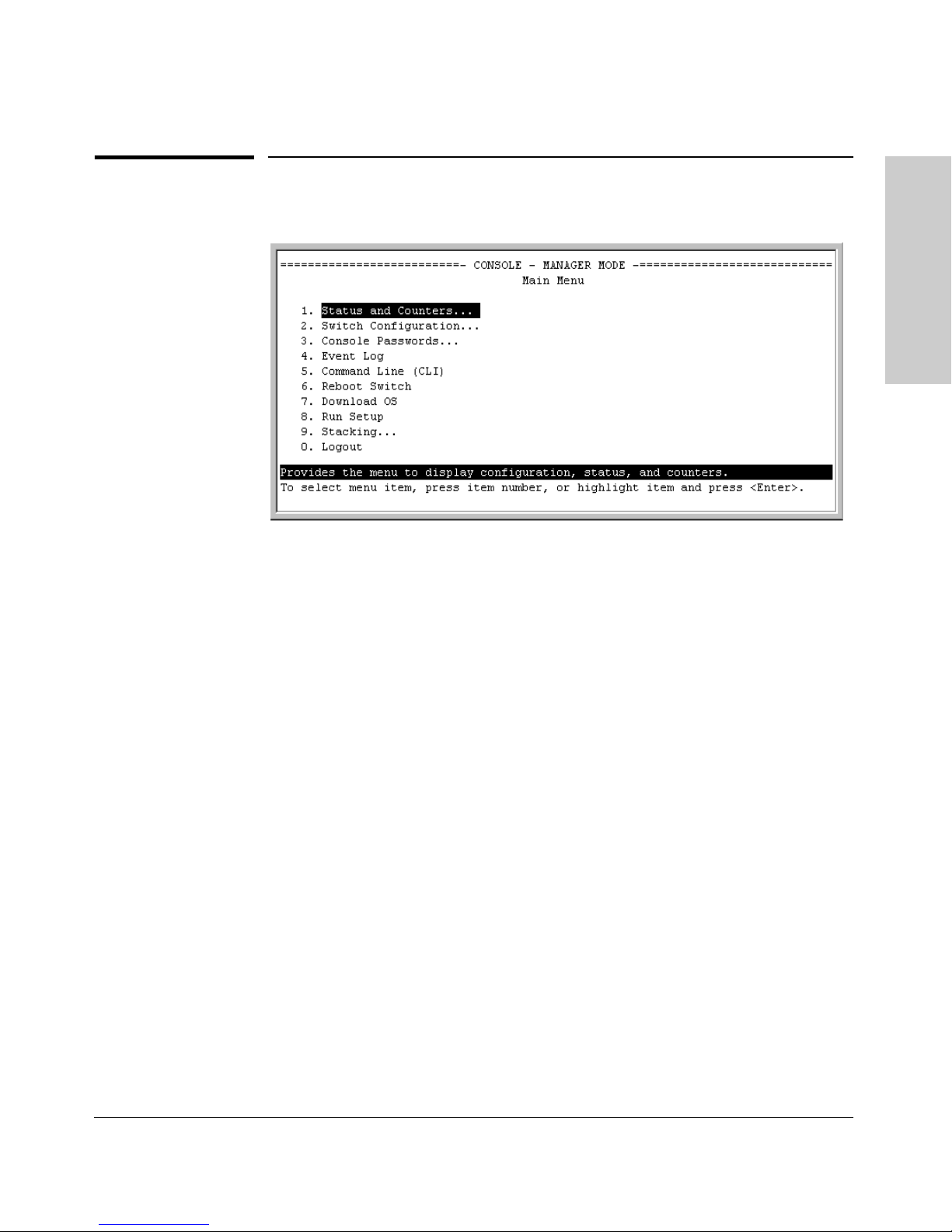
Figure 1-1. Example of the Console Interface Display
Selecting a Management
Interface
■ Provides quick, easy management access to a menu-driven subset of
switch configuration and performance features:
• IP addressing
• VLANs
• Security
• Port and Static Trunk Group
• Stack Management
• Spanning Tree
• System information
• Passwords and other security features
• SNMP communities
The menu interface also provides access for:
• Setup screen
• Event Log display
• Switch and port
status displays
■ Offers out-of-band access (through the RS-232 connection) to the
• Switch and port statistic and counter
displays
• Reboots
• Software downloads
switch, so network bottlenecks, crashes, lack of configured or correct IP
address, and network downtime do not slow or prevent access
■ Enables Telnet (in-band) access to the menu functionality.
■ Allows faster navigation, avoiding delays that occur with slower
display of graphical objects over a web browser interface.
■ Provides more security; configuration information and passwords are
not seen on the network.
1-3
Page 22

Selecting a Management Interface
Advantages of Using the CLI
Advantages of Using the CLI
HP2512>
Interface
HP2512#
HP2512(config)#
Selecting a Management
HP2512(<context>)#
Operator Level
Manager Level
Global Configuration Level
Context Configuration Levels (port, VLAN)
Figure 1-2. Example of The Command Prompt
■ Provides access to the complete set of the switch configuration, perfor-
mance, and diagnostic features.
■ Offers out-of-band access (through the RS-232 connection) or Telnet (in-
band) access.
■ Enables quick, detailed system configuration and management access to
system operators and administrators experienced in command prompt
interfaces.
■ Provides help at each level for determining available options and vari-
ables.
CLI Usage
1-4
■ For information on how to use the CLI, refer to chapter 3. "Using the
Command Line Interface (CLI)".
■ To perform specific procedures (such as configuring IP addressing or
VLANs), use the Contents listing at the front of the manual to locate the
information you need.
■ To monitor and analyze switch operation, see chapter 10, "Monitoring and
Analyzing Switch Operation".
■ For information on individual CLI commands, refer to the Index or to the
"Command Line Interface Reference Guide" available on HP’s ProCurve
website at
http://www.hp.com/go/procurve
Page 23
Selecting a Management Interface
Advantages of Using the HP Web Browser Interface
Advantages of Using the HP Web
Browser Interface
Selecting a Management
Interface
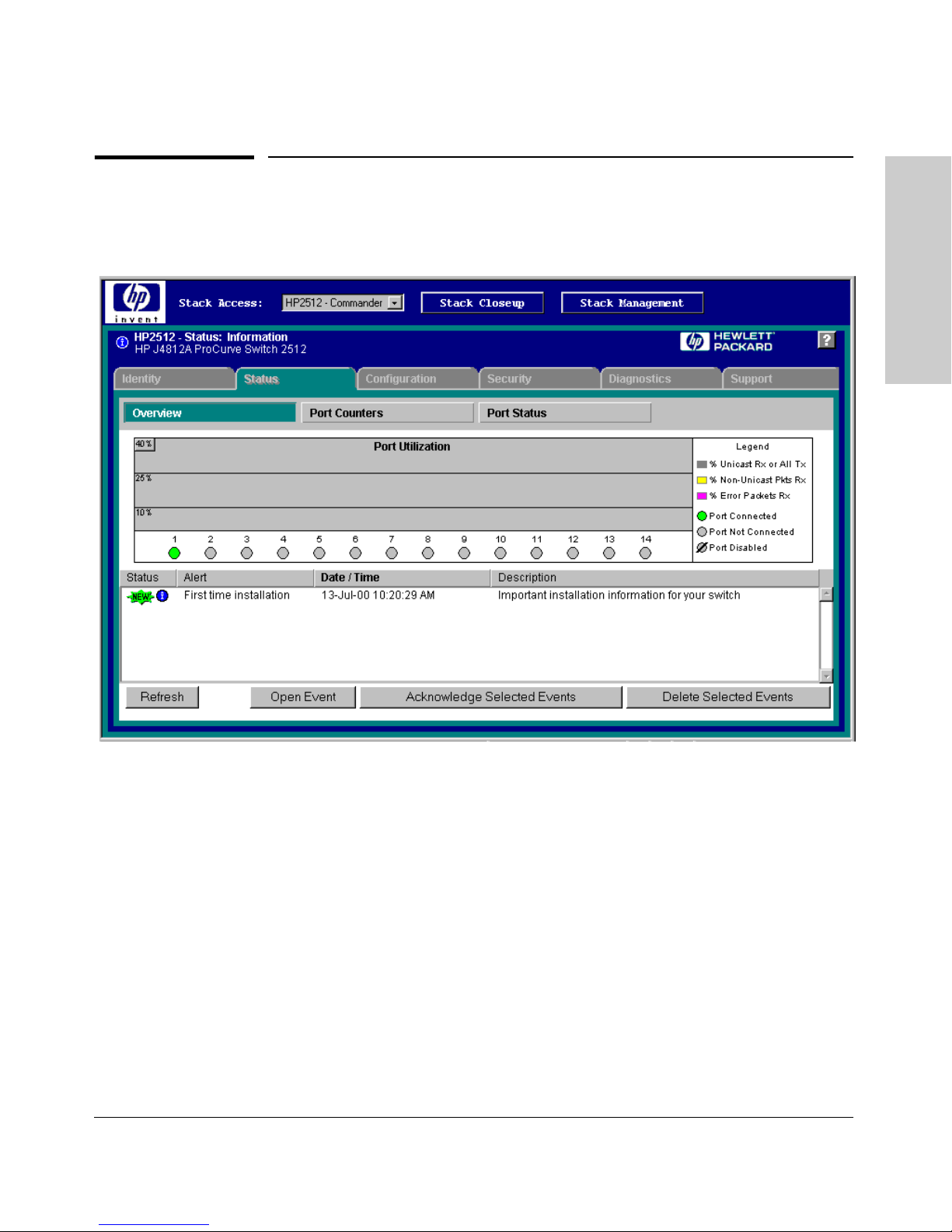
Figure 1-3. Example of the HP Web Browser Interface
■ Easy access to the switch from anywhere on the network
■ Familiar browser interface--locations of window objects consistent
with commonly used browsers, uses mouse clicking for navigation, no
terminal setup
■ Many features have all their fields in one screen so you can view all
values at once
■ More visual cues, using colors, status bars, device icons, and other
graphical objects instead of relying solely on alphanumeric values
■ Display of acceptable ranges of values available in configuration list
boxes
For specific requirements, see “Web Browser Interface Requirements” on page
4-4.
1-5
Page 24
Selecting a Management Interface
Advantages of Using HP TopTools for Hubs & Switches
Advantages of Using HP TopTools for
Hubs & Switches
Interface
Selecting a Management
You can operate HP TopTools from a PC on the network to monitor traffic,
manage your hubs and switches, and proactively recommend network
changes to increase network uptime and optimize performance. Easy to install
and use, HP TopTools for Hubs & Switches is the answer to your management
challenges.
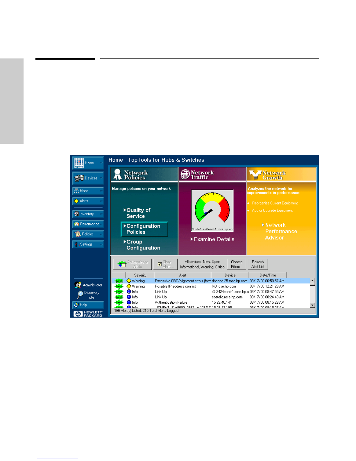
Figure 1-4. Example of HP TopTools Main Screen
HP TopTools for Hubs & Switches enables greater control, uptime, and
performance in your network:
■ For networked devices
• Enables fast installation of hubs and switches.
• Enables you to proactively manage your network by using the Alert
1-6
Log to quickly identify problems and suggest solutions, saving valuable time.
Page 25

Selecting a Management Interface
Advantages of Using HP TopTools for Hubs & Switches
• Notifies you when HP hubs use “self-healing” features to fix or limit
common network problems.
• Provides a list of discovered devices, with device type, connectivity
status, the number of new or open alerts for each device, and the type
of management for each device.
• Provides graphical maps of your networked devices, from which you
can access specific devices.
• Identifies users by port and lets you assign easy-to-remember names
to any network device.
• Enables you to configure and monitor HP networked devices from
your network management PC, including identity and status information, port counters, port on/off capability, sensitivity thresholds for
traps, IP and security configuration, device configuration report, and
other device features.
• Enables policy-based management through the Quality of Service
feature (QoS) to establish traffic priority policies for controlling and
improving throughput across all the HP switches in your network that
support this feature.
■ For network traffic:
• Watches the network for problems and displays real-time information
about network status.
• Shows traffic and “top talker” nodes on screen.
• Uses traffic monitor diagrams to make bottlenecks easy to see.
• Improves network reliability through real-time fault isolation.
• Lets you see your entire network without having to put RMON probes
on every segment (up to 1500 segments).
■ For network growth:
• Monitors, stores, and analyzes network traffic to determine where
upgrades are needed.
• Uses Network Performance Advisor for automatic traffic analysis
and easy-to-understand reports that give clear, easy-to-follow plans
for cost-effectivly upgrading your network.
Selecting a Management
Interface
1-7
Page 26

Selecting a Management Interface
Advantages of Using HP TopTools for Hubs & Switches
Interface
Selecting a Management
1-8
Page 27

Using the Menu Interface
Chapter Contents
Overview . . . . . . . . . . . . . . . . . . . . . . . . . . . . . . . . . . . . . . . . . . . . . . . . . . . . . 2-2
Starting and Ending a Menu Session . . . . . . . . . . . . . . . . . . . . . . . . . . . 2-3
2
Main Menu Features . . . . . . . . . . . . . . . . . . . . . . . . . . . . . . . . . . . . . . . . . . 2-7
Screen Structure and Navigation . . . . . . . . . . . . . . . . . . . . . . . . . . . . . . . 2-9
Rebooting the Switch . . . . . . . . . . . . . . . . . . . . . . . . . . . . . . . . . . . . . . . . . 2-12
Menu Features List . . . . . . . . . . . . . . . . . . . . . . . . . . . . . . . . . . . . . . . . . . . 2-14
Where To Go From Here . . . . . . . . . . . . . . . . . . . . . . . . . . . . . . . . . . . . . . 2-15
Using the Menu Interface
2-1
Page 28

Using the Menu Interface
Overview
Overview
This chapter describes the following features:
■ Overview of the Menu Interface (page 4-1)
■ Starting and ending a Menu session (page 2-3)
■ The Main Menu (page 2-7)
■ Screen structure and navigation (page 2-9)
■ Rebooting the switch (page 2-12)
The menu interface operates through the switch console to provide you with
a subset of switch commands in an easy-to-use menu format enabling you to:
■ Perform a "quick configuration" of basic parameters, such as the IP
addressing needed to provide management access through your network
■ Configure these features:
• Manager and Operator passwords
Using the Menu Interface
• System parameters
• IP addressing
• Ports
• One trunk group
■ View status, counters, and Event Log information
■ Download new software system
■ Reboot the switch
• A network monitoring port
• Stack Management
• Spanning Tree operation
• SNMP community names
• IP authorized managers
• VLANs (Virtual LANs)
For a detailed list of menu features, see the "Menu Features List" on page 2-14.
Privilege Levels and Password Security. HP strongly recommends that
you configure a Manager password to help prevent unauthorized access to
your network. A Manager password grants full read-write access to the switch.
An Operator password, if configured, grants access to status and counter,
Event Log, and the Operator level in the CLI. After you configure passwords
on the switch and log off of the interface, access to the menu interface (and
the CLI and web browser interface) will require entry of either the Manager
or Operator password. (If the switch has only a Manager password, then
someone without a password can still gain read-only access.) For more
information on passwords, see "Using Password Security" on .
2-2
Page 29

Using the Menu Interface
Starting and Ending a Menu Session
Menu Interaction with Other Interfaces.
■ A configuration change made through any switch interface overwrites
earlier changes made through any other interface.
■ The Menu Interface and the CLI (Command Line Interface) both use the
switch console. To enter the menu from the CLI, use the
To enter the CLI from the Menu interface, select
Command Line (CLI) option.)
menu command.
Starting and Ending a Menu Session
You can access the menu interface using any of the following:
■ A direct serial connection to the switch’s console port, as described in the
installation guide you received with the switch
■ A Telnet connection to the switch console from a networked PC or the
switch’s web browser interface. Telnet requires that an IP address and
subnet mask compatible with your network have already been configured
on the switch.
■ The stack Commander, if the switch is a stack member
Using the Menu Interface
Note This section assumes that either a terminal device is already configured and
connected to the switch (see the Installation Guide shipped with your switch)
or that you have already configured an IP address on the switch (required for
Telnet access).
2-3
Page 30

Using the Menu Interface
Starting and Ending a Menu Session
How To Start a Menu Interface Session
In its factory default configuration, the switch console starts with the CLI
prompt. To use the menu interface with Manager privileges, go to the Manager
level prompt and enter the
1. Use one of these methods to connect to the switch:
• A PC terminal emulator or terminal
• Telnet
(You can also use the stack Commander if the switch is a stack member.
See "HP ProCurve Stack Management" on ).
2. Do one of the following:
• If you are using Telnet, go to step 3.
• If you are using a PC terminal emulator or a terminal, press [Enter] one
3. When the switch screen appears, do one of the following:
• If a password has been configured, the password prompt appears.
menu command.
or more times until a prompt appears.
Password: _
Using the Menu Interface
Type the Manager password and press [Enter]. Entering the Manager
password gives you manager-level access to the switch. (Entering the
Operator password gives you operator-level access to the switch. See
"Using Password Security" on .)
• If no password has been configured, the CLI prompt appears . Go to
the next step.
4. When the CLI prompt appears, display the Menu interface by entering the
menu command. For example:
HP2512# menu [Enter]
results in:
2-4
Page 31
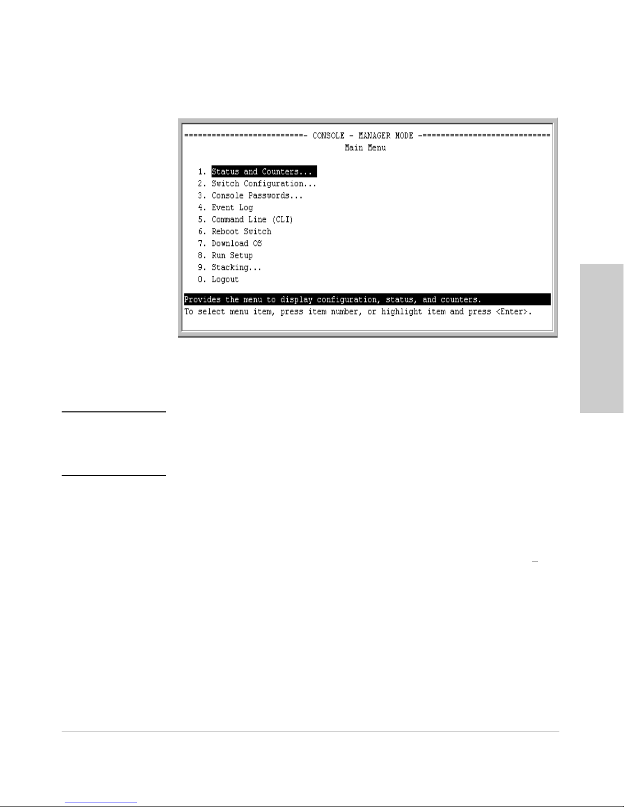
Starting and Ending a Menu Session
Figure 2-1. The Main Menu with Manager Privileges
Using the Menu Interface
Using the Menu Interface
For a description of Main Menu features, see “Main Menu Features” on page
2-7.
Note To configure the switch to start with the menu interface instead of the CLI, go
to the Manager level prompt, enter the
desplay, change the
Logon Default parameter to Menu. For more information, see
the Installation and Getting Started Guide you received with the switch.
setup command, and in the resulting
How To End a Menu Session and Exit from the Console:
The method for ending a menu session and exiting from the console depends
on whether, during the session, you made any changes to the switch configuration that require a switch reboot to activate. (Most changes need only a S
and do not require a switch reboot.) Configuration changes needing a reboot
are marked with an asterisk (*) next to the configured item in the Configuration menu and also next to the Switch Configuration item in the Main Menu.
ave,
2-5
Page 32
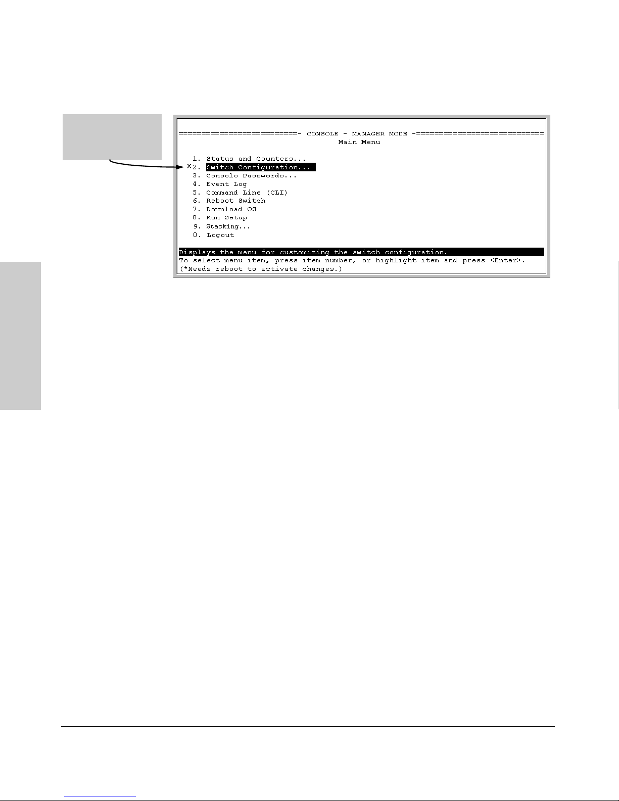
Using the Menu Interface
Starting and Ending a Menu Session
Asterisk indicates a
configuration change
that requires a reboot
to activate.
Figure 2-2. An Asterisk Indicates a Configuration Change Requiring a Reboot
1. In the current session, if you have not made configuration changes that
require a switch reboot to activate, return to the Main menu and press [0]
(zero) to log out. Then just exit from the terminal program, turn off the
terminal, or quit the Telnet session.
2. If you have made configuration changes that require a switch reboot—
Using the Menu Interface
that is, if an asterisk (*) appears next to a configured item or next to Switch
Configuration in the Main menu:
a. Return to the Main menu.
b. Press [6] to select Reboot Switch and follow the instructions on the
reboot screen.
Rebooting the switch terminates the menu session, and, if you are using
Telnet, disconnects the Telnet session.
(See “Rebooting To Activate Configuration Changes” on page 2-13.)
3. Exit from the terminal program, turn off the terminal, or close the Telnet
application program.
2-6
Page 33
Main Menu Features
Using the Menu Interface
Main Menu Features
Using the Menu Interface
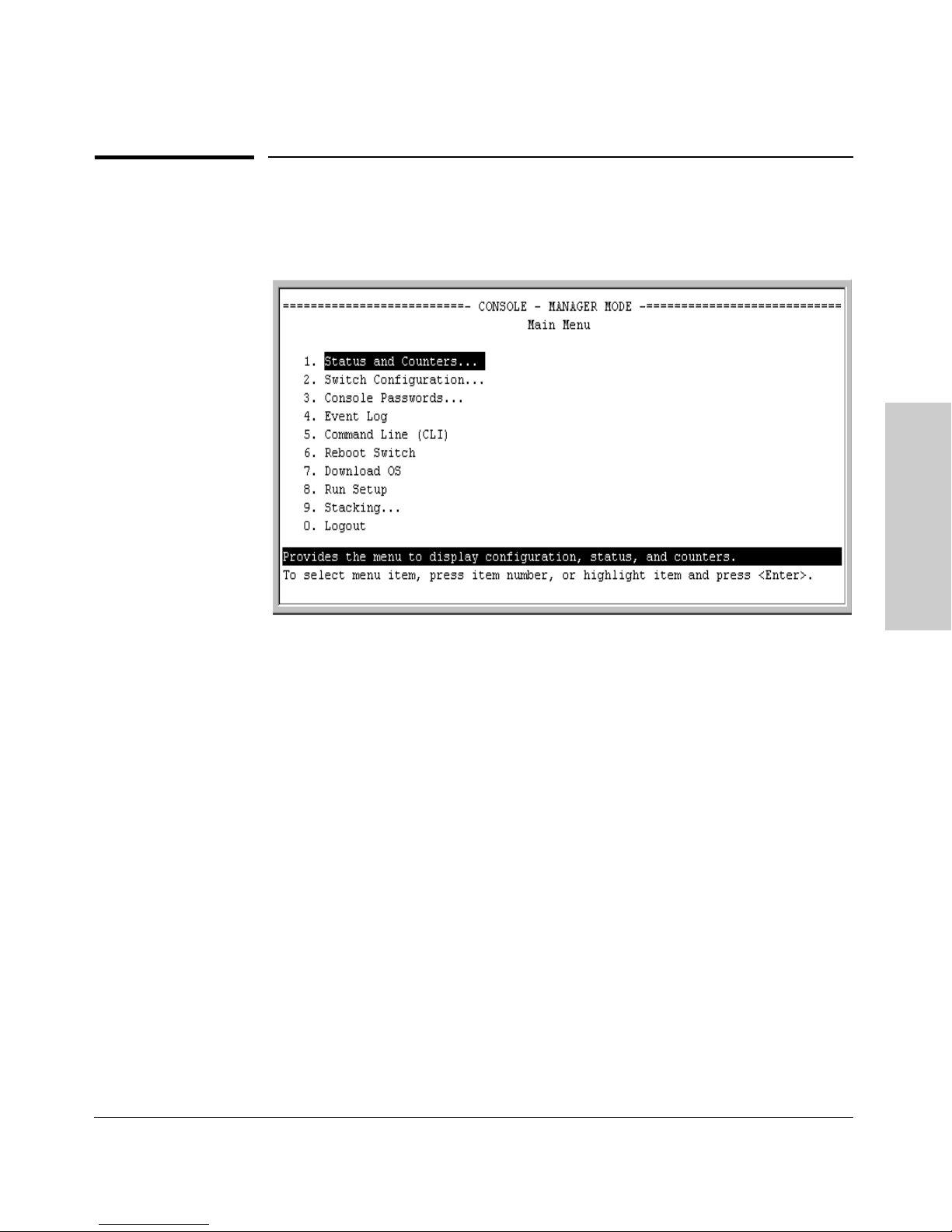
Figure 2-3. The Main Menu View with Manager Privileges
The Main Menu gives you access to these Menu interface features:
■ Status and Counters: Provides access to display screens showing
switch information, port status and counters, port and VLAN address
tables, and spanning tree information. (See chapter 10, “Monitoring and
Analyzing Switch Operation”.)
■ Switch Configuration: Provides access to configuration screens for
displaying and changing the current configuration settings. (See the Contents listing at the front of this manual.) For a listing of features and
parameters configurable through the menu interface, see the "Menu Features List" on page 2-14 .
■ Console Passwords: Provides access to the screen used to set or change
Manager-level and Operator-level passwords, and to delete Manager and
Operator password protection. (See "Using Password Security" on page
page 7-4.)
■ Event Log: Enables you to read progress and error messages that are
useful for checking and troubleshooting switch operation. (See “Using the
Event Log To Identify Problem Sources” on page 11-11.)
2-7
Page 34

Using the Menu Interface
Main Menu Features
■ Command Line (CLI): Selects the Command Line Interface at the same
level (Manager or Operator) that you are accessing in the Menu interface.
(See chapter 3, "Using the Command Line Interface (CLI)".)
■ Reboot Switch: Performs a "warm" reboot of the switch, which clears
most temporary error conditions, resets the network activity counters to
zero, and resets the system up time to zero. A reboot is required to activate
a change in the VLAN Support parameter. (See “Rebooting from the Menu
Interface” on page C-9.)
■ Download OS: Enables you to download a new software version to the
switch. (See appendix A, “Transferring an Operating System or Configuration”.)
■ Run Setup: Displays the Switch Setup screen for quickly configuring
basic switch parameters such as IP addressing, default gateway, logon
default interface, spanning tree, and others. (See the Installation and
Getting Started guide shipped with your switch.)
■ Stacking: Enables you to use a single IP address and standard network
cabling to manage a group of up to 16 switches in the same subnet
(broadcast domain). See “HP ProCurve Stack Management” on page 9-5.
■ Logout: Closes the Menu interface and console session, and disconnects
Using the Menu Interface
Telnet access to the switch. (See “How to End a Menu Session and Exit
from the Console” on page 2-5.)
2-8
Page 35
Using the Menu Interface
Screen Structure and Navigation
Screen Structure and Navigation
Menu interface screens include these three elements:
■ Parameter fields and/or read-only information such as statistics
■ Navigation and configuration actions, such as Save, Edit, and Cancel
■ Help line to describe navigation options, individual parameters, and read-
only data
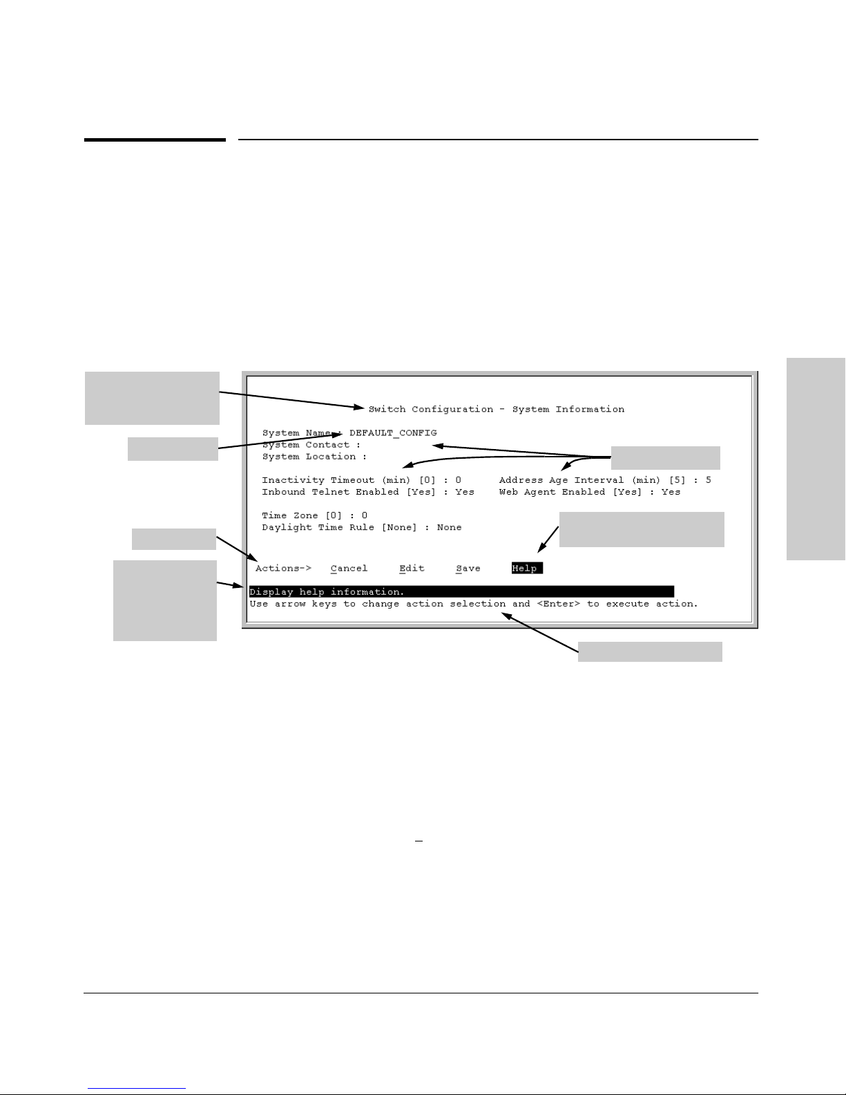
For example, in the following System Information screen:
Screen title – identifies
the location within the
menu structure
System name
Actions line
Help line
describing the
selected action
or selected
parameter field
Using the Menu Interface
Parameter fields
Help describing each of the
items in the parameter fields
Navigation instructions
Figure 4-1. Elements of the Screen Structure
“Forms” Design. The configuration screens, in particular, operate similarly
to a number of PC applications that use forms for data entry. When you first
enter these screens, you see the current configuration for the item you have
selected. To change the configuration, the basic operation is to:
1. Press [E] to select the E
2. Navigate through the screen making all the necessary configuration
changes. (See Table 4-1 on the next page.)
3. Press [Enter] to return to the Actions line. From there you can save the
configuration changes or cancel the changes. Cancel returns the configuration to the values you saw when you first entered the screen.
dit action.
2-9
Page 36

Using the Menu Interface
Screen Structure and Navigation
Table 4-1. How To Navigate in the Menu Interface
Task: Actions:
Execute an action
from the “Actions –>”
list at the bottom of
the screen:
Reconfigure (edit) a
parameter setting or a
field:
Using the Menu Interface
Use either of the following methods:
• Use the arrow keys ( [<] ,or [>] ) to highlight the action you want
to execute, then press [Enter].
• Press the key corresponding to the capital letter in the action
name. For example, in a configuration menu, press [E] to select
Edit and begin editing parameter values.
1. Select a configuration item, such as System Name. (See figure
4-1.)
2. Press [E] (for E
3. Use [Tab] or the arrow keys ([<], [>], [^], or [v]) to highlight the
item or field.
4. Do one of the following:
– If the parameter has preconfigured values, either use the
Space bar to select a new option or type the first part of your
selection and the rest of the selection appears automatically.
(The help line instructs you to “Select” a value.)
– If there are no preconfigured values, type in a value (the Help
line instructs you to “Enter” a value).
5. If you want to change another parameter value, return to step 3.
6. If you are finished editing parameters in the displayed screen,
press [Enter] to return to the Actions line and do one of the
following:
– To save and activate configuration changes, press [S] (for the
Save action). This saves the changes in the startup
configuration and also implements the change in the
currently running configuration. (See appendix C, "Switch
Memory and Configuration.)
– To exit from the screen without saving any changes that you
have made (or if you have not made changes), press [C] (for
the Cancel action).
Note: In the menu interface, executing Save activates most
parameter changes and saves them in the startup configuration
(or flash) memory, and it is therefore not necessary to reboot the
switch after making these changes. But if an asterisk appears
next to any menu item you reconfigure, the switch will not
activate or save the change for that item until you reboot the
switch. In this case, rebooting should be done after you have
made all desired changes and then returned to the Main Menu.
7. When you finish editing parameters, return to the Main Menu.
8. If necessary, reboot the switch by highlighting Reboot Switch in
the Main Menu and pressing [Enter]. (See the Note, above.)
dit on the Actions line).
Exit from a read-only
screen.
2-10
Press [B] (for the Back action).
Page 37
Highlight on any item
in the Actions line
indicates that the
Actions line is active.
Using the Menu Interface
Screen Structure and Navigation
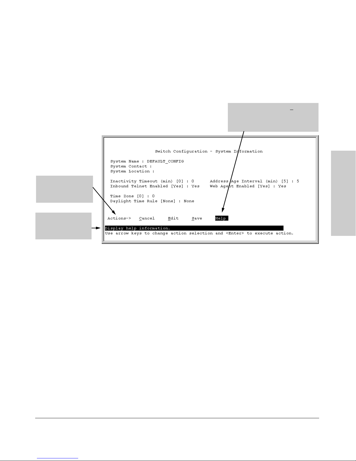
To get Help on individual parameter descriptions. In most screens
there is a Help option in the Actions line. Whenever any of the items in the
Actions line is highlighted, press [H], and a separate help screen is displayed.
For example:
Pressing [H] or highlighting Help and
pressing [Enter] displays Help for the
parameters listed in the upper part of
the screen
Using the Menu Interface
The Help line provides
a brief descriptor of
the highlighted Action
item or parameter.
Figure 4-2. Example Showing How To Display Help
To get Help on the actions or data fields in each screen: Use the arrow
keys ( [<], [>], [^], or [v]) to select an action or data field. The help line under
the Actions items describes the currently selected action or data field.
For guidance on how to navigate in a screen: See the instructions provided
at the bottom of the screen, or refer to “Screen Structure and Navigation” on
page 2-9.)
2-11
Page 38
Using the Menu Interface
Rebooting the Switch
Rebooting the Switch
Rebooting the switch from the menu interface
■ Terminates all current sessions and performs a reset of the operating
system
■ Activates any configuration changes that require a reboot
■ Resets statistical counters to zero
(Note that statistical counters can be reset to zero without rebooting the
switch.)
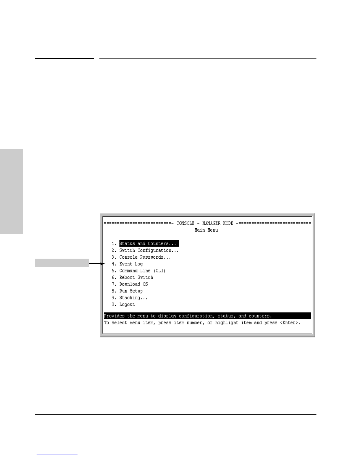
To Reboot the switch, use the Reboot Switch option in the Main Menu. (Note
that the Reboot Switch option is not available if you log on in Operator mode;
that is, if you enter an Operator password instead of a manager password at
the password prompt.)
Using the Menu Interface
Reboot Switch option
Figure 4-3. The Reboot Switch Option in the Main Menu
2-12
Page 39
Asterisk indicates
a configuration
change that
requires a reboot
in order to take
effect.
Using the Menu Interface
Rebooting the Switch
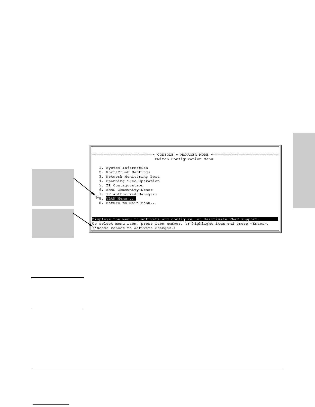
Rebooting To Activate Configuration Changes. Configuration changes
for most parameters become effective as soon as you save them. However,
you must reboot the switch in order to implement a change in the
VLANs to support parameter
select 2. Switch Configuration, then 8. VLAN Menu, then
. (To access this parameter, go to the Main menu and
1. VLAN Support.)
Maximum
If configuration changes requiring a reboot have been made, the switch
displays an asterisk (*) next to the menu item in which the change has been
made. For example, if you change and save the value for the Maximum VLANs to
support
VLAN Menu screen, and also next to the the
parameter, an asterisk appears next to the VLAN Support entry in the
Switch Configuration . . . entry in the
Main menu, as shown in figure 4-6:
Using the Menu Interface
Reminder to
reboot the switch
to activate
configuration
changes.
Figure 4-4. Indication of a Configuration Change Requiring a Reboot
To activate changes indicated by the asterisk, go to the Main Menu and select
the
Reboot Switch option.
Note Executing the write memory command in the CLI does not affect pending
configuration changes indicated by an asterisk in the menu interface. That is,
only a reboot from the menu interface or a boot or reload command from the
CLI will activate a pending configuration change indicated by an asterisk.
2-13
Page 40

Using the Menu Interface
Menu Features List
Menu Features List
Status and Counters
• General System Information
• Switch Management Address Information
• Port Status
• Port Counters
• Address Table
• Port Address Table
• Spanning Tree Information
Switch Configuration
• System Information
• Port/Trunk Settings
• Network Monitoring Port
• Spanning Tree Operation
Using the Menu Interface
• IP Configuration
• SNMP Community Names
• IP authorized Managers
• VLAN Menu
Console Passwords
Event Log
Command Line (CLI)
Reboot Switch
Download OS
Run Setup
Stacking
• Stacking Status (This Switch)
• Stacking Status (All)
• Stack Configuration
• Stack Management (Available in Stack Commander Only)
• Stack Access (Available in Stack Commander Only)
Logout
2-14
Page 41

Using the Menu Interface
Where To Go From Here
Where To Go From Here
This chapter provides an overview of the menu interface and how to use it.
The following table indicates where to turn for detailed information on how
to use the individual features available through the menu interface.
Option Wh ere To Turn
To use the Run Setup option See the Installation and Getting Started Guide
shipped with the switch.
To use the ProCurve Stack Manager “HP ProCurve Stack Management” on page 9-5
To view and monitor switch status and
counters
To learn how to configure and use
passwords
To learn how to use the Event Log "Using the Eve nt Log To Identif y Problem Sources"
To learn how the CLI operates Chapter 3, "Using the Command Line Interface
To download software (the OS) Appendix A, "File Transfers"
For a description of how switch
memory handles configuration
changes
For information on other switch
features and how to configure them
Chapter 10, "Monitoring and Analyzing Switch
Operation"
"Using Password Security" on page 7-4
on page 11-11
(CLI)"
Appendix C, "Switch Memory and Configuration"
See the Table of Contents at the front of this
manual.
Using the Menu Interface
2-15
Page 42

Using the Menu Interface
Where To Go From Here
Using the Menu Interface
2-16
Page 43

Using the Command Line Interface (CLI)
Chapter Contents
Overview. . . . . . . . . . . . . . . . . . . . . . . . . . . . . . . . . . . . . . . . . . . . . . . . . . . . . . . 3-2
Accessing the CLI . . . . . . . . . . . . . . . . . . . . . . . . . . . . . . . . . . . . . . . . . . . . . . . 3-2
Using the CLI . . . . . . . . . . . . . . . . . . . . . . . . . . . . . . . . . . . . . . . . . . . . . . . . . . 3-2
Privilege Levels at Logon. . . . . . . . . . . . . . . . . . . . . . . . . . . . . . . . . . . . . . 3-3
Privilege Level Operation . . . . . . . . . . . . . . . . . . . . . . . . . . . . . . . . . . . . . 3-4
Operator Privileges . . . . . . . . . . . . . . . . . . . . . . . . . . . . . . . . . . . . . . 3-4
Manager Privileges . . . . . . . . . . . . . . . . . . . . . . . . . . . . . . . . . . . . . . . 3-5
Changing Interfaces . . . . . . . . . . . . . . . . . . . . . . . . . . . . . . . . . . . 3-6
How To Move Between Levels . . . . . . . . . . . . . . . . . . . . . . . . . . . . . . . . 3-7
Moving Between the CLI and the Menu Interface. . . . . . . . . . . . . 3-7
Changing Parameter Settings . . . . . . . . . . . . . . . . . . . . . . . . . . . . .
Listing Commands and Command Options . . . . . . . . . . . . . . . . . . . . . . 3-8
Listing Commands Available at Any Privilege Level . . . . . . . . . . . 3-8
Type "?" To List Available Commands . . . . . . . . . . . . . . . . . . . . 3-8
Use
[Tab] To Search for or Complete a Command Word . . . . . . . . 3-9
Command Option Displays . . . . . . . . . . . . . . . . . . . . . . . . . . . . . . . 3-10
Conventions for Command Option Displays . . . . . . . . . . . . . . . 3-10
Listing Command Options
Displaying CLI "Help" . . . . . . . . . . . . . . . . . . . . . . . . . . . . . . . . . . . . . . . 3-11
Displaying Command-List Help . . . . . . . . . . . . . . . . . . . . . . . . . 3-11
Displaying Help for an Individual Command
Configuration Commands and the Context Configuration Modes . . 3-13
Port or Trunk-Group Context . . . . . . . . . . . . . . . . . . . . . . . . . . . 3-13
VLAN Context
. . . . . . . . . . . . . . . . . . . . . . . . . . . . . . . . . . . . . . 3-15
. . . . . . . . . . . . . . . . . . . . . . . . . . . . . 3-11
. . . . . . . . . . . . . . . 3-12
3
Using the Command Line
Interface (CLI)
3-7
CLI Control and Editing . . . . . . . . . . . . . . . . . . . . . . . . . . . . . . . . . . . . . . . . . 3-16
3-1
Page 44

Using the Command Line Interface (CLI)
Overview
Overview
The CLI is a text-based command interface for configuring and monitoring the
switch. The CLI gives you access to the switch’s full set of commands while
providing the same password protection that is used in the web browser
interface and the menu interface.
Accessing the CLI
Like the menu interface, the CLI is accessed through the switch console, and,
in the switch’s factory default state, is the default interface when you start a
console session. You can access the console out-of-band by directly
connecting a terminal device to the switch, or in-band by using Telnet either
from a terminal device or through the web browser interface.
Also, if you are using the menu interface, you can access the CLI by selecting
the Command Line (CLI) option in the Main Menu.
Interface (CLI)
Using the Command Line
Using the CLI
The CLI offers these privilege levels to help protect the switch from unauthorized access:
• Operator
• Manager
• Global Configuration
• Context Configuration
Note CLI commands are not case-sensitive.
When you use the CLI to make a configuration change, the switch writes the
change to the Running-Config file in volatile memory. This allows you to test
your configuration changes before making them permanent. to make changes
permanent, you must use the write memory command to save them to the
Startup Config file in non-volatile memory. If you reboot the switch without
3-2
Page 45
Using the Command Line Interface (CLI)
Using the CLI
first using write memory, all changes made since the last reboot or write memory
(whichever is later) will be lost. For more on switch memory and saving
configuration changes, see appendix C, "Switch Memory and Configuration".
Privilege Levels at Logon
Privilege levels control the type of access to the CLI. To implement this
control, you must set at least a Manager password. Without a Manager
password configured, anyone having serial port, Telnet, or web browser
access to the switch can reach all CLI levels. (For more on setting passwords,
see "Using Password Security" on page 7-4.)
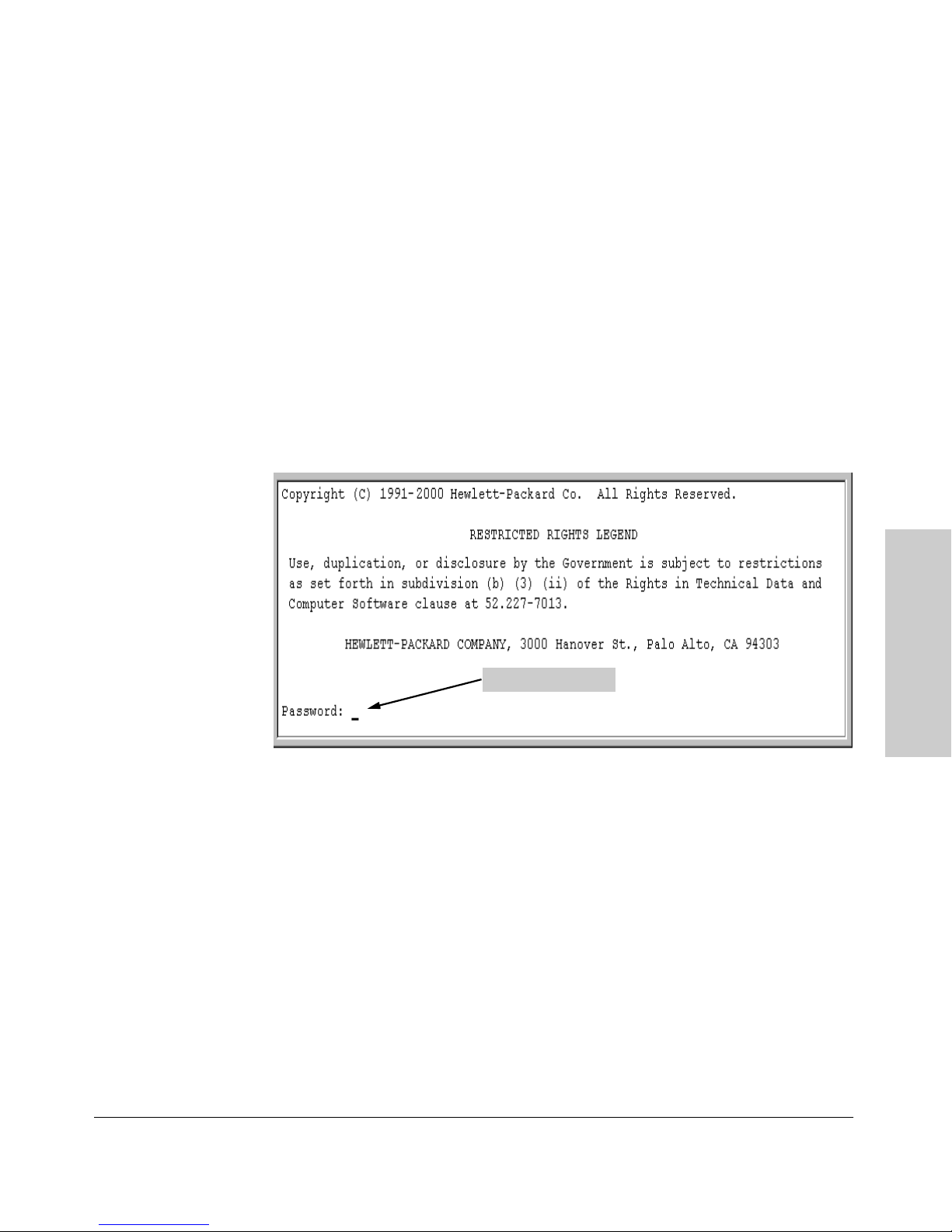
When you use the CLI to log on to the switch, and passwords are set, you will
be prompted to enter a password. For example:
Password Prompt
Figure 3-1. Example of CLI Log-On Screen with Password(s) Set
In the above case, you will enter the CLI at the level corresponding to the
password you provide (operator or manager).
If no passwords are set when you log onto the CLI, you will enter at the
Manager level. For example:
HP2512# _
Using the Command Line
Interface (CLI)
3-3
Page 46
Using the Command Line Interface (CLI)
Using the CLI
Caution HP strongly recommends that you configure a Manager password. If a Man-
ager password is not configured, then the Manager level is not passwordprotected, and anyone having in-band or out-of-band access to the switch may
be able to reach the Manager level and compromise switch and network
security. Note that configuring only an Operator password does not prevent
access to the Manager level by intruders who have the Operator password.
Pressing the Clear button on the front of the switch removes password
protection. For this reason, it is recommended that you protect the switch
from physical access by unauthorized persons. If you are concerned about
switch security and operation, you should install the switch in a secure
location, such as a locked wiring closet.
Privilege Level Operation
Operator Privileges
Manager Privileges
Interface (CLI)
Using the Command Line
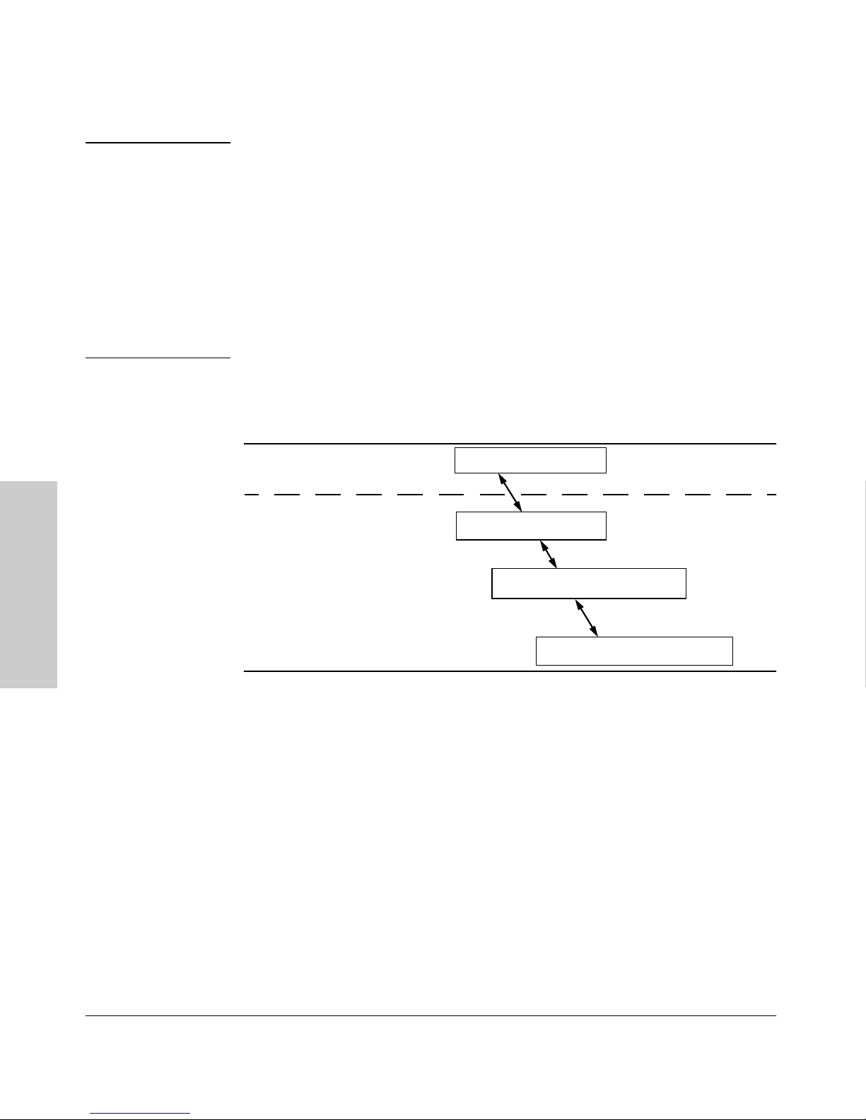
Figure 3-2. Privilege Level Access Sequence
Operator Level
Manager Level
Global Configuration Level
Context Configuration Level
Operator Privileges
At the Operator level you can examine the current configuration and move
between interfaces without being able to change the configuration. A ">"
character delimits the Operator-level prompt. For example:
HP2512> _ (Example of the Operator prompt.)
When using enable to move to the Manager level, the switch prompts you for
the Manager password if one has already been configured.
3-4
Page 47

Using the Command Line Interface (CLI)
Using the CLI
Manager Privileges
Manager privileges give you three additional levels of access: Manager, Global
Configuration, and Context Configuration. (See figure .) A "#" character
delimits any Manager prompt. For example:
HP2512#_ (Example of the Manager prompt.)
■ Manager level: Provides all Operator level privileges plus the ability to
perform system-level actions that do not require saving changes to the
system configuration file. The prompt for the Manager level contains only
the system name and the "#" delimiter, as shown above. To select this
level, enter the enable command at the Operator level prompt and enter
the Manager password, when prompted. For example:
HP2512> enable (Enter enable at the Operator prompt.)
HP2512# _ (The Manager prompt.)
■ Global Configuration level: Provides all Operator and Manager level
privileges, and enables you to make configuration changes to any of the
switch’s software features. The prompt for the Global Configuration level
includes the system name and "(config)". To select this level, enter the
config command at the Manager prompt. For example:
Using the Command Line
Interface (CLI)
HP2512# _ (Enter config at the Manager prompt.)
HP2512(config)#_ (The Global Config prompt.)
■ Context Configuration level: Provides all Operator and Manager
privileges, and enables you to make configuration changes in a specific
context, such as one or more ports or a VLAN. The prompt for the Context
Configuration level includes the system name and the selected context.
For example:
HP2512(eth-1)#
HP2512(vlan-10)#
The Context level is useful, for example, if you want to execute several
commands directed at the same port or VLAN, or if you want to shorten
the command strings for a specific context area. To select this level, enter
the specific context at the Global Configuration level prompt. For
example, to select the context level for an existing VLAN with the VLAN
ID of 10, you would enter the following command and see the indicated
result:
HP2512(config)# vlan 10
HP2512(vlan-10)#
3-5
Page 48
Using the Command Line Interface (CLI)
Using the CLI
Changing Interfaces. If you change from the CLI to the menu interface, or
the reverse, you will remain at the same privilege level. For example, entering
the menu command from the Operator level of the CLI takes you to the
Operator privilege level in the menu interface.
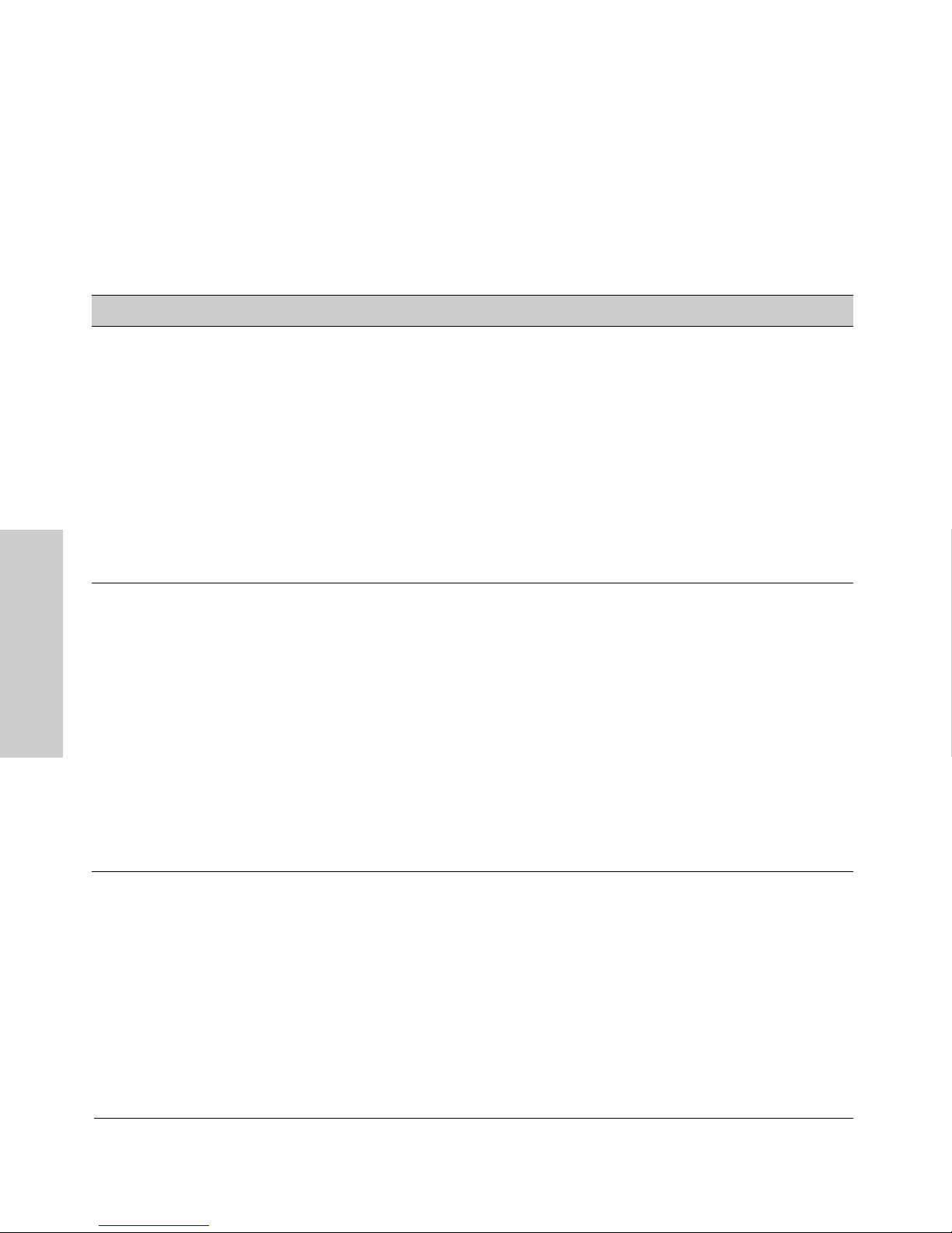
Table 3-1. Privilege Level Hierarchy
Privilege Level Example of Prompt and Permitted Operations
Operator Privilege
Operator Level HP2512> show <command>
View status and configuration information.
setup
ping <argument>
Perform connectivity tests.
link-test <argument>
enable
Move from the Operator level to the Manager level.
Move from the CLI interface to the menu interface.
menu
Exit from the CLI interface and terminate the console
logoff
Manager Privilige
Manager Level HP2512# Perform system-level actions such as system control, monitoring, and diagnostic
commands, plus any of the Operator-level commands. For a list of available
commands, enter
session.
? at the prompt.
Interface (CLI)
Using the Command Line
Global
Configuration
Level
Context
Configuration
Level
HP2512(config)# Execute configuration commands, plus all Operator and Manager commands . For
? at the prompt.
HP2512(eth-5)#
HP2512(vlan-100)#
a list of available commands, enter
Execute context-specific configuration commands, such as a particular VLAN or
switch port. This is useful for shortening the command strings you type, and for
entering a series of commands for the same context. For a list of available
commands, enter
? at the prompt.
3-6
Page 49

Using the Command Line Interface (CLI)
How To Move Between Levels
Change in Levels Example of Prompt , Command, and Result
Using the CLI
Operator level
to
Manager level
Manager level
to
Global configuration
level
Global configuration
level
to a
Context configuration
level
Context configuration
level
to another
Context configuration
level
Move from any level
to the preceding level
HP2512> enable
Password:_
After you enter
appears. After you enter the Manager
password, this prompt appears:
HP2512#_
HP2512# config
HP2512(config)#
HP2512(config)# vlan-10
HP2512(vlan-10)#
HP2512(vlan-10)# interface ethernet 3
HP2512(int-3)#
HP2512(int-3)# exit
HP2512(config)# exit
HP2512# exit
HP2512>
enable, the Password prompt
Using the Command Line
Interface (CLI)
Move from any level
to the Manager level
HP2512(int-3)# end
HP2512#
—or—
HP2512(config)# end
HP2512#
Moving Between the CLI and the Menu Interface. When moving
between interfaces, the switch retains the current privilege level (Manager or
Operator). That is, if you are at the Operator level in the menu and select the
Command Line Interface (CLI) option from the Main Menu, the CLI prompt
appears at the Operator level.
Changing Parameter Settings. Regardless of which interface is used (CLI,
menu interface, or web browser interface), the most recently configured
version of a parameter setting overrides any earlier settings for that parameter.
3-7
Page 50

Using the Command Line Interface (CLI)
Using the CLI
For example, if you use the CLI to set a Manager password, and then later use
the Setup screen (in the menu interface) to set a different Manager password,
then the first password will be replaced by the second one.
Listing Commands and Command Options
At any privilege level you can:
■ List all of the commands available at that level
■ List the options for a specific command
Listing Commands Available at Any Privilege Level
At a given privilege level you can execute the commands that level offers, plus
all of the commands available at preceding levels. Similarly, at a given privilege
level, you can list all of that level’s commands plus the commands made
available at preceding levels. For example, at the Operator level, you can list
and execute only the Operator level commands. However, at the Manager
level, you can list and execute the commands available at both the Operator
and Manager levels.
Type "?" To List Available Commands. Typing the
? symbol lists the
commands you can execute at the current privilege level. For example, typing
? at the Operator level produces this listing:
Interface (CLI)
Using the Command Line
Figure 3-3. Example of the Operator Level Command Listing
3-8
Page 51
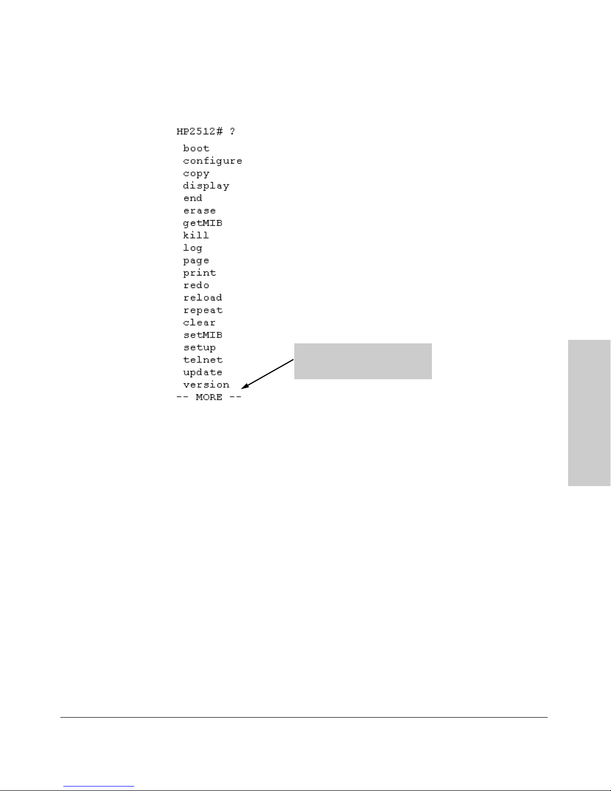
Using the Command Line Interface (CLI)
Typing ? at the Manager level produces this listing:
Using the CLI
When - - MORE - - appears, use
the Space bar or [Return] to list
additional commands.
Figure 3-4. Example of the Manager-Level Command Listing
When - - MORE - - appears, there are more commands in the listing. To list the
next screenfull of commands, press the Space bar. To list the remaining
commands one-by-one, repeatedly press [Enter].
Typing ? at the Global Configuration level or the Context Configuration level
produces similar results.
Use [Tab] To Search for or Complete a Command Word. You can use [Tab]
to help you find CLI commands or to quickly complete the current word in a
command. To do so, press [Tab] immediately after typing the last letter of the
last keyword in the CLI (with no spaces allowed). For example, at the Global
Configuration level, if you press [Tab] immediately after typing "t", the CLI
displays the available command options that begin with "t". For example:
HP2512(config)# t[Tab]
telnet-server
time
trunk
telnet
HP2512(config)# t
Using the Command Line
Interface (CLI)
3-9
Page 52
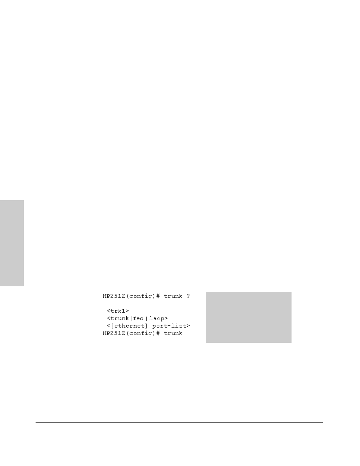
Using the Command Line Interface (CLI)
Using the CLI
As mentioned above, if you type part of a command word and press [Tab], the
CLI completes the current word (if you have typed enough of the word for the
CLI to distinguish it from other possibilities), including hyphenated extensions. For example:
HP2512(config)# port[Tab]
HP2512(config)# port-security _
Pressing [Tab] after a completed command word lists the further options for
that command.
HP2512(config)# stack [Tab]
commander <commander-str>
join <mac-addr>
auto-join
transmission-interval <integer>
<cr>
HP2512(config)# stack
Command Option Displays
Conventions for Command Option Displays. When you use the CLI to
list options for a particular command, you will see one or more of the following
conventions to help you interpret the command data:
■ Braces ( < > ) indicate a required choice.
Interface (CLI)
Using the Command Line
■ Square brackets ([ ]) indicate optional elements.
■ Vertical bars ( | ) separate alternative, mutually exclusive options in a
command.
The braces ( < >) show that the trunk
command requires all three
parameters.
The vertical bar (
trunk or lacp must be included.
The square brackets ([ ]) show that
ethernet is optional.
| ) shows that e ither
Figure 3-5.Example of Command Option Conventions
3-10
Page 53
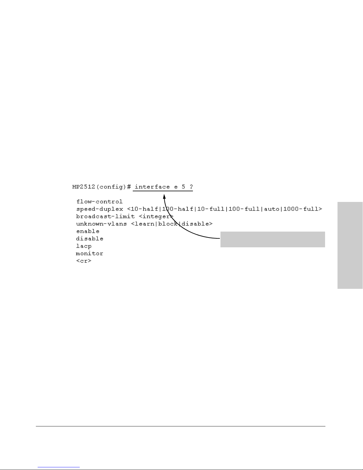
Using the Command Line Interface (CLI)
Using the CLI
Thus, if you wanted to create a port trunk group using ports 5 - 8, the above
conventions show that you could do so using any of the following forms of
the trunk command:
HP2512(config)# trunk trk1 trunk 5-8
HP2512(config)# trunk trk1 trunk e 5-8
HP2512(config)# trunk trk1 lacp 5-8
HP2512(config)# trunk trk1 lacp e 5-8
Listing Command Options. You can use the CLI to remind you of the
options available for a command by entering command keywords followed by
?. For example, suppose you wanted to see the command options for config-
uring port 5:
This example displays the command options
for configuring port 5 on the switch.
Figure 3-6. Example of How To List the Options for a Specific Command
Displaying CLI "Help"
CLI Help provides two types of context-sensitive information:
■ Command list with a brief summary of each command’s purpose
■ Detailed information on how to use individual commands
Displaying Command-List Help. You can display a listing of command
Help summaries for all commands available at the current privilege level. That
is, when you are at the Operator level, you can display the Help summaries
only for Operator-Level commands. At the Manager level, you can display the
Help summaries for both the Operator and Manager levels, and so on.
Using the Command Line
Interface (CLI)
Syntax: help
For example, to list the Operator-Level commands with their purposes:
3-11
Page 54
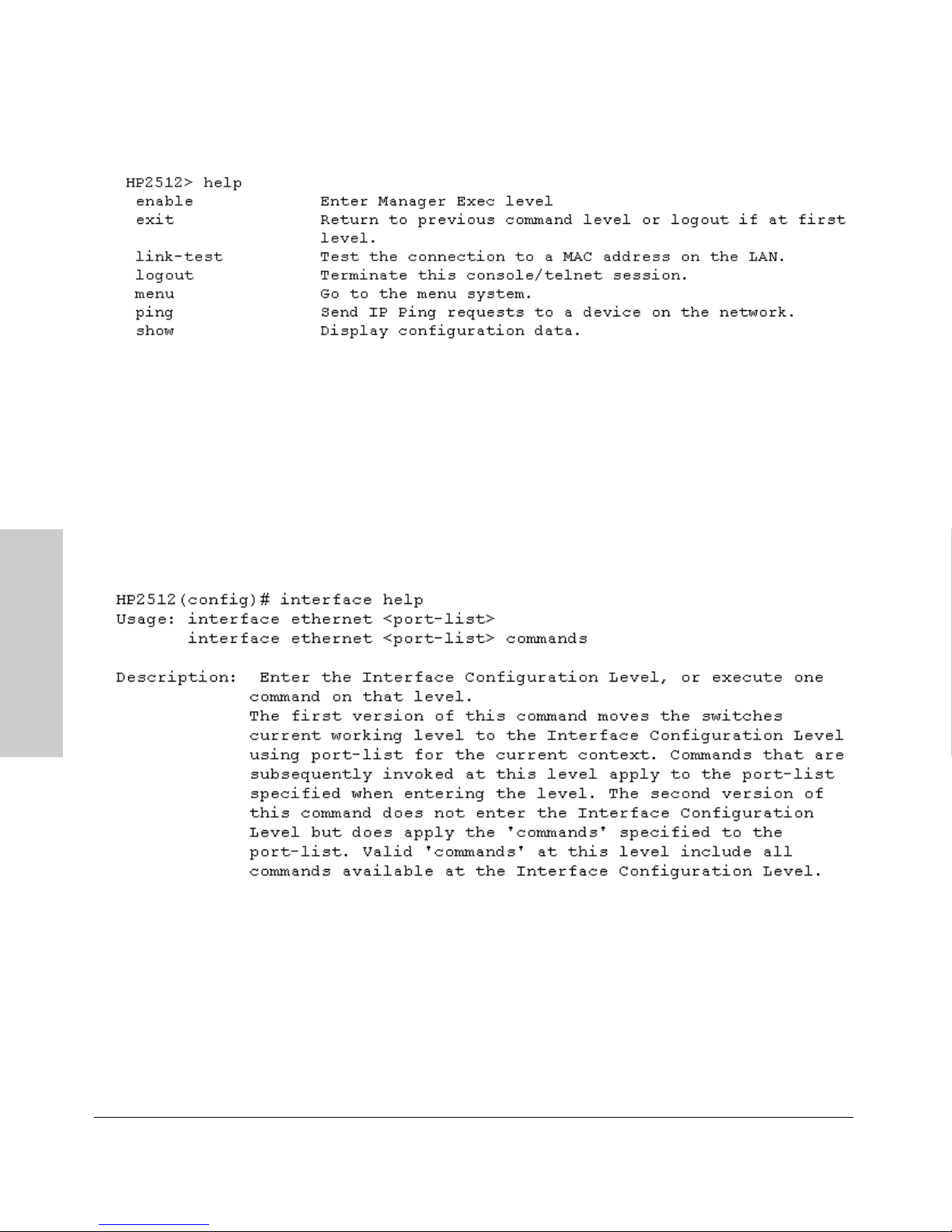
Using the Command Line Interface (CLI)
Using the CLI
Figure 3-7. Example of Context-Sensitive Command-List Help
Displaying Help for an Individual Command. You can display Help for
any command that is available at the current context level by entering enough
of the command string to identify the command, along with help.
Syntax: <command string> help
For example, to list the Help for the interface command in the Global
Configuration privilege level:
Interface (CLI)
Using the Command Line
Figure 3-8. Example of How To Display Help for a Specific Command
A similar action lists the Help showing additional parameter options for a
given command. The following example illustrates how to list the Help for an
interface command acting on a specific port:
3-12
Page 55
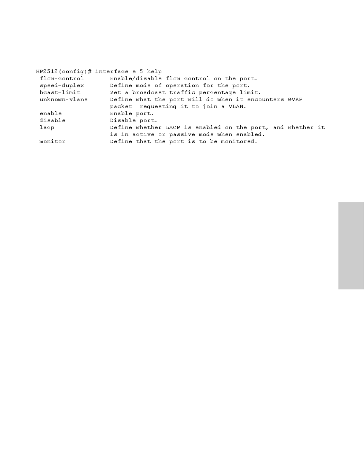
Using the Command Line Interface (CLI)
Using the CLI
Figure 3-9. Example of Help for a Specific Instance of a Command
Note that if you try to list the help for an individual command from a privilege
level that does not include that command, the switch returns an error message.
For example, trying to list the help for the interface command while at the
global configuration level produces this result:
HP2512# interface help
Invalid input: interface
Configuration Commands and the Context
Configuration Modes
You can execute any configuration command in the global configuration mode
or in selected context modes. However, using a context mode enables you to
execute context-specific commands faster, with shorter command strings.
The Switch 2512 and 2524 offer interface (port or trunk group) and VLAN
context configuration modes:
Port or Trunk-Group Context . Includes port- or trunk-specific
commands that apply only to the selected port(s) or trunk group, plus the
global configuration, Manager, and Operator commands. The prompt for this
mode includes the identity of the selected port(s):
HP2512(config)# interface e 5-8
HP2512(config)# interface e trk1
Command executed at
configuration level for
entering port or trk1 static
trunk-group context.
Using the Command Line
Interface (CLI)
HP2512(eth-5-8)#
HP2512(eth-Trk1)#
Resulting prompt showing
port or static trunk contexts.
3-13
Page 56
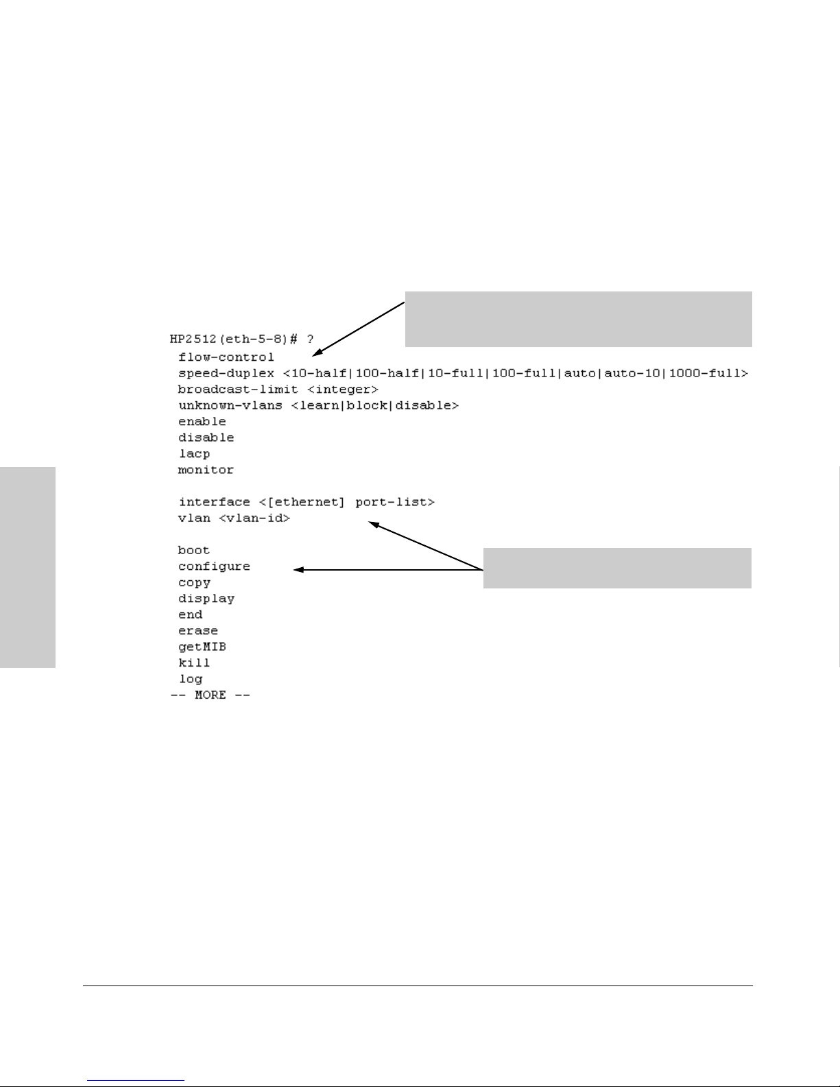
Using the Command Line Interface (CLI)
Using the CLI
HP2512(eth-5-8)# ?
HP2512(eth-5-8)# ?
Lists the commands you can
use in the port or static trunk
context, plus the Manager,
Operator, and context
commands you can execute
at this level.
In the port context, the first block of commands in the "?"
listing show the context-specific commands that will affect
only ports 5-8.
The remaining commands in the listing are
Manager, Operator, and context commands.
Interface (CLI)
Using the Command Line
Figure 3-10. Context-Specific Commands Affecting Port Context
3-14
Page 57
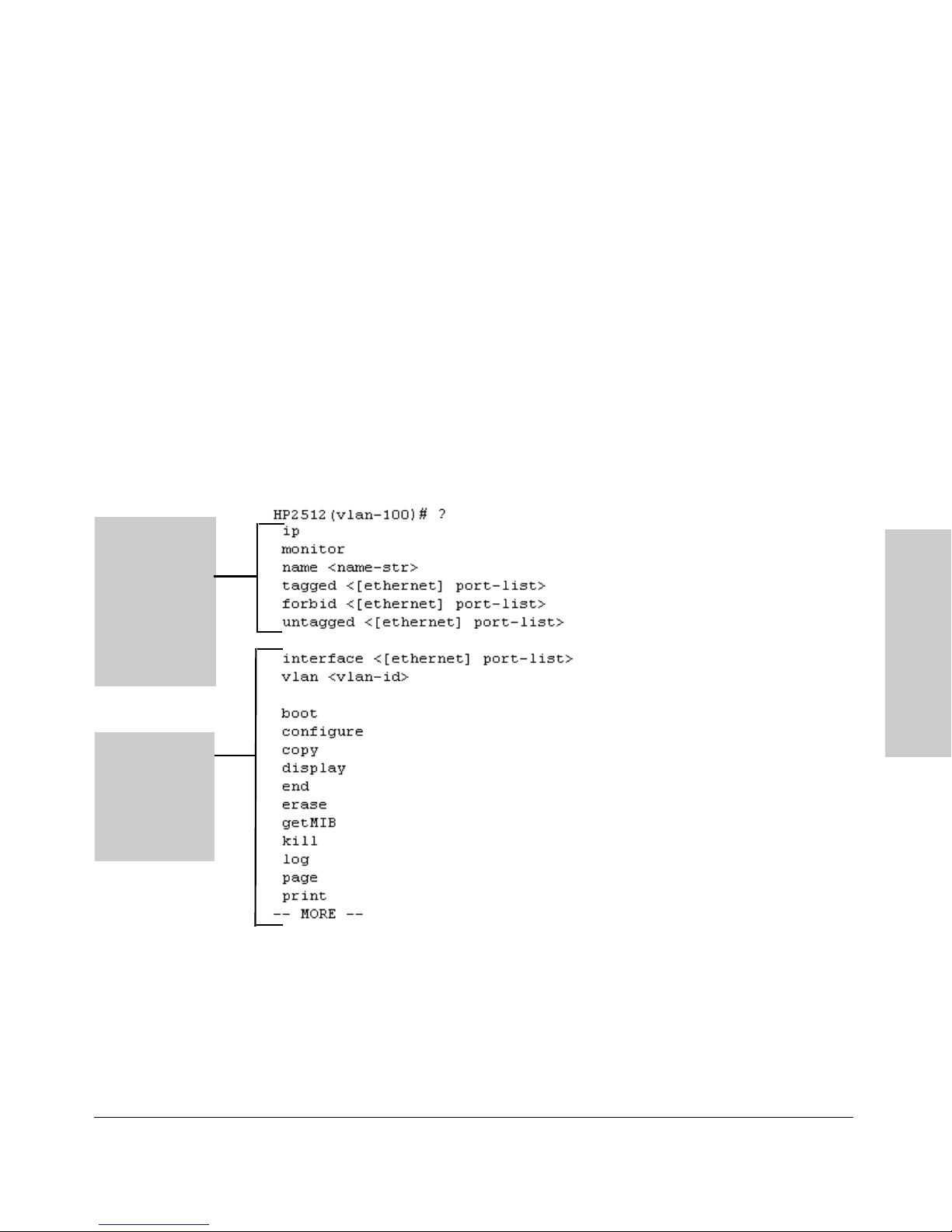
In the VLAN
context, the
first block of
commands in
the "?" listing
show the
commands that
will affect only
vlan-100.
Using the Command Line Interface (CLI)
Using the CLI
VLAN Context . Includes VLAN-specific commands that apply only to the
selected VLAN, plus Manager and Operator commands. The prompt for this
mode includes the VLAN ID of the selected VLAN. For example, if you had
already configured a VLAN with an ID of 100 in the switch:
HP2512(config)# vlan 100 Command executed at configura-
tion level to enter VLAN 100
context.
HP2512(vlan-100)# Resulting prompt showing VLAN
100 context.
HP2512(vlan-100)# ? Lists commands you can use in the
VLAN context, plus Manager, Operator, and context commands you
can execute at this level.
Using the Command Line
Interface (CLI)
The remaining
commands in
the listing are
Manager,
Operator, and
context
commands.
Figure 3-11. Context-Specific Commands Affecting VLAN Context
3-15
Page 58

Using the Command Line Interface (CLI)
CLI Control and Editing
CLI Control and Editing
Keystrokes Function
[Ctrl] [A] Jumps to the first character of the command line.
[Ctrl] [B] or [<]
[Ctrl] [C] Terminates a task and displays the command prompt.
[Ctrl] [D] Deletes the character at the cursor.
[Ctrl] [E] Jumps to the end of the current command line.
[Ctrl] [F] or [>]
[Ctrl] [K] Deletes from the cursor to the end of the command line.
[Ctrl] [L] or [Ctrl] [R]
[Ctrl] [N] or [v]
[Ctrl] [P] or [^]
[Ctrl] [U] or [Ctrl] [X]
Interface (CLI)
Using the Command Line
[Ctrl] [W] Deletes the last word typed.
[Esc] [B] Moves the cursor backward one word.
[Esc] [D] Deletes from the cursor to the end of the word.
[Esc] [F] Moves the cursor forward one word.
Moves the cursor back one character.
Moves the cursor forward one character.
Repeats current command line on a new line.
Enters the next command line in the history buffer.
Enters the previous command line in the history buffer.
Deletes from the cursor tothe beginning of the command line.
[Delete] or [Backspace]
3-16
Deletes the first character to the left of the cursor in the command
line.
Page 59

Using the HP Web Browser Interface
Chapter Contents
Overview . . . . . . . . . . . . . . . . . . . . . . . . . . . . . . . . . . . . . . . . . . . . . . . . . . . . . . . . 2
General Features . . . . . . . . . . . . . . . . . . . . . . . . . . . . . . . . . . . . . . . . . . . . . . . . . 3
Web Browser Interface Requirements . . . . . . . . . . . . . . . . . . . . . . . . . . . . . . . . 4
Starting an HP Web Browser Interface Session with the Switch . . . . . . . . . . 5
Using a Standalone Web Browser in a PC or UNIX Workstation . . . . . . 5
Using HP TopTools for Hubs & Switches . . . . . . . . . . . . . . . . . . . . . . . . . 6
Tasks for Your First HP Web Browser Interface Session . . . . . . . . . . . . . . . 8
Viewing the “First Time Install” Window . . . . . . . . . . . . . . . . . . . . . . . . . . 8
Creating Usernames and Passwords in the Browser Interface . . . . . . . 9
Using the Passwords . . . . . . . . . . . . . . . . . . . . . . . . . . . . . . . . . . . . . . 11
Using the User Names . . . . . . . . . . . . . . . . . . . . . . . . . . . . . . . . . . . . . 11
If You Lose a Password . . . . . . . . . . . . . . . . . . . . . . . . . . . . . . . . . . . . 11
Online Help for the HP Web Browser Interface . . . . . . . . . . . . . . . . . . . 12
4
Support/Mgmt URLs Feature . . . . . . . . . . . . . . . . . . . . . . . . . . . . . . . . . . . . . . 13
Support URL . . . . . . . . . . . . . . . . . . . . . . . . . . . . . . . . . . . . . . . . . . . . . . . . 14
Help and the Management Server URL . . . . . . . . . . . . . . . . . . . . . . . . . . 14
Providing Online Help . . . . . . . . . . . . . . . . . . . . . . . . . . . . . . . . . . 14
If Online Help Fails To Operate. . . . . . . . . . . . . . . . . . . . . . . . . . . 14
Policy Management and Configuration . . . . . . . . . . . . . . . . . . . . . 15
Status Reporting Features . . . . . . . . . . . . . . . . . . . . . . . . . . . . . . . . . . . . . . . . . 16
The Overview Window . . . . . . . . . . . . . . . . . . . . . . . . . . . . . . . . . . . . . . . . 16
The Port Utilization and Status Displays . . . . . . . . . . . . . . . . . . . . . . . . . 17
Port Utilization . . . . . . . . . . . . . . . . . . . . . . . . . . . . . . . . . . . . . . . . . . 17
Utilization Guideline . . . . . . . . . . . . . . . . . . . . . . . . . . . . . . . . . . . . 18
To change the amount of bandwidth the Port Utilization
bar graph shows . . . . . . . . . . . . . . . . . . . . . . . . . . . . . . . . . . . . . . 18
To display values for each graph bar. . . . . . . . . . . . . . . . . . . . . . . . 18
Port Status . . . . . . . . . . . . . . . . . . . . . . . . . . . . . . . . . . . . . . . . . . . . . . . 19
The Alert Log . . . . . . . . . . . . . . . . . . . . . . . . . . . . . . . . . . . . . . . . . . . . . . . . 20
Sorting the Alert Log Entries . . . . . . . . . . . . . . . . . . . . . . . . . . . . . . . 20
Alert Types . . . . . . . . . . . . . . . . . . . . . . . . . . . . . . . . . . . . . . . . . . . . . . 21
Viewing Detail Views of Alert Log Entries . . . . . . . . . . . . . . . . . . . . 22
The Status Bar . . . . . . . . . . . . . . . . . . . . . . . . . . . . . . . . . . . . . . . . . . . . . . . 23
Setting Fault Detection Policy . . . . . . . . . . . . . . . . . . . . . . . . . . . . . . . . . . 24
Using the HP Web Browser
Interface
4-1
Page 60

Using the HP Web Browser Interface
Overview
Overview
The HP web browser interface built into the switch lets you easily access the
switch from a browser-based PC on your network. This lets you do the
following:
■ Optimize your network uptime by using the Alert Log and other diagnostic
tools
■ Make configuration changes to the switch
■ Maintain security by configuring usernames and passwords
This chapter covers the following:
■ General features (page 4-3).
■ System requirements for using the web browser interface (page 4-4)
■ Starting a web browser interface session (page 4-5)
■ Tasks for your first web browser interface session (page 4-8):
• Creating usernames and passwords in the web browser interface
(page 4-9)
• Selecting the fault detection configuration for the Alert Log operation
(page 4-24)
• Getting access to online help for the web browser interface (page
4-12)
■ Description of the web browser interface:
• Overview window and tabs (page 4-16)
• Port Utilization and Status displays (page 4-17)
Interface
• Alert Log and Alert types (page 4-20)
• Setting the Fault Detection Policy (page 4-24)
Using the HP Web Browser
Note If you want security beyond that achieved with user names and passwords,
you can disable access to the web browser interface. This is done by either
executing no web-management at the Command Prompt or changing the Web
Agent Enabled parameter setting to No (page 5-22) .
4-2
Page 61

Using the HP Web Browser Interface
General Features
General Features
The Series 2500 switches include these web browser interface features:
Switch Configuration:
• Ports
• VLANs and Primary VLAN
• Fault detection
• Port monitoring (mirroring)
• System information
• Enable/Disable Multicast Filtering (IGMP) and Spanning Tree
• IP
• Stacking
• Support and management URLs
Switch Security:
• Passwords
• Authorized IP Managers
• Port security and Intrusion Log
Switch Diagnostics:
• Ping/Link Test
• Device reset
• Configuration report
Switch status
• Port utilization
• Port counters
• Port status
• Alert log
Switch system information listing
Using the HP Web Browser
Interface
4-3
Page 62

Using the HP Web Browser Interface
Web Browser Interface Requirements
Web Browser Interface Requirements
You can use equipment meeting the following requirements to access the web
browser interface on your intranet.
Table 4-1. System Requirements for Accessing the HP Web Browser Interface
Platform Entity and OS Version Minimum Recommended
PC Platform 90 MHz Pentium 120 MHz Pentium
HP-UX Platform (9.x or 10.x) 100 MHz 120 MHz
RAM 16 Mbytes 32 Mbytes
Screen Resolution 800 X 600 1,024 x 768
Color Count 256 65,536
Internet Browser
(English-language browser only)
PC Operating System Microsoft Windows® 95 and Windows NT
UNIX® Operating System Standard UNIX® OS
HP TopTools for Hubs & Switches
(Optional)
PCs:
• Netscape®
Communicator 4.x
• Microsoft® Internet
Explorer 4.x
UNIX: Netscape Navigator
4.5 or later
For the HP ProCurve Switch 2512 and 2524, use
product HP J2569R or later.
PCs:
• Netscape
Communicator 4. 5 or
later
• Microsoft® Internet
Explorer 5.0 or later
UNIX: Netscape
Navigator 4.5 or later
Interface
Using the HP Web Browser
4-4
Page 63

Using the HP Web Browser Interface
Starting an HP Web Browser Interface Session with the Switch
Starting an HP Web Browser Interface
Session with the Switch
You can start a web browser session in the following ways:
■ Using a standalone web browser on a network connection from a PC or
UNIX workstation:
• Directly connected to your network
• Connected through remote access to your network
■ Using a management station running HP TopTools for Hubs & Switches
on your network
Using a Standalone Web Browser in a PC or UNIX
Workstation
This procedure assumes that you have a supported web browser (page 4-4)
installed on your PC or workstation, and that an IP address has been configured on the switch. (For more on assigning an IP address, refer to "IP
Configuration" on page 5-3.)
TM
1. Make sure the Java
not, do one of the following:
• In Netscape 4.03, click on E
Enable Java and Enable JavaScript options.
• In Microsoft Internet Explorer 4.x, click on View, Internet O
Security, C
to the online Help for specific information on enabling the Java
applets.
ustom, [Settings] and scroll to the Java Permissions. Then refer
applets are enabled for your browser. If they are
dit, Preferences..., Advanced, then select
ptions,
Using the HP Web Browser
Interface
4-5
Page 64

Using the HP Web Browser Interface
Starting an HP Web Browser Interface Session with the Switch
2. Type the IP address (or DNS name) of the switch in the browser Location
or Address field and press [Enter]. (It is not necessary to include
http://.)
switch2512 [Enter] (example of a DNS-type name)
10.11.12.195 [Enter] (example of an IP address)
If you are using a Domain Name Server (DNS), your device may have a
name associated with it (for example, switch2512) that you can type in the
Location or Address field instead of the IP address. Using DNS names
typically improves browser performance. See your network administrator
for any name associated with the switch.
Using HP TopTools for Hubs & Switches
HP TopTools for Hubs & Switches is designed for installation on a network
management workstation. For this reason, the HP TopTools system requirements are different from the system requirements for accessing the switch’s
web browser interface from a non-management PC or workstation. For HP
TopTools requirements, refer to the information provided with HP TopTools
for Hubs & Switches.
This procedure assumes that:
■ You have installed the recommended web browser on a PC or workstation
that serves as your network management station.
■ The networked device you want to access has been assigned an IP address
and (optionally) a DNS name and has been discovered by HP TopTools
for Hubs & Switches. (For more on assigning an IP address, refer to "IP
Configuration" on page 5-3.)
Interface
To establish a web browser session with HP TopTools running, do the
following on the network management station:
TM
1. Make sure the Java
Using the HP Web Browser
are not, refer to the web browser online Help for specific information on
applets are enabled for your web browser. If they
enabling the Java applets.
2. Do one of the following tasks:
• On the HP TopTools Maps view, double-click on the symbol for the
networking device that you want to access.
• In HP TopTools, in the Topology Information dialog box, in the device
list, double-click on the entry for the device you want to access (IP
address or DNS name).
4-6
Page 65
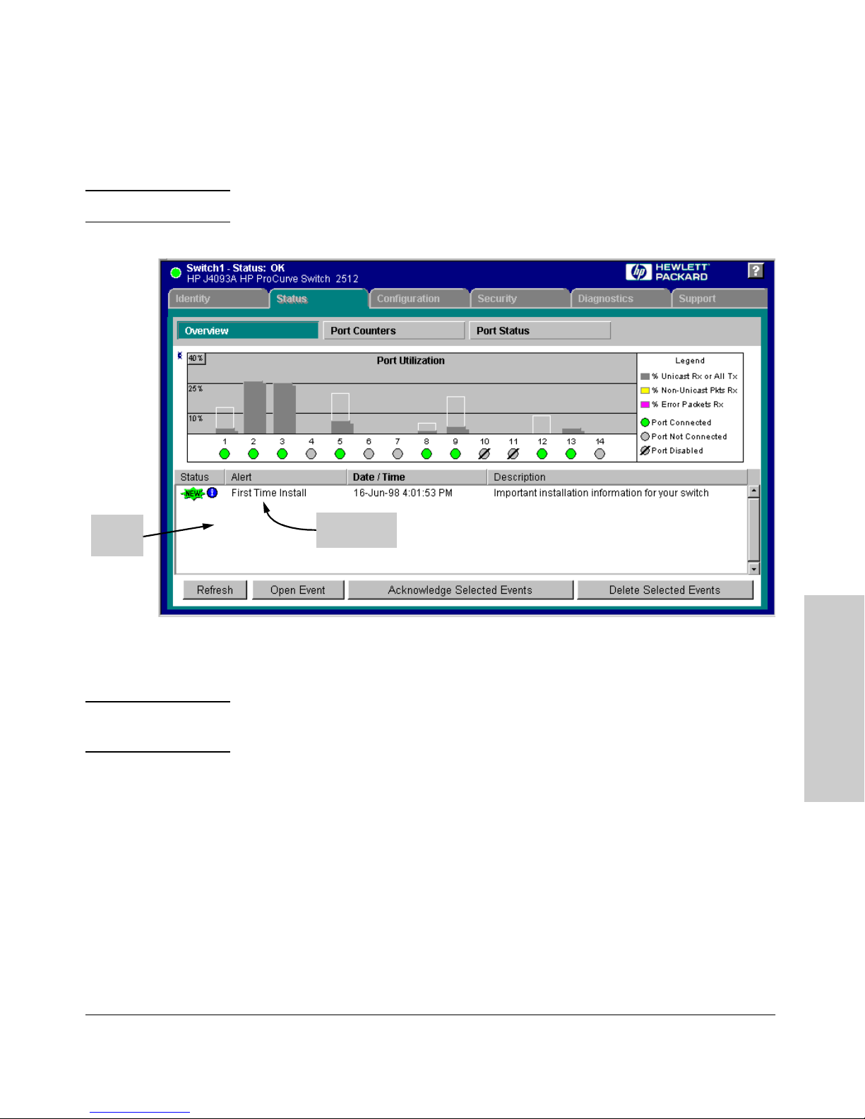
Using the HP Web Browser Interface
Starting an HP Web Browser Interface Session with the Switch
3. The web browser interface automatically starts with the Status Overview
window displayed for the selected device, as shown in figure 4-1.
Note If the Registration window appears, click on the Status tab.
Alert
Log
First-Time
Install Alert
Figure 4-1. Example of Status Overview Screen
Note The above screen appears somewhat different if the switch is configured as a
stack Commander. For an example, see figure 1-3 on page 1-5.
Using the HP Web Browser
Interface
4-7
Page 66
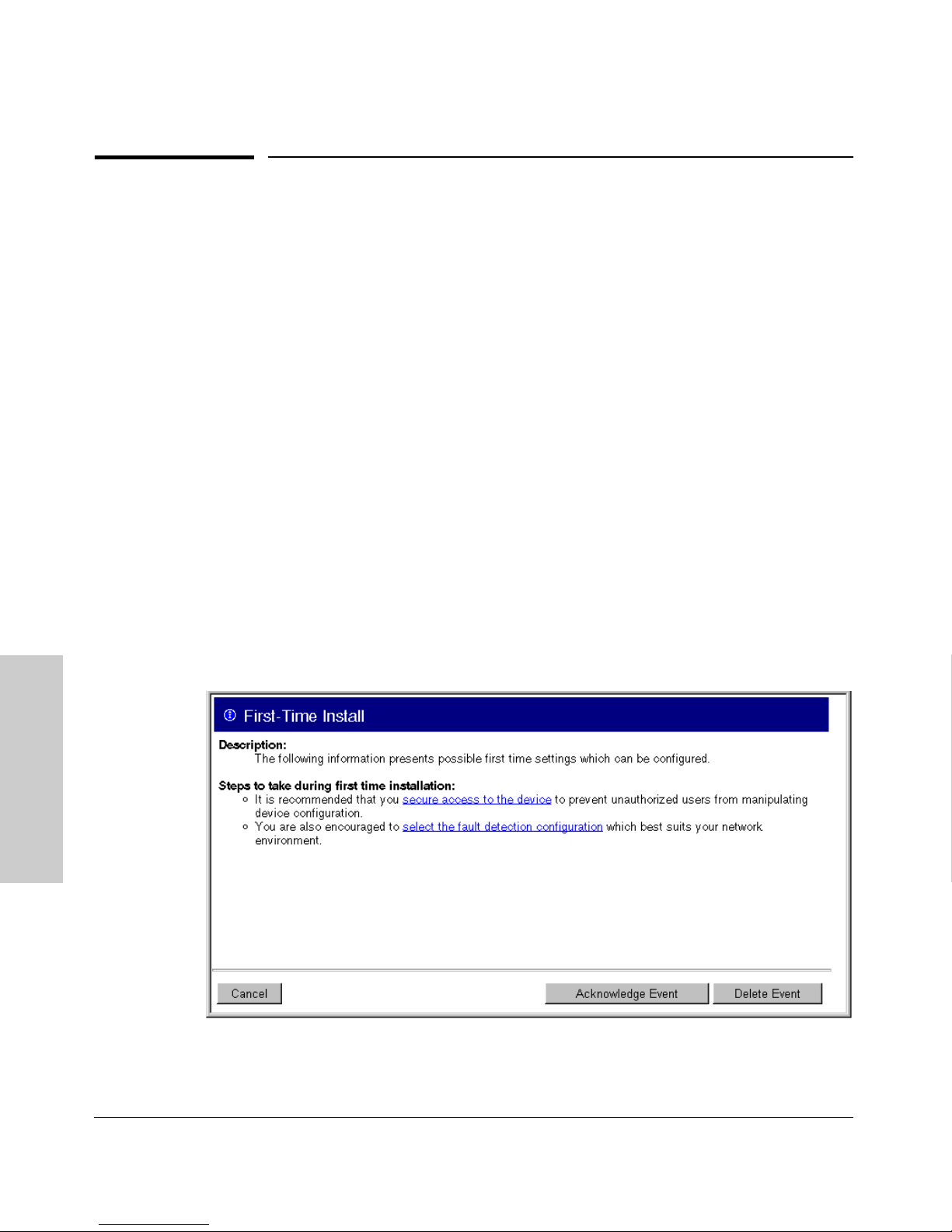
Using the HP Web Browser Interface
Tasks for Your First HP Web Browser Interface Session
Tasks for Your First HP Web Browser
Interface Session
The first time you access the web browser interface, there are three tasks that
you should perform:
■ Review the “First Time Install” window
■ Set Manager and Operator passwords
■ Set access to the web browser interface online help
Viewing the “First Time Install” Window
When you access the switch’s web browser interface for the first time, the
Alert log contains a “First Time Install” alert, as shown in figure 4-2. This gives
you information about first time installations, and provides an immediate
opportunity to set passwords for security and to specify a Fault Detection
policy, which determines the types of messages that will be displayed in the
Alert Log.
Double click on First Time Install in the Alert log (figure 4-1 on page 4-7). The
web browser interface then displays the “First Time Install” window, below.
Interface
Using the HP Web Browser
Figure 4-2. First-Time Install Window
4-8
Page 67

Using the HP Web Browser Interface
Tasks for Your First HP Web Browser Interface Session
This window is the launching point for the basic configuration you need to
perform to set web browser interface passwords to maintain security and
Fault Detection policy, which determines the types of messages that will be
displayed in the Alert Log.
To set web browser interface passwords, click on secure access to the device
to display the Device Passwords screen, and then go to the next page. (You
can also access the password screen by clicking on the Security tab.)
To set Fault Detection policy, click on select the fault detection configuration in
the second bullet in the window and go to the section, “Setting Fault Detection
Policy” on page 4-24. (You can also access the password screen by clicking on
the Configuration tab, and then [Fault Detection] button.)
Creating Usernames and Passwords in the Browser
Interface
You may want to create both a username and password to create access
security for your switch. There are two levels of access to the interface that
can be controlled by setting user names and passwords:
■ Operator. An Operator-level user name and password allows read-only
access to most of the web browser interface, but prevents access to the
Security window.
■ Manager. A Manager-level user name and password allows full read/
write access to the web browser interface.
Using the HP Web Browser
4-9
Interface
Page 68
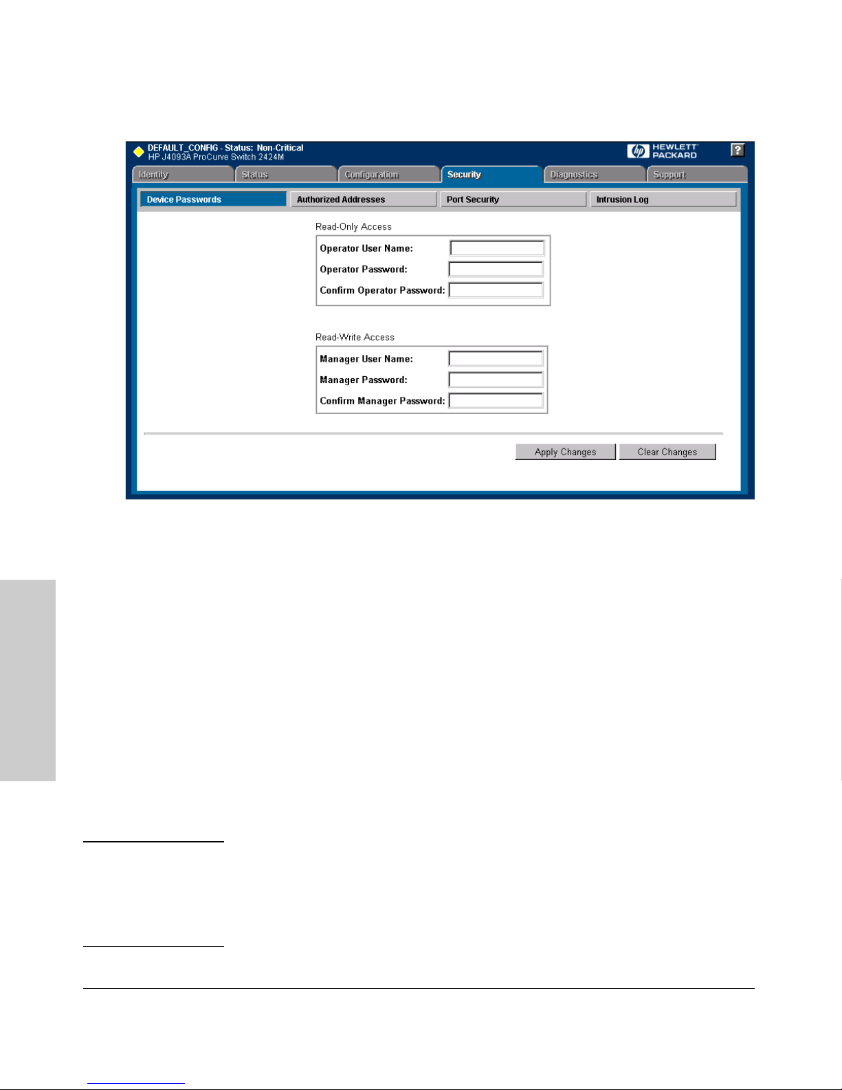
Using the HP Web Browser Interface
Tasks for Your First HP Web Browser Interface Session
Figure 4-3. The Device Passwords Window
To set the passwords:
1. Access the Device Passwords screen by one of the following methods:
• If the Alert Log includes a “First Time Install” event entry, double
click on this event, then, in the resulting display, click on the
secure access to the device link.
• Select the Security tab.
Interface
2. Click in the appropriate box in the Device Passwords window and enter
user names and passwords. You will be required to repeat the password
strings in the confirmation boxes.
Using the HP Web Browser
Both the user names and passwords can be up to 16 printable ASCII
characters.
3. Click on [Apply Changes] to activate the user names and passwords.
Note Passwords you assign in the web browser interface will overwrite previous
passwords assigned in either the web browser interface, the Command
Prompt, or the switch console. That is, the most recently assigned passwords
are the switch’s passwords, regardless of which interface was used to assign
the string.
4-10
Page 69
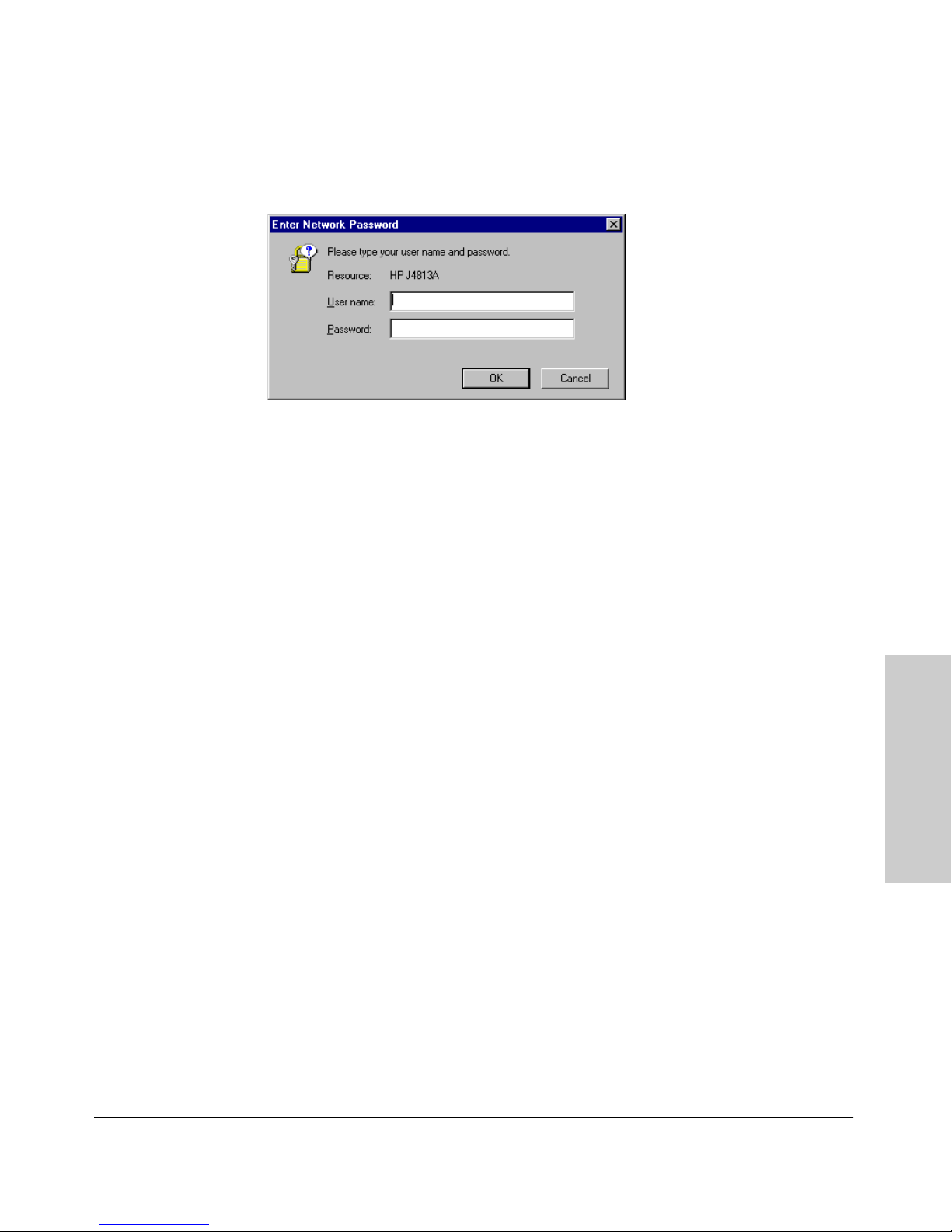
Using the HP Web Browser Interface
Tasks for Your First HP Web Browser Interface Session
Using the Passwords
Figure 4-4. Example of the Password Window in the Web Browser Interface
The manager and operator passwords are used to control access to all switch
interfaces. Once set, you will be prompted to supply the password every time
you try to access the switch through any of its interfaces. The password you
enter determines the capability you have during that session:
■ Entering the manager password gives you full read/write capabilities
■ Entering the operator password gives you read and limited write capabil-
ities.
Using the User Names
If you also set user names in the web browser interface screen, you must
supply the correct user name for web browser interface access. If a user name
has not been set, then leave the User Name field in the password window
blank.
Note that the Command Prompt and switch console interfaces use only the
password, and do not prompt you for the User Name.
If You Lose a Password
If you lose the passwords, you can clear them by pressing the Clear button on
the front of the switch. This action deletes all password and user name
protection from all of the switch’s interfaces.
The Clear button is provided for your convenience, but its presence means
that if you are concerned with the security of the switch configuration and
operation, you should make sure the switch is installed in a secure location,
such as a locked wiring closet.
Using the HP Web Browser
Interface
4-11
Page 70
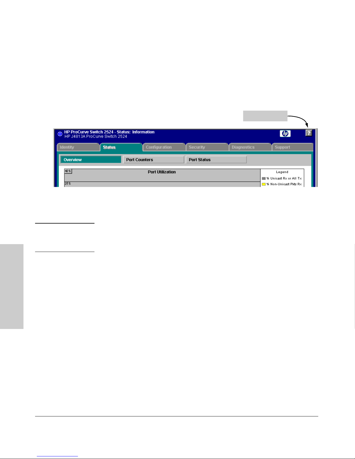
Using the HP Web Browser Interface
Tasks for Your First HP Web Browser Interface Session
Online Help for the HP Web Browser Interface
Online Help is available for the web browser interface. You can use it by
clicking on the question mark button in the upper right corner of any of the
web browser interface screens.
Figure 4-5. The Help Button
The Help Button
Context-sensitive help is provided for the screen you are on.
Note If you do not have HP TopTools for Hubs and Switches installed on your
network and do not have an active connection to the World Wide Web, then
Online help for the web browser interface will not be available.
For more on Help access and operation, refer to “Help and the Management
Server URL” on page 4-14.
Interface
Using the HP Web Browser
4-12
Page 71
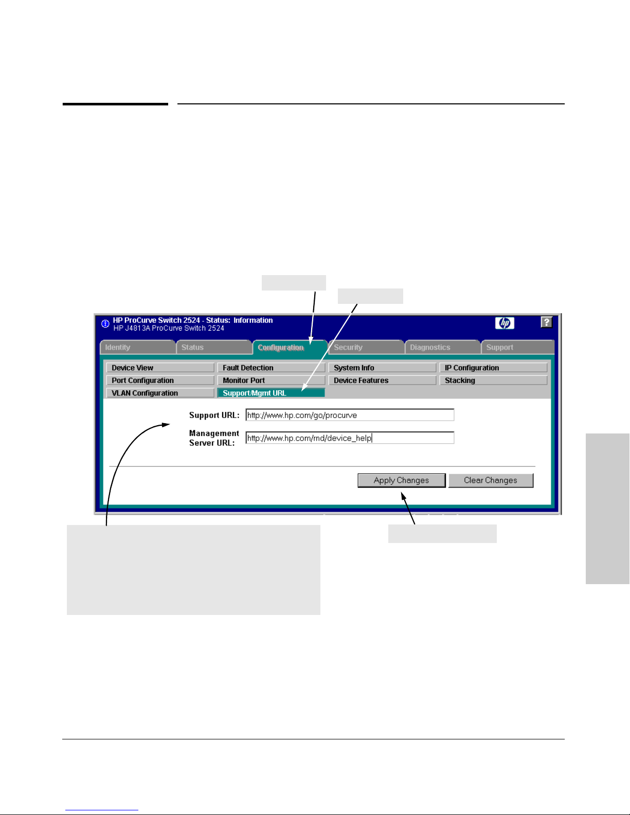
Using the HP Web Browser Interface
Support/Mgmt URLs Feature
Support/Mgmt URLs Feature
The Support/Mgmt URLs window enables you to change the World Wide Web
Universal Resource Locator (URL) for two functions:
■ Support URL – a support information site for your switch
■ Management Server URL – the site for online help for the web browser
interface, and, if set up, the URL of a network management station running
HP TopTools for Hubs & Switches.
1. Click Here
2. Click Here
3. Enter URLs for:
- the support information source you want the switch to access
when you click on the web browser interface Support tab – the
default is HP’s ProCurve network products World Wide Web
home page
- the URL of the network Management server or other
source of the online help files for this web browser inter face. (The default accesses Help on HP’s World Wide Web site.)
Figure 4-6. The Default Support/Mgmt URLs Window
Using the HP Web Browser
Interface
4. Click on Apply Changes
4-13
Page 72

Using the HP Web Browser Interface
Support/Mgmt URLs Feature
Support URL
This is the site that the switch accesses when you click on the Support tab on
the web browser interface. The default URL is:
http://www.hp.com/go/procurve
which is the World Wide Web site for Hewlett-Packard’s networking products.
Click on the [Support] button on that page and you can get to support information
regarding your switch, including white papers, operating system (OS) updates,
and more.
You could instead enter the URL for a local site that you use for entering
reports about network performance, or whatever other function you would
like to be able to easily access by clicking on the [Support] tab.
Help and the Management Server URL
This field specifies which of the following two locations the switch will use to
find online Help for the web browser interface:
■ The URL of online Help provided by HP on the world wide web
■ The URL of a network management station running HP TopTools for Hubs
& Switches
Providing Online Help. The Help files are automatically available if you
install HP TopTools for Hubs & Switches on your network or if you already
have Internet access to the World Wide Web. (The Help files are included with
HP TopTools for Hubs & Switches, and are also automatically available from
HP via the World Wide Web.)
Interface
Retrieval of the Help files is controlled by automatic entries to the Management
Server URL field on the Configuration / Support/Mgmt URLs screen, shown in
figure 4-6. The switch is shipped with the URL set to retrieve online Help from
Using the HP Web Browser
the HP World Wide Web site. However, if HP TopTools for Hubs & Switches is
installed on a management station on your network and discovers the switch,
the Management Server URL is automatically changed to retrieve the Help
from your TopTools management station.
If Online Help Fails To Operate. Do one of the following:
■ If HP TopTools for Hubs & Switches is installed and running on your
network, enter the IP address or DNS name of the network management
station in the Management Server URL field shown in figure 4-7 on page
4-15.
4-14
Page 73
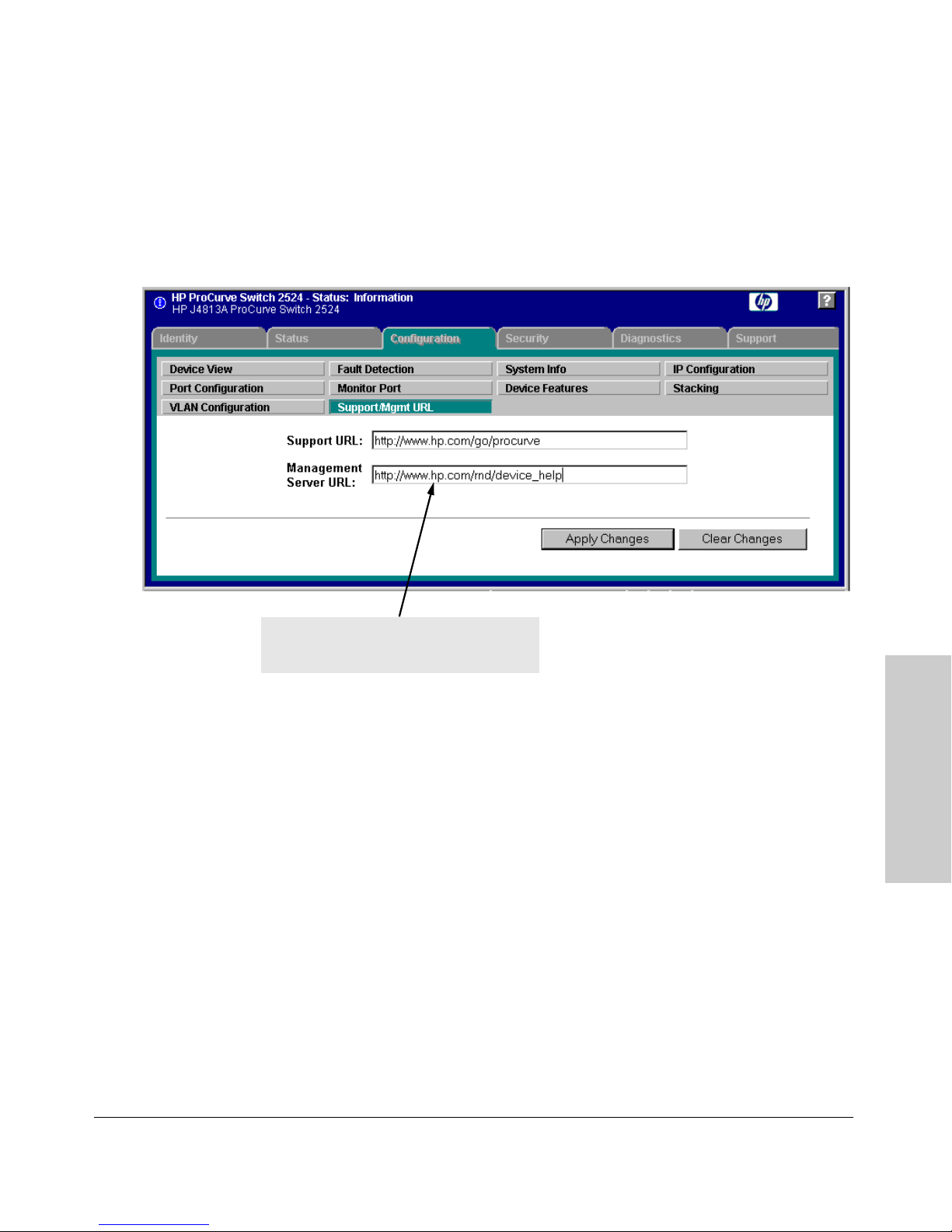
Using the HP Web Browser Interface
Support/Mgmt URLs Feature
■ If you have World Wide Web access from your PC or workstation, and do
not have HP TopTools installed on your network, enter the following URL
in the Management Server URL field shown in figure 4-7 on page 4-15:
http://www.hp.com/rnd/device_help
Enter IP address of HP TopTools network
management station, or URL of location of
help files on HP’s World Wide Web site here.
Figure 4-7. How To Access Web Browser Interface Online Help
Policy Management and Configuration. HP Top Tools for Hubs &
Switches can perform network-wide policy management and configuration of
your switch. The Management Server URL field identifies the management
station that is performing that function. For more information, refer to the
documentation provided on the HP TopTools for Hubs & Switches CD shipped
with the switch.
Using the HP Web Browser
Interface
4-15
Page 74

Using the HP Web Browser Interface
Status Reporting Features
Status Reporting Features
Browser elements covered in this section include:
■ The Overview window (below)
■ Port utilization and status (page )
■ The Alert log (page )
■ The Status bar (page )
The Overview Window
The Overview Window is the home screen for any entry into the web browser
interface.The following figure identifies the various parts of the screen.
Status Bar
(page 4-23)
Tab Bar
Button Bar
Port Utilization Graphs
(page 4-17)
Port Status
Indicators
(page 4-19)
Active Button
Active Tab
Interface
Alert Log
(page 4-20)
Using the HP Web Browser
Alert Log
Control Bar
Figure 4-8. The Overview Window
4-16
Page 75
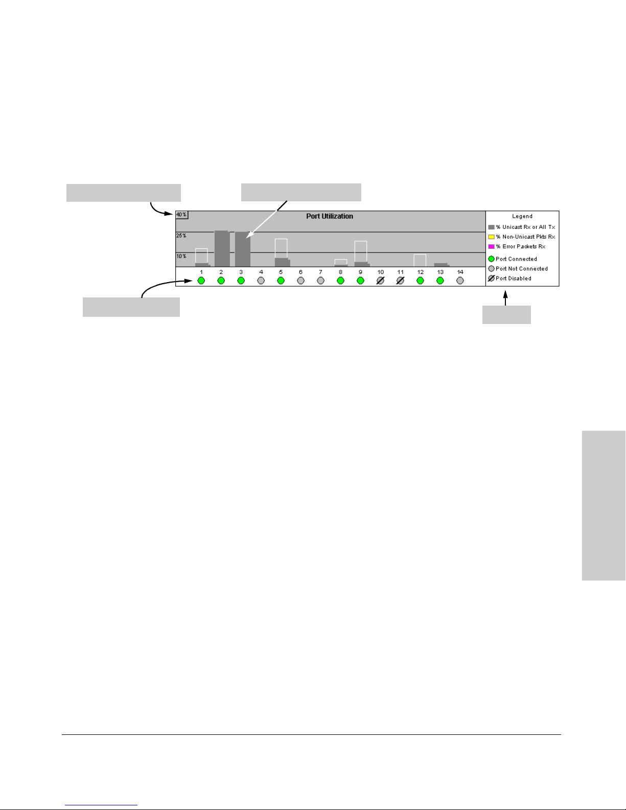
Using the HP Web Browser Interface
Status Reporting Features
The Port Utilization and Status Displays
The Port Utilization and Status displays show an overview of the status of the
switch and the amount of network activity on each port. The following figure
shows a sample reading of the Port Utilization and Port Status.
Bandwidth Display Control
Port Status Indicators
Port Utilization Bar Graphs
Legend
Figure 4-9. The Graphs Area
Port Utilization
The Port Utilization bar graphs show the network traffic on the port with a
breakdown of the packet types that have been detected (unicast packets, nonunicast packets, and error packets). The Legend identifies traffic types and
their associated colors on the bar graph:
■ % Unicast Rx & All Tx: This is all unicast traffic received and all
transmitted traffic of any type. This indicator (a blue color on many
systems) can signify either transmitted or received traffic.
■ % Non-Unicast Pkts Rx: All multicast and broadcast traffic received by
the port. This indicator (a gold color on many systems) enables you to
know “at-a-glance” the source of any non-unicast traffic that is causing
high utilization of the switch. For example, if one port is receiving heavy
broadcast or multicast traffic, all ports will become highly utilized. By
color-coding the received broadcast and multicast utilization, the bar
graph quickly and easily identifies the offending port. This makes it faster
and easier to discover the exact source of the heavy traffic because you
don’t have to examine port counter data from several ports.
■ % Error Pkts Rx: All error packets received by the port. (This indicator
is a reddish color on many systems.) Although errors received on a port
are not propagated to the rest of the network, a consistently high number
of errors on a specific port may indicate a problem on the device or
network segment connected to the indicated port.
Using the HP Web Browser
Interface
4-17
Page 76
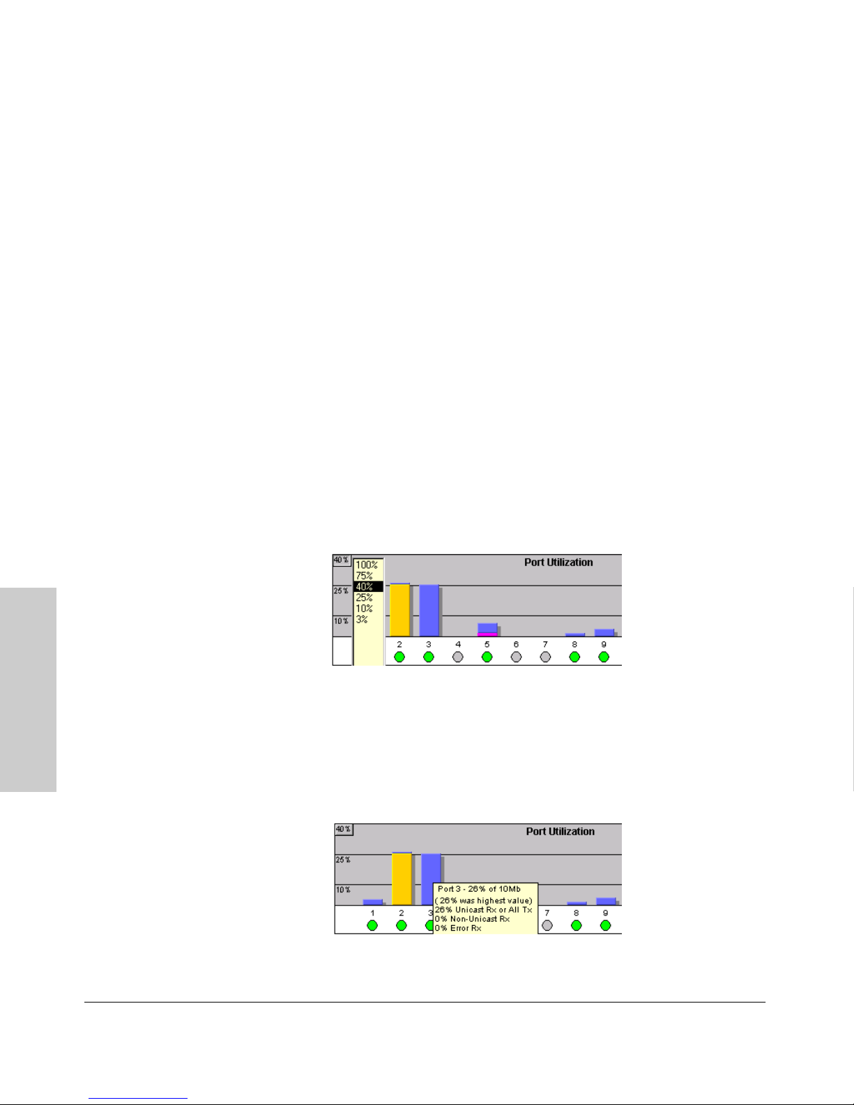
Using the HP Web Browser Interface
Status Reporting Features
■ Maximum Activity Indicator: As the bars in the graph area change
height to reflect the level of network activity on the corresponding port,
they leave an outline to identify the maximum activity level that has been
observed on the port.
Utilization Guideline. A network utilization of 40% is considered the
maximum that a typical Ethernet-type network can experience before encountering performance difficulties. If you observe utilization that is consistently
higher than 40% on any port, click on the Port Counters button to get a detailed
set of counters for the port.
To change the amount of bandwidth the Port Utilization bar graph
shows. Click on the bandwidth display control button in the upper left corner
of the graph. (The button shows the current scale setting, such as 40%.) In the
resulting menu, select the bandwidth scale you want the graph to show (3%,
10%, 25%, 40%, 75%, or 100%), as shown in figure 3-7.
Note that when viewing activity on a gigabit port, you may want to select a
lower value (such as 3% or 10%). This is because the bandwidth utilization of
current network applications on gigabit links is typically minimal, and may
not appear on the graph if the scale is set to show high bandwidth utilization.
Figure 4-10. Changing the Graph Area Scale
Interface
To display values for each graph bar. Hold the mouse cursor over any of
the bars in the graph, and a pop-up display is activated showing the port
Using the HP Web Browser
identification and numerical values for each of the sections of the bar, as
shown in figure 4-11 (next).
Figure 4-11. Display of Numerical Values for the Bar
4-18
Page 77
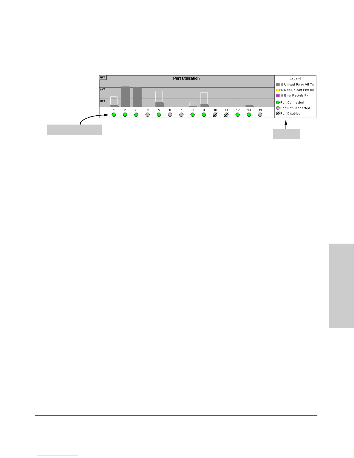
Port Status
Using the HP Web Browser Interface
Status Reporting Features
Port Status Indicators
Legend
Figure 4-12. The Port Status Indicators and Legend
The Port Status indicators show a symbol for each port that indicates the
general status of the port. There are four possible statuses:
■ Port Connected – the port is enabled and is properly connected to an
active network device.
■ Port Not Connected – the port is enabled but is not connected to an
active network device. A cable may not be connected to the port, or the
device at the other end may be powered off or inoperable, or the cable or
connected device could be faulty.
■ Port Disabled – the port has been configured as disabled through the
web browser interface, the switch console, or SNMP network management.
■ Port Fault-Disabled – a fault condition has occurred on the port that
has caused it to be auto-disabled. Note that the Port Fault-Disabled
symbol will be displayed in the legend only if one or more of the ports is
in that status. See chapter 7, “Monitoring and Analyzing Switch Operation”
for more information.
Using the HP Web Browser
Interface
4-19
Page 78
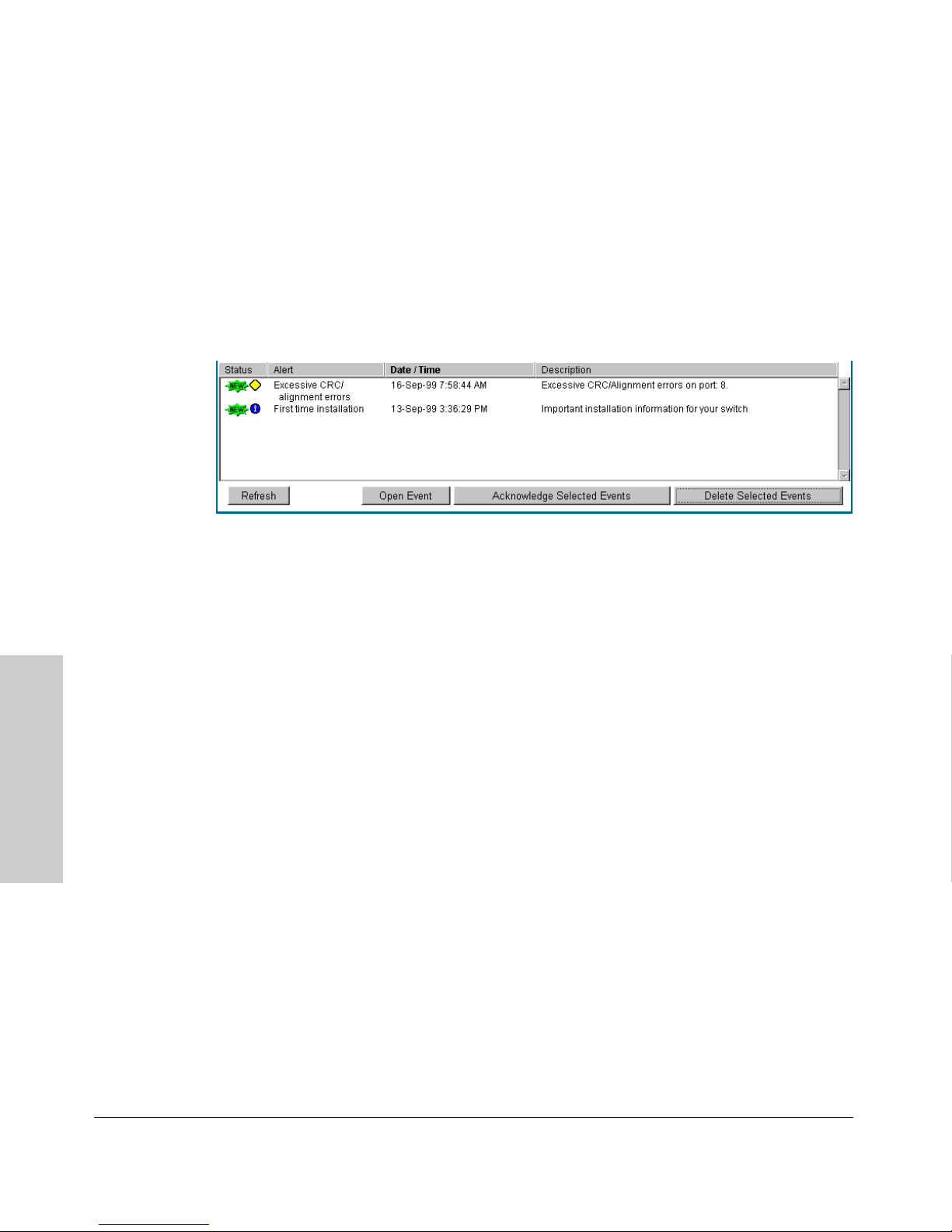
Using the HP Web Browser Interface
Status Reporting Features
The Alert Log
The web browser interface Alert Log, shown in the lower half of the screen,
shows a list of network occurrences, or alerts, that were detected by the
switch. Typical alerts are Broadcast Storm, indicating an excessive number of
broadcasts received on a port, and Problem Cable, indicating a faulty cable. A
full list of alerts is shown in the table on page 4-21.
Figure 4-13. Example of the Alert Log
Each alert has the following fields of information:
■ Status – The level of severity of the event generated. Severity levels can
be Information, Normal, Warning, and Critical. If the alert is new (has not
yet been acknowledged), the New symbol is also in the Status column.
■ Alert – The specific event identification.
■ Date/Time – The date and time the event was received by the web
browser interface. This value is shown in the format: DD-MM-YY
HH:MM:SS AM/PM, for example, 16-Sep-99 7:58:44 AM.
■ Description – A short narrative statement that describes the event. For
Interface
example, Excessive CRC/Alignment errors on port: 8.
Sorting the Alert Log Entries
Using the HP Web Browser
The alerts are sorted, by default, by the Date/Time field with the most recent
alert listed at the top of the list. The second most recent alert is displayed
below the top alert and so on. If alerts occurred at the same time, the
simultaneous alerts are sorted by order in which they appear in the MIB.
The alert field that is being used to sort the alert log is indicated by which
column heading is in bold. You can sort by any of the other columns by clicking
on the column heading. The Alert and Description columns are sorted alphabetically, while the Status column is sorted by severity type, with more critical
severity indicators appearing above less critical indicators.
4-20
Page 79
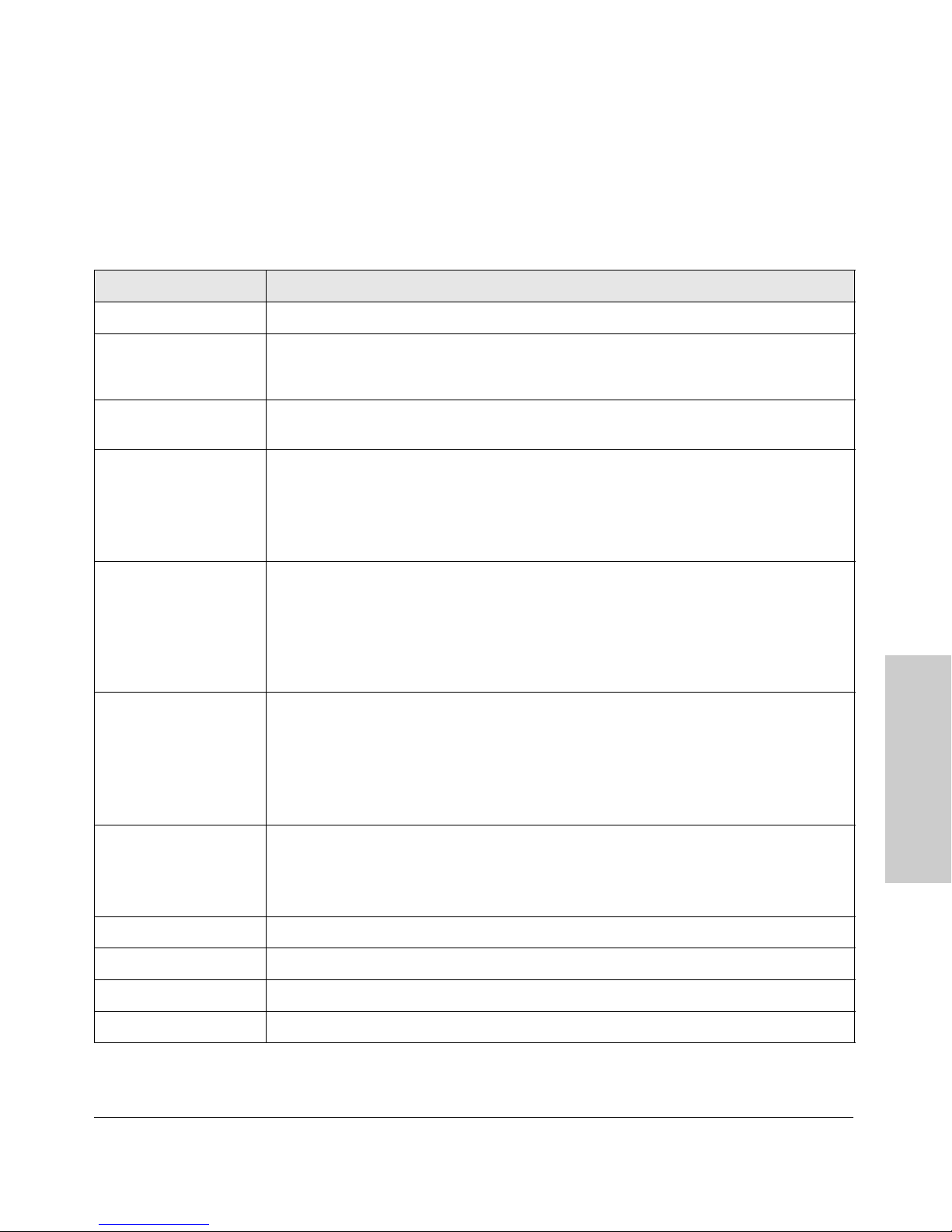
Alert Types
The following table lists the types of alerts that can be generated.
Table 4-2. Alert Strings and Descriptions
Alert String Alert Description
First Time Install Important installation information for your switch.
Using the HP Web Browser Interface
Status Reporting Features
Too many undersized/
giant packets
Excessive jabbering A device connected to this port is incessantly transmitting packets (“jabbering”), detected as
Excessive CRC/alignment
errors
Excessive late collisions Late collisions (collisions detected after transmitting 64 bytes) have been detected on this
High collision or drop rate A large number of collisions or packet drops have occurred on the port. Possible causes
A device connected to this port is transmitting packets shorter than 64 bytes or longer than
1518 bytes (longer than 1522 bytes if tagged), with valid CRCs (unlike runts, which have invalid
CRCs).
oversized packets with CRC errors.
A high percentage of data errors has been detected on this port. Possible causes include:
• Faulty cabling or invalid topology.
• Duplex mismatch (full-duplex configured on one end of the link, half-duplex configured on
the other)
• A malfunctioning NIC, NIC driver, or transceiver
port. Possible causes include:
• An overextended LAN topology
• Duplex mismatch (full-duplex configured on one end of the link, half-duplex configured on
the other)
• A misconfigured or faulty device connected to the port
include:
• A extremely high level of traffic on the port
• Duplex mismatch
• A misconfigured or malfunctioning NIC or transceiver on a device connected to this port
• A topology loop in the network
Using the HP Web Browser
Interface
Excessive broadcasts An extremely high percentage of broadcasts was received on this port. This degrades the
performance of all devices connected to the port. Possible causes include:
• A network topology loop—this is the usual cause
• A malfunctioning device, NIC, NIC driver, or software package
Network Loop Network loop has been detected by the switch.
Loss of Link Lost connection to one or multiple devices on the port.
Loss of stack member The Commander has lost the connection to a stack member.
Security violation A security violation has occurred.
4-21
Page 80
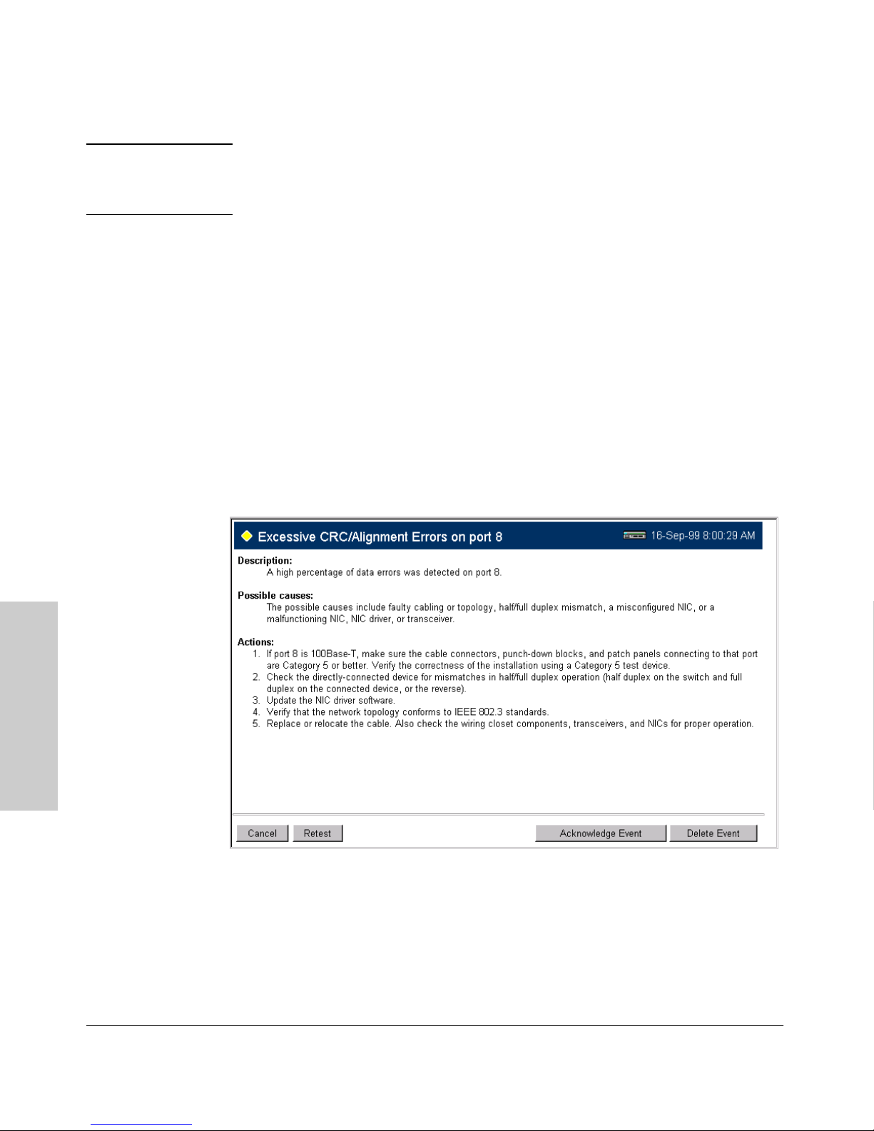
Using the HP Web Browser Interface
Status Reporting Features
Note When troubleshooting the sources of alerts, it may be helpful to check the
switch’s Port Status and Port Counter windows and the Event Log in the
console interface.
Viewing Detail Views of Alert Log Entries
By double clicking on Alert Entries, the web browser interface displays a
Detail View or separate window detailing information about the events. The
Detail View contains a description of the problem and a possible solution. It
also provides four management buttons:
■ Acknowledge Event – removes the New symbol from the log entry
■ Delete Event – removes the alert from the Alert Log
■ Cancel Button – closes the detail view with no change to the status of
the alert and returns you to the Overview screen.
A sample Detail View describing an Excessive CRC/Alignment Error alert is
shown here.
Interface
Using the HP Web Browser
Figure 4-14. Example of Alert Log Detail View
4-22
Page 81
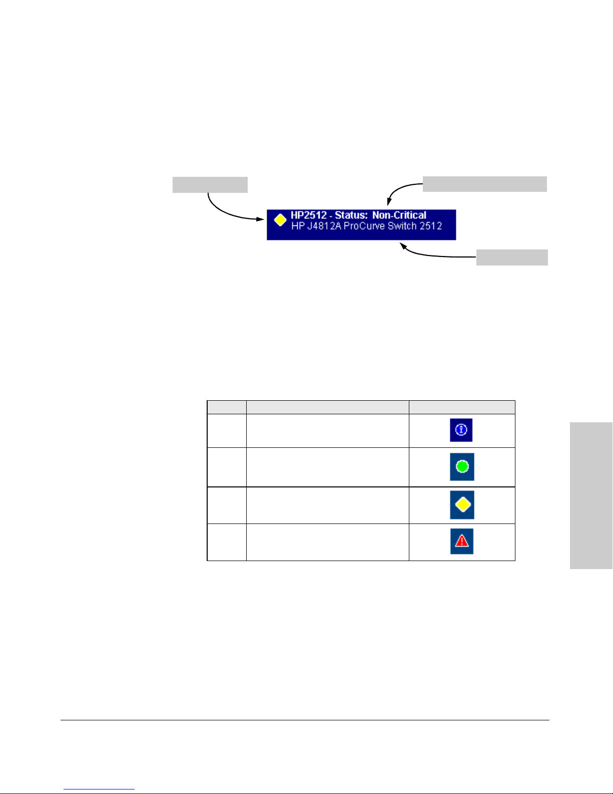
Using the HP Web Browser Interface
Status Reporting Features
The Status Bar
The Status Bar is displayed in the upper left corner of the web browser
interface screen. Figure 4-15 shows an expanded view of the status bar.
Status Indicator
Most Critical Alert Description
Product Name
Figure 4-15. Example of the Status Bar
The Status bar consists of four objects:
■ Status Indicator. Indicates, by icon, the severity of the most critical alert
in the current display of the Alert Log. This indicator can be one of three
shapes and colors as shown in the following table.
Table 4-3. Status Indicator Key
Color Switch Status Status Indicator Shape
Blue Normal Activity; "First time installation"
information available in the Alert log.
Green Normal Activity
Using the HP Web Browser
Interface
Yellow Warning
Red Critical
■ System Name. The name you have configured for the switch by using
Identity screen, system name command, or the switch console System
Information screen.
■ Most Critical Alert Description. A brief description of the earliest,
unacknowledged alert with the current highest severity in the Alert Log,
appearing in the right portion of the Status Bar. In instances where
multiple critical alerts have the same severity level, only the earliest
unacknowledged alert is deployed in the Status bar.
4-23
Page 82
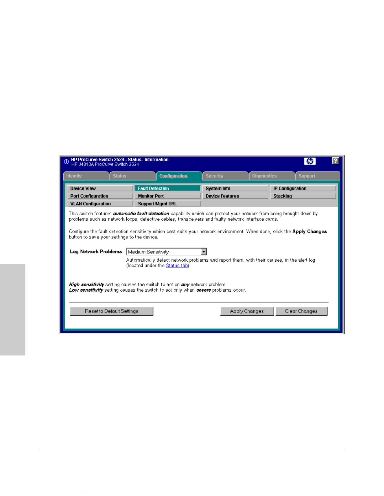
Using the HP Web Browser Interface
Status Reporting Features
■ Product Name. The product name of the switch to which you are
connected in the current web browser interface session.
Setting Fault Detection Policy
One of the powerful features in the web browser interface is the Fault
Detection facility. For your switch, this feature controls the types of alerts
reported to the Alert Log based on their level of severity.
Set this policy in the Fault Detection window (figure 4-16).
Interface
Figure 4-16. The Fault Detection Window
Using the HP Web Browser
The Fault Detection screen contains a list box for setting fault detection and
response policy. You set the sensitivity level at which a network problem
should generate an alert and send it to the Alert Log.
To provide the most information on network problems in the Alert Log, the
recommended sensitivity level for Log Network Problems is High Sensitivity. The
Fault Detection settings are:
4-24
Page 83

Using the HP Web Browser Interface
Status Reporting Features
■ High Sensitivity. This policy directs the switch to send all alerts to the
Alert Log. This setting is most effective on networks that have none or
few problems.
■ Medium Sensitivity. This policy directs the switch to send alerts related
to network problems to the Alert Log. If you want to be notified of
problems which cause a noticeable slowdown on the network, use this
setting.
■ Low Sensitivity. This policy directs the switch to send only the most
severe alerts to the Alert Log. This policy is most effective on a network
that normally has a lot of problems and you want to be informed of only
the most severe ones.
■ Never. Disables the Alert Log and transmission of alerts (traps) to the
management server (in cases where a network management tool such as
HP TopTools for Hubs & Switches is in use). Use this option when you
don’t want to use the Alert Log.
The Fault Detection Window also contains three Change Control Buttons:
■ Apply Changes. This button stores the settings you have selected for all
future sessions with the web browser interface until you decide to change
them.
■ Clear Changes. This button removes your settings and returns the
settings for the list box to the level it was at in the last saved detectionsetting session.
■ Reset to Default Settings. This button reverts the policy setting to
Medium Sensitivity for Log Network Problems.
Using the HP Web Browser
4-25
Interface
Page 84

Using the HP Web Browser Interface
Status Reporting Features
Interface
Using the HP Web Browser
4-26
Page 85

Configuring IP Addressing, Interface Access,
and System Information
Chapter Contents
Overview . . . . . . . . . . . . . . . . . . . . . . . . . . . . . . . . . . . . . . . . . . . . . . . . . . . . . 5-2
IP Configuration . . . . . . . . . . . . . . . . . . . . . . . . . . . . . . . . . . . . . . . . . . . . . 5-3
Just Want a Quick Start? . . . . . . . . . . . . . . . . . . . . . . . . . . . . . . . . . . . . 5-4
IP Addressing with Multiple VLANs . . . . . . . . . . . . . . . . . . . . . . . . . . . 5-4
IP Addressing in a Stacking Environment . . . . . . . . . . . . . . . . . . . . . . 5- 5
Menu: Configuring IP Address, Gateway, Time-To-Live (TTL),
and Timep . . . . . . . . . . . . . . . . . . . . . . . . . . . . . . . . . . . . . . . . . . . . . . . . . 5- 5
CLI: Configuring IP Address, Gateway, Time-To-Live (TTL),
and Timep . . . . . . . . . . . . . . . . . . . . . . . . . . . . . . . . . . . . . . . . . . . . . . . . . 5-7
Web: Configuring IP Addressing . . . . . . . . . . . . . . . . . . . . . . . . . . . . . 5-10
How IP Addressing Affects Switch Operation . . . . . . . . . . . . . . . . . . 5-10
DHCP/Bootp Operation . . . . . . . . . . . . . . . . . . . . . . . . . . . . . . . . . 5-11
Network Preparations for Configuring DHCP/Bootp . . . . . . . . 5-14
Globally Assigned IP Network Addresses . . . . . . . . . . . . . . . . . . . . . 5-15
5
Configuring IP Addressing,
Interface Access, and
Interface Access: Console/Serial Link, Web,
and Inbound Telnet . . . . . . . . . . . . . . . . . . . . . . . . . . . . . . . . . . . . . . . . . 5-16
Menu: Modifying the Interface Access . . . . . . . . . . . . . . . . . . . . . . . . 5-17
CLI: Modifying the Interface Access . . . . . . . . . . . . . . . . . . . . . . . . . . 5-18
System Information . . . . . . . . . . . . . . . . . . . . . . . . . . . . . . . . . . . . . . . . . 5-21
Menu: Viewing and Configuring System Information . . . . . . . . . . . . 5-22
CLI: Viewing and Configuring System Information . . . . . . . . . . . . . 5- 23
Web: Configuring System Parameters . . . . . . . . . . . . . . . . . . . . . . . . 5- 25
5-1
Page 86

Configuring IP Addressing, Interface Access, and System Information
Overview
Overview
This chapter describes the switch configuration features available in the menu
interface, CLI and web browser interface. For help on how to use these
interfaces, refer to:
■ Chapter 2, “Using the Menu Interface”
■ Chapter 3, “Using the Command Line Interface (CLI)”
■ Chapter 4, Using the HP Web Browser Interface”
Why Configure IP Addressing? In its factory default configuration, the
Interface Access, and
Configuring IP Addressing,
switch operates as a multiport learning bridge with network connectivity
provided by the ports on the switch. However, to enable specific management
access and control through your network, you will need IP addressing. (See
table 5-1 on page 5-11.)
Why Configure Interface Access and System Information? The interface access features in the switch operate properly by default. However, you
can modify or disable access features to suit your particular needs. Similarly,
you can choose to leave the system information parameters at their default
settings. However, using these features can help you to more easily manage a
group of devices across your network.
5-2
Page 87

Configuring IP Addressing, Interface Access, and System Information
IP Configuration
IP Configuration
IP Configuration Features
Feature Default Menu CLI Web
IP Address and Subnet Mask DHCP/Bootp page 5-5 page 5-7 page 5-10
Default Gateway Address none page 5-5 page 5-7 page 5-10
Packet Time-To-Live (TTL) 64 seconds page 5-5 page 5-7 n/a
Time Server (Timep) DHCP page 5-5 page 5-7 n/a
IP Address and Subnet Mask. Configuring the switch with an IP address
expands your ability to manage the switch and use its features. By default, the
switch is configured to automatically receive IP addressing on the default
VLAN from a DHCP/Bootp server that has been configured correctly with
information to support the switch. (Refer to “DHCP/Bootp Operation” on page
5-11 for information on setting up automatic configuration from a server.)
However, if you are not using a DHCP/Bootp server to configure IP addressing,
use the menu interface or the CLI to manually configure the initial IP values.
After you have network access to a device, you can use the web browser
interface to modify the initial IP configuration if needed.
Configuring IP Addressing,
Interface Access, and
For information on how IP addressing affects switch performance, refer to
“How IP Addressing Affects Switch Operation” on page 5-10.
Default Gateway Operation. The default gateway is required when a
router is needed for tasks such as reaching off-subnet destinations or forwarding traffic across multiple VLANs. The gateway value is the IP address of the
next-hop gateway node for the switch, which is used if the requested destination address is not on a local subnet/VLAN. If the switch does not have a
manually-configured default gateway and DHCP/Bootp is configured on the
primary VLAN, then the default gateway value provided by the DHCP or Bootp
server will be used. If the switch has a manually configured default gateway,
then the switch uses this gateway, even if a different gateway is received via
DHCP or Bootp on the primary VLAN. (This is also true for TimeP and a nondefault Time-To-Live and .) See “Notes” on page 5-4 and “Which VLAN Is
Primary?” on page 9-53.
Packet Time-To-Live (TTL) . This parameter specifies how long in seconds an outgoing packet should exist in the network. In most cases, the default
setting (64 seconds) is adequate.
5-3
Page 88

Configuring IP Addressing, Interface Access, and System Information
IP Configuration
Timep Operation. Use this optional parameter if you want the switch to get
its time information from another device operating as a Timep server. In its
default Timep configuration, the switch attempts to get a Timep server address
from a DHCP server. Other configuration options are to manually assign a
Timep server address or to disable the Timep server feature.
Just Want a Quick Start?
If you just want to give the switch an IP address so that it can communicate
on your network, or if you are not using VLANs, HP recommends that you use
the Switch Setup screen to quickly configure IP addressing. To do so, do one
of the following:
■ Enter setup at the CLI Manager level prompt.
Interface Access, and
Configuring IP Addressing,
■ Select 8. Run Setup in the Main Menu of the menu interface.
HP2512# setup
For more on using the Switch Setup screen, see the Installation and Getting
Started Guide you received with the switch.
IP Addressing with Multiple VLANs
In the factory-default configuration, the switch has one, permanent default
VLAN (named DEFAULT_VLAN) that includes all ports on the switch. In this
state, when you assign an IP address and subnet mask to the switch, you are
actually assigning the IP addressing to the DEFAULT_VLAN. You can rename
the DEFAULT_VLAN, but you cannot change its VLAN ID number (VID) or
remove it from the switch.
Notes ■ If multiple VLANs are configured, then each VLAN can have its own IP
address. This is because each VLAN operates as a separate broadcast
domain and requires a unique IP address and subnet mask. A default
gateway (IP) address for the switch is optional, but recommended. The
primary VLAN is the VLAN used for stacking operation, as well as for
determining the default gateway address, (packet) Time-To-Live (TTL),
and Timep via DHCP or Bootp. (Other VLANs can also use DHCP or BootP
to acquire IP addressing. However, the switch’s gateway, TTL, and TimeP
values will be acquired through the primary VLAN only. In the default
configuration, the default VLAN (named DEFAULT_VLAN) is the switch’s
primary VLAN.However, with multiple VLANs assigned to the switch, you
can select another VLAN to function as the primary VLAN. For more on
VLANs, refer to “Port-Based Virtual LANs (Static VLANs)” on page 9-50.
5-4
Page 89

Configuring IP Addressing, Interface Access, and System Information
IP Configuration
■ The IP addressing used in the switch should be compatible with your
network. That is, the IP address must be unique and the subnet mask must
be appropriate for the IP network.
■ If you plan to connect to other networks that use globally administered
IP addresses, refer to “Globally Assigned IP Network Addresses” on page
5-15.
■ By default, the switch uses DHCP to acquire the IP address of the TimeP
server. If the switch does not have a manually configured Timep setting,
then it attempts to get its TimeP setting through DHCP or Bootp through
the primary VLAN.
■ The switch searches for the default gateway device through the primary
VLAN. By default, the DEFAULT_VLAN is the switch’s primary VLAN.
However, you can use the CLI to select a different primary VLAN if more
than one VLAN exists on the switch. For more information, see “Port-
Based Virtual LANs (Static VLANs)” on page 9-50.
■ If you change the IP address through either Telnet access or the web
browser interface, the connection to the switch will be lost. You can
reconnect by either restarting Telnet with the new IP address or entering
the new address as the URL in your web browser.
Configuring IP Addressing,
Interface Access, and
IP Addressing in a Stacking Environment
If you are installing the switch into an HP ProCurve stack management
environment, entering an IP address may not be required. See “HP ProCurve
Stack Management” on page 9-5 for more information.
Menu: Configuring IP Address, Gateway, Time-To-Live
(TTL), and Timep
Do one of the following:
■ To manually enter an IP address, subnet mask, set the IP Config parameter
to Manual and then manually enter the IP address and subnet mask values
you want for the switch.
■ To use DHCP or Bootp, use the menu interface to ensure that the IP Config
parameter is set to DHCP/Bootp, then refer to “DHCP/Bootp Operation” on
page 5-11.
5-5
Page 90
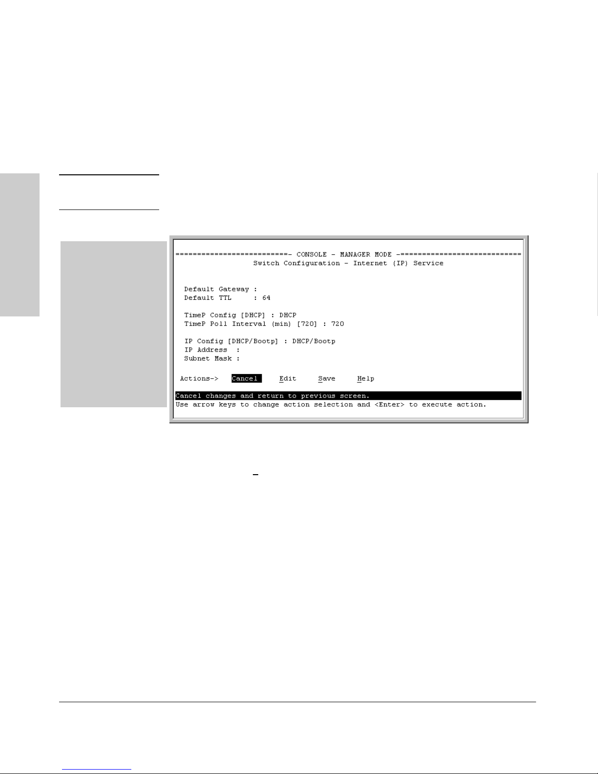
Configuring IP Addressing, Interface Access, and System Information
IP Configuration
To Configure IP Addressing.
1. From the Main Menu, Select.
2. Switch Configuration ...
5. IP Configuration
Note If multiple VLANs are configured, a screen showing all VLANs appears instead
of the following screen.
The default setting for
TimeP Config is DHCP.
Setting it to Manual,
then pressing [v] or [Tab]
Interface Access, and
Configuring IP Addressing,
causes the Server
Address parameter to
appear.
For descriptions of these
parameters, see the
online Help for this
screen.
Before using the DHCP/
Bootp option, refer to
“DHCP/Bootp
Operation” on page 5-11.
5-6
Figure 5-1. Example of the IP Service Configuration Screen without Multiple
VLANs Configured
2. Press [E] (for Edit).
3. If the switch needs to access a router, for example, to reach off-subnet
destinations, select the Default Gateway field and enter the IP address of
the gateway router.
4. If you need to change the packet Time-To-Live (TTL) setting, select Default
TTL and type in a value between 2 and 255 (seconds).
5. At the TimeP Config field do one of the following:
• If you want the switch to obtain the IP address of the Timep server
via DHCP server, keep the value as DHCP.
• If you want to manually specify the IP address of the Timep server,
use the Space bar to select Manual.
• If you don’t have a Timep server set up, use the Space bar to change
the value to Disabled.
Page 91

Configuring IP Addressing, Interface Access, and System Information
IP Configuration
6. If you selected Manual , press [Tab] or [v], and additional fields will be
displayed for entering the IP address for the Timep server.
7. Select the TimeP Poll Interval field if you want to change the value for how
often the switch polls the Timep server for time information.
8. Do one of the following:
• If you want to have the switch retrieve its IP configuration from a
DHCP or Bootp server, at the IP Config field, keep the value as DHCP/
Bootp and go to step 11.
• If you want to manually configure the IP information, use the Space
bar to select Manual and use the [Tab] key to move to the other IP
configuration fields.
9. Select the IP Address field and enter the IP address for the switch.
10. Select the Subnet Mask field and enter the subnet mask for the IP address.
Configuring IP Addressing,
Interface Access, and
11. Press [Enter], then [S] (for S
ave).
CLI: Configuring IP Address, Gateway, Time-To-Live
(TTL), and Timep
IP Commands Used in This Section
show ip page 5-8
vlan <vlan-id> ip
address
ip default-gateway page 5-9
ip ttl page 5-9
[no] ip timep page 5-10
For a listing of the full CLI command set, including syntax and options, see
the CLI command reference available on the HP ProCurve website at:
http://www.hp.com/go/procurve
page 5-9
5-7
Page 92
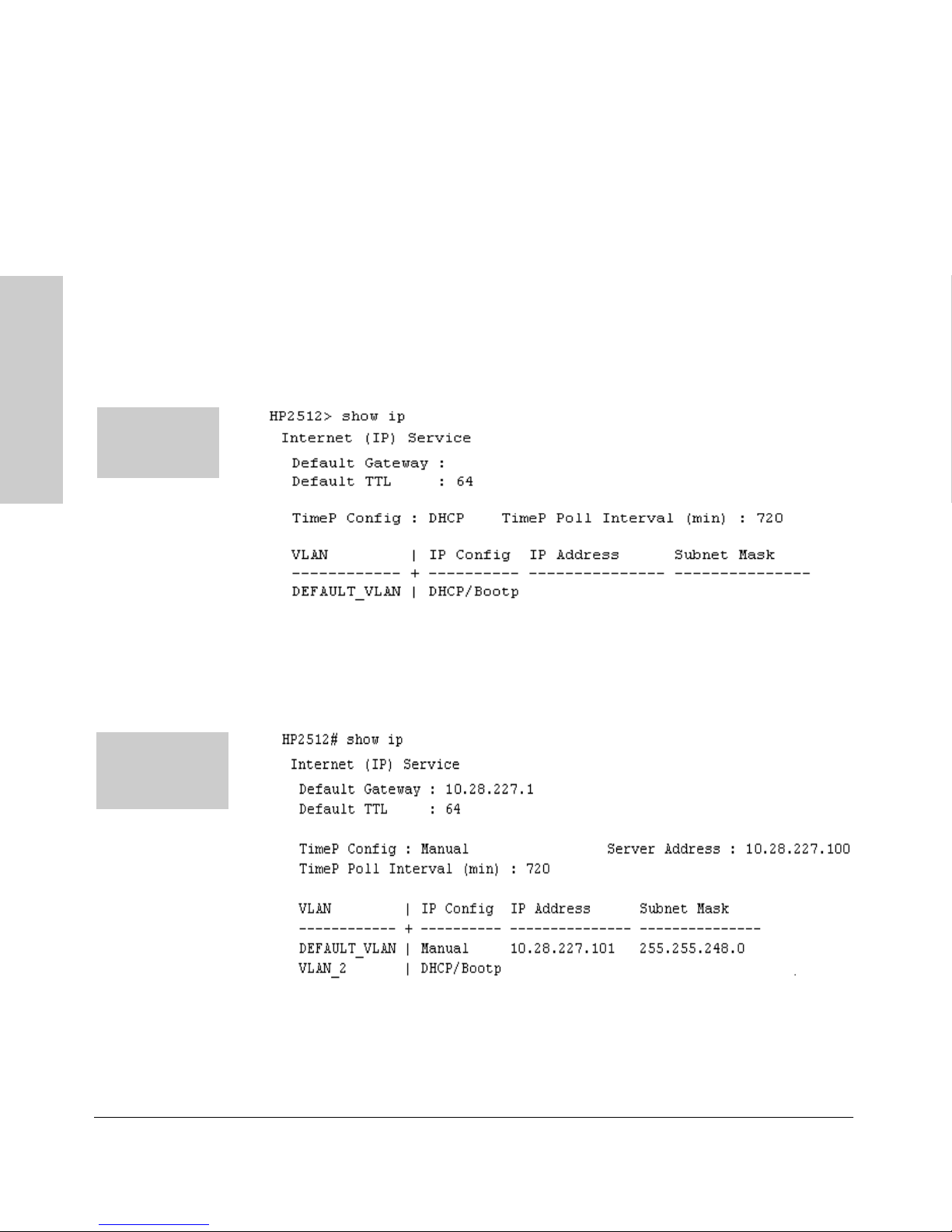
Configuring IP Addressing, Interface Access, and System Information
IP Configuration
Viewing the Current IP Configuration. The following command displays
the IP addressing for each VLAN configured in the switch. If only the
DEFAULT_VLAN exists, then its IP configuration applies to all ports in the
switch. Where multiple VLANs are configured, the IP addressing is listed per
VLAN. The display includes switch-wide packet time-to-live, and (if configured) the switch’s default gateway and Timep configuration.
Syntax: show ip
For example, in the factory-default configuration (no IP addressing assigned),
the switch’s IP addressing appears as:
The Default IP
Configuration on
Interface Access, and
a Switch 2512 or
2524
Configuring IP Addressing,
A Switch 2512 or
2524 with IP
Addressing and
VLANs Configured
Figure 5-2. Example of the Switch’s Default IP Addressing
With multiple VLANs and some other features configured, show ip provides
additional information:
Figure 5-3. Example of Show IP Listing with Non-Default IP Addressing Configured
(If DHCP/Bootp acquires an IP address and Subnet Mask for VLAN_2, they
will appear in the appropriate columns.)
5-8
Page 93

Configuring IP Addressing, Interface Access, and System Information
IP Configuration
Configure an IP Address and Subnet Mask. The following command
includes both the IP address and the subnet mask. You must either include the
ID of the VLAN for which you are configuring IP addressing or go to the
context configuration level for that VLAN. (If you are not using VLANs on the
switch—that is, if the only VLAN is the default VLAN—then the VLAN ID is
always “1”.)
Note The default IP address setting for the DEFAULT_VLAN is DHCP/Bootp. On
additional VLANs you create, the default IP address setting is Disabled.
Syntax: vlan <vlan-id> ip address <ip-address/mask-length>
or
vlan <vlan-id> ip address <ip-address> <mask-bits>
or
vlan <vlan-id> ip address dhcp-bootp
This example configures IP addressing on the default VLAN with the subnet
mask specified in mask bits.
Configuring IP Addressing,
Interface Access, and
HP2512(config)# vlan 1 ip address 10.28.227.103/255.255.255.0
This example configures the same IP addressing as the preceding example,
but specifies the subnet mask by mask length.
HP2512(config)# vlan 1 ip address 10.28.227.103/24
Configure the Optional Default Gateway. You can assign one default
gateway to the switch.
Syntax: ip default-gateway <ip-address>
For example:
HP2512(config)# ip default-gateway 11.28.227.115
You can execute this command only from the global configuration level.
Configure Time-To-Live (TTL). This command sets the time that a packet
outbound from the switch can exist on the network. The default setting is 64
seconds.
Syntax: ip ttl <number-of-seconds>
HP2512(config)# ip ttl 60
5-9
Page 94

Configuring IP Addressing, Interface Access, and System Information
IP Configuration
In the CLI, you can execute this command only from the global configuration
level. The TTL range is 2 - 255 seconds.
Configure the Optional Timep Server.
Syntax: [no] ip timep <dhcp | manual <ip-address> > [interval <1-9999>]
You can specify whether the address of the Timep server is assigned via DHCP
or manually, and the interval in minutes between Timep queries (1-9999
minutes; default 720 minutes). The following examples show the Timep
command options:
HP2512(config)# ip timep manual 10.28.227.1 interval 60
HP2512(config)# ip timep manual 10.28.227.1
Interface Access, and
Configuring IP Addressing,
HP2512(config)# ip timep dhcp
HP2512(config)# ip timep dhcp interval 60
HP2512(config)# no ip timep
Web: Configuring IP Addressing
You can use the web browser interface to access IP addressing only if the
switch already has an IP address that is reachable through your network.
1. Click on the Configuration tab.
2. Click on [IP Configuration].
3. If you need further information on using the web browser interface, click
on [?] to access the web-based help available for the Switch 2512/2524.
How IP Addressing Affects Switch Operation
Without an IP address and subnet mask compatible with your network, the
switch can be managed only through a direct terminal device connection to
the Console RS-232 port. You can use direct-connect console access to take
advantage of features that do not depend on IP addressing. However, to realize
the full performance capabilities HP proactive networking offers through the
switch, configure the switch with an IP address and subnet mask compatible
with your network. The following table lists the general features available with
and without a network-compatible IP address configured.
5-10
Page 95

Configuring IP Addressing, Interface Access, and System Information
IP Configuration
Table 5-1. Features Available With and Without IP Addressing on the Switch
Features Available Without an IP Address Additional HP Proactive Networking Features Available
with an IP Address and Subnet Mask
• Direct-connect access to the CLI and the menu
interface.
• Stacking Candidate or Stack Member
• DHCP or Bootp support for automatic IP address
configuration, and DHCP support for automatic Timep
server IP address configuration
• Spanning Tree Protocol
• Port settings and port trunking
• Console-based status and counters information for
monitoring switch operation and diagnosing problems
through the CLI or menu interface.
• VLANs
• GVRP
• Serial downloads of operating system (OS) updates
and configuration files (Xmodem)
• Link test
• Port monitoring
• Security
*Although a Commander can operate without an IP address, doing so makes it unavailable for in-band access in an
IP network.
• HP web browser interface access, with configuration,
security, and diagnostic tools, plus the Alert Log for
discovering problems detected in the switch along
with suggested solutions
• SNMP network management access such as HP
TopTools network configuration, monitoring, problemfinding and reporting, analysis, and recommendations
for changes to increase control and uptime
• Stacking Commander*
• Telnet access to the CLI or the menu interface
• IGMP
• Timep server configuration
• TFTP download of configurations and OS updates
• Ping test
DHCP/Bootp Operation
Configuring IP Addressing,
Interface Access, and
Overview. DHCP/Bootp is used to provide configuration data from a DHCP
or Bootp server to the switch. This data can be the IP address, subnet mask,
default gateway, Timep Server address, and TFTP server address. If a TFTP
server address is provided, this allows the switch to TFTP a previously saved
configuratin file from the TFTP server to the switch. With either DHCP or
Bootp, the servers must be configured prior to the switch being connected to
the network.
Note The Switches 2512 and 2524 are compatible with both DHCP and Bootp
servers.
The DHCP/Bootp Process. Whenever the IP Config parameter in the switch
or in an individual VLAN in the switch is configured to DHCP/Bootp (the
default), or when the switch is rebooted with this configuration:
5-11
Page 96

Configuring IP Addressing, Interface Access, and System Information
IP Configuration
1. DHCP/Bootp requests are automatically broadcast on the local network.
(The switch sends one type of request to which either a DHCP or Bootp
server can respond.)
2. When a DHCP or Bootp server receives the request, it replies with a
previously configured IP address and subnet mask for the switch. The
switch also receives an IP Gateway address if the server has been configured to provide one. In the case of Bootp, the server must first be
configured with an entry that has the MAC address of the switch. (To
determine the switch’s MAC address, see appendix B, “MAC Address
Management”. The switch properly handles replies from either type of
server. If multiple replies are returned, the switch tries to use the first
reply.)
Interface Access, and
Configuring IP Addressing,
Note If you manually configure a gateway on the switch, it will ignore any gateway
address received via DHCP or Bootp.
If the switch is initially configured for DHCP/Bootp operation (the default),
or if it is rebooted with this configuration, it immediately begins sending
request packets on the network. If the switch does not receive a reply to its
DHCP/Bootp requests, it continues to periodically send request packets, but
with decreasing frequency. Thus, if a DHCP or Bootp server is not available
or accessible to the switch when DHCP/Bootp is first configured, the switch
may not immediately receive the desired configuration. After verifying that
the server has become accessible to the switch, reboot the switch to re-start
the process immediately.
DHCP Operation. A significant difference between a DHCP configuration
and a Bootp configuration is that an IP address assignment from a DHCP
server is automatic. Depending on how the DHCP server is configured, the
switch may receive an ip address that is temporarily leased. Periodically the
switch may be required to renew its lease of the IP configuration. Thus, the IP
addressing provided by the server may be different each time the switch
reboots or renews its configuration from the server. However, you can fix the
address assignment for the switch by doing either of the following:
■ Configure the server to issue an “infinite” lease.
■ Using the switch’s MAC address as an identifier, configure the server with
a “Reservation” so that it will always assign the same IP address to the
switch. (For MAC address information, refer to appendix B, “MAC
Address Management”.)
For more information on either of these procedures, refer to the documentation provided with the DHCP server.
5-12
Page 97

Configuring IP Addressing, Interface Access, and System Information
IP Configuration
Bootp Operation. When a Bootp server receives a request it searches its
Bootp database for a record entry that matches the MAC address in the Bootp
request from the switch. If a match is found, the configuration data in the
associated database record is returned to the switch. For many Unix systems,
the Bootp database is contained in the /etc/bootptab file. In contrast to DHCP
operation, Bootp configurations are always the same for a specific receiving
device. That is, the Bootp server replies to a request with a configuration
previously stored in the server and designated for the requesting device.
Bootp Database Record Entries. A minimal entry in the Bootp table file
/etc/bootptab to update an IP address and subnet mask to the switch or a VLAN
configured in the switch would be similar to this entry:
j2512switch:\
ht=ether:\
ha=0030c1123456:\
ip=10.66.77.88:\
sm=255.255.248.0:\
gw=10.66.77.1:\
hn:\
vm=rfc1048
Configuring IP Addressing,
Interface Access, and
An entry in the Bootp table file /etc/bootptab to tell the switch or VLAN
where to obtain a configuration file download would be similar to this entry:
j2512switch:\
ht=ether:\
ha=0030c1123456:\
ip=10.66.77.88:\
sm=255.255.248.0:\
gw=10.66.77.1:\
lg=10.22.33.44:\
T144=”switch.cfg”:\
vm=rfc1048
where:
j2512switch is a user-defined symbolic name to help you find the correct section of the
bootptab file. If you have multiple switches that will be using Bootp to get their
IP configuration, you should use a unique symbolic name for each switch.
ht is the “hardware type”. For the Switches 2512 and 2524, set this to ether (for
Ethernet). This tag must precede the ha tag.
ha is the “hardware address”. Use the switch's (or VLAN's) 12-digit MAC address.
ip is the IP address to be assigned to the switch (or VLAN).
sm is the subnet mask of the subnet in which the switch (or VLAN) is installed.
5-13
Page 98

Configuring IP Addressing, Interface Access, and System Information
IP Configuration
gw is the IP address of the default gateway.
lg TFTP server address (source of final configuration file)
T144 is the vendor-specific “tag” identifying the configuration file to download.
vm is a required entry that specifies the Bootp report format. For the Switches 2512
and 2524, set this parameter to rfc1048.
Note The above Bootp table entry is a sample that will work for the Switches 2512
and 2524 when the appropriate addresses and file names are used.
Network Preparations for Configuring DHCP/Bootp
In its default configuration, the switch is configured for DHCP/Bootp opera-
Interface Access, and
Configuring IP Addressing,
tion. However, the DHCP/Bootp feature will not acquire IP addressing for the
switch unless the following tasks have already been completed:
■ For Bootp operation:
• A Bootp database record has already been entered into an appropriate
Bootp server.
• The necessary network connections are in place
• The Bootp server is accessible from the switch
■ For DHCP operation:
• A DHCP scope has been configured on the appropriate DHCP server.
• The necessary network connections are in place
• A DHCP server is accessible from the switch
Note Designating a primary VLAN other than the default VLAN affects the switch’s
use of information received via DHCP/Bootp. For more on this topic, see
“Which VLAN Is Primary?” on page 9-53.
After you reconfigure or reboot the switch with DHCP/Bootp enabled in a
network providing DHCP/Bootp service, the switch does the following:
■ Receives an IP address and subnet mask and, if configured in the server,
a gateway IP address and the address of a Timep server.
■ If the DHCP/Bootp reply provides information for downloading a config-
uration file, the switch uses TFTP to download the file from the designated
source, then reboots itself. (This assumes that the switch or VLAN has
connectivity to the TFTP file server specified in the reply, that the configuration file is correctly named, and that the configuration file exists in the
TFTP directory.)
5-14
Page 99

Configuring IP Addressing, Interface Access, and System Information
IP Configuration
Globally Assigned IP Network Addresses
If you intend to connect your network to other networks that use globally
administered IP addresses, Hewlett-Packard strongly recommends that you
use IP addresses that have a network address assigned to you. There is a
formal process for assigning unique IP addresses to networks worldwide. For
more information:
Please contact your internet service provider (ISP).
If you need more information than your ISP can provide, contact one of the
following organizations:
Country Phone Number/E-Mail/URL Company Name/Address
Configuring IP Addressing,
Interface Access, and
United States/
Countries not in
Europe or Asia/Pacific
Europe +31 20 535 4444
Asia/Pacific +61-7-3367-0490
1-310-823-9358
[email protected]
http://www.iana.org
[email protected]
http://www.ripe.net
[email protected]
http://www.apnic.net
The Internet Corporation for Assigned
Names and Numbers (ICANN)
4676 Admiralty Way, Suite 330
Marina Del Rey, CA 90292
USA
RIPE NCC
Singel 258
1016 AB Amsterdam
The Netherlands
Attention: IN-ADDR.ARPA Registration
Asia Pacific Network Information Center
Level 1, 33 Park Road
PO Box 2131
Milton, QLD 4064
Australia
For more information, refer to Internetworking with TCP/IP: Principles,
Protocols and Architecture by Douglas E. Comer (Prentice-Hall, Inc.,
publisher).
5-15
Page 100

Configuring IP Addressing, Interface Access, and System Information
Interface Access: Console/Serial Link, Web, and Inbound Telnet
Interface Access: Console/Serial Link,
Web, and Inbound Telnet
Interface Access Features
Feature Default Menu CLI Web
Inactivity Time 0 Minutes
(disabled)
Inbound Telnet Access Enabled page 5-17 page 5-18 —
Web Browser Interface Access Enabled page 5-17 page 5-19 —
Interface Access, and
Configuring IP Addressing,
Terminal type VT-100 — page 5-19 —
Event Log event types to list
(Displayed Events)
Baud Rate Speed Sense — page 5-19 —
Flow Control XON/XOFF — page 5-19 —
All — page 5-19 —
page 5-17 page 5-19 —
In most cases, the default configuration is acceptable for standard operation.
Note Basic switch security is through passwords. You can gain additional security
using IP authorized managers. However if unauthorized access to the switch
through in-band means (Telnet or the web browser interface), then you can
disallow in-band access (as described in this section) and install the switch in
a locked environment.
5-16
 Loading...