

Page 1

HP ProCurve 1810G Switches
Management and Configuration Guide
Page 2

Page 3

HP ProCurve 1810G Switches
Management and Configuration Guide
August 2009
Page 4

© Copyright 2009 Hewlett-Packard Development Company, L.P.
The information contained herein is subject to change without notice. All Rights
Reserved.
This document contains proprietary information, which is protected by
copyright. No part of this document may be photocopied, reproduced, or
translated into another language without the prior written consent of
Hewlett-Packard.
Publication Number
5992-5475
August 2009
Applicable Products
HP ProCurve 1810G-8 Switch J9449A
HP ProCurve 1810G-24 Switch J9450A
Trademark Credits
Microsoft®, Windows®, and Windows NT® are US registered trademarks of
Microsoft Corporation. Java
TM
is a US trademark of Sun Microsystems, Inc.
Disclaimer
The information contained in this document is subject to change without
notice.
HEWLETT-PACKARD COMPANY MAKES NO WARRANTY OF ANY KIND
WITH REGARD TO THIS MATERIAL, INCLUDING, BUT NOT LIMITED TO,
THE IMPLIED WARRANTIES OF MERCHANTABILITY AND FITNESS FOR
A PARTICULAR PURPOSE. Hewlett-Packard shall not be liable for errors
contained herein or for incidental or consequential damages in connection
with the furnishing, performance, or use of this material.
The only warranties for HP products and services are set forth in the express
warranty statements accompanying such products and services. Nothing
herein should be construed as constituting an additional warranty. HP shall
not be liable for technical or editorial errors or omissions contained herein.
Hewlett-Packard assumes no responsibility for the use or reliability of its
software on equipment that is not furnished by Hewlett-Packard.
Warranty
See the HP ProCurve Software License, Warranty and Support booklet
included with the product.
A copy of the specific warranty terms applicable to your Hewlett-Packard
products and replacement parts can be obtained from your HP Sales and
Service Office or authorized dealer.
Hewlett-Packard Company
8000 Foothills Boulevard, m/s 5551
Roseville, California 95747-5551
www.hp.com/go/procurve
Page 5

Contents
Preface
About This Document . . . . . . . . . . . . . . . . . . . . . . . . . . . . . . . . . . . . . . . . . . . . . . . . . . . . . . . . . . . . . . . . . . . v
About Your Switch Manual Set . . . . . . . . . . . . . . . . . . . . . . . . . . . . . . . . . . . . . . . . . . . . . . . . . . . . . . . . . . .v
Overview of Switch Software Features . . . . . . . . . . . . . . . . . . . . . . . . . . . . . . . . . . . . . . . . . . . . . . . . . . . vi
1 Getting Started
Connecting the Switch to a Network . . . . . . . . . . . . . . . . . . . . . . . . . . . . . . . . . . . . . . . . . . . . . . . . . . . 1-1
Getting Started With the Web Interface . . . . . . . . . . . . . . . . . . . . . . . . . . . . . . . . . . . . . . . . . . . . . . . . . 1-2
Logging On . . . . . . . . . . . . . . . . . . . . . . . . . . . . . . . . . . . . . . . . . . . . . . . . . . . . . . . . . . . . . . . . . . . . . . 1-2
Interface Layout and Features . . . . . . . . . . . . . . . . . . . . . . . . . . . . . . . . . . . . . . . . . . . . . . . . . . . . . 1-3
Common Page Elements . . . . . . . . . . . . . . . . . . . . . . . . . . . . . . . . . . . . . . . . . . . . . . . . . . . . . . . . . . 1-3
Saving Changes . . . . . . . . . . . . . . . . . . . . . . . . . . . . . . . . . . . . . . . . . . . . . . . . . . . . . . . . . . . . . . . . . . 1-4
User-Defined Fields . . . . . . . . . . . . . . . . . . . . . . . . . . . . . . . . . . . . . . . . . . . . . . . . . . . . . . . . . . . . . . 1-4
Web Applet . . . . . . . . . . . . . . . . . . . . . . . . . . . . . . . . . . . . . . . . . . . . . . . . . . . . . . . . . . . . . . . . . . . . . 1-4
2 Status Pages
System Description . . . . . . . . . . . . . . . . . . . . . . . . . . . . . . . . . . . . . . . . . . . . . . . . . . . . . . . . . . . . . . . . . . 2-1
Log . . . . . . . . . . . . . . . . . . . . . . . . . . . . . . . . . . . . . . . . . . . . . . . . . . . . . . . . . . . . . . . . . . . . . . . . . . . . . . . . 2-2
Port Summary . . . . . . . . . . . . . . . . . . . . . . . . . . . . . . . . . . . . . . . . . . . . . . . . . . . . . . . . . . . . . . . . . . . . . . 2-3
LLDP Statistics . . . . . . . . . . . . . . . . . . . . . . . . . . . . . . . . . . . . . . . . . . . . . . . . . . . . . . . . . . . . . . . . . . . . . . 2-5
Trunk . . . . . . . . . . . . . . . . . . . . . . . . . . . . . . . . . . . . . . . . . . . . . . . . . . . . . . . . . . . . . . . . . . . . . . . . . . . . . . 2-7
MAC Table . . . . . . . . . . . . . . . . . . . . . . . . . . . . . . . . . . . . . . . . . . . . . . . . . . . . . . . . . . . . . . . . . . . . . . . . . 2-8
Loop Protection . . . . . . . . . . . . . . . . . . . . . . . . . . . . . . . . . . . . . . . . . . . . . . . . . . . . . . . . . . . . . . . . . . . . . 2-9
Dual Image . . . . . . . . . . . . . . . . . . . . . . . . . . . . . . . . . . . . . . . . . . . . . . . . . . . . . . . . . . . . . . . . . . . . . . . . 2-10
Clock . . . . . . . . . . . . . . . . . . . . . . . . . . . . . . . . . . . . . . . . . . . . . . . . . . . . . . . . . . . . . . . . . . . . . . . . . . . . . 2-11
3 Network Setup
Get Connected . . . . . . . . . . . . . . . . . . . . . . . . . . . . . . . . . . . . . . . . . . . . . . . . . . . . . . . . . . . . . . . . . . . . . . 3-1
Simple Network Time Protocol . . . . . . . . . . . . . . . . . . . . . . . . . . . . . . . . . . . . . . . . . . . . . . . . . . . . . . . . 3-3
Time Zone . . . . . . . . . . . . . . . . . . . . . . . . . . . . . . . . . . . . . . . . . . . . . . . . . . . . . . . . . . . . . . . . . . . . . . . . . . 3-4
Daylight Savings Time . . . . . . . . . . . . . . . . . . . . . . . . . . . . . . . . . . . . . . . . . . . . . . . . . . . . . . . . . . . . . . . . 3-5
4 Switching Pages
Port Configuration . . . . . . . . . . . . . . . . . . . . . . . . . . . . . . . . . . . . . . . . . . . . . . . . . . . . . . . . . . . . . . . . . . . 4-1
Jumbo Frames . . . . . . . . . . . . . . . . . . . . . . . . . . . . . . . . . . . . . . . . . . . . . . . . . . . . . . . . . . . . . . . . . . . . . . 4-2
Port Mirroring . . . . . . . . . . . . . . . . . . . . . . . . . . . . . . . . . . . . . . . . . . . . . . . . . . . . . . . . . . . . . . . . . . . . . . 4-3
Flow Control . . . . . . . . . . . . . . . . . . . . . . . . . . . . . . . . . . . . . . . . . . . . . . . . . . . . . . . . . . . . . . . . . . . . . . . 4-4
Green Features . . . . . . . . . . . . . . . . . . . . . . . . . . . . . . . . . . . . . . . . . . . . . . . . . . . . . . . . . . . . . . . . . . . . . . 4-5
iii
Page 6

Loop Protection . . . . . . . . . . . . . . . . . . . . . . . . . . . . . . . . . . . . . . . . . . . . . . . . . . . . . . . . . . . . . . . . . . . . . 4-6
5 Security
Advanced Security . . . . . . . . . . . . . . . . . . . . . . . . . . . . . . . . . . . . . . . . . . . . . . . . . . . . . . . . . . . . . . . . . . . 5-1
Secure Connection . . . . . . . . . . . . . . . . . . . . . . . . . . . . . . . . . . . . . . . . . . . . . . . . . . . . . . . . . . . . . . . . . . 5-2
Downloading SSL Certificates and Diffie-Hellman Files . . . . . . . . . . . . . . . . . . . . . . . . . . . . . . . . 5-4
Generating Certificates . . . . . . . . . . . . . . . . . . . . . . . . . . . . . . . . . . . . . . . . . . . . . . . . . . . . . . . . . . . 5-5
6Trunks
Trunk Configuration . . . . . . . . . . . . . . . . . . . . . . . . . . . . . . . . . . . . . . . . . . . . . . . . . . . . . . . . . . . . . . . . . 6-1
Trunk Membership . . . . . . . . . . . . . . . . . . . . . . . . . . . . . . . . . . . . . . . . . . . . . . . . . . . . . . . . . . . . . . . . . . 6-3
7 Virtual LAN
VLAN Configuration . . . . . . . . . . . . . . . . . . . . . . . . . . . . . . . . . . . . . . . . . . . . . . . . . . . . . . . . . . . . . . . . . 7-1
VLAN Ports . . . . . . . . . . . . . . . . . . . . . . . . . . . . . . . . . . . . . . . . . . . . . . . . . . . . . . . . . . . . . . . . . . . . . . . . . 7-2
Participation / Tagging . . . . . . . . . . . . . . . . . . . . . . . . . . . . . . . . . . . . . . . . . . . . . . . . . . . . . . . . . . . . . . . 7-3
Example—Creating a Management VLAN . . . . . . . . . . . . . . . . . . . . . . . . . . . . . . . . . . . . . . . . . . . . . . . 7-5
8 Link Layer Discovery Protocol (LLPD)
LLDP Configuration . . . . . . . . . . . . . . . . . . . . . . . . . . . . . . . . . . . . . . . . . . . . . . . . . . . . . . . . . . . . . . . . . . 8-1
LLDP Local Device . . . . . . . . . . . . . . . . . . . . . . . . . . . . . . . . . . . . . . . . . . . . . . . . . . . . . . . . . . . . . . . . . . 8-3
LLDP Remote Device . . . . . . . . . . . . . . . . . . . . . . . . . . . . . . . . . . . . . . . . . . . . . . . . . . . . . . . . . . . . . . . . 8-4
9 Diagnostics
Ping Test . . . . . . . . . . . . . . . . . . . . . . . . . . . . . . . . . . . . . . . . . . . . . . . . . . . . . . . . . . . . . . . . . . . . . . . . . . . 9-1
Log Configuration . . . . . . . . . . . . . . . . . . . . . . . . . . . . . . . . . . . . . . . . . . . . . . . . . . . . . . . . . . . . . . . . . . . 9-2
Reboot Switch . . . . . . . . . . . . . . . . . . . . . . . . . . . . . . . . . . . . . . . . . . . . . . . . . . . . . . . . . . . . . . . . . . . . . . 9-3
Factory Defaults . . . . . . . . . . . . . . . . . . . . . . . . . . . . . . . . . . . . . . . . . . . . . . . . . . . . . . . . . . . . . . . . . . . . 9-4
Support File . . . . . . . . . . . . . . . . . . . . . . . . . . . . . . . . . . . . . . . . . . . . . . . . . . . . . . . . . . . . . . . . . . . . . . . . 9-5
Locator . . . . . . . . . . . . . . . . . . . . . . . . . . . . . . . . . . . . . . . . . . . . . . . . . . . . . . . . . . . . . . . . . . . . . . . . . . . . 9-6
10 Maintenance Pages
Backup Manager . . . . . . . . . . . . . . . . . . . . . . . . . . . . . . . . . . . . . . . . . . . . . . . . . . . . . . . . . . . . . . . . . . . 10-1
Example—Backing Up a Configuration File . . . . . . . . . . . . . . . . . . . . . . . . . . . . . . . . . . . . . . . . 10-2
Update Manager . . . . . . . . . . . . . . . . . . . . . . . . . . . . . . . . . . . . . . . . . . . . . . . . . . . . . . . . . . . . . . . . . . . . 10-4
Example—Updating the Switch Software . . . . . . . . . . . . . . . . . . . . . . . . . . . . . . . . . . . . . . . . . . 10-5
Password Manager . . . . . . . . . . . . . . . . . . . . . . . . . . . . . . . . . . . . . . . . . . . . . . . . . . . . . . . . . . . . . . . . . 10-8
Save Configuration . . . . . . . . . . . . . . . . . . . . . . . . . . . . . . . . . . . . . . . . . . . . . . . . . . . . . . . . . . . . . . . . . 10-9
Dual Image Configuration . . . . . . . . . . . . . . . . . . . . . . . . . . . . . . . . . . . . . . . . . . . . . . . . . . . . . . . . . . . 10-9
iv
Page 7

Preface
Preface
About This Document
HP ProCurve 1810G switch software provides rich layer 2 and Quality of Service (QoS) functionality
for switches operating in small business networks. This guide describes how to configure HP ProCurve
1810G switch software features by using the Web-based graphical user interface (GUI).
Audience
The information in this guide is primarily intended for System administrators and Support providers
who are responsible for configuring, operating, or supporting a network using HP ProCurve 1810G
switch software. An understanding of the software specifications for the networking device platform,
and a basic knowledge of Ethernet and networking concepts, are presumed.
About Your Switch Manual Set
The switch manual set includes the following:
■ Read Me First - a printed guide shipped with your switch. Provides software update
information, product notes, and other information.
■ Quick Setup Guide - a printed guide shipped with your switch. Provides illustrations for basic
installation and setup guidelines.
■ Regulatory and Safety Information - printed documentation shipped with your switch.
Includes Regulatory statements and standards supported by the switch, along with product
specifications.
■ Installation and Getting Started Guide - a PDF file on the HP ProCurve Web site. Provides
detailed installation guide for your switch, including physical installation on your network,
basic troubleshooting, product specifications, supported accessories, Regulatory and Safety
information.
■ Management and Configuration Guide - a PDF file on the HP ProCurve Web site. This guide
describes how to manage and configure switch features using a Web browser interface.
■ Release Notes - a PDF file on the HP ProCurve Web site. Provides information on software
updates. The Release Notes describe new features, fixes, and enhancements that become
available between revisions of the above guides.
v
Page 8

Preface
Note For the latest version of all HP ProCurve documentation, visit the HP ProCurve Networking Web site
at www.hp.com/go/procurve/manuals. Then select your switch product.
Overview of Switch Software Features
HP ProCurve 1810G switches include support for the following features:
Feature 1810G-8 1810G-24
802.1Q VLAN Tagging Yes Yes
802.1p Packet priority Yes Yes
Config file 1 1
Config file backup (TFTP/HTTP) Yes Ye s
DHCP Client Yes Yes
Diagnostic Tools Yes Ye s
Event Log Yes Yes
Factory-Default IP Address 192.168.2.10 192.168.2.10
Factory-Default Subnet Mask 255.255.255.0 255.255.255.0
Green Features (transceiver off, LEDs off) Yes Ye s
Interface for Management Access Web browser only Web browser only
Jumbo Frames (up to 9216 bytes) Yes Ye s
Port Trunking (LACP) Yes Yes
Ports per trunk (maximum) 4 4
Trunks per switch (maximum) 4 8
LLDP Yes Ye s
Locator LED Yes Yes
Loop Protection Yes Ye s
MAC Address table (maximum) 8192 8192
Network Management Applications (LLDP, SNMP) Yes Ye s
Password Yes Yes
Ping Yes Ye s
Port Configuration Yes Yes
Port Mirroring Yes Ye s
vi
Page 9

Feature 1810G-8 1810G-24
Port Status Yes Yes
Security: Denial of Service (DoS) Yes Ye s
Security: Storm Control Protection Yes Yes
SNMP Read Only Read Only
Software Downloads (TFTP, HTTP) Yes Yes
SSL (Secure Socket Layer) Yes Ye s
Syslog Yes Yes
System Information Yes Ye s
Time Protocol (SNTP) Yes Yes
Troubleshooting Yes Ye s
VLANs (maximum) 64 64
Preface
vii
Page 10

Preface
viii
Page 11

Getting Started
This chapter describes how to make the initial connections to the switch and provides an overview of
the Web interface.
Connecting the Switch to a Network
To enable remote management of the switch through a Web browser, the switch must be connected to
the network. The switch is pre-configured with an IP address for management purposes. After initial
configuration, the switch can also be configured to acquire its address from a DHCP server on the
network.
By default, the switch is assigned the following static IP information for access to the Web interface:
■ IP address: 192.168.2.10
■ Network mask: 255.255.255.0
■ Gateway: 0.0.0.0
1
1. Connect the switch to the management PC or to the network using any of the available network
ports.
2. Power on the switch.
3. Set the IP address of the management PC’s network adaptor to be in the same subnet as the switch.
Example: Set it to IP address 192.168.2.12, mask 255.255.255.0.
4. Enter the IP address shown above in the Web browser. See page 1-2 for browser requirements.
Thereafter, use the Web interface to configure a different IP address or configure the switch as a DHCP
client so that it receives a dynamically assigned IP address from the network.
Note ■ If you enable DHCP for IP network configuration, the switch must be connected to the same
network as the DHCP server. You will need to access your DHCP server to determine the IP
address assigned to the switch.
■ The switch supports LLDP (Link Layer Discovery Protocol), allowing discovery of its IP
address from a connected device or management station.
■ If DHCP is used for configuration and the switch fails to be configured, the IP address
192.168.2.10 is reassigned.
After the switch is able to communicate on your network, enter its IP address into your Web browser’s
address field to access the switch management features.
1-1
Page 12

Getting Started
Getting Started With the Web Interface
Getting Started With the Web Interface
This section describes the following Web pages:
■ “Logging On” on page 4
■ “Interface Layout and Features” on page 5
Logging On
Note Please use one of the following browsers to access the Web interface:
■ Internet Explorer 6.0, 7.0
■ Firefox 2.0, up to 3.04
■ JavaScript must be enabled on the browser to access the Web interface correctly.
Follow these steps to log on through Web interface:
1. Open a Web browser and enter the IP address of the switch in the Web browser address field.
2. On the Login page, enter the password (if one has been set), and then click Login.
By default, there is no password. After the initial log on, the administrator may configure a
password.
Note To set passwords, see “Password Manager” on page 10-8.
Figure 1-1. Login Page
1-2
Page 13
Interface Layout and Features
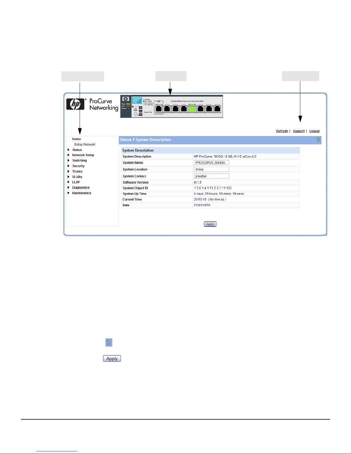
Navigation Pane
Web Applet
Common Links
Figure 1-2 shows the initial view.
Figure 1-2. Interface Layout and Features
Getting Started With the Web Interface
Getting Started
Click on any topic in the navigation page to display related configuration options.
The System Description page displays when you first log on and when you click Home or Status > System
Description in the navigation pane. See “System Description” on page 2-1 for more information.
You can click the Setup Network link beneath Home to display the Get Connected page, which you use
to set up a management connection to the switch. You can also click Network Setup > Get Connected to
display this page. See “Get Connected” on page 3-1 for more information.
The Web Applet displays summary information for the switch LEDs and port status in a graphical
format. For information on the Web Applet, see “Web Applet” on page 1-4.
Common Page Elements
■ Click on each page to display a help panel that explains the fields and configuration
options on the page.
■ Click to send the updated configuration to the switch. Configuration changes take
effect immediately, but some changes are not retained across a power cycle unless the changes
are saved to the system configuration file.
1-3
Page 14
Getting Started
LED Mode
System LEDs
Port Configuration and Summary
(Point, left-click, or right-click on any port for options)
Getting Started With the Web Interface
CAUTION Configuration changes take effect immediately, but some changes are not retained across a
power cycle (or reboot) unless the changes are saved to the system configuration file. See
“Saving Changes” below.
■ Click Refresh to refresh the page with the latest information from the switch.
■ Click Support to access the HP ProCurve Web site (Internet access required).
■ Click Logout to end the current management session.
Saving Changes
When you click , changes are saved only for the current boot session. The changes will not be
retained after a reboot. To ensure changes to the system configuration file are saved so that they are
retained after a reboot:
1. Click Maintenance > Save Configuration in the Navigation pane.
2. On the Save page, click .
User-Defined Fields
User-defined fields can contain 1–31 characters, unless otherwise noted on the configuration Web page. All characters may
be used except for the following (unless specifically noted for that feature):
\<*|
/>|?
Web Applet
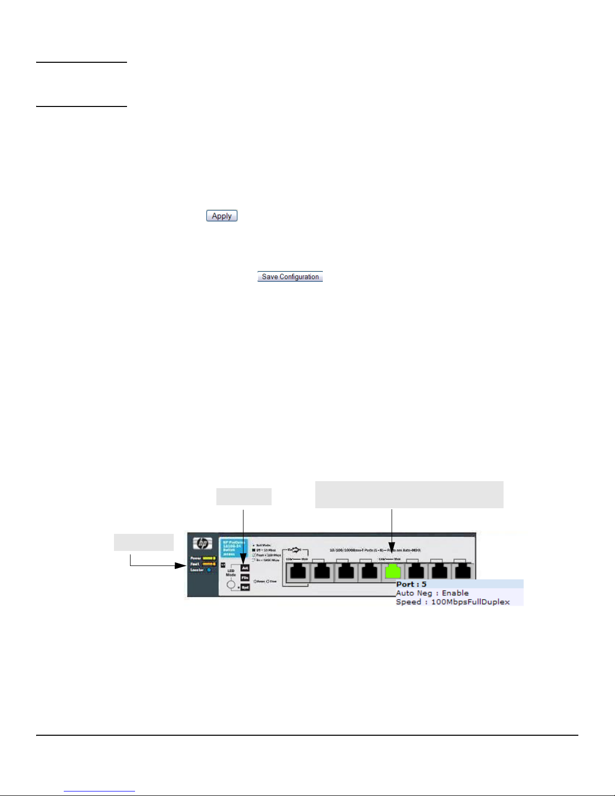
The Web Applet, as shown in Figure 1-3, displays at the top of the every page. It is a graphic
representation of the switch and provides information regarding the status parameters of individual
ports. The Web Applet enables easy system configuration and Web-based navigation.
Figure 1-3. Web Applet
■ Port Configuration and Summary — You can point to any port to display the following
information about the port:
• Auto Negotiation Status
•Speed
Left-click a port to display its Port Configuration page, or right-click and select from the menu to
display its Port Configuration Page or the Port Summary page for all ports.
1-4
Page 15

Getting Started With the Web Interface
■ System LEDs— You can point to the System LEDs area to view information about the switch
Getting Started
LEDs.
Note The System LED area provides general, static information about the LEDs only. The display does not
change to reflect the current state of the LEDs.
Switch LEDs include the following:
• Power (Green)
– On— The system is being powered by AC/DC power or Power-over-Ethernet (PoE).
– Blinking — Power from the PoE port is lost or insufficient. The LED continues to blink
until PoE is restored or the system is reset.
– Off—The system is powered by the external power adapter.
Note 8-port HP ProCurve 1810G switches may be PoE Powered Devices (PD) through port 1 only. (24-port
ProCurve 1810G switches do not support PoE). The 8-port switches provide an additional PD LED,
which turns On if it is receiving PoE power through port 1.
• Fault (Orange)
– Blinking—A fault has occurred, other than during self-test.
– On— Failure during self-test.
– Off—The switch is operating properly.
• Locator — When on, the switch is in Locate Mode so that it can be physically located. This
mode can be enabled using the Web interface. See “Locator” on page 9-6.
■ LED Mode—Each port has two LEDs. The function of the right LED (called the Mode LED)
changes depending on the LED mode selected for the switch. Use the LED Mode button on
the switch to select a mode (Act, FDx, Spd).
You can move your cursor over the LED Mode area to view a description of the LED modes.
Note The LED modes area provides general, static information about the LEDs. The display does not change
to reflect the current state of the LEDs. The physical LED Mode behavior is described below.
On the switch, the active LED mode is indicated by three LEDs:
■ Act—Activity. When Act mode is selected, the Mode LED for each port will blink upon port
activity.
■ FDx—Full Duplex. When FDx mode is selected, the Mode LED for each active port will
illuminate only when the port is operating in full-duplex mode.
■ Spd—Speed. When Spd mode is selected, the Mode LED for each active port will illuminate
when the port is operating at 100 Mbps (blinking) or 1000 Mbps (solid on), or will be off when
the port is operating at 10 Mbps.
If the LED Mode button is not pressed for 10 minutes, the LED mode automatically returns to Activity
mode.
If Green Mode is enabled (see “Green Features” on page 4-5), which turns off the port LEDs, pressing
the LED Mode button temporarily restores the LED Mode feature.
1-5
Page 16

Getting Started
Getting Started With the Web Interface
Note The left-port LED is not depicted in the Web Applet. It indicates link status, as follows:
■ On—The port is enabled and receiving a link indication or other signal from the connected
device.
■ Blinking—The port has experienced a self-test fault.
■ Off—The port has no active network cable connected, is not receiving link signal, or is
disabled.
1-6
Page 17

Status Pages
You can use the Status pages to view system information and statistics.
System Description
The System Description page displays when you first log on and when you click Home or Status > System
Description in the navigation pane. It displays basic information such as the software version and system
up time. In addition, the system name, location, and contact can be configured on this page.
Figure 2-1. System Description Page
2
■ Click Apply to save any changes for the current boot session; the changes take effect
immediately. Use the Maintenance > Save Configuration page to have the settings remain in effect
after a reboot.
2-1
Page 18
Status Pages
Log
Log
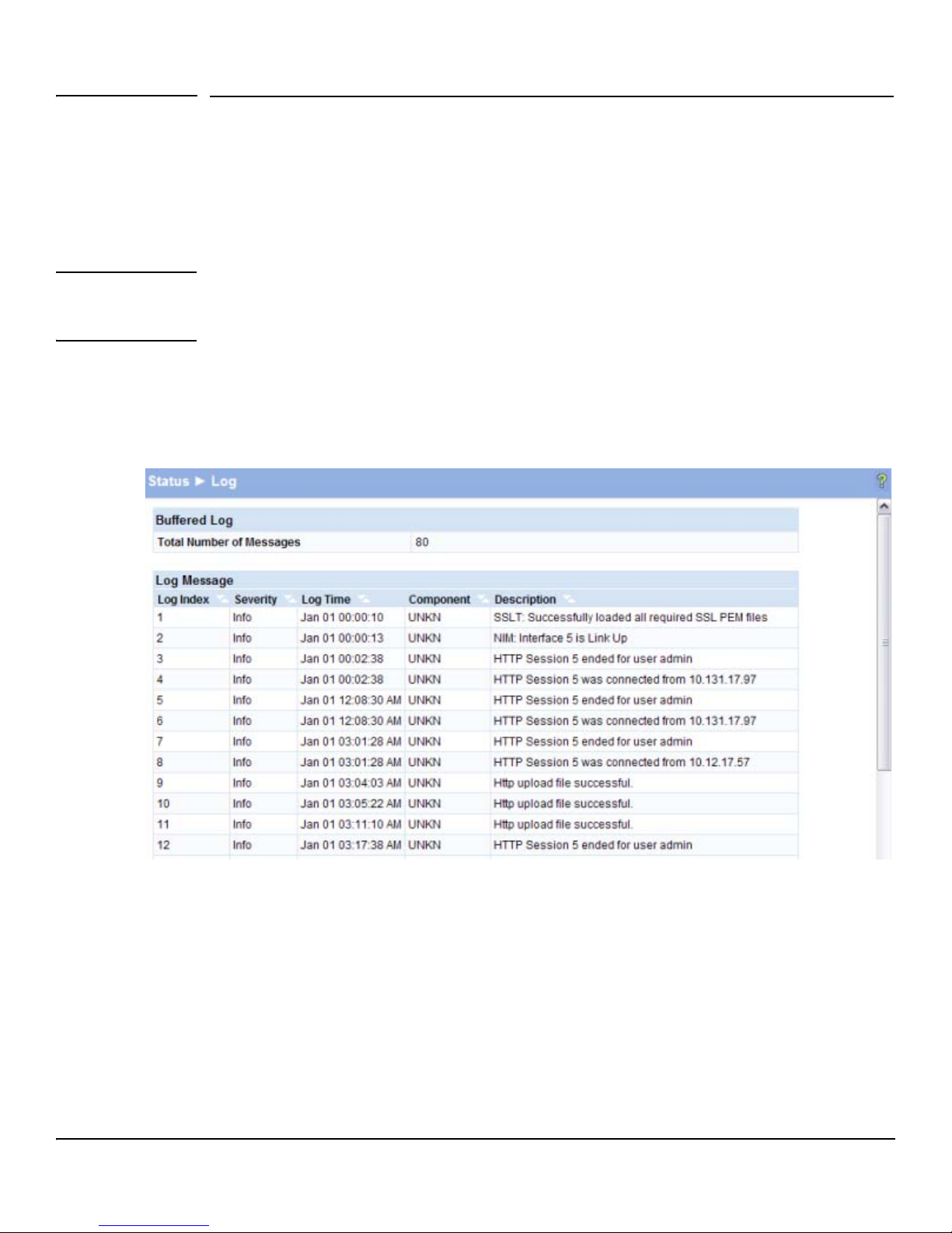
The Log table displays logged system messages, such as configuration failures and user sessions. The
log page displays the 100 most recent log entries. The newest log entry, by default, is displayed at the
bottom of the list.
Note If more than 100 logs accumulate, their Log Index numbers continue to increment beyond 100 and the
oldest entries are deleted (for example, if 200 log entries were generated since the system was last
restarted or the log file was cleared, then the log file would display entries 101–200).
To display this page, click Status > Log in the navigation pane.
Figure 2-2. Log Page
■ Click the arrows next to the column headings to sort the list by the column, in ascending or
descending order.
■ Click Clear to delete all log messages.
■ Click the Refresh link above the page to re-display the page with new logs.
For information on configuring log settings, see “Log Configuration” on page 9-2.
2-2
Page 19
Status Pages
Port Summary
Port Summary
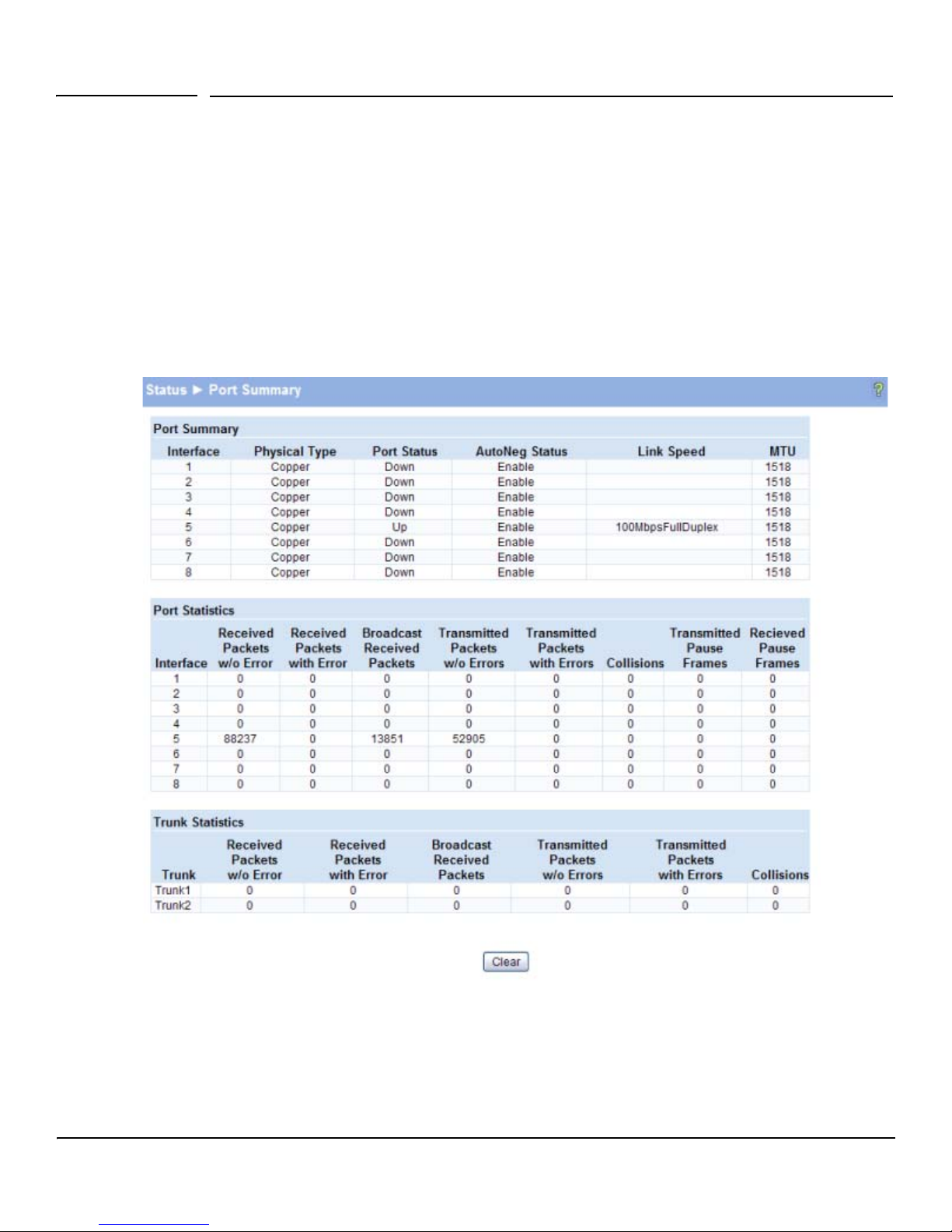
The Port Summary page displays a port summary at the top of the page and provides configuration and
status information for each port. Scroll down the page to view the Port Statistics table, which provides
per-port statistics on packets transmitted and received.
To display this page, click Status > Port Summary in the navigation pane.
A configuration summary and status of all physical and logical ports are displayed in Figure 2-3.
Figure 2-3. Port Summary Page
2-3
Page 20

Status Pages
Port Summary
Table 2-1. Port Summary Fields
Field Description
Port Summary
Interface Displays list of physical and logical interfaces supported or configured on a particular
platform.
Physical Type Displays whether the port is operating in copper mode or fiber mode.
Port Status The physical status (Up or Down) of the port.
AutoNeg Status Displays whether Auto negotiation is enabled or disabled on the port.
Link Speed The physical speed at which the port is operating.
MTU The Maximum Transmission Unit (MTU), also referred to as Max Frame size acceptable
on the specified port.
Port Statistics and Trunk Statistics
Note: The following statistics are collected for both individual port and for trunks.
Interface The list of physical and logical interfaces supported on that platform.
Received Packets w/o Error The packet count received on the port with out any packet errors.
Received Packets with Error The packet count received on the port with errors.
Broadcast Received
The packet count for Broadcast packets received on the port.
Packets
Transmitted Packets w/o
The packets transmitted out of that port with out any packet errors.
Errors
Transmitted Packets with
The number of packets transmitted out of the port with packet errors.
Errors
Collisions The count of collided packets.
Transmitted Pause Frames (For ports only) The number of Ethernet pause frames transmitted.
Received Pause Frames (For ports only) The number of Ethernet pause frames received.
■ Click Clear to reset all statistics to their initial values.
■ Click the Refresh link above the page to re-display the page with the latest port information.
For instructions on configuring port settings, see “Port Configuration” on page 4-1.
2-4
Page 21
Status Pages
LLDP Statistics
LLDP Statistics
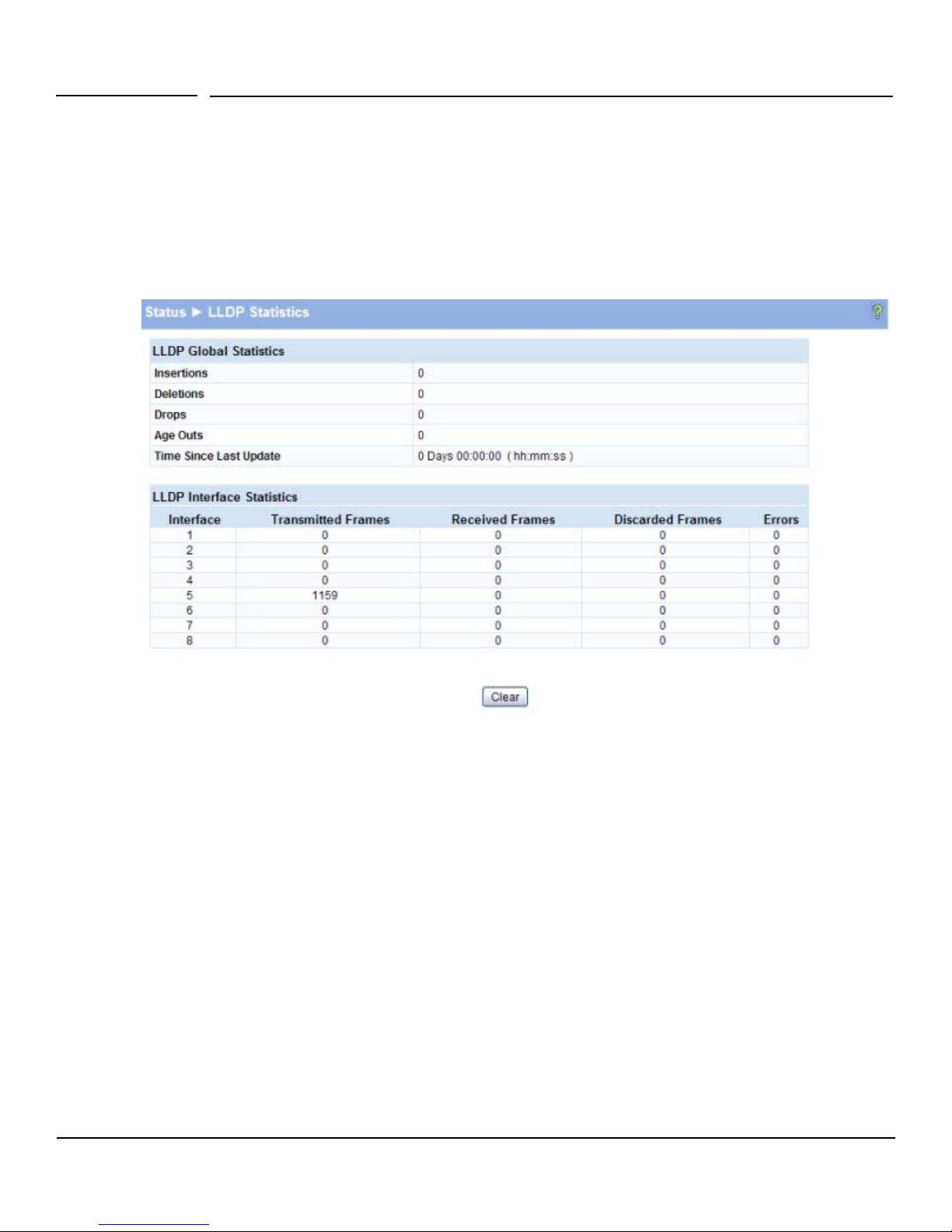
The Link Layer Discovery Protocol (LLDP) Statistics page displays summary and per-port information
for LLDP frames transmitted and received on the switch. To display this page, click Status > LLDP
Statistics in the navigation pane.
Figure 2-4. LLDP Statistics Page
2-5
Page 22

Status Pages
LLDP Statistics
Table 2-2. LLDP Statistics Page Fields
Field Description
LLDP Global Statistics
Insertions The number of times the complete set of information advertised by a particular MAC
Service Access Point (MSAP) has been inserted into tables associated with the remote
systems.
Deletions The number of times the complete set of information advertised by a particular MSAP has
been deleted from tables associated with the remote systems.
Drops The number of times the complete set of information advertised by a particular MSAP
could not be entered into tables associated with the remote systems because of
insufficient resources.
Age Outs The number of times the complete set of information advertised by a particular MAC
Service Access Point (MSAP) has been deleted from tables associated with the remote
systems because the information timeliness interval has expired.
Time Since Last Update Time when an entry was created, modified, or deleted in the tables associated with the
remote system.
LLDP Interface Statistics
Interface Interface or port number.
Transmitted Frames Number of LLDP frames transmitted on the corresponding port.
Received Frames Number of valid LLDP frames received by this LLDP agent on the corresponding port, while
the LLDP agent is enabled.
Discarded Frames Number of LLDP frames discarded for any reason by the LLDP agent on the
corresponding port.
Errors Number of invalid LLDP frames received by the LLDP agent on the
corresponding port, while the LLDP agent is enabled.
■ Click Clear to reset all statistics to their initial values.
■ Click the Refresh link above the page to re-display the page with current data from the switch.
2-6
For instructions on configuring LLDP, see “LLDP Configuration” on page 8-1.
Page 23
Status Pages
Trunk
Trunk
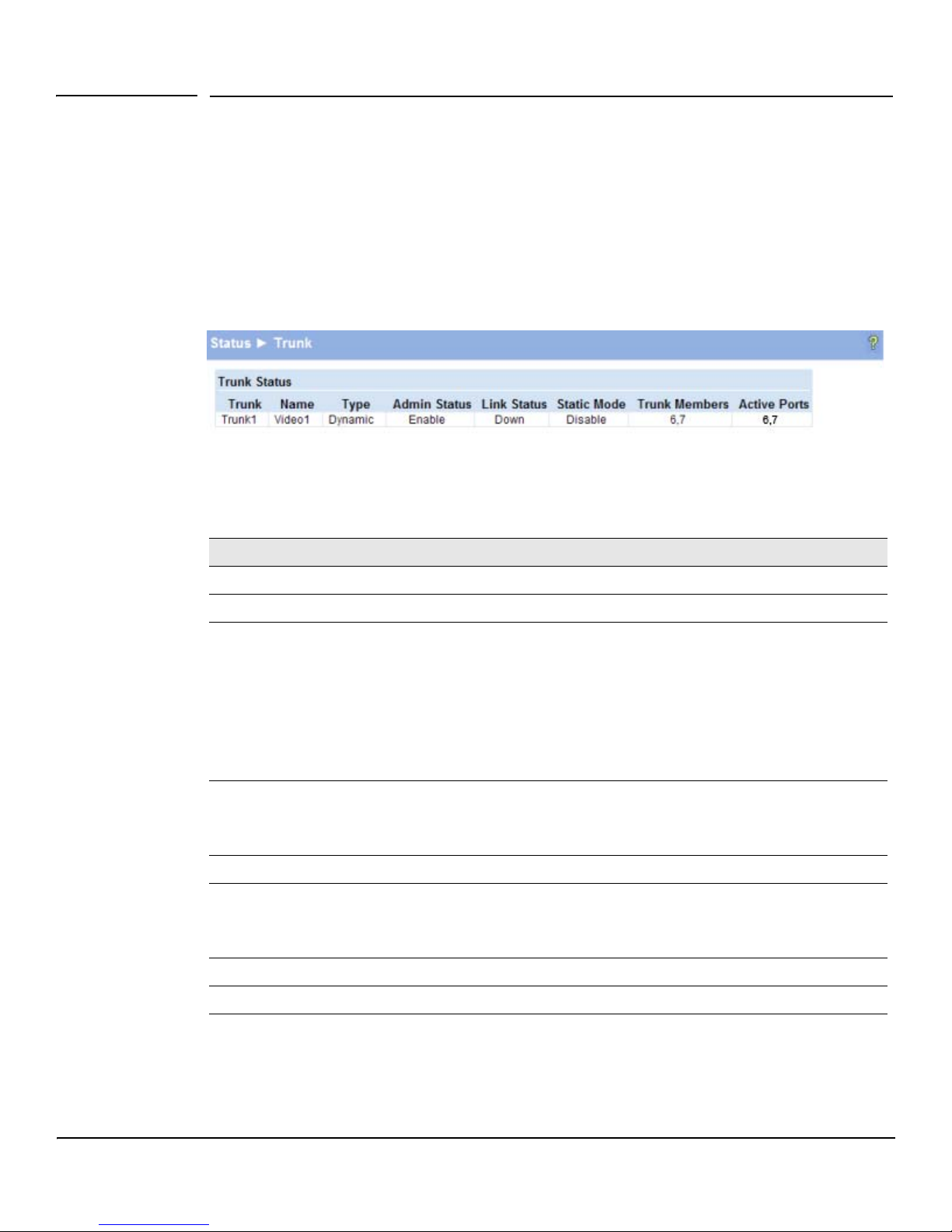
The Trunk Status page displays the configuration summary and status of each trunk. To display this
page, click Status > Trunk in the navigation pane.
Figure 2-5 displays the configuration summary and status of a trunk named Trunk1. This trunk is
configured in dynamic mode and has 3 and 5 interfaces as its active members.
Figure 2-5. Trunk Status Page
Table 2-3. Trunk Port Configuration Fields
Field Description
Tru nk An ID assigned to the trunk by the system when the trunk is created.
Name A user-created name for the trunk.
Ty pe • Indicates whether the trunk is Static or Dynamic.
• Dynamic trunks use the Link Aggregation Control Protocol (LACP, IEEE standard 802.3ad). An
LACP-enabled port automatically detects the presence of other aggregation-capable network
devices in the system and exchanges Link Aggregation Control Protocol Data Units (LACPDUs)
with links in the trunk. The PDUs contain information about each link and enable the trunk to
maintain them.
• Static trunks are assigned to a bundle by the administrator. Members do not exchange
LACPDUs. A static trunk does not require a partner system to be able to aggregate its member
ports.
Admin Status Displays whether the trunk has been enabled or disabled administratively. When disabled, no
traffic will flow. The messages that members of the trunk exchange in order to manage the trunk
(LACPDUs) will be dropped, but the links that form the Trunk will not be released. The default is
Enable.
Link Status Displays whether the link is up or down.
Static Mode Displays whether Static mode has been enabled on the trunk. When static mode is enabled, the
trunk does not transmit or process received LACPDUs. The member ports do not transmit LACPDUs
and all the LACPDUs it may receive are dropped. A static trunk does not require a partner system
to be able to aggregate its member ports.
Trunk Members List of members ports in the trunk.
Active Ports List all active member ports in the trunk.
For information on configuring trunks, see “Trunk Configuration” on page 6-1.
2-7
Page 24
Status Pages
MAC Table
MAC Table
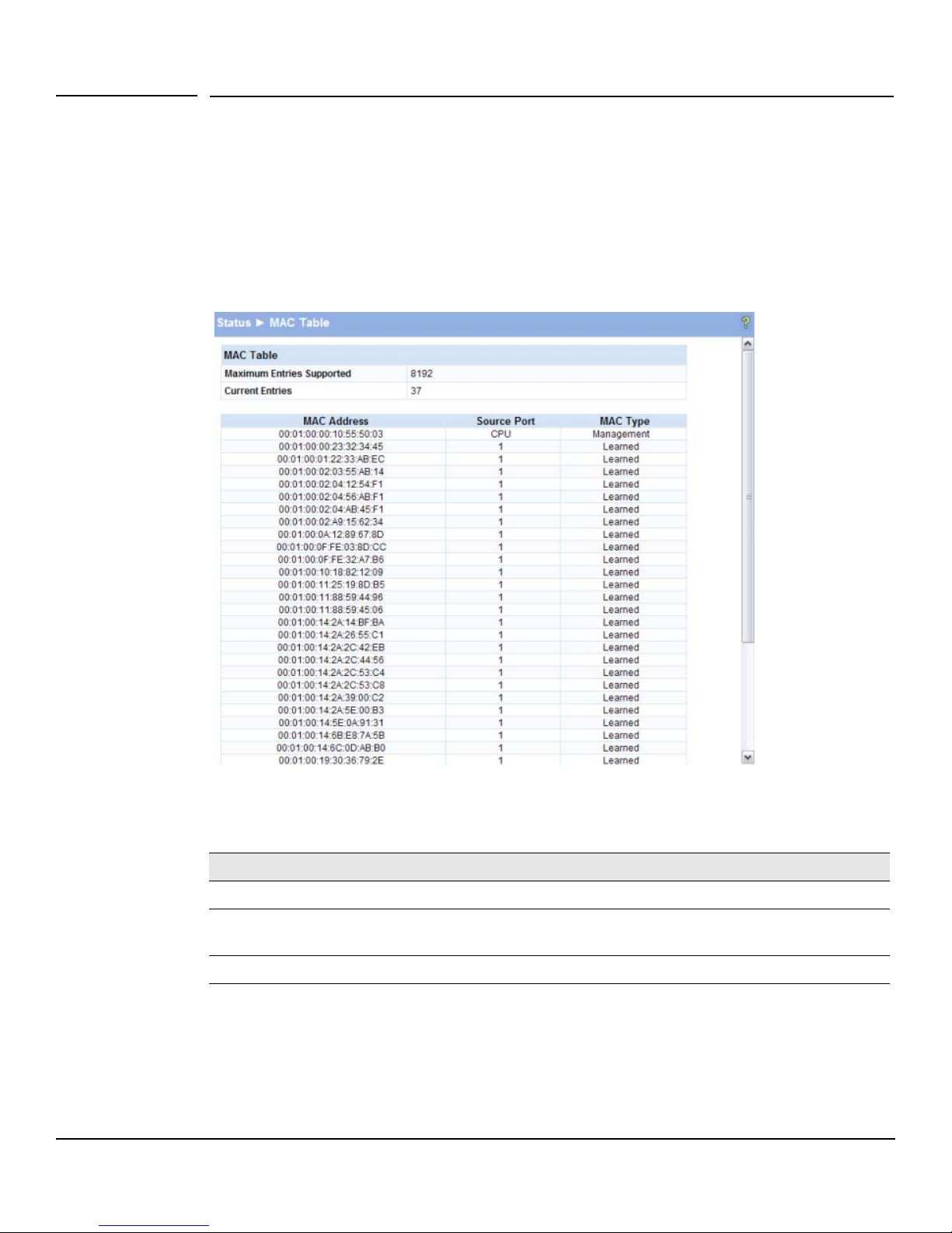
The MAC Table displays the MAC addresses associated with incoming packets on each port. Entries
are kept until they are aged-out based on the MAC Table Aging Interval, which cannot be configured
and set to 300 seconds by default.
To display the MAC Table, click Status > MAC Table in the navigation pane.
Figure 2-6. MAC Table Page
Table 2-4. MAC Table Fields
Field Description
MAC Address The list of MAC addresses learned on a particular interface.
Source Port The source interface on which the particular MAC address has been learned.
MAC Type Shows whether the MAC address is dynamically learned or whether this is a management address.
■ Click the Refresh link above the page to re-display the page with current data from the switch.
2-8
CPU is a special source port used for internal management on the switch.
Page 25
Status Pages
Loop Protection
Loop Protection
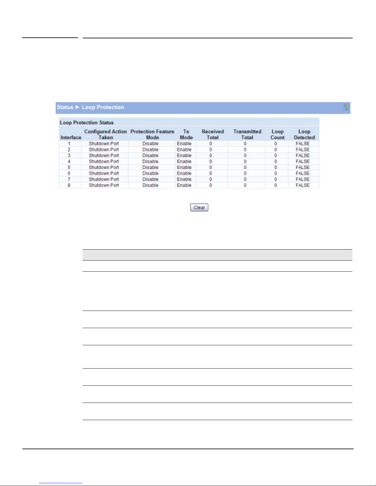
The Loop Protection status page displays the whether Loop Protection is enabled or disabled on each
port, the action to be taken, and how the feature is configured to operate on each port.
Figure 2-7. Loop Protection Page
Table 2-5. Loop Protection Fields
Field Description
Interface List of ports on the switch.
Configured Action
Tak en
Protection Feature
Mode
Tx Mode Shows whether the port is configured to forward packets to the multicast destination
Received Total The number of packets received on the interface for which the packet’s source MAC
Tra n s mitted To tal The number of packets forwarded on the interface to the multicast destination MAC
Loop Count The number of loops detected on this interface since the last system boot or since
Loop Detected Shows whether a loop has been detected on the port within the configured Shutdown
The action that is set to occur when a loop is detected on the port with Loop Protection enabled:
• Shutdown port—The port will be shut down for the configured period.
• Log—The event will be logged and the port remains operational.
• Shutdown and log— The event will be logged and the port it shut down for the configured
period.
Shows whether loop protection is enabled or disabled on the port.
MAC address designated for the Loop Protection feature.
address matches the destination multicast MAC address designated for the Loop
Protection feature.
address designated for the Loop Protection feature.
statistics were cleared.
Time.
2-9
Page 26
Status Pages
Dual Image
■ Click Clear to reset all counters to 0.
■ Click the Refresh link above the page to re-display the page with the latest status from the
switch.
For instructions on configuring this feature and a description of these fields, see “Loop Protection” on
page 4-6.
Dual Image
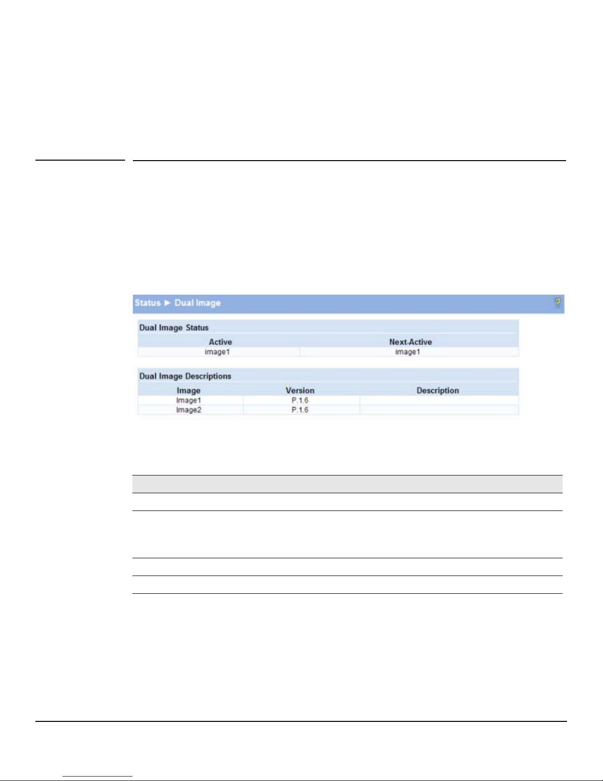
The Dual Image status page displays the status of the two system images (image1 and image2). To
display this page, click Status > Dual Image in the navigation bar.
As shown in Figure 2-8, Image1 is the Current-active image and will continue to be the Current-active
image after a reboot.
Figure 2-8. Dual Image Status Page
2-10
Table 2-6. Dual Image Status Fields
Field Description
Active The currently active image name.
Next-active The next active image name. The Administrator can configure the image to take effect
the next time the system is booted. It may be a different than the currently active image
(for example, if the administrator configures the backup image to take effect upon the
next reboot).
Image1/Image2 Version The software version of the images.
Image1/Image2 Description The configured descriptions for the images.
For instructions on configuring the active image, see “Dual Image Configuration” on page 10-9.
Page 27
Status Pages
Clock
Clock
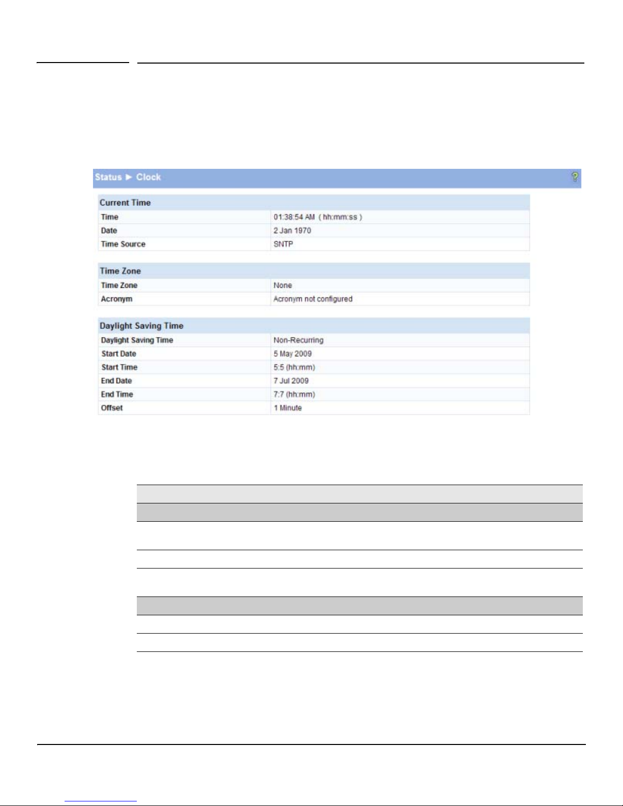
The Clock status page displays the current time, time zone, and Daylight Savings Time settings. To
display this page, click Status > Clock in the navigation bar.
Figure 2-9. Clock Status Page
Table 2-7. Clock Status Fields
Field Description
Current Time
Tim e The current time. This value is determined by an SNTP server. When SNTP is disabled, the
system time increments from 00:00:00, 1 Jan 1970, which is set at bootup.
Date The current date.
Time Source If the system time is derived from a SNTP server, then “SNTP” displays. If not, then “No time
source” displays.
Time Zone
Time Zone The time zone configured on the switch.
Acronym The acronym configured on the system for the time zone (e.g., PST, EDT).
2-11
Page 28

Status Pages
Clock
Field Description
Daylight Savings Time
Daylight Savings Time Shows whether Daylight Savings Time is enabled and the mode of operation:
• Disabled—No clock adjustment will be made for Daylight Savings Time.
• Recurring—The settings will be in effect for the upcoming period and subsequent years.
• Non-Recurring—The settings will be in effect for only one period (i.e., they will not carry
forward to subsequent years).
Start Time settings /
End Time settings
Offset The time amount of time in minutes to advance the clock during Daylight Savings Time.
Shows the following to indicate when the change to Daylight Savings time occurs and when
it ends. The fields that display here depend on which Daylight Savings Mode is configured.
• Week— The number of weeks into the month when the change to/from Daylight Savings
Time occurs. (This field is available only when the Daylight Savings Time mode is set to
Recurring.)
• Day—The day of the week when the change to/from Daylight Savings Time occurs.
• Month—Set the month when the change to/from Daylight Savings time occurs.
• Hours—Set the hour of the day when the change to/from Daylight Savings Time occurs.
• Minutes—Set the minutes in the hour when the change to/from Daylight Savings Time
occurs.
For instructions on configuring the system time, see “Simple Network Time Protocol” on page 3-3,
“Time Zone” on page 3-4, and “Daylight Savings Time” on page 3-5.
2-12
Page 29
Network Setup
You can use the Network Setup pages to configure how a management computer connects to the switch
and how the switch connects to a server to synchronize its time.
Get Connected
Use the Get Connected page to configure settings for the network interface. The network interface is
the logical interface, defined with an IP address, mask, and gateway, used for connecting a management
station to the switch via any of the switch's front-panel ports. The configuration parameters associated
with the switch's network interface do not affect the configuration of the front-panel ports through
which traffic is switched or forwarded, except that for the management port, the PVID will be the
management VLAN.
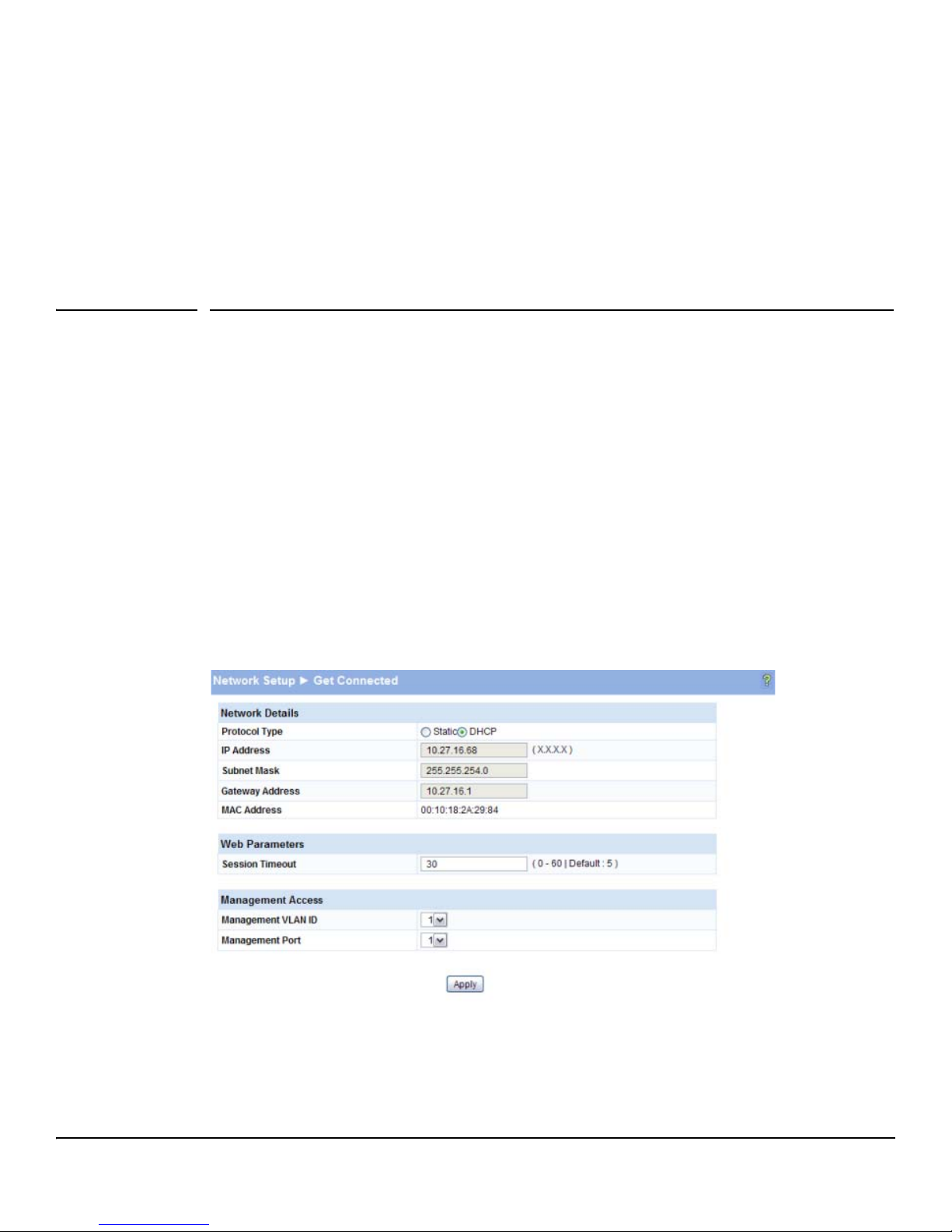
To display this page, click Network Setup > Get Connected.
3
As shown in the example configuration in Figure 3-1, the switch has been configured to acquire its IP
address through DHCP. In this example, access to the management software is restricted to members
of VLAN 1.
Figure 3-1. Get Connected Page
3-1
Page 30

Network Setup
Get Connected
Table 3-1. Get Connected Fields
Field Description
Network Details
Protocol Type Select the type of network connection:
• Static: Select this option to enable the IP address, mask, and gateway fields for data entry.
• DHCP: Select this option to enable the switch to obtain IP information from a DHCP server
on the network.
IP Address
Subnet Mask
Gateway Address
MAC Address The burned-in universally administered MAC address of this switch.
Session Timeout Specify the amount of time in minutes that a connection to the Web interface remains active,
Management VLAN ID
Management Port
■ Click Apply to save any changes for the current boot session; the changes take effect
If the protocol type is Static, enter the IP information associated with the network port. These
fields are not editable (grayed out) when DHCP is selected in the previous option.
CAUTION: Changing the protocol type or IP address discontinues the current connection;
you can log on again using the new IP information.
Web Parameters
assuming no user activity.
Management Access
Access to the management software is controlled by the assignment of a VLAN ID and the
selection of a management port. By default, the management VLAN ID is 1. Note that all ports
are members of VLAN 1 by default; the administrator may want to create a different VLAN to
assign as the management VLAN and associate it to a management port.
Any one physical port can be selected as the management port.
Note: All ports that are members of VLAN 1 (the management VLAN) will have management
access to the switch even though the management port is configured as port 1.
See “Example— Creating a Management VLAN” on page 7-5 for complete instructions on
creating a management VLAN.
immediately. Use the Maintenance > Save Configuration page to have the setting remain in effect
after a reboot.
3-2
Page 31
Simple Network Time Protocol
Network Setup
Simple Network Time Protocol
ProCurve 1810G switch software supports the Simple Network Time Protocol (SNTP). SNTP ensures
accurate network device clock time synchronization up to the millisecond. Time synchronization is
performed by a network SNTP server. The software operates only as an SNTP client and cannot provide
time services to other systems.
Note SNTP acquires the Coordinated Universal Time (UTC) from an SNTP server. Configure the Time Zone
(see page 3-4) and Daylight Savings Time (see page 3-5) to configure the offsets for your local time zone.
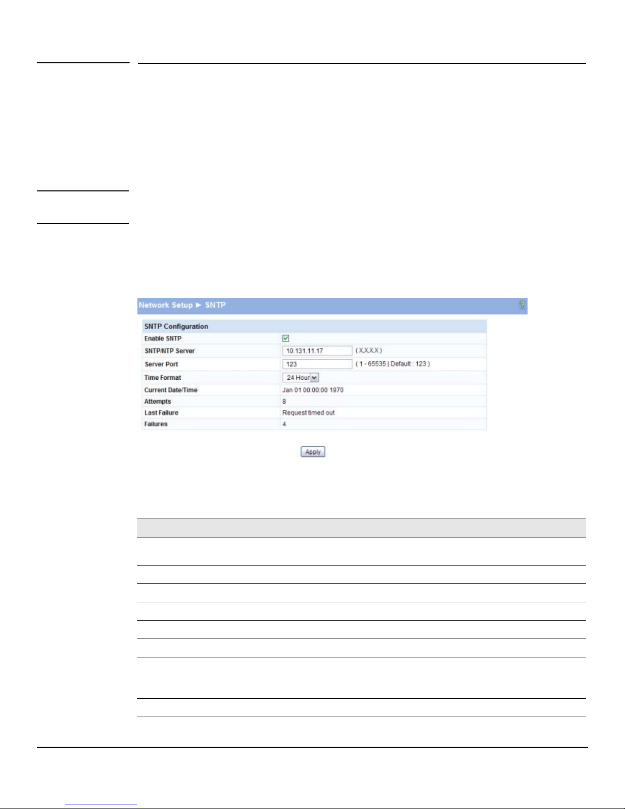
To display the SNTP page, click Network Setup > SNTP in the navigation pane.
Figure 3-2. SNTP Page
Table 3-2. SNTP Fields
Field Description
Enable SNTP Select to enable SNTP client mode. Clear to disable SNTP client mode. When disabled, the system
SNTP/NTP Server Specify the IP address of the SNTP server to send requests to.
Server Port Specify the server's UDP port to listen for responses/broadcasts (range 1–65535, default = 123).
Time Format Select either 24-hour (“military” time) format or 12-hour (standard) format.
Current Time/Date The switch-adjusted time and date when delivered by the time server.
Attempts The number of requests made to the SNTP sever since the switch was rebooted.
Last Failure The status of the last request to the SNTP server.
Failures The number of failed SNTP requests made to this server since last reboot.
time increments from 00:00:00, 1 Jan 1970, which is set at bootup.
When this value is SNTP Server Error, the server cannot send further updates. You can
reconfigure the SNTP server with a new server address to get time updates.
3-3
Page 32
Network Setup
Time Zone
■ Click Apply to save any changes for the current boot session; the changes take effect
immediately. Use the Maintenance > Save Configuration page to have the setting remain in effect
after a reboot.
■ Click the Refresh link above the page to re-display the page with current settings from the
switch.
To view a summary of clock information, click Status > Clock in the navigation pane.
Time Zone
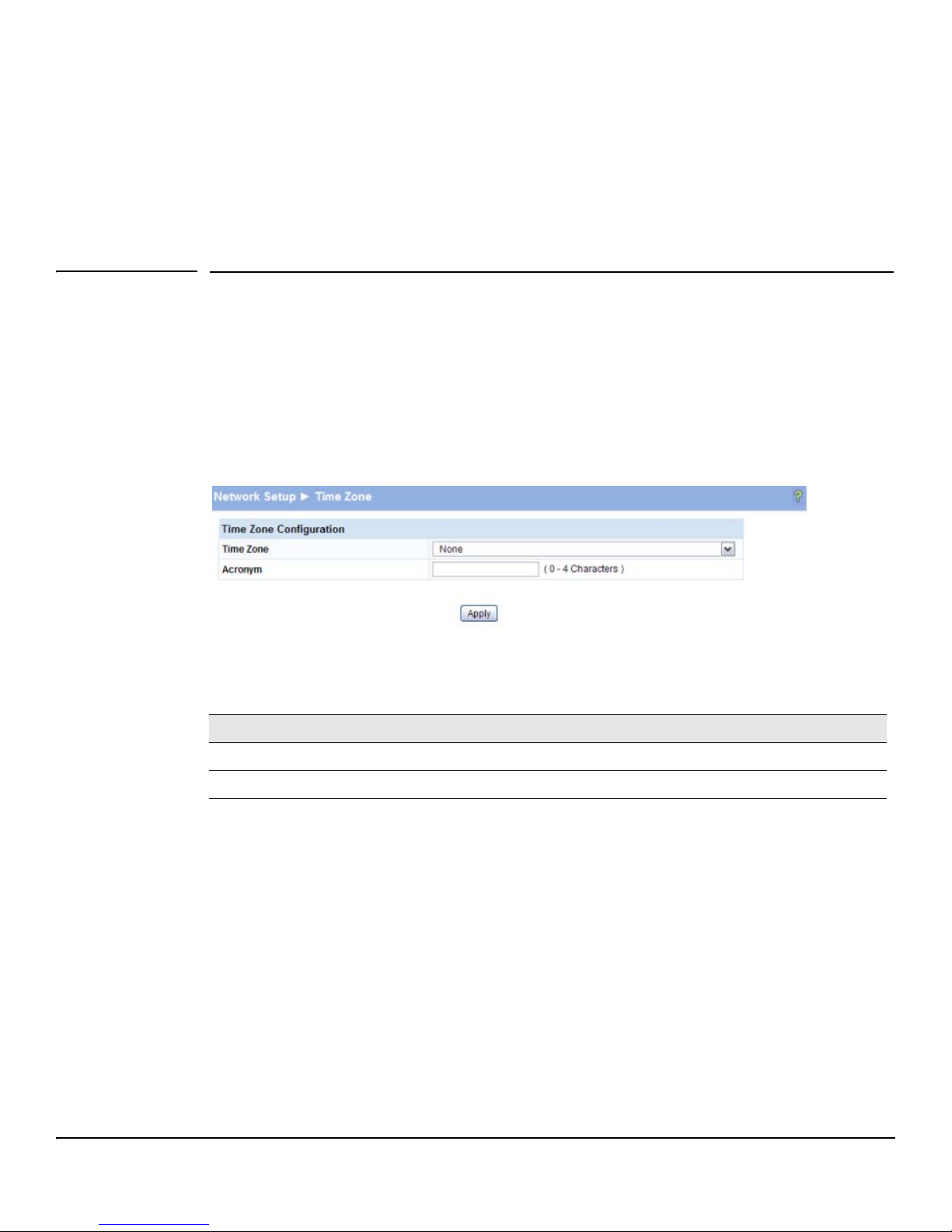
Use this page to configure your local time zone. The switch must be configured to acquire the time
from an SNTP server.
To display the Time Zone page, click Network Setup > Time Zone in the navigation pane.
Figure 3-3. Time Zone Page
Table 3-3. Time Zone Fields
Field Description
Time Zone Select the time zone for your location.
Acronym Specify an acronym for the time zone.
■ Click Apply to save any the changes for the current boot session; the changes take effect
immediately. Use the Maintenance > Save Configuration page to have the setting remain in effect
after a reboot.
■ Click the Refresh link above the page to re-display the page with current settings from the
switch.
To view a summary of clock and time zone information, click Status > Clock in the navigation pane.
3-4
Page 33
Network Setup
Daylight Savings Time
Daylight Savings Time
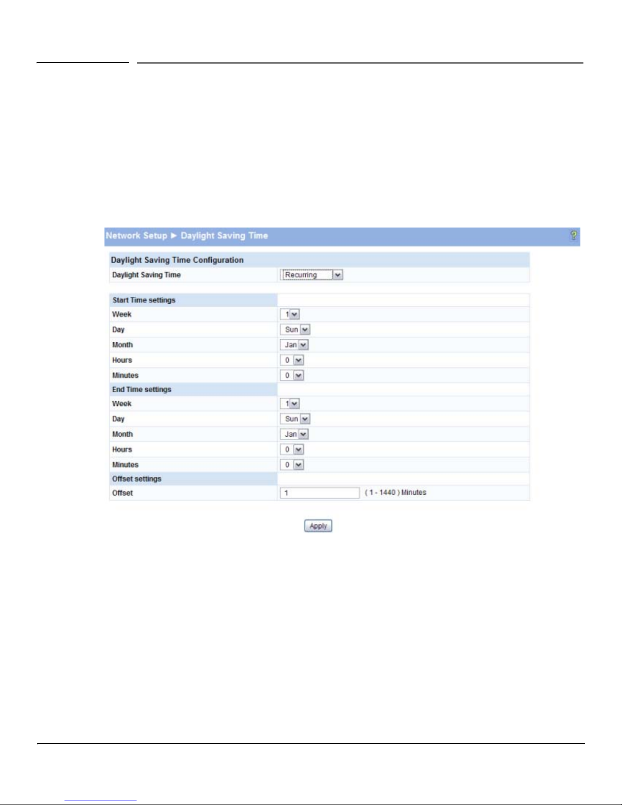
Use this page to configure if and when Daylight Savings Time (DST) occurs for your time zone. When
configured, the system time will adjust automatically during Daylight Savings Time.
To display the Time Zone page, click Network Setup > Daylight Savings Time in the navigation pane. The
page displays differently depending on the mode selected in the Daylight Savings Time field. In the
following figure, the mode is set to Recurring.
Figure 3-4. Daylight Savings Time Page
3-5
Page 34

Network Setup
Daylight Savings Time
Table 3-4. Daylight Savings Time Fields
Field Description
Daylight Savings Time Select how DST will operate:
• Disabled—No clock adjustment will be made for DST.
• Recurring—The settings will be in effect for the upcoming period and subsequent years.
• Non-Recurring—The settings will be in effect for only one period (i.e., they will not carry
forward to subsequent years).
Start Time settings /
End Time settings
Offset Specify the time amount of time in minutes to advance the clock during DST.
■ Click Apply to save any the changes for the current boot session; the changes take effect
Set the following to indicate when the change to DST occurs and when it ends.
When Recurring is selected as the DST mode, the following fields display:
• Week— The number of weeks into the month when the change to/from Daylight Savings
Time occurs.
• Day—The day of the week when the change to/from DST occurs.
• Month—Set the month when the change to/from Daylight Savings time occurs.
• Hours—Set the hour of the day when the change to/from DST occurs.
• Minutes—Set the minutes in the hour when the change to/from DST occurs.
When Non-Recurring is selected as the DST mode, the following fields display:
• Month—Set the month when the change to/from Daylight Savings time occurs.
• Date—The number of weeks into the month when the change to/from DST occurs.
• Year—Set the year in which these settings will take effect.
• Hours—Set the hour of the day when the change to/from DST occurs.
• Minutes—Set the minutes in the hour when the change to/from DST occurs.
immediately. Use the Maintenance > Save Configuration page to have the setting remain in effect
after a reboot.
■ Click the Refresh link above the page to re-display the page with current settings from the
switch.
To view a summary of clock and DST information, click Status > Clock in the navigation pane.
3-6
Page 35
Switching Pages
You can use the Switching Pages to configure port operation and capabilities.
Port Configuration
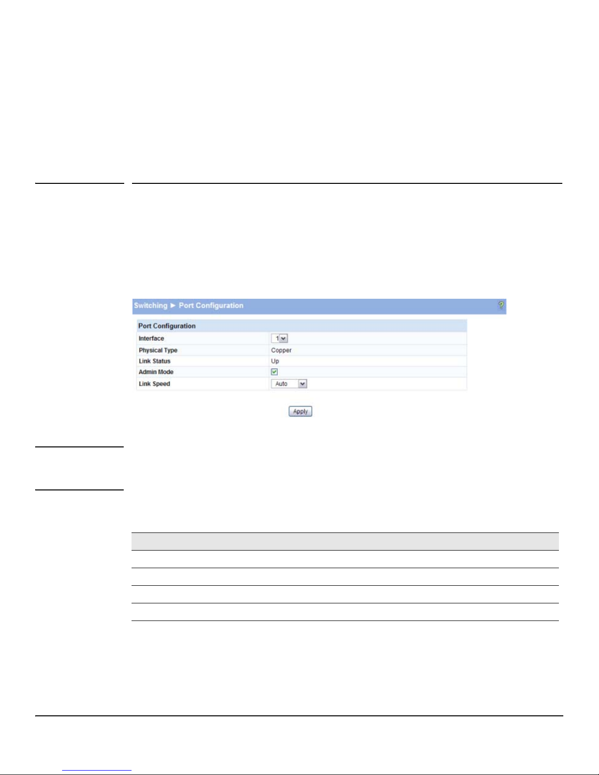
Use the Port Configuration page to view and configure parameters for port operation. To access this
page, click
Figure 4-1. Port Configuration Page
4
Switching > Port Configuration in the navigation pane.
Note The display and the content of this page changes based on the physical port selected. For example, if
the selected port is an optional copper/fiber port and fiber is being used, than the Link Speed selections
will display only valid options for that port.
Table 4-1. Port Configuration Fields
Field Description
Interface Select the interface to configure.
Physical Type Describes the port type (i.e., Copper or Fiber).
Link Status Displays Up or Down to indicate operational status.
Admin Mode Select to enable access to the port on the network. Clear to disable the port.
4-1
Page 36
Switching Pages
Jumbo Frames
Field Description
Link Speed Configure the duplex mode and transmission rate for the selected port. (These options may change
■ Click Apply to save any changes for the current boot session; the changes take effect
immediately. Use the
depending on the port type.)
• Auto—The rates and duplex mode will be auto-negotiated.
• 10HDX—10Mbps, half-duplex
• 10FDX—10Mbps, full-duplex
• 100HDX—100Mbps, half-duplex
• 100FDX—100Mbps, full-duplex
• 1000FDX— 1000Mbps, full duplex (for fiber ports)
Note: The port's maximum capability is advertised.
Maintenance > Save Configuration page to have the setting remain in effect
after a reboot.
To view a summary of port information, click
Status > Port Summary in the navigation pane.
Jumbo Frames
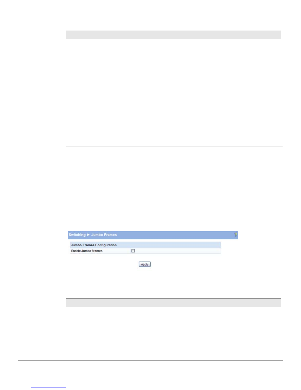
Use the Jumbo Frames page to enable the switch to forward jumbo Ethernet frames. The jumbo frames
feature extends the standard Ethernet Maximum Transmission Unit (MTU) from 1518 bytes (1522 bytes
with a VLAN header) to 9216 bytes. If it is enabled, any device connecting to the same broadcast domain
should also support jumbo frames.
This feature is disabled by default.
To access this page, click Switching > Jumbo Frames in the navigation pane.
Figure 4-2. Jumbo Frames Page
Table 4-2. Jumbo Frames Fields
Field Description
Enable Jumbo Frames Select to enable the switch to forward jumbo frames up to 9216 bytes.
■ Click Apply to save any changes for the current boot session; the changes take effect
immediately. Use the Maintenance > Save Configuration page to have the setting remain in effect
after a reboot.
4-2
Page 37
Switching Pages
Port Mirroring
Port Mirroring
Port mirroring sends a copy of all packets sent and/or received on one port (the source port) to another
port (the destination port) for monitoring and analysis by an external network analyzer. Multiple switch
ports can be configured as source ports, with each port mirrored to the same destination. You can also
mirror the internal CPU traffic to an external port for debugging the CPU.
CAUTION ■ When configuring port mirroring, avoid oversubscribing the destination port to
prevent the loss of mirrored data.
■ While a port is used as the destination port for mirrored data, the port cannot be
used for any other purpose; the port will not receive and forward traffic.
To display this page, click Switching > Port Mirroring in the navigation pane.
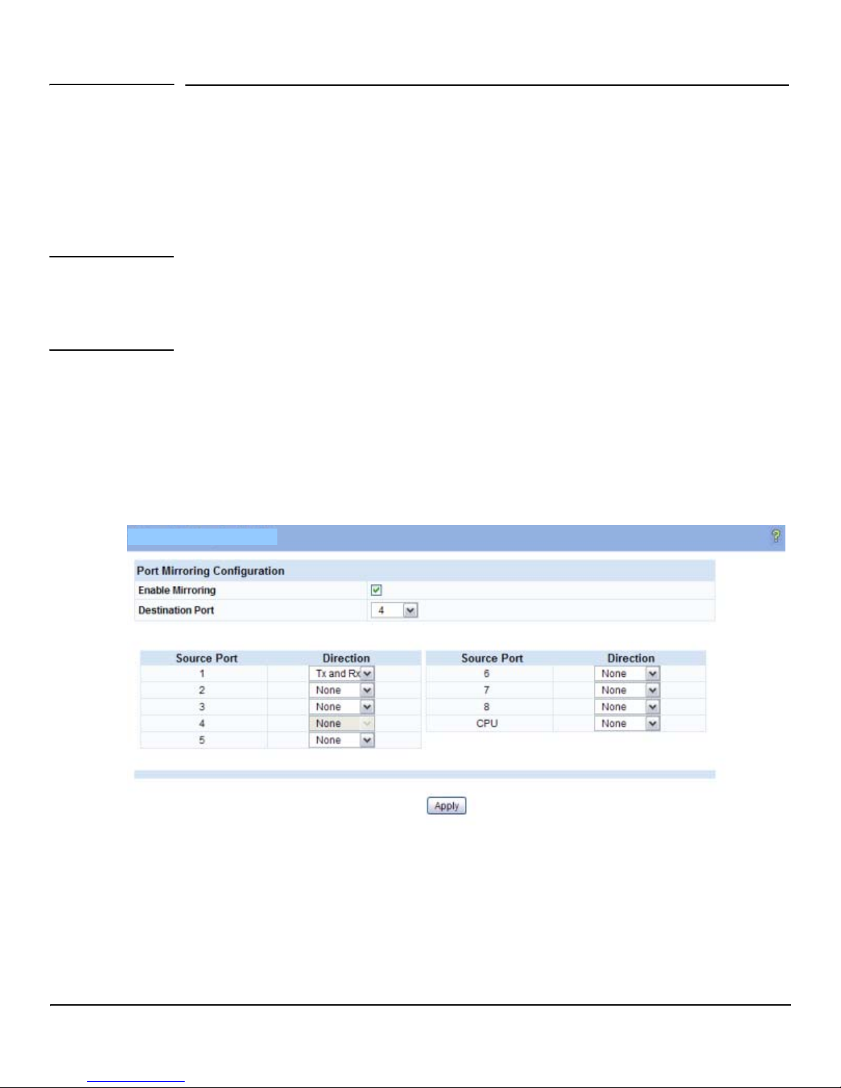
In the example configuration in Figure 4-3, port mirroring is configured to mirror TX and RX packets
on Source Port 1 to Destination Port 4.
Figure 4-3. Port Mirroring Page
4-3
Page 38
Switching Pages
Flow Control
Table 4-3. Port Mirroring Fields
Field Description
Enable Mirroring Select to enable port mirroring capability globally on the switch. Clear to disable the feature.
Destination Port Select the port to which packets will be mirrored.
Source Port
Direction
■ Click Apply to save any changes for the current boot session; the changes take effect
For each source port you want to mirror to the destination port, select the direction of the packets
to be mirrored:
• Tx and Rx— All packets transmitted and received on the source port are mirrored.
• Rx— Only packets received on the source port are mirrored.
• Tx— Only packets transmitted on the source port are mirrored.
• None— No packets are mirrored from this port (default).
The port selected as the Destination Port is greyed-out and unavailable for selection.
Note: The Source Port CPU can be mirrored to an external port to debug traffic to and from the
CPU.
immediately. Use the Maintenance > Save Configuration page to have the settings remain in effect
after a reboot.
Flow Control
When a port becomes oversubscribed, it may begin dropping all traffic for small bursts of time during
the congestion condition. This can lead to high-priority and/or network control traffic loss. When 802.3x
flow control is enabled, a lower-speed switch can communicate with a higher-speed switch by
requesting that the higher-speed switch refrain from sending packets. Transmissions are temporarily
halted to prevent buffer overflows.
Note Flow control works well on when the Link Speed is auto-negotiated.
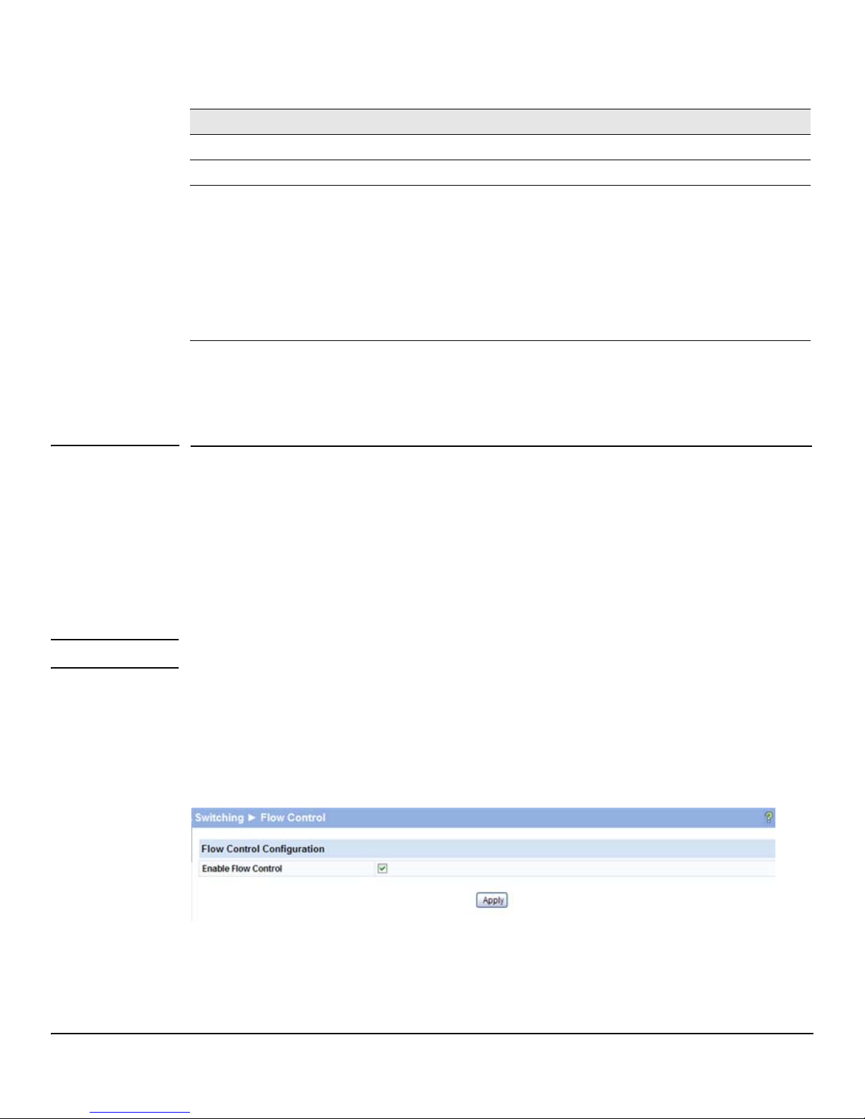
Use the Flow Control page to enable or disable this functionality. To access the page, click
Switching > Flow Control in the navigation pane. As shown in the example configuration in Figure 4-4,
flow control is enabled globally, which would enable flow control on all the ports in the switch.
Figure 4-4. Flow Control Page
4-4
Page 39
Switching Pages
Green Features
Table 4-4. Flow Control Fields
Field Description
Enable Flow Control Select to enable flow control on the switch. Clear to disable the feature.
■ Click Apply to save any changes for the current boot session; the changes take effect
immediately. Use the Maintenance > Save Configuratio n page to have the settings remain in effect
after a reboot.
Green Features
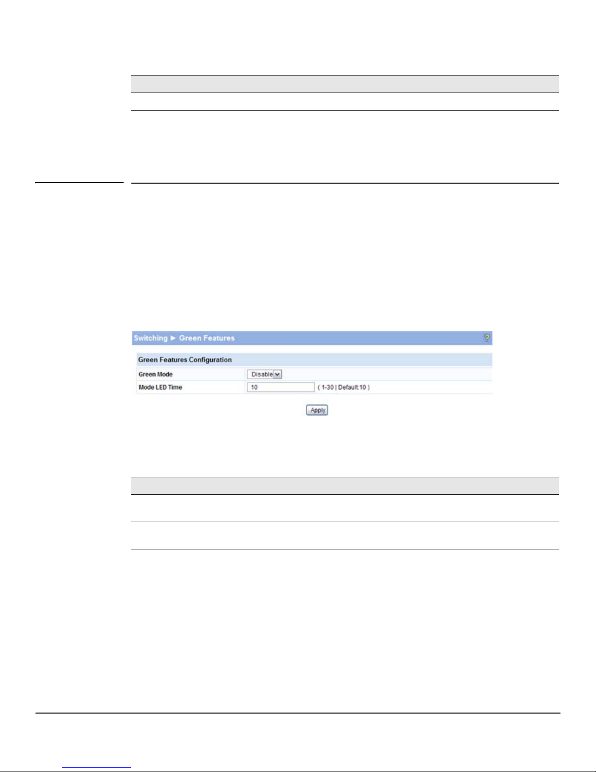
ProCurve 1810G switch software allows user to enable or disable Green Mode. When enabled, LEDs
on the switch are turned off. In Green Mode, the switch consumes less power than in normal highperformance mode.
To configure Green Mode, click Switching > Green Features in the navigation pane.
Figure 4-5. Green Features
Table 4-5. Green Mode Fields
Field Description
Green Mode Enable or disable Green Mode on the switch. When Green Mode is enabled, LEDs on the switch
are turned off. In addition, port transceivers that do not detect a link are placed in low-power mode.
Mode LED Time Specify the time in minutes that port LEDs illuminate if the LED Mode button is pressed while the
switch is in Green Mode.
■ Click Apply to save any changes for the current boot session; the changes take effect
immediately. Use the Maintenance > Save Configuratio n page to have the settings remain in effect
after a reboot.
4-5
Page 40
Switching Pages
Loop Protection
Loop Protection
Loops in a network can consume switch resources and degrade performance. Detecting loops manually
can be very cumbersome and time consuming. ProCurve 1810G switch software provides an automatic
Loop Protection feature.
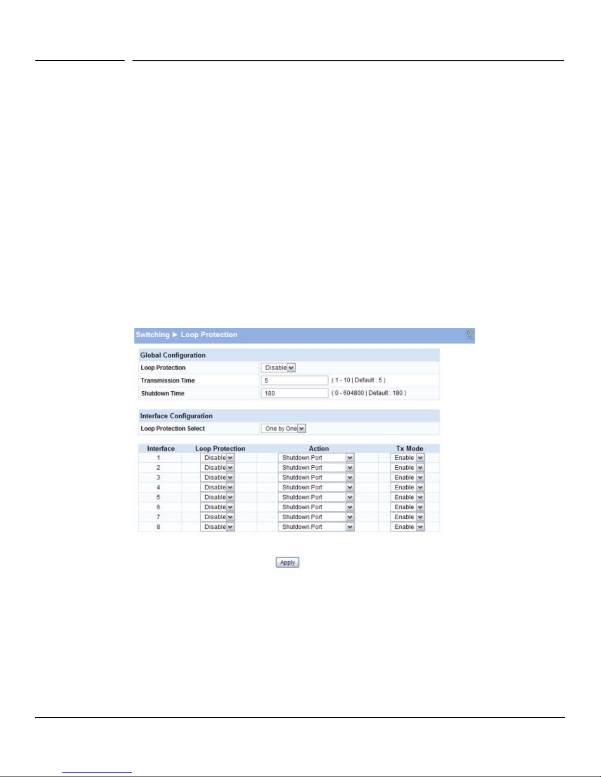
Loop Protection may be enabled or disabled globally and on a port-by-port basis. When enabled globally,
the software sends loop protection packets to a reserved layer 2 multicast destination address on all
the ports on which the feature is enabled. Transmission of the packet can be disabled selectively on
certain ports, even when Loop Protection is enabled.
If this multicast packet comes back to the switch with any of the ports’ MAC addresses as the source,
the switch determines that a loop has occurred. The port that received the loop protection packet from
the switch can be shut down for a configured period, or a log entry can be made.
Ports on which Loop Protection is disabled drop the loop protection packets silently.
To configure Loop Protection, click Switching > Loop Protection in the navigation pane.
Figure 4-6. Loop Protection
4-6
Page 41

Switching Pages
Loop Protection
Table 4-6. Loop Protection Fields“
Field Description
Loop Protection Select to enable globally enable this feature.
Transmission Time Enter the time interval, in seconds, between sending Loop Protection packets.
Shutdown Time Set the number of seconds that a port remains shut down if a loop has been detected on the
port.
Loop Protection Select Select how you want to configure Loop Protection:
• All—Enables all interfaces with Loop Protection.
• One by One—Enables you to configure Loop Protection on ports individually (default).
• None—Disables Loop Protection on all interfaces.
Interface / Loop
Protection
Action If Loop Protection is enabled on a port, select one of the following actions to occur when a
Tx Mode If Loop Protection is enabled on a port, select Enable to allow the port to forward packets to
■ Click Apply to save any changes for the current boot session; the changes take effect
Select Enable for each port on which you want to use this feature.
loop is detected:
• Log—The event is logged and the port remains operational.
• Shutdown port—The port is shut down for the configured period.
• Log and Shutdown Port—The event is logged and the port it shut down for the configured
period.
the multicast destination MAC address designated for the Loop Protection feature. Select
Disable to disallow forwarding.
immediately. Use the Maintenance > Save Configuratio n page to have the settings remain in effect
after a reboot.
To view a summary of how this feature is configured on each port, click Status > Loop Protection
in the navigation pane.
4-7
Page 42

Switching Pages
Loop Protection
4-8
Page 43
Security
5
HP ProCurve 1810G switch software includes a robust set of built-in denial-of-service (DoS) and stormcontrol protections, and allows configuring secure HTTP (HTTPS) management sessions.
Advanced Security
HP ProCurve 1810G switch software provides the following built-in security features:
■ Denial of Service (DoS) protections— A DoS attack is an attempt to saturate the switch with
external communication requests to prevent the switch from performing efficiently, or at all.
You can enable DoS protection that prevents common types of DoS attacks.
CAUTION The DoS feature does not generate any notifications (such as error messages, syslog
messages, SNMP traps) if a DoS attack occurs.
■ Storm Control— This feature protects against condition where incoming packets flood the
LAN, causing network performance degradation. The software includes Storm Control
protection for broadcast and multicast traffic (unicast frames are not affected). If the rate of
incoming traffic on an interface increases beyond the threshold (5% of the port speed), the
traffic is dropped.
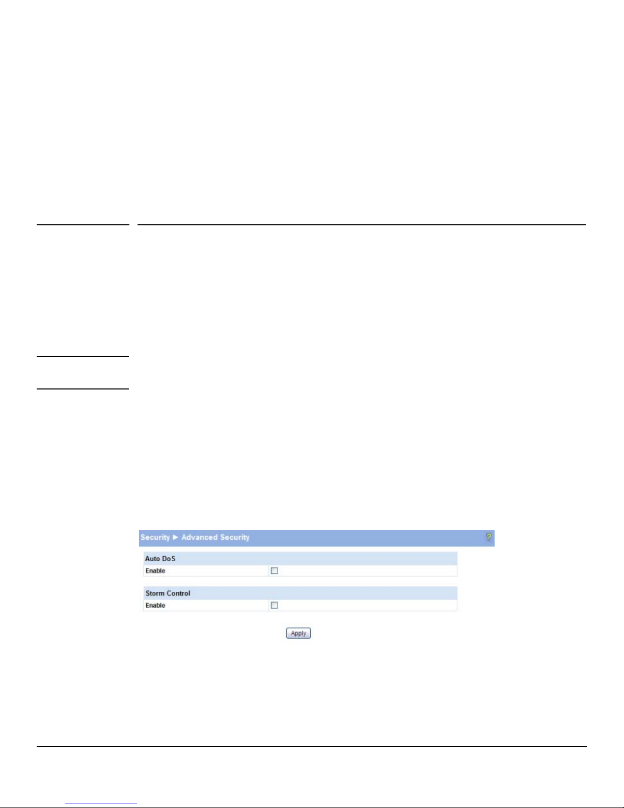
To display the Advanced Security page, click Security > Advanced Security in the navigation pane.
Figure 5-1. Advanced Security Page
5-1
Page 44

Security
Secure Connection
Table 5-1. Advanced Security Fields
Field Description
Auto DoS Select Enable to enable the following protections, or clear to disable all protections.
• Prevent Land Attack—Prevents receiving packets with same source and destination IP
addresses.
• Prevent PingOfDeath Attack—Prevents receiving ping packets with a size larger than 512 bytes
through the use of fragments, which can target vulnerable systems.
• Prevent InvalidTCPFlags Attack—Prevents receiving packets with invalid TCP flags:
– TCP Flag SYN set and Source Port less than 1024
– TCP Control Flags = 0 and TCP Sequence Number = 0
– TCP Flags FIN, URG, and PSH set and TCP Sequence Number = 0
– TCP Flags SYN and FIN set
• Prevent PingFlood Attack—Prevents Ping Flood by limiting the number of ICMP Ping packets.
The rate is 1000 ICMP packets per second.
Storm Control Select Enable to activate Storm Control protection for broadcast and multicast globally in the
■ Click Apply to save any changes for the current boot session; the changes take effect
system. The threshold is 5% of the port speed; i.e., only 5% of the traffic will be received. Clear to
not use the Storm Control feature.
immediately. Use the Maintenance > Save Configuration page to have the settings remain in effect
after a reboot.
Secure Connection
HP ProCurve 1810G switch software allows the administrator to enable or disable Secure HTTP
protocol (HTTPS). When enabled, the administrator can establish a secure connection with the switch
using the Secure Sockets Layer (SSL) protocol. Secure HTTP can help ensure that communication
between the management system and the switch is protected from eavesdropping and man-in-themiddle attacks. The HP ProCurve 1810G switch software supports SSL version 3.0.
SSL enables the switch to generate and store a certificate that functions as a digital passport, enabling
client Web browsers to verify the identity of the switch before accessing it.
Note SSL is described in client/server terminology, where the SSL-enabled switch is the server and a Web
browser is the client.
The certificate provides information to the browser such as the server name, the trusted certificate
authority (CA) that issued the certificate, the date it was issued, and the switch’s public key.
The browser and server use this information negotiate a secure connection in the following manner:
■ The browser verifies the certificate authority’s authenticity by checking it against its own list
of CAs. (Web browsers such as Microsoft Internet Explorer and Mozilla Firefox maintain data
on trusted CAs.)
5-2
Page 45
Secure Connection
■ After validating the CA, the browser and switch negotiate the highest level of security available
Security
to both. The browser uses the public key to encrypt a random number and send it to the switch.
The switch uses a private key stored in memory (not advertised on the certificate) to decrypt
it. From this process, the browser and switch determine an algorithm for encrypting and
decrypting all further communication during the HTTPS session.
To enable secure HTTPS connections via SSL, the HTTPS Admin mode must be enabled on the switch,
and the Web server must have a public key certificate. The switch can generate its own certificates, or
you can generate these externally and download them to the switch.
■ Certificates generated by the switch are self-signed; that is., the validity of the information
provided in the certificate is attested to by the switch itself.
■ Downloaded certificates can also be self-signed (by a server other than the switch), or they
can be root certificates. A root certificate has been digitally signed by a CA, and is therefore
considered to provide a higher level of security.
You can also download the encryption parameter files that provide algorithms for encrypting the key
exchanges.
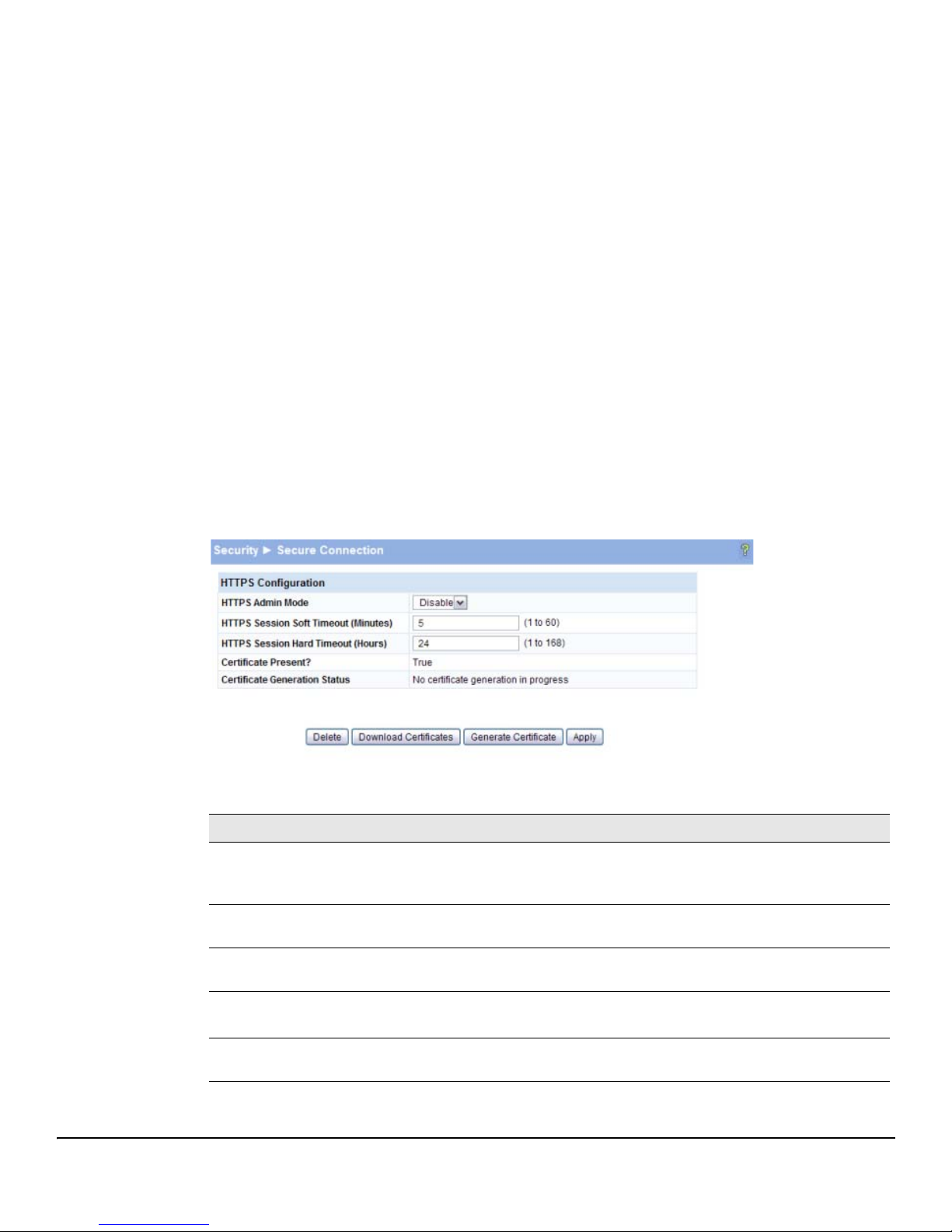
To manage HTTP parameters and certificates, you use both the Secure Connection page and the Update
Manager page. To display the Secure Connection page, click Security > Secure Connection in the
navigation pane.
Figure 5-2. Secure Connection
Table 5-2. Secure Connection Fields
Field Description
HTTPS Admin Mode Select Enable to allow secure HTTPS sessions. (Verify that the Certificate Present
field is set to Tru e.)
Select Disable to prevent HTTPS sessions, even if a certificate is present.
Session Soft Timeout Specify the number of minutes after which an HTTPS session times-out if there is no
user activity.
Session Hard Timeout Specify the number of minutes after which an HTTPS session times-out, regardless
of recent user activity.
Certificate Present? True—A certificate is available for use with HTTPS sessions.
Certificate Generation Status Indicates that a certificate is being generated or that no certificate generation is in
False— No certificate is available on the switch.
progress.
5-3
Page 46
Security
Secure Connection
■ If the value of the Certificate Present? field is True, you can click Delete to delete the existing
certificate.
■ If you click Download Certificates, the Update Manager page will be displayed to enable you to
download a certificate file to the switch. See “Downloading SSL Certificates and Diffie-Hellman
Files” on page 5-4.
■ If you click Generate Certificates, the switch creates its own self-signed public key certificate.
See “Generating Certificates” on page 5-5.
■ If you enable or disable HTTPS Admin Mode, or change the timeout settings, click Apply to
save the changes for the current boot session; the changes take effect immediately. Use the
Maintenance > Save Configuration page to have the settings remain in effect after a reboot.
Note It is advisable to download or regenerate a certificate when the previous certificate has expired, or
when you have reason to suspect that security has been breached and the certificate has been taken
for use by another server.
See the following sections for instructions on downloading and generating certificates.
Downloading SSL Certificates and Diffie-Hellman Files
You can use the Update Manager page to download a public key certificate that has been signed by
another server, or a root certificate that has been signed by a certificate authority. You can also
download Diffie-Hellman (DH) encryption parameter files, which establish the algorithms for encrypting key exchanges.
Before you download a file to the switch, the following conditions must be true:
■ The file to download is on the server in the appropriate directory.
■ The file is in the correct format.
■ The switch has a path to the server.
Use the following procedures to download an SSL certificate or DH files.
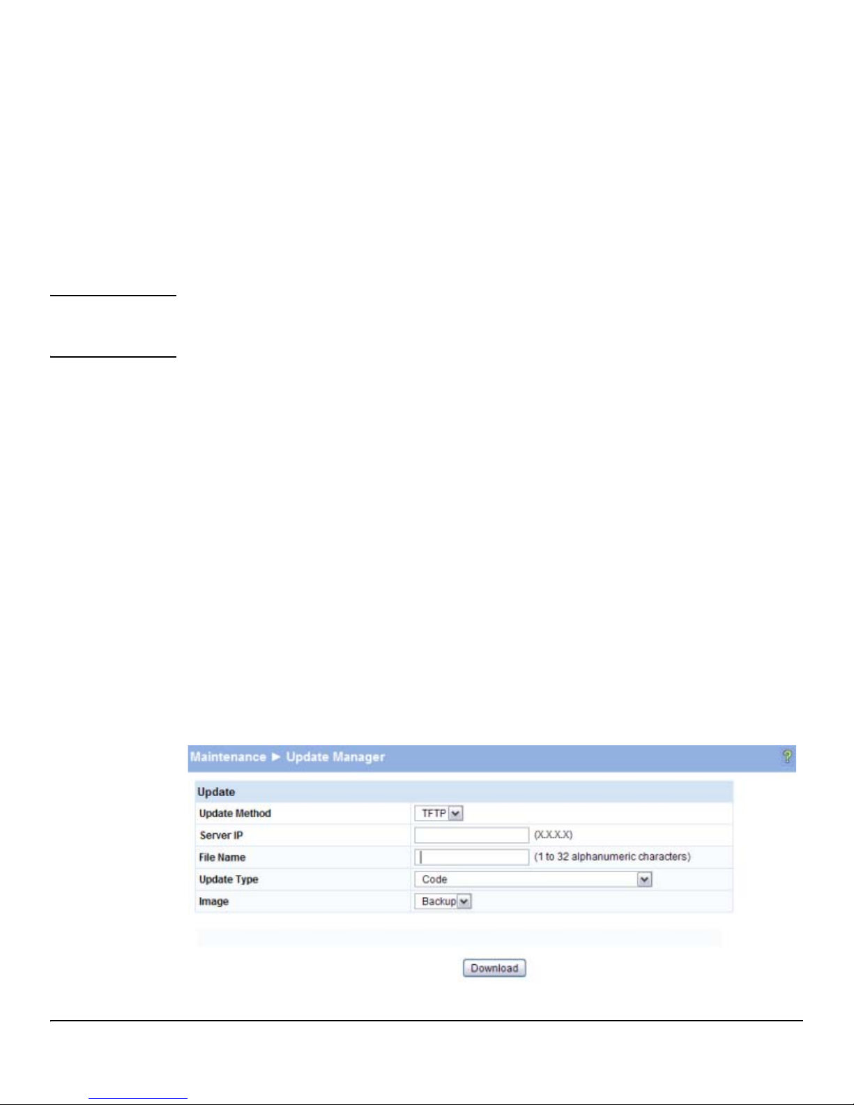
1. Click Download Certificates.
The Update Manager page displays.
Figure 5-3. Using Update Manager to Download Certificates
5-4
Page 47

Secure Connection
2. Select the protocol to use, based on the server type that the certificate is stored on: TFTP or HTTP.
3. For an HTTP upload, browse for the file on your local computer or network.
For a TFTP upload, enter the Server IP address, and specify the File Name (full path without the
server IP address).
4. From the Update Type field on the File Download page, select one of the following:
• SSL Trusted Root Certificate PEM File: SSL Trusted Root Certificate File (PEM Encoded)—An
SSL certificate that has been digitally signed by a certificate authority.
• SSL Server Certificate PEM File: SSL Server Certificate File (PEM Encoded)— An SSL certificate
that has been signed by another server.
• SSL DH Weak Encryption Parameter PEM File or SSL DH Strong Encryption Parameter PEM File —
These can be downloaded from a TFTP server only. DH certificates provide the algorithms for
encrypting key exchanges and are used independent of the certificate. The weak version uses
a cipher strength of 512 bits and the strong version uses a cypher strength of 1024 bits. Browser
settings determine which DH file parameters are requested at the start of the SSL session.
5. Click Download.
To view that status of the update, you can view the Status > Log page.
Security
6. To return to the Secure HTTP Configuration page, click Security > Secure Connection in the
navigation pane.
7. To enable the HTTPS admin mode, select Enable from the HTTPS Admin Mode field, and then click
Apply.
Generating Certificates
To have the switch generate the certificates:
1. Click Generate Certificates.
The page refreshes with the message “Certificate has been generated.”
2. Click Apply to complete the process.
When complete, the page refreshes with the message “No certificate generation in progress” and
the Certificate Present field displays as Tr ue .
Note When a certificate is present a Delete button appears to enable deleting the certificate.
5-5
Page 48

Security
Secure Connection
5-6
Page 49

Trunks
6
Trunks allow for the aggregation of multiple full-duplex Ethernet links into a single logical link. Network
devices treat the aggregation as if it were a single link, which increases fault tolerance and provides
load sharing capability. You assign the trunk VLAN membership after a trunk is created.
A trunk interface can be either static or dynamic, but not both.
■ Dynamic trunks use the Link Aggregation Control Protocol (LACP, IEEE standard 802.3ad).
An LACP-enabled port automatically detects the presence of other aggregation-capable
network devices in the system and exchanges Link Aggregation Control Protocol Data Units
(LACPDUs) with links in the trunk. The PDUs contain information about each link and enable
the trunk to maintain them.
■ Static trunks are assigned to a bundle by the administrator. Members do not exchange
LACPDUs. A static trunk does not require a partner system to be able to aggregate its member
ports.
All members of a trunk must be either static or dynamic.
Note If the maximum number of trunks that the platform supports are configured, additional trunks are not
allowed.
Trunk Configuration
Use the Trunk Configuration page to create one or more full duplex Ethernet links to be aggregated
together.
■ A trunk can aggregate up to four physical ports.
■ On HP ProCurve 1810G-24 switches, up to eight trunks can be created.
■ On HP ProCurve 1810G-8 switches, up to four trunks can be created.
After you create the trunk, it appears in a list at the bottom of the page where you can modify its
properties or delete it. Use the Trunk Membership page to assign ports to the trunk.
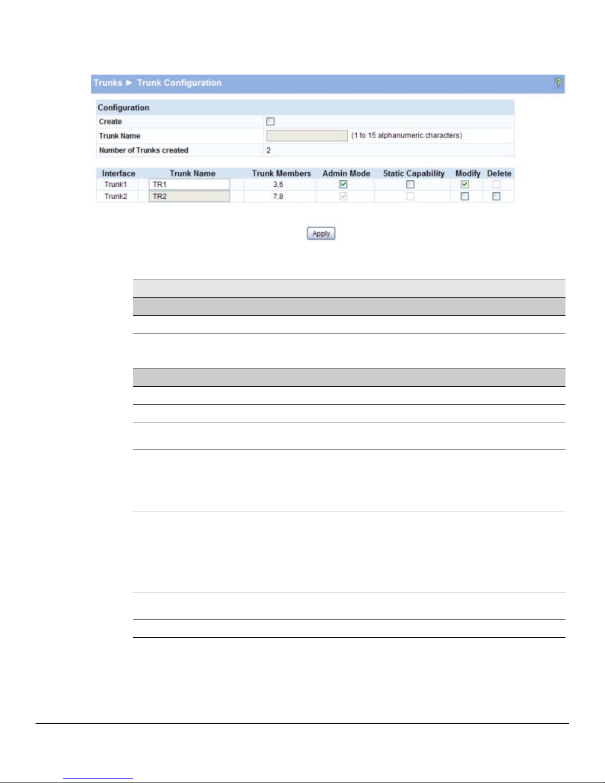
To access the Trunk Configuration page, click Trunk > Trunk Configuration in the navigation pane.
As shown in the example configuration in Figure 6-1, two trunks named TR1 and TR2 have already
been created.
6-1
Page 50
Trunks
Trunk Configuration
Figure 6-1. Trunk Configuration Page
Table 6-1. Trunk Configuration Fields
Field Description
Configuration
Create Select to enable the fields for creating a new trunk.
Trunk Name Specify a name for the trunk.
Number of Trunks created The number of trunks created. The maximum number of trunks is platform-dependent.
Trunk List
Interface The interface number for the trunk. Interface numbers are assigned sequentially.
Trunk Name The name of the trunk. You can select Modify to change the name of a trunk.
Trunk Members The ports assigned to the trunk. Use the Trunk Membership page to assign ports to the
trunk.
Admin Mode The administrative mode of the port (enabled or disabled). Newly created trunks are up
by default.
When disabled, no traffic will flow and LACPDUs will be dropped, but the links that form
the Trunk will not be released.
To change this setting, select Modify, select or clear Admin Mode, then click Apply.
Static Capability When enabled, the trunk does not transmit or process received LACPDUs. The member
ports do not transmit LACPDUs and all the LACPDUs it may receive are dropped. A static
trunk does not require a partner system to be able to aggregate its member ports.
When disabled, the interface will automatically be configured in dynamic mode. In
dynamic mode, the interface transmits and processes LACPDUs and requires a partner
system.
To change this setting, select Modify, select or clear Static Capability, then click Apply.
Modify Select this box to enable modifying the Static Capability or Admin Mode settings. Click
Apply if you change any settings.
Delete Select this box and click Apply to delete the trunk.
■ Click Apply if you create a new Trunk or modify any existing trunk settings. Use the Maintenance
> Save Configuration page to have the setting remain in effect after a reboot.
6-2
Page 51
Trunk Membership
Trunks
Trunk Membership
Use this page to specify the switch ports that are included in each trunk. To access the page, click
Trunk > Trunk Membership in the navigation pane.
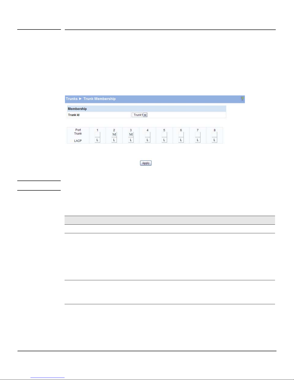
As shown in the example configuration in Figure 6-2, ports 2 and 3 have been added to Trunk1.
Figure 6-2. Trunk Membership Page
Note For trunks that are enabled with Static capability, the LACP option is not available.
Table 6-2. Trunk Membership Fields
Field Description
Trunk ID Select a trunk to configure its member ports.
Port Trunk For each port that you want to be a member of the selected trunk, click the Port Trunk box to display an M.
To remove a port from a trunk, click again to leave the box blank.
Note:
• Ports that are configured for Port Mirroring (either as a destination or a source port) cannot be
configured as trunk ports and are greyed-out.
• Ports added to a trunk lose their port VLAN memberships and are assigned to the trunk group VLAN
membership. Ports removed from a Trunk automatically become members of the default VLAN.
• All the ports participating in a trunk must have the same speed.
LACP This field displays only for dynamically configured trunks; it does not display for trunks that are enabled
■ Click Apply to save any changes to the currently selected trunk. The changes take effect
immediately. Use the Maintenance > Save Configuration page to have the settings to remain in
effect after a reboot.
with Static capability.
Click the LACP box to configure whether each port sends LACPDUs (an L displays). When the box is
blank, the port can only be statically configured as a member of the trunk.
To view trunk status information, click Status > Trunk Status in the navigation pane.
6-3
Page 52

Trunks
Trunk Membership
6-4
Page 53
Virtual LAN
7
On a Layer 2 switch, Virtual LAN (VLAN) support offers some of the benefits of both bridging and
routing. Like a bridge, a VLAN switch forwards traffic based on the Layer 2 header, which is fast, and
like a router, it partitions the network into logical segments, which provides better administration,
security and management of multicast traffic.
A VLAN is a set of end stations and the switch ports that connect them. Many reasons exist for the
logical division, such as department or project membership. The only physical requirement is that the
end station and the port to which it is connected both belong to the same VLAN.
Each VLAN in a network has an associated VLAN ID, which displays in the IEEE 802.1Q tag in the Layer
2 header of packets transmitted on a VLAN. An end station may omit the tag, or the VLAN portion of
the tag, in which case the first switch port to receive the packet may either reject it or insert a tag using
its default VLAN ID. A given port may handle traffic for more than one VLAN, but it can only support
one default VLAN ID.
The switch supports up to 64 VLANs.
VLAN Configuration
Use the VLAN Configuration page to define VLAN groups. VLAN 1 is the default VLAN of which all ports
are members. You can create up to 64 VLANs.
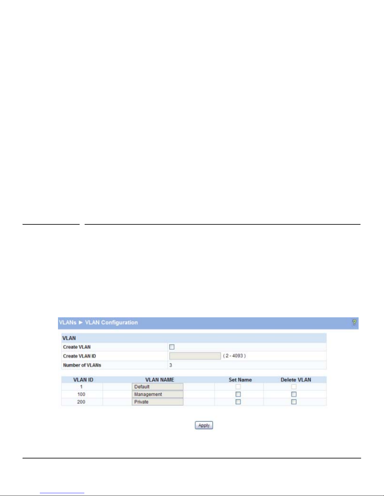
To display the VLAN Configuration page, click VLANs > VLAN Configuration in the navigation pane. As
shown in the example configuration in Figure 7-1, three VLANs are available.
Figure 7-1. VLAN Configuration Page
7-1
Page 54
Virtual LAN
VLAN Ports
Table 7-1. VLAN Configuration Fields
Field Description
Create VLAN Select this box to create a new VLAN.
Create VLAN ID Specify the numeric VLAN Identifier from 2 to 4093 and click Apply to create the VLAN.
Note: VLAN ID 1 is pre-configured on the switch and is always named “Default.” The default
VLAN cannot be deleted.
Number of VLANs The current number of VLANs. Up to 64 VLANs can be created.
VLAN Name
Delete VLAN
Set Name
■ Click Apply to save any changes to the for the currently selected trunk. The changes take effect
After the VLAN ID has been created using the previously described fields, you can apply a name
to it or delete it.
• To delete a VLAN, select the Delete VLAN box and click Apply. The default VLAN cannot be
deleted.
• To specify a VLAN name, select the Set Name box, type a name in the VLAN Name field, and
click Apply. A VLAN name can have up to 32 alphanumeric characters, including blanks.
immediately. Use the Maintenance > Save Configuration page to have the settings remain in effect
after a reboot.
VLAN Ports
Use the VLAN Ports page to view the Port VLAN ID that a port will assign to untagged frames that it
forwards, and to configure the port priority.
To access the VLAN Ports page, click VLANs > VLAN Ports in the navigation pane.
Figure 7-2. VLAN Ports Page
7-2
Page 55

Participation / Tagging
Virtual LAN
Table 7-2. VLAN Ports Fields
Field Description
Interface Select the port on which to configure the VLAN settings.
PVID The VLAN ID that this port will assign to untagged frames or priority-tagged frames received
on this port (range 1–4093, default = 1). The PVID is not user-configurable and always
corresponds to VLAN ID of the port’s untagged VLAN membership. You assign ports to VLANs
on the VLAN Participation / Tagging page.
The PVID value displays as None if all the VLANs are configured as tagged on this port or if this
port is configured as the destination port in a port mirroring configuration.
Port Priority Specify the default 802.1p priority assigned to untagged packets arriving at the port. A value of
0 indicates the lowest priority, commonly used for routine traffic, and 7 indicates the highest
priority, often reserved for application such as voice and video. (0–7, default = 0)
Note Ingress Filtering is enabled on all ports; therefore, a frame is discarded if the port is not a member of
the VLAN that the frame is associated with. In a tagged frame, the VLAN is identified by the VLAN ID
in the tag. In an untagged frame, the VLAN is the Port VLAN ID specified for the port that received this
frame.
■ Click Apply to save any changes for the current boot session; the changes take effect
immediately. Use the Maintenance > Save Configuratio n page to have the settings remain in effect
after a reboot.
Participation / Tagging
Use this page to include ports or trunks in particular VLANs and to specify the tagging policy for
outgoing packets on a port or trunk.
Note ■ All ports are members of VLAN1 by default.
■ Each port must be a member of at least one VLAN. An error message is displayed if a user
attempts to exclude a port from participation in its only VLAN.
■ Ports belonging to a trunk cannot be assigned membership in a VLAN, although the trunk itself
can be a member of one or more VLANs. When a member port is added to a Trunk, it loses any
previous VLAN memberships and acquires those of the trunk. When deleted from a trunk, a
port loses the VLAN memberships of the trunk and acquires untagged membership in VLAN 1.
To access the Participation / Tagging page, click VLANs > Participation / Tagging in the navigation pane.
As shown in the example configuration in Figure 7-3, VLAN 1 is selected for configuration. Ports 1, 2,
and 5 are configured as untagged members of VLAN1, and Trunk1 and Trunk2 are also members. Ports
3, and 4, and 7, and 8 are greyed-out because they are included in Trunk1 and Trunk2 respectively, and
receive their VLAN assignments from the trunk. Port 6 is greyed-out because it is configured as a
destination port in a port mirroring configuration, and cannot be assigned to a VLAN.
7-3
Page 56
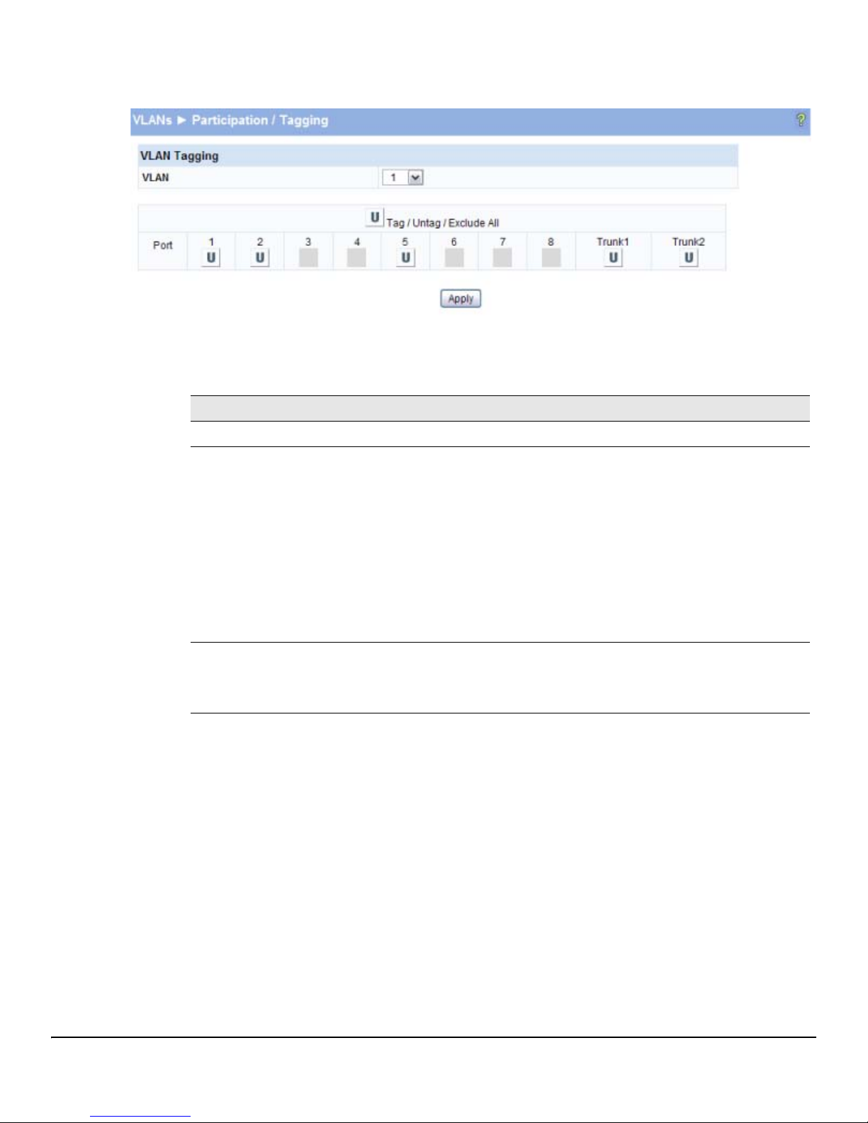
Virtual LAN
Participation / Tagging
Figure 7-3. Participation/Tagging Page
Table 7-3. Participation/Tagging Fields
Field Description
VLAN Select the VLAN to configure.
Tag / Untag / Exclude All For a port or trunk to participate in a VLAN, its tagging policy must be defined. By default,
all ports and trunks are configured as untagged members of VLAN1, and are excluded
from all other newly created VLANs.
You can use the Tag / Untag / Exclude All box to configure all ports at once. Click this
box until the appropriate options displays:
• E—exclude all ports from this VLAN.
• T—participate in the selected VLAN and tag all frames.
• U—participate in the selected VLAN and leave all outgoing frames untagged. Each
port can have only one untagged VLAN membership. If a port is an untagged member
of a VLAN and a second VLAN is selected for untagged membership, then the first
VLAN membership is automatically changed to E (Exclude).
Then, you can use the Port boxes to refine the ports participation and tagging settings.
Port Use the individual port boxes to specify whether a port will participate in this VLAN by
identifying the tagging policy as described above, or by excluding the port from the
VLAN.
Refer to the online help for further information about Participation / Tagging settings.
■ Click Apply to save any changes for the current boot session; the changes take effect
immediately. Use the Maintenance > Save Configuration page to have the settings to remain in
effect after a reboot.
7-4
Page 57

Example—Creating a Management VLAN
Example—Creating a Management VLAN
A management VLAN can be created to restrict user access. Access restrictions can be applied to a set
of users capable of accessing the HP ProCurve 1810G switch software. Follow these steps to create a
management VLAN.
Note ■ Prior to configuring a management VLAN/port, ensure that the port being configured is
connected to a network that is accessible through that port and management VLAN; otherwise,
you will lose connectivity instantly upon configuration.
■ If more than one port are configured as untagged VLAN members of management VLAN
(through the VLAN Participation / Tagging page), users can have management access through
all these ports irrespective of the configured management port
1. Use the VLAN Configuration page to create a VLAN ID for use as the management VLAN.
2. Display the Network Setup > Get Connected page and do the following:
•In the Management VLAN ID field, specify the VLAN ID created in Step 1.
•In the Management Port field, select the port you want to use as the management port.
Virtual LAN
Wait a few moments for the switch to configure the new management VLAN/port before attempting to
log in.
7-5
Page 58

Virtual LAN
Example—Creating a Management VLAN
7-6
Page 59
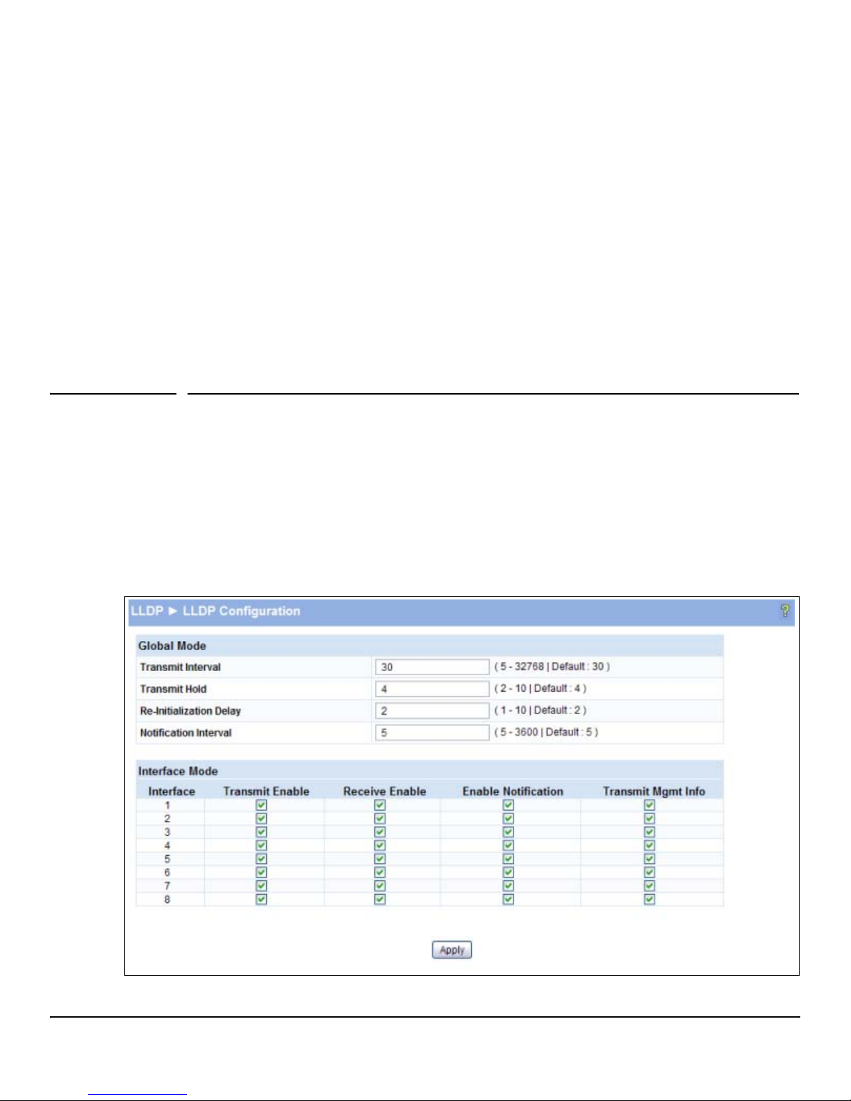
Link Layer Discovery Protocol (LLPD)
The IEEE 802.1AB defined standard, Link Layer Discovery Protocol (LLDP), allows stations residing on an IEEE
802 LAN to advertise major capabilities and physical descriptions. This information is viewed by a network
manager to identify system topology and detect bad configurations on the LAN.
LLDP is a one-way protocol; there are no request/response sequences. Information is advertised by stations
implementing the transmit function, and is received and processed by stations implementing the receive function.
The transmit and receive functions can be enabled/disabled separately per port. By default, both transmit and
receive are enabled on all ports. The application is responsible for starting each transmit and receive state
machine appropriately, based on the configured status and operational state of the port.
LLDP Configuration
Use the LLDP Configuration page to specify global LLDP parameters and to configure the protocol on
individual ports.
8
To display the LLDP Configuration page, click LLDP > LLDP Configuration in the navigation pane. Note
that LLDP is enabled by default on all ports.
Figure 8-1. LLDP Configuration Page
8-1
Page 60

Link Layer Discovery Protocol (LLPD)
LLDP Configuration
Table 8-1. LLDP Configuration Fields
Field Description
Transmit Interval Specify the interval at which frames are transmitted. The default is 30 seconds, and the
Transmit Hold Specify the multiplier on the transmit interval to assign to TTL (range 2–10, default = 4).
Re-Initialization Delay Specify the delay before a re-initialization (range 1–10 seconds, default = 2).
Notification Interval Specify a limit for the transmission of notifications (range 5–3600 seconds, default = 5).
Interface The port to be affected by these parameters.
Transmit Enable Enable or disable the transmission of LLDP PDUs. The default is enabled.
Receive Enable Enable or disable the ability of the port to receive LLDP PDUs. The default is enabled.
Enable Notification Enable to have LLDP generate a log file entry.
Transmit Mgmt Info Enable or disable the transmission of management information with the LLDP PDUs. The
Global
valid range is 5–32768 seconds.
Interface
default is enabled.
■ Click Apply to save any changes for the current boot session; the changes take effect
immediately. Use the Maintenance > Save Configuration page to have the settings remain in effect
after a reboot.
To view LLDP statistics, click Status > LLDP Statistics in the navigation pane.
8-2
Page 61
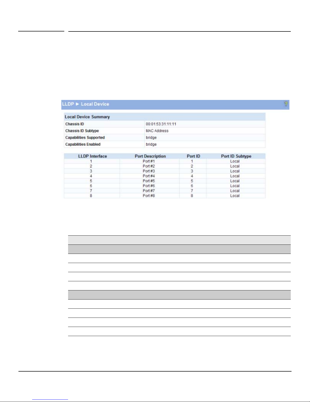
Link Layer Discovery Protocol (LLPD)
LLDP Local Device
LLDP Local Device
Use the LLDP Local Device page to view information about devices on the network for which the switch
has received LLDP information.
To display this page, click LLDP > Local Device in the navigation pane.
Figure 8-2. LLDP Local Device Information Page
Table 8-2. LLDP Local Device Information Fields
Field Description
Local Device Summary
Chassis ID The source of the chassis identifier.
Chassis ID Subtype The type of the source of the chassis identifier.
Capabilities Supported Displays the system capabilities of the local system.
Capabilities Enabled Displays the system capabilities of the local system that are supported and enabled.
LLDP Interface Description
LLDP Interface The interface on which LLDP 802.1AB frames can be transmitted.
Port Description The description of the selected port associated with the local system.
Port ID The source of the port identifier.
Port ID Subtype Displays the type of the source of the port ID.
■ Click the Refresh link above the page to update the page with the latest data from the switch.
8-3
Page 62
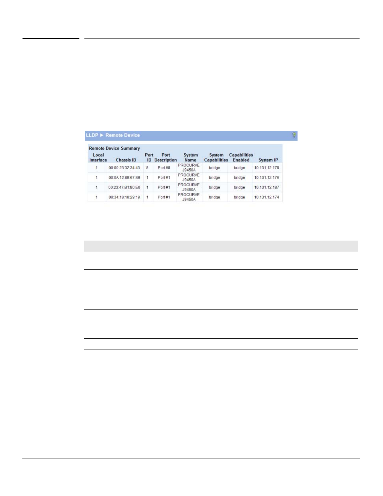
Link Layer Discovery Protocol (LLPD)
LLDP Remote Device
LLDP Remote Device
Use the LLDP Remote Device page to view information about remote devices for which the switch has
received LLDP information. To display the LLDP Remote Device page, click LLDP > Remote Device in
the navigation pane.
As shown in the example configuration in Figure 8-3, the remote device is connected to interface 3.
Figure 8-3. LLDP Remote Device Page
Table 8-3. LLDP Remote Device Fields
Field Description
Local Interface The port on the local system that received the LLDP data from the remote
Chassis ID The chassis component associated with the remote system.
Port ID The physical address of the port on the remote device that sent the LLDP data.
Port Description The port description configured on the remote device. If the port description is not
System Name The system description configured on the remote device. If the system
System Capabilities The capabilities of on the remote device.
Capabilities Enabled The capabilities on the remote device that are enabled.
System IP The IP address of the remote device.
■ Click the Refresh link above the page to re-display the page with current settings from the
system.
configured, the field is blank.
description is not configured, the field is blank.
switch.
8-4
Page 63
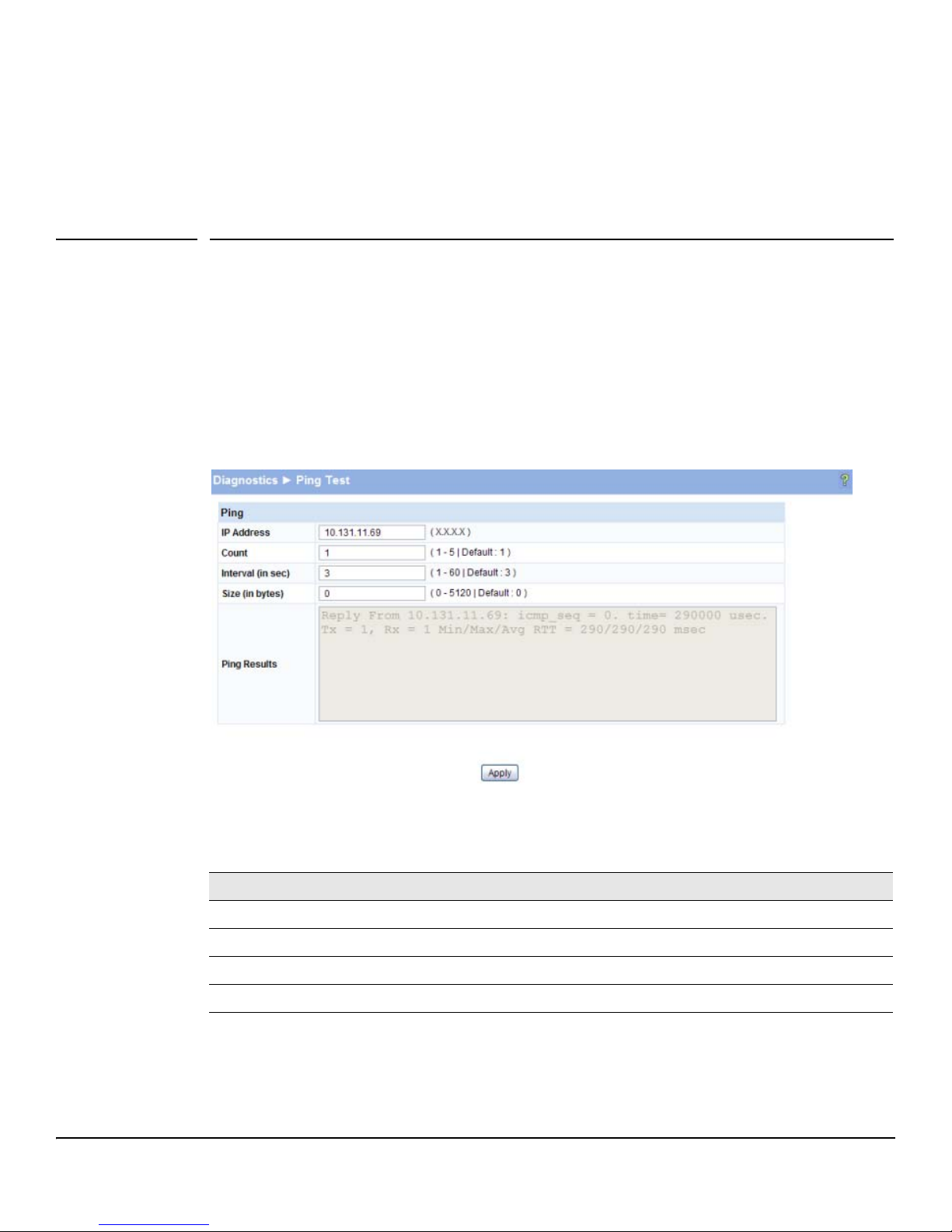
Diagnostics
9
Ping Test
Use the Ping Test page to determine whether another device on the network is reachable. Ping provides
a synchronous response when initiated.
To display the Ping Test page, click Diagnostics > Ping Test in the navigation pane. The following example
shows the output of the ping test.
Figure 9-1. Ping Test Page
Table 9-1. Ping Test Fields
Field Description
IP Address Specify the IP address of the host you want to reach.
Count Specify the number of packets to send. (Range 1 - 5 packets, Default = 1)
Interval Specify the delay between ping packets. (Range 1–60 seconds, Default = 3 seconds)
Size Specify the size of the ping packet to be sent. (Range 0–5120, Default = 0)
9-1
Page 64
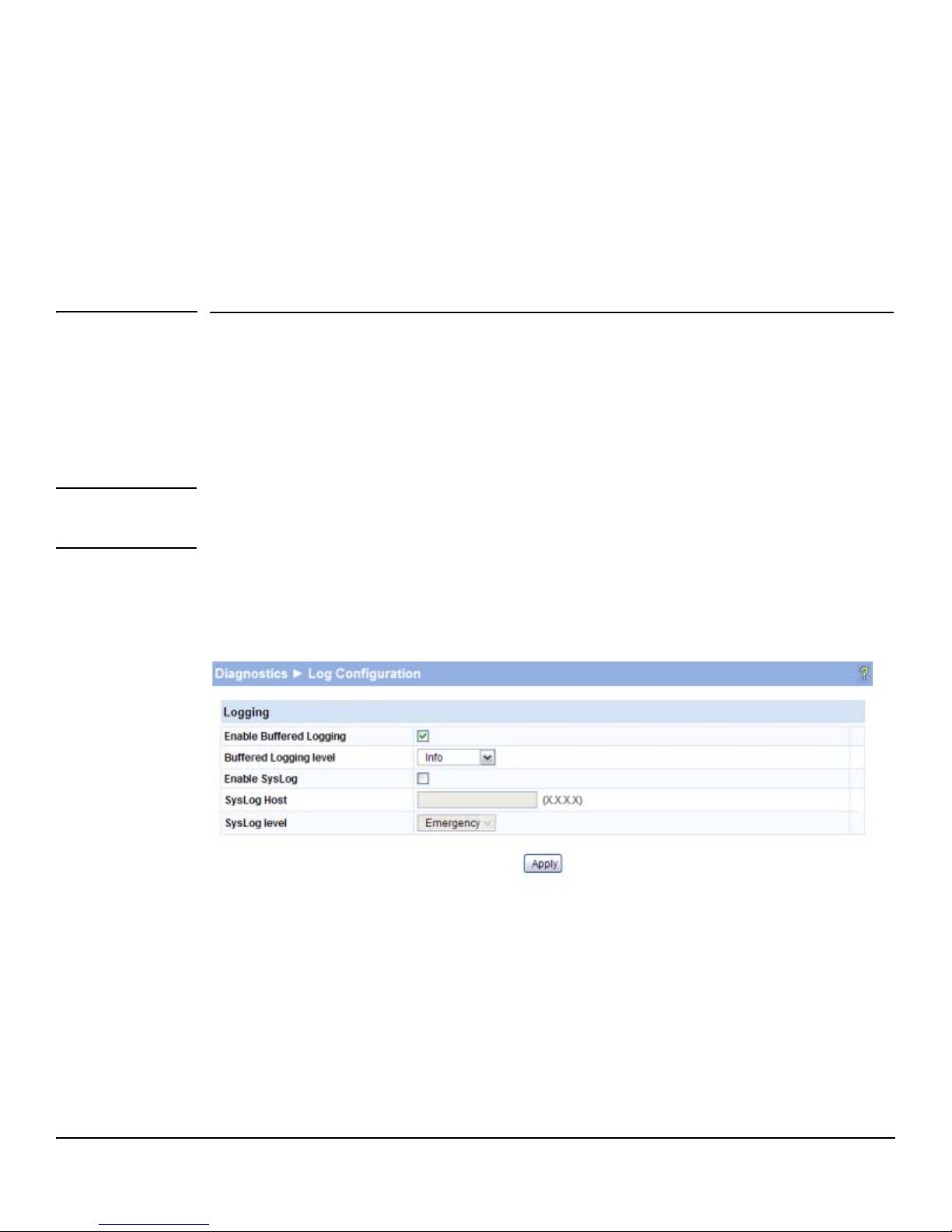
Diagnostics
Log Configuration
■ Click Apply to ping the specified host. The output includes the following data:
• IP Address— The IP address of the device that was pinged.
• Sequence— The Internet Control Message Protocol (ICMP) number of the packet, starting
from 0.
• Time—The ping reply status.
• Transmitted Packets— The number of packets sent.
• Received Packets — Number of packets received.
• Min/Max/Avg RTT—Specifies the Minimum, Maximum, Average Round Trip Time (msec).
Log Configuration
HP ProCurve 1810G switch software supports logging system messages to the Log file or forwarding
messages over the network using the Syslog protocol. Syslog messages can be captured by a designated
host on the network that is running a Syslog daemon.
Note The log file is limited to 100 entries. The most recent 100 defects are displayed; index numbering may
not be 1-100. See your syslog entries to view more than 100 events.
To display the Log Configuration page, click Diagnostics > Log Configuration in the navigation pane.
Figure 9-2. Log Configuration Pages
9-2
Page 65
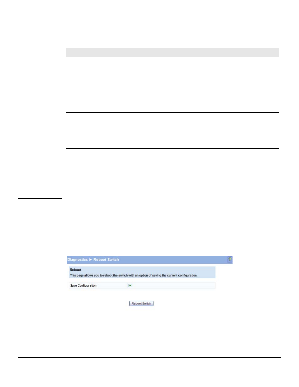
Table 9-2. Log Configuration Fields
Field Description
Diagnostics
Reboot Switch
Enable Buffered
Logging
Buffered Logging
Level
Enable Syslog Select to enable the switch to send Syslog messages.
Syslog Host Specify the IP address of a host on the network running a Syslog daemon that will capture the
Syslog Level Specify a Syslog logging level (Emergency–Debug as described above). A log records
■ Click Apply to save any changes for the current boot session; the changes take effect
Specify which type of system messages are logged by using the Buffered Logging Level setting:
• Emergency: Alerts the user of the highest level of system error classified as urgent.
• Alert: Alerts the user of a high level of system error.
• Critical: Alerts the user of a high level of system error which must be immediately addressed.
• Error: Alerts the user of an error in the system.
• Warning: Warns the user of an impending system error of a specified operation.
• Notice: Notifies the user of a system error.
• Info: Provides the user with system information.
• Debug: An internal note to reconcile programming code.
Specify a logging level (Emergency–Debug as previously described). A log records messages
equal to or above a configured console logging level.
messages.
messages equal to or above a configured console logging level.
immediately. Use the Maintenance > Save Configuratio n page to have the settings remain in effect
after a reboot.
Reboot Switch
Use this feature to perform a software reboot of the switch. Be sure to save any applied changes prior
to rebooting. To access this page, click Diagnostics > Reboot Switch.
Figure 9-3. Reboot Switch Page
9-3
Page 66
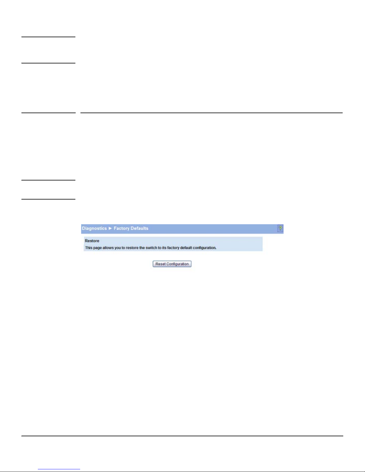
Diagnostics
Factory Defaults
Note If you have downloaded a configuration file and want those setting to take affect after the next reboot,
be sure to clear the Save Configuration check box. Otherwise, the configuration file will be overwritten
and the switch will reboot with the current configuration instead of the downloaded configuration.
■ Select Save Configuration if you want the current configuration to be saved prior to the reboot.
■ Click Reboot Switch to reboot the switch. The current HTTP session is terminated.
Factory Defaults
Two configuration images are kept in system memory: one image contains custom settings; the other
image contains the factory defaults. Use this page to restore all settings to the factory defaults page.
To access this page, click Diagnostics > Factory Defaults.
CAUTION Backup the current configuration file prior to restoring the factory defaults configuration.
See “Backup Manager” on page 10-1 for instructions.
Figure 9-4. Factory Defaults Page
■ Click Reset Configuration to restore the system to the default settings. You can use the
Maintenance > Save Configuration page to ensure that the factory defaults remain in effect after
a reboot. Or, use the Maintenance > Reboot Switch page and ensure that the Save Configuration
check box is selected prior to rebooting.
9-4
Page 67

Diagnostics
Support File
Support File
Use the support file page to display summary information for the switch on a single page. The support
file page includes the following data:
■ System description
■ The active Image and the image that will be active after a reboot, and the user-configured
descriptions of these images.
■ Buffered log messages
■ Logging configuration details
■ IP configuration details
■ Port configuration details
■ Jumbo frames configuration details
■ Green mode administrative status
■ MAC address forwarding table and summary statistics
■ VLAN configuration and membership details
■ Trunk configuration details
■ LLDP configuration, global statistics, and local and remote device summaries
■ Port mirroring configuration
■ Loop protection status per interface
To access this page, click Diagnostics > Support File in the navigation pane.
This data also displays on status pages for each particular feature. For descriptions of these items,
refer to the related sections in this document.
To save the Support File data to a file, click Save As located at the bottom of the page.
You can print the text from your text editor. Alternatively, your browser may support printing only the
frame that contains the data (that is, it excludes the navigation pane and Web Applet) directly from the
Web page. Right-click the data area to see if your browser provides this option.
9-5
Page 68
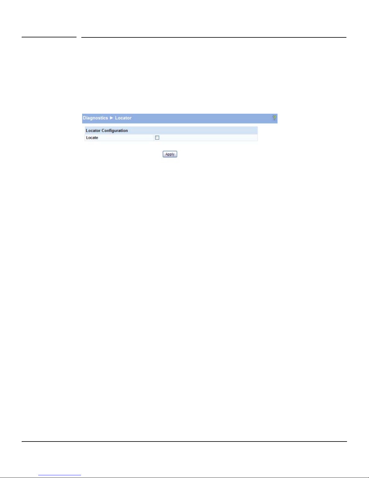
Diagnostics
Locator
Locator
The Locator LED is a special LED that enables locating the device physically. When enabling the Locate
setting via the Web interface, the Locate LED on the switch blinks for 30 minutes and then turns off.
To access this page, click Diagnostics > Locator in the navigation pane.
Figure 9-5. Locator Page
■ Select Locate and click Apply to cause the Locator LED on the switch to blink for 30 minutes.
9-6
Page 69
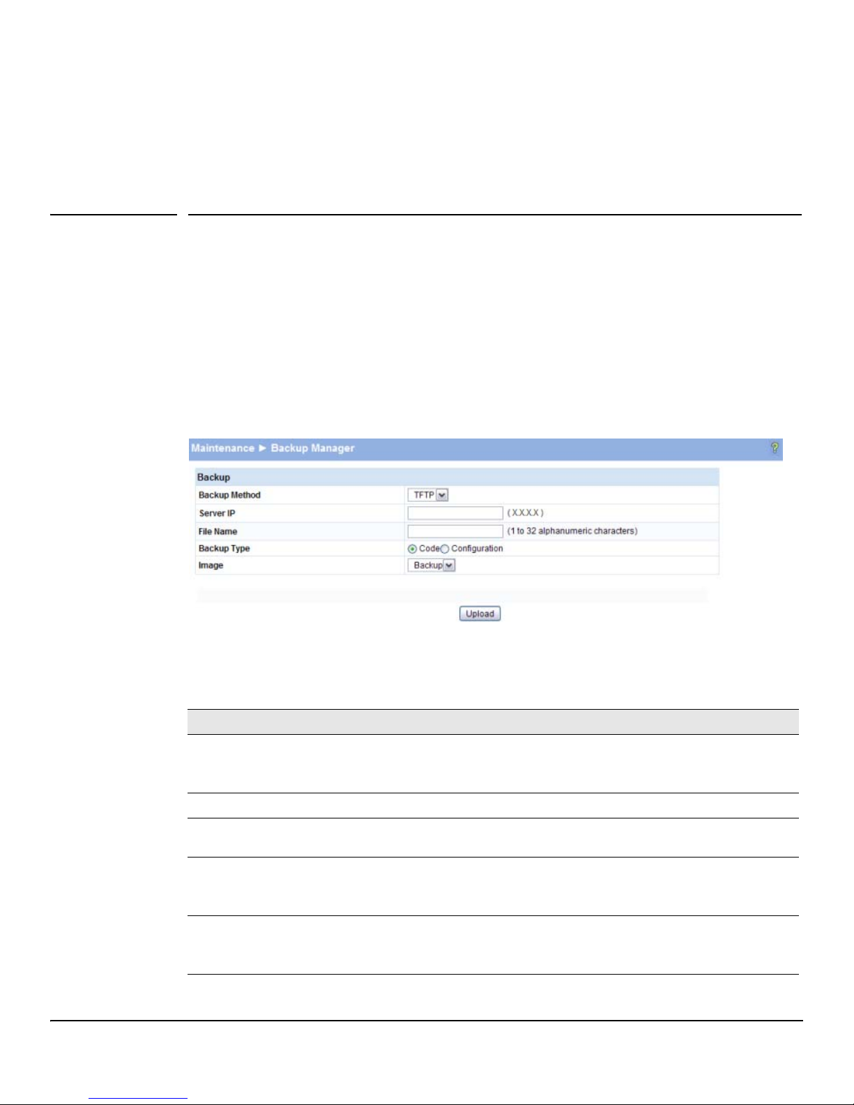
Maintenance Pages
Backup Manager
Backup Manager page provides a means to save a backup copy of the switch’s image or configuration
files on a local system or network directory. To access this page, click the Maintenance > Backup
Manager.
The page displays different options depending on the protocol and image or file type selected for the
backup. As shown in the example in Figure 10-1, TFTP (Trivial File Transfer Protocol) has been selected
as the backup method for saving the code (entire image) onto a server.
Figure 10-1. Backup Manager Page
10
Table 10-1. Backup Manager Fields
Field Description
Backup Method Select the protocol to use:
Server IP (TFTP backup only) If a TFTP backup is to be performed, enter the IP address of the TFTP server.
File Name (TFTP backup only) If a TFTP backup is to be performed, enter the file name with which backup must be
Backup Type Select the image or file to be backed up:
Image Name If Code is selected as the Backup Type, select one of the two images stored in memory:
• HTTP—The file is downloaded over the current browser session.
• TFTP—This requires a TFTP server operating on the system/network.
saved. This can differ from the actual file name on the switch.
• Code—The entire image is backed up (default name switchdrvr.stk).
• Configuration—Only the configuration file is backed up (default name config.bin).
• Active—The currently active image is backed up.
• Backup—The backup image is backed up. name config.bin).
10-1
Page 70
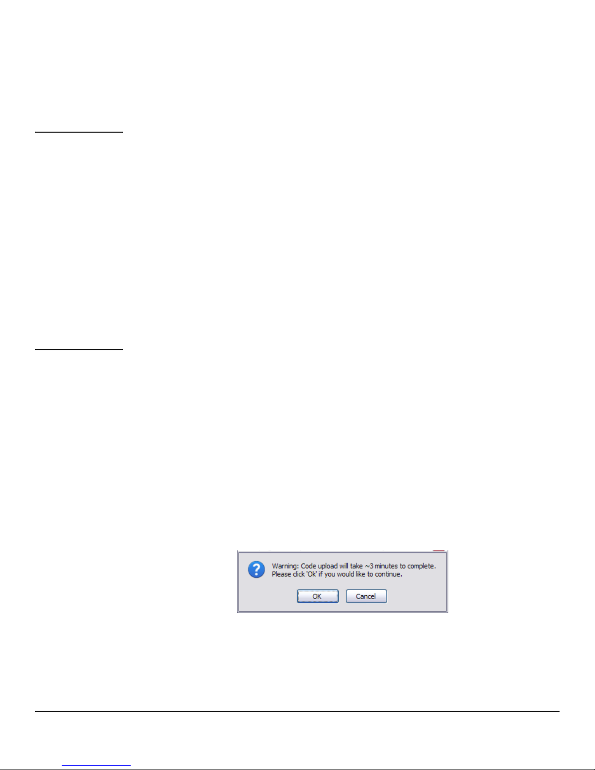
Maintenance Pages
Backup Manager
■ For a backup using HTTP, click Apply to begin the backup process. A window displays with a
prompt to save the file in the desired location.
■ For backup using TFTP, ensure that the TFTP server is running and click Apply. Use a TFTP
application to initiate the backup.
Note If using Internet Explorer, when you attempt a backup operation from a secure HTTP session using
the HTTP protocol, you may receive the following error message, even though the document is available
and downloaded from the server:
Internet Explorer cannot download filename from <site name>. Internet Explorer was not able to open this
Internet site. The requested site is either unavailable or cannot be found. Please try again later.
This error happens due to security limitations with Internet Explorer. Recent versions do not have this
problem. To perform the operation, configure the following settings in your browser:
1. Click Tools > Internet Options and display the Advanced tab.
2. In the Security settings, select Do not save encrypted pages to disk.
3. Try the backup operation again.
4. After the backup operation is complete, restore your settings to the original values to avoid Web
performance issues.
If you use a browser other than Microsoft Internet Explorer, such as Firefox or Mozilla, the download
of the attachment should work as expected.
Example—Backing Up a Configuration File
Follow these instructions to back up a configuration file.
1. In the Backup Method field, select the protocol to use to upload the file to the system. To save the
file on a local or network drive, select HTTP. To save the file on a TFTP server, select TFTP.
2. If TFTP is selected, specify the IP address of the TFTP server and the name to assign to the file
when it is saved.
3. Select Configuration in the Backup Type field.
4. Click Apply.
A window like following displays (the text may differ depending on the selected protocol and
backup type):
10-2
Page 71
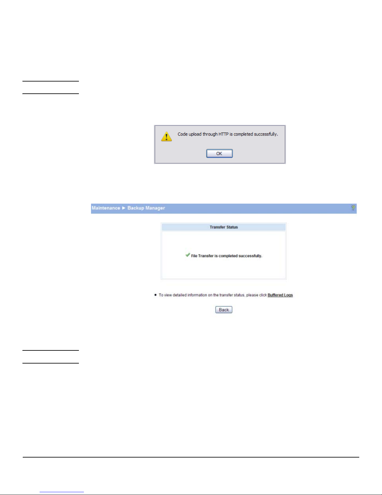
5. Click OK. For an HTTP transfer, browse to the location where you want to save the file.
A progress bar indicates that the backup is in progress and the page displays the following message:
Code (Configuration) upload through HTTP (TFTP) is in Progress.
Please wait...
CAUTION Do not disturb the browser window while the transfer is in progress.
When the backup is complete, a window like the following displays.
6. Click OK.
The Backup Manager page displays the following status message:
Maintenance Pages
Backup Manager
7. Click Back to re-display the Backup Manager page.
Note To restore a backed-up code or configuration file, use Update Manager.
10-3
Page 72
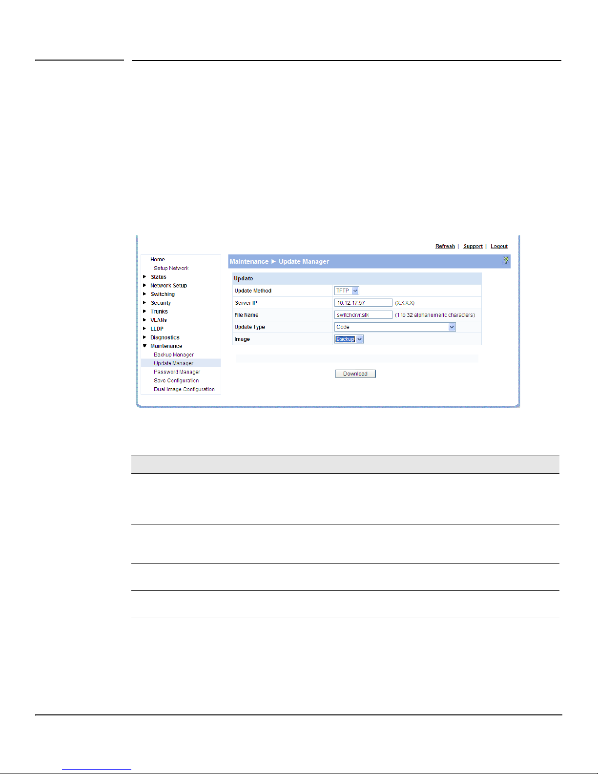
Maintenance Pages
Update Manager
Update Manager
Update Manager enables a new image or configuration file to be uploaded from the local system or
network to the switch. To access this page, click Maintenance > Update Manager in the navigation pane.
Update Manager displays different options depending on the transfer protocol, file or image type
selected for an update. In the example in Figure 10-2, the inactive (or “Backup”) image on the switch
is being updated with the file named switchdrvr.stk from a TFTP server. For example, if the image1
file is being used as the currently-active image running on the switch, then the image2 file is the backup
file to be updated.
Figure 10-2. Update Manager Page
Table 10-2. Update Manager Fields
Field Description
Update Method Select the protocol to use:
• HTTP—The file is downloaded using HTTP from a local or remote drive.
• TFTP—The file is downloaded using TFTP from a TFTP server operating on the system/
network.
Browse for file
(HTTP upload only)
Server IP
(TFTP upload only)
File Name
(TFTP upload only)
If HTTP is used for the software update, click Browse to select the designated file.
Note: If the file name differs from the default name on the switch, the file will be renamed to the
default name when uploaded (see the Update Type field description).
If a TFTP download is performed, enter the IP address of the TFTP server.
If a TFTP download is performed, enter the name of the software update file on the TFTP server.
10-4
Page 73

Field Description
Update Type Select the file type to be updated:
• Code—Update the software image file specified.
• Configuration—Update up the configuration file.
• To update an SSL certificate or key encryption file, select the certificate type (for a description
of these files, see “Secure Connection” on page 5-2):
• SSL Trusted Root Certificate PEM File—SSL Trusted Root Certificate File which is encoded
using the Privacy Enhanced Mail (PEM) protocol.
• SSL Server Certificate PEM File—SSL Server Certificate File (PEM-encoded).
• SSL DH Weak Encryption Parameter PEM File—SSL Diffie-Hellman Weak Encryption
Parameter File (PEM encoded).
• SSL DH Strong Encryption Parameter PEM File— SSL Diffie-Hellman Strong Encryption
Parameter File (PEM encoded).
Maintenance Pages
Update Manager
Image
(for Code updates
only)
If Code is selected as the update type, select which of the two images stored on the switch is to
be updated:
• Active—The uploaded image will replace the currently active image.
• Backup—The uploaded image will replace the backup image.
Example—Updating the Switch Software
CAUTION It is recommended that you back up the image file before updating it. See “Backup Manager”
on page 10-1 for instructions.
Follow these instructions to update the switch software (that is, a firmware code image):
1. In the Update Method field, select the protocol to use to upload the file to the system. If the file is
located on a local or network drive, select HTTP. If the file is located on a TFTP server, select TFTP.
2. If TFTP is selected, specify the IP address of the TFTP server and the name of the file as it appears
on the server.
If HTTP is selected, browse to locate the file on your network or local drive.
3. In the Update Type field, select Code.
4. In the Image field, choose Backup or Active.
If you choose Backup, the inactive (backup) image file will be updated. In the example in Figure 10-
2 on page 10-4, the Backup image file is selected for update.
If you choose Active, the active image file will be updated.
5. Click Download.
A warning page like the following displays (the text may differ depending on the protocol selected):
10-5
Page 74
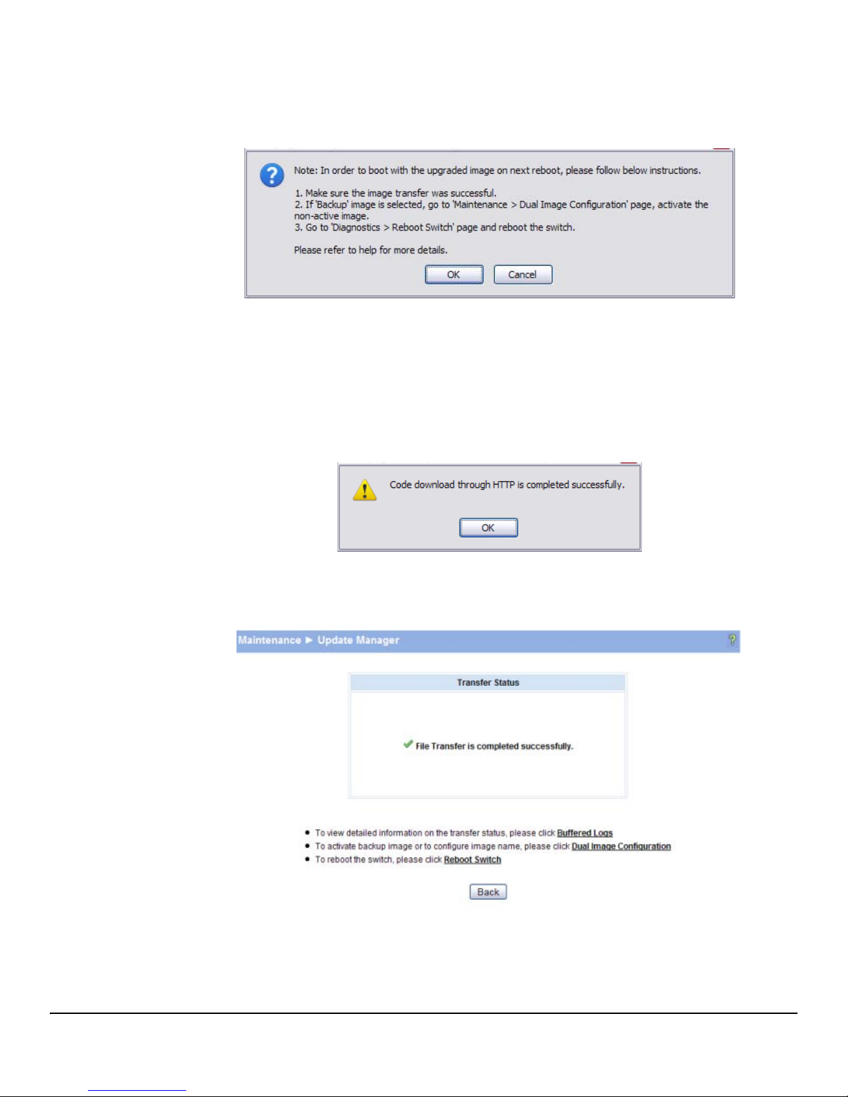
Maintenance Pages
Update Manager
6. Click OK.
The following page displays:
7. Click OK.
The following message displays on the Update Manager page:
Code (Configuration) download through HTTP (TFTP) is in Progress.
Please wait...
When the transfer is complete, a window like the following displays:
8. Click OK.
Update Manager displays the following status message:
10-6
Page 75
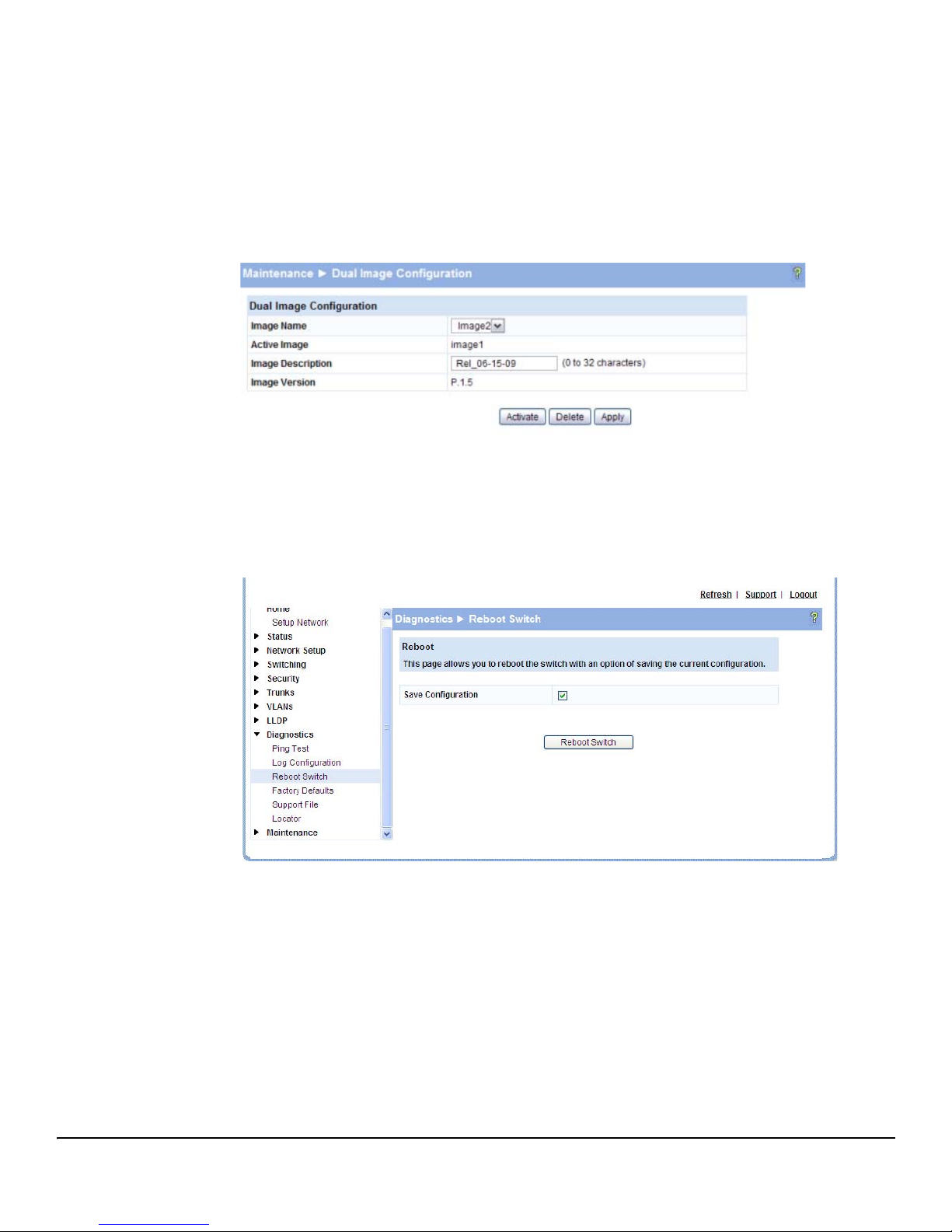
Maintenance Pages
Update Manager
9. Click Back to re-display the Update Manager page.
Note that, in this example, the image was downloaded as the inactive (backup) image. To complete
the update process and to activate the backup image as the operating software, use the Dual Image
Configuration page.
In the following example, Image1 is the active image, and Image2 is the newly updated backup
image. By clicking Activate, Image2 will be activated on the next reboot (and Image1 will become
the inactive backup image).
10. (Optional) Add a description for the selected image (Image2) and click Apply.
11. Click Activate to activate the selected image on the next reboot.
Note: You can verify the next active image by viewing the Status > Dual Image screen.
12. Click Diagnostics > Reboot Switch, and then click Reboot Switch to complete the update.
Wait about a minute, then refresh your browser to re-display the Web interface.
Upon reboot, the previously-active image (Image1, in this example) will become the inactive
(backup) image.
10-7
Page 76
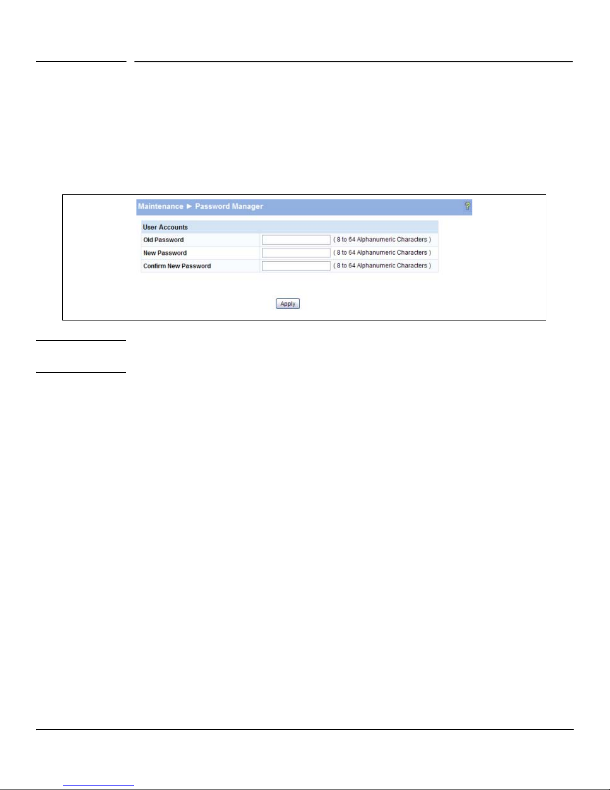
Maintenance Pages
Password Manager
Password Manager
Use the Password Manager to change the password used to access the Web interface. To access this
page, click the Maintenance > Password Manager.
Figure 10-3 shows the Password Manager page.
Figure 10-3. Password Manager Page
Note Passwords must be at least 8 characters but no more than 64 characters long. Passwords are case
sensitive.
■ Enter the old password and the new password twice, and click Apply. At the next log on, use
the new password. Use the Maintenance > Save Configuration page to ensure that the new
password remains in effect after a reboot.
10-8
Page 77
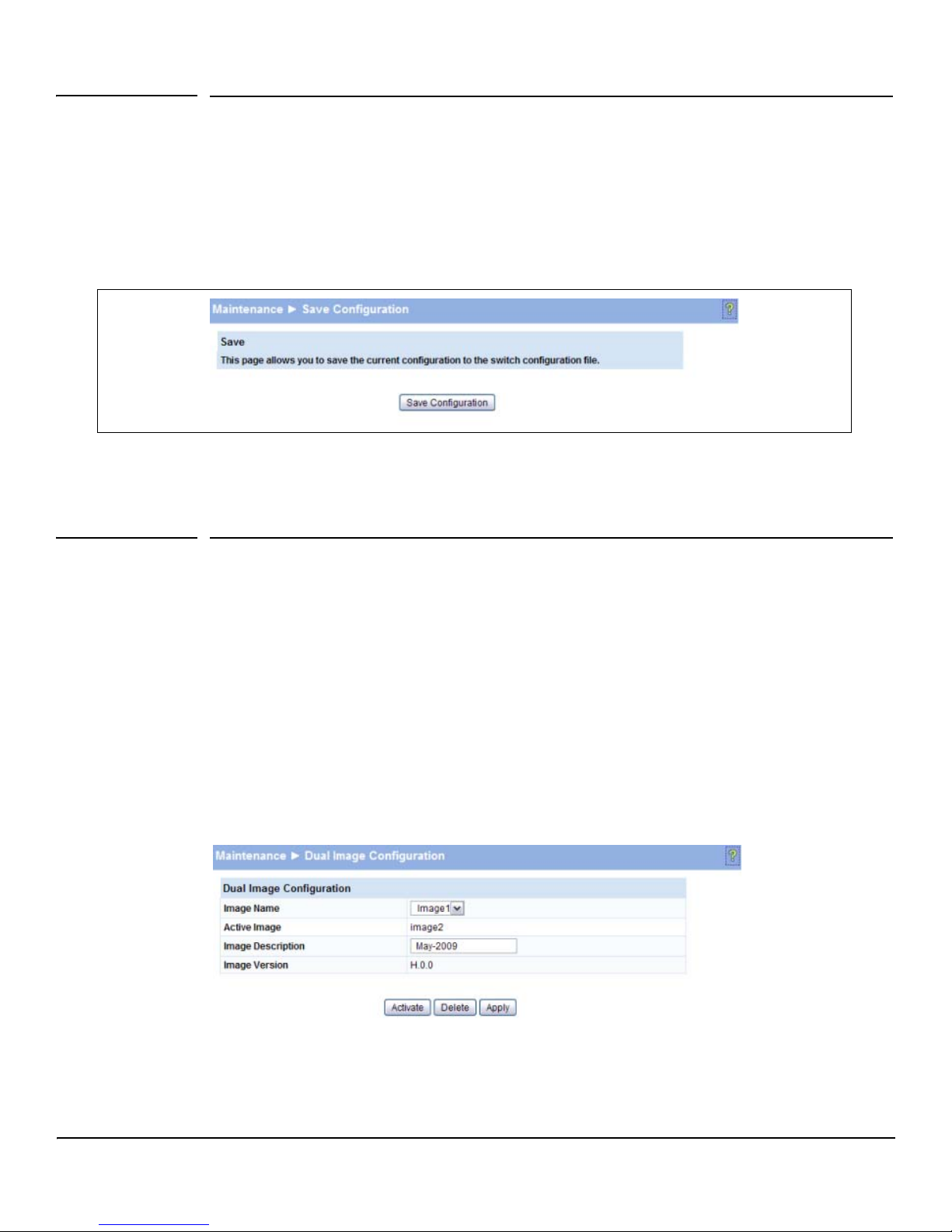
Maintenance Pages
Save Configuration
Save Configuration
Use the Save Configuration page to save any changes applied since the last reboot. If the switch reboots
before the applied changes are saved, the changes will be lost. To access this page, click
Maintenance > Save Configuration.
Figure 10-4. Save Configuration Page
■ Click Save Configuration to save the changes made during this session.
Dual Image Configuration
Use the Dual Image Configuration page to name and change the next bootup image. To access this
page, click Maintenance > Dual Image Configuration.
The Dual Image Configuration allows activating either of the stored images: Image1 or Image2. When
one image is activated, the other image serves as a backup; if Image1 either fails or does not boot, then
the other image can be activated.
As shown in Figure 10-5, the current active image is Image2. Image1 can be set to be activated, deleted,
or an image description can be applied.
Figure 10-5. Dual Image Configuration Page
10-9
Page 78

Maintenance Pages
Dual Image Configuration
Table 10-3. Dual Image Configuration Fields
Field Description
Image Name Select the image you want to perform an action on. You can activate the selected image, delete
it, or configure a description of it. Options are Image1 and Image2.
Active Image The currently active image.
Image Description Specify a description of the image selected in the Image Name field.
Image Version The software version associated with the active image.
■ Click Activate to activate the selected image selected in the Image Name field. Be sure to
configure the Image Description field to the version of the image loaded so that users can easily
distinguish between the images.
■ Click Apply to apply a description to the image selected in the Image Name field.
■ Click Delete to delete the image selected in the Image Name field.
To view dual image status information, click Status > Dual Image Status in the navigation pane.
10-10
Page 79

Page 80

Technology for better business outcomes
To learn more, visit www.hp.com/go/procurve/
© Copyright 2009 Hewlett-Packard Development Company, L.P. The information
contained herein is subject to change without notice. The only warranties for HP products
and services are set forth in the express warranty statements accompanying such products
and services. Nothing herein should be construed as constituting an additional warranty.
HP will not be liable for technical or editorial errors or omissions contained herein.
August 2009
Manual Part Number
5992-5475
 Loading...