

Page 1
HP Networking
Installation Guide
Forworld-widesupportonall
HP Network Connectivity Products
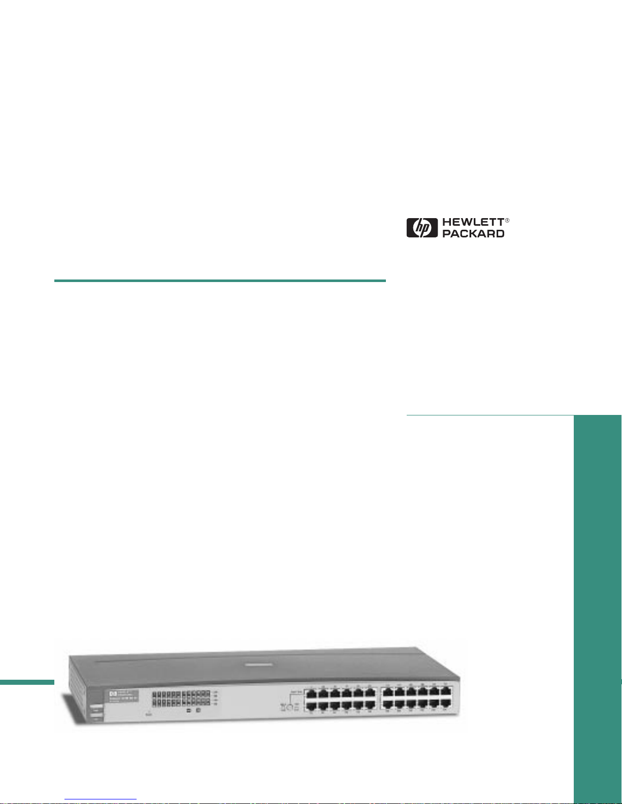
10/100 Hub 12
10/100 Hub 24
HP ProCurve 10/100 Hubs
Page 2

Roadhw0.bk : ROADHW0.FM Page i Thursday, May 28, 1998 5:40 PM
HP ProCurve 10/100 Hubs
Installation Guide
http://www.hp.com/go/network_city
Page 3

Roadhw0.bk : ROADHW0.FM Page ii Thursday, May 28, 1998 5:40 PM
© Copyright 1998 Hewlett-Packard Company
All Rights Reserved.
This document contains information which is protected by
copyright. Reproduction, adaptation, or translation without
prior permission is prohibited, except as allowed under the
copyright laws.
Publication Number
5967-2280
July 1998
Applicable Products
HP J3294A 10/100 Hub 12
HP J3295A 10/100 Hub 24
Disclaimer
The information contained in this document is subject to
change without notice.
HEWLETT-PACKARD COMPANY MAKES NO WARRANTY
OF ANY KIND WITH REGARD TO THIS MATERIAL,
INCLUDING, BUT NOT LIMITED TO, THE IMPLIED
WARRANTIES OF MERCHANTABILITY AND FITNESS
FOR A PARTICULAR PURPOSE. Hewlett-Packard shall not
be liable for errors contained herein or for incidental or
consequential damages in connection with the furnishing,
performance, or use of this material.
Hewlett-Packard assumes no responsibility for the use or
reliability of its software on equipment that is not furnished
by Hewlett-Packard.
Warranty
See the Customer Support/Warranty booklet included with
the product.
A copy of the specific warranty terms applicable to your
Hewlett-Packard products and replacement parts can be
obtained from your HP Sales and Service Office or
authorized dealer.
Hewlett-Packard Company
8000 Foothills Boulevard, m/s 5552
Roseville, California 95747-5552
http://www.hp.com/go/network_city
Page 4

Roadhw0.bk : Roadhw0TOC.fm Page iii Thursday, May 28, 1998 5:40 PM
Contents
1 Introducing the HP ProCurve 10/100 Hubs
Front of the Hubs
Network Ports . . . . . . . . . . . . . . . . . . . . . . . . . . . . . . . . . . . . . . . . . . . . . . 1-3
Port LED Types . . . . . . . . . . . . . . . . . . . . . . . . . . . . . . . . . . . . . . . . . . . . . 1-3
LEDs for the 10/100Base-T Hubs . . . . . . . . . . . . . . . . . . . . . . . . . . . . . . . 1-4
LED Combinations . . . . . . . . . . . . . . . . . . . . . . . . . . . . . . . . . . . . . . . . . . 1-5
Reset Button . . . . . . . . . . . . . . . . . . . . . . . . . . . . . . . . . . . . . . . . . . . . . . . 1-5
Back of the Hubs
Power Connector . . . . . . . . . . . . . . . . . . . . . . . . . . . . . . . . . . . . . . . . . . . 1-5
Features
. . . . . . . . . . . . . . . . . . . . . . . . . . . . . . . . . . . . . . . . . . . . . . . . . . . . . . 1-6
. . . . . . . . . . . . . . . . . . . . . . . . . . . . . . . . . . . . . . . . . . . . . 1-2
. . . . . . . . . . . . . . . . . . . . . . . . . . . . . . . . . . . . . . . . . . . . . . 1-5
2 Installing the Hub
Included Parts
Installation Summary
Installation Precautions . . . . . . . . . . . . . . . . . . . . . . . . . . . . . . . . . . . . . . 2-3
1. Prepare the Installation Site . . . . . . . . . . . . . . . . . . . . . . . . . . . . . . . . 2-4
2. Verify the Hub Operates Correctly . . . . . . . . . . . . . . . . . . . . . . . . . . . 2-5
LED Behavior: . . . . . . . . . . . . . . . . . . . . . . . . . . . . . . . . . . . . . . . . . . 2-5
3. Mount the Hub . . . . . . . . . . . . . . . . . . . . . . . . . . . . . . . . . . . . . . . . . . . 2-6
Rack or Cabinet Mounting . . . . . . . . . . . . . . . . . . . . . . . . . . . . . . . . 2-6
Wall Mounting . . . . . . . . . . . . . . . . . . . . . . . . . . . . . . . . . . . . . . . . . . . 2-8
Horizontal Surface Mounting . . . . . . . . . . . . . . . . . . . . . . . . . . . . . . 2-8
4. Connect the Hub to a Power Source . . . . . . . . . . . . . . . . . . . . . . . . . 2-9
5. Some Basic Troubleshooting . . . . . . . . . . . . . . . . . . . . . . . . . . . . . . . . 2-9
. . . . . . . . . . . . . . . . . . . . . . . . . . . . . . . . . . . . . . . . . . . . . . . . 2-1
. . . . . . . . . . . . . . . . . . . . . . . . . . . . . . . . . . . . . . . . . . 2-2
Sample Network Topologies
Where to Go From Here
. . . . . . . . . . . . . . . . . . . . . . . . . . . . . . . . . . 2-10
. . . . . . . . . . . . . . . . . . . . . . . . . . . . . . . . . . . . . . 2-10
iii
Page 5

Roadhw0.bk : Roadhw0TOC.fm Page iv Thursday, May 28, 1998 5:40 PM
3 Troubleshooting
Basic Troubleshooting Tips
Diagnosing with the LEDs
Hardware Diagnostic Tests
Testing the Hub by Resetting It . . . . . . . . . . . . . . . . . . . . . . . . . . . . . . . . 3-4
Testing Twisted-Pair Cabling . . . . . . . . . . . . . . . . . . . . . . . . . . . . . . . . . . 3-4
HP Customer Support Services
. . . . . . . . . . . . . . . . . . . . . . . . . . . . . . . . . . . . 3-1
. . . . . . . . . . . . . . . . . . . . . . . . . . . . . . . . . . . . . 3-3
. . . . . . . . . . . . . . . . . . . . . . . . . . . . . . . . . . . . 3-4
A Specifications
B Cables and Connectors
Twisted-Pair Cable/Connector Pin-Outs
Twisted-Pair Cable for Hub (MDI-X) to
Computer (MDI) Network Connection . . . . . . . . . . . . . . . . . . . . . . . . B-2
Twisted-Pair Cable for Hub (MDI-X) to
Hub or Hub (MDI-X) Network Connection . . . . . . . . . . . . . . . . . . . . . B-3
Twisted-Pair Cable Pin Assignments . . . . . . . . . . . . . . . . . . . . . . . . . . B-4
Twisted-Pair Straight-Through Cable . . . . . . . . . . . . . . . . . . . . . . B-4
Twisted-Pair Cross-Over Cable . . . . . . . . . . . . . . . . . . . . . . . . . . . B-4
. . . . . . . . . . . . . . . . . . . . . . . . . . . . . . . . . 3-5
. . . . . . . . . . . . . . . . . . . . . . . B-1
iv
C Safety and EMC Regulatory Statements
Safety Information
Informations concernant la sécurité
Hinweise zur Sicherheit
Considerazioni sulla sicurezza
Consideraciones sobre seguridad
Safety Information (Chinese)
Safety Information (Japanese)
Regulatory Statements
. . . . . . . . . . . . . . . . . . . . . . . . . . . . . . . . . . . . . . . . . . . C-1
. . . . . . . . . . . . . . . . . . . . . . . . . . . C-2
. . . . . . . . . . . . . . . . . . . . . . . . . . . . . . . . . . . . . . C-3
. . . . . . . . . . . . . . . . . . . . . . . . . . . . . . . . C-4
. . . . . . . . . . . . . . . . . . . . . . . . . . . . . C-5
. . . . . . . . . . . . . . . . . . . . . . . . . . . . . . . . . C-6
. . . . . . . . . . . . . . . . . . . . . . . . . . . . . . . C-7
. . . . . . . . . . . . . . . . . . . . . . . . . . . . . . . . . . . . . . . C-8
Index
Page 6
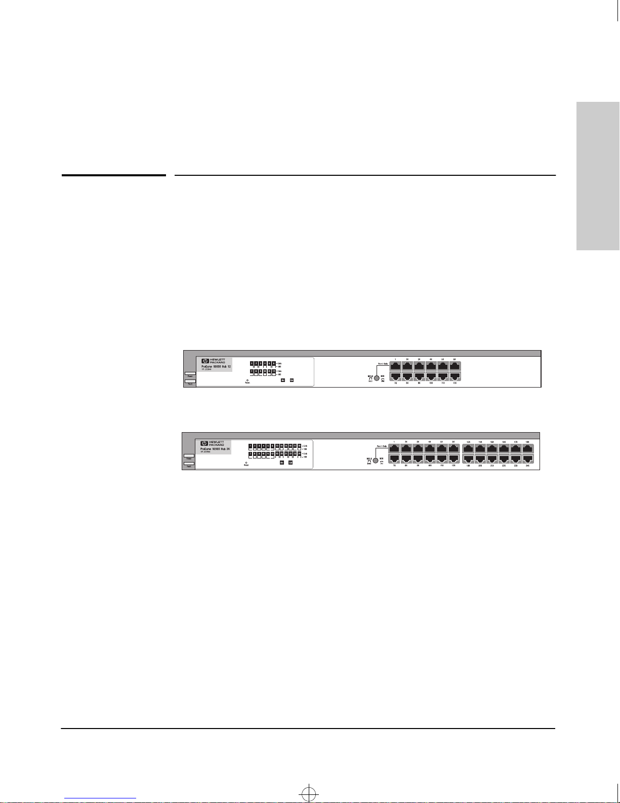
HP ProCurve J3295A 10/100 Hub 24
HP ProCurve J3294A 10/100 Hub 12
Roadhw0.bk : ROADHW1.FM Page 1 Thursday, May 28, 1998 5:40 PM
Introducing the HP ProCurve 10/100 Hubs
The HP ProCurve J3294A and HP J3295A 10/100 hubs are low-cost multiport,
dual-speed, 10- and 100Mbps repeaters that can be used to build highperformance workgroup networks. These hubs are completely autosensing
and autonegotiating devices that provide the flexibility of adjusting to
different speed settings. The hubs are always half-duplex. This capability is
present provided that the connecting device is autonegotiation-capable or
already configured to half-duplex, and will autonegotiate with other
autonegotiating or half-duplex devices.
1
Introducing the HP ProCurve
10/100 Hubs
The two hub models are:
Throughout this manual, these hubs will be abbreviated as the HP 10/100 hubs.
The HP 10/100 Hub 12 and Hub 24 have twelve and twenty-four dual-speed,
10/100Base-T ports, respectively.
With these hubs you can build a network infrastructure by connecting the hubs
to other hubs, switches, or routers, or you can connect computers, printers,
and servers to these hubs to provide dedicated 10- or 100Mbps bandwidth to
those devices.
1-1
Page 7
Roadhw0.bk : ROADHW1.FM Page 2 Thursday, May 28, 1998 5:40 PM
Introducing the HP ProCurve 10/100 Hubs
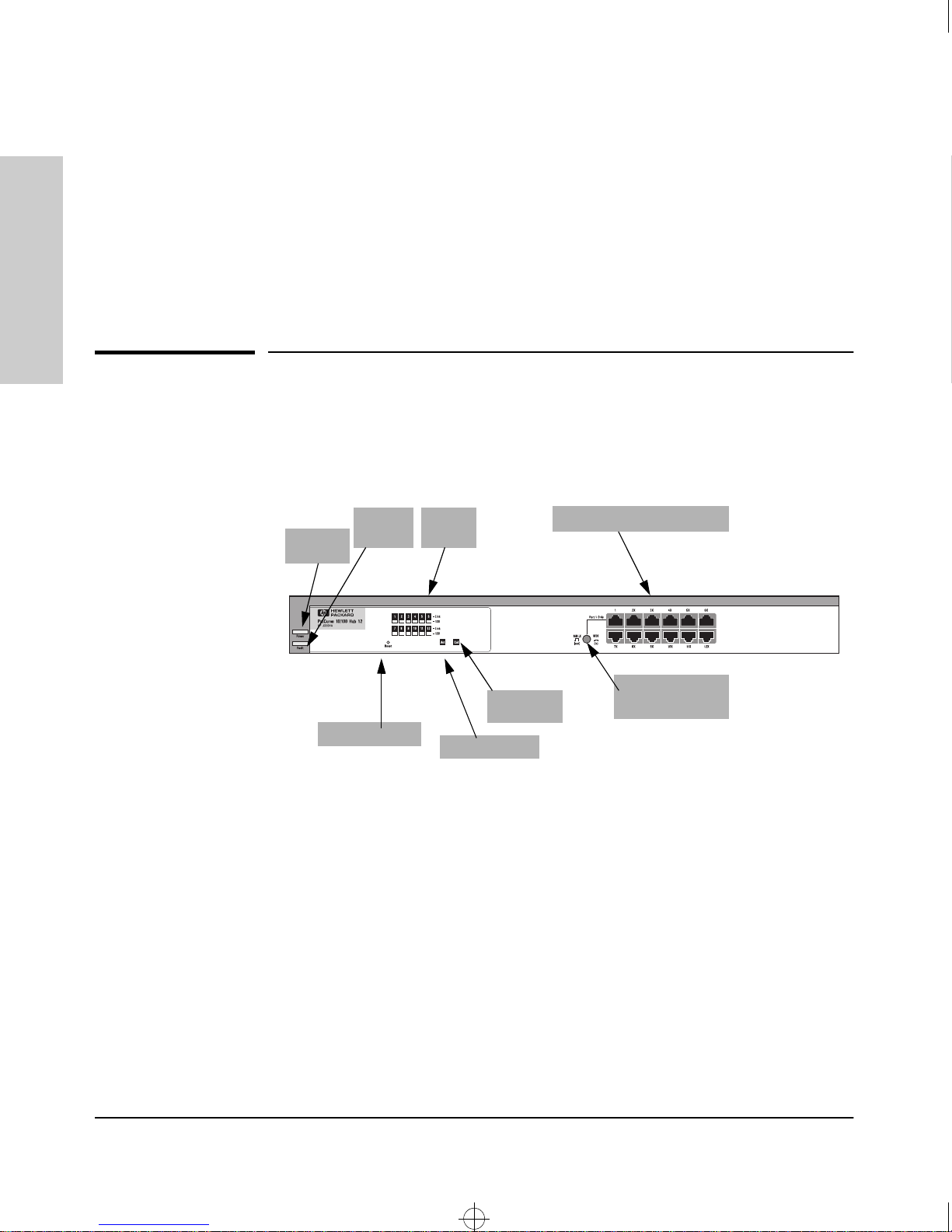
Front of the Hubs
This chapter describes your HP 10/100 hubs:
■ Front and back of the hubs
■ Network Ports
■ Port and Hub LEDs
■ Features
10/100 Hubs
■ Hub operation overview
Introducing the HP ProCurve
Front of the Hubs
Power
LED
Fault
LED
Reset button
Port
LEDs
Activity LED
Collision
LED
10/100Base-T RJ-45 ports
MDI/MDI-X
Button for Port 1
1-2
Page 8
Roadhw0.bk : ROADHW1.FM Page 3 Thursday, May 28, 1998 5:40 PM
Introducing the HP ProCurve 10/100 Hubs
Front of the Hubs
Network Ports
The HP 10/100 Network Ports are as follows:
12 or 24 10/100Base-T RJ-45 ports
■
■ one MDI/MDI-X port (port 1).
All the fixed twisted-pair ports are wired as MDI-X. Therefore, to connect end
nodes or other MDI-type devices to these ports, use “straight-through” twistedpair cable; to connect hubs, switches, or other MDI-X-type devices to these
ports, use “crossover” twisted-pair cable. See Appendix B, “Cables and
Connectors” for descriptions of these cables. If you only have straight-through
cable, you can use port 1 with the MDI button depressed to connect hubs with
switches and other hubs. The MDI button crosses the cable pairs so that the
Transmit and Receive pins on connecting devices exchange signals correctly.
Port LED Types
There are two types of port LEDs:
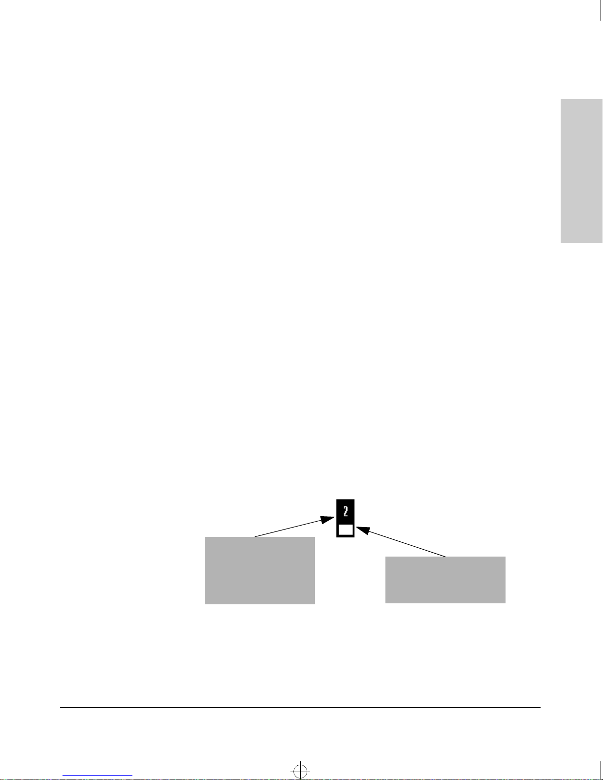
Link. This LED highlights the port number. When lit, these LEDs indicate the
port has detected another device. If the 100 LED is not lit, then the Link LED
indicates a connection to an attached 10Base-T device.
Introducing the HP ProCurve
10/100 Hubs
100. This LED highlights the rectangle LED under the Link LED. When lit,
these LEDs indicate the port is connected to an attached device operating at
100Mbps. The following figure shows an HP 10/100 LED operating at 100Mbps.
See the following sections for more LED detail.
Link LED. Indicates
whether the port has
detected an attached
device. If the 100 LED is not
lit, then the device is
operating at 10Mbps
100 LED. Indicates whether
the device connected to this
port was detected to be
100Mbps.
1-3
Page 9
Roadhw0.bk : ROADHW1.FM Page 4 Thursday, May 28, 1998 5:40 PM
Introducing the HP ProCurve 10/100 Hubs
Front of the Hubs
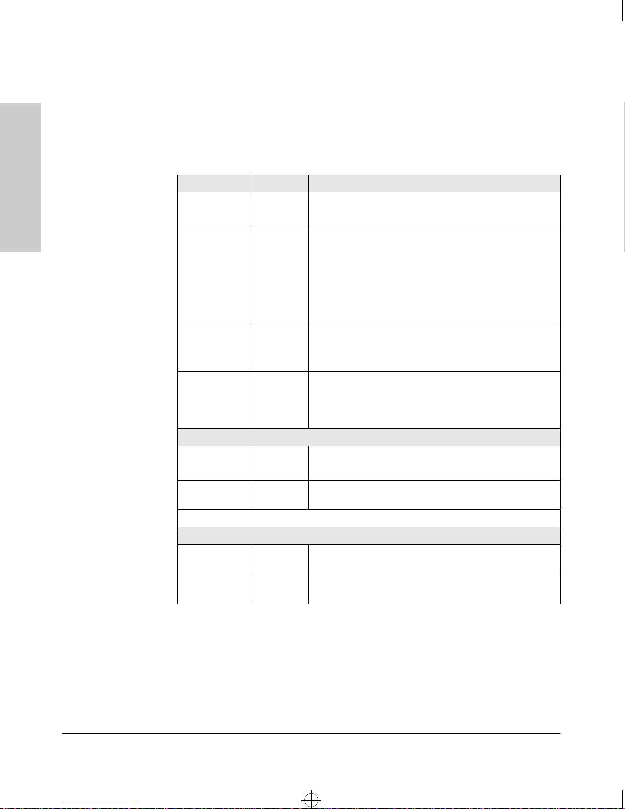
LEDs for the 10/100Base-T Hubs
To see what the LEDs for the HP 10/100 hubs do, see the following table. For
a more extended view of the LEDs, see the table under the section “LED
Combinations.”
Hub Status LED State Meaning
10/100 Hubs
Introducing the HP ProCurve
Power (Green) On The hub is receiving power.
Off The hub is NOT receiving power.
Fault (Orange) Off The normal state. Indicates that there are no fault conditions
on the hub.
On The hub is in self test after being powered on or reset. If on
for a prolonged time (after three seconds), the hub has failed
its self test.
Slow* A port has been partitioned. The Link LED of the partitioned
port also blinks.
Activity (Green) On/Blinking The hub is receiving packets. If it appears as solid, packet
traffic is heavy.
Off The hub is not receiving packets from any attached device.
Collision
(Orange)
Link LEDs
Link On The port detects an attached device.
* The slow blink behavior is a regular pulse once every 1.6 seconds, approximately.
100 LEDs
100Mbps
Indicator LED
On/Blinking The hub has detected two or more packets on the hub have
run into each other on the hub, blocking successful. If the
LED is on solid, a heavy collision rate is occurring.
Off No collisions have been detected on the hub.
Off The port has not detected another device.
Slow Blink* The port has been autopartitioned due to excessive
collisions.
On The port is operating at 100Mbps.
Off If the Link LED is lit, the port is operating at 10Mbps.
If the Link LED is not lit, no attached device is detected.
1-4
Page 10
Roadhw0.bk : ROADHW1.FM Page 5 Thursday, May 28, 1998 5:40 PM
Introducing the HP ProCurve 10/100 Hubs
Back of the Hubs
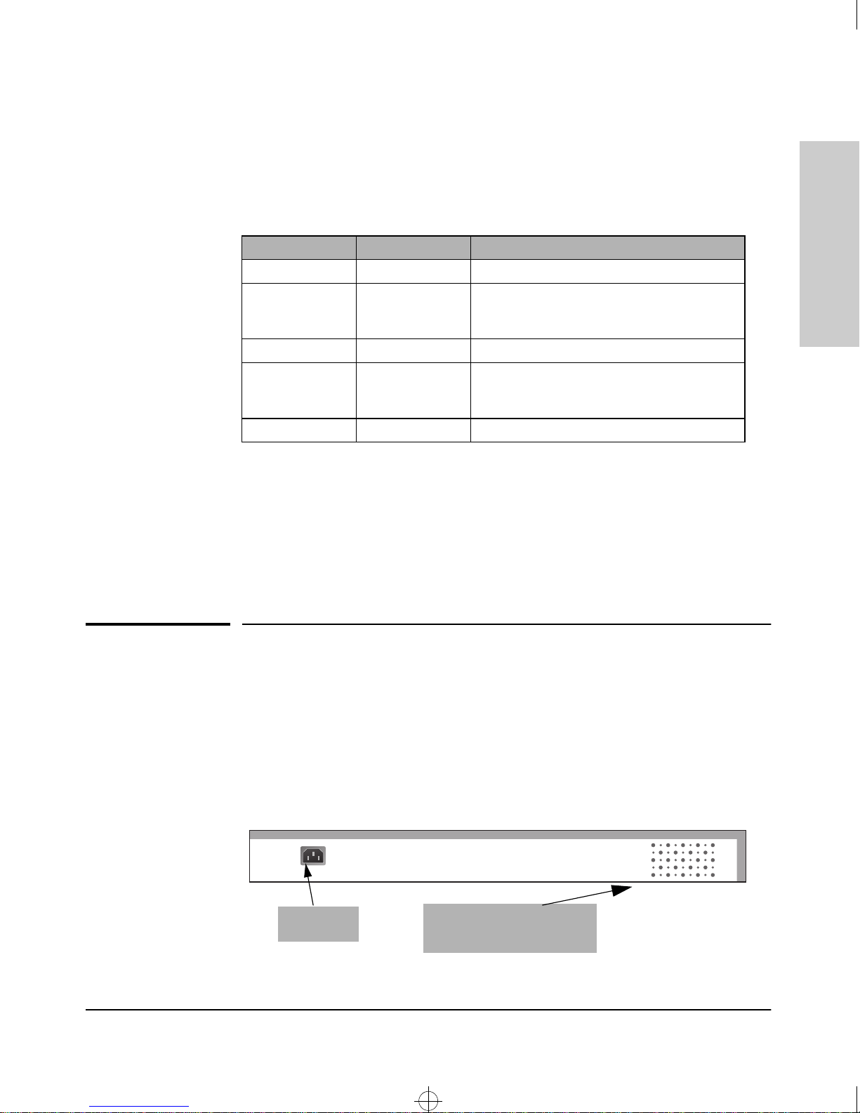
LED Combinations
The following table shows the kind of activity that occurs in various LED
illumination combinations:
Link LED 100 LED What is Happening
On Off The port is operating at 10Mbps.
On - Slow Blink Off The port is operating in 10Mbps mode, but has
been partitioned due to excessive collisions.
The Fault LED will also blink.
On On The port is operating at 100Mbps.
On - Slow Blink On - Slow Blink The port is operating in100Mbps mode, but has
been partitioned due to excessive collisions.
The Fault LED will also blink.
Off Off The port does not detect another device.
Reset Button
This button is used to reset the hub while it is powered on. This action clears
any temporary error conditions that may have occurred, restarts the hub and
executes the hub self test. A typical instance of where you might use the Reset
button is in the event of a hub malfunction or error condition.
Introducing the HP ProCurve
10/100 Hubs
Back of the Hubs
Power Connector
The 10/100 hubs do not have a power switch; they are powered on when
connected to an active AC power source. The hubs automatically adjust to
various voltages (depending on the country) between 100-127 and 200-240
volts and either 50 or 60 Hz. There are no voltage range settings required.
AC Power
Connector
Cooling vents - make sure
these are not obstructed for
proper hub operation
1-5
Page 11
Roadhw0.bk : ROADHW1.FM Page 6 Thursday, May 28, 1998 5:40 PM
Introducing the HP ProCurve 10/100 Hubs
Features
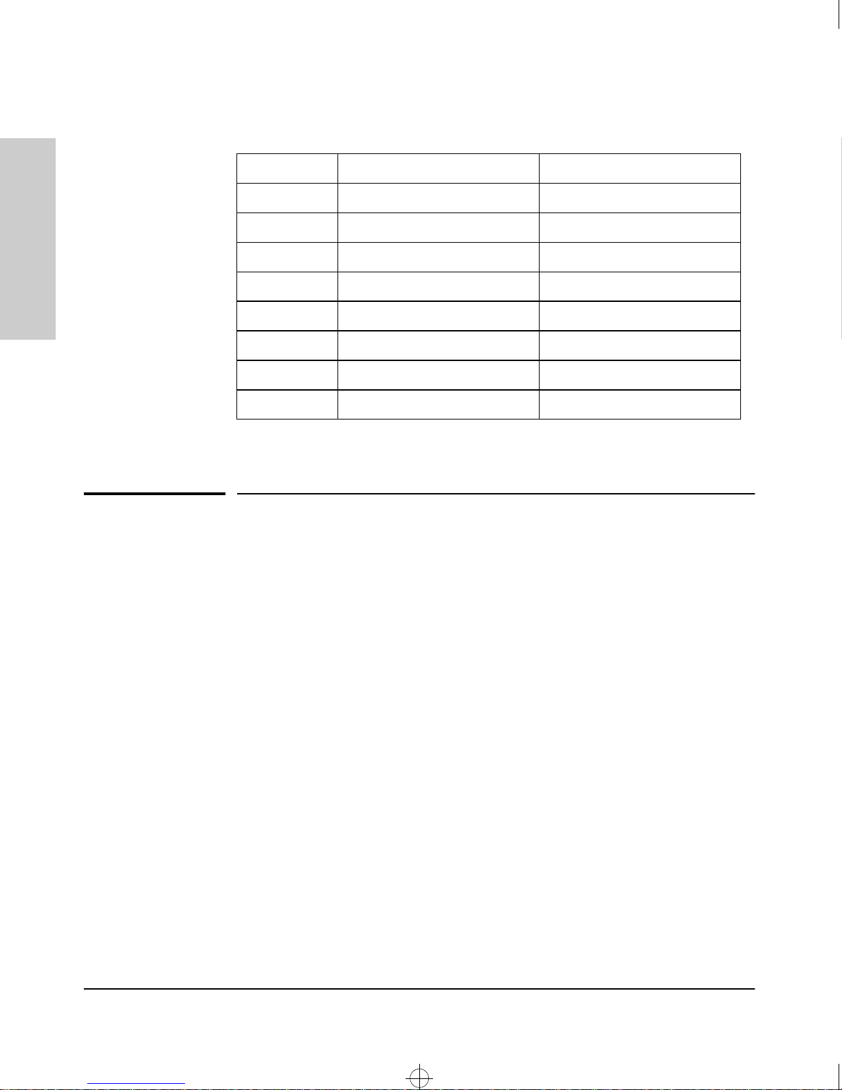
The power cords and levels of power for the hub are listed below.
Country Power Cord Part Number Voltage/Hz Level
China 8120-8377 220-240 Vac, 50 Hz
USA 8120-6805 110-127 Vac, 60 Hz
Europe 8120-6802 230 Vac, 50 Hz
10/100 Hubs
Australia 8120-6803 220-240 Vac, 50 Hz
Introducing the HP ProCurve
Japan 8120-6804 100 Vac, 50/60 Hz
UK 8120-6801 220-240 Vac, 50 Hz
Switzerland 8120-6807 230 Vac, 50 Hz
Denmark 8120-6806 230 Vac, 50 Hz
Features
The features of the10/100 hubs include:
12 or 24 Ethernet 10/100Base-TX ports with RJ-45 connectors.
■
■ plug-and-play networking—all ports are enabled—just connect the
network cables to active Ethernet or Fast Ethernet network devices and
your network is operational.
■ all ports are autonegotiation-capable.
■ 12 or 24 Link LEDs with companion 100Mbps LEDs.
■ push-button MDI/MDI-X selection.
■ rack- or wall-mountable.
1-6
Page 12

Roadhw0.bk : ROADHW2.FM Page 1 Thursday, May 28, 1998 5:40 PM
Installing the Hub
The HP J3294A and HP J3295A 10/100 hubs are easy-to-install units. Each
comes with an accessory kit (HP P/N 5183-7210) that includes the brackets
for mounting the hub in a standard 19-inch telco rack or an equipment cabinet,
or on a wall, and it comes with rubber feet so it can be securely located on a
horizontal surface. The brackets are designed to allow mounting the hub in a
variety of orientations.
2
This chapter shows you how to install your 10/100 hub.
Included Parts
The 10/100 hub has the following components shipped with it:
■
HP ProCurve 10/100 Hubs Installation Guide (5967-2280), this manual
■ Customer Support/Warranty booklet (5967-2242)
■ Accessory kit (5183-7210)
• two mounting brackets
• four 10 mm M4 screws to attach the mounting brackets to the hub
• four 5/8-inch number 12-24 screws to attach the hub to a rack
• four rubber feet
Power cord, one of the following:
■
Australia/New Zealand
United Kingdom
China
Continental Europe
Denmark
Japan
Switzerland
United States/Canada/Mexico
(8120-6803)
(8120-6801)
(8120-8377)
(8120-6802)
(8120-6806)
(8120-6804)
(8120-6807)
(8120-6805)
Installing the Hub
2-1
Page 13

Roadhw0.bk : ROADHW2.FM Page 2 Thursday, May 28, 1998 5:40 PM
Installing the Hub
Installation Summary
Installation Summary
Follow these easy steps to install your hub. The rest of this chapter provides
details on these steps.
1. Prepare the installation site. Make sure that the physical environment
into which you will be installing the hub is properly prepared including
having the correct network cabling ready to connect to the hub, and
having a good location for the hub. Please see page 2-4 for some
installation precautions.
2. Verify that the hub passes self test. This is a simple process of plugging
the hub into a power source and observing that the LEDs on the hub’s
front panel show correct operation.
Installing the Hub
3. Mount the hub. The hub can be mounted in a 19-inch telco rack, in an
equipment cabinet, on a wall, or on a horizontal surface.
4. Connect power to the hub. Once the hub is mounted, plug it in to the
nearby main power source.
5. Connect the network devices. Using the appropriate network cables,
connect other hubs, switches, routers, computers, servers, printers, and
other network devices to the hub ports.
At this point, the hub is fully installed and your network should be up and
running. See the rest of this chapter if you need more detailed information on
any of these installation steps.
2-2
Page 14

Roadhw0.bk : ROADHW2.FM Page 3 Thursday, May 28, 1998 5:40 PM
Installation Precautions
The following are power requirement precautions.
• If your installation requires a different power cord than the one supplied with the hub,
be sure to use a power cord displaying the mark of the safety agency that defines the
regulations for power cords in your country. The mark is your assurance that the power
cord can be used safely with the hub
• Do not install the hub in an environment where the operating ambient temperature might
exceed 55°C (131°F).
• The hub does not have a power switch; it is powered on when the power cord is plugged
in. The hub's power supply automatically adjusts to any AC power source between 100127 volts and 200-240 volts. There are no voltage range settings to configure.
• When installing the hub, note that the AC outlet must be installed near the equipment
and should be easily accessible.
Installing the Hub
Installation Summary
Installing the Hub
The following are mounting precautions:
• The rack or cabinet should be adequately secured to prevent it from becoming unstable
and/or falling over. The hub should be mounted in a position toward the bottom of the
rack for stability and to make it easier to stack the other hubs on top.
• Before mounting a hub, plan its location and orientation relative to other devices and
equipment. Also consider the cabling that will be attached to the hub and the ports that
will be used. Verify that there is room for the grouped cables to trail out from the side of
the hub. Allow at least 2.54 cm (1 inch) in the front of the hub. In the back of the hub,
allow at least 3.8 cm (1 1/2 inches) of space for the power cord.
• Ensure that the HP 10/100Base-TX Hub does not overload the power circuits, wiring,
and over-current protection. To determine the possibility of overloading the supply
circuits, add together the amperage ratings from the nameplates of all your hubs (and
other equipment) installed on the same circuits and compare the total with the rating
limits for the supply circuits.
• Make sure that the power source circuits are properly grounded, then use the supplied
power cord to connect the HP 10/100Base-TX Hubs to the circuit. See the Safety
Statements in this chapter.
• Do not block airflow around the sides and the back of the unit.
2-3
Page 15

Roadhw0.bk : ROADHW2.FM Page 4 Thursday, May 28, 1998 5:40 PM
Installing the Hub
Installation Summary
1. Prepare the Installation Site
■ Cabling Infrastructure - Ensure that the cabling infrastructure meets
the necessary network specifications. See the following table for cable
types and lengths, and see Appendix B, “Cables and Connectors” for more
information:
Port Type Cable Type Length Limits
Installing the Hub
10Base-T category 3, 4, or 5, four-
pair, 100 ohm UTP
(unshielded twisted-pair)
100Base-TX category 5, 100-ohm UTP Cable lengths depend on the type of device
■ Installation Precautions -
Up to 100 meters for category 3 or 4, and
150 meters for category 5.
See the section covering twisted pair
cabling in Appendix B, “Cables and
Connectors” for more information.
connected and on the network topology.
See the section covering twisted pair
cabling in Appendix B, “Cables and
Connectors” for more information.
• Please see the Safety Statements at the end of this
manual.
• Before installing the hub, plan its location and orientation relative to
other devices and equipment. In the front of the hub, leave at least 3
inches (7.6 cm) of space for the twisted-pair cabling. In the back,
leave at least 1 1/2 inches (3.8 cm) of space for the power cord.
• Caution: Ensure that the hub does not overload the power circuits,
wiring, and over-current protection. To determine the possibility of
overloading the supply circuits, add together the ampere ratings of all
devices installed on the same circuit as the hub and compare the total
with the rating limit for the circuit. The maximum ampere ratings are
usually printed on the devices near the AC power connectors.
• Caution: Ensure that the power source circuits are properly
grounded. See the Safety Statements at the end of this manual.
• Do not install the hub in an environment where the operating ambient
temperature might exceed 55°C (131°F).
• Make sure the air flow around the sides and back of the hub is not
restricted.
2-4
Page 16
Roadhw0.bk : ROADHW2.FM Page 5 Thursday, May 28, 1998 5:40 PM
2. Verify the Hub Operates Correctly
Before mounting the hub in its network location, you should first verify that
it is working properly by plugging it into a power source and verifying that it
passes its self test.
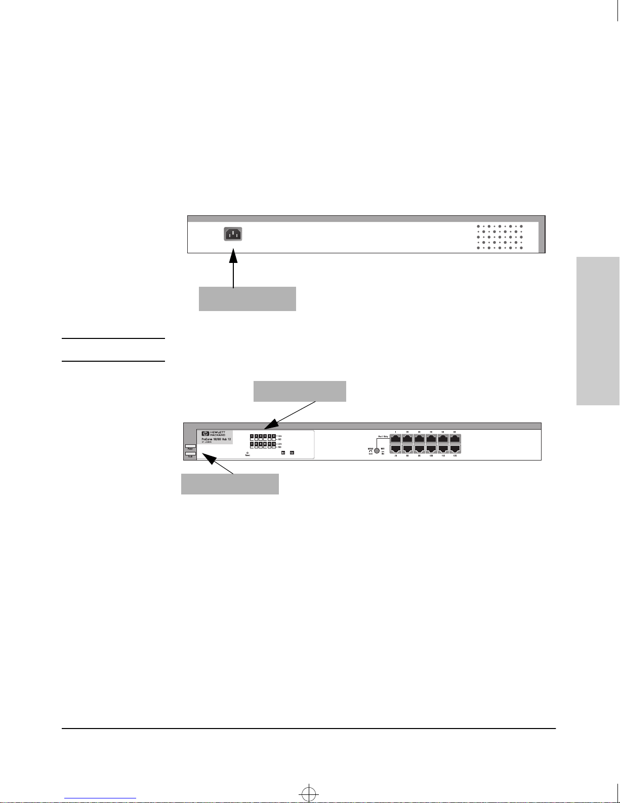
1. Connect the power cord supplied with the hub to the power connector on
the back of the hub, and then into a properly grounded electrical outlet.
Installing the Hub
Installation Summary
Note
Connect power cord
to power connector
2. Check the LEDs on the hub.
Hub Port LEDs
Power and Fault LEDs
When the hub is powered on, it performs its diagnostic self test. The self
test occurs by all port LEDs illuminating and going off. The self-test takes
approximately three seconds to complete.
LED Behavior:
Installing the Hub
During the self test:
• Initially, all the hub and port LEDs are on.
• After three seconds, the port LEDs go off.
When the self test completes successfully:
• The large Power LED stays on.
• The large Fault LED goes off.
• The port LEDs go into their normal operational mode.
2-5
Page 17
Roadhw0.bk : ROADHW2.FM Page 6 Thursday, May 28, 1998 5:40 PM
Installing the Hub
Installation Summary
If the LED display is different than what is described above, especially if
the Fault LED stays on for more than 3 seconds, the self test has not
completed correctly. Refer to chapter 3, “Troubleshooting” for diagnostic
help.
3. Mount the Hub
Make sure you are ready to mount the hub in a stable location. The hub can
be mounted in these ways:
■ in a rack or cabinet
■ on the wall
on a horizontal surface
■
Installing the Hub
Rack or Cabinet Mounting
The hub is designed to be mounted in any EIA-standard 19-inch telco rack or
in an equipment cabinet such as a server cabinet.
For safe operation, please read the mounting precautions in
the section, “Installation Precautions” earlier in this chapter before
mounting a hub.
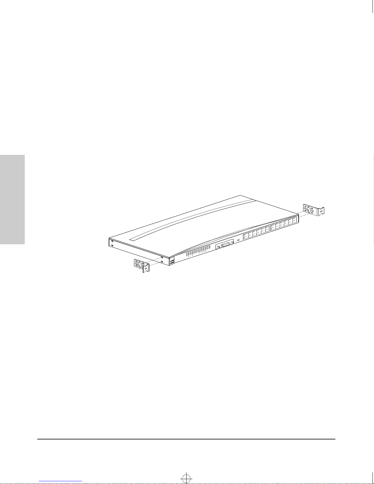
1. Use a #1 Phillips (cross-head) screwdriver and attach the mounting
brackets to the hub with the included 10-mm M4 screws.
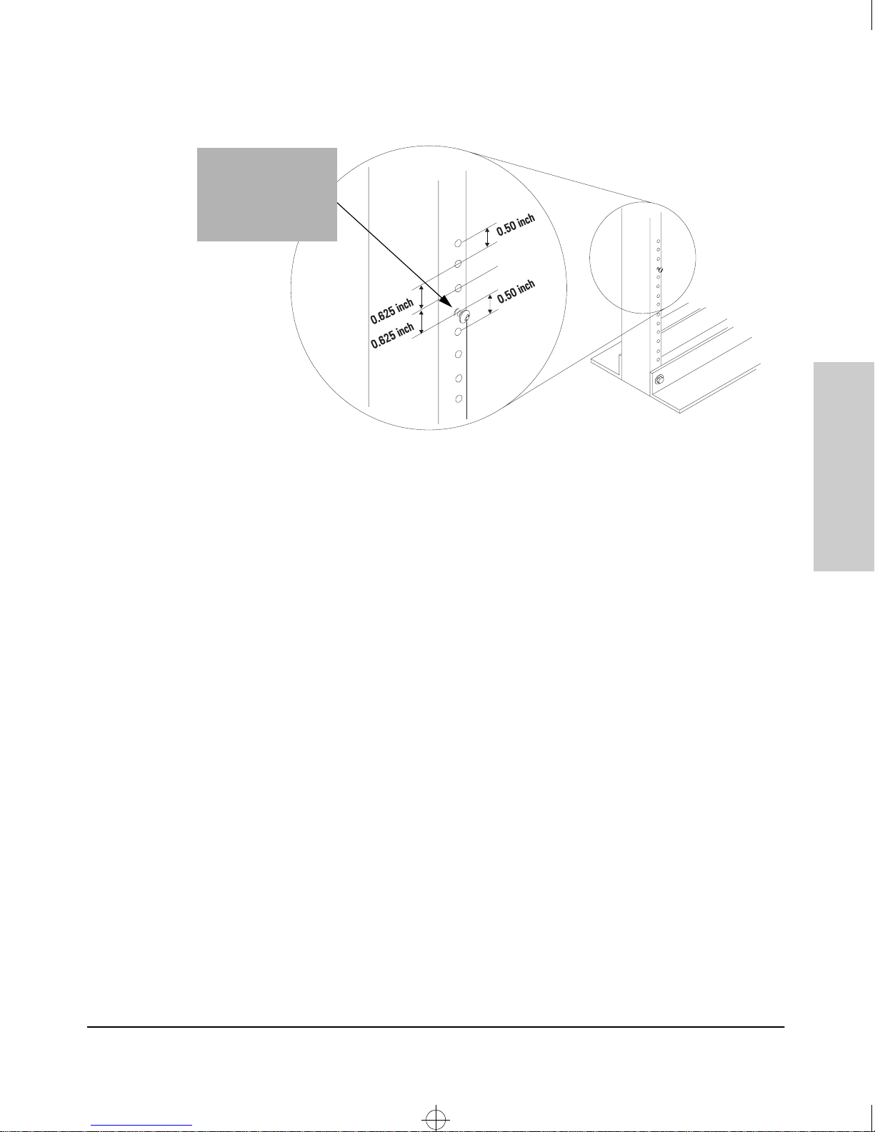
2. Partially install a screw (5/8-inch number 12-24) into the top hole of a pair
of holes that are 0.5 inches apart in each rack/cabinet upright as shown
in the illustration below. Ensure that the screws are at the same level in
each upright.
2-6
Page 18
Roadhw0.bk : ROADHW2.FM Page 7 Thursday, May 28, 1998 5:40 PM
Partially install a
screw into the top
hole of a close
(0.5-inch) pair
on both sides
of the rack
Installing the Hub
Installation Summary
Installing the Hub
.
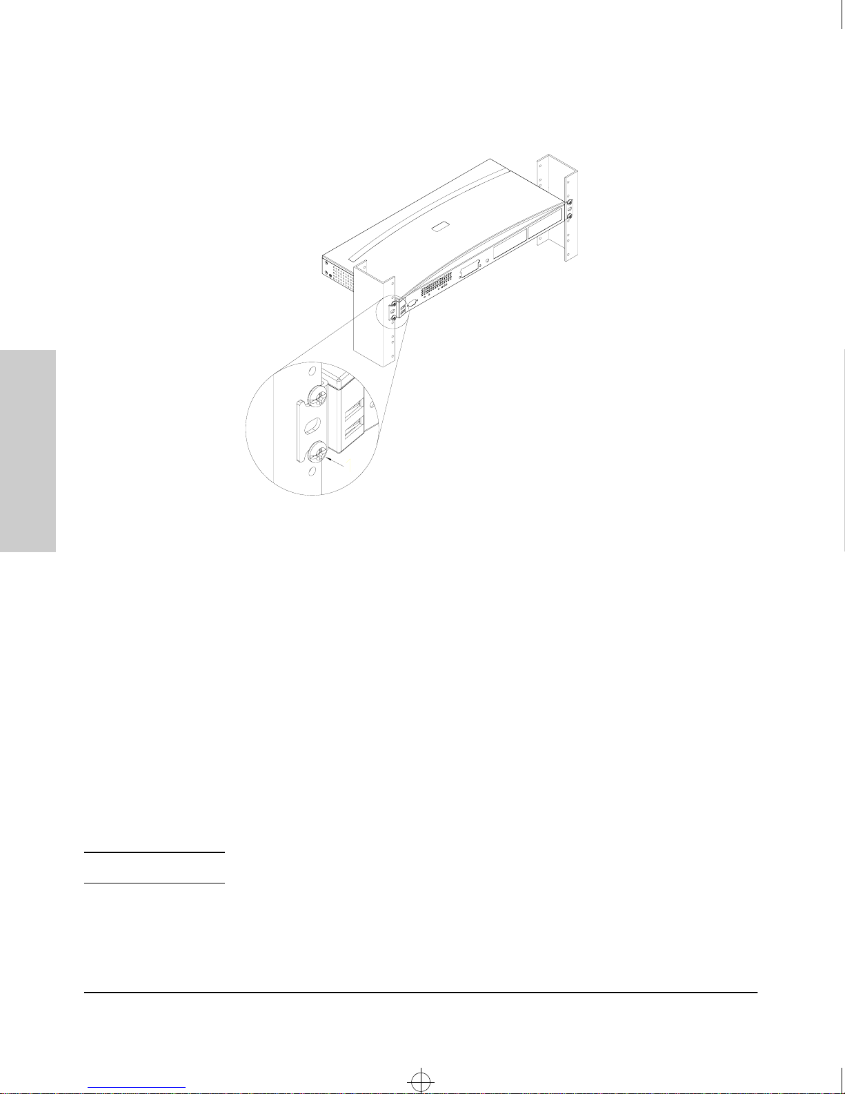
3. Place the hub in the rack and lower it so the notches in the bottom of the
bracket slide onto the screws. Tighten these screws-be careful not to
overtighten them.
4. Install the other number 12-24 screw into the upper hole in each bracket.
Tighten these screws-be careful not to overtighten them.
2-7
Page 19
Roadhw0.bk : ROADHW2.FM Page 8 Thursday, May 28, 1998 5:40 PM
Installing the Hub
Installation Summary
Installing the Hub
Note
Wall Mounting
You can mount the hub on a wall. Note that the hub should be mounted only
to a wall or wood surface that is at least 1/2-inch plywood or its equivalent.
1. Use a #1 Phillips (cross-head) screwdriver and attach the mounting
brackets to the hub with the included 10-mm M4 screws.
2. Attach the hub to the wall or wood surface with 5/8-inch number 12 wood
screws (not included}.
Horizontal Surface Mounting
Place the hub on a table or other horizontal surface. Use a sturdy surface in
an uncluttered area. You may want to secure the networking cables and hub
power cord to the table leg or other part of the surface structure to help
prevent people from tripping over the cords.
Make sure the air flow is not restricted around the sides and back of the hub.
2-8
Page 20

Roadhw0.bk : ROADHW2.FM Page 9 Thursday, May 28, 1998 5:40 PM
4. Connect the Hub to a Power Source
1. Plug the included power cord into the hub’s power connector and into a
nearby AC power source.
2. Re-check the LEDs during self test. See “LED Behavior” on page 2-5.
For power precautions, see the section, “Installation Precautions” earlier in
this chapter. The HP 10/100 hubs do not have a power switch. They are
powered on when the power cord is connected to the hub and to a power
source.
5. Some Basic Troubleshooting
Installing the Hub
Installation Summary
Condition Diagnostic Tip
Port LED is
still off when
a cable is
connected
Try the following:
• For the indicated port, verify that both ends of the cabling, at the hub and
the connected device, are snug.
• Verify the connected device and hub are both powered
correctly.
• Verify that you have used the correct cable type for the connection. Twistedpair cable connections, in general, for connecting to an end node, use
“straight-through” cable; for connecting to switches or other hubs, use
“crossover” cable.
• Verify that the attached device is Autonegotiation capable or, if not, that it
is not full-duplex.
• Try using a different port or a different cable.
on
and operating
Installing the Hub
2-9
Page 21

Roadhw0.bk : ROADHW2.FM Page 10 Thursday, May 28, 1998 5:40 PM
Installing the Hub
Sample Network Topologies
Sample Network Topologies
For topology information, see the document Designing HP ProCurve Work-
group Networks, which can be found on the HP network products World Wide
Web site, http://www.hp.com/go/network_city. Also, see the Quick Reference
Card that accompanies the product for sample network topologies.
Where to Go From Here
Installing the Hub
Your hub is now correctly installed and is able to send and receive data
between end nodes, servers, and printers.
The HP 10/100 hubs are plug-and-communicate network devices requiring no
configuration.
2-10
Page 22

Roadhw0.bk : ROADHW3.FM Page 1 Thursday, May 28, 1998 5:40 PM
Troubleshooting
This chapter describes how to troubleshoot your HP 10/100 hub. This chapter
describes the following:
■ basic troubleshooting tips
diagnosing with the LEDs
■
■ Hardware Diagnostic tests
■ HP Customer Support Services
3
Basic Troubleshooting Tips
Most problems are caused by the following situations:
Incorrect hub-to-switch or hub-to-hub connections.
■
cable type.
• When connecting an MDI-X device such as a hub or most switches,
use a crossover cable. You can also use Port 1 and press the MDI
button.
• When connecting an MDI-X device to an MDI device, use a straightthrough cable.
Most switch and hub ports are wired as MDI-X ports, so for these hub-tohub or hub-to-switch connections, use a crossover cable. LAN adapters
in end nodes are normally wired as MDI ports as are some ports on hubs
and switches. For connections from the hub to these MDI ports, use a
straight-through cable. See Appendix B, “Cables and Connectors” for
pinouts and correct cable wiring for crossover and straight-through
twisted-pair cables.
Faulty cable or cable is loose.
■
connections. If they appear to be OK, try a different cable.
Look for loose or obviously faulty
Check your
Troubleshooting
3-1
Page 23

Roadhw0.bk : ROADHW3.FM Page 2 Thursday, May 28, 1998 5:40 PM
Troubleshooting
Basic Troubleshooting Tips
■ Non-standard cables. Non-standard and miswired cables may cause
network collisions and noise, and can seriously impair network performance. 100Base-T networks are more sensitive to miswired cables than
10Base-T networks. Use a new correctly-wired cable or compare your
cable to the cable in Appendix B, “Cables and Connectors” for pinouts and
correct cable wiring. A category 5 cable tester is a recommended tool for
every 100Base-T network installation.
■
Full-duplex link to the hub. Regular hub ports can only operate in halfduplex mode. If the attached device is running in full-duplex mode, it will
cause a lot of late collisions on the network, degrading performance for
all nodes.
■
100Base-T topology rules are much more restrictive than 10BaseT rules. Be aware that you may have to redo existing 10Base-T topology
for 100Base-T products.
■ When using 100Base-T devices, follow the rules for Category 5 cable
installations.
■ Some basic Class II 100Base-T Hub rules are displayed here.
• The maximum segment length for a hub-to-end node connection is
100 meters.
• You are permitted to cascade no more than two hubs.
• Do not mix Class I and Class II hubs when cascading.
• When cascading two hubs together, the maximum distance separating
them is 5 meters.
• You must use Category 5 cable installations.
■ Improper Network Topologies. It is important to make sure you have
a valid network topology. Common topology faults include excessive
cable length and excessive repeater delays between nodes. If you have
Troubleshooting
network problems after recent changes to the network, change back to
the previous topology. If you no longer experience the problems, the new
topology is probably at fault. Refer to the guide entitled Designing HP
ProCurve Workgroup Networks for topology configuration guidelines.
This guide can be found online at the HP World Wide Web site, http://
www.hp.com/go/network_city.
In addition, you should make sure that your network topology contains
no data path loops. Between any two end nodes, there should be only one
active cabling path at any time. Data path loops will cause broadcast
storms that will severely impact your network performance.
3-2
Page 24
Roadhw0.bk : ROADHW3.FM Page 3 Thursday, May 28, 1998 5:40 PM
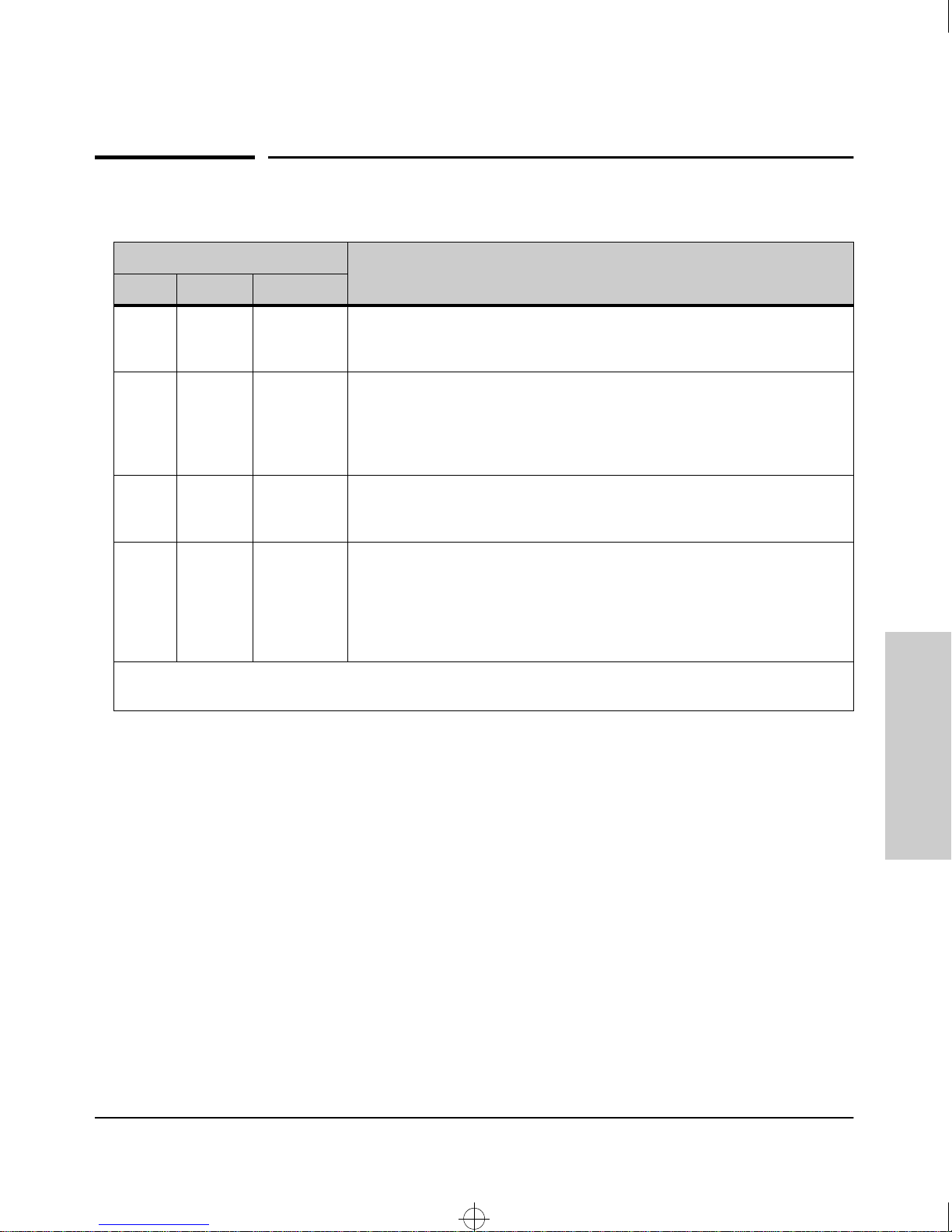
Diagnosing with the LEDs
LED patterns indicating problems Diagnostic Tips
Power Fault Port
OFF * * Check the power cord and power source. If they are OK, the hub may have to
be replaced. Contact your HP-authorized LAN dealer or HP representative for
assistance.
Troubleshooting
Diagnosing with the LEDs
ON OFF OFF when
cable first
connected
ON Flashing Flashing for
partitioned
port
ON ON for a
prolonged
period
* This LED is not important for the diagnosis.
Variable, all
may be ON
• An attached device has not been detected on the port. Check that the
cabling on the indicated port is connected properly. Faulty or improperly
wired cables are common; try a different cable.
• For the 100 Mbps autosensed ports, verify that you are using category 5, or
better, UTP cable.
The port has been autopartitioned due to excessive collisions. This usually
occurs because of bad cabling or a network loop.
A hub hardware failure was detected during self test. Self test does not
complete so the LEDs will stay on longer than 3 seconds.
Power cycle the hub. If this condition persists, the hub may have to be
replaced. Contact your HP-authorized LAN dealer or HP representative for
assistance.
Troubleshooting
3-3
Page 25

Roadhw0.bk : ROADHW3.FM Page 4 Thursday, May 28, 1998 5:40 PM
Troubleshooting
Hardware Diagnostic Tests
Hardware Diagnostic Tests
Testing the Hub by Resetting It
If you believe that the hub is not operating correctly, you can reset it to test
its circuitry and operating code. To reset a hub, either:
■ Unplug and plug back in the power cord (power cycle)
■ Press the reset button on the front of the hub
Power cycling the hub and pressing the Reset button both cause the hub to
perform its power-on self-test, which almost always will resolve any temporary operational problems.
Troubleshooting
Note
The self-test passes if the Fault LED on the front of the hub goes off after
approximately 3 seconds. If the Fault LED stays on longer than 3 seconds, the
hub may have to be replaced. Contact your HP-authorized dealer or HP
representative for assistance.
Testing Twisted-Pair Cabling
If you think the cable should work but still isn’t working, it may not be
compatible with the IEEE 802.3 Type 10Base-T or IEEE 802.3u 100Base-T
standards. The twisted-pair cables attached to the HP 10/100 hub must be
compatible with these standards.To verify that your cable is compatible with
these standards, use a qualified cable test device.
HP also offers a wire testing service. Contact your HP-authorized LAN dealer
or your local HP sales office for more information.
Make sure that you are using the correct cabling type for each connection.
The hub ports are all wired as MDI-X. For connecting end nodes and other
MDI-type devices, use “straight-through” cable. For connecting switches,
other hubs, and other MDI-X devices, use “crossover” cable. See Appendix B,
“Cables and Connectors” for the pinouts for these cables.
3-4
Page 26

Roadhw0.bk : ROADHW3.FM Page 5 Thursday, May 28, 1998 5:40 PM
HP Customer Support Services
HP Customer Support Services
If you are still having trouble with your hub, Hewlett-Packard offers support
24 hours a day, seven days a week through the use of a number of automated
electronic services. See the Warranty and Support booklet that came with your
hub for information on how to use these services to get technical support.
Your HP-authorized network reseller can also provide you with assistance,
both with services that they offer and with services offered by HP.
Troubleshooting
Troubleshooting
3-5
Page 27

Roadhw0.bk : ROADHW3.FM Page 6 Thursday, May 28, 1998 5:40 PM
Page 28

ROADHWA.FM Page 1 Wednesday, June 3, 1998 10:40 AM
Specifications
Physical
Width: 42.5 cm (17 in)
Depth: 20.3 cm (8 in)
Height: 4.36 cm (1.7 in)
A
Weight : 2.2 kg (4.8 lbs)
Electrical
The switch automatically adjusts to any voltage between 100-127 and 200-240
volts and either 50 or 60 Hz.
AC voltage: 100–127 volts 200–240 volts
Maximum current: 1.0A max 0.5A max
Frequency range: 50/60 Hz 50/60 Hz
Environmental
Operating Non-Operating
Temperature: 0°C to 55°C (32°F to 131°F) -40°C to 70°C (-40°F to 158°F)
Relative humidity:
(non-condensing)
Maximum altitude: 4.6 Km (15,000 ft) 4.6 Km (15,000 ft)
15% to 95% at 40°C (104°F) 10% to 90% at 65°C (149°F)
Specifications
A-1
Page 29

Roadhw0.bk : ROADHWA.FM Page 2 Thursday, May 28, 1998 5:40 PM
Specifications
Connectors
■ The 10/100 Mbps RJ-45 twisted-pair ports are compatible with the IEEE
802.3 and 802.3u 100Base-T standards respectively.
Safety
IEC950 (1991) + A1, A2/.EN60950 I (1992)+A1,A2
CSA950
NOM-019-SCFI-1993
UL1950
Specifications
A-2
Page 30

Roadhw0.bk : ROADHWB.FM Page 1 Thursday, May 28, 1998 5:40 PM
Cables and Connectors
This appendix lists cables that have been tested and verified for use with the
HP10/100 12 and 24 hubs. It also includes minimum pin-out information so, if
you wish to use an unlisted cable, you can verify that the cables used in your
installation are correctly wired. Note that each pin-out does not necessarily
match the pin-out for the corresponding HP cable, but cables manufactured
to follow the minimum pin-out will function correctly.
B
Cables and Connectors
Note Incorrectly wired cabling is the most common cause of problems for LAN
communications. HP recommends that you work with a qualified LAN cable
installer for assistance with your cabling requirements.
Twisted-Pair Cable/Connector Pin-Outs
The RJ-45 ports (10 Mbit/s and 100 Mbit/s, both fixed and transceiver) on the
HP 10/100 Hub 12 and Hub 24 are wired as MDI-X ports. The type of twistedpair cable you connect to these ports (either “straight through” or “crossover”)
depends on the type of device at the other end of the cable.
The basic rule is, when connecting same-type ports together (for example
MDI-X-to-MDI-X), use crossover cable; when connecting opposite-type ports
together (for example MDI-X-to-MDI), use straight-through cable.
These additional rules apply:
■ All twisted-pair wires used must be twisted through the entire length of
the cable. The wiring sequence must conform to AT&T 258A (not USOC).
See “Twisted-Pair Cable Pin Assignments” later in this appendix for a
listing of the signals used on each pin.
■ For connections to the 10 Mbit/s ports, you can use Category 3, 4, or 5
unshielded twisted-pair cable, as supported by the IEEE 802.3 Type
10Base-T standard.
■ For connections to the 100 Mbit/s ports, use Category 5 only, as supported
by the IEEE 802.3u Type 100Base-TX standard.
B-1
Page 31
Roadhw0.bk : ROADHWB.FM Page 2 Thursday, May 28, 1998 5:40 PM
Cables and Connectors
Twisted-Pair Cable/Connector Pin-Outs
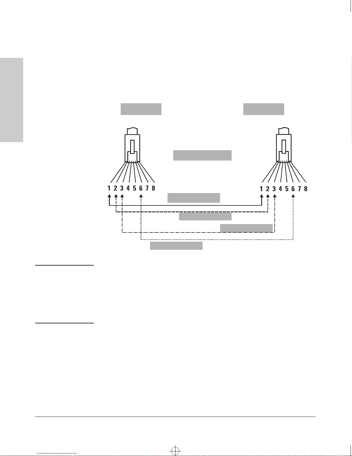
Twisted-Pair Cable for Hub (MDI-X) to
Computer (MDI) Network Connection
To connect PCs or other MDI network devices to these ports, use a “straightthrough” cable.
Connector “A” Connector “B”
Cables and Connectors
Straight-Through Cable
Note
.
White/Orange
Orange/White
White/Green
Green/White
Pins 1 and 2 on connector “A” must be wired as a twisted pair to pins 1 and 2
on connector “B”.
Pins 3 and 6 on connector “A” must be wired as a twisted pair to pins 3 and 6
on connector “B”.
Pins 4, 5, 7, and 8 are not used in this application, although they may be wired
in the cable.
B-2
Page 32
Roadhw0.bk : ROADHWB.FM Page 3 Thursday, May 28, 1998 5:40 PM
Twisted-Pair Cable/Connector Pin-Outs
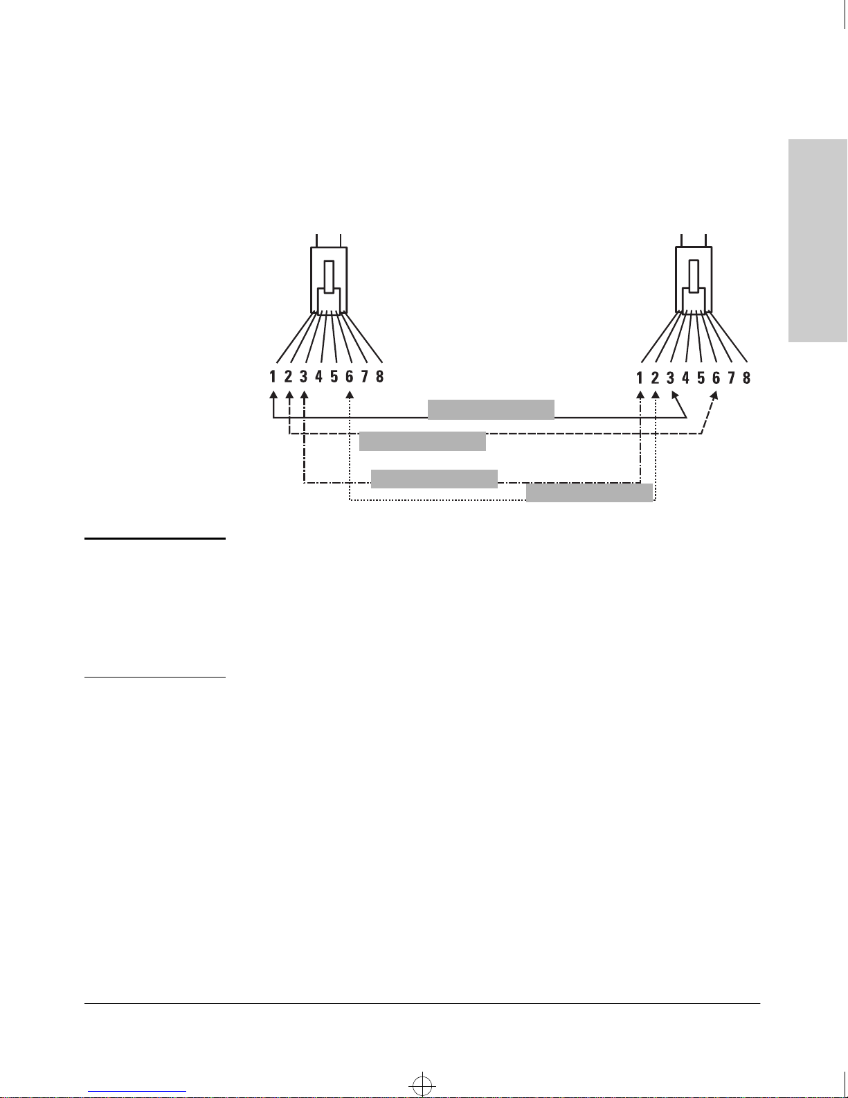
Twisted-Pair Cable for Hub (MDI-X) to
Hub or Hub (MDI-X) Network Connection
To connect hubs or switches or other MDI-X network devices to these ports,
use a “crossover” cable.
Cables and Connectors
Cables and Connectors
Note
.
Connector “A”
Crossover Cable
White/Orange
Orange/White
White/Green
Connector “B”
Green/White
Pins 1 and 2 on connector “A” must be wired as a twisted pair to pins 3 and 6
on connector “B”.
Pins 3 and 6 on connector “A” must be wired as a twisted pair to pins 1 and 2
on connector “B”.
Pins 4, 5, 7, and 8 are not used in this application, although they may be wired
in the cable.
B-3
Page 33
Roadhw0.bk : ROADHWB.FM Page 4 Thursday, May 28, 1998 5:40 PM
Cables and Connectors
Twisted-Pair Cable/Connector Pin-Outs
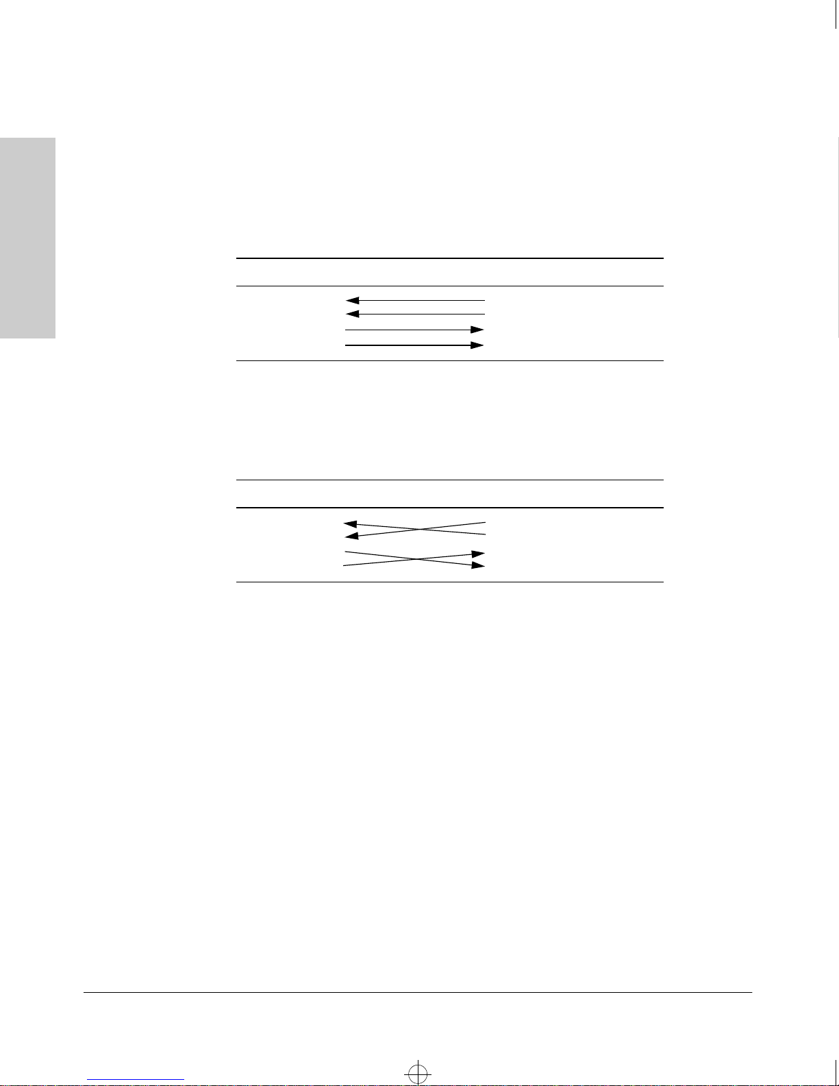
Twisted-Pair Cable Pin Assignments
Twisted-Pair Straight-Through Cable
Hub End (MDI-X) Computer, Transceiver, or
Other MDI Port End
Signal Pins Pins Signal
Cables and Connectors
(receive +)
(receive -)
(transmit +)
(transmit -
1
2
3
6
1
2
3
6
(transmit +)
(transmit -)
(receive +)
(receive -)
Twisted-Pair Cross-Over Cable
Hub End (MDI-X) Hub or Hub Port, or Other
MDI-X Port End
Signal Pins Pins Signal
(receive +)
(receive -)
(transmit +)
(transmit -)
1
2
3
6
6
3
2
1
(transmit -)
(transmit +)
(receive -)
(receive +)
B-4
Page 34

Roadhw0.bk : ROADHWC.FM Page 1 Thursday, May 28, 1998 5:40 PM
Safety and EMC Regulatory Statements
Safety Information
Documentation reference symbol. If the product is marked with this
!
WARNING A WARNING in the manual denotes a hazard that can cause injury
symbol, refer to the product documentation to get more information
about the product.
or death.
C
Safety and EMC Regulatory
Statements
CAUTION A CAUTION in the manual denotes a hazard that can damage
equipment.
Do not proceed beyond a WARNING or CAUTION notice until you
have understood the hazardous conditions and have taken appropriate steps.
Grounding
These are safety class I products and have protective earthing terminals. There
must be an uninterruptible safety earth ground from the main power source
to the product's input wiring terminals, power cord, or supplied power cord
set. Whenever it is likely that the protection has been impaired, disconnect
the power cord until the ground has been restored.
For LAN cable grounding:
■ If your LAN covers an area served by more than one power distribution
system, be sure their safety grounds are securely interconnected.
■ LAN cables may occasionally be subject to hazardous transient voltages
(such as lightning or disturbances in the electrical utilities power grid).
Handle exposed metal components of the network with caution.
Servicing
There are no user-serviceable parts inside these products. Any servicing,
adjustment, maintenance, or repair must be performed only by service-trained
personnel.
These products do not have a power switch; they are powered on when the
power cord is plugged in.
C-1
Page 35

Roadhw0.bk : ROADHWC.FM Page 2 Thursday, May 28, 1998 5:40 PM
Safety and EMC Regulatory Statements
Informations concernant la sécurité
Informations concernant la sécurité
Symbole de référence à la documentation. Si le produit est marqué de
!
WARNING Dans la documentation, un WARNING indique un danger susceptible
CAUTION Un texte de mise en garde intitulé CAUTION indique un danger suscep-
ce symbole, reportez-vous à la documentation du produit afin d'obtenir
des informations plus détaillées.
d'entraîner des dommages corporels ou la mort.
tible de causer des dommages à l'équipement.
Ne continuez pas au-delà d'une rubrique WARNING ou CAUTION
avant d'avoir bien compris les conditions présentant un danger et pris
les mesures appropriées.
Statements
Safety and EMC Regulatory
Cet appareil est un produit de classe I et possède une borne de mise à la terre. La source
d'alimentation principale doit être munie d'une prise de terre de sécurité installée aux
bornes du câblage d'entrée, sur le cordon d'alimentation ou le cordon de raccordement
fourni avec le produit. Lorsque cette protection semble avoir été endommagée,
débrancher le cordon d'alimentation jusqu'à ce que la mise à la terre ait été réparée.
Mise à la terre du câble de réseau local:
■
si votre réseau local s'étend sur une zone desservie par plus d'un système de
distribution de puissance, assurez-vous que les prises de terre de sécurité
soient convenablement interconnectées.
■
Les câbles de réseaux locaux peuvent occasionnellement être soumis à des
surtensions transitoires dangereuses (telles que la foudre ou des perturbations dans le réseau d'alimentation public). Manipulez les composants
métalliques du réseau avec précautions.
Aucune pièce contenue à l'intérieur de ce produit ne peut être réparée par l'utilisateur.
Tout dépannage, réglage, entretien ou réparation devra être confié exclusivement à un
personnel qualifié.
Cet appareil ne comporte pas de commutateur principal ; la mise sous tension est
effectuée par branchement du cordon d'alimentation.
C-2
Page 36

Roadhw0.bk : ROADHWC.FM Page 3 Thursday, May 28, 1998 5:40 PM
Safety and EMC Regulatory Statements
Hinweise zur Sicherheit
Symbol für Dokumentationsverweis. Wenn das Produkt mit diesem
!
WARNING Symbol für Dokumentationsverweis. Wenn das Produkt mit diesem
Symbol markiert ist, schlagen Sie bitte in der Produktdokumentation
nach, um mehr Informationen über das Produkt zu erhalten.
Symbol markiert ist, schlagen Sie bitte in der Produktdokumentation
nach, um mehr Informationen über das Produkt zu erhalten.
Hinweise zur Sicherheit
CAUTION Symbol für Dokumentationsverweis. Wenn das Produkt mit diesem
Symbol markiert ist, schlagen Sie bitte in der Produktdokumentation
nach, um mehr Informationen über das Produkt zu erhalten.
Fahren Sie nach dem Hinweis WARNING oder CAUTION erst fort,
nachdem Sie den Gefahrenzustand verstanden und die entsprechenden Maßnahmen ergriffen haben.
Dies ist ein Gerät der Sicherheitsklasse I und verfügt über einen schützenden Erdungsterminal. Der Betrieb des Geräts erfordert eine ununterbrochene Sicherheitserdung
von der Hauptstromquelle zu den Geräteingabeterminals, den Netzkabeln oder dem
mit Strom belieferten Netzkabelsatz voraus. Sobald Grund zur Annahme besteht, daß
der Schutz beeinträchtigt worden ist, das Netzkabel aus der Wandsteckdose herausziehen, bis die Erdung wiederhergestellt ist.
Für LAN-Kabelerdung:
■
Wenn Ihr LAN ein Gebiet umfaßt, das von mehr als einem Stromverteilungssystem beliefert wird, müssen Sie sich vergewissern, daß die
Sicherheitserdungen fest untereinander verbunden sind.
■
LAN-Kabel können gelegentlich gefährlichen Übergangsspannungen ausgesetzt werden (beispielsweise durch Blitz oder Störungen in dem
Starkstromnetz des Elektrizitätswerks). Bei der Handhabung exponierter
Metallbestandteile des Netzwerkes Vorsicht walten lassen.
Safety and EMC Regulatory
Statements
Dieses Gerät enthält innen keine durch den Benutzer zu wartenden Teile. Wartungs-,
Anpassungs-, Instandhaltungs- oder Reparaturarbeiten dürfen nur von geschultem
Bedienungspersonal durchgeführt werden.
Dieses Gerät hat keinen Netzschalter; es wird beim Anschließen des Netzkabels
eingeschaltet.
C-3
Page 37

Roadhw0.bk : ROADHWC.FM Page 4 Thursday, May 28, 1998 5:40 PM
Safety and EMC Regulatory Statements
Considerazioni sulla sicurezza
Considerazioni sulla sicurezza
Simbolo di riferimento alla documentazione. Se il prodotto è contras-
!
WARNING La dicitura WARNINGdenota un pericolo che può causare lesioni o
CAUTION La dicituraCAUTION denota un pericolo che può danneggiare le
segnato da questo simbolo, fare riferimento alla documentazione sul
prodotto per ulteriori informazioni su di esso.
morte.
attrezzature.
Non procedere oltre un avviso di WARNING o di CAUTIONprima di
aver compreso le condizioni di rischio e aver provveduto alle misure
del caso.
Statements
Safety and EMC Regulatory
Questo prodotto è omologato nella classe di sicurezza I ed ha un terminale protettivo
di collegamento a terra. Dev'essere installato un collegamento a terra di sicurezza, non
interrompibile che vada dalla fonte d'alimentazione principale ai terminali d'entrata,
al cavo d'alimentazione oppure al set cavo d'alimentazione fornito con il prodotto.
Ogniqualvolta vi sia probabilità di danneggiamento della protezione, disinserite il cavo
d'alimentazione fino a quando il collegaento a terra non sia stato ripristinato.
Per la messa a terra dei cavi LAN:
■
se la vostra LAN copre un'area servita da più di un sistema di distribuzione
elettrica, accertatevi che i collegamenti a terra di sicurezza siano ben collegati
fra loro;
■
i cavi LAN possono occasionalmente andare soggetti a pericolose tensioni
transitorie (ad esempio, provocate da lampi o disturbi nella griglia d'alimentazione della società elettrica); siate cauti nel toccare parti esposte in metallo
della rete.
Nessun componente di questo prodotto può essere riparato dall'utente. Qualsiasi
lavoro di riparazione, messa a punto, manutenzione o assistenza va effettuato esclusivamente da personale specializzato.
Questo apparato non possiede un commutatore principale; si mette scotto tensione
all'inserirsi il cavo d'alimentazione.
C-4
Page 38

Roadhw0.bk : ROADHWC.FM Page 5 Thursday, May 28, 1998 5:40 PM
Safety and EMC Regulatory Statements
Consideraciones sobre seguridad
Consideraciones sobre seguridad
Símbolo de referencia a la documentación. Si el producto va
!
WARNING Una WARNING en la documentación señala un riesgo que podría
CAUTION Una CAUTION en la documentación señala un riesgo que podría
marcado con este símbolo, consultar la documentación del
producto a fin de obtener mayor información sobre el producto.
resultar en lesiones o la muerte.
resultar en averías al equipo.
No proseguir después de un símbolo de WARNING o CAUTION hasta
no haber entendido las condiciones peligrosas y haber tomado las
medidas apropiadas.
Safety and EMC Regulatory
Statements
Este aparato se enmarca dentro de la clase I de seguridad y se encuentra protegido por
una borna de puesta a tierra. Es preciso que exista una puesta a tierra continua desde
la toma de alimentación eléctrica hasta las bornas de los cables de entrada del aparato,
el cable de alimentación o el juego de cable de alimentación suministrado. Si existe la
probabilidad de que la protección a tierra haya sufrido desperfectos, desenchufar el
cable de alimentación hasta haberse subsanado el problema.
Puesta a tierra del cable de la red local (LAN):
■
Si la LAN abarca un área cuyo suministro eléctrico proviene de más de una
red de distribución de electricidad, cerciorarse de que las puestas a tierra
estén conectadas entre sí de modo seguro.
■
Es posible que los cables de la LAN se vean sometidos de vez en cuando a
voltajes momentáneos que entrañen peligro (rayos o alteraciones en la red
de energía eléctrica). Manejar con precaución los componentes de metal de
la LAN que estén al descubierto.
Este aparato no contiene pieza alguna susceptible de reparación por parte del usuario.
Todas las reparaciones, ajustes o servicio de mantenimiento debe realizarlos solamente el técnico.
Este producto no tiene interruptor de potencia; se activa cuando se enchufa el cable
de alimentación.
C-5
Page 39
Roadhw0.bk : ROADHWC.FM Page 6 Thursday, May 28, 1998 5:40 PM
Safety and EMC Regulatory Statements
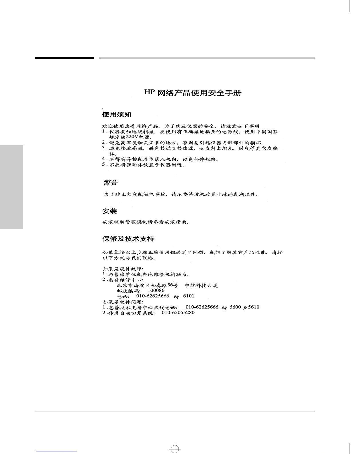
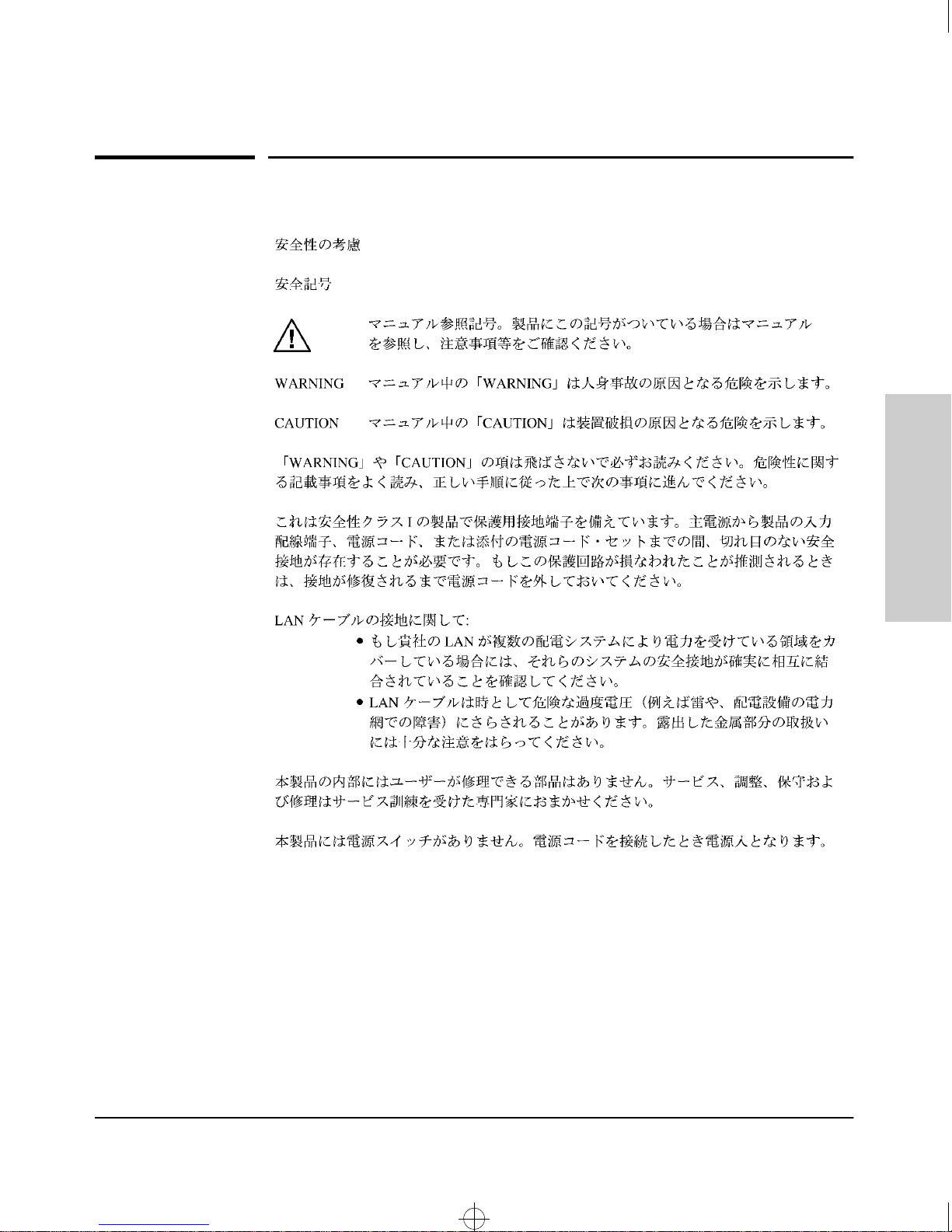
Safety Information (Chinese)
Safety Information (Chinese)
Statements
Safety and EMC Regulatory
C-6
Page 40
Roadhw0.bk : ROADHWC.FM Page 7 Thursday, May 28, 1998 5:40 PM
Safety and EMC Regulatory Statements
Safety Information (Japanese)
Safety Information (Japanese)
Safety and EMC Regulatory
Statements
C-7
Page 41

Roadhw0.bk : ROADHWC.FM Page 8 Thursday, May 28, 1998 5:40 PM
Safety and EMC Regulatory Statements
Regulatory Statements
Regulatory Statements
FCC Class A Statement (for U.S.A. Only)
This equipment has been tested and found to comply with the limits for a Class
A digital device, pursuant to Part 15 of the FCC Rules. These limits are
designed to provide reasonable protection against interference when the
equipment is operated in a commercial environment. This equipment generates, uses, and can radiate radio frequency energy and, if not installed and
used in accordance with the instruction manual, may cause interference to
radio communications. Operation of this equipment in a residential area may
cause interference in which case the user will be required to correct the
interference at his own expense.
Statements
Safety and EMC Regulatory
Canada
This product complies with Class A Canadian EMC requirements.
Australia/New Zealand
Complies with Australia/New Zealand
EMC Class A requirements.
Japan
VCCI Class A (For Japan Only)
C-8
Page 42
Roadhw0.bk : ROADHWC.FM Page 9 Thursday, May 28, 1998 5:40 PM
Safety and EMC Regulatory Statements
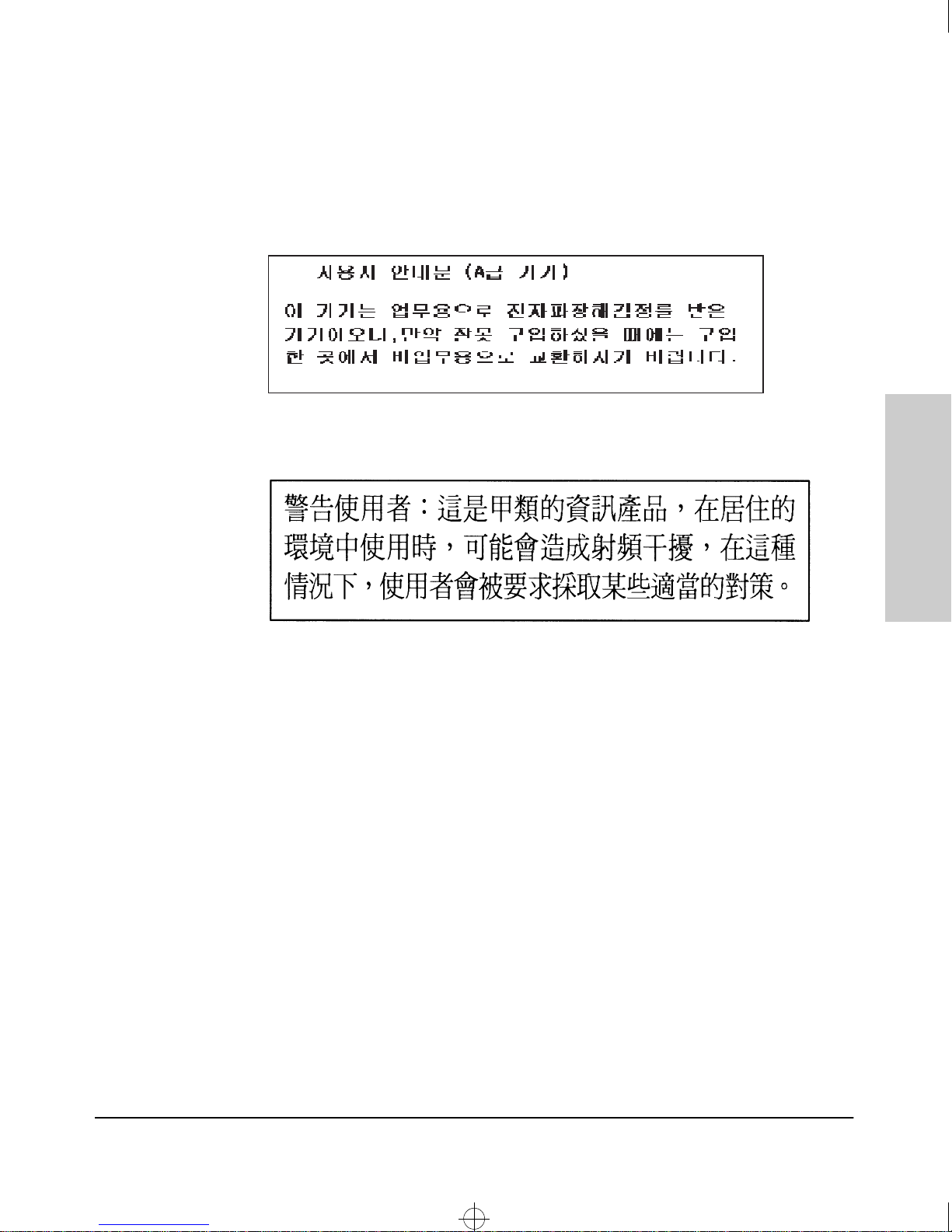
Korea
The top statement is for Class A products. The bottom statement is for Class
B products.
Regulatory Statements
Safety and EMC Regulatory
Taiwan
Statements
C-9
Page 43
Roadhw0.bk : ROADHWC.FM Page 10 Thursday, May 28, 1998 5:40 PM
Safety and EMC Regulatory Statements
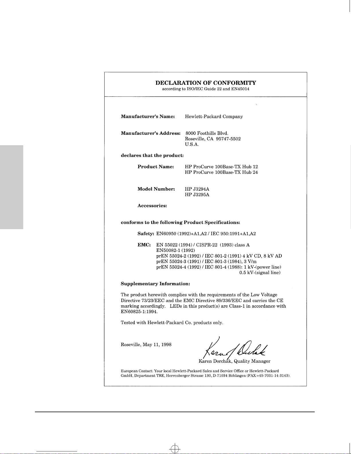
Regulatory Statements
European Community
Statements
Safety and EMC Regulatory
C-10
Page 44

Roadhw0IX.fm Page 1 Friday, July 17, 1998 7:29 PM
Index
Numerics
100Base-TX ports
cables used with … 2-4
10Base-T ports
cables used with … 2-4
LEDs for … 1-4
B
back of hub
description … 1-5
power connector … 1-5
C
cabinet
mounting the hub in … 2-6
cables
category 3, 4, 5 … B-1
crossover cable pinout … B-4
infrastructure requirements … 2-4
straight-through cable pinout … B-4
twisted-pair connector pin-outs … B-1
cabling infrastructure … 2-4
connector specifications … A-2
crossover cable
pin-out … B-4
D
description
back of hubs … 1-5
diagnostic tests … 3-4
testing the only … 3-4
testing twisted-pair cabling … 3-4
E
electrical specifications … A-1
environmental specifications … A-1
F
features
10/100 Hub 12, Hub 24 … 1-6
flashing LED
error indications … 3-3
front of hub
illustration … 1-2
H
horizontal surface
mounting hub on … 2-8
hub
description … 1-1
diagnostics with … 3-4
features … 1-6
mounting in a rack or cabinet … 2-6
mounting on a wall … 2-8
mounting on horizontal surface … 2-8
hub operation
verifying after installation … 2-5
I
illustration
front of hubs … 1-2
included parts … 2-1
installation
network cable requirements … 2-4
site preparation … 2-4
summary … 2-2
installing
10/100 hub 12/24 … 2-1
L
LEDs
10 Mbit/s ports … 1-4
descriptions of … 1-4
error indications … 3-3
Fault … 1-4
link ports … 1-4
Power … 1-4
Fault LED … 1-4, 2-5, 3-3
Index – 1
Page 45

Roadhw0IX.fm Page 2 Friday, July 17, 1998 7:29 PM
M
MDI-X to MDI network cable … B-2
MDI-X to MDI-X network cable … B-3
mounting the hub
in a rack … 2-6
on a horizontal surface … 2-8
on a wall … 2-8
N
network cables
100Base-TX connections … 2-4
10Base-T connections … 2-4
required types … 2-4
network ports
LEDs for … 1-4
types of … 1-3
P
physical specifications of hubs … A-1
ports
LEDs for … 1-4
types of … 1-3
power connector … 1-5
Power LED … 1-4, 2-5, 3-3
R
T
testing
twisted-pair cabling … 3-4
topologies
effects of improper topology … 3-2
samples of … 2-10
troubleshooting … 3-1
common network problems … 3-1
diagnostic tests … 3-4
effects of improper topology … 3-2
effects of non-standard cables … 3-2
testing the hub … 3-4
testing the twisted-pair cables … 3-4
twisted-pair cable
crossover cable pin-out … B-4
hub- to-hub or hub (MDI-X) connection … B-3
hub-to-computer connection … B-2
pin-outs … B-1, B-4
straight-through cable pin-out … B-4
testing … 3-4
twisted-pair port LEDs
100Mbps … 1-4
Link … 1-4
W
wall
mounting hub on … 2-8
rack
mounting the hub in … 2-6
resetting the hub
troubleshooting procedure … 3-4
S
sample topologies … 2-10
slow flash rate definition … 1-4
specifications … A-1
connectors … A-2
electrical … A-1
electromagnetic … A-2
environmental … A-1
physical … A-1
straight-through cable
pin-out … B-4
summary of hub installation … 2-2
2 – Index
Page 46

Printed in Singapore 7/98
Manual Part Number
5967-2280
*5967-2280*
Technical information in this document
is subject to change without notice.
© Copyright Hewlett-Packard Company
1998. All rights reserved. Reproduction,
adaptation, or translation without prior
written permission is prohibited except
as allowed under the copyright laws.
 Loading...