

HP Procurve Gigabit-SX, Procurve Gigabit-LX, Procurve 100-FX SC, Procurve 100/1000-T Installation Manual
Page 1

Artisan Technology Group is your source for quality
new and certied-used/pre-owned equipment
• FAST SHIPPING AND
DELIVERY
• TENS OF THOUSANDS OF
IN-STOCK ITEMS
• EQUIPMENT DEMOS
• HUNDREDS OF
MANUFACTURERS
SUPPORTED
• LEASING/MONTHLY
RENTALS
• ITAR CERTIFIED
SECURE ASSET SOLUTIONS
SERVICE CENTER REPAIRS
Experienced engineers and technicians on staff
at our full-service, in-house repair center
Instra
Remotely inspect equipment before purchasing with
our interactive website at www.instraview.com
Contact us: (888) 88-SOURCE | [email protected] | www.artisantg.com
SM
REMOTE INSPECTION
View
WE BUY USED EQUIPMENT
Sell your excess, underutilized, and idle used equipment
We also offer credit for buy-backs and trade-ins
www.artisantg.com/WeBuyEquipment
LOOKING FOR MORE INFORMATION?
Visit us on the web at www.artisantg.com for more
information on price quotations, drivers, technical
specications, manuals, and documentation
Page 2
xcvrs_3-2002.fm Page -1 Tuesday, April 2, 2002 3:23 PM
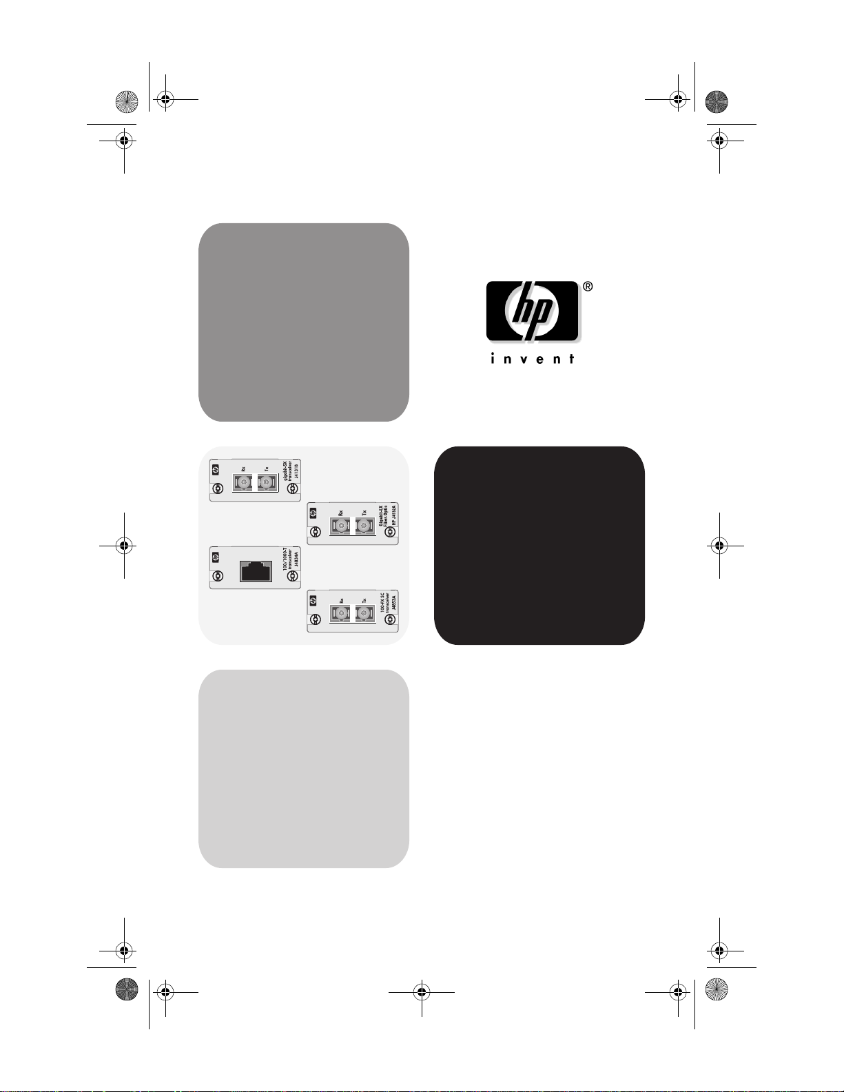
installation guide
www.hp.com/go/hpprocurve
hp procurve
high-speed transceivers
Artisan Technology Group - Quality Instrumentation ... Guaranteed | (888) 88-SOURCE | www.artisantg.com
Page 3

xcvrs_3-2002.fm Page 0 Tuesday, April 2, 2002 3:23 PM
Artisan Technology Group - Quality Instrumentation ... Guaranteed | (888) 88-SOURCE | www.artisantg.com
Page 4
xcvrs_3-2002.fm Page 1 Tuesday, April 2, 2002 3:23 PM
HP Procurve High-Speed Transceivers
Installation Guide
Introduction
The HP Procurve High-Speed Transceivers can be installed into a number
of HP Procurve networking devices to provide 100 Mbps and 1000 Mbps
connections to other compatible network devices.
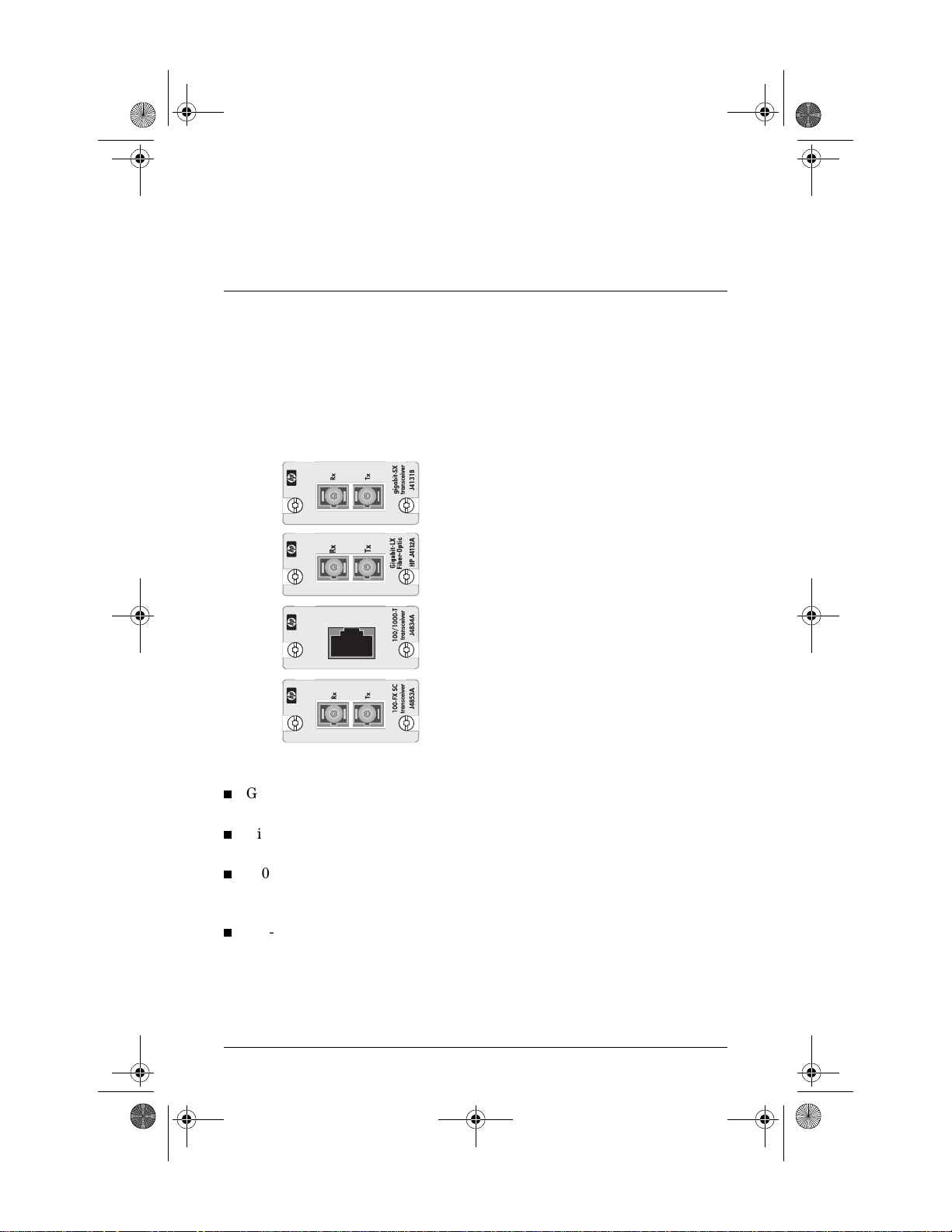
This document describes how to install, verify, and troubleshoot the
following HP Procurve High-Speed Transceivers:
HP Procurve Gigabit-SX Transceiver, J4131B
HP Procurve Gigabit-LX Transceiver, J4132A
HP Procurve 100/1000-T Transceiver, J4834A
HP Procurve 100-FX SC Transceiver, J4853A
Use these transceivers for the following network connectivity:
Gigabit-SX transceiver—1000 Mbps operation over multimode fiberoptic cable
Gigabit-LX transceiver—1000 Mbps operation over either singlemode or multimode fiber-optic cable
100/1000-T transceiver—1000 or 100 Mbps operation over Category
5 or better unshielded twisted-pair (UTP) or shielded twisted-pair
(STP) cables
100-FX SC transceiver—100 Mbps operation over multimode fiberoptic cable
For more information on the cables used with these transceivers and the
supported cable lengths, see page 5.
1
Artisan Technology Group - Quality Instrumentation ... Guaranteed | (888) 88-SOURCE | www.artisantg.com
Page 5

xcvrs_3-2002.fm Page 2 Tuesday, April 2, 2002 3:23 PM
Installation Notes
Please read these notes before proceeding.
The HP Procurve High-Speed Transceivers are supported in the
following HP Procurve networking devices:
• Series 2300 and 2500 Switches
• Series 4100GL Switches
For these switches, it is not necessary to turn off power to the
device before installing the transceiver into it:
• For the Series 2300 and 2500 switches, you can install the
transceivers while the switches are powered on, but you must
reset or reboot the switch after installing the transceiver to
initialize and activate it.
• For the Series 4100GL switches, the transceivers are installed in
the Gigabit Transceiver GL Module. In these switches, the transceivers are fully “hot swappable”—you can install or remove
them at any time without having to remove power from the
device or without having to first remove the module from the
switch, and without having to reset the switch. If you wish, you
can install the transceiver into the module first before installing
the module into the switch.
Please see the installation guide for the switch or module for more
information on installing the transceivers.
Note: As of the printing of this manual, the HP Procurve Switch
2424M
(J4093A) and its transceiver module, the HP Procurve
Switch 2424M Gigabit Stacking Module (J4130A) are obsolete.
As a result, the Gigabit-SX Transceiver, J4131B, has not been tested
in these devices and is therefore not supported. The other transceivers described in this manual were previously tested and are
supported in the Switch 2424M and its Gigabit Stacking Module.
For information on using transceivers in the HP Procurve Switch
2424M and the Gigabit Stacking Module, see their manuals on the
HP Procurve web site, http://www.hp.com/go/hpprocurve.
2
Artisan Technology Group - Quality Instrumentation ... Guaranteed | (888) 88-SOURCE | www.artisantg.com
Page 6
gg
xcvrs_3-2002.fm Page 3 Tuesday, April 2, 2002 3:23 PM
Installation Steps
To install the HP Procurve High-Speed Transceivers, follow these steps:
1. Fully insert the transceiver into an HP networking device's transceiver
slot until the transceiver “snaps” into place, and secure the transceiver
with the retaining screws.
If the transceiver slot is in a module that has not yet been installed into
the switch, then install the module into the switch.
2. For the Series 2300 and 2500 Switches, reset or reboot the switch.
3. Connect the network cable to the transceiver and check the transceiver
and network device for correct operation.
Details on these steps are provided in the rest of this document.
Insert the Transceiver Into the Slot
The transceivers are installed into an HP networking device, as follows:
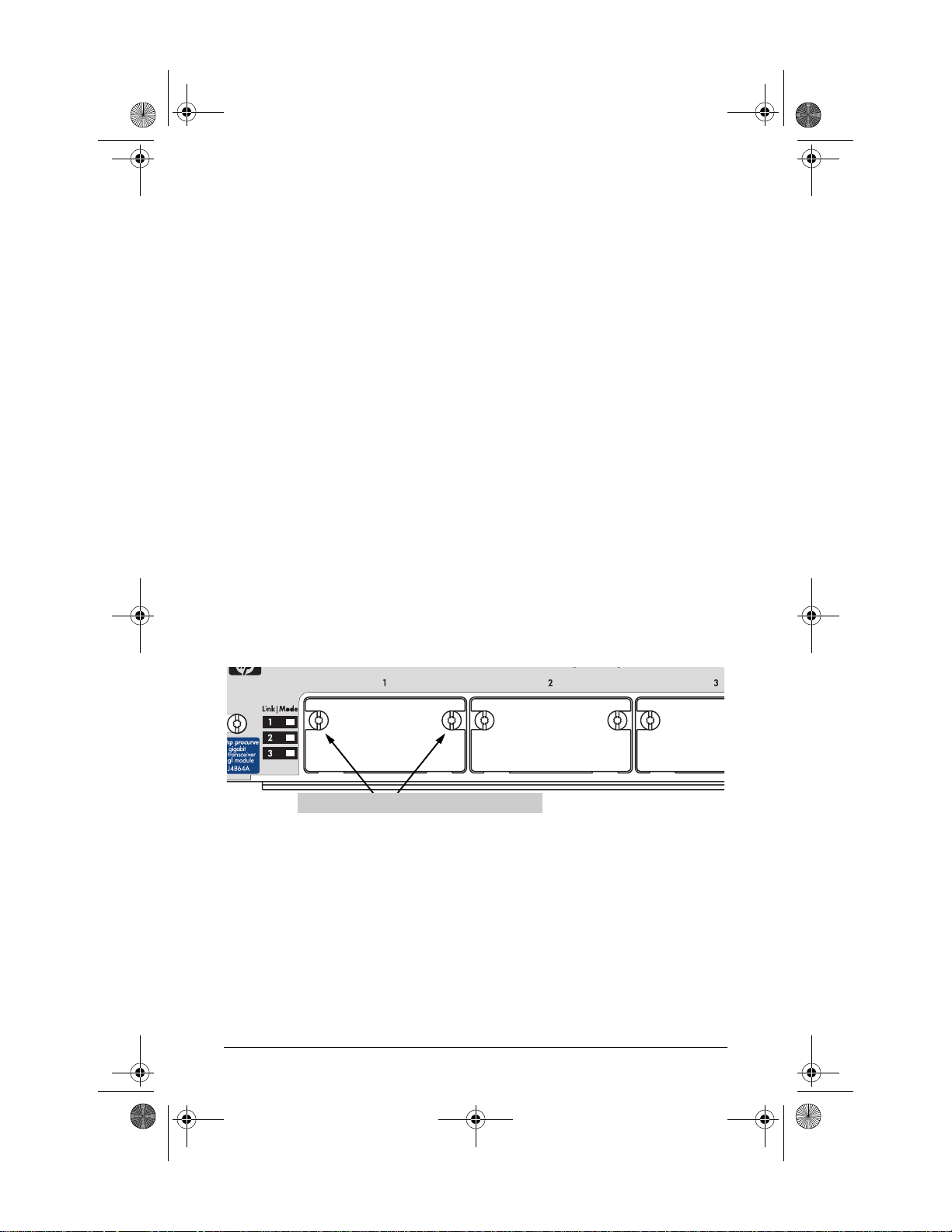
1. Using a flat-bladed or Torx T-10 screwdriver, unscrew the two retaining
screws on the slot cover plate or existing transceiver, and remove it
from the module or device. Retain the cover plate for possible future
use.
loosen these screws and remove the cover plate
2. Touch a grounded, metal object (such as a powered-on switch) to
discharge any static electricity on your body, then carefully remove the
transceiver from its protective anti-static packaging. Hold the transceiver by its bulkhead or edges, taking care not touch any of its board
components or metal connectors.
3
Artisan Technology Group - Quality Instrumentation ... Guaranteed | (888) 88-SOURCE | www.artisantg.com
Page 7
xcvrs_3-2002.fm Page 4 Tuesday, April 2, 2002 3:23 PM
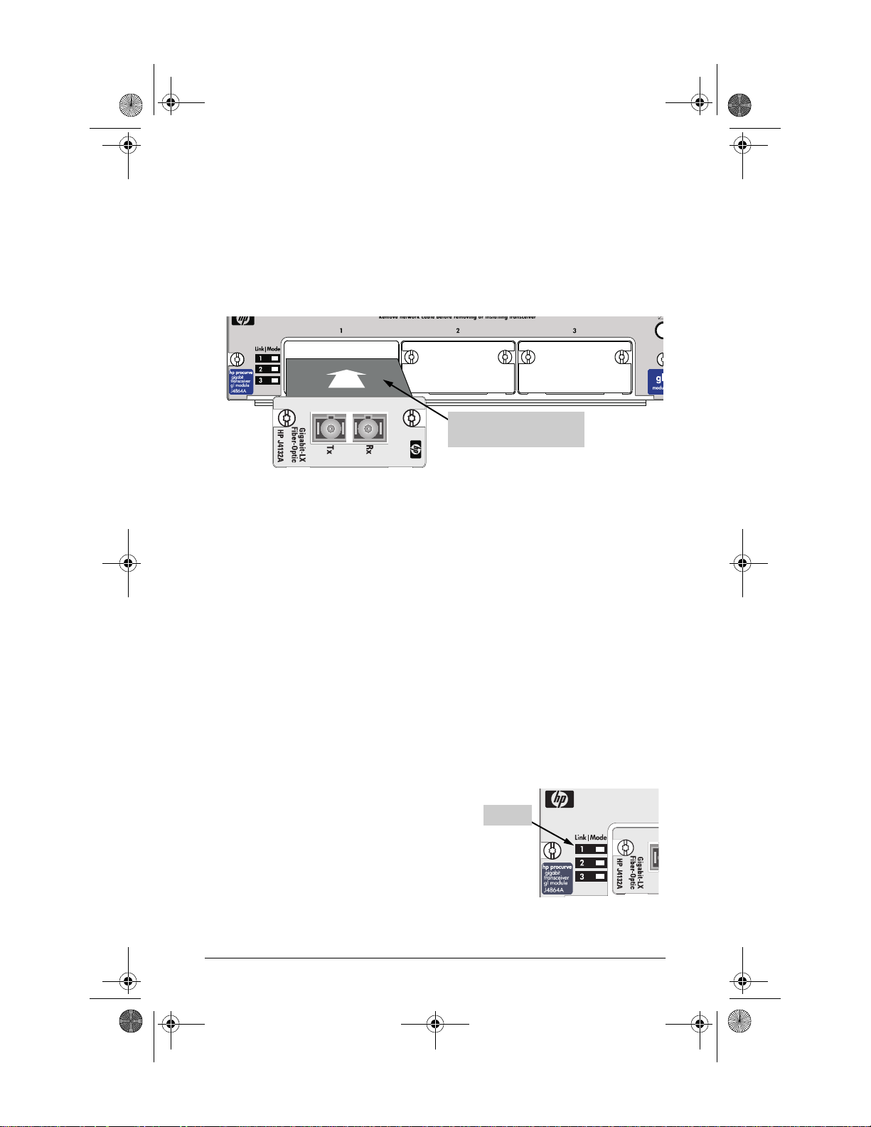
3. Slide the transceiver firmly into the transceiver slot as far as it will go.
The transceiver will “snap” into place, and the transceiver's faceplate
should touch the face of the switch or module. The following illustration
shows the transceiver being installed in an HP Procurve Switch Gigabit
Transceiver GL Module.
slide the transceiver i nto the
slot until it snaps into place
4. Using the flat-bladed or Torx T-10 screwdriver, tighten the retaining
screws on the transceiver until they are secure, but be careful that you
do not overtighten the screws.
5. If the transceiver is installed in a module and you have not yet installed
the module into the switch, reinstall the module into the switch and
make sure the switch is powered on, or if the transceiver is installed
directly into a switch, reset the switch, if necessary, to initialize the
transceivers. Please see the Installation Notes on page 2 for information
about initializing the transceivers in different HP Procurve networking
devices.
Connect Network Cables to the Transceiver Port
The network cables identified in the table on the next page should be used
with the HP Procurve High-Speed Transceivers.
When power is applied to this transceiver
and an active network cable is connected to
the transceiver port, the Link LED for the
port should be ON.
If the LED is off, see “Troubleshooting”, on
the page 11.
4
Artisan Technology Group - Quality Instrumentation ... Guaranteed | (888) 88-SOURCE | www.artisantg.com
Link LED
Page 8

xcvrs_3-2002.fm Page 5 Tuesday, April 2, 2002 3:23 PM
Port Type Cable Type Length Limits
Fiber-Optic Cables
Gigabit-SX 62.5/125 mm or 50/125 mm (core/
cladding) diameter, low metal
content, graded-index, multimode
fiber-optic cables that are fitted
with SC connectors. The cables
must comply with the ITU-T G.651
and ISO/IEC 793-2 Type A1b or A1a
standards.
Gigabit-LX 9/125 mm (core/cladding) diameter,
1310 nm, low metal content, single-
mode fiber-optic cables fitted with
SC connectors. The cables must
comply with the ITU-T G.652 and
ISO/IEC 793-2 Type B1 standards.
The multimode cables specified for
the Gigabit-SX Transceiver may
also be used, but a mode
conditioning patch cord may be
needed — see “Mode Conditioning
Patch Cord” on page 9 for more
information.
100-FX SC 62.5/125 mm or 50/125 mm (core/
cladding) diameter, low metal
content, graded-index, multimode
fiber-optic cables that are fitted
with SC connectors. The cables
must comply with the ITU-T G.651
and ISO/IEC 793-2 Type A1b or A1a
standards.
• 62.5 mm cable:
– 160 MHz*km = 220 meters
– 200 MHz*km = 275 meters
• 50 mm cable:
– 400 MHz*km = 500 meters
– 500 MHz*km = 550 meters
• single-mode cable: 10 kilometers
• multimode cable: 550 meters
• 2 kilometers for full-duplex
connections
• 412 meters for half-duplex
connections
Note: The Series 2300 and 2500
switches do not allow half-duplex
operation for the transceivers.
Twisted-Pair Cables
100/1000-T Category 5 or better, 100-ohm UTP
100 meters
or STP balanced cable. For 1000
Mbps (gigabit) operation, Category
5E cabling or better is
recommended.
Note: The HP Procurve 100/1000-T
Transceiver is compatible with the
IEEE 802.3ab standard including the
“Auto MDI/MDI-X” feature, which
Note: For 1000 Mbps operation, all
four wire pairs are used for data
transmissions. Please see the Note
on 1000Base-T Cable
Requirements on the next page.
allows you to use either straight-
through or crossover twisted-pair
cables for conne ction go any network
device including end nodes, such as
computers, or to other switches,
hubs, and routers.
5
Artisan Technology Group - Quality Instrumentation ... Guaranteed | (888) 88-SOURCE | www.artisantg.com
Page 9
xcvrs_3-2002.fm Page 6 Tuesday, April 2, 2002 3:23 PM
Note on 1000Base-T Cable Requirements. The Category 5 networking
cables that work for 100Base-TX connections should also work for
1000Base-T, as long as all four-pairs are connected. But, for the most robust
connections you should use cabling that complies with the Category 5E
specifications, as described in Addendum 5 to the TIA-568-A standard
(ANSI/TIA/EIA-568-A-5).
Because of the increased speed provided by 1000Base-T (Gigabit-T),
network cable quality is more important than for either 10Base-T or
100Base-TX. Site cabling that is being used to carry 1000Base-T networking
must comply with the IEEE 802.3ab standards. In particular, the cabling
must pass tests for Attenuation, Near-End Crosstalk (NEXT), and Far-End
Crosstalk (FEXT). Additionally, unlike the cables for 100Base-TX, the
1000Base-T cables must pass tests for Equal-Level Far-End Crosstalk
(ELFEXT), Multiple Disturber ELFEXT, and Return Loss.
When testing your cabling, be sure to include the patch cables that connect
the switch and other end devices to the patch panels on your site. The patch
cables are frequently overlooked when testing cable and they must also
comply with the cabling standards.
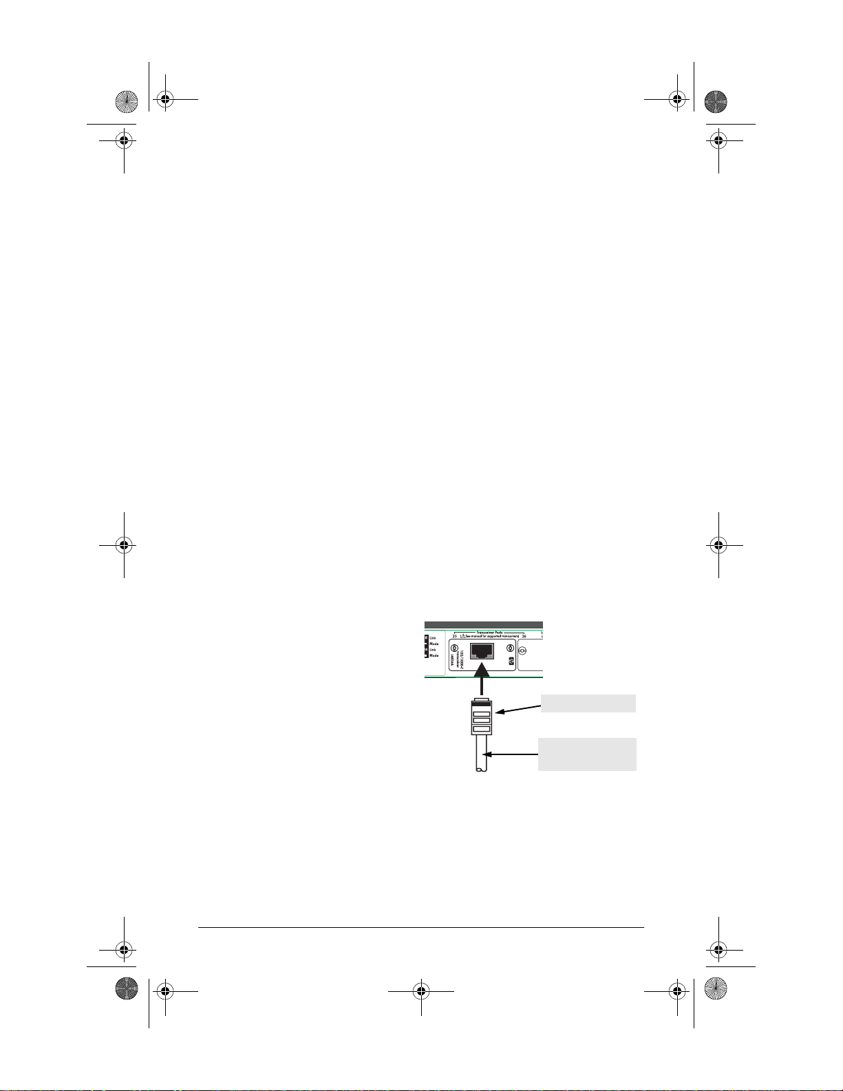
To connect a twisted-pair cable
to a transceiver:
Push the RJ-45 plug into the RJ-45
jack until the tab on the plug clicks
into place.
6
RJ-45 connector
Category 5 or better
UTP or STP cable:
Artisan Technology Group - Quality Instrumentation ... Guaranteed | (888) 88-SOURCE | www.artisantg.com
Page 10
xcvrs_3-2002.fm Page 7 Tuesday, April 2, 2002 3:23 PM
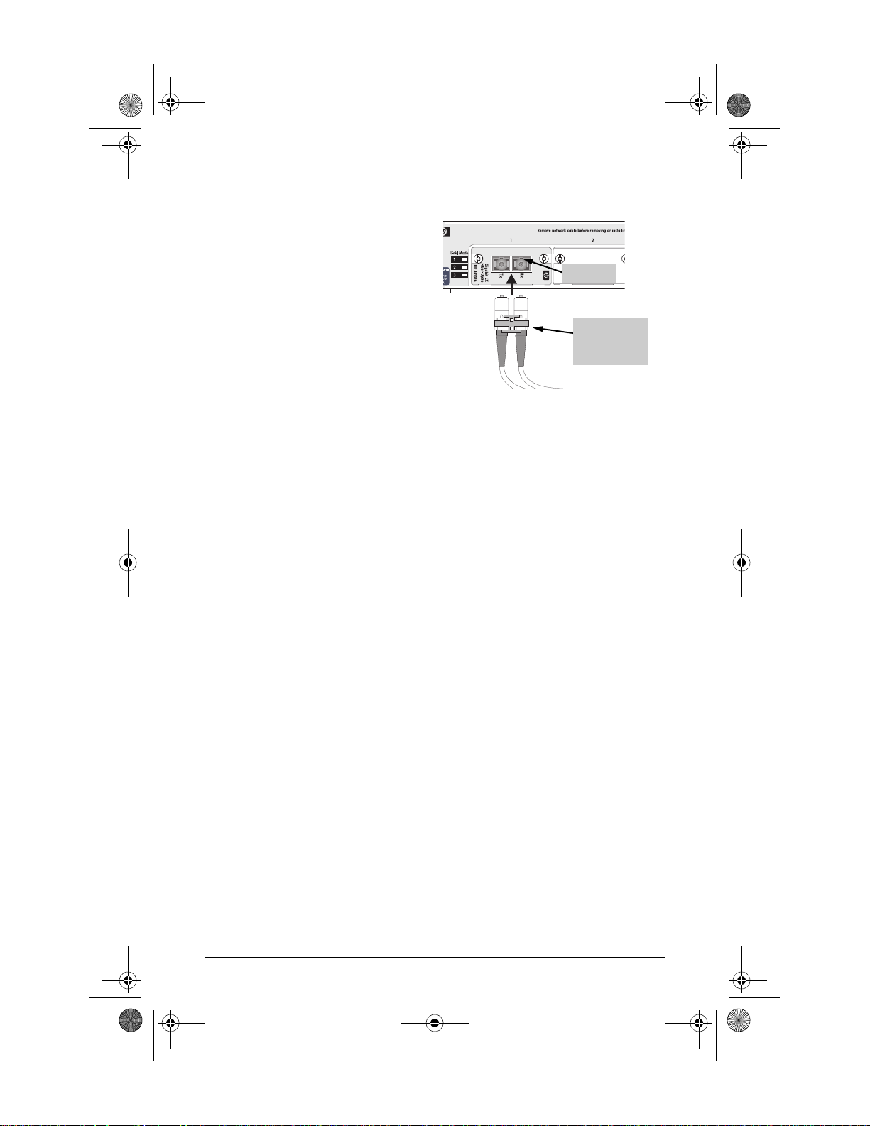
To connect a fiber-optic cable to
a transceiver:
1. For fiber-optic transceivers,
remove the plastic dust covers
notches
from the cable connectors and
from the transceiver port.
2. Press the connector into the jack
so that the tabs on the connector
Fiber cable
with duplex SC
connector
slide into the notches in the jack
and the connector snaps securely
into place.
3. If you are using cable with SC duplex connectors, as shown in the
illustration, both cables are connected simultaneously. If the cable has
simplex connectors, install them one at a time and make sure that the
cable connected into the Tx (transmit) port on the transceiver is
connected into the receive port on the device at the other end of the
cable; similarly, make sure the Rx (receive) port on the transceiver is
connected to the transmit port on the other device.
7
Artisan Technology Group - Quality Instrumentation ... Guaranteed | (888) 88-SOURCE | www.artisantg.com
Page 11
xcvrs_3-2002.fm Page 8 Tuesday, April 2, 2002 3:23 PM
Specifications for the HP Procurve High-Speed Transceivers
Laser
The Gigabit-SX and Gigabit-LX transceivers are Class 1 Laser Products
(Laser Klasse 1). They comply with IEC 825-2: 1993.
Environmental
Operating Non-Operating
Temperature: 0°C to 55°C (32°F to 131°F) -40°C to 70°C (-40°F to 158°F)
Relative humidity:
(non-condensing)
Maximum altitude: 4.6 km (15,000 ft) 4.6 km (15,000 ft)
15% to 95% at 40°C (104°F) 15% to 90% at 65°C (149°F)
Electromagnetic
Emissions
FCC part 15 Class A
EN55022 / CISPR-22 Class A
VCCI Class A
Complies with Canadian EMC Class A requirements
As described on page 2 of this document, these transceivers are designed
for operation with HP Procurve networking products with compatible
transceiver slots, and are listed in the Declaration of Conformity for those
products. See the Installation Guide for the network products for a copy
of the declaration and for other EMC statements.
Standards
The Gigabit-SX Transceiver is compatible with the IEEE 802.3z
Gigabit-SX standard. It transmits at 850 nm wavelength and accepts the
multimode fiber-optic cables for Gigabit-SX described on page 5.
The Gigabit-LX Transceiver is compatible with the IEEE 802.3z
Gigabit-LX standard. It transmits at 1300 nm wavelength and accepts the
single-mode or multimode fiber-optic cables for Gigabit-LX described on
page 5.
The 100/1000-T Transceiver is compatible with the IEEE 802.3ab
1000Base-T and IEEE 802.3u standards for 1000 Mbps and 100 Mbps
operation, respectively.
The 100-FX SC Transceiver is compatible with the IEEE 802.3u
100Base-FX standard. It transmits at 1300 nm wavelength and accepts
the multimode fiber-optic cables described on page 5.
8
Artisan Technology Group - Quality Instrumentation ... Guaranteed | (888) 88-SOURCE | www.artisantg.com
Page 12

xcvrs_3-2002.fm Page 9 Tuesday, April 2, 2002 3:23 PM
Mode Conditioning Patch Cord for Gigabit-LX
The following information applies to installations in which multimode
fiber-optic cables are connected to a Gigabit-LX Transceiver.
Unlike Gigabit-SX, which connects to only multimode fiber-optic cabling,
Gigabit-LX can use either single-mode or multimode cable. Multimode cable
has a design characteristic called “Differential Mode Delay”, which requires
that the transmission signals be “conditioned” to compensate for the cable
design and thus prevent resulting transmission errors. Since Gigabit-SX is
designed to operate only with multimode cable, Gigabit-SX transceivers can
provide that transmission conditioning internally.
Gigabit-LX transceivers, since they are designed to operate with both singlemode and multimode cable, do not provide the transmission conditioning
internally. Thus, under certain circumstances, depending on the cable used
and the lengths of the cable runs, an external Mode Conditioning Patch
Cord may need to be installed between the Gigabit-LX transmitting device
and the multimode network cable to provide the transmission conditioning.
If you experience a high number of transmission errors on the Gigabit-LX
ports, usually CRC or FCS errors, you may need to install one of these patch
cords between the Gigabit-LX port in your switch and your multimode fiberoptic network cabling, and between the Gigabit-LX transmission device
and the network cabling at the other end of the multimode fiber-optic cable
run. A patch cord must be installed at both ends.
The patch cord consists of a short length of single-mode fiber cable coupled
to graded-index multimode fiber cable on the transmit side, and only
multimode cable on the receive side. The section of single-mode fiber is
connected in such a way that it minimizes the effects of the differential mode
delay in the multimode cable.
Note
Most of the time, if you are using good quality graded-index multimode fiber
cable that adheres to the standards listed on page 5, there should not be a
need to use mode conditioning patch cords in your network. This is especially true if the fiber runs in your network are relatively short.
If you are using single-mode fiber-optic cabling in your network, there is no
need to use mode conditioning patch cords. Connect the single-mode
network cable directly to the Gigabit-LX transceiver.
9
Artisan Technology Group - Quality Instrumentation ... Guaranteed | (888) 88-SOURCE | www.artisantg.com
Page 13
xcvrs_3-2002.fm Page 10 Tuesday, April 2, 2002 3:23 PM
Installing the Patch Cord
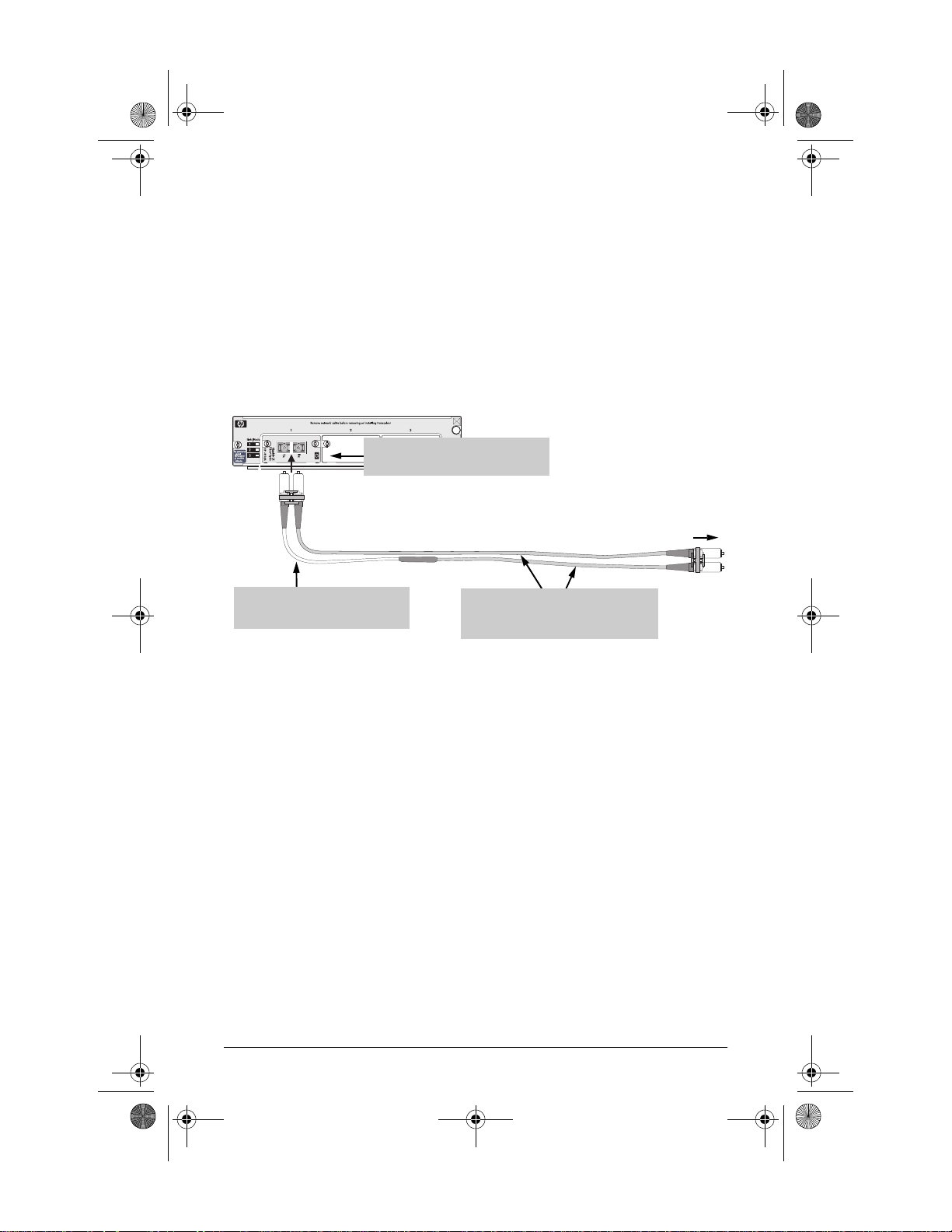
As shown in the illustration below, connect the patch cord to the
Gigabit-LX Transceiver with the section of single-mode fiber plugged in to
the Tx (transmit) port. Then, connect the other end of the patch cord to your
network cabling patch panel, or directly to the network multimode fiber.
If you connect the patch cord directly to the network cabling, you may need
to install a female-to-female adapter to allow the cables to be connected
together.
Gigabit-LX Transceiver in
Gigabit Transceiver GL Module
to network
Mode Conditioning
Patch Cord
multimode
cabling
single-mode section plugs into Tx
port on Gigabit-LX Transceiver
the multimode cable in the patch cord
must match the chara cteristics of your
network cable
Make sure you purchase a patch cord that has SC connectors on the end
that connects to the Gigabit-LX Transceiver and has multimode fibers that
match the characteristics of the multimode fiber in your network.
Recommended Patch Cords
Hewlett-Packard maintains a list of recommended Mode Conditioning
Patch Cords that have been tested and verified to operate correctly with the
HP Procurve Gigabit-LX Transceiver.
The list is on the HP Procurve web site, http://www.hp.com/go/hpprocurve,
in the Technical Support section.
10
Artisan Technology Group - Quality Instrumentation ... Guaranteed | (888) 88-SOURCE | www.artisantg.com
Page 14

xcvrs_3-2002.fm Page 11 Tuesday, April 2, 2002 3:23 PM
Troubleshooting
The following problems may exist:
The Link LED for the transceiver is not on, even though the transceiver
is receiving power and the network cable is connected. Check the
following:
• Verify that the networked device at the other end of the cable is powered
on and operating correctly.
• Verify that the cables are connected correctly to the transceiver ports. See
step 3 in the installation instructions.
• Verify that the cable length does not exceed the maximum distances listed
on page 5 and that the cables comply with the specifications on that page.
• Check all cabling and connections (including patch panels) to make sure
that all connections are secure, no connectors are damaged, and that none
of the connectors have a dust buildup or other object in the way that may
cause interference to the light transmission or electrical connections. If all
connections are OK, try a different cable.
• Verify that the networked device connected to the transceiver is the correct
type for the transceiver used.
• Verify that the transceiver is supported by the switch or module into which
you are installing it. See the information on page 2 to identify which
transceivers are supported by which network devices.
• If the transceiver is installed in a Series 2300 or Series 2500 Switch, try
resetting or cycling power (turn the power off and then back on) on the
switch. Resetting the switch causes a complete self test to be performed,
which also tests the transceivers. If the transceiver is installed in a Series
4100GL switch, try removing and reinstalling the module in which the
transceiver is installed. This will invoke the most complete self test of the
transceiver, without needing to power cycle the switch.
• Verify that the transceiver port has not been disabled through a switch
configuration change. You can use the console interface, or, if you have
configured an IP address on the switch, use the web browser interface, or
HP TopTools for Hubs & Switches network management software to
determine the state of the port and re-enable the port if necessary.
• Verify that the switch port configuration matches the configuration of
the attached device. For example, if the switch port is configured as
“Auto”, the port on the attached device also MUST be configured as
“Auto”. Depending on the port type, twisted-pair or fiber-optic, if the
configurations don’t match, the results could be a very unreliable
connection, or no link at all.
11
Artisan Technology Group - Quality Instrumentation ... Guaranteed | (888) 88-SOURCE | www.artisantg.com
Page 15

xcvrs_3-2002.fm Page 12 Tuesday, April 2, 2002 3:23 PM
The switch Link LED for the transceiver port is blinking. This
condition occurs on the Series 2300 and 2500 switches. After installing the
transceiver, these switches must be reset or rebooted to initialize the
transceiver. The flashin g LED tells you that th e transceiver is not oper ational
until the switch is reset or rebooted.
The switch Fault LED and Link LED for the transceiver port are
blinking. The transceiver may not be installed correctly, or may be faulty.
Disconnect power from the networking device and reinstall the transceiver
into the module or networking device. Verify the transceiver screws are
tightened. Turn the device power back on, and if the flashing persists, the
transceiver may be faulty.
For additional troubleshooting, you can also use the device's console interface, the
switch’s web browser interface, or HP Top Tools for Hubs & Switches to troubleshoot and configure the High-Speed Transceiver port. See the switch's Management
and Configuration Guide for more information. If you are still having trouble, see
the “Customer Support Services” below.
Customer Support Services
If you are having any trouble with your transceiver, Hewlett-Packard offers
support 24 hours a day, seven days a week through the use of a number of
automated electronic services. See the Customer Support/Warranty booklet
that came with your transceiver for information on how to use these services
to get technical support. The HP networking products World Wide Web site,
http://www.hp.com/go/hpprocurve also provides up-to-date support information and contact phone numbers. Click on the
that web page.
Additionally, your HP-authorized network reseller can also provide you with
assistance, both with services that they offer and with services offered by
HP.
button on
12
Artisan Technology Group - Quality Instrumentation ... Guaranteed | (888) 88-SOURCE | www.artisantg.com
Page 16

xcvrs_3-2002.fm Page 13 Tuesday, April 2, 2002 3:23 PM
Artisan Technology Group - Quality Instrumentation ... Guaranteed | (888) 88-SOURCE | www.artisantg.com
Page 17
xcvrs_3-2002.fm Page 14 Tuesday, April 2, 2002 3:23 PM
Technical information in this document is
subject to change without notice.
ãCopyright Hewlett-Packard Company, 2000,
2002. All rights reserved. Reproduction,
adaptation, or translation without prior written
permission is prohibited except as allowed
under the copyright laws.
Product of Singapore, 04/2002
Manual Part Number
5990-3012
*5990-3012*
Artisan Technology Group - Quality Instrumentation ... Guaranteed | (888) 88-SOURCE | www.artisantg.com
Page 18

Artisan Technology Group is your source for quality
new and certied-used/pre-owned equipment
• FAST SHIPPING AND
DELIVERY
• TENS OF THOUSANDS OF
IN-STOCK ITEMS
• EQUIPMENT DEMOS
• HUNDREDS OF
MANUFACTURERS
SUPPORTED
• LEASING/MONTHLY
RENTALS
• ITAR CERTIFIED
SECURE ASSET SOLUTIONS
SERVICE CENTER REPAIRS
Experienced engineers and technicians on staff
at our full-service, in-house repair center
Instra
Remotely inspect equipment before purchasing with
our interactive website at www.instraview.com
Contact us: (888) 88-SOURCE | [email protected] | www.artisantg.com
SM
REMOTE INSPECTION
View
WE BUY USED EQUIPMENT
Sell your excess, underutilized, and idle used equipment
We also offer credit for buy-backs and trade-ins
www.artisantg.com/WeBuyEquipment
LOOKING FOR MORE INFORMATION?
Visit us on the web at www.artisantg.com for more
information on price quotations, drivers, technical
specications, manuals, and documentation
 Loading...