

Page 1

HP Pro 8 Tablet with Voice
Maintenance and Service Guide
IMPORTANT! This document is intended for HP
authorized service providers only.
Page 2

© Copyright 2017 HP Development Company,
L.P.
© 2017 Google Inc. All rights reserved. Android
and Google are registered trademarks of
Google Inc. Bluetooth is a trademark owned by
its proprietor and used by HP Inc. under license.
SD Logo is a trademark of its proprietor.
The information contained herein is subject to
change without notice. The only warranties for
HP products and services are set forth in
the express warranty statements
accompanying such products and services.
Nothing herein should be construed as
constituting an additional warranty. HP shall
not be liable for technical or editorial errors or
omissions contained herein.
First Edition: April 2017
Document Part Number: 918956-001
Product notice
This guide describes features that are common
to most models. Some features may not be
available on your tablet.
Software terms
By installing, copying, downloading, or
otherwise using any software product
preinstalled on this tablet, you agree to be
bound by the terms of the HP End User License
Agreement (EULA). If you do not accept these
license terms, your sole remedy is to return the
entire unused product (hardware and software)
within 14 days for a refund subject to the
refund policy of your place of purchase.
For any further information or to request a full
refund of the tablet, please contact your local
point of sale (the seller).
Page 3

Table of contents
1 Product description ....................................................................................................................................... 1
2 External component identication .................................................................................................................. 3
Identifying components ......................................................................................................................................... 3
Front .................................................................................................................................................... 3
Back ..................................................................................................................................................... 5
Locating product information ................................................................................................................................ 6
Locating system information ................................................................................................................................ 6
3 Illustrated parts catalog ................................................................................................................................ 7
Tablet major components ...................................................................................................................................... 7
Miscellaneous parts ............................................................................................................................................... 9
4 Removal and replacement preliminary requirements ..................................................................................... 10
Tools required ...................................................................................................................................................... 10
Service considerations ......................................................................................................................................... 10
Plastic parts ....................................................................................................................................... 10
Cables and connectors ...................................................................................................................... 10
Grounding guidelines ........................................................................................................................................... 10
Electrostatic discharge damage ........................................................................................................ 10
Packaging and transporting guidelines .......................................................................... 12
Workstation guidelines ................................................................................ 12
5 Removal and replacement procedures ........................................................................................................... 14
Tablet component replacement procedures ....................................................................................................... 14
Card tray ............................................................................................................................................................... 14
Back cover ............................................................................................................................................................ 15
Battery ................................................................................................................................................................. 16
Middle frame cover .............................................................................................................................................. 17
Rear-facing webcam ............................................................................................................................................ 18
Antenna board ..................................................................................................................................................... 20
Speaker ................................................................................................................................................................ 21
Volume and power button board ......................................................................................................................... 23
System board ....................................................................................................................................................... 24
Front-facing webcam ........................................................................................................................................... 26
Touchscreen display panel assembly .................................................................................................................. 27
iii
Page 4

6 Specications .............................................................................................................................................. 28
7 Backing up and recovering your data ............................................................................................................. 29
Automatically updating apps .............................................................................................................................. 29
Manually updating apps, widgets, and the operating system ............................................................................ 29
Back up and reset ................................................................................................................................................ 29
Factory data reset ................................................................................................................................................ 30
Resetting with your tablet turned on ............................................................................................... 30
Resetting with your tablet without the operating system ............................................................... 30
Updating your tablet using an over-the-air (OTA) update .................................................................................. 31
Updating your tablet using a le-based update ................................................................................................. 32
8 Power adapter requirements ........................................................................................................................ 33
Requirements for all countries ............................................................................................................................ 33
Requirements for specic countries and regions ................................................................................................ 33
9 Recycling .................................................................................................................................................... 35
Index ............................................................................................................................................................. 36
iv
Page 5

1 Product description
Category Description
Product Name HP Pro 8 Tablet with Voice
Processor MediaTek MT8735V/W
Panel
8 inch (21.07 cm), 800x1280, 16:10 aspect ratio, brightness: typical 500 nits (cd/m2)
10-nger capacitive multi-touch
Memory 2 GB LPDDR3, integrated onto system board
Storage 16 GB eMMC
Audio and video Support voice call via single 1.2 W internal speaker, wired or Bluetooth® headset, speaker and
receiver mode
Front-facing camera: 2 MP xed focus
Back camera: 5 MP auto focus with ash LED
One external microphone from audio-out (headphone)/audio-in (microphone) combo jack
Sensors Accelerometer
Ambient light sensor (ALS)
Proximity Sensor
Gyroscope
Wireless networking WPAN Bluetooth:
Bluetooth 4.0 LE
WLAN:
802.11 b/g/n, 2.4 GHz
Support for Miracast
GPS:
GPS, A-GPS, GLONASS, Geo Tagging
WWAN:
GSM 850/900/1800/1900, WCDMA B1 and B8, LTE (Band 3 and 40)
Single SIM card
External expansion
●
MicroSD card slot expandable up to 64 GB, supports SD and SDHC
●
On-The-Go (OTG) 2.0 extension cable to connect to USB devices. In addition to data transfer
it can connect to peripherals such as a mouse or keyboard, and connect to a USB stick or
external drive.
●
USB to microUSB extension cable to connect to USB devices.
Ports
●
Audio: 3.5 mm audio-out (headphone)/audio-in (microphone) combo jack for headset
●
Micro Type-B USB connector
●
Micro SIM card + microSD card slot supporting a single card tray
1
Page 6

Category Description
●
1 barrel charger
●
POGO pin connector
Power requirements Battery:
Non-removable, 6000 mAh, 3.8 V Lithium-Ion Polymer battery
Adapter:
Barrel type charger
Operating system Preinstalled:
Android v6.0
Supports OTA update of Android v7.0.
Software Supports OTA updates for 3 years after purchase.
Serviceability End user replaceable parts:
●
AC adapter
2 Chapter 1 Product description
Page 7
2 External component identication
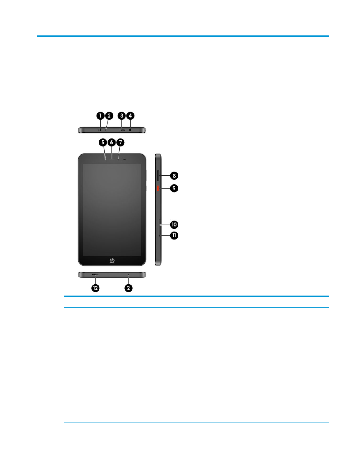
Identifying components
Front
Component Description
(1) Power connector Connects an AC adapter.
(2) Microphones Receive sound.
(3) Micro-B USB port Provides data transfer.
NOTE: A micro-B USB extension cable is included with your
voice tablet for connecting to USB devices.
(4) Audio-out (headphone)/Audio-in (microphone)
combo jack
Connects optional powered stereo speakers, headphones,
earbuds, a headset, or a television audio cable. Also connects an
optional headset microphone. This jack does not support
optional standalone microphones.
WARNING! To reduce the risk of personal injury, lower the
volume setting before putting on headphones, earbuds, or a
headset.
NOTE: When a device is connected to the jack, the speakers are
disabled.
Identifying components 3
Page 8

Component Description
(5) Battery light When AC power is connected:
●
White: The battery charge is greater than 99 percent.
●
Amber: The battery charge is from 0 to 99 percent.
●
O: The battery is not charging.
When AC power is disconnected (battery not charging):
●
Blinking amber: The battery has reached a low battery
level. When the battery has reached a critical battery level,
the battery light begins blinking rapidly.
●
O: The battery is not charging.
(6) Earpiece Produces sound for phone calls.
(7) Camera Records video and captures photographs.
(8) Volume button Press to increase or decrease sound.
(9) Power button
●
When the voice tablet is o, press and hold the button for
about 2 seconds to turn on the voice tablet.
●
When the voice tablet is on, press the button briey to
initiate Sleep.
●
When the voice tablet is in the Sleep state, press the
button briey to exit Sleep.
CAUTION: Pressing and holding down the power button
without waiting for the Power o message can result in the loss
of unsaved information.
(10) Micro SIM card/MicroSD memory card tray Supports a micro subscriber identity module (SIM) card and a
microSD memory card in a dual-compartment tray.
NOTE: Your device has read/write support for microSD
memory cards up to 64 GB.
(11) Card tray access hole Insert a small straightened paper clip into the hole to release the
tray.
(12) Speaker Produces sound.
4 Chapter 2 External component identication
Page 9
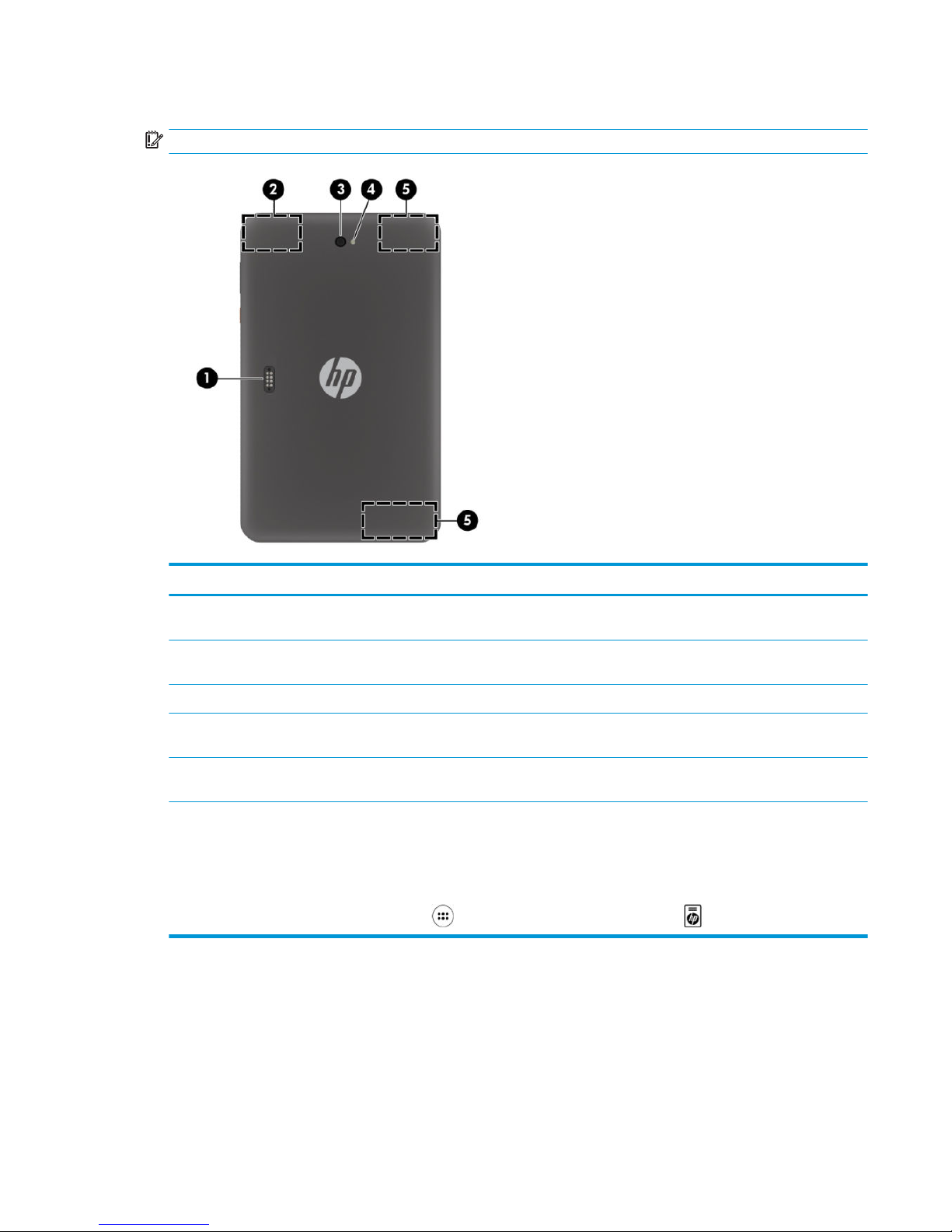
Back
IMPORTANT: Only HP service providers are authorized to open the back cover.
Component Description
(1) Accessory connector Allows you to connect accessories (purchased separately) that
support POGO pin connectors.
(2) WLAN antenna* Sends and receives wireless signals to communicate with
wireless local area networks (WLANs).
(3) Camera Records video and captures photographs.
(4) Camera ash Provides a camera ash. You can control the ash using camera
apps.
(5) WWAN antennas* Send and receive wireless signals to communicate with wireless
wide area networks (WWANs).
*The antennas are not visible from the outside of the voice tablet. For optimal transmission, keep the areas immediately around the
antennas free from obstructions.
For wireless regulatory notices, see the section of the Product Notices that applies to your country or region.
To access this guide:
▲
On the Home screen, touch the All Apps icon , and then touch the HP Documentation app . Select the document.
Identifying components 5
Page 10
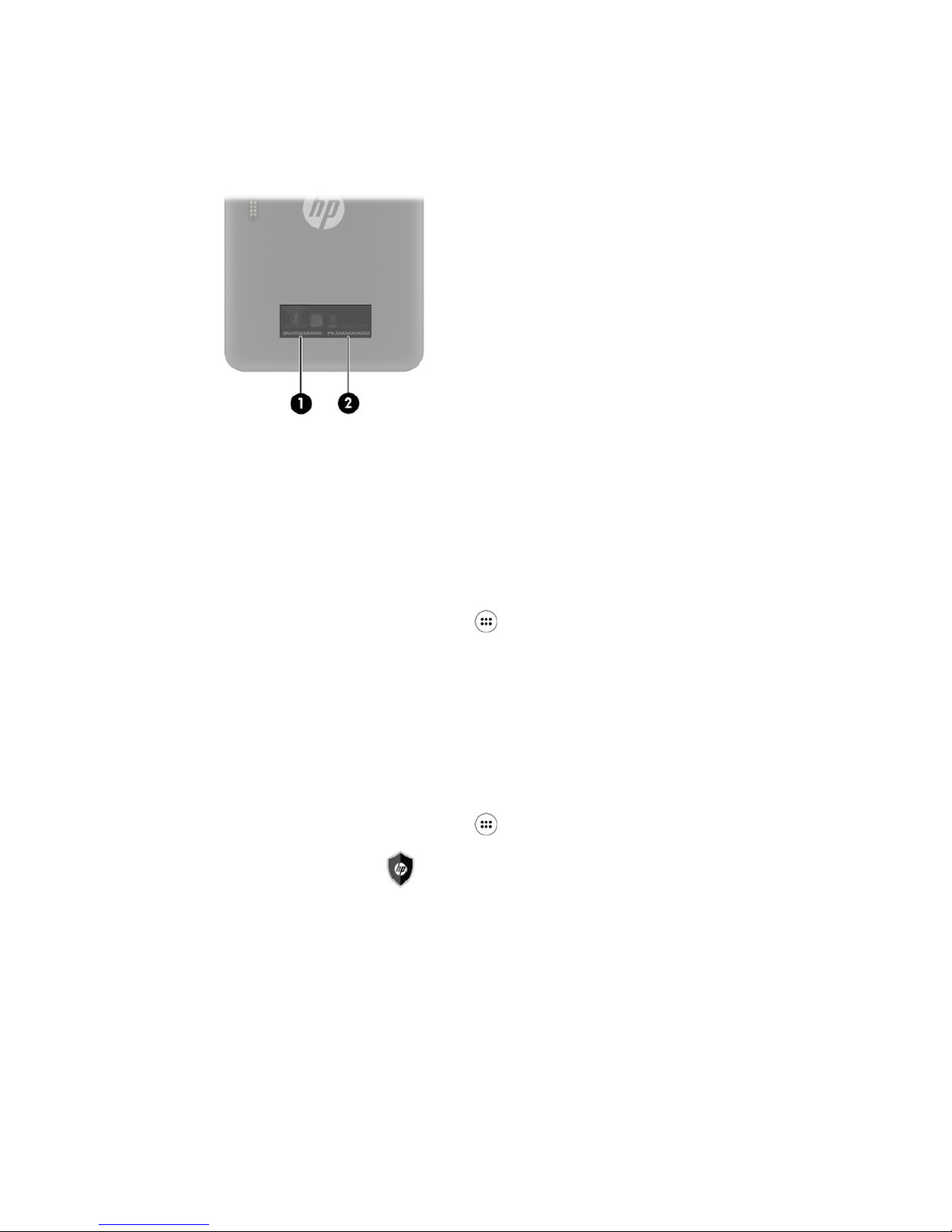
Locating product information
The serial number (1) and product number (2) of your tablet are located on the back cover of the tablet. You
may need the information when you travel internationally or when you contact support.
Locating system information
System information is also available from two apps: Settings and HP Device Hub.
The About tablet option of the Settings app provides information about the serial number, product number,
and IMEI.
To access the About tablet setting:
1.
On the Home screen, touch the All Apps icon .
2. Touch Settings, and then touch About tablet.
View the model number and version information.
3. To view IMEI and serial number information, touch Status.
The HP Device Hub app also provides access to system information, warranty information, support, operating
system updates.
To access the HP Device Hub app:
1.
On the Home screen, touch the All Apps icon .
2.
Touch the HP Device Hub icon .
6 Chapter 2 External component identication
Page 11

3 Illustrated parts catalog
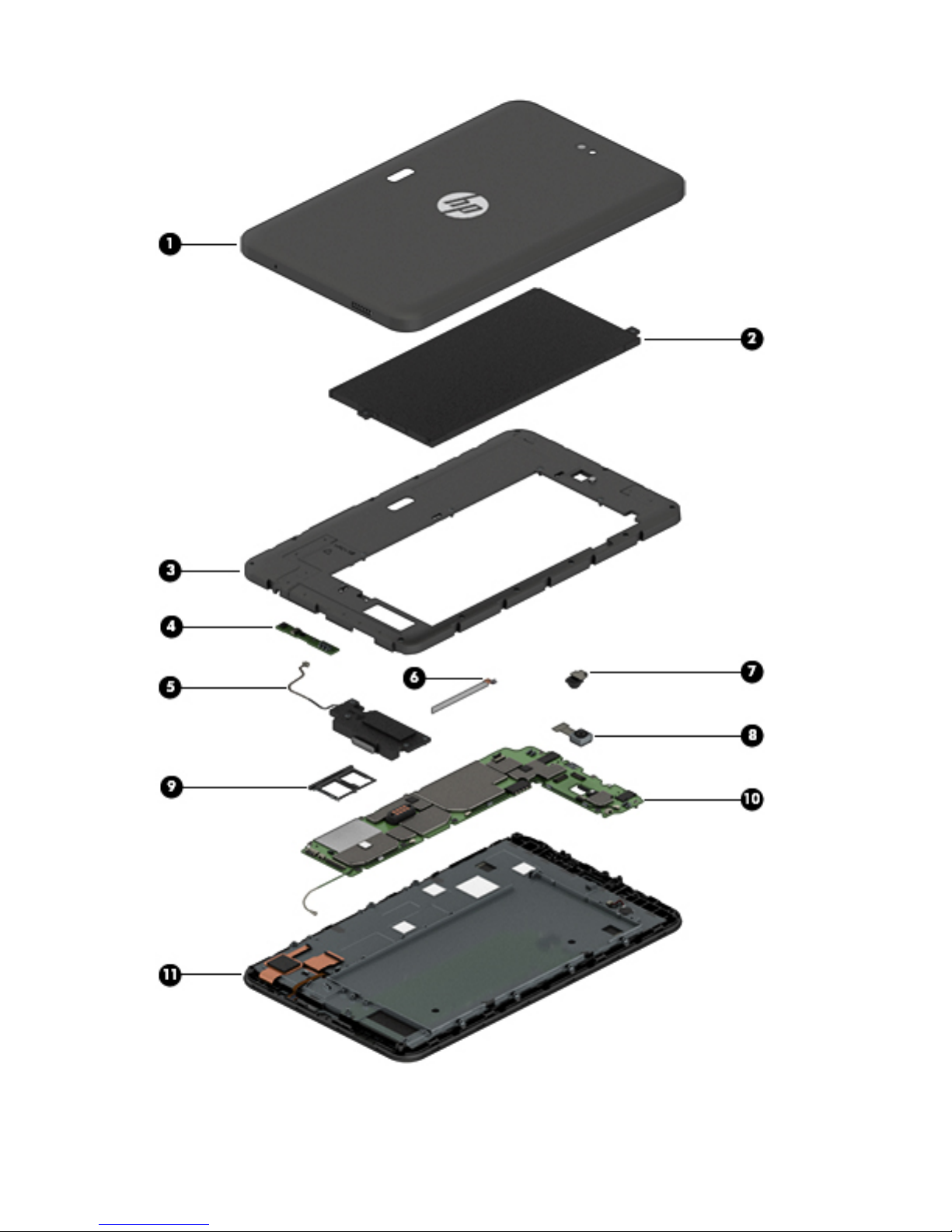
Tablet major components
NOTE: HP continually improves and changes product parts. For complete and current information on
supported parts for your tablet, go to http://partsurfer.hp.com, select your country or region, and then follow
the on-screen instructions.
Tablet major components 7
Page 12
8 Chapter 3 Illustrated parts catalog
Page 13

Item Component Spare part number
(1) Back cover (includes camera lens) 926157-001
Back cover with logo (includes camera lens) 937866-001
(2) Battery, 6000 mAh, 3.8 V Lithium-Ion Polymer 928848-001
(3) Middle frame cover(includes graphite heat sink, camera light guide, Wi-Fi antennas, GPS,
Bluetooth, and ngerprint reader sensor)
926158-001
(4) Antenna board 926160-001
(5) Speaker kit (includes speaker and cables) 926164-001
(6) Volume and power button board 926161-001
(7) Front-facing webcam (includes cable) 926165-001
(8) Rear-facing webcam (includes cable) 926166-001
(9) Micro SIM/microSD card tray 926162-001
(10) System board (includes motor, coaxial line, and ngerprint reader strobe light) 926568-001
(11) Touchscreen display panel assembly 926159-001
Miscellaneous parts
Component Spare part number
AC adapter 100-240 V input, 9 V/3 A output 922504-001
AC adapter 100-240 V input, 5 V/3 A output 928873-001
Cable micro-B USB to USB 931553-001
Cable micro-OTG 931553-001
Screw kit 926163-001
Miscellaneous parts 9
Page 14
4 Removal and replacement preliminary
requirements
Tools required
You will need the following tools to complete the removal and replacement procedures:
●
Magnetic Phillips 000 and 00 screwdrivers
●
Plastic pry tool
Service considerations
The following sections include some of the considerations that you must keep in mind during disassembly
and assembly procedures.
NOTE: As you remove each subassembly from the tablet, place the subassembly (and all accompanying
screws) away from the work area to prevent damage.
Plastic parts
CAUTION: Using excessive force during disassembly and reassembly can damage plastic parts. Use care
when handling the plastic parts. Apply pressure only at the points designated in the maintenance
instructions.
Cables and connectors
CAUTION: When servicing the tablet, be sure that cables are placed in their proper locations during the
reassembly process. Improper cable placement can damage the tablet.
Cables must be handled with extreme care to avoid damage. Apply only the tension required to unseat or seat
the cables during removal and insertion. Handle cables by the connector whenever possible. In all cases, avoid
bending, twisting, or tearing cables. Be sure that cables are routed in such a way that they cannot be caught
or snagged by parts being removed or replaced. Handle ex cables with extreme care; these cables tear
easily.
Grounding guidelines
Electrostatic discharge damage
Electronic components are sensitive to electrostatic discharge (ESD). Circuitry design and structure determine
the degree of sensitivity. Networks built into many integrated circuits provide some protection, but in many
cases, ESD contains enough power to alter device parameters or melt silicon junctions.
A discharge of static electricity from a nger or other conductor can destroy static-sensitive devices or
microcircuitry. Even if the spark is neither felt nor heard, damage may have occurred.
10 Chapter 4 Removal and replacement preliminary requirements
Page 15

An electronic device exposed to ESD may not be aected at all and can work perfectly throughout a normal
cycle. Or the device may function normally for a while, then degrade in the internal layers, reducing its life
expectancy.
CAUTION: To prevent damage to the tablet when you are removing or installing internal components,
observe these precautions:
Keep components in their electrostatic-safe containers until you are ready to install them.
Before touching an electronic component, discharge static electricity by using the guidelines described in this
section.
Avoid touching pins, leads, and circuitry. Handle electronic components as little as possible.
If you remove a component, place it in an electrostatic-safe container.
The following table shows how humidity aects the electrostatic voltage levels generated by
dierent activities.
CAUTION: A product can be degraded by as little as 700 V.
Typical electrostatic voltage levels
Relative humidity
Event 10% 40% 55%
Walking across carpet 35,000 V 15,000 V 7,500 V
Walking across vinyl oor 12,000 V 5,000 V 3,000 V
Motions of bench worker 6,000 V 800 V 400 V
Removing DIPS from plastic tube 2,000 V 700 V 400 V
Removing DIPS from vinyl tray 11,500 V 4,000 V 2,000 V
Removing DIPS from Styrofoam 14,500 V 5,000 V 3,500 V
Removing bubble pack from PCB 26,500 V 20,000 V 7,000 V
Packing PCBs in foam-lined box 21,000 V 11,000 V 5,000 V
Grounding guidelines 11
Page 16

Packaging and transporting guidelines
Follow these grounding guidelines when packaging and transporting equipment:
●
To avoid hand contact, transport products in static-safe tubes, bags, or boxes.
●
Protect ESD-sensitive parts and assemblies with conductive or approved containers or packaging.
●
Keep ESD-sensitive parts in their containers until the parts arrive at static-free workstations.
●
Place items on a grounded surface before removing items from their containers.
●
Always be properly grounded when touching a component or assembly.
●
Store reusable ESD-sensitive parts from assemblies in protective packaging or nonconductive foam.
●
Use transporters and conveyors made of antistatic belts and roller bushings. Be sure that mechanized
equipment used for moving materials is wired to ground and that proper materials are selected to avoid
static charging. When grounding is not possible, use an ionizer to dissipate electric charges.
Workstation guidelines
Follow these grounding workstation guidelines:
●
Cover the workstation with approved static-shielding material.
●
Use a wrist strap connected to a properly grounded work surface and use properly grounded tools and
equipment.
●
Use conductive eld service tools, such as cutters, screw drivers, and vacuums.
●
When xtures must directly contact dissipative surfaces, use xtures made only of static-safe materials.
●
Keep the work area free of nonconductive materials, such as ordinary plastic assembly aids
and Styrofoam.
●
Handle ESD-sensitive components, parts, and assemblies by the case or PCM laminate. Handle these
items only at static-free workstations.
●
Avoid contact with pins, leads, or circuitry.
●
Turn o power and input signals before inserting or removing connectors or test equipment.
12 Chapter 4 Removal and replacement preliminary requirements
Page 17

Equipment guidelines
Grounding equipment must include either a wrist strap or a foot strap at a grounded workstation.
●
When seated, wear a wrist strap connected to a grounded system. Wrist straps are exible straps with a
minimum of one megohm ±10% resistance in the ground cords. To provide proper ground, wear a strap
snugly against the skin at all times. On grounded mats with banana-plug connectors, use alligator clips
to connect a wrist strap.
●
When standing, use foot straps and a grounded oor mat. Foot straps (heel, toe, or boot straps) can be
used at standing workstations and are compatible with most types of shoes or boots. On conductive
oors or dissipative oor mats, use foot straps on both feet with a minimum of one megohm resistance
between the operator and ground. To be
eective, the conductive must be worn in contact with the skin.
The following grounding equipment is recommended to prevent electrostatic damage:
●
Antistatic tape
●
Antistatic smocks, aprons, and sleeve protectors
●
Conductive bins and other assembly or soldering aids
●
Nonconductive foam
●
Conductive tabletop workstations with ground cords of one megohm resistance
●
Static-dissipative tables or oor mats with hard ties to the ground
●
Field service kits
●
Static awareness labels
●
Material-handling packages
●
Nonconductive plastic bags, tubes, or boxes
●
Metal tote boxes
●
Electrostatic voltage levels and protective materials
The following table lists the shielding protection provided by antistatic bags and oor mats.
Material Use Voltage protection level
Antistatic plastics Bags 1,500 V
Carbon-loaded plastic Floor mats 7,500 V
Metallized laminate Floor mats 5,000 V
Grounding guidelines 13
Page 18

5 Removal and replacement procedures
Tablet component replacement procedures
CAUTION: Tablet components described in this chapter should only be accessed by an authorized service
provider. Accessing these parts can damage the tablet and void the warranty.
NOTE: HP continually improves and changes product parts. For complete and current information on
supported parts for your tablet, go to http://partsurfer.hp.com, select your country or region, and then follow
the on-screen instructions.
This chapter provides removal and replacement procedures for authorized service provider only parts.
There are as many as 36 screws that must be removed, replaced, and/or loosened when servicing the tablet.
Make special note of each screw size and location during removal and replacement.
Card tray
CAUTION: To reduce the risk of loss of data or an unresponsive system, save your information and close all
programs associated with the microSD card.
Description Spare part number
Micro SIM/microSD card tray 926162-001
Remove the card tray:
CAUTION: To prevent damage to the card or the voice tablet, do not use force to remove or replace the tray.
CAUTION: Before turning the voice tablet screen facedown, be sure that the work surface is clear of tools,
screws, and any other foreign objects. Failure to follow this caution can result in damage to the screen.
1. Place the voice tablet screen facedown.
2. Insert a small straightened paper clip (1) into the card tray access hole.
3. Press in gently only until the card tray is ejected.
14 Chapter 5 Removal and replacement procedures
Page 19
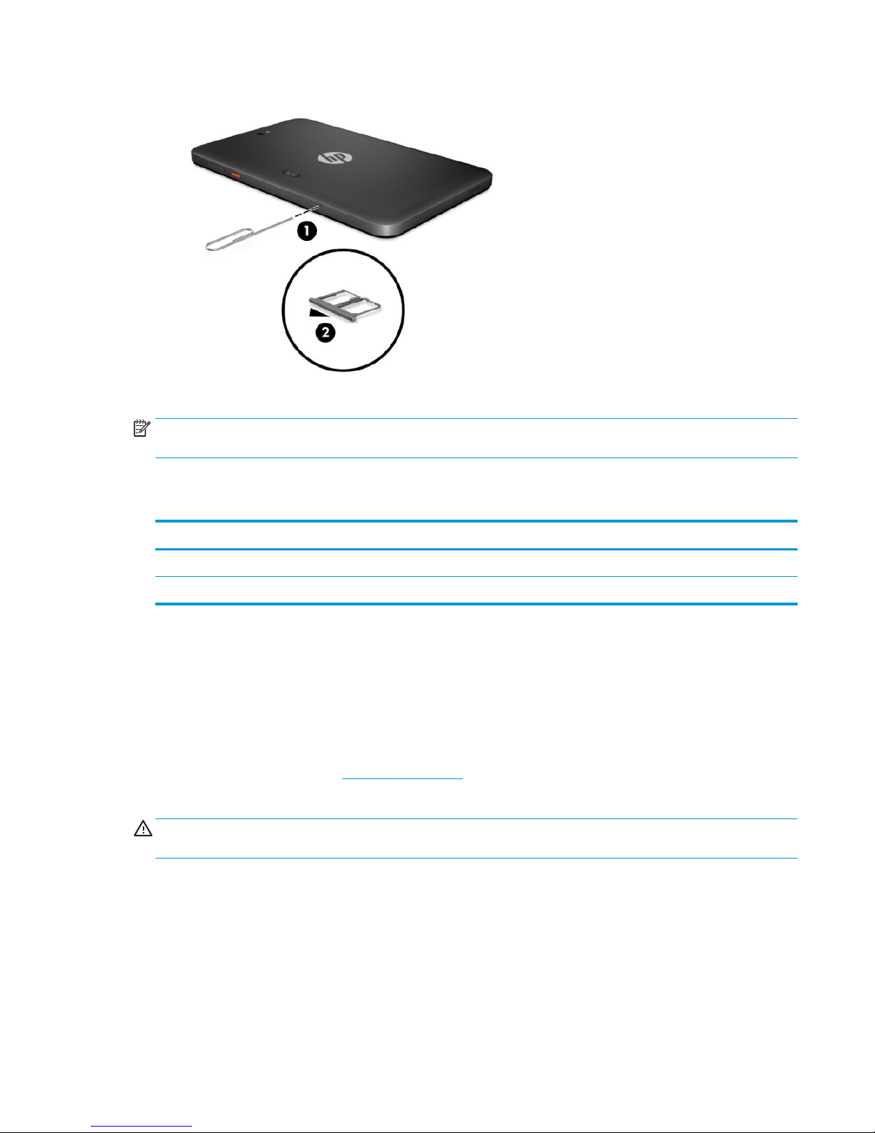
4. Remove the tray (2) from the voice tablet.
Reverse the steps to replace the tray.
NOTE: Be sure the card tray access hole is aligned with the access hole on the tablet before replacing the
tray.
Back cover
Description Spare part number
Back cover (includes camera lens) 926157-001
Back cover with logo (includes camera lens) 937866-001
Before removing the back cover, follow these steps:
1. Turn o the tablet. If you are unsure whether the tablet is o, turn the tablet on, and then shut it down
through the operating system.
2. Disconnect the power from the tablet by unplugging the power adapter cord from the tablet.
3. Disconnect all external devices from the tablet.
4. Remove the card tray (see Card tray on page 14).
Remove the back cover:
CAUTION: Before turning the voice tablet screen facedown, be sure that the work surface is clear of tools,
screws, and any other foreign objects. Failure to follow this caution can result in damage to the screen.
1. Place the tablet on a at surface, screen facedown.
2. Use a plastic pry tool (1) in the space between the back cover and screen, above the power on button.
3. Slide the tool (2) clockwise around the tablet to release the 18 plastics snaps securing the back cover to
the display panel assembly.
Back cover 15
Page 20
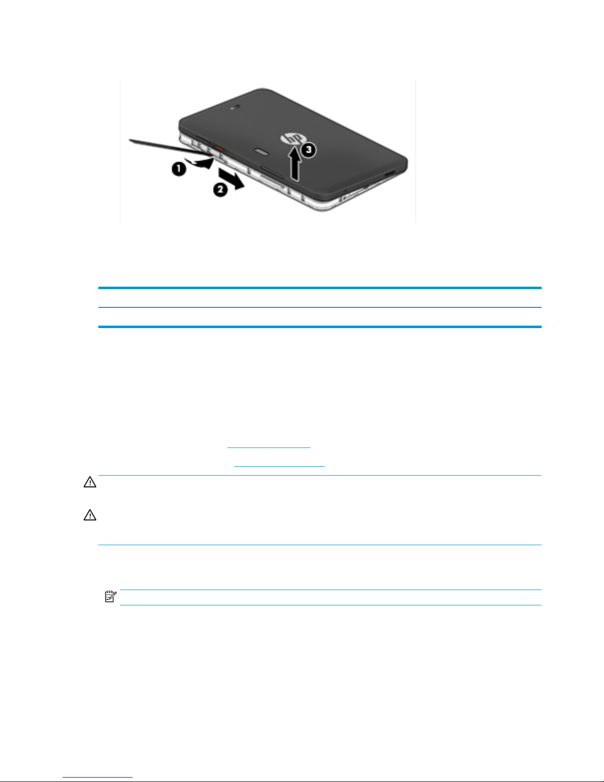
4. Lift the cover (3), and then remove the back cover.
Reverse this procedure to install the back cover.
Battery
Description Spare part number
Battery, 6000 mAH 3.8 V Lithium-Ion Polymer 928848-001
Before removing the battery, follow these steps:
1. Turn o the tablet. If you are unsure whether the tablet is o, turn the tablet on, and then shut it down
through the operating system.
2. Disconnect the power from the tablet by unplugging the power adapter cord from the tablet.
3. Disconnect all external devices from the tablet.
4. Remove the card tray (see Card tray on page 14).
5. Remove the back cover (see Back cover on page 15).
WARNING! To reduce potential safety issues, use only the battery provided with the tablet, a replacement
battery provided by HP, or a compatible battery purchased from HP.
CAUTION: Removing a battery that is the sole power source for the tablet can cause loss of information. To
prevent loss of information, save your work or shut down the tablet through the operating system before
disconnecting and removing the battery.
Remove the battery:
1. Remove the 2 M00 x 5.0 Phillips screws (1) securing the battery.
NOTE: Be careful not to bend the battery as you lift it.
16 Chapter 5 Removal and replacement procedures
Page 21
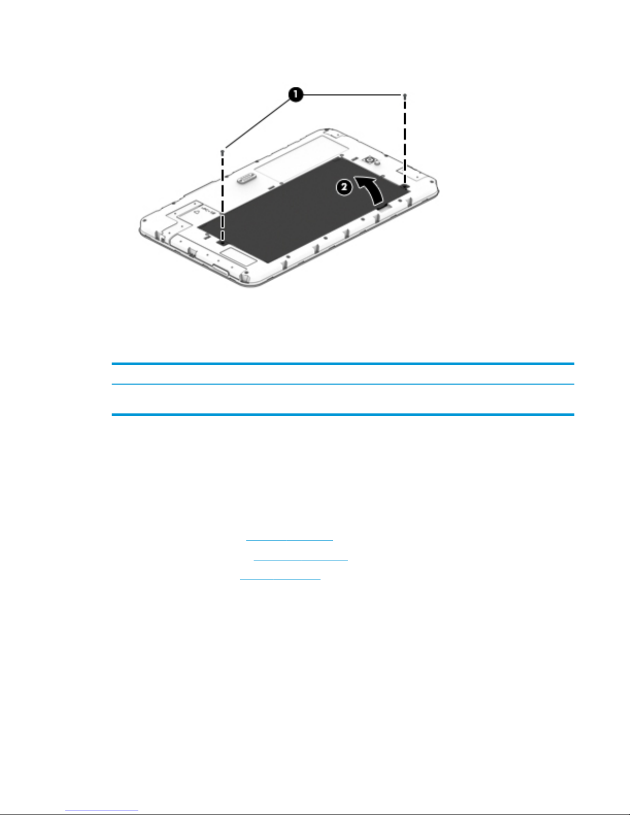
2. Use the battery notch (2) to lift and then remove the battery.
Reverse this procedure to install the battery.
Middle frame cover
Description Spare part number
Middle frame cover (includes graphite heat sink, camera light guide, Wi-Fi antennas, GPS, Bluetooth,
and ngerprint reader sensor)
926158-001
Before removing the middle frame cover, follow these steps:
1. Turn o the tablet. If you are unsure whether the tablet is o, turn the tablet on, and then shut it down
through the operating system.
2. Disconnect the power from the tablet by unplugging the power adapter cord from the tablet.
3. Disconnect all external devices from the tablet.
4. Remove the card tray (see Card tray on page 14).
5. Remove the back cover (see Back cover on page 15).
6. Remove the battery (see Battery on page 16).
Remove the middle frame cover:
1. Remove the 12 Phillips screws (1) securing the outside edges of the middle frame cover.
2. Remove the 5 Phillips screws (2) securing the inside edges of the middle frame cover.
Middle frame cover 17
Page 22
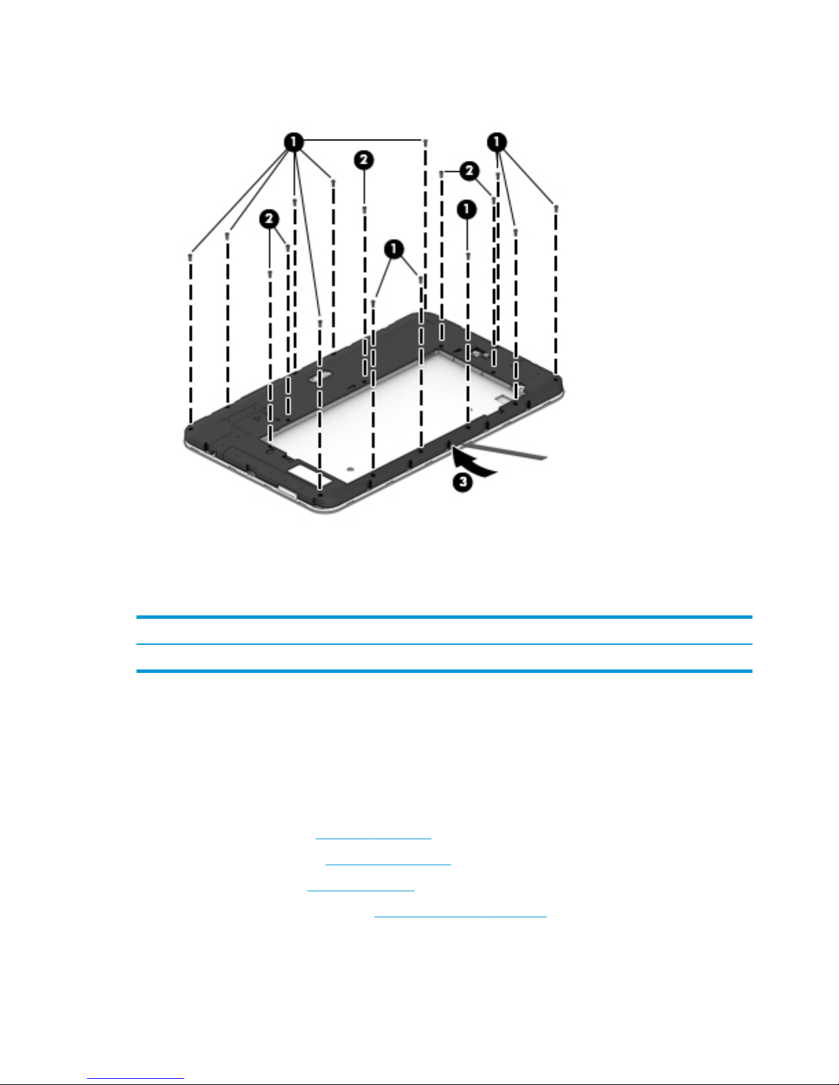
3. Insert a thin tool (3) in the thin side of the frame to release the snaps securing the frame, and then
remove the frame.
Reverse this procedure to install the middle frame cover.
Rear-facing webcam
Description Spare part number
Rear-facing webcam (includes cable) 926166-001
Before removing the rear-facing webcam, follow these steps:
1. Turn o the tablet. If you are unsure whether the tablet is o, turn the tablet on, and then shut it down
through the operating system.
2. Disconnect the power from the tablet by unplugging the power adapter cord from the tablet.
3. Disconnect all external devices from the tablet.
4. Remove the card tray (see Card tray on page 14).
5. Remove the back cover (see Back cover on page 15).
6. Remove the battery (see Battery on page 16).
7. Remove the middle frame cover (see Middle frame cover on page 17).
Remove the rear-facing webcam:
1. Disconnect the rear-facing webcam cable (1) from the system board.
18 Chapter 5 Removal and replacement procedures
Page 23
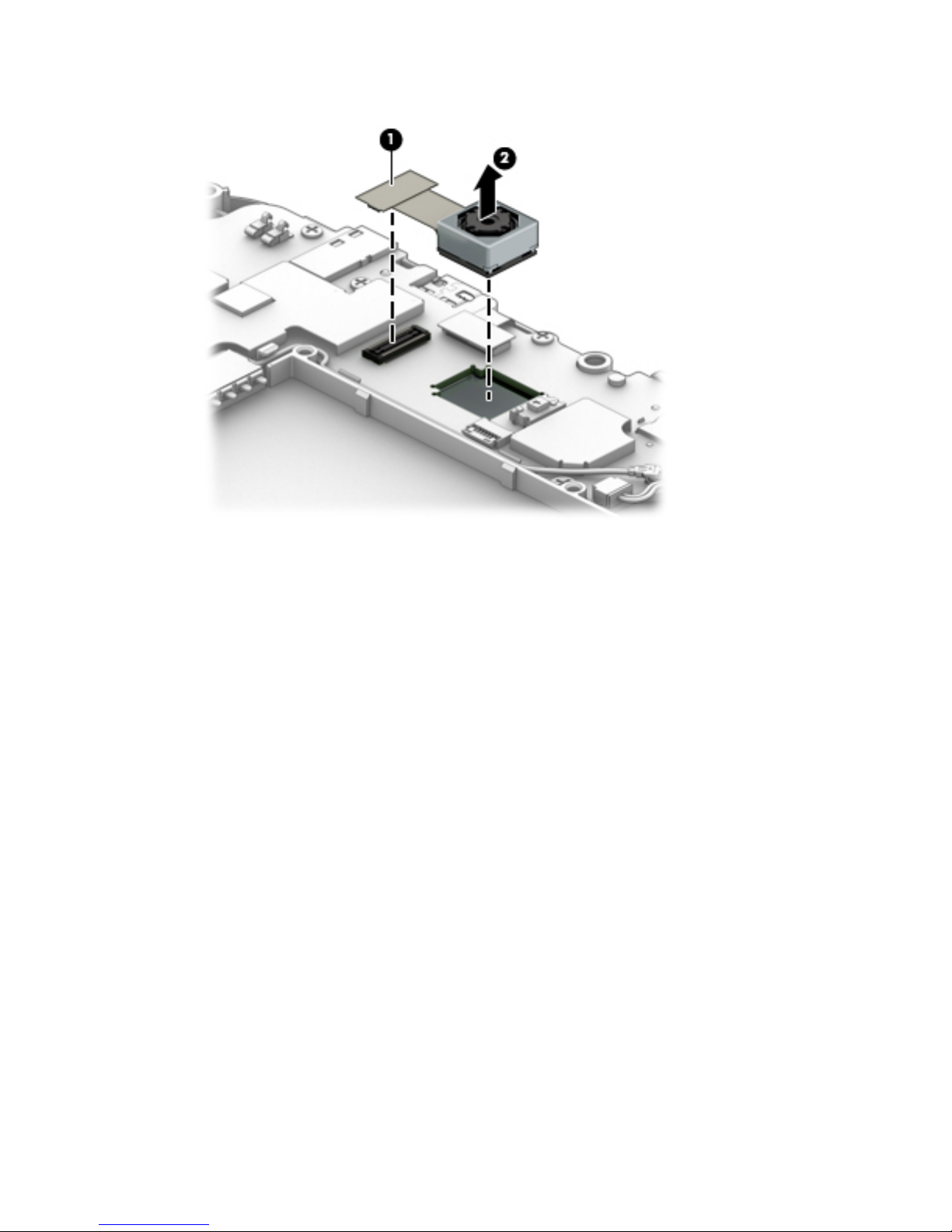
2. Lift and then remove the rear-facing webcam (2).
Reverse this procedure to install the rear-facing webcam.
Rear-facing webcam 19
Page 24
Antenna board
Description Spare part number
Antenna board 926160-001
Before removing the antenna board, follow these steps:
1. Turn o the tablet. If you are unsure whether the tablet is o, turn the tablet on, and then shut it down
through the operating system.
2. Disconnect the power from the tablet by unplugging the power adapter cord from the tablet.
3. Disconnect all external devices from the tablet.
4. Remove the card tray (see Card tray on page 14).
5. Remove the back cover (see Back cover on page 15).
6. Remove the battery (see Battery on page 16).
7. Remove the middle frame cover (see Middle frame cover on page 17).
Remove the antenna board:
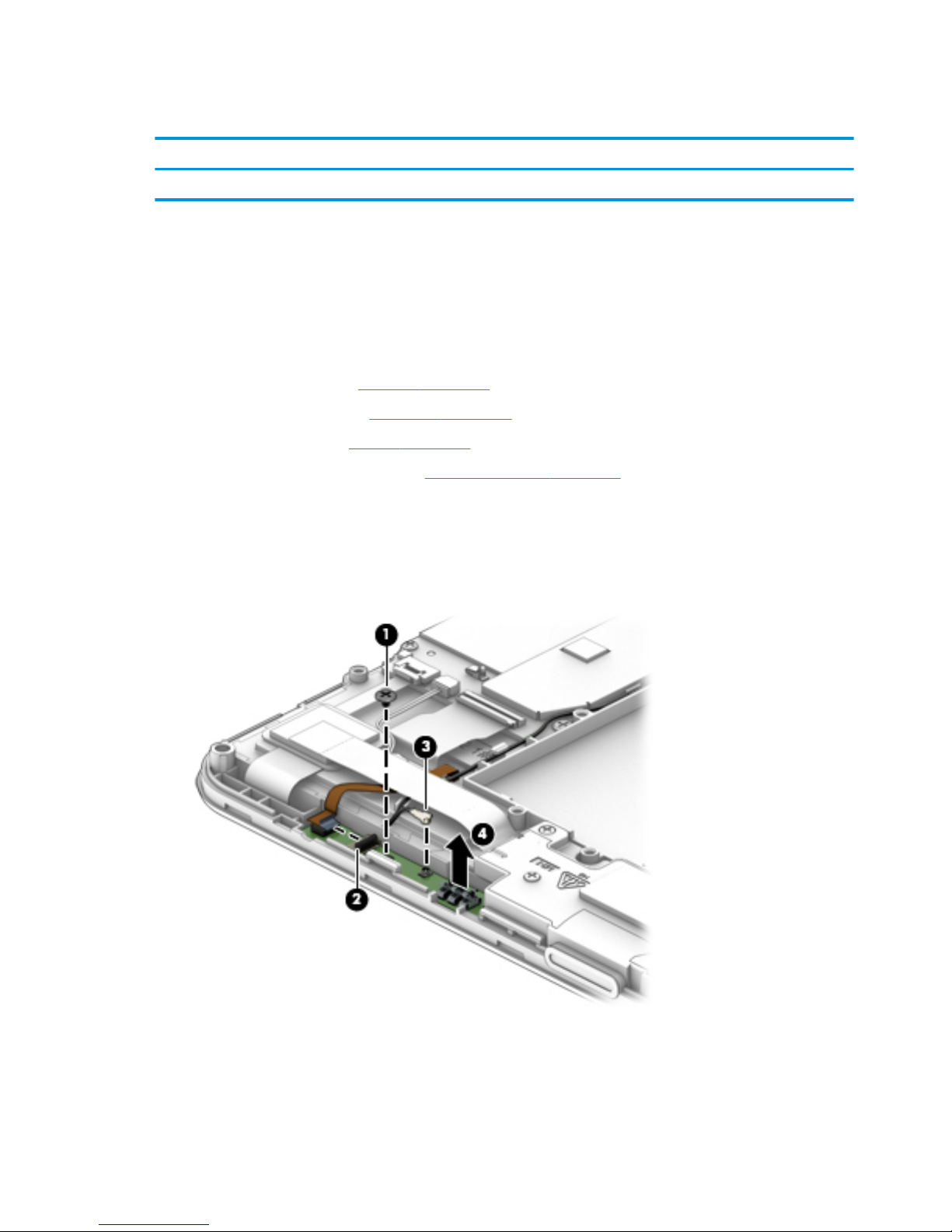
1. Remove the Phillips M00x3 screw (1) securing the antenna board.
2. Open the ZIF connector (2) to release the ribbon cable.
3. Detach the antenna (3) from the board, and then lift the board (4) to remove it.
Reverse this procedure to install the antenna board.
20 Chapter 5 Removal and replacement procedures
Page 25

Speaker
Description Spare part number
Speaker kit (includes speaker and cables) 926164-001
Before removing the speaker, follow these steps:
1. Turn o the tablet. If you are unsure whether the tablet is o, turn the tablet on, and then shut it down
through the operating system.
2. Disconnect the power from the tablet by unplugging the power adapter cord from the tablet.
3. Disconnect all external devices from the tablet.
4. Remove the card tray (see Card tray on page 14).
5. Remove the back cover (see Back cover on page 15).
6. Remove the battery (see Battery on page 16).
7. Remove the middle frame cover (see Middle frame cover on page 17).
Remove the speaker:
1. Remove the 4 Phillips M00x 5.0 screws (1) securing the speaker to the frame.
2. Disconnect the speaker cable (2) from the system board.
3. Remove the plastic protective tape (3), and then carefully route the cable (4) through the routing
channels and under the ribbon cable.
Speaker 21
Page 26
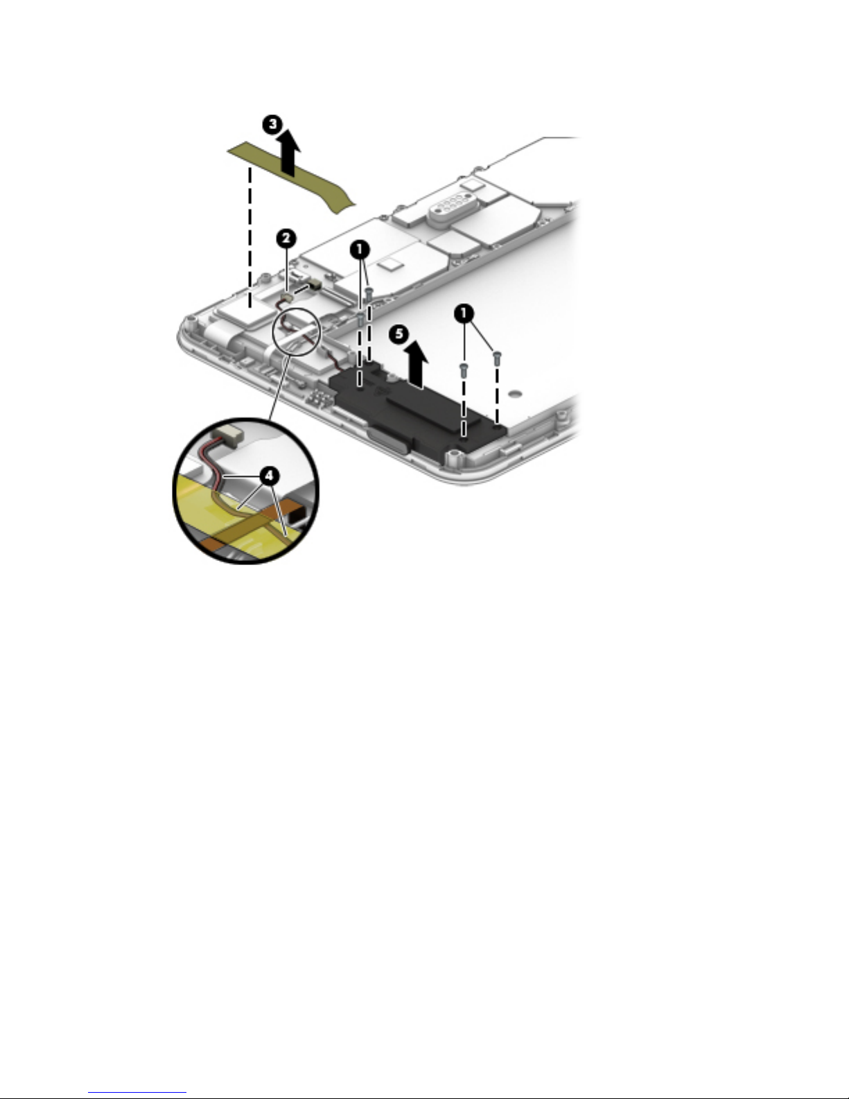
4. Lift and remove the speaker (5).
Reverse this procedure to install the speaker.
22 Chapter 5 Removal and replacement procedures
Page 27
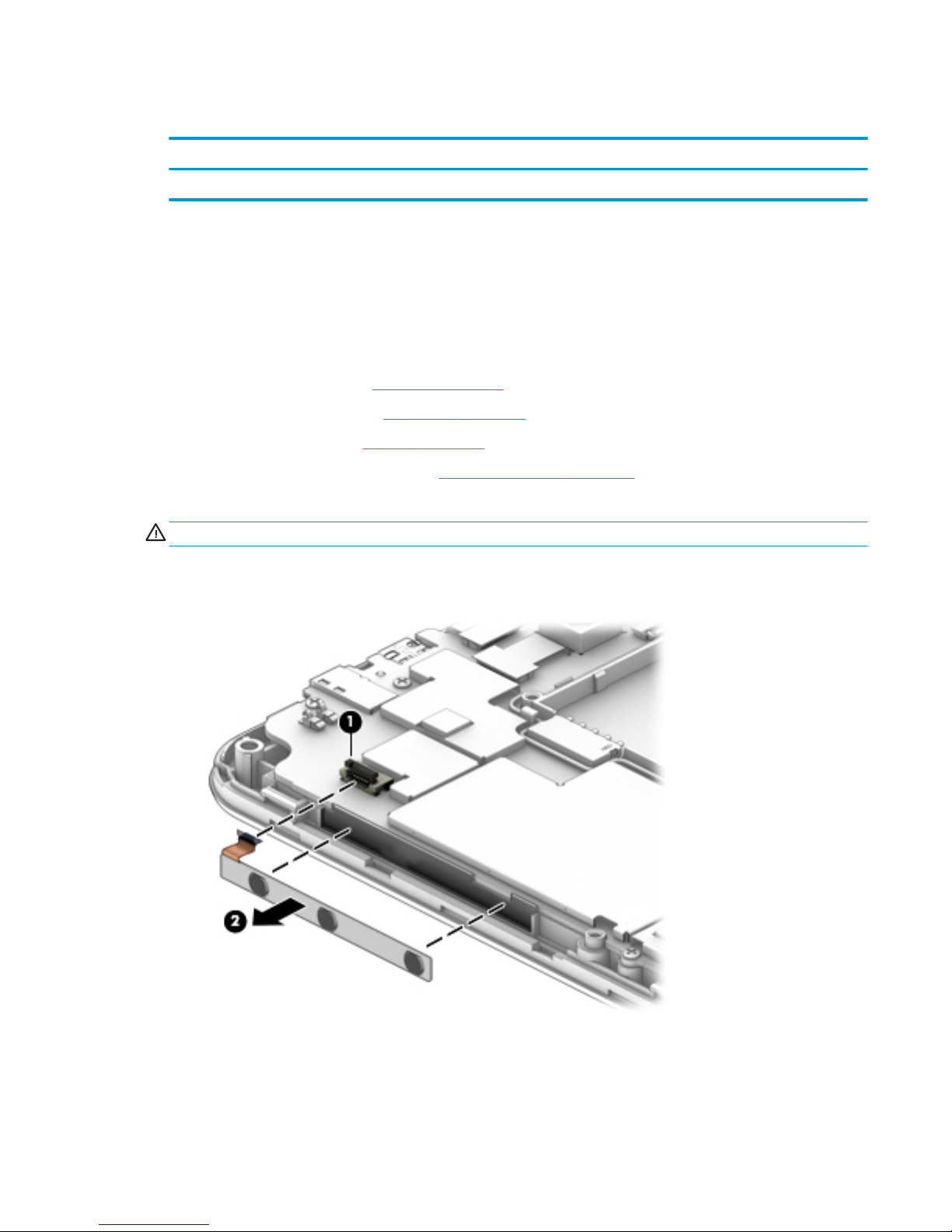
Volume and power button board
Description Spare part number
Volume and power button board 926161-001
Before removing the volume and power button board, follow these steps:
1. Turn o the tablet. If you are unsure whether the tablet is o, turn the tablet on, and then shut it down
through the operating system.
2. Disconnect the power from the tablet by unplugging the power adapter cord from the tablet.
3. Disconnect all external devices from the tablet.
4. Remove the card tray (see Card tray on page 14).
5. Remove the back cover (see Back cover on page 15).
6. Remove the battery (see Battery on page 16).
7. Remove the middle frame cover (see Middle frame cover on page 17).
Remove the volume and power button board:
CAUTION: Use care to prevent damaging the ZIF connector and ribbon cable.
1. Open the ZIF connector (1) to release the ribbon cable.
2. Remove the volume and power button board (2).
Reverse this procedure to install the volume and power button board.
Volume and power button board 23
Page 28

System board
Description Spare part number
System board (includes motor, coaxial line, and ngerprint reader strobe light) 926568-001
IMPORTANT: Before removing and replacing the system board, contact your HP service contact for
additional details on rmware, IMEI, and other system board replacement requirements.
Before removing the system board, follow these steps:
1. Turn o the tablet. If you are unsure whether the tablet is o, turn the tablet on, and then shut it down
through the operating system.
2. Disconnect the power from the tablet by unplugging the power adapter cord from the tablet.
3. Disconnect all external devices from the tablet.
4. Remove the card tray (see Card tray on page 14).
5. Remove the back cover (see Back cover on page 15).
6. Remove the battery (see Battery on page 16).
7. Remove the middle frame cover (see Middle frame cover on page 17).
Remove the system board:
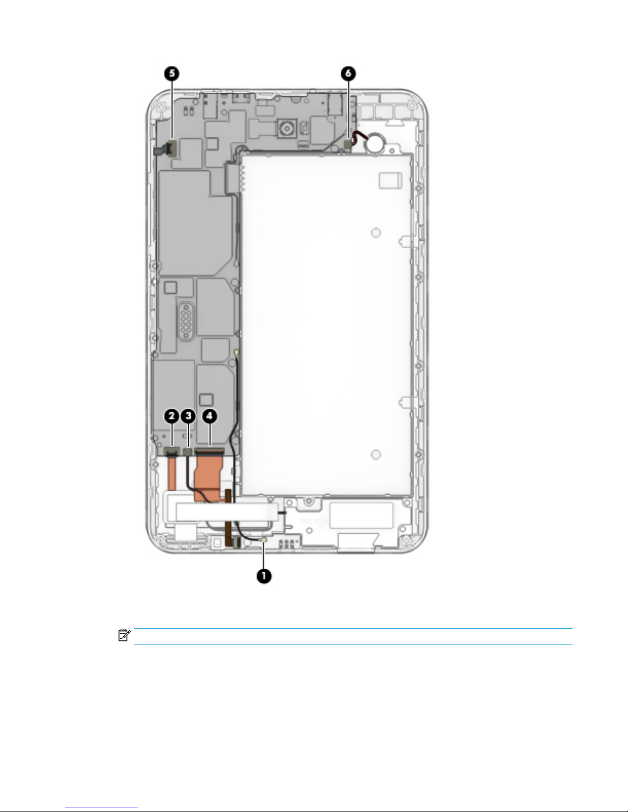
1. Release the system board ZIF connectors to which the following cables are connected, and then
disconnect the following cables from the system board. Use a thin tool to help release the cables.
(1) Antenna (release the plastic protective tape)
(2) Touch controller
(3) Speaker
(4) Display
(5) Button board
(6) Motor
24 Chapter 5 Removal and replacement procedures
Page 29
2. Remove the 5 black Phillips M00 x 3 screws (1) that secure the system board to the display panel
assembly.
NOTE: There is a magnet holding the board; you may have to gently pull the board to remove it.
System board 25
Page 30
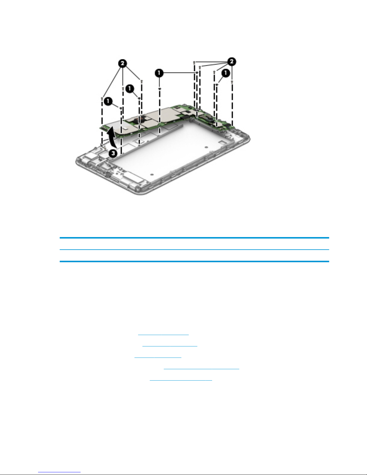
3. Remove the 7 Phillips M00x5 screws (2) that secure the system board to the display panel assembly,
and then remove the system board (3).
Reverse this procedure to install the system board.
Front-facing webcam
Description Spare part number
Front-facing webcam (includes cable) 926165-001
Before removing the front-facing webcam, follow these steps:
1. Turn o the tablet. If you are unsure whether the tablet is o, shut it down through the operating
system.
2. Disconnect the power from the tablet by unplugging the power adapter cord from the tablet.
3. Disconnect all external devices from the tablet.
4. Remove the card tray (see Card tray on page 14).
5. Remove the back cover (see Back cover on page 15).
6. Remove the battery (see Battery on page 16).
7. Remove the middle frame cover (see Middle frame cover on page 17).
8. Remove the system board (see System board on page 24).
Remove the front-facing webcam:
1. Place the system board face down, and then release the zero-insertion force (ZIF) connector (1) to which
the front-facing webcam cable is attached on the rear of the system board.
26 Chapter 5 Removal and replacement procedures
Page 31
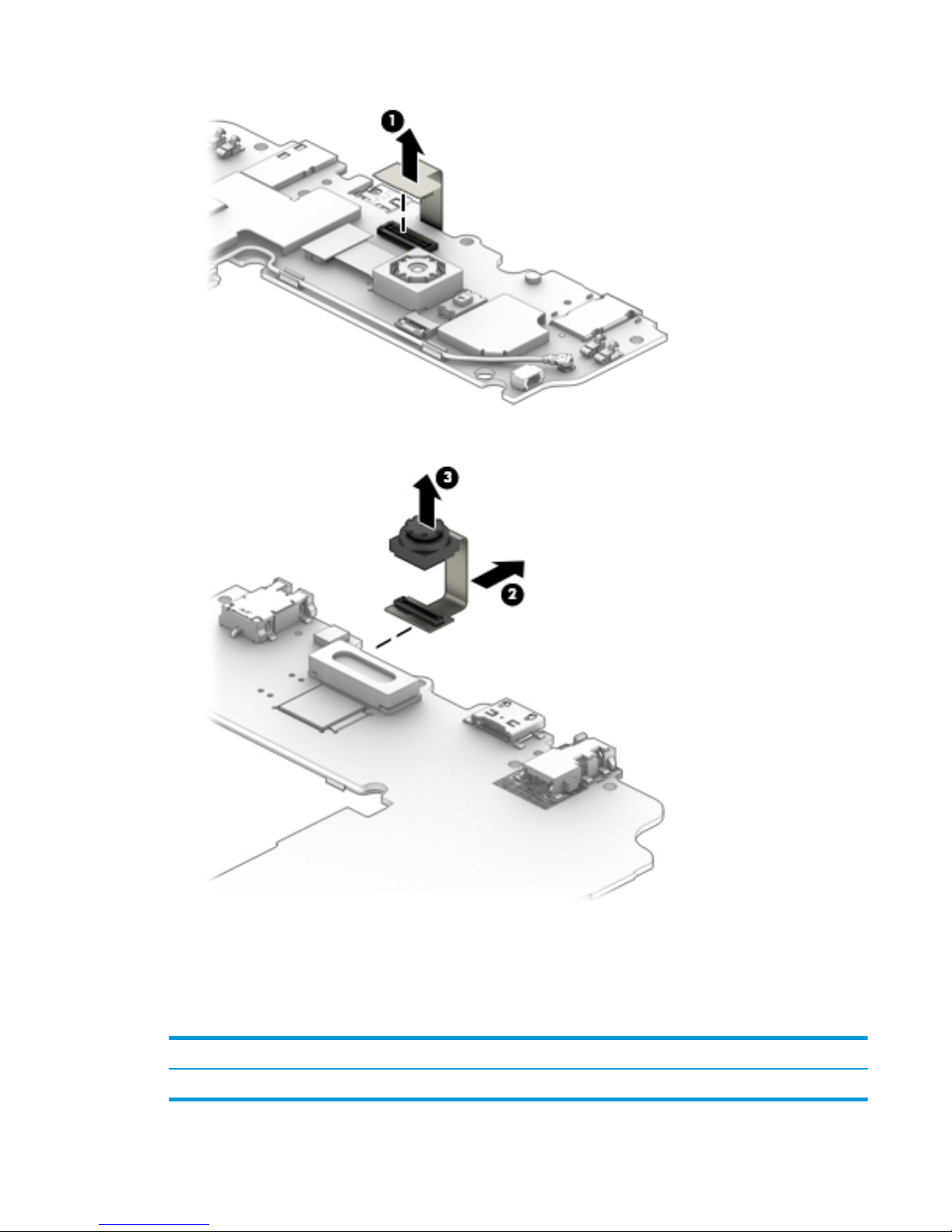
2. Place the system board face up, release the cable (2), and then lift up the webcam (3) to remove it.
Reverse this procedure to install the front-facing webcam.
Touchscreen display panel assembly
The touchscreen display panel assembly remains after disassembling the voice tablet.
Description
Spare part number
Touchscreen display panel assembly 926159-001
Touchscreen display panel assembly 27
Page 32

6 Specications
Metric
Dimensions (portrait orientation)
Height 21.07 cm
Width 12.8 cm
Depth 1.19 cm
Weight (lowest weight conguration) 0.489 kg
Input power
The tablet operates on DC power, which can be supplied by an AC or a DC power source. The AC power source must be rated at 100-240
V, 50/60 Hz, 0.3-1.0 A.
NOTE: The adapter included with your tablet is recommended for charging the tablet.
Temperature
Operating 0° C to 40° C
Special operating* –10° C to 50° C
Nonoperating ‑20° C to 60° C
Relative humidity (non-condensing)
Operating 0% to 90%
Nonoperating 0% to 95%
Maximum altitude (unpressurized)
Operating -15.24 to 4,572 m
NOTE: Applicable product safety standards specify thermal limits for plastic surfaces. The device operates well within this range of
temperatures.
* Test performed for two hours on a device with a fully charged battery that was stored for 30 minutes. Tested using continuous 720p
video playback, with middle level brightness, system audio level at 100%, and no adapter.
28 Chapter 6 Specications
Page 33

7 Backing up and recovering your data
Automatically updating apps
Some online marketplaces update your apps automatically. Some keep a record of your purchases as well as
your last synched settings. If you should need to perform a recovery on your tablet, this record will be
available to retrieve all of your settings, favorites, and apps.
NOTE: The auto-update feature is a setting in the online marketplace, not on your tablet.
Manually updating apps, widgets, and the operating system
HP recommends that you update your apps, widgets, and the operating system on a regular basis to the
latest versions. Updates can resolve issues and bring new features and options to your tablet. Technology is
always changing, and updating apps, widgets, and the operating system allows your tablet to run the latest
technology available. For example, older apps and widgets might not work well with the most recent
operating system.
If you download the latest versions of HP and third-party apps and widgets, the operating system will
download updates automatically and notify you when it is ready to install these updates. For more
information:
1. Go to http://www.hp.com/support, and follow the on-screen instructions to select your country and your
product.
2. Follow the on-screen instructions to access your Android operating system software.
Back up and reset
HP strongly encourages that you periodically back up your personal data on your tablet to another computer,
a dedicated storage device, or to the cloud using one of several commercially available solutions.
You can select preferences for backing up and restoring your data in case of loss.
1.
Swipe down twice from the top edge, and then touch the Settings icon .
2. Under Personal, touch Back up & reset.
3. Under Backup & reset, select one or more of the following:
●
Back up my data—Slide the switch to the right to enable backing up app data, Wi-Fi passwords,
and other settings to Internet servers.
●
Backup account—Select an email account for backing up data.
●
Automatic restore—Slide the switch to the right to enable backed up settings and data to be
restored when an app is reinstalled.
Automatically updating apps 29
Page 34

Factory data reset
Resetting with your tablet turned on
If your tablet starts normally, and if you are able to sign in to the owner account (the rst account added to
the tablet), follow the steps in this section.
To reset all settings and delete all data on your tablet:
1.
Swipe down twice from the top edge, and then touch the Settings icon .
2. Under Personal, touch Back up & reset.
3. Touch Factory data reset.
CAUTION: All data saved on your tablet is deleted when you perform a factory reset. All apps are
uninstalled. It may be possible to restore data in your email account. Back up all important les with an
external storage device or to the cloud using one of several commercially available solutions, before
resetting your tablet.
4. Touch RESET TABLET.
5. If you set a lock screen password for your tablet, enter your password when prompted.
6. Touch ERASE EVERYTHING to begin the reset.
The tablet turns o. When the reset is complete, the tablet starts.
Resetting with your tablet without the operating system
If your tablet does not start normally, or if you do not remember the lock screen password, you can reset the
tablet without turning it on.
CAUTION: All data saved on your tablet is deleted when you perform a factory reset. All apps are
uninstalled, but it may be possible to restore data in your email account. Back up all important les with an
external storage device or to the cloud using one of several commercially available solutions, before resetting
the tablet.
NOTE: The touch screen is disabled when the tablet is in recovery mode. Use the volume up (+) and volume
down (-) buttons to navigate up or down in the Recovery menu.
1. Charge the tablet for at least half an hour, and then disconnect the AC adapter from the tablet.
2. If a microSD card is installed in the tablet, remove the card before resetting the tablet.
3. With the tablet turned o, press and hold the power button and the volume up (+) button at the same
time.
4. When the Recovery menu appears, use the volume up (+) and volume down (-) buttons to highlight wipe
data/factory reset.
5. Press the power button to select.
The screen displays Conrm wipe of all user data? THIS CAN NOT BE UNDONE.
6. Use the volume up (+) and volume down (-) buttons to highlight Yes -- delete all user data.
30 Chapter 7 Backing up and recovering your data
Page 35

7. Press the power button to begin the reset.
A recovery system screen shows the reset process.
8. When the screen displays the message Data wipe complete, use the volume up (+) and volume down (-)
buttons to highlight Reboot system now, and then press the power button to select.
The tablet will restart.
Updating your tablet using an over-the-air (OTA) update
1. Turn o your tablet, and then connect it to AC power.
2. Turn on your tablet, and then connect to the Internet.
3.
Swipe down twice from the top edge, and then touch the Settings icon .
4. Touch About tablet, touch System updates, and then touch CHECK FOR UPDATE.
5. Follow the on-screen instructions to nish the process. Your tablet may restart as updates are applied.
Updating your tablet using an over-the-air (OTA) update 31
Page 36

Updating your tablet using a le-based update
NOTE: Before performing the following procedure, connect your tablet to AC power.
1. Download the latest operating system restore image for your tablet.
a. Go to http://www.hp.com/support, and follow the on-screen instructions to select your country
and your product.
b. Follow the on-screen instructions to access and download your Android operating system
software.
2. Locate update.zip and copy it to a microSD card.
3. Turn o your tablet, and then insert the microSD card containing the update.zip le.
4. To power on your tablet, press and hold the volume up (+) button and the power button.
5. Select apply update from sdcard.
6. Follow the on-screen instructions to nish the process and restart your tablet.
32 Chapter 7 Backing up and recovering your data
Page 37

8 Power adapter requirements
The wide-range input feature of the tablet permits it to operate from any line voltage from 100 to 120 volts
AC, or from 220 to 240 volts AC.
The 2-conductor power adapter included with the tablet meets the requirements for use in the country or
region where the equipment is purchased.
Power adapters for use in other countries and regions must meet the requirements of the country or region
where the tablet is used.
Requirements for all countries
The following requirements are applicable to all countries and regions:
●
The length of the adapter cord set must be at least 1.0 m (3.3 ft) and no more than 2.0 m (6.5 ft).
●
All power adapters must be approved by an acceptable accredited agency responsible for evaluation in
the country or region where the adapter will be used.
Requirements for specic countries and regions
Country/region Accredited agency
Argentina IRAM
Australia SAA
Austria OVE
Belgium CEBEC
Brazil ABNT
Canada CSA
Chile IMQ
Denmark DEMKO
Finland FIMKO
France UTE
Germany VDE
India BIS
Israel SII
Italy IMQ
Japan JIS
The Netherlands KEMA
New Zealand SANZ
Requirements for all countries 33
Page 38

Country/region Accredited agency
Norway NEMKO
The People's Republic of China CCC
Saudi Arabia SASO
Singapore PSB
South Africa SABS
South Korea KTL
Sweden SEMKO
Switzerland SEV
Taiwan BSMI
Thailand TISI
The United Kingdom ASTA
The United States UL
34 Chapter 8 Power adapter requirements
Page 39

9 Recycling
When a non-rechargeable or rechargeable battery has reached the end of its useful life, do not dispose of the
battery in general household waste. Follow the local laws and regulations in your area for battery disposal.
HP encourages customers to recycle used electronic hardware, HP original print cartridges, and rechargeable
batteries. For more information about recycling programs, see the HP Web site at http://www.hp.com/recycle.
35
Page 40

Index
A
About tablet 6
accessory connector, identifying 5
antenna board
removal 20
spare part number 9, 20
apps
updating 29
audio, product description 1
audio-out (headphone)/audio-in
(microphone) combo jack
identifying 3
B
back cover
removal 15
spare part number 9, 15
battery
removal 16
spare part number 9, 16
battery light 4
button
power 4
volume down 4
volume up 4
C
cable, spare part numbers 9
cables, service considerations 10
camera ash, identifying 5
cameras
identifying 4, 5
card tray
removing 14
components 3
back 5
front 3
connector, power 3
connectors, service considerations
10
D
display panel assembly, spare part
number 9
display panel, product description 1
download
app updates 29
operating system updates 29
widget updates 29
E
earpiece, identifying 4
electrostatic discharge 10
equipment guidelines 13
expansion slot, identifying 5
external expansion, product
description 1
F
factory data reset 29
front-facing webcam
removal 26
spare part number 9, 26
G
grounding guidelines 10
guidelines
equipment 13
grounding 10
packaging 12
transporting 12
workstation 12
H
HP Device Hub app 6
I
integrated camera ash,
identifying 5
J
jacks
audio-out (headphone)/audio-in
(microphone) combo 3
L
lights
battery 4
webcam 5
M
mass storage device, product
description 1
memory module, product
description 1
micro SIM card tray
removing 14
micro SIM/microSD card tray
spare part number 9
micro-B USB port, identifying 3
microphone, identifying 3
microphone, product description 1
microSD card tray
removing 14
microSD memory card reader,
identifying 4
microSD memory card size 4
middle frame cover
removal 17
spare part number 9, 17
model name 1
O
operating system, product
description 2
operating system, updating 29
P
packaging guidelines 12
plastic parts, service
considerations 10
port, identifying 3
ports
micro-B USB port 3
product description 1
power adapter
set requirements 33
power adapter, spare part numbers
9
power button board
removal 23
spare part number 9, 23
power button, identifying 4
power connector, identifying 3
36 Index
Page 41

power requirements, product
description 2
processor, product description 1
product description
audio 1
display panel 1
external expansion 1
mass storage 1
memory module 1
microphone 1
operating system 2
ports 1
power requirements 2
product name 1
sensor 1
serviceability 2
storage 1
video 1
wireless networking 1
product name 1
Product Notices, locating 5
R
rear-facing webcam
removal 18
spare part number 9, 18
reset, tablet 30
S
screw kit, spare part numbers 9
sensor, product description 1
service considerations
cables 10
connectors 10
plastic parts 10
serviceability, product description 2
SIM card
inserting 4
removing 4
SIM card slot, identifying 4
Sleep
exit 4
initiate 4
slots
microSD memory card reader 4
SIM card 4
speaker
identifying 4
removal 21
spare part number 9, 21
storage, product description 1
system board
removal 24
spare part number 9, 24
system information, locating 6
T
tablet
major components 7
specications 28
tools required 10
touchscreen display panel assembly
removal 27
spare part number 27
transporting guidelines 12
U
updating
apps 29
operating system 29
widgets 29
V
video, product description 1
volume button board
removal 23
spare part number 23
volume button, identifying 4
W
webcam
removal 18, 26
spare part numbers 9, 18, 26
wireless antennas, identifying 5
wireless networking, product
description 1
WLAN antennas, identifying 5
workstation guidelines 12
WWAN antennas, identifying 5
Index 37
 Loading...