

Page 1
Illustrated Parts & Service Map
HP Pro 3340/3348 Microtower Business PC
© 2011 Hewlett-Packard Development Company, L.P. The information contained herein is subject to change without notice. HP shall not be liable for technical or editorial errors or omissions contained herein.
Document Number 670586-001. 1st Edition October 2011.
Key Specifications
Processor Type Intel® Core i7, i5, i3, Pentium, Celeron
RAM Type
Maximum RAM 8 GB
Expansion Slots • (1) PCIe-x16
Chipset Intel H67
Graphics Adapter Integrated Intel HD graphics
Bays • (2) external 5.25-inch
I/O Interfaces
Preinstalled Operating
Systems
PC3-10600 DDR3 (1066/1333 MHz), non-ECC
• (1) PCIe-x1
• (2) PCI
• (2) internal 3.5-inch
Front: (2) USB 2.0, headphone
Rear: (6) USB 2.0, DVI-D, VGA, PS/2 keyboard and mouse,
audio in, audio out, RJ-45, serial
• Windows® 7 (Professional 32/64, Ultimate 64, Home Premium 64, Home Basic 64)
• FreeDos
• RedFlag Linux
Cables
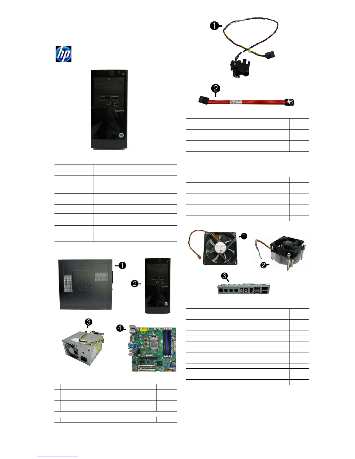
1 Power switch/LED assembly 657105-001
2 SATA cable, 165 mm 657102-001
* SATA cable, 370 mm 656833-001
* Adapter, DVI to VGA, HF 657401-001
* DMS-59 to Dual VGA cable 463023-001
* PATA to SATA power adapter 449283-001
*Not shown
Mass Storage Devices (not illustrated)
16X SATA DVD±RW drive 581600-001
DVD-ROM drive 581599-001
Blu-ray BD-RW SuperMulti DL Drive 617030-001
Bezel, optical drive 657852-001
1 TB, 7200 rpm hard drive, 6G 636930-001
750 GB, 7200 rpm hard drive, 6G 639363-001
500 GB, 7200 rpm hard drive, 6G 636929-001
250 GB, 7200 rpm hard drive, 6G 636927-001
Spare Parts
System Unit
1 Access panel 657104-001
2 Front bezel for use in the People’s Republic of China 670439-AA1
* Front bezel 668571-001
3 Power supply, 300W 656721-001
* Power supply, 250W, PFC 508466-001
System boards with thermal grease, alcohol pad, and CPU socket cover
4 System board for use in 3340/3348 models 663100-001
* Not shown
Miscellaneous Parts
1 Chassis fan 657103-001
2 Fan sink for use in models with Intel processors 667727-001
3 Front USB and I/O assembly 668572-001
* Speaker with rubber rivets 666885-001
* Card reader, 15-in-1 657099-001
* Card reader, bezel blank 657853-001
* Card reader, bezel 657854-001
* Mouse, PS2, optical, black 537748-001
* Mouse, USB, laser, black 570580-001
* Mouse, USB, optical, black 537749-001
* Rubber feet 530593-001
* Serial port kit 638815-001
* Printer port kit 638817-001
* USB powered speakers 636917-001
*Not shown
HP Pro 3340/3348, MT 670586-001 page 1
Page 2

Standard and Optional Boards
Memory modules (PC3-10600, CL9)
*1 GB
*2 GB
*4 GB
635802-001
635803-001
585157-001
Other boards
* ATI Radeon HD 6350 512-MB graphics adapter 637995-001
* ATI Radeon HD 6450 512-MB graphics adapter 637996-001
* ATI Radeon HD 6450 1-GB graphics adapter, PCIe x16 666330-001
* nVidia Quadro NVS300 PCIe x16 graphics card, 512 MB, PCIe x16 632486-001
* nVidia Quadro NVS300 PCIe x16 graphics card, 512 MB, PCIe x1 632827-001
* nVidia GeForce GT405 512-MB graphics adapter 657108-001
* Intel Gigabit NIC, includes bracket 490367-001
Intel Core i7 processors (include thermal material)
* 2600, 3.4 GHz, 8-MB L3 cache 638632-001
Intel Core i5 processors (include thermal material)
* 2500, 3.3 GHz, 6-MB L3 cache 638631-001
* 2400, 3.1 GHz, 6-MB L3 cache 638630-001
Intel Core i3 processors (include thermal material)
* 2120, 3.3 GHz, 3-MB L3 cache 638629-001
* 2100, 3.1 GHz, 3-MB L3 cache 638628-001
Intel Pentium Dual-Core processors (include thermal material)
* G850, 2.9 GHz, 3-MB L3 cache 655973-001
* G840, 2.8 GHz, 3-MB L3 cache 655972-001
* G620, 2.6 GHz, 3-MB L3 cache 655971-001
Intel Celeron Dual-Core processors (include thermal material)
* G540, 2.5 GHz, 2-MB L3 cache 666892-001
* G530, 2.4 GHz, 2-MB L3 cache 666891-001
* G440, 1.6 GHz, 1-MB L3 cache 666890-001
* Not shown
Diagnostic LEDs
LED Color LED Activity State/Message
Power Green On Computer on
Power Green 1 blink every 2 seconds Normal Suspend Mode
Power Red 1 blink every second followed
Power Red 3 blinks, 1 blink every second
Power Red 4 blinks, 1 blink every second
Power Red 5 blinks, 1 blink every second
Power Red 6 blinks, 1 blink every second
Power Red 7 blinks, 1 blink every second
Power Red 8 blinks, 1 blink every second
Power Red 9 blinks, 1 blink every second
Power Red 10 blinks, 1 blink every second
Power Red 11 blinks, 1 blink every second
none none System does not power on and
by a 2 second pause
followed by a 2 second pause
followed by a 2 second pause
followed by a 2 second pause
followed by a 2 second pause
followed by a 2 second pause
followed by a 2 second pause
followed by a 2 second pause
followed by a 2 second pause
followed by a 2 second pause
LEDs are not flashing
CPU thermal shutdown
Processor not installed
Power failure (power supply overload)
Pre-video memory error
Pre-video graphics error
System board failure (ROM
Invalid ROM based on Checksum
System powers on but is unable to boot
Bad option card
Current processor does not support a
feature previously enabled.
System unable to power on
System Board
System Board Connectors and Jumpers (component location may vary)
ATX_CPU CPU power connector
XU1 Processor socket INT_SPRK Speaker connector
CPU_ FAN
XMM1 Memory socket - Channel A PCI1 PCI expansion slot
XMM2 Memory socket - Channel B PCI2 PCI expansion slot
XMM3 Memory socket - Channel A PCIEX1 PCIe x1 expansion slot
XMM4 Memory socket - Channel B PCIEX16 PCIe X16 expansion slot
ATX_POWER Main power connector SPDIF_OUT1 S/PDIF audio connector
HOOD_SENSE Hood sensor connector AUDIO Audio connectors
BAT RTC battery socket LPT Parallel port connector
CLR_CMOS CMOS header PS2 Legacy keyboard and mouse
CLR_PASS Password header COMB Serial port connector
SATA2 1st optical drive SYS_FAN Fan connector
SATA0 1st hard drive VGA+COM1 Monitor+serial connector
SATA1 2nd hard drive DVI DVI connector
SATA3 2nd optical drive LAN+USB LAN + USB connector
F_PANEL Front panel connector USB USB connectors
F_USB1
Heat sink fan connector F_AUDIO Front audio connector
1st USB connector
F_USB2
2nd USB connector
connectors
HP Pro 3340/3348, MT 670586-001 page 2
Page 3
Common POST Error Messages
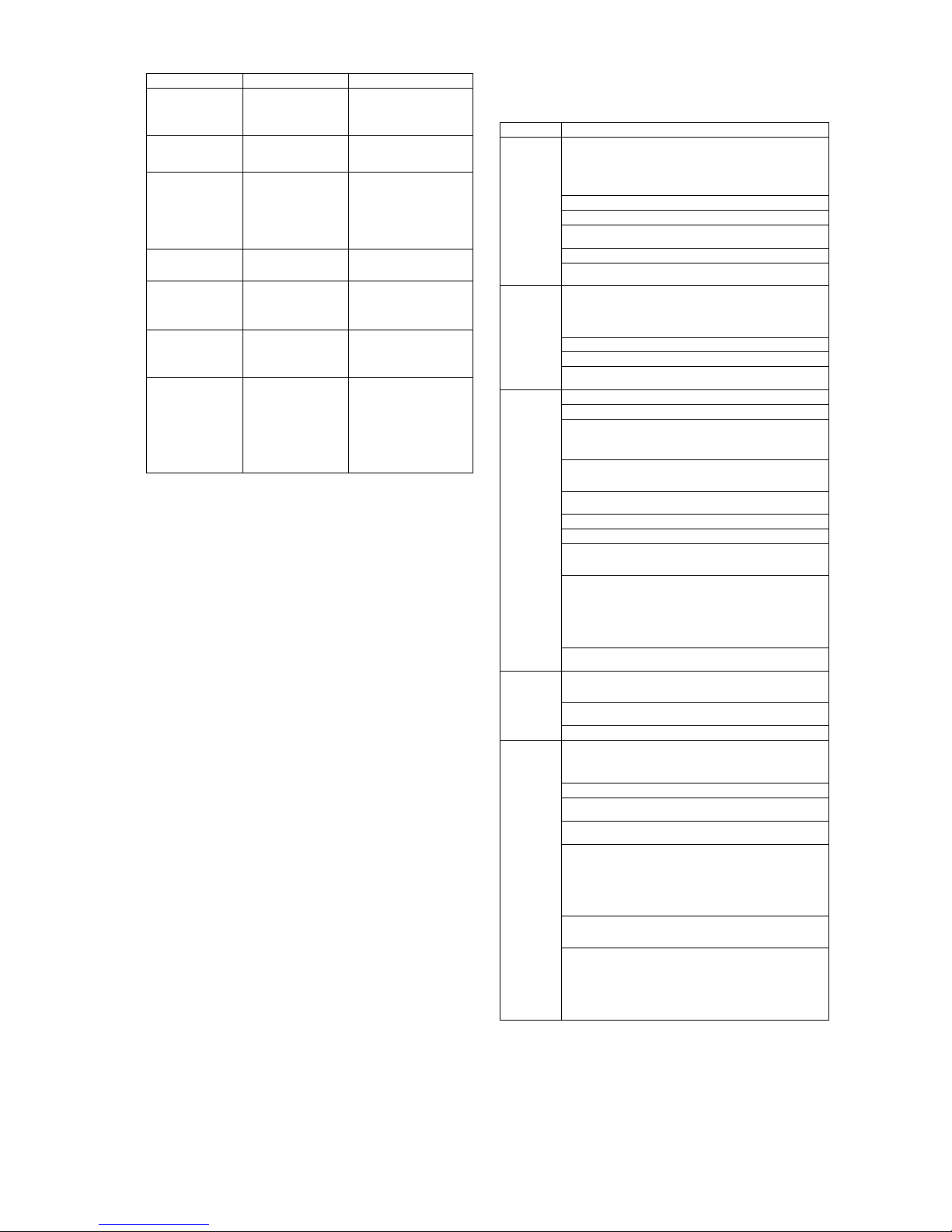
Screen Message Probable Cause Recommended Action
101-Option ROM Error 1. System ROM checksum
103-System Board
Failure
164-Memory Size Error
and
201-Memory Error
214-DIMM Configuration Warning
301-, 304-Keyboard error Keyboard failure. Check keyboard connection or
501-Display Adapter
Failure
1720-SMART Hard Drive
Detects Imminent Failure
error.
2. Expansion board option
ROM checksum
DMA, timers 1. Clear CMOS memory.
Incorrect memory configuration
Populated DIMM configuration is not optimized
Graphics display controller. 1. Reseat graphics card.
Hard drive is about to fail.
1. Verify ROM, reflash if required
2. Remove suspected card, reboot
3. Clear CMOS memory, reboot
4. Replace system board
2. Remove expansion boards.
3. Replace system board.
1. Run Setup (F10).
2. Check DIMMs for proper
seating, type, and HP
compatibility.
3. Remove DIMMs singularly and
reboot to isolate faulty DIMM.
4. Replace system board.
Rearrange the DIMMs so that
each channel has the same amount
of memory.
keys. Check connector for bent of
missing pins. Replace keyboard.
If 304, possible system board
problem.
2. Clear CMOS.
3. Check monitor connection.
4. Replace graphics card.
1. Determine if hard drive is giving
correct error message. Enter
Computer Setup and run the
Drive Protection System test
under
Storage > DPS Self-test
2. Apply hard drive firmware
patch if applicable.
3. Back up contents and replace
hard drive.
Password Security
Establishing a Setup or Power-On password:
1. Turn on or restart the computer.
2. As soon as the computer turns on, press the Esc key while “Press the ESC key for Startup
Menu” message is displayed at the bottom of the screen.
3. Press the F10 key to enter Computer Setup.
4. To establish Setup password, select Security > Setup Password and follow the instructions.
- or To establish a Power-On password, select Security > Power-On Password and follow the
instructions on the screen
5. Before exiting, click File > Save Changes and Exit.
Changing a Setup or Power-On password:
1. Turn on or restart the computer.
To change the Setup password, go to step 2.
To change the Power-on password, go to step 3.
2. As soon as the computer turns on:
- Press the Esc key while “Press the ESC key for Startup Menu” message is displayed.
- Press the F10 key to enter Computer Setup.
3. When the key icon appears, type your current password, a slash (/) or alternate delimiter
character, your new password, another slash (/) or alternate delimiter character, and your new
password again as shown:
current password/new password/new password.
NOTE: Type the new password carefully since the characters do not appear on the screen.
4. Press Enter.
The new password will take effect the next time the computer is restarted.
Deleting a Power-On or Setup password
1. Turn on or restart the computer.
To delete the Setup password, go to step 2.
To delete the Power-On password, go to step 3.
2. As soon as the computer turns on:
- Press the Esc key while “Press the ESC key for Startup Menu” message is displayed.
- Press the F10 key to enter Computer Setup.
3. When the key icon appears, type your current password followed by a slash (/) or alternate
delimiter character as shown. Example: currentpassword/
4. Press Enter.
Clearing CMOS
1. Turn off the computer and disconnect the power cord from the power outlet.
2. Remove the access panel.
3. On the system board, locate the CLR_CMOS header.
4. Remove the jumper from pins 2 and 3.
5. Place the jumper on pins 1 or 2.
6. Replace the jumper on pins 2 and 3.
7. Replace the chassis access panel and reconnect the power cord.
8. Turn on the computer and allow it to start.
Clearing Passwords
1. Turn off the computer and disconnect the power cord from the power outlet.
2. Remove the access panel.
3. On the system board, locate the CLR_PASS header.
4. Remove the jumper from pins 2 and 3.
5. Place the jumper on pins 1 or 2.
6. Replace the jumper on pins 2 and 3.
7. Replace the chassis access panel and reconnect the power cord.
8. Turn on the computer and allow it to start.
System Setup and Boot
Access the Setup Utility during the computer boot sequence by pressing the Esc key while
“Press the ESC key for Startup Menu” message is displayed at the bottom of the screen, and
then pressing the F10 key. If you do not press Esc at the appropriate time, you must restart the
computer and again press Esc when the monitor light turns green to access the utility.
Computer Setup Menu
Heading Option/Description
File System Information - Lists the following main system specifications:
Storage Device Configuration - Lists all installed BIOS-controlled storage devices.
Security Setup Password - Allows you to set and enable the setup (Admin) password.
.
Power OS Power Management (some models) - Allows you to enable/disable Run-
Advanced Power-On Options - Allows you to set:
• Product name
• SKU number (some models)
• Processor type/speed/stepping
• Cache size (L1/L2/L3)
About - Displays copyright notice.
Set Time and Date - Allows you to set system time and date.
Apply Defaults and Exit - Applies the selected default settings and clears
any established passwords.
Ignore Changes and Exit - Exits Computer setup without saving changes.
Save Changes and Exit - Saves changes to system configuration or default
settings and exits Computer Setup.
The following options are available:
• CD-ROM - Let you view model, firmware version, serial number
• Hard Disk - Let you view drive size, model, firmware version, serial
number. Also lets you set Emulation Type (hard disk or n one).
Storage Options - Allows you to set SATA Emulation - IDE or AHCI.
DPS Self-Test - Allows you to execute self-tests on ATA hard drives.
Boot Order - Allows you to specify boot order.
• Shortcut to Temporarily Override Boot Order
Power-On Password - Allows you to set and enable power-on password.
Password Options - When any password exists allows you to lock legacy
resources, enable/disable Setup Browse Mode, set password prompt, enable/
disable network server mode, specify password requirement for warm boot,
and set stringent passwords.
Device Security - Allows you to set Device Available/Device Hidden for:
embedded security devices, serial and parallel ports, system audio, network
controller, and SATA ports.
USB Security - Allows you to set Device Available/Device Hidden for front,
rear, and internal USB ports.
Slot Security - Allows you to disable any PCI or PCI Express slot.
Network Boot - Enables/disables boot from OS (NIC models only).
System IDs - Allows you to set Product name, serial number, UUID, SKU
number, family name, asset tag, feature byte, build ID, keyboard locale setting for system ID entry.
System Security (some models) - Allows you to enable/disable:
• Data Execution Prevention (enable/disable)
• Virtualization Technology (VTx/VTd) (enable/disable)
• Intel TXT (LT) (enable/disable)
• Embedded Security Device Support (enable/disable)
• OS management of Embedded Security Device (enable/disable)
• Reset of Embedded Security Device through OS (enable/disable)
DriveLock Security - Allows you to assign or modify a master or user password for hard drives.
time Power Management, Idle Power Savings, Unique Sleep State Blink
Rates.
Hardware Power Management - Allows you to enable/disable SATA bus
power management, S5 maximum power savings, and S5 Wake On LAN.
Thermal - Allows you to view CPU and system fan speeds.
• POST messages - Enable/disable
• After Power Loss - Off/on/previous state
• POST Delay - None, 5, 10, 15, or 20 seconds
BIOS Power-On - Allows you to set the computer to turn on at a preset time.
Bus Options (some models) - Allows you to enable/disable PCI SERR#
Generation and PCI VGA palette snooping.
Onboard Devices - Allows you to set resources for or disable onboard sys-
tem devices (serial port or parallel port).
Device Options - Allows you to set:
• Printer mode - Bi-Directional, EPP + ECP, Output Only)
• Num Lock State at Power-on - off/on
• Integrated Video - enable/disable
• Multi-Processor - enable/disable
• Hyper-threading - enable/disable
• NIC PXE Option ROM Download - enable/disable
VGA Configuration - Displayed only if there are multiple PCI video adapters in the system. Allows you to specify which VGA controller will be the
“boot” or primary VGA controller.
AMT Configuration - Allows you to set:
• AMT-enable/disable functions of the embedded Management Engine
(ME) such as Active Management Technology (AMT).
• Unconfigure AMT/ME-unconfigure any provisioned management settings for AMT.
• Watchdog Timer-set amount of time for a operating system and BIOS
watchdog alert to be sent if the timers are not deactivated.
• Installed memory size/speed/chan
• Integrated MAC Address
•System BIOS
• Chassis serial number
HP Pro 3340/3348, MT 670586-001 page 3
 Loading...