

Page 1

Illustrated Parts & Service Map
HP Pro 3005/3085 Business PC
Microtower Chassis
© 2009 Hewlett-Packard Development Company, L.P. The information con-
tained herein is subject to change without noti ce. HP shall not be liable for
technical or editorial errors or omissions contained herein. Intel, Pentium,
Intel Inside, and the Intel logo are trademarks or registered trademarks of the
Intel Corporation and its subsidiaries in the U. S. and other countries.
Document Number 600835-001. 1st Edition November 2009.
Key Specifications
Processor Type AMD Phenom™ II X3/X4 multi-core, AMD Athlon™ II X2/
RAM Type DDR3-SDRAM DIMMs, PC2-10600 (1333 MHz) non-ECC
Maximum RAM Supported 8 GB
Expansion Slots • (2) PCI 2.3
Graphics Adapter NVIDIA GeForce 9100 graphics controller with DX10 support
Chipset NVIDIA MCP78OV
Drive Support • (2) external 5.25-inch optical disk drives
I/O Interfaces Front: (2) USB 2.0 ports, headphone output, microphone jack
Operating Systems • Windows 7
Spare Parts
X3/X4 multi-core, AMD Sempron™
• (1) PCIe-x1
• (1) PCIe-x16
• (1) external 3.5-inch drive (for optional media reader or
Pocket Media drive)
• (2) internal 3.5-inch hard disk drives
Rear: (6) USB 2.0 ports, serial port, parallel port, PS2 keyboard and mouse, RJ-45 network interface, DVI-D and VGA
video interfaces, microphone jack, audio in/out jacks
• Windows Vista
• Windows XP Professional, Windows XP Home
• SuSE Linux Enterprise Desktop 11
• FreeDOS
• Red Flag Linux
Cables
1 Front I/O assembly 508463-001
2 Power switch/LED assembly 508464-001
3 SATA cable, 8.66-inch (22-cm), 2 straight ends 591600-001
* SATA hard drive cable with latch, 6.5 inch 448670-001
* SATA power dongle, 4 inch 449283-001
* DMS-59 to dual DVI 463024-001
*Not shown
Keyboards (not illustrated)
PS/2, Basic
USB, Standard
USB SmartCard
USB, Mini[e]
USB, low cost
Washable[g]
Adriatic[f] -BL1
Arabic[b][c][d] -171
Belgian[d] -181
BHCSY[b][d] -B41 Norwegian[d] -091
Czech[d] -221 Portuguese[d] -131
Danish[d] -081 Romanian[d] -271
Finnish[d] -351 Russian[d] -251
French[b][d] -051 S. Chinese[a] -AA1
French Arabic[d] -DE1
French Canadian[a] -121
German[d] -041 Swedish[d] -101
Greek[d] -151 Swiss[d] -111
Hebrew[b][d] -BB1 Taiwanese[a] -AB1
Hong Kong -AC1 Thailand[a] -281
Hungarian[d] -211 Turkish[d] -141
Iceland[a][c][d] -DD1 U.K.[d] -031
International English -L31
[a] not for 537924-xxx
[b] not for 537747-xxx
[c] not for 537746-xxx
[d] not for 537745-xxx
537745-xxx
537746-xxx
537747-xxx
535873-xxx
537924-xxx
577495-xxx
Italian[d] -061
Japanese[a] -291
Korea n -KD1
Slovakian[d] -231
Spanish[d] -071
United States[a] -001
[e] 535873-xxx only for -201, -AA1, L31
[f] 537747-xxx only
[g] 577495-xxx only for -001, -121
System Unit
1 Access panel 586372-001
2 Power supply, 300W, NPFC 463318-001
* Power supply, 300W, 85% (APJ only) 575437-001
* Power supply, 300W, PFC 508467-001
* Power supply, 250W, PFC 508466-001
3 Chassis not spared
4 Front bezel for use in HP Pro 3005 591599-001
* Front bezel for use in HP Pro 3085 591606-001
* 5.25-inch bezel blank 536306-001
* 3.5-inch bezel blank 583094-001
HP Pro 3005/3085 Illustrated Parts & Service Map, MT chassis 600835-001 page 1
Mass Storage Devices (not illustrated)
Blu-ray Disc ROM with SuperMulti DVD±R/RW DL Drive 581601-001
DVD±RW and CD-RW SuperMulti DL Combo Drive with LightScribe 581600-001
DVD-ROM drive 581599-001
500 GB SATA hard drive, 58 6720-001
250 GB SATA hard drive 586719-001
250-GB external USB hard drive 586383-001
160 GB SATA hard drive 586718-001
Page 2

Standard and Optional Boards
System boards with thermal grease, alcohol pad, and CPU socket cover
1 System board 591598-001
Memory modules (PC3-10600, CL9)
21 GB
*2 GB
*4 GB
Other boards
* Agere International 56K LSI v92 modem, includes bracket 490689-001
* ATI Radeon HD4350 (RV710) PCIe x16 graphics card, 512 MB 578368-001
* ATI Radeon HD4550 (RV710) PCIe x16 graphics card, 256 MB 538051-001
* ATI Radeon HD4550 (RV710) PCIe x16 graphics card, 512 MB 584217-001
* ATI Radeon HD4650 (RV730) PCIe x16 graphics card, 1 GB, 15 month
warranty, EMEA only
* GeForce GT205 512-MB PCIe graphics card (for use in China only) 589145-001
* GeForce GT315 512-MB PCIe graphics card (for use in China only) 589146-001
* GeForce GT230 1.5-GB PCIe graphics card 586381-001
* GeForce GT230 1.5-GB PCIe graphics card (APJ only) 590812-001
* GeForce GT210 512-MB PCIe graphics card 586382-001
* 802.11b/g/n WLAN PCIe adapter 538048-001
* Intel Gigabit NIC, includes bracket 490367-001
* HP FireWire IEEE 1394 PCI card, FH 515182-001
* Serial/parallel port PCI adapter 321722-001
AMD Athlon II X2 processors with alcohol pad and thermal grease:
* X4 630, quad core, 2-MB L2 cache, 2.8 GHz 586735-001
* X4 620, quad core, 2-MB L2 cache, 2.6 GHz 586734-001
* X3 435, quad core, 2-MB L2 cache, 2.9 GHz 586733-001
* X3 425, quad core, 2-MB L2 cache, 2.7 GHz 586732-001
* X2 250, dual core, 2-MB L2 cache, 3.0 GHz 584 221-001
* X2 245, dual core, 2-MB L2 cache, 2.9 GHz 586 731-001
* X2 240, dual core, 2-MB L2 cache, 2.8 GHz 584 222-001
* X2 215, dual core, 2-MB L2 cache, 2.75 GHz 586730-001
AMD Phenom II processors with alcohol pad and thermal grease:
* X4 945, quad core, 2-MB L2 cache, 3.0 GHz 586741-001
* X4 925, quad core, 2-MB L2 cache, 2.8 GHz (6-MB L3 cache) 584219-001
* X4 820, quad core, 2-MB L2 cache, 2.8 GHz (4-MB L3 cache) 586739-001
* X4 805, quad core, 2-MB L2 cache, 2.5 GHz 585156-001
* X3 720, triple core, 1.5-MB L2 cache, 2.8 GHz 581073-001
* X2 550, dual core, 1-MB L2 cache, 3.1 GHz 580 749-001
* X2 545, dual core, 1-MB L2 cache, 3.0 GHz 584 220-001
AMD Sempron processors with alcohol pad and thermal grease:
* 140, single core, 1-MB L2 cache, 2.7 GHz 590132-001
* Not shown
576109-001
576110-001
585157-001
578174-001
Miscellaneous Parts
1 Heatsink with alcohol pad and factory-applied thermal grease 591601-001
2 Chassis fan 438741-001
3 Internal speaker 463316-001
*
Media card reader 480032-001
*
Hood sensor 534484-001
*
PCI slot cover 580507-001
*
USB powered speakers 571536-001
*
Serial port 530599-001
*
Printer port 465339-001
* Foot kit 530593-001
* Mouse, optical 537748-001
* Mouse, laser 570580-001
* Rear I/O cover 592507-001
*Not shown
System Board
System Board Connectors and Jumpers (component location may vary)
FRNT_AUD Front panel connector FLPY Floppy drive connector
PCI2 PCI slot 2 IDE IDE connector
PCI1 PCI slot 1 PWR Main power connector
X16PCEXP PCIe X16 connector CMOS CMOS jumper
X1PCIEXP1 PCIe X1, slot 1 SATA1 1st SATA optical drive
AUD Double stack audio connector SATA2 1st SATA hard drive
RJ45/USB Stacked RJ-45/USB connectors JFP1 Power switch connector
DVI/VGA Stacked DVI/VGA connector SATA3 2nd SATA optical drive
USB USB connector SATA4 2nd SATA hard drive
SER Serial port FRNT_USB2 2nd USB connector
PS2 PS/2 connectors PSWD Password header
PWRCPU CPU power connector HSENSE Hood sensor connector
CHFAN1 System fan connecto r FRNT_USB1 1st USB connector
PROCESSOR
CPUFAN CPU/heat sink fan connector PAR Parallel port connector
DIMM1 Memory socket 1 COMB 2nd media reader connec-
DIMM2 Memory socket 2 SPDIF OUT Digital line-in/line-out
DIMM3 Memory socket 3 SPKR Speaker connector
DIMM4 Memory socket 4
Processor slot MEDIA
Media card reader connector
tor
audio connector
HP Pro 3005/3085 Illustrated Parts & Service Map, MT chassis 600835-001 page 2
Page 3
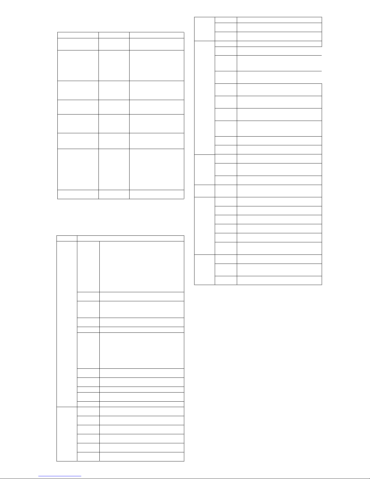
POST Audible Codes
Beeps Meaning Recommended Action
1 short beep and 1 long beep
followed by a three second
pause
2 short beeps and 1 long
beep followed by a three
second pause
3 short beeps and 1 long
beep followed by a three
second pause
1 short beep followed by a
one second pause
2 short beeps followed by a
three second pause
3 short beeps followed by a
three second pause
4 short beeps followed by a
three second pause
5 short beeps followed by a
three second pause
Bad memory or
memory configuration error.
No graphics card
installed or graphics
card initialization
failed.
CPU configuration
error or invalid CPU
detected before
graphics card initialized.
No optical drive
found.
No CD found. 1. Check the type of drive that you are
Flashing not ready
(missing utility or
BIOS image file,
etc.)
Flashing operation
has failed (checksum
error, corrupted
image, etc.)
BIOS recovery was
successful
Check that the memory modules have
been installed correctly and that proper
modules are used.
For systems with a graphics card:
1. Reseat the graphics card. Power on
the system.
2. Replace the graphics card.
3. Replace the system board.
For systems with integrated graphics,
replace the system board.
1. Upgrade the BIOS to proper version.
2. Change the processor.
1. Check cable connections.
2. Run the Computer Setup utility and
ensure the device port is enabled.
using and use the correct media
type.
2. Replace the CD with a new one.
Upgrade the BIOS to proper version.
1. Verify the correct ROM.
2. Flash the ROM if needed.
3. If an expansion board was recently
added, remove it to see if the problem remains.
4. Clear CMOS.
5. If the message disappears, there may
be a problem with the expansion
card.
6. Replace the system board.
No action required.
Computer Setup
Basic system information regarding system information, setup, power management, hardware,
and passwords is maintained in the Setup Utility held in the system ROM. The Setup Utility is
accessed by pressing the F10 key when prompted (on screen) to do so during the boot sequence.
If the screen prompt opportunity is missed, a restart will be necessary...
Computer Setup Menu
Heading Option / Description
Main System Infor-
Advanced AMD NX
mation
Set Time and
Date
SATA Port 1
SATA Port 2
SATA Port 3
SATA Port 4
SATA Controller
PATA Master For each, if PATA is used, allows you to:
PATA Slave • Run SMART self-test for select ed channel: SMART Sta-
PATA C ontroller
Onboard FDC
Controller
Drive A Allows you to set to None or 1.4M, 3.5 in.
Halt On Allows you to set POST error behavior to: all errors, no
POST Delay Allows you to set POST delay to 0, 5, 10, 15, or 30 seconds
Function
Init Display
First
iGPU Frame
Buffer Size
Onboard HD
Audio
OnChip USB
Controller
USB Legacy
Support
Lists the following main system specifications:
• Product Name
• SKU Number
• Processor Type
• Processor Speed
• CPUID/PatchID
• Cache Size
• Memory Size
• Integrated MAC
• System BIOS
• Chassis Serial Number
•Asset Tag Number
• UUID
Allows you to set system time and date.
For each allows you to:
• Run HDD self-test for selected channel: SMART Status
Check, Short Self-Test, Extended Self-Test
• View vendor, size, and firmware
Allows you to disable/enable the SATA Controller.
tus Check, Short Self-Test, Extended Self-Test
• Auto-detect HDD size and head
• Set PATA Master/Slave device details on selected channel
to None, Auto, Manual
• Set access mode on selected channel to CHS, LBA,
Large, Auto
• View Firmware, Capacity, Cylinder, Head, Precomp,
Landing Zone, Sector
Allows you to disable/enable the PATA Controller.
Disable/enable the diskette drive controller.
errors, all but keyboard.
Allows you to disable/enable the processor’s No Execute Feature.
Allows you to set primary display device to PCI slot, OnChip
VGA, or PCIEx.
Allows you to specify the onboard VGA shared memory size
to Auto, 64MB, 128MB, 256MB.
Allows you to disable/enable onboard HD audio.
Disables/enables the universal host controller interface fo r
USB (Universal Serial Bus).
Disable/enable (USB keyboard, mouse, and flash media).
Onboard LAN Disable/enable onboard LAN controller.
Onboard LAN
Boot ROM
Onboard
Boot F9 Boot Menu Disables/enables F9 Boot Menu.
Power After AC
PC Health Chassis
Exit Save and Exit
Serial Port 1
F10 Setup
Prompt
F11 Recovery Disables/enables F11 Recovery and provides the option of
F12 Boot
from LAN
Prompt
Hard Disk
Boot Seq.
Optical Drive
Boot Seq.
Network Boot
Seq.
First, Second,
Third, and
Fourth Boot
Device
Set Supervisor
Password
BIOS Write
Protection
Power Loss
Wak e on P CI
Device from
S5
RTC R esum e
Alarm
Opened Warning
System Fan
Fail Check
Smart Fan
Function
Current CPU
Temperature
Current System Temp
Current CPU
Fan Speed
Current System Fan
Speed
Setup
Discard
Changes and
Exit
Load Optimized defaults
Disable/enable the boot ROM of the onboard LAN chip.
Allows you to select: Disabled, 3F8/IRQ4, 2F8/IRQ3, 3E8/
IRQ4, or 2E8/IRQ3.
Disable/enable F10 Setup prompt on the logo screen.
showing the F11 Recovery prompt message on the logo
screen. Choose from the following: Disabled, Enabled no
prompt, Enabled and prompt.
Disables/enables the F12 Boot from LAN prompt message on
the logo screen.
Allows you to specify the order of attached hard drive devices
(USB HDD or USB flash media). The first attached drive in
the order has priority and is recognized as drive C.
Allows you to specify the order in which attached optical
drives (including USB ODD) are checked for a bootable operating system image.
Allows you to specify the order in which network devices
(including UP NIC cards) are checked for a bootable operating system image.
Allows you to specify which devices will boot in which
sequence or to disable any of the four: removable, CDROM,
hard disk, or network.
Allows you to establish a password to enter Computer Setup
Disables/enables BIOS upgrading.
Allows you to select system power loss behavior: Off, On,
Last State.
Disables/enables waking up from S5 by PCI device.
Disables/enables RTC (real-time clock) alarm.
Allows you to disable/enable the chassis intrusion function
and clear the intrusion warning: Disabled, Enabled, Clear.
Disables/enables detection of system fan during POST.
Disables/enables Smart Fan functionality. Enabling optimizes
fan control for best acoustic behavior.
View only
View only
View only
View only
Allows you to save current settings and exit Computer Setup.
Allows you to exit Computer Setup without saving changes.
Allows you to reset Computer Setup to factory defaults.
Password Security
Resetting the password jumper
1. Shut down the operating system properly, then turn off the computer and any external devices,
and disconnect the power cord from the power outlet.
2. With the power cord disconnected, press the power button again to drain the system of any
residual power.
3. Remove the access panel.
4. Locate the header and jumper labeled PSWD.
5. Remove the jumper.
6. Plug in the computer and turn on power.
7. When you see the HP logo screen, turn off the computer. This clears the current passwords.
8. Replace the jumper to its original position.
9. Replace the access panel.
10.reconnect external equipment.
11.Plug in the computer and turn on power. Allow the operating system to start.
Resetting the CMOS jumper
1. Turn off the computer and any external devices, and disconnect the power cord from the
power outlet. The power must be disconnected from the system to clear CMOS.
2. Disconnect the keyboard, monitor, and any other external equipment connected to the
computer.
3. Remove the access panel.
4. Locate the header and jumper labeled CMOS.
5. Remove the CMOS jumper from pins 1 and 2 and pu t the jumper on pins 2 and 3. This clears
CMOS.
6. Put the jumper back on pins 1 and 2.
7. Replace the access panel.
8. Reconnect the external equipment.
9. Plug in the computer and turn on power.
NOTE: Use Computer Setup to reset any special system setups along with the date and time.
HP Pro 3005/3085 Illustrated Parts & Service Map, MT chassis 600835-001 page 3
 Loading...