

HP Presario F500 Maintenance And Service Manual

Compaq Presario F500 Notebook PC
Maintenance and Service Guide

© Copyright 2007 Hewlett-Packard
Development Company, L.P.
Microsoft, Windows, and Windows Vista are
either trademarks or registered trademarks of
Microsoft Corporation in the United States
and/or other countries. AMD, Sempron,
Turion, and combinations thereof, are
trademarks of Advanced Micro Devices, Inc.
Bluetooth is a trademark owned by its
proprietor and used by Hewlett-Packard
Company under license.
The information contained herein is subject to
change without notice. The only warranties
for HP products and services are set forth in
the express warranty statements
accompanying such products and services.
Nothing herein should be construed as
constituting an additional warranty. HP shall
not be liable for technical or editorial errors
or omissions contained herein.
This guide is a troubleshooting reference used
for maintaining and servicing the computer. It
provides comprehensive information on
identifying computer features, components,
and spare parts; on troubleshooting computer
problems; and on performing computer
disassembly procedures.
First Edition: January 2007
Document Part Number: 440524-001

Table of contents
1 Product description
2 External component identification
Top components ...................................................................................................................... 4
Pointing devices ........................................................................................................ 4
Keys ........................................................................................................................ 5
Front components ..................................................................................................................... 6
Right-side components .............................................................................................................. 7
Left-side components ................................................................................................................. 8
Bottom components .................................................................................................................. 9
3 Unknown user password
4 Illustrated parts catalog
Serial number location ............................................................................................................ 11
Computer major components ................................................................................................... 12
Display assembly components ................................................................................................. 15
Plastics Kit ............................................................................................................................. 16
Mass storage devices ............................................................................................................. 17
Miscellaneous parts ................................................................................................................ 17
Sequential part number listing .................................................................................................. 19
5 Removal and replacement procedures
Preliminary replacement requirements ....................................................................................... 22
Tools required ......................................................................................................... 22
Service considerations ............................................................................................. 22
Plastic parts ............................................................................................. 22
Cables and connectors ............................................................................. 23
Drive handling ......................................................................................... 23
Grounding guidelines .............................................................................................. 24
Electrostatic discharge damage .................................................................. 24
Packaging and transporting guidelines ........................................ 25
Workstation guidelines .............................................................. 25
Equipment guidelines ................................................................. 26
Component replacement procedures ........................................................................................ 27
Serial number ......................................................................................................... 27
Battery ................................................................................................................... 28
Hard drive ............................................................................................................. 29
iii

Computer feet ......................................................................................................... 31
Memory module ...................................................................................................... 31
RTC battery ............................................................................................................ 33
WLAN module ........................................................................................................ 34
Optical drive .......................................................................................................... 35
Switch cover ........................................................................................................... 37
Keyboard ............................................................................................................... 39
Power button board ................................................................................................. 41
Display assembly .................................................................................................... 43
Top cover ............................................................................................................... 48
Audio board ........................................................................................................... 50
USB/power connector board .................................................................................... 52
System board ......................................................................................................... 54
Fan/heat sink assembly ........................................................................................... 57
Processor ............................................................................................................... 59
6 Setup Utility
Starting the Setup Utility .......................................................................................................... 61
Changing the language of the Setup Utility ............................................................................... 62
Navigating and selecting in the Setup Utility .............................................................................. 62
Displaying system information .................................................................................................. 62
Restoring default settings in the Setup Utility .............................................................................. 63
Using advanced Setup Utility features ....................................................................................... 63
Closing the Setup Utility .......................................................................................................... 64
Setup Utility menus ................................................................................................................. 64
Main menu ............................................................................................................. 64
Security menu ......................................................................................................... 64
System Configuration menu ...................................................................................... 65
Diagnostics menu .................................................................................................... 65
7 Specifications
Computer specifications .......................................................................................................... 66
15.4-inch, WXGA BrightView display specifications .................................................................. 67
Hard drive specifications ........................................................................................................ 68
DVD±RW and CD-RW Super Multi Double-Layer Combo Drive and DVD-RW and CD-RW Combo
Drive specifications ................................................................................................................ 69
System DMA specifications ...................................................................................................... 70
System interrupt specifications ................................................................................................. 71
System I/O address specifications ............................................................................................ 72
System memory map specifications .......................................................................................... 74
8 Screw listing
Phillips PM2.0×5.0 captive screw ............................................................................................ 76
Phillips PM3.0×3.0 screw ....................................................................................................... 77
Phillips PM2.0×3.0 screw ....................................................................................................... 78
Phillips PM2.5×7.0 screw ....................................................................................................... 80
Phillips PM2.5×10.0 screw ..................................................................................................... 82
Phillips PM2.5×5.0 Screw ....................................................................................................... 83
Phillips PM2.0×4.0 Screw ....................................................................................................... 85
iv

Phillips PM2.5×4.0 screw ....................................................................................................... 86
Hex HM5.0×7.0 Standoff ....................................................................................................... 88
Phillips PM2.0×6.0 screw ....................................................................................................... 89
Phillips PM2.5×5.0 captive screw ............................................................................................ 90
9 Backup and Recovery
Recovering system information ................................................................................................. 91
Backing up your information ..................................................................................... 91
When to back up ..................................................................................... 91
Back up suggestions ................................................................................. 91
Using system restore points ....................................................................................... 92
When to create restore points .................................................................... 92
Create a system restore point ..................................................................... 92
Restore to a previous date and time ............................................................ 92
Creating recovery discs ........................................................................................... 93
Reinstalling software programs and drivers ................................................................. 93
Reinstalling preinstalled programs and drivers ............................................. 94
Reinstalling programs from discs ................................................................ 94
Performing a recovery ............................................................................................. 94
Recovering from the recovery discs ............................................................. 95
Recovering from the partition on the hard drive ............................................ 95
Deleting the recovery partition on the hard drive ......................................................... 95
Updating reinstalled software ................................................................................... 96
10 Connector pin assignments
Audio-out (headphone) ........................................................................................................... 97
Audio-in (microphone) ............................................................................................................ 97
External monitor ..................................................................................................................... 98
RJ-11 (modem) ....................................................................................................................... 99
RJ-45 (network) ...................................................................................................................... 99
S-Video-out .......................................................................................................................... 100
Universal Serial Bus .............................................................................................................. 100
11 Power cord set requirements
Requirements for all countries or regions ................................................................................. 101
Requirements for specific countries or regions .......................................................................... 102
12 Recycling
Battery ................................................................................................................................ 103
Display ............................................................................................................................... 104
Index ............................................................................................................................... 110
v

vi

1
Product description
Category Description
Product Name Compaq Presario F500 Notebook PC
Processors AMD Turion™ 64 Mobile Technology processors
●
TL-52 (1.6-GHz, 1-MB L2 cache)
●
TL-50 (1.6-GHz, 512-KB L2 cache)
●
MK-36 (2.0-GHz, 1-MB L2 cache)
Mobile AMD Sempron™ processors
●
3500+ (1.8-GHz, 512-KB L2 cache)
●
3400+ (1.8-GHz, 256-KB L2)
Chipset NVIDIA Northbridge C51MV (Mobile Integrated Graphics)
NVIDIA Southbridge MCP51
Graphics UMA (integrated) with shared video memory: up to 64 MB on computers with 512 MB or less of system
memory; up to 128 MB on computers with 512 MB or more of system memory (memory size is dynamic
change)
Panels 15.4-inch, WXGA (16:10 wide aspect Ratio ) BrightView
Memory
●
Two SODIMM slots
●
Customer-accessible/upgradable
●
DDRII PC2-5300 (667 MHz)
Memory configurations:
●
1024-MB total system memory (512 MB × 2)
●
512-MB total system memory (512 MB × 1)
Hard drives
●
Supports all 9.5-mm, SATA, 2.5-inch hard drives
●
Parallel ATA
●
120-GB, 5400-rpm
●
100-GB, 5400-rpm
●
80-GB, 5400-rpm
Optical drives
●
12.7-mm tray load, fixed
●
Parallel ATA
1

Category Description
●
DVD-RW and CD-RW Combo Drive
●
DVD±RW and CD-RW Super Multi Double-Layer Combo Drive
Diskette drive Supports external USB drive only
Audio
●
Supports Microsoft Gold requirements
●
Presario-branded Altec Lansing speakers
Modem
●
56K V.92 data/fax modem
●
Supports all world-wide certification requirements
●
Modem cable not included
Ethernet
●
Integrated 10/100 network interface card
●
Realtek 8201CL
●
Ethernet cable not included
Wireless Integrated wireless local area network (WLAN) options by way of wireless module:
●
54g wireless 802.11a/b/g
●
54g 802.11b/g
●
2.4- and 5.0-GHz antennae included in display assembly
●
Mechanical design supports 3 antennae
Ports
●
Audio-in (mono microphone)
●
Audio-out (stereo headphone)
●
RJ-11 (modem)
●
RJ-45 (Ethernet, includes link and activity lights)
●
S-Video-out
●
USB (3)
●
VGA (Dsub 15 pin)
●
2-pin AC power
Keyboard/
pointing devices
●
15.4-inch keyboard with embedded numeric keypad
●
TouchPad with 2 buttons and four-way scroll
Power
requirements
●
6-cell 2.2-Ah Li-ion battery
●
65-W AC adapter with localized cable plug support (2-wire plug with ground pin, supports 2-pin DC
connector)
Security Security cable slot
2Chapter 1 Product description

Category Description
Operating
system
Preinstalled:
●
Windows Vista™ Premium
●
Windows Vista Home Basic
●
Free DOS
Serviceability End-user replaceable parts:
●
AC adapter
●
Battery (system)
●
Hard drive
●
Memory module
●
WLAN module
●
Optical drive
3
2
External component identification
Top components
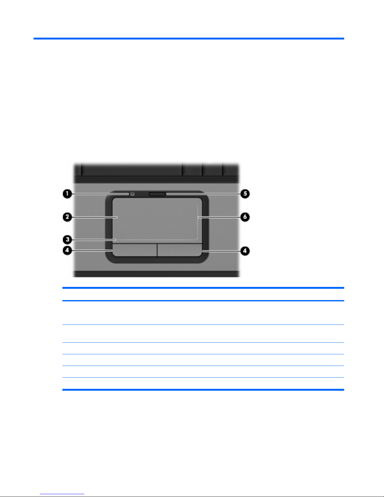
Pointing devices
Item Component Function
(1) TouchPad light
●
Blue: TouchPad is enabled.
●
Amber: TouchPad is disabled.
(2) TouchPad Moves the pointer and selects or activates items on the
screen.
(3) TouchPad horizontal scroll zone Allows you to scroll left or right.
(4) Left and right TouchPad buttons Function like the left and right buttons on an external mouse.
(5) TouchPad on/off button Enables/disables the TouchPad.
(6) TouchPad vertical scroll zone Allows you to scroll up or down.
4Chapter 2 External component identification
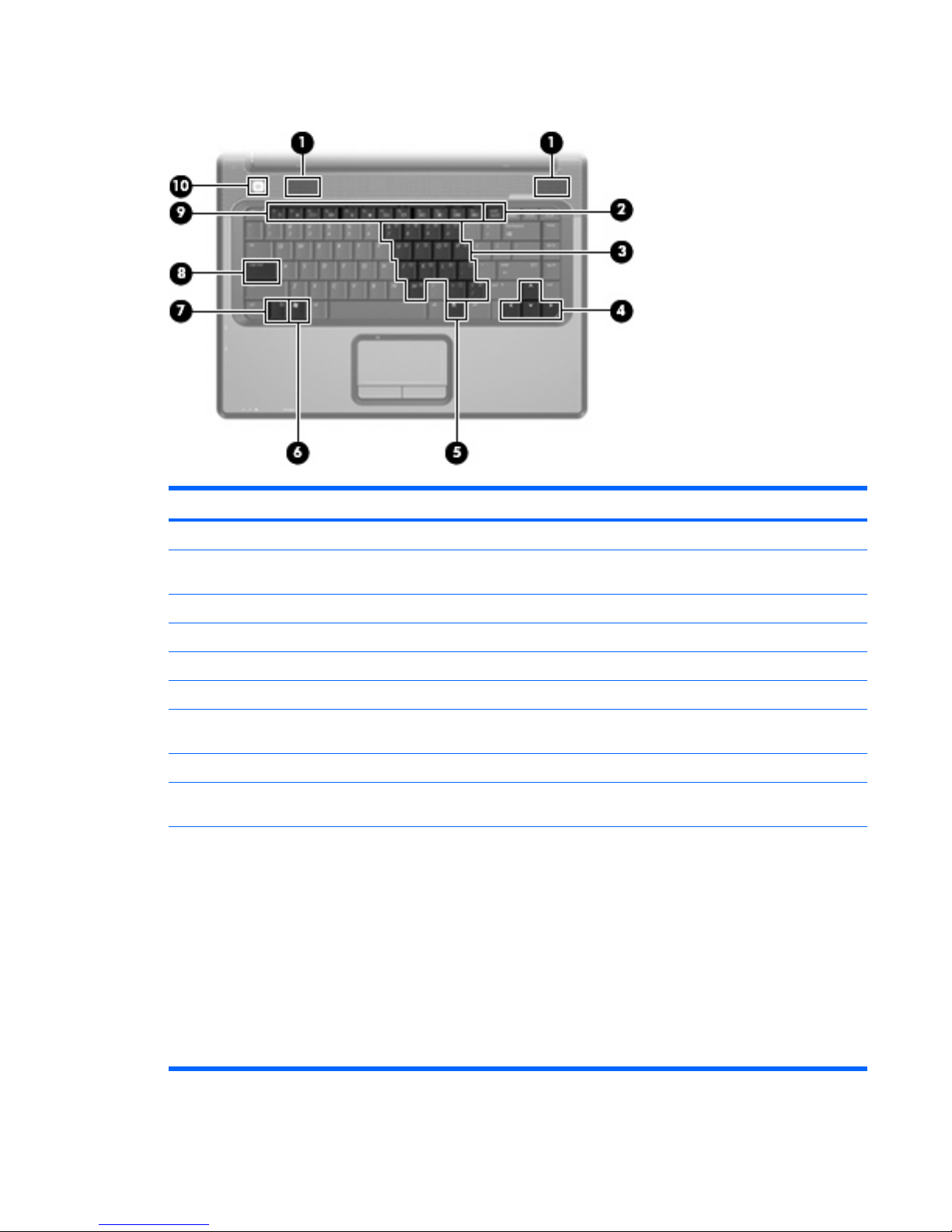
Keys
Item Component Function
(1) Speakers Produce sound.
(2) num lock key Enables numeric lock, turns on the embedded numeric
keypad, and turns on the num lock light.
(3) Embedded numeric keypad keys Can be used like the keys on an external numeric keypad.
(4) Arrow keys Move the cursor around the screen.
(5) Windows applications key Displays a shortcut menu for items beneath the pointer.
(6) Windows logo key Displays the Windows® Start menu.
(7) fn key Executes frequently used system functions when pressed in
combination with a function key or the esc key.
(8) caps lock key Enables caps lock and turns on the caps lock light.
(9) Function keys Execute frequently used system functions when pressed in
combination with the fn key.
(10) Power button
●
When the computer is off, press the button to turn on
the computer.
●
When the computer is on, press the button to initiate
Hibernation.
●
When the computer is in the Sleep state, briefly press
the button to exit Hibernation.
●
When the computer is in Hibernation, briefly press the
button to exit Hibernation.
If the computer has stopped responding and Windows
shutdown procedures cannot be used, press and hold the
power button for at least 5 seconds to turn off the computer.
Top components 5

Front components
Item Component Function
(1) Power light
●
On: The computer is on.
●
Blinking: The computer is in the Sleep state.
●
Off: The computer is off or in Hibernation.
(2) Battery light
●
On: A battery is charging.
●
Blinking: A battery that is the only available power
source has reached a low battery level. When the
battery reaches a critical low battery level, the battery
light begins blinking rapidly.
●
Off: If the computer is plugged into an external power
source, the light is turned off when all batteries in the
computer are fully charged. If the computer is not
plugged into an external power source, the light stays
off until the battery reaches a low battery level.
(3) Drive light Blinks when the hard drive or optical drive is being
accessed.
(4) Wireless switch Turns the wireless feature on or off, but does not create a
wireless connection.
NOTE: A wireless network must be set up in
order to establish a wireless connection.
(5) Wireless light
●
Blue: An integrated wireless device, such as a wireless
local area network (LAN) device and/or a Bluetooth®
device, is turned on.
●
Amber: All wireless devices are turned off.
(6) Audio-in (microphone) jack Connects an optional computer headset microphone, stereo
array microphone, or monaural microphone.
(7) Audio-out (headphone) jack Produces sound when connected to optional powered stereo
speakers, headphones, ear buds, a headset, or television
audio.
*This table describes factory settings. For information about changing factory settings, refer to the user guides located in Help
and Support.
6Chapter 2 External component identification
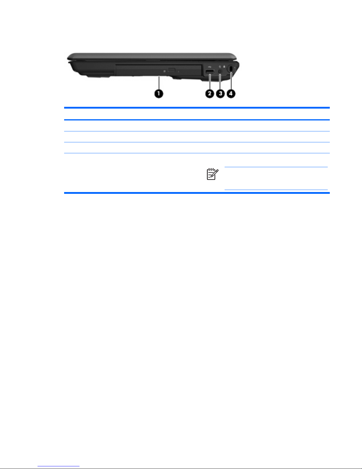
Right-side components
Item Component Function
(1) Optical drive Reads an optical disc.
(2) USB port (select models only) Connects an optional USB device.
(3) Power connector Connects an AC adapter.
(4) Security cable slot Attaches an optional security cable to the computer.
NOTE: The security cable is designed to act as a
deterrent, but it may not prevent the computer from
being mishandled or stolen.
Right-side components 7
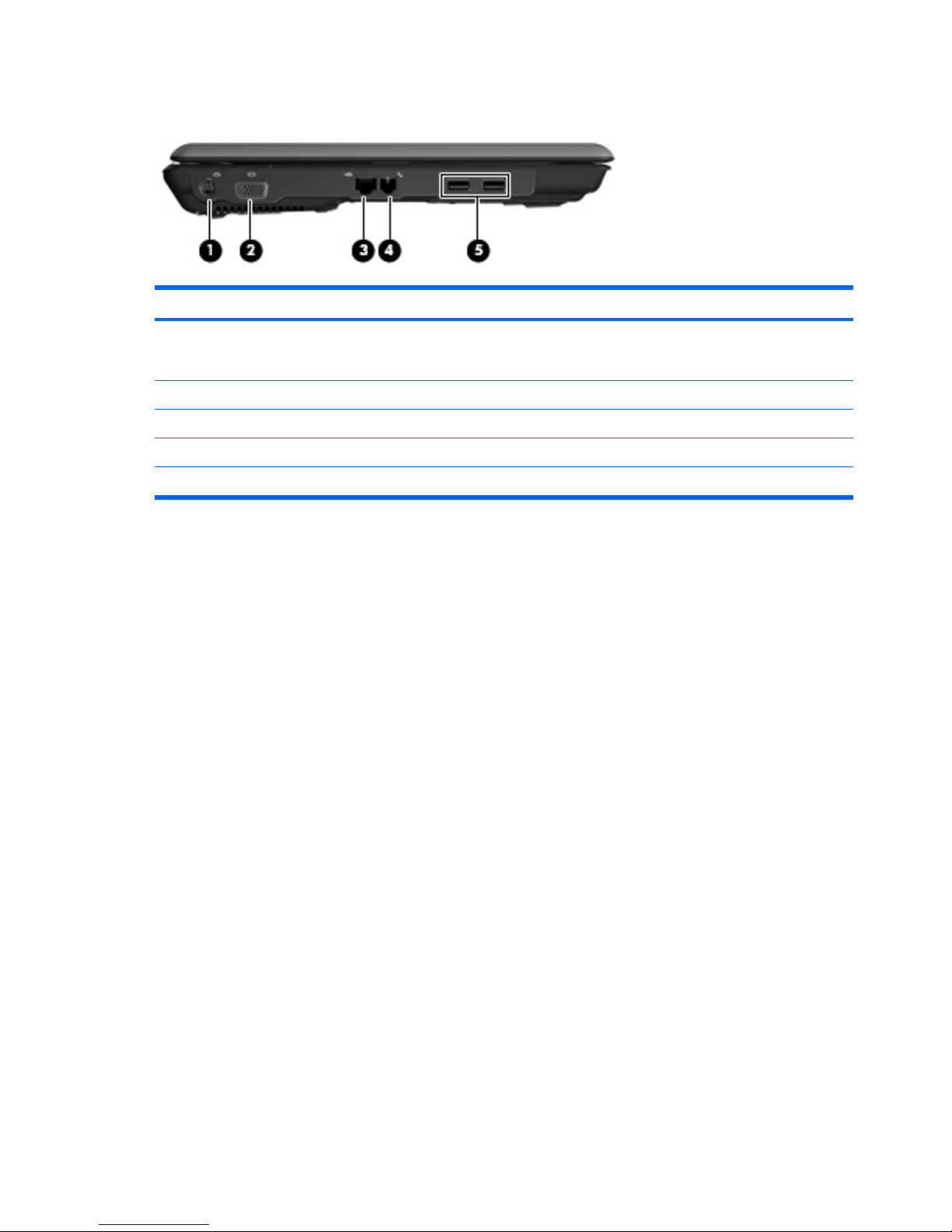
Left-side components
Item Component Function
(1) S-Video-out jack Connects an optional S-Video device, such as a television,
VCR, camcorder, overhead projector, or video capture
card.
(2) External monitor port Connects an external VGA monitor or projector.
(3) RJ-45 (network) jack Connects a network cable.
(4) RJ-11 (modem) jack Connects a modem cable.
(5) USB ports (select models only) Connect optional USB devices.
8Chapter 2 External component identification
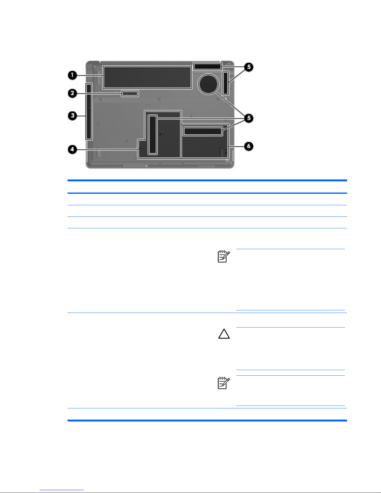
Bottom components
Item Component Function
(1) Battery bay Holds the battery.
(2) Battery release latch Releases the battery from the battery bay.
(3) Optical drive Reads an optical disc.
(4) Memory module compartment Contains the memory module slots, the WLAN module slot,
and the RTC battery.
NOTE: To prevent an unresponsive system and
the display of a warning message, replace with
only a WLAN device authorized for use in the
computer by the governmental agency that
regulates wireless devices in your country or
region. If you replace the device and then receive
a warning message, remove the device to restore
computer functionality. Then contact Customer
Care through Help and Support.
(5) Vents (5) Enable airflow to cool internal components.
CAUTION: To prevent overheating, do not
obstruct vents. Use the computer only on a hard, flat
surface. Do not allow another hard surface, such as
an adjoining optional printer, or a soft surface,
such as pillows or thick rugs or clothing, to block
airflow.
NOTE: The computer fan starts up automatically
to cool internal components and prevent
overheating. It is normal for the internal fan to cycle
on and off during routine operation.
(6) Hard drive bay Holds the hard drive.
Bottom components 9

3
Unknown user password
If the computer you are servicing has an unknown user password, follow these steps to clear the password.
NOTE: These steps also clear CMOS.
1. Shut down the computer. If you are unsure whether the computer is off or in Hibernation, turn the
computer on, and then shut it down through the operating system.
2. Disconnect all external devices connected to the computer.
3. Disconnect the power cord.
4. Remove the battery (see
Battery on page 28).
5. Remove the real-time clock (RTC) battery (see
RTC battery on page 33).
6. Wait approximately 5 minutes.
7. Replace the RTC battery and reassemble the computer.
8. Connect AC power to the computer. Do not reinsert any batteries at this time.
9. Turn on the computer.
All passwords and all CMOS settings have been cleared.
10 Chapter 3 Unknown user password
4
Illustrated parts catalog
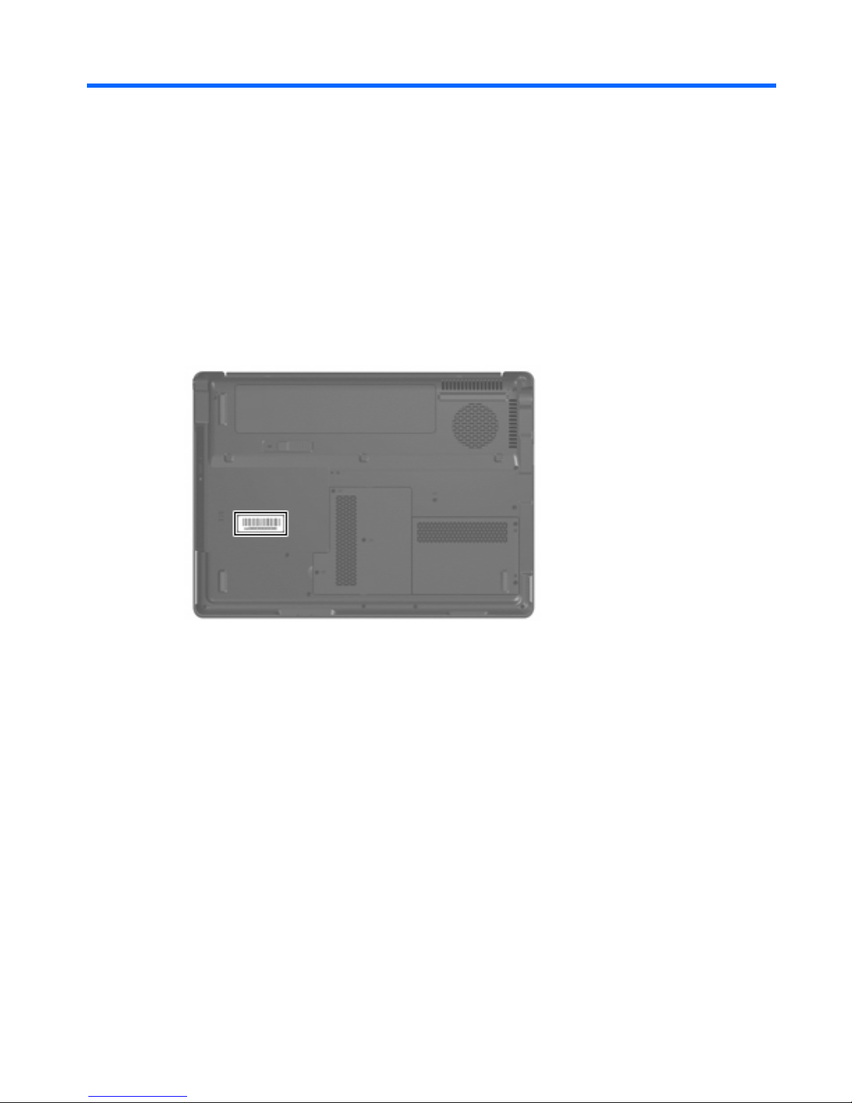
Serial number location
When ordering parts or requesting information, provide the computer serial number and model number
located on the bottom of the computer.
Serial number location 11
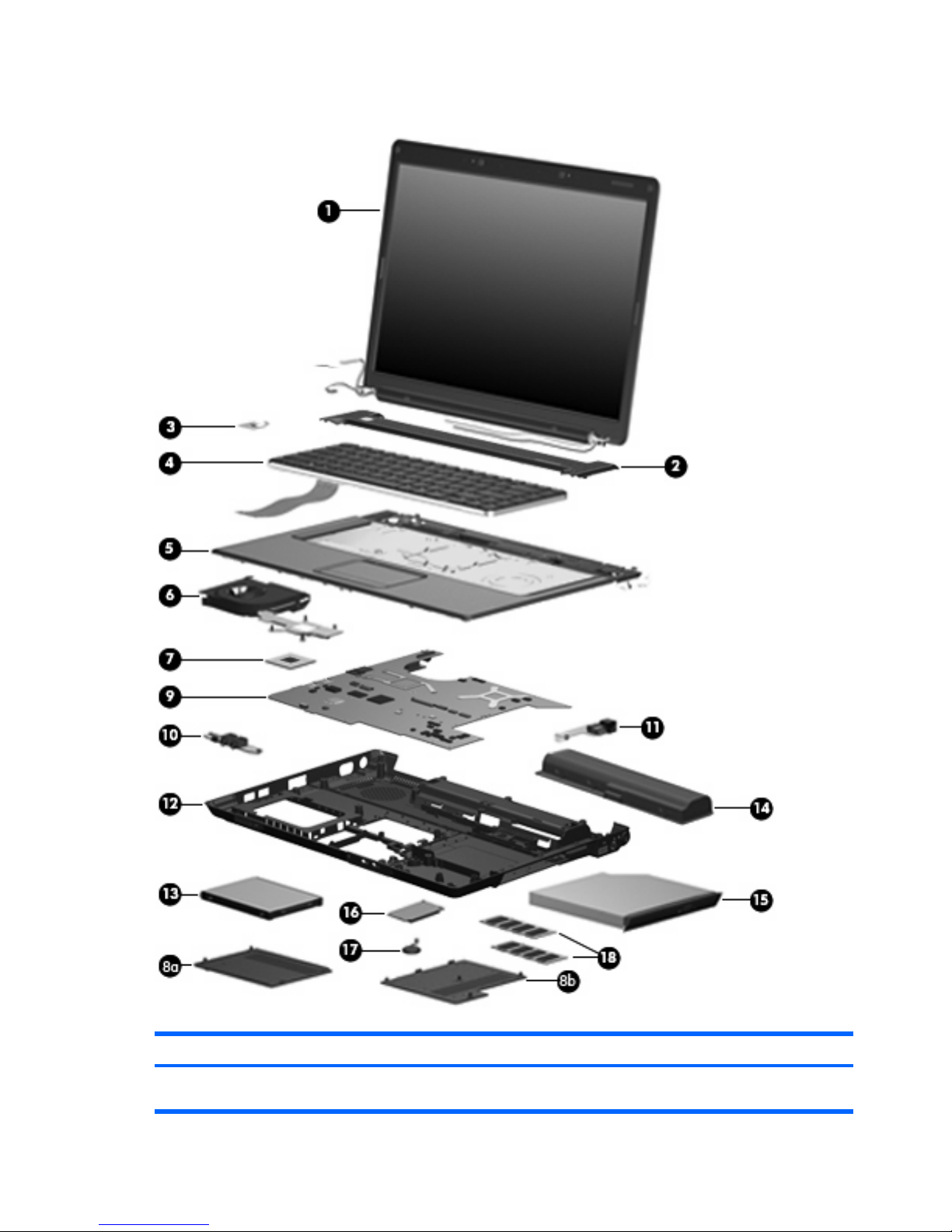
Computer major components
Item Description Spare part number
(1) 15.4-inch, WXGA, BrightView display assembly (includes display panel cable
and wireless antenna transceivers and cables)
442876-001
12 Chapter 4 Illustrated parts catalog

Item Description Spare part number
(2) Switch cover (includes LED board and LED board cable) 442889-001
(3) Power button board (includes power button board and cable) 443153-001
(4) Keyboards
Denmark, Norway, and Sweden 442887-DH1
France 442887-051
French Canada 442887-121
International 442887-B31
Italy 442887-061
Korea 442887-AD1
Latin America 442887-161
Saudi Arabia 442887-171
Spain
442887-071
Taiwan 442887-AB1
Thailand 442887-281
The United Kingdom 442887-031
The United States 442887-001
(5) Top cover (includes speakers, TouchPad, and TouchPad cable) 442888-001
(6) Fan/heat sink assembly (includes thermal pads) 431450-001
(7) Processors (include thermal pad)
AMD Turion TL-52 (1.6-GHz, 1-MB L2 cache) 431372-001
AMD Turion TL-50 (1.6-GHz, 512-KB L2 cache) 431371-001
AMD Turion MK-36 (2.0-GHz, 512-KB L2 cache) 437803-001
Mobile AMD Sempron 3500+ (1.8-GHz, 1-MB L2 cache) 434414-001
Mobile AMD Sempron 3400+ (1.8-GHz, 512-KB L2 cache) 431375-001
Plastics Kit 442891-001
(8a) Hard drive cover (includes one rubber foot and 2 captive screws, secured by C-clips)
(8b) Memory module compartment cover (includes 3 captive screws, secured by C-clips)
(9) System board
(10) Audio board 431444-001
(11) USB/power connector board (includes USB/power connector board cable) 431445-001
(12) Base enclosure (include wireless switch and 4 rubber feet, not illustrated) 442890-001
Rubber Feet Kit (includes computer feet, not illustrated) 431431-001
(13) Hard drives (all 5400-rpm, include hard drive bracket and hard drive connector)
120-GB 442882-001
Computer major components 13

Item Description Spare part number
100-GB 444003-001
80-GB 442881-001
(14) 6-cell, 2.20-Ah battery 441425-001
(15) Optical drives (include bezel)
DVD±RW and CD-RW Super Multi Double-Layer Combo Drive 442883-001
DVD-RW and CD-RW Combo Drive 442884-001
(16) WLAN modules
802.11a/b/g WLAN module for use in Canada and the United States. 407160-001
802.11a/b/g WLAN module for use in China, Ecuador, Haiti, Honduras, Pakistan,
Peru, Qatar, South Korea, Uruguay, and Venezuela.
407160-002
802.11b/g WLAN module for use in Argentina, Brazil, Canada, Chile, Mexico,
Taiwan, and the United States.
407159-001
802.11b/g WLAN module for use in China, Ecuador, Haiti, Honduras, Pakistan, Peru,
Qatar, South Korea, Uruguay, and Venezuela.
407159-002
(17) RTC battery (includes 2-sided tape) 431436-001
(18) Memory modules
1024-MB (PC2-4200, 533-MHz, 1-DIMM) 443489-001
512-MB (PC2-5300, 667-MHz, 1-DIMM) 442879-001
Cable Kit (not illustrated)
14 Chapter 4 Illustrated parts catalog
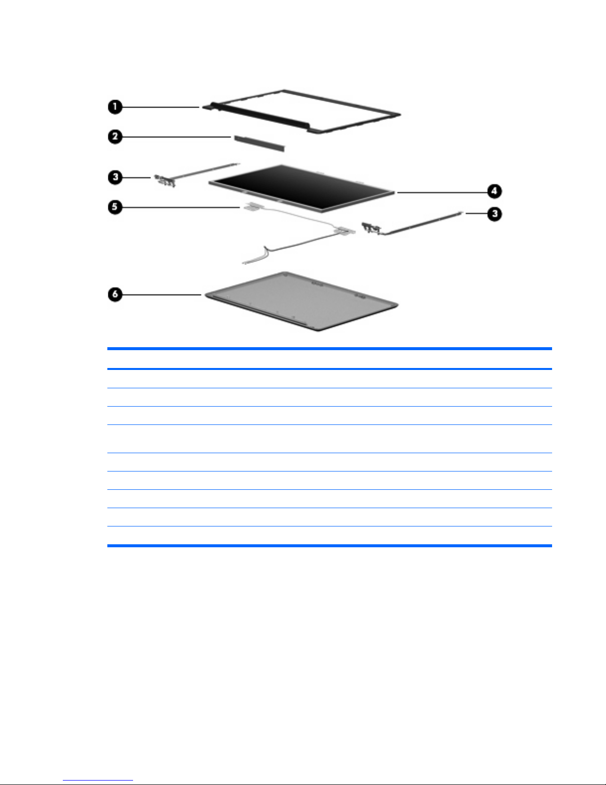
Display assembly components
Item Description Spare part number
(1) Display bezel 433284-001
(2) Display inverter (includes Mylar shield) 431391-001
(3) Display Hinge Kit 433288-001
(4) 15.4-inch, WXGA, BrightView display panel (includes display panel cable and
wireless antenna transceivers and cables)
442887-001
(5) Wireless Antenna Kit (includes wireless antenna transceivers and cables) 431398-001
(6) Display enclosure (includes wireless antenna transceivers and cables) 442878-001
Display Cable Kit (not illustrated) 433287-001
Display Logo Kit (not illustrated) 442892-001
Display Screw Kit (not illustrated) 431400-001
Display assembly components 15
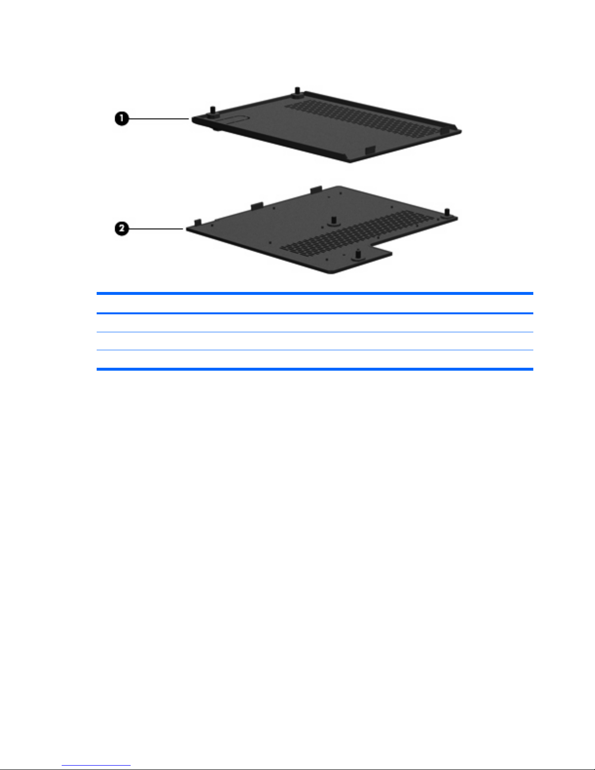
Plastics Kit
Item Description Spare part number
Plastics Kit 442891-001
(1) Hard drive cover (includes 2 captive screws, secured by C-clips)
(2) Memory module compartment cover (includes 2 captive screws, secured by C-clips)
16 Chapter 4 Illustrated parts catalog
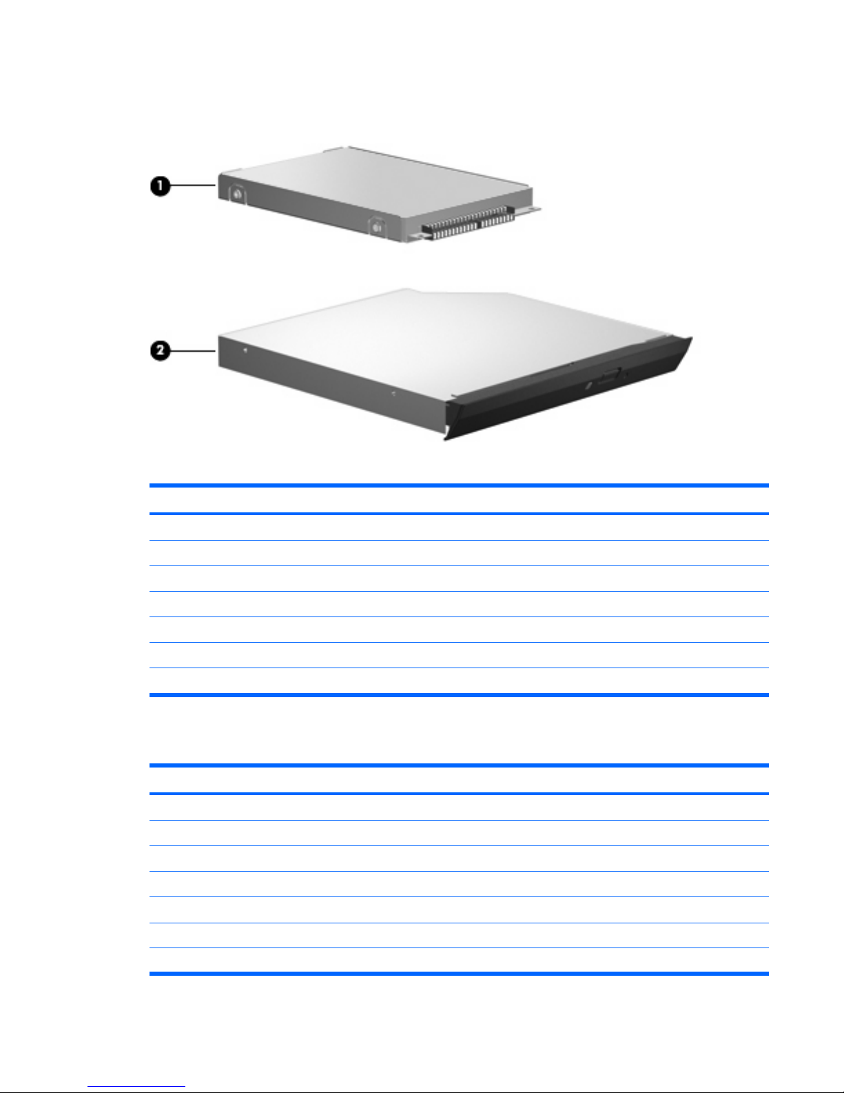
Mass storage devices
Item Description Spare part number
(1) Hard drives (all 5400-rpm, include frame and hard drive connector)
120-GB 442882-001
100-GB 444003-001
80-GB 442881-001
(2) Optical drives (include bezel and bracket)
DVD±RW and CD-RW Super Multi Double-Layer Combo Drive 442884-001
DVD-RW and CD-RW Combo Drive 442883-001
Miscellaneous parts
Description Spare part number
65-watt AC adapter 402018-001
Analog TV tuner 407941-001
Backpack 405527-001
Carrying case 418162-001
Composite S-Video and audio input cable 407939-001
Headset 371693-001
HP Remote Control 407313-001
Mass storage devices 17

Description Spare part number
HP Remote Control II Plus 435743-001
RF cable 408485-001
RF input adapter cable 407940-001
TV tuner remote control 408479-001
USB infrared emitter 408483-001
USB travel mouse 309674-001
Wired optical mouse 436238-001
Power cords:
Australia 394279-011
Canada, French Canada, Latin America, Thailand, and the United States 394279-001
Denmark 394279-081
Belgium, Europe, Finland, France, Germany, Greece, the Netherlands, Norway, Portugal,
Spain, and Sweden
394279-021
India 394279-D61
Italy 394279-061
Korea 394279-AD1
Taiwan 394279-AB1
The United Kingdom 394279-031
Screw Kit (includes the screws listed below)
●
Phillips PM3.0×3.0 screw
●
Phillips PM2.5×10.0 screw
●
Phillips PM2.5×7.0 screw
●
Phillips PM2.5×5.0 screw
●
Phillips PM2.5×4.0 screw
●
Phillips PM2.0×6.0 screw
●
Phillips PM2.0×5.0 captive screw
●
Phillips PM2.0×4.0 screw
●
Phillips PM2.0×3.0 screw
431433-001
18 Chapter 4 Illustrated parts catalog

Sequential part number listing
Spare part number Description
309674-001 USB travel mouse
364727-001 USB digital drive
371693-001 Wired headset with volume control
394279-001 Power cord for use in Canada, French Canada, Latin America, Thailand, and the United States
394279-011 Power cord for use in Australia
394279-021 Power cord for use in Belgium, Europe, Finland, France, Germany, Greece, the Netherlands,
Norway, Portugal, Spain, and Sweden
394279-031 Power cord for use in the United Kingdom
394279-061 Power cord for use in Italy
394279-081 Power cord for use in Denmark
394279-AB1 Power cord for use in Taiwan
394279-AD1 Power cord for use in Korea
394279-D61 Power cord for use in India
402018-001 65-watt AC adapter
405527-001 Backpack
407159-001 802.11b/g WLAN module for use in the MOW countries or regions listed below:
Argentina, Brazil, Canada, Chile, Mexico, Taiwan, the United States
407159-002 802.11b/g WLAN module for use in the ROW countries or regions listed below:
China, Ecuador, Haiti, Honduras, Pakistan, Peru, Qatar, South Korea, Uruguay, Venezuela
407160-001 802.11a/b/g WLAN module for use in Canada and the United States
407160-002 802.11a/b/g WLAN module for use in the ROW countries or regions listed below:
China, Ecuador, Haiti, Honduras, Pakistan, Peru, Qatar, South Korea, Uruguay, Venezuela
407313-001 HP Remote Control
407939-001 Composite S-Video and audio input cable
407940-001 RF input adapter cable
407941-001 Analog TV tuner
408479-001 TV tuner remote control
408483-001 USB infrared emitter
408485-001 RF cable
418162-001 HP carrying case
431371-001 AMD Turion TL-50 processor (1.6-GHz, 1-MB L2 cache)
431372-001 AMD Turion TL-52 processor (1.6-GHz, 1-MB L2 cache)
431375-001 Mobile AMD Sempron 3400+ processor (1.8-GHz, 512-KB L2 cache)
Sequential part number listing 19

Spare part number Description
431391-001 Display inverter
431398-001 Wireless Antenna Kit
431400-001 Display Screw Kit
431431-001 Rubber Feet Kit (includes computer feet)
431433-001 Screw Kit
431436-001 RTC battery (includes 2-sided tape)
431444-001 Audio board (includes audio board cable)
431445-001 USB/power connector board (includes USB/power connector board cable)
431450-001 Fan/heat sink assembly (includes thermal pads)
433284-001 Display bezel
433287-001 Display Cable Kit
433288-001 Display Hinge Kit
434414-001 Mobile AMD Sempron 3500+ processor (1.8-GHz, 1-MB L2 cache)
435743-001 HP Remote Control II Plus
437803-001 AMD Turion MK-36 processor (2.0-GHz, 512-KB L2 cache)
441425-001 6-cell, 2.20-Ah battery
442875-001 System board
442876-001 15.4-inch, WXGA, BrightView, display assembly (includes wireless antenna transceivers and
cables)
442877-001 15.4-inch, WXGA, BrightView, display panel
442878-001 Display enclosure (includes wireless antenna transceivers and cables)
442879-001 512-GB memory module (PC2-5300, 667-GHz, 1 DIMM)
442881-001 80-GB, 5400-rpm hard drive
442882-001 120-GB, 5400-rpm hard drive
442883-001 DVD-RW and CD-RW Combo Drive
442884-001 DVD±RW and CD-RW Super Multi Double-Layer Combo Drive
442887-001 Keyboard for use in the United States
442887-031 Windows Vista keyboard for use in the United Kingdom
442887-051 Windows Vista keyboard for use in France
442887-061 Windows Vista keyboard for use in Italy
442887-071 Windows Vista keyboard for use in Spain
442887-121 Windows Vista keyboard for use in French Canada
442887-161 Windows Vista keyboard for use in Latin America
442887-171 Windows Vista keyboard for use in Saudi Arabia
442887-281 Windows Vista keyboard for use in Thailand
20 Chapter 4 Illustrated parts catalog

Spare part number Description
442887-AB1 Windows Vista keyboard for use in Taiwan
442887-AD1 Windows Vista keyboard for use in Korea
442887-B31 Windows Vista keyboard for international use
442887-DH1 Windows Vista keyboard for use in Denmark, Norway, and Sweden
442888-001 Top cover (includes speakers and TouchPad)
442889-001 Switch cover (includes LED board and LED board cable)
442890-001 Base enclosure (includes wireless switch and 4 computer feet)
442891-001 Plastics Kit
442892-001 Logo Kit
443153-001 Power button board (includes power button board cable)
443489-001 1024-MB memory module (PC2-4200, 533-MHz, 1 DIMM)
444003-001 100-GB, 5400-rpm hard drive
Sequential part number listing 21

5
Removal and replacement
procedures
Preliminary replacement requirements
Tools required
You will need the following tools to complete the removal and replacement procedures:
●
Flat-bladed screwdriver
●
Hex 5.0-mm nutdriver
●
Magnetic screwdriver
●
Phillips P0 and P1 screwdrivers
Service considerations
The following sections include some of the considerations that you should keep in mind during disassembly
and assembly procedures.
NOTE: As you remove each subassembly from the computer, place the subassembly (and all
accompanying screws) away from the work area to prevent damage.
Plastic parts
Using excessive force during disassembly and reassembly can damage plastic parts. Use care when
handling the plastic parts. Apply pressure only at the points designated in the maintenance instructions.
22 Chapter 5 Removal and replacement procedures

Cables and connectors
CAUTION: When servicing the computer, be sure that cables are placed in their proper
locations during the reassembly process. Improper cable placement can damage the computer.
Cables must be handled with extreme care to avoid damage. Apply only the tension required to unseat
or seat the cables during removal and insertion. Handle cables by the connector whenever possible. In
all cases, avoid bending, twisting, or tearing cables. Be sure that cables are routed in such a way that
they cannot be caught or snagged by parts being removed or replaced. Handle flex cables with extreme
care; these cables tear easily.
Drive handling
CAUTION: Drives are fragile components that must be handled with care. To prevent damage
to the computer, damage to a drive, or loss of information, observe these precautions:
Before removing or inserting a hard drive, shut down the computer. If you are unsure whether the
computer is off or in Hibernation, turn the computer on, and then shut it down through the operating
system.
Before handling a drive, be sure that you are discharged of static electricity. While handling a
drive, avoid touching the connector.
Before removing a diskette drive or optical drive, be sure that a diskette or disc is not in the drive
and be sure that the optical drive tray is closed.
Handle drives on surfaces covered with at least one inch of shock-proof foam.
Avoid dropping drives from any height onto any surface.
After removing a hard drive, an optical drive, or a diskette drive, place it in a static-proof bag.
Avoid exposing a hard drive to products that have magnetic fields, such as monitors or speakers.
Avoid exposing a drive to temperature extremes or liquids.
If a drive must be mailed, place the drive in a bubble pack mailer or other suitable form of protective
packaging and label the package “FRAGILE.”
Preliminary replacement requirements 23

Grounding guidelines
Electrostatic discharge damage
Electronic components are sensitive to electrostatic discharge (ESD). Circuitry design and structure
determine the degree of sensitivity. Networks built into many integrated circuits provide some protection,
but in many cases, ESD contains enough power to alter device parameters or melt silicon junctions.
A discharge of static electricity from a finger or other conductor can destroy static-sensitive devices or
microcircuitry. Even if the spark is neither felt nor heard, damage may have occurred.
An electronic device exposed to ESD may not be affected at all and can work perfectly throughout a
normal cycle. Or the device may function normally for a while, then degrade in the internal layers,
reducing its life expectancy.
CAUTION: To prevent damage to the computer when you are removing or installing internal
components, observe these precautions:
Keep components in their electrostatic-safe containers until you area ready to install them.
Use nonmagnetic tools.
Before touching an electronic component, discharge static electricity by using the guidelines
described in this section.
Avoid touching pins, leads, and circuitry. Handle electronic components as little as possible.
If you remove a component, place it in an electrostatic-safe container.
The following table shows how humidity affects the electrostatic voltage levels generated by different
activities.
CAUTION: A product can be degraded by as little as 700 V.
Typical electrostatic voltage levels
Relative humidity
Event 10% 40% 55%
Walking across carpet 35,000 V 15,000 V 7,500 V
Walking across vinyl floor 12,000 V 5,000 V 3,000 V
Motions of bench worker 6,000 v 800 V 400 V
Removing DIPS from plastic tube 2,000 V 700 V 400 V
Removing DIPS from vinyl tray 11,500 V 4,000 V 2,000 V
Removing DIPS from Styrofoam 14,500 V 5,000 V 3,500 V
Removing bubble pack from PCB 26,500 V 20,000 V 7,000 V
Packing PCBs in foam-lined box 21,000 V 11,000 V 5,000 V
24 Chapter 5 Removal and replacement procedures
 Loading...