

HP Presario 5800 Maintenance & Service Manual
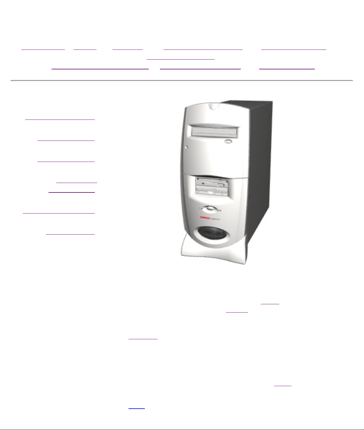
Maintenance & Service Guide
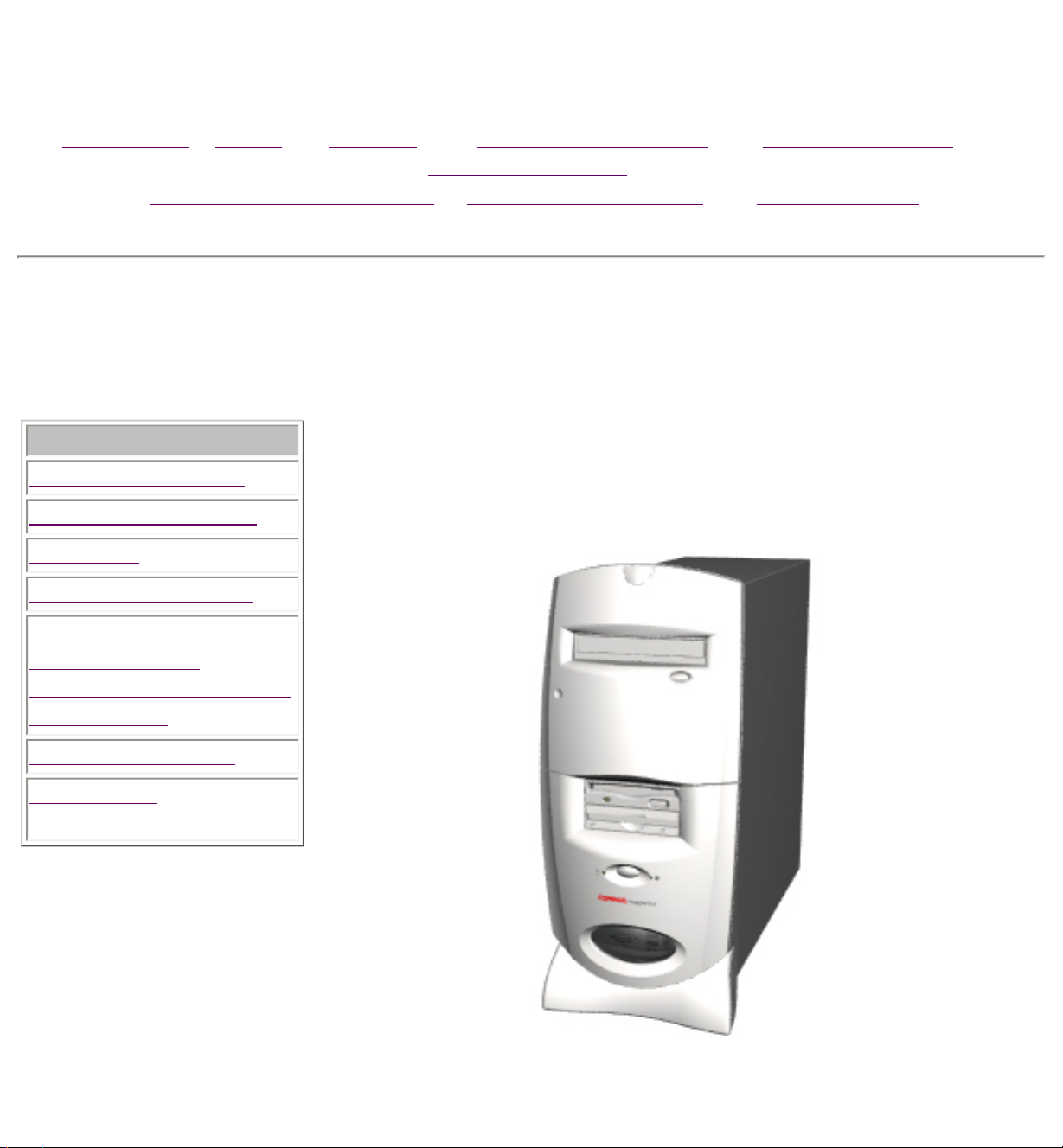
Presario 5800 Series Personal Computers
MSG Index | Home | Preface | Product Description | Troubleshooting |
Illustrated Parts
Removal & Replacement | Jumpers & Switches | Specifications
Product Description
Troubleshooting
Illustrated Parts
Removal &
Replacement
Jumpers & Switches
Specifications
Welcome to the Presario 5800 Series Maintenance and Service
Guide. This online guide is designed to serve the needs of those whose job
it is to repair Compaq products. Many of the components of the hardcopy
MSG are contained in this online guide. The
and trademark information. The Preface shows symbol conventions,
Technician Notes and Serial Number locations on the unit.
Download a ZIP file of the complete MSG to local hard drive.
This MSG will be periodically maintained and updated as needed.
To report a technical problem, contact your Regional Support Center or IM
Help Center.
Notice contains the copyright
For content comments or questions, contact the Editor.
Top
Maintenance & Service Guide
Presario 5800 Series Personal Computers
MSG Index | Home | Preface | Product Description | Troubleshooting |
Illustrated Parts
Removal & Replacement | Jumpers & Switches | Specifications
Symbols
The following words and symbols mark special messages throughout this guide.
WARNING: Text set off in this manner indicates that failure to follow directions in
the warning could result in bodily harm or loss of life
.
CAUTION: Text set off in this manner indicates that failure to follow directions in the
caution could result in damage to equipment or loss of data.
IMPORTANT:
NOTE:
Technician Notes
WARNING: Only authorized technicians trained by Compaq should repair this
equipment. All troubleshooting and repair procedures are detailed to allow only
subassembly/module level repair. Because of the complexity of the individual boards
and subassemblies, the user should not attempt to make repairs at the component
level or to make modifications to any printed circuit board. Improper repairs can
create a safety hazard. Any indications of component replacement or printed circuit
board modifications may void any warranty.
Text set off in this manner presents clarifying information or
specific instructions.
Text set off in this manner presents commentary, sidelights,
or interesting points of information.
Serial Number
When requesting information or ordering spare parts, the computer serial number should be
provided to Compaq. The serial number can be found on the back of the computer next to the fan
grill and on the front bezel behind the drive access door.
Locating Additional Information
The following documentation is available to support this product:
● Compaq Presario documentation set
● Introducing Windows 95 Guide
● Service Training Guides
● Compaq Service Advisories and Bulletins
● Compaq QuickFind
● Compaq Service Quick Reference Guide
● Compaq Help Center
Maintenance & Service Guide
Presario 5800 Series Personal Computers
MSG Index | Home | Preface | Product Description | Troubleshooting |
Illustrated Parts
Removal & Replacement | Jumpers & Switches | Specifications
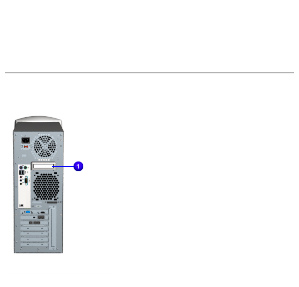
Serial Number
The computer serial number should
be provided to Compaq whenever
requesting information or ordering
spare parts. The serial number is
located on the back 1 and on the
front of the computer, behind the
drive cover (not shown).
Model may vary slightly from the
one shown.
Back to Removal and Replacement
Maintenance & Service Guide
Presario 5800 Series Personal Computers
MSG Index | Home | Preface | Product Description | Troubleshooting | Illustrated Parts
Removal & Replacement | Jumpers & Switches | Specifications
Removal and Replacement
This chapter provides general service information for Compaq Presario 5800
Series Personal Computers. Adherence to the procedures and precautions
Removal Sequence
described in this chapter is essential for proper service.
Preparation for Disassembly
Serial Number Location
Chassis
Mass Storage Devices
Button Board
Front I/O Cable
Digital Creativity Imaging Center
Option Card Retainer
Graphics Board
PCI Cards
Memory
Processor
Processor Retention Clips
The topics discussed in this section include the following:
● Electrostatic Discharge
● Generating Static
● Preventing Electrostatic Damage to Equipment
● Preventing Damage to Drives
● Grounding Methods
● Grounding Workstations
● Grounding Equipment
● Recommended Materials and Equipment
● Tool Requirements
● Screws
● Cables and Connectors
Electrostatic Discharge
A sudden discharge of static electricity from a finger or other conductor can
destroy static-sensitive devices or microcircuitry. Often the spark is neither felt
nor heard, but damage occurs. An electronic device exposed to electrostatic
discharge (ESD) may not be affected at all and will work perfectly throughout a
normal cycle. Or it may function normally for a while, then degrade in the internal
layers, reducing its life expectancy.
RTC Battery
System Board Cables
System Board
Parallel Port
Back I/O Panel
Power Supply
Networks built into many integrated circuits provide some protection, but in many
cases, the discharge contains enough power to alter device parameters or melt
silicon junctions.
Top
Generating Static
The accompanying table shows typical electrostatic voltages generated by
different activities.
Typical Electrostatic Voltages
Relative Humidity
Event 10% 40% 55%
Walking across carpet 35,000 V 15,000 V 7,500 V
Walking across vinyl floor 12,000 V 5,000 V 3,000 V
Motions of bench worker 6,000 V 800 V 400 V
Removing DIPS from plastic tubes 2,000 V 700 V 400 V
Removing DIPS from vinyl trays 11,500 V 4,000 V 2,000 V
Removing DIPS from Styrofoam 14,500 V 5,000 V 3,500 V
Removing bubble pack from PCBs 26,000 V 20,000 V 7,000 V
Packing PCBs in foam-lined box 21,000 V 11,000 V 5,000 V
NOTE: 700 volts can degrade a product.
Top
Preventing Electrostatic Damage to Equipment
Many electronic components are sensitive to ESD. Circuitry design and structure
determine the degree of sensitivity. The following proper packaging and
grounding precautions are necessary to prevent damage:
● Protect all electrostatic parts and assemblies with conductive or approved
containers or packaging.
● Keep electrostatic sensitive parts in their containers until they arrive at
static-free stations.
● Place items on a grounded surface before removing them from their
container.
● Always be properly grounded when touching a sensitive component or
assembly.
● Place reusable electronic-sensitive parts from assemblies in protective
packaging or conductive foam.
● Use transporters and conveyors made of antistatic belts and metal roller
bushings. Mechanized equipment used for moving materials must be wired
to ground and proper materials selected to avoid static charging. When
grounding is not possible, use an ionizer to dissipate electric charges.
The accompanying table shows typical static-shielding protection levels afforded
by different protective packaging materials.
Static-Shielding Protection Levels
Method Voltages
Antistatic Plastic 1,500
Carbon-Loaded Plastic 7,500
Metallized Laminate 15,000
Top
Preventing Damage to Drives
To prevent static damage to hard drives, use the following precautions:
● Handle drives gently, using static-guarding techniques.
● Store drives in the original shipping containers.
● Avoid dropping drives from any height onto any surface.
● Handle drives on surfaces that have at least one inch of shock-proof foam.
● Always place drives PCB assembly side down on the foam.
Top
Grounding Methods
The method for grounding must include a wrist strap or a foot strap at a grounded
workstation. When seated, wear a wrist strap connected to a grounded system.
When standing, use footstraps and a grounded floor mat.
Top
Grounding Workstations
To prevent static damage at the workstation, use the following precautions:
● Cover the workstation with approved static-dissipative material.
● Provide a wrist strap connected to the work surface and properly grounded
tools and equipment.
● Use static-dissipative mats, heel straps, or air ionizers to give added
protection.
● Handle electrostatic sensitive components, parts, and assemblies by the
case or PCB laminate. Handle them only at static-free workstations.
● Avoid contact with pins, leads, or circuitry.
● Turn off power and input signals before inserting and removing connectors
or test equipment.
● Use fixtures made of static-safe materials when fixtures must directly
contact dissipative surfaces.
● Keep work area free of nonconductive materials such as ordinary plastic
assembly aids and Styrofoam.
● Use field service tools that are conductive, such as cutters, screwdrivers,
vacuums.
● Use a portable field service kit with a static-dissipative vinyl pouch that
folds out of a work mat. Also use a wrist strap and a ground cord for the
work surface. Ground the cord to the chassis of the equipment undergoing
test or repair.
Top
Grounding Equipment
Use the following equipment to prevent static electricity damage to the
equipment:
● Wrist straps are flexible straps with a minimum of 1 mega ohm ± 10%
resistance to the ground cords. To provide proper ground, a strap must be
worn snug against the skin. On grounded mats without banana-plug
connectors, connect a wrist strap with alligator clips.
● Heelstraps/Toestraps/Bootstraps can be used at standing workstations and
are compatible with most types of boots and shoes. On conductive floors or
dissipative floor mats, use them on both feet with a minimum of 1 mega
ohm resistance between operator and ground. To be effective, the
conductive strips must be worn in contact with the skin.
Top
Recommended Materials and Equipment
Other materials and equipment that are recommended for use in preventing static
electricity include:
● Antistatic tape
● Antistatic smocks, aprons, or sleeve protectors
● Conductive bins, and other assembly or soldering aids
● Conductive foam
● Conductive tabletop workstations with ground cord of 1 mega ohm
of resistance
● Static-dissipative table or floor mats with hard tie to ground
● Field service kits
● Static awareness labels
● Wrist straps and footwear straps providing 1 mega ohm (±10%) resistance
● Material handling packages
● Conductive plastic bags
● Conductive plastic tubes
● Conductive tote boxes
● Metal tote boxes
● Opaque shielding bags
● Transparent metallized shielding bags
● Transparent shielding tubes
Top
Tool Requirements
● Torx T-8, T-10, and T-15 screwdrivers
● Needle-nose pliers
● Flat-blade screwdriver
● Diagnostics software
Top
Screws
The screws used in these products are not interchangeable. If an incorrect screw
is used during the reassembly process, it could cause damage to the unit.
Compaq strongly recommends that all screws removed during the disassembly
process be kept with the part that was removed, then returned to their proper
locations.
IMPORTANT:
●
As each subassembly is removed from the computer, it should be
placed away from the work area to prevent damage
Top
Cables and Connectors
Most cables used throughout the unit are ribbon cables. These cables must be
handled with extreme care to avoid damage.
Apply only the tension required to seat or unseat the cables during insertion or
removal from the connector. Handle cables by the connector whenever possible.
In all cases, avoid bending, twisting, or tearing the cables, and ensure that cables
are placed in such a way that they cannot be caught or snagged by parts being
removed or replaced.
CAUTION: When servicing these computers, ensure that cables are
placed in their proper location during the reassembly process.
Improper cable placement can cause severe damage to the unit.
CD or DVD Drive
Digital Creativity Imaging Center
Diskette Drive
Hard Drive
Zip Drive
Top

Maintenance & Service Guide
Presario 5800 Series Personal Computers
Notice
The information in this guide is subject to change without notice.
COMPAQ COMPUTER CORPORATION SHALL NOT BE LIABLE FOR
TECHNICAL OR EDITORIAL ERRORS OR OMISSIONS CONTAINED
HEREIN, NOR FOR INCIDENTAL OR CONSEQUENTIAL DAMAGES
RESULTING FROM THE FURNISHING, PERFORMANCE, OR USE OF THIS
MATERIAL.
This guide contains information protected by copyright. No part of this
guide may be photocopied or reproduced in any form without prior
written consent from Compaq Computer Corporation.
© 1998 Compaq Computer Corporation.
All rights reserved. Printed in the U.S.A.
Compaq, Presario Registered U. S. Patent and Trademark Office.
Microsoft, MS-DOS, and Windows are registered trademarks of
Microsoft Corporation.
Windows 95 is a trademark of Microsoft Corporation.
Windows 98 is a trademark of Microsoft Corporation.
The software described in this guide is furnished under a license
agreement or nondisclosure agreement. The software may be used or
copied only in accordance with the terms of the agreement.
Product names mentioned herein may be trademarks and/or registered
trademarks of their respective companies.
Maintenance and Service Guide
Compaq Presario 5800 Series
Personal Computers
© 1999 Compaq Computer Corporation
Maintenance & Service Guide
Presario 5800 Series Personal Computers
MSG Index | Home | Preface | Product Description | Troubleshooting |
Illustrated Parts
Removal & Replacement | Jumpers & Switches | Specifications
Product Description
Product Description
Models and Features
CPU Controls & Lights
Keyboards
CPU Back Connectors
Digital Creativity
Imaging Center
(DCIC)/Creativity Action
Center (CAC)
Power Management
Power Cord
Requirements
This section describes the models and features of the Compaq
Presario 5800 Series of personal computers. Use the navigation bar
at left to find specific features.

Maintenance & Service Guide
5822Celeron/50096136xDVDN/AN/AGW
5827Celeron/500961732x CD-RWN/AGW
5832Celeron/50096136xDVDCD-RWN/AGW
5834Celeron/500961732x CD-RWN/AGW
5835Celeron/500961032xCD-RWN/AGW
5831 K7/5006488xDVD N/A16A
5838K7/500128108xDVD CD-RW 16A
5838 K7/500 128 10 8xDVD N/A 16A
5838 K7/500 128 17 8xDVD CD-RW 16A
5858K7/55064 138xDVD N/A16K
5868K7/600128178xDVD N/A16K
Presario 5800 Series Personal Computers
MSG Index | Home | Preface | Product Description | Troubleshooting | Illustrated Parts
Removal & Replacement | Jumpers & Switches | Specifications
Product Description
Models and Features
The following tables list Compaq Presario 5800 Series Personal Computer models
and model-specific features.
NOTE:
U.S.,
Latin
America,
Canada
Europe,
Middle
East,
Africa
Modem codes:
D = 6 Mb Digital DSL/56k V.90
A = 56k
V.90
K = 56k V.90
GW = 56k V.90
Model Processor
MHz
Memory
(MB)
Hard
Drive
(GB)
Primary
Optical
Second
Optical
Video
Memory
(MB)
Modem
Asia
Pacific
Back to Product Description
Maintenance & Service Guide
Presario 5800 Series Personal Computers
MSG Index | Home | Preface | Product Description | Troubleshooting | Illustrated Parts
Removal & Replacement | Jumpers & Switches | Specifications
Product Description
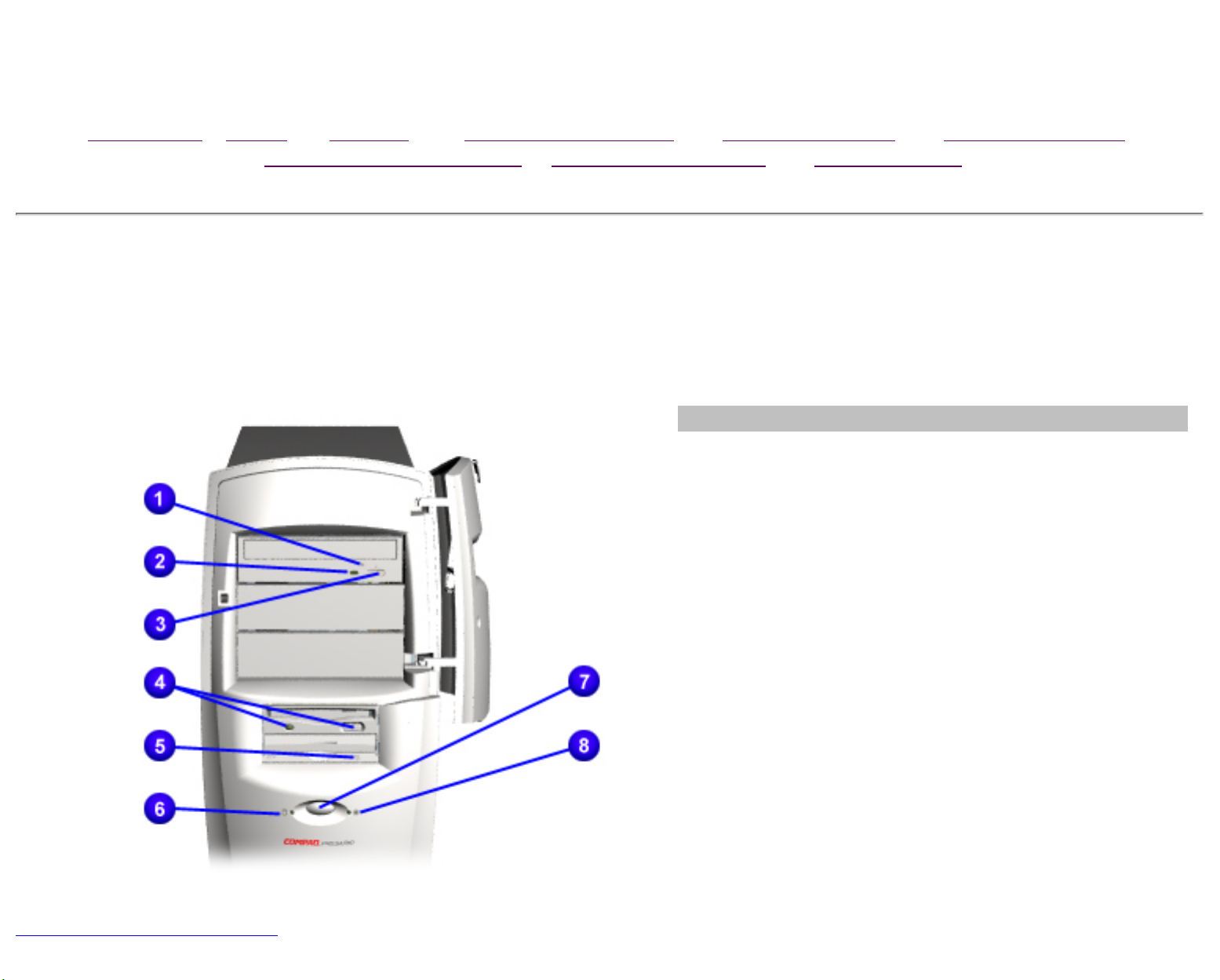
CPU Controls and Lights
Description
1
CD or DVD Manual Eject Button
2
CD or DVD Drive Activity Light
Back to Product Description
3
CD or DVD Load/Ejection Button
4
Diskette Drive Eject Button and Drive Activity
Light
5
Zip Drive Eject Button and Activity Light
6
Hard Drive Activity Light
7
Power Button
8
Power Status Light
Maintenance & Service Guide
Presario 5800 Series Personal Computers
MSG Index | Home | Preface | Product Description | Troubleshooting |
Illustrated Parts
Removal & Replacement | Jumpers & Switches | Specifications
Product Description
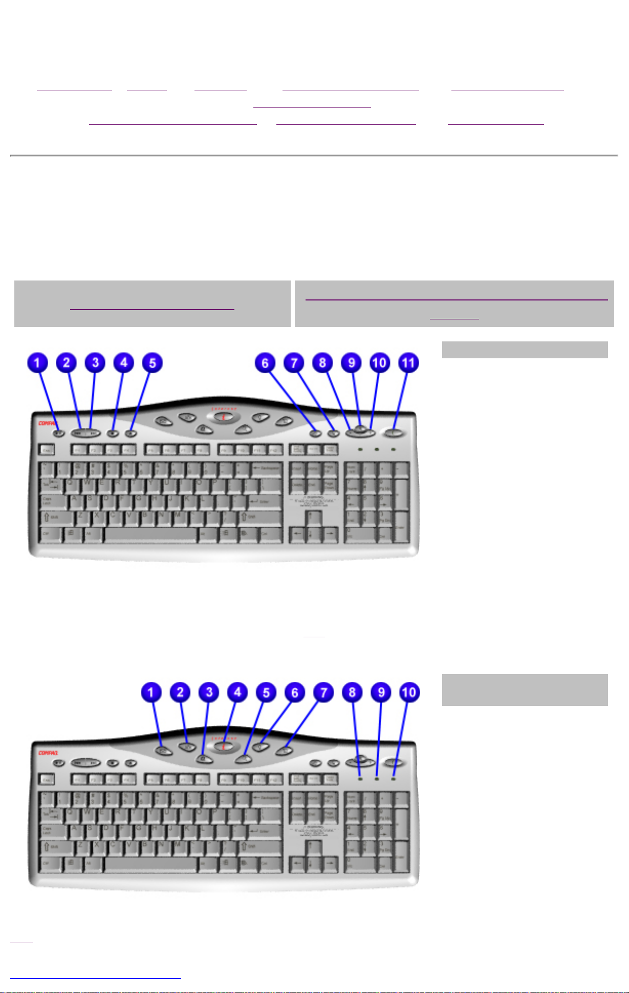
Easy Access Internet Keyboard
Easy Access Buttons
Internet Suite Buttons and Keyboard
Lights
Easy Access Buttons
1
Play/Pause
2
Rewind/Previous track
3
Fast Forward/Next
track
4
Stop
5
Eject
6
Print
7
Launch favorite
application
8
Volume down
9
Mute
10
Volume up
11
Sleep
Top
Internet Suite Buttons
and Keyboard Lights
1
Instant E-Mail
2
Community
3
My Presario
4
Instant Internet
5
Instant Search
6
Online Marketplace
7
Retail Central
8
Number Lock Light
9
Caps Lock Light
10
Scroll Lock Light
Top
Back to Product Description
Maintenance & Service Guide
Presario 5800 Series Personal Computers
MSG Index | Home | Preface | Product Description | Troubleshooting | Illustrated Parts
Removal & Replacement | Jumpers & Switches | Specifications
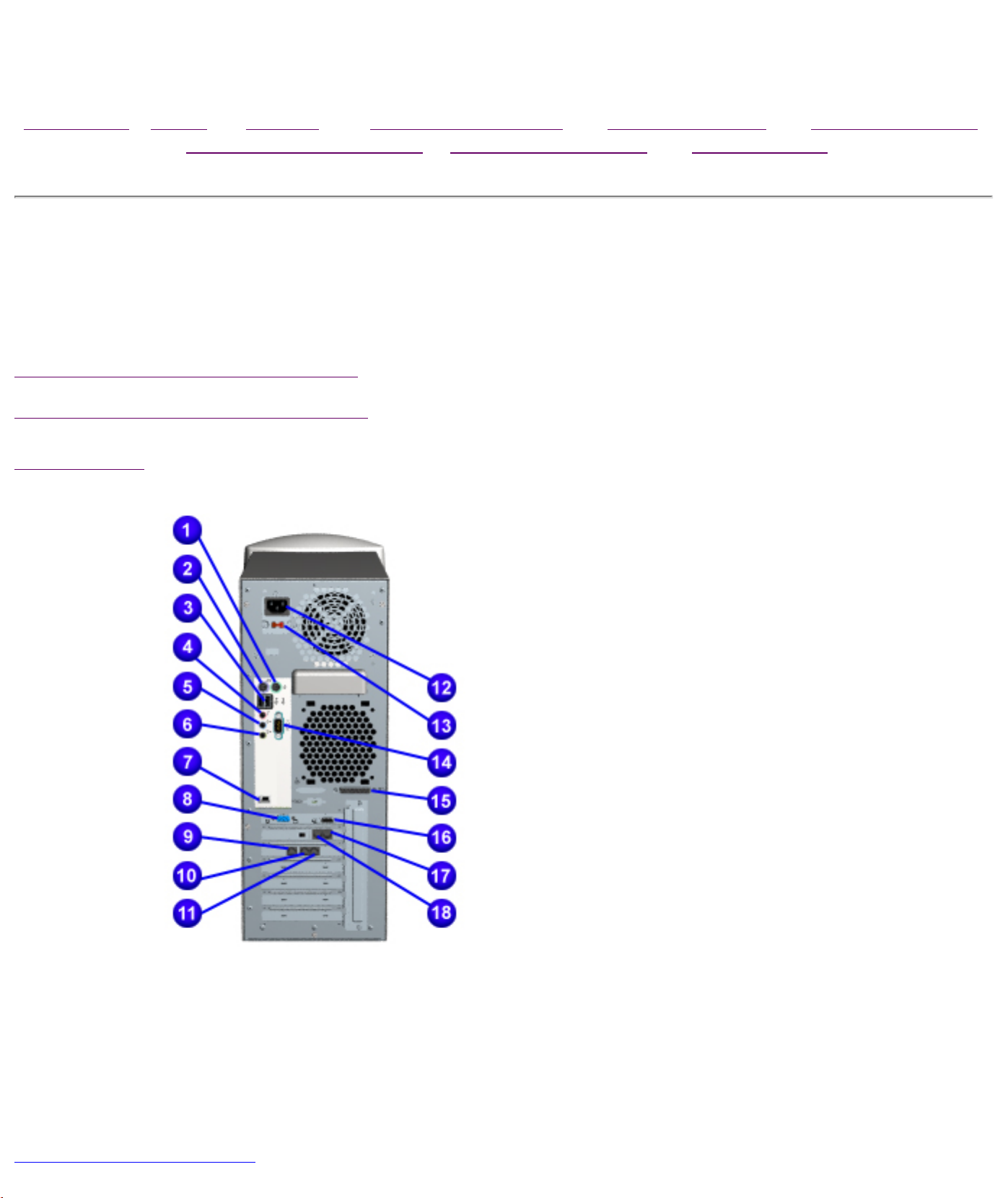
Product Description
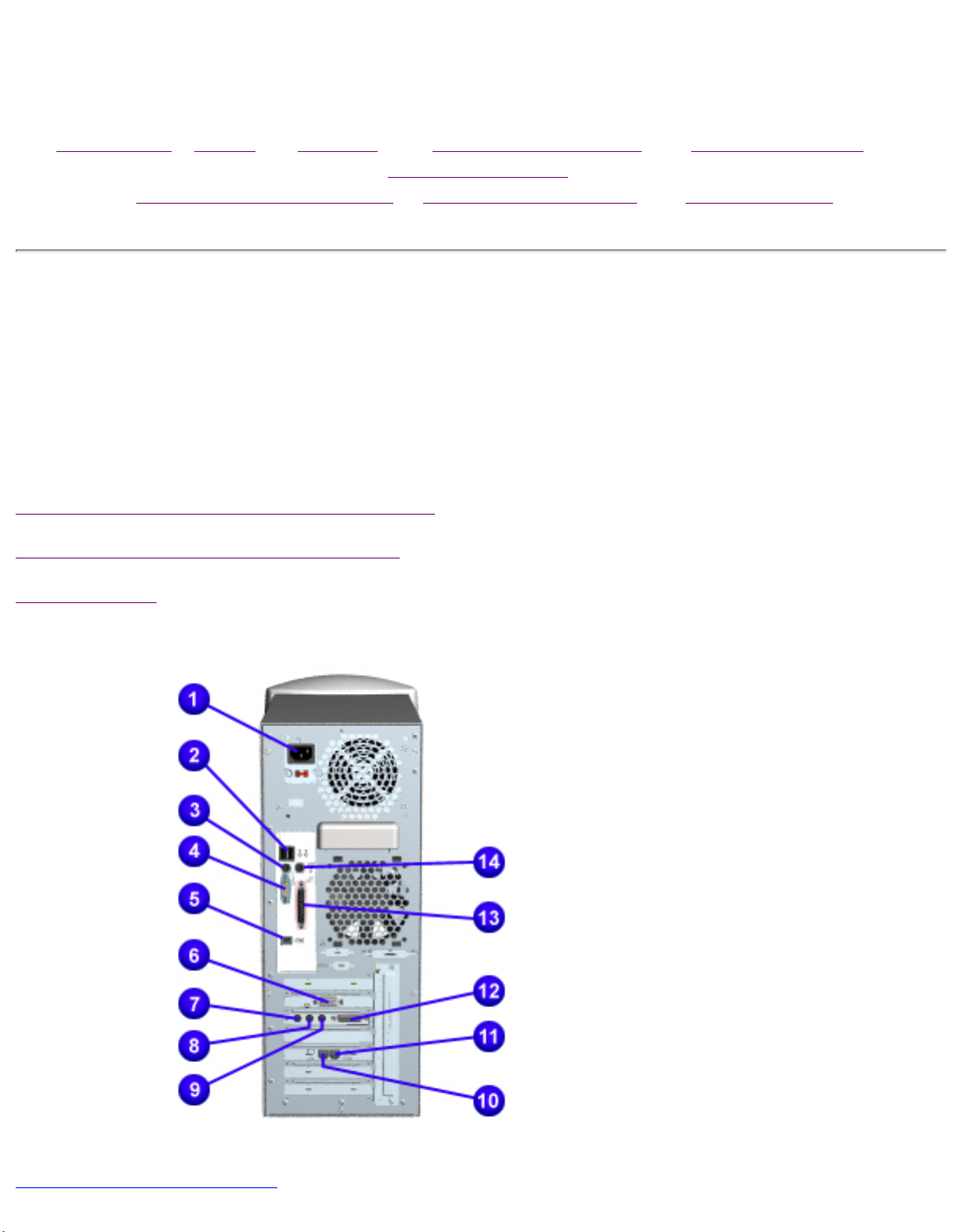
CPU Back Connectors for Models 5852 and 5863
5800 Models with Athlon System Board
5800 Models with Celeron System Board
Connector Pins
1
Mouse connector
2
Keyboard connector
3
USB (Universal Serial Bus)
connectors*
4
Microphone
5
Audio in
6
Audio out
7
IEEE 1394 connector*
8
VGA connector
9
Ethernet RJ45 connector*
10
RJ11 connector to wall*
11
RJ11 connector to telephone*
12
AC power connector
13
Voltage select switch
14
Serial port
15
Parallel port
Back to Product Description
16
Digital Flat Panel connector**
17
Telephone line to wall outlet
18
Telephone line to telephone
* On selected models only
** Includes TV out on Europe, Middle
East, and Africa (EMEA) models only
Maintenance & Service Guide
Presario 5800 Series Personal Computers
MSG Index | Home | Preface | Product Description | Troubleshooting |
Illustrated Parts
Removal & Replacement | Jumpers & Switches | Specifications
Product Description
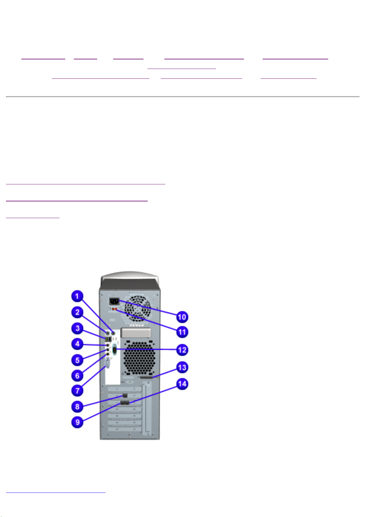
CPU Back Connectors for Models 5831, 5837, 5838, 5855,
5858, 5861,
5868, 5875 and 5888
5800 Models with Pentium III System Board
5800 Models with Celeron System Board
Connector Pins
1
Power
Connector
2
Dual USB
3
Keyboard
4
Serial Port
5
IEEE 1394
Connector
6
SVGA Monitor
Port
7
Microphone
8
Audio In
9
Audio Out
10
Modem Line Out
Back to Product Description
11
Modem Line In
12
Game Port
13
Parallel Port
14
Scroll Mouse
Maintenance & Service Guide
Presario 5800 Series Personal Computers
MSG Index | Home | Preface | Product Description | Troubleshooting |
Illustrated Parts
Removal & Replacement | Jumpers & Switches | Specifications
Product Description
CPU Back Connectors for Models 5822, 5827, 5832, 5834
and 5835
5800 Models with Pentium III System Board
5800 Models with Athlon System Board
Connector Pins
1
Mouse
connector
2
Keyboard
connector
3
USB (Universal
Serial Bus)
connectors*
4
Microphone in
5
Audio in
6
Audio out
7
SVGA monitor
port
Back to Product Description
8
Modem
9
Ethernet RJ45
connector*
10
AC power
connector
11
Voltage select
switch
12
Serial port
13
Parallel port
* On selected models only
Maintenance & Service Guide
Presario 5800 Series Personal Computers
MSG Index | Home | Preface | Product Description | Troubleshooting | Illustrated
Parts
Removal & Replacement | Jumpers & Switches | Specifications
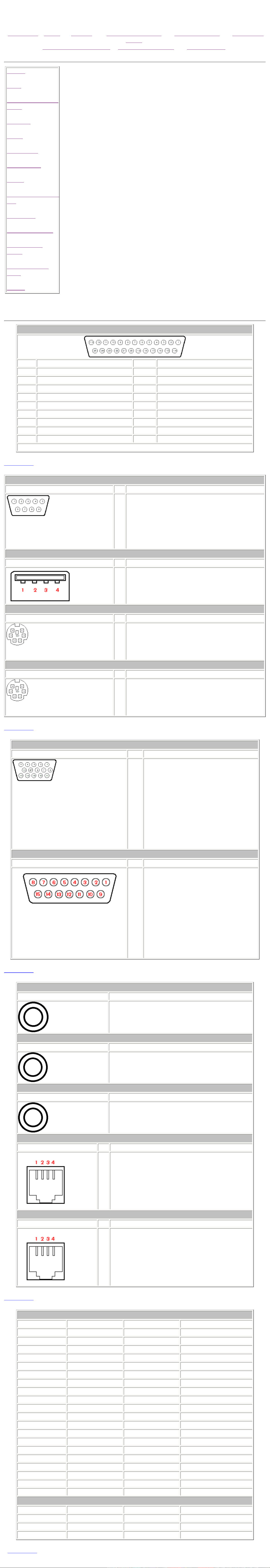
Parallel
Serial
Universal Serial Bus
(USB)
Keyboard
Mouse
VGA Monitor
MIDI/Joystick
Line-in
Connector Pin Assignments
This section contains the connector pin assignments for the Presario 5800 series
of personal computers.
Speaker/Headphone
Out
Microphone
Phone Line to Wall
Phone Line to
Phone
DVD-Drive Data
Cable
Modem
Parallel Connector
Pin Signal Pin Signal
1 Strobe* 10 Acknowledge*
2 Data Bit 0 11 Busy
3 Data Bit 1 12 Paper Out
4 Data Bit 2 13 Select
5 Data Bit 3 14 Auto Linefeed*
6 Data Bit 4 15 Error*
7 Data Bit 5 16 Initialize Printer*
8 Data Bit 6 17 Select In*
9 Data Bit 7 18-25 Signal Ground
* = Active low
Back to Top
Serial Connector
Connector Pin Signal
1
Carrier Detect
2
Receive Data
3
Transmit Data
4
Data Terminal Ready
5
Signal Ground
6
Data Set Ready
7
Ready to Send
8
Clear to Send
9
Ring Indicator
Universal Serial Bus
Connector Pin Signal
1
- Data
2
+Data
3
Ground
4
+5 VDC
Keyboard
Connector Pin Signal
1
Data
2
Unused
3
Ground
4
+5 VDC
5
Clock
6
Unused
Mouse
Connector Pin Signal
1
Data
2
Unused
3
Ground
4
+5 VDC
5
Clock
6
Unused
Back to Top
VGA Monitor
Connector Pin Signal
1
2
3
4
5
6
7
8
9
10
11
12
13
14
15
Red Analog
Green Analog
Blue Analog
Volume Up
Ground
Ground Analog
Ground Analog
Ground Analog
+5 VDC
Ground
Volume Down
DDC Data
Horizontal Sync
Vertical Sync
DDC Clock
MIDI/Joystick
Connector Pin Signal
Back to Top
1
2
3
4
5
6
7
8
9
10
11
12
13
14
15
+5 VDC
Fire A (1)
X-Axis (1)
GND
GND
Y-Axis (1)
Fire B (1)
+5 VDC
+5 VDC
Fire A (2)
X-Axis (2)
MIDI Out
Y-Axis (2)
Fire B (2)
MIDI In
Line In
Connector Connector
Stereo 1/8" Miniphone
Speaker/Headphone Out
Connector Connector
Stereo 1/8" Miniphone
Microphone
Connector Connector
Stereo 1/8" Miniphone
Phone Line to Wall Jack
Connector Pin Signal
1
Unused
2
Tip
3
Ring
4
Unused
Phone Line to Phone
Connector Pin Signal
Unused
1
2
Tip
3
Back to Top
Pin Signal Pin Signal
1 RESET 21 DMARK
2 GND 22 GND
3 DD7 23 -DIOW
4 DD8 24 GND
5 DD6 25 -DIOR
6 DD9 26 GND
Ring
4
Unused
DVD Drive Data Cable
7 DD5 27 IORDY
8 DD10 28 SPSYNC
9 DD4 29 -DMACK
10 DD11 30 GND
11 DD3 31 INTRQ
12 DD12 32 -IOCS16
13 DD2 33 DA0
14 DD13 34 -PDIA6
15 DD1 35 DA0
16 DD14 36 DAZ
17 DD0 37 -CS1FX
18 DD15 38 -C53FX
19 GND 39 -DASP
20 (KEY) 40 GNP
Internal Fax/Modem
Pin Signal Pin Signal
1 Unused 4 Tip
2 Unused 5 Unused
3 Ring 6 Unused
Back to Top
Maintenance & Service Guide
Presario 5800 Series Personal Computers
MSG Index | Home | Preface | Product Description | Troubleshooting | Illustrated Parts
Removal & Replacement | Jumpers & Switches | Specifications
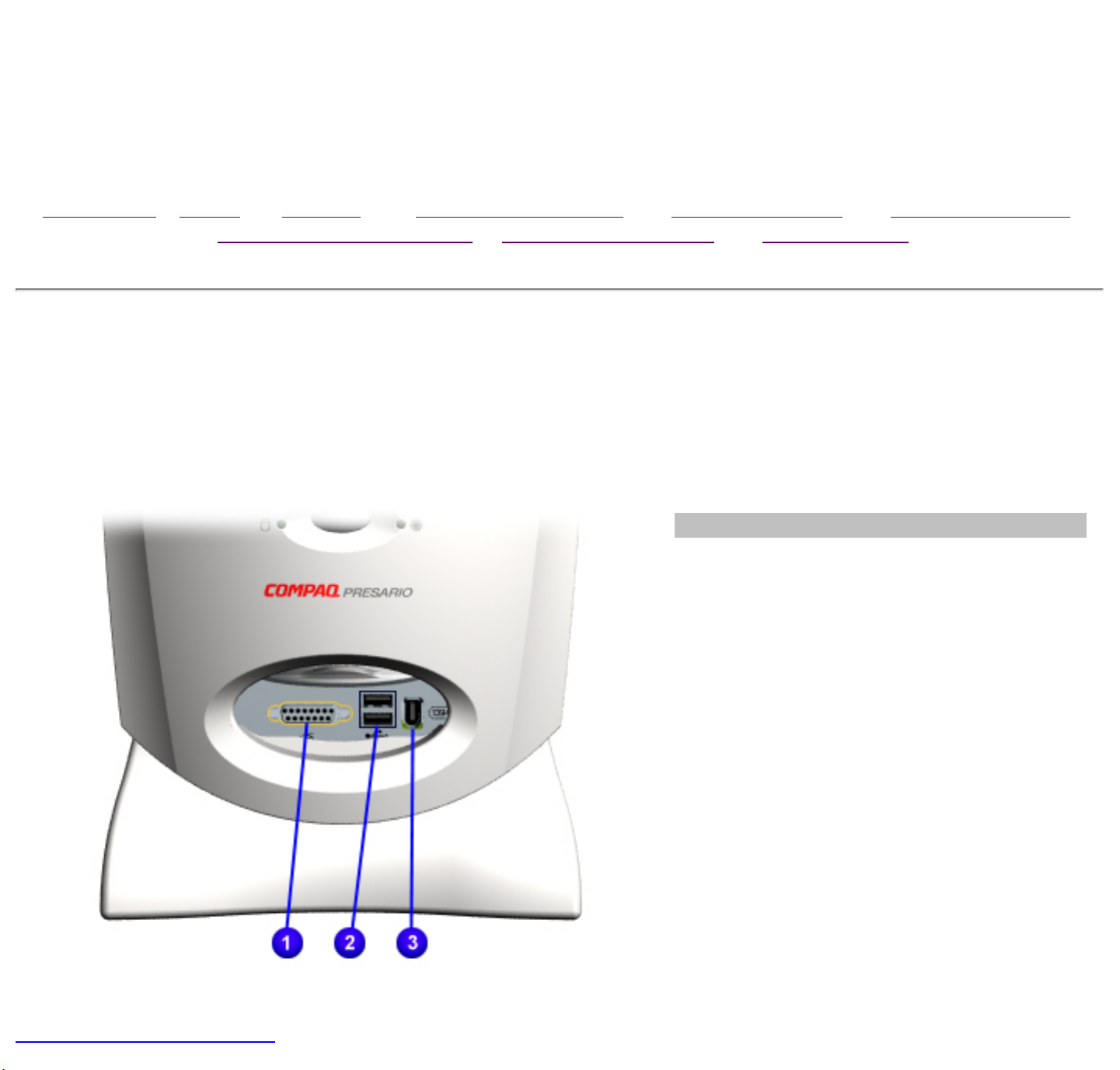
Product Description
Digital Creativity Imaging Center/Creativity Action Center
Description
1
Gamepad/Joystick Port*
2
USB (Universal Serial Bus) connector
3
IEEE 1394 connector*
* Available on select models only
Back to Product Description

Maintenance & Service Guide
Presario 5800 Series Personal Computers
MSG Index | Home | Preface | Product Description | Troubleshooting |
Illustrated Parts
Removal & Replacement | Jumpers & Switches | Specifications
Product Description
Power Management Features
Compaq Presario 5800 Series Personal Computers use ACPI (Advanced Configuration and Power
Interface) for system power management. ACPI is an open industry specification that provides
reliable power management through improved hardware and operating system coordination.
The following is a list of the power management features:
● Power Status Lights. You can quickly tell the sleep condition of the system by glancing at
the Power Status Lights on the unit or keyboard.
● Automatic Sleep. In Windows 98, there are different Power Schemes under which the
system goes into Sleep mode automatically when it times out. The optional settings for
Windows 98 are Home/Office Desk, Portable/Laptop and Always On. The system
supports different levels of power management for varying patterns of computer usage.
● Default and Adjustable timeout settings. The default setting for Sleep timeout is 30
minutes. The Sleep timeout value can be set in the Control Panel by clicking the Power
Management icon. At the Properties screen, click System Standby, Turn off Monitor,
and Turn off Hard Disk to set the length of time before the system goes to sleep.
● Manual Sleep. To manually put your computer into sleep mode in the Windows 98 desktop,
press the Sleep button (on the keyboard). The power status light on the CPU will light to
show that Sleep mode is activated.
● Other manual standby options. Another way to put your computer into sleep mode
manually under Windows 98 is to select Start, then Shutdown. Select Standby from the list
of choices to put the system into Sleep mode. The system can then be turned off or left in
Sleep. When the Sleep button is pressed, the system returns to the previous Windows 98
Desktop state.
● Wake up events. Events that bring a system back to the working state include:
■ Pressing the Sleep button on the keyboard
■ Pressing the CPU Power button
■ Fax/Modem answers a call
● Synchronized software and hardware volume control buttons.
Top
States of Power Management
Power management can be defined by three distinct power states in which the computer operates:
On, Off, and Sleep. The following table describes the power states and lists the power consumption
of each state:
Power Management States
Energy State Description Power Consumption
On Power is available to the system. The
AC cable is connected, and the power
status light is green.
Off Power is not available to the system
and the AC cable is disconnected. The
power status light is not lit.
Soft Off Power is available to the system, the
AC cable is connected, and the power
LED is off.
90 Watts avg., 110 Watts max
0 Watts
1-2 Watts
Sleep Power is available to the system, the
AC cable is connected, and the
computer is in a low power/standby
mode. The power status light is
amber.
Top
Back to Product Description
27 Watts

Maintenance & Service Guide
Presario 5800 Series Personal Computers
MSG Index | Home | Preface | Product Description | Troubleshooting |
Illustrated Parts
Removal & Replacement | Jumpers & Switches | Specifications
Product Description
Power Cord Set Requirements
The voltage select switch feature on the computer allows it to operate from any line voltage
between 120 and 240 volts AC.
The power cord set (flexible cord and wall plug) supplied with the computer meets the
requirements for use in the country where the computer was purchased.
Power cord sets for use in other countries must meet the requirements of the country where the
computer is used. For more information on power cord set requirements, contact a Compaq
authorized dealer, reseller, or service provider.
general
General Requirements
The requirements listed below are applicable to all countries.
1. The length of the power cord set must be at least 6.00 feet (1.8 m) and no longer than 9.75
feet (3.0 m).
2. All power cord sets must be approved by an acceptable accredited agency responsible for
evaluation in the country where the power cord set will be used.
3. The power cord set must have a minimum current capacity of 10A and a nominal voltage
rating of 125 or 250 volts AC, as required by each country's power system.
4. The appliance coupler must meet the mechanical configuration of an EN 60 320/IEC 320
Standard Sheet C13 connector, for mating with appliance inlet on the Switch Box.
Country-Specific Requirements
Power Cord Set Requirements by Country
Country Accredited
Agency
Australia EANSW 1
Austria OVE 1
Belgium CEBC 1
Canada CSA 2
Denmark DEMKO 1
Finland SETI 1
France UTE 1
Applicable Note
Numbers
Germany VDE 1
Italy IMQ 1
Japan JIS 3
Norway NEMKO 1
Sweden SEMKO 1
Switzerland SEV 1
United Kingdom BSI 1
United States UL 2
NOTES:
1. The flexible cord must be <HAR> Type HO3VV-F, 3-conductor, 1.0 mm2 conductor size. Power
cord set fittings (appliance coupler and wall plug) must bear the certification mark of the agency
responsible for evaluation in the country where it will be used.
2. The flexible cord must be Type SJT-2 or equivalent, No. 18 AWG, 3-conductor. The wall plug
must be a two-pole grounding type with a NEMA 5-15P (15A, 125V) or NEMA 6-15P (15A, 250V)
configuration.
3. The appliance coupler, flexible cord, and wall plug must bear a "T" mark and registration
number in accordance with the Japanese Dentori Law. Flexible cord must be Type VCT or VCTF, 3conductor, 0.75mm2 conductor size. The wall plug must be a two-pole type with a Japanese
Industrial Standard C8303 (15A, 125V) configuration.
Back to Product Description
Maintenance & Service Guide
Presario 5800 Series Personal Computers
MSG Index | Home | Preface | Product Description | Troubleshooting |
Illustrated Parts
Removal & Replacement | Jumpers & Switches | Specifications
Troubleshooting
Troubleshooting
Clearing CMOS
Power-On Self-Test (POST)
Diagnostic Error Codes
Troubleshooting Without Diagnostics
This section provides troubleshooting information for
Compaq Presario 5800 Series Personal Computers.
Power-On Self-Test (POST) messages, diagnostic error
codes, and memory error codes appear in tables.
The message and code tables include a description of the
error, the probable cause, and the recommended action
that should be taken to resolve the error condition.
Adherence to the procedures and precautions described
in this section is essential for proper service.
Maintenance & Service Guide
Presario 5800 Series Personal Computers
MSG Index | Home | Preface | Product Description | Troubleshooting |
Illustrated Parts
Removal & Replacement | Jumpers & Switches | Specifications
Troubleshooting
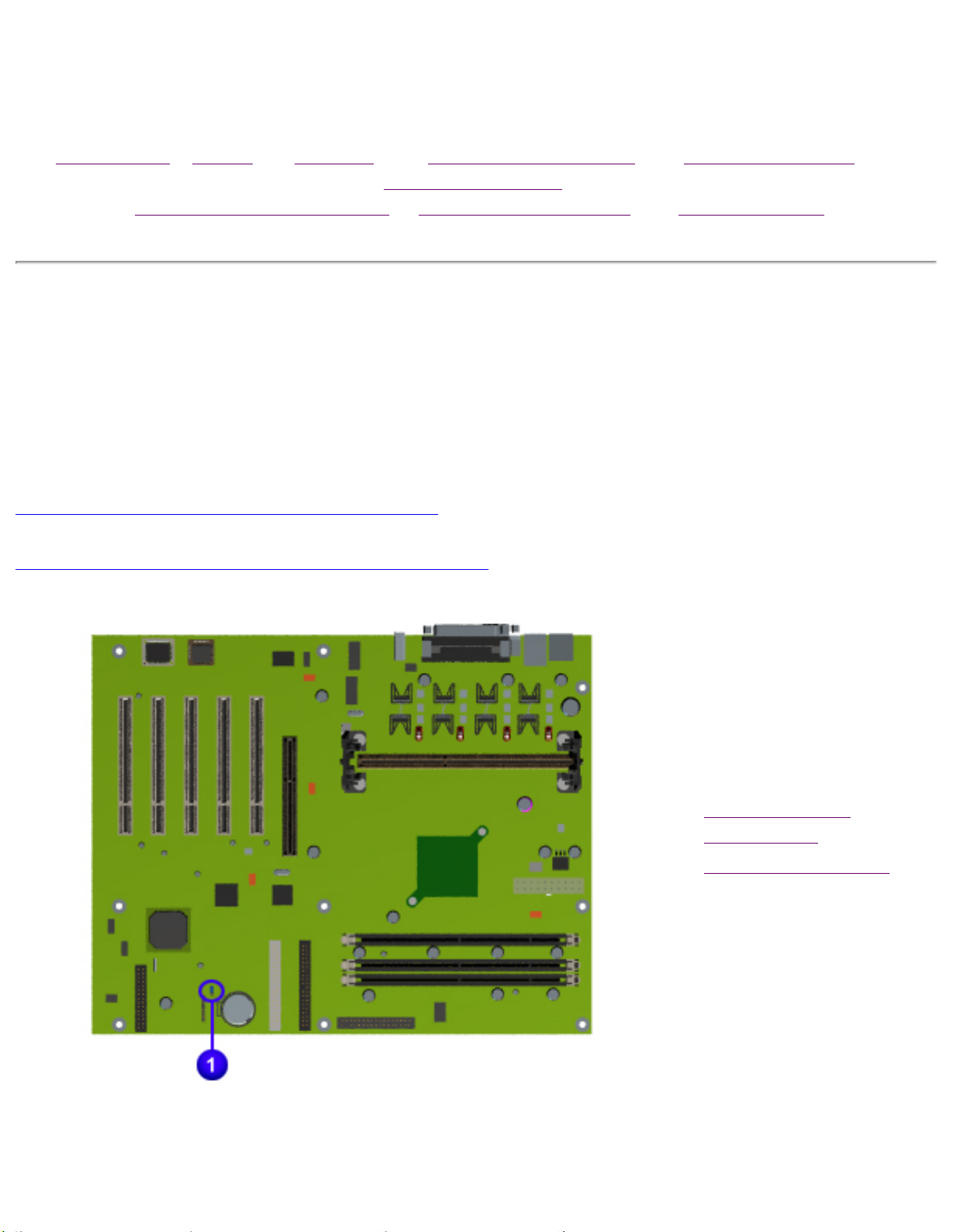
Clearing CMOS for Models 5831, 5837, 5838, 5855, 5858,
5861, 5868, 5875 and 5888
5800 Models with Celeron System Board
5800 Models with Pentium III System Board
If the power-on password
is not known, clearing
CMOS will disable the
power-on password. To
clear CMOS, complete the
following steps:
1.
Complete the
preparation for
disassembly.
2.
Remove the chassis.
3.
To disable the
password, move the
jumper
at J3 from 2-3 to 1-2.
Password Jumper Location
4.
Wait for 10 seconds.
5.
Move the jumper at J3
from 1-2 to 2-3.
6.
Replace the chassis
and perform the
appropriate
troubleshooting.
Maintenance & Service Guide
Presario 5800 Series Personal Computers
MSG Index | Home | Preface | Product Description | Troubleshooting |
Illustrated Parts
Removal & Replacement | Jumpers & Switches | Specifications
Troubleshooting
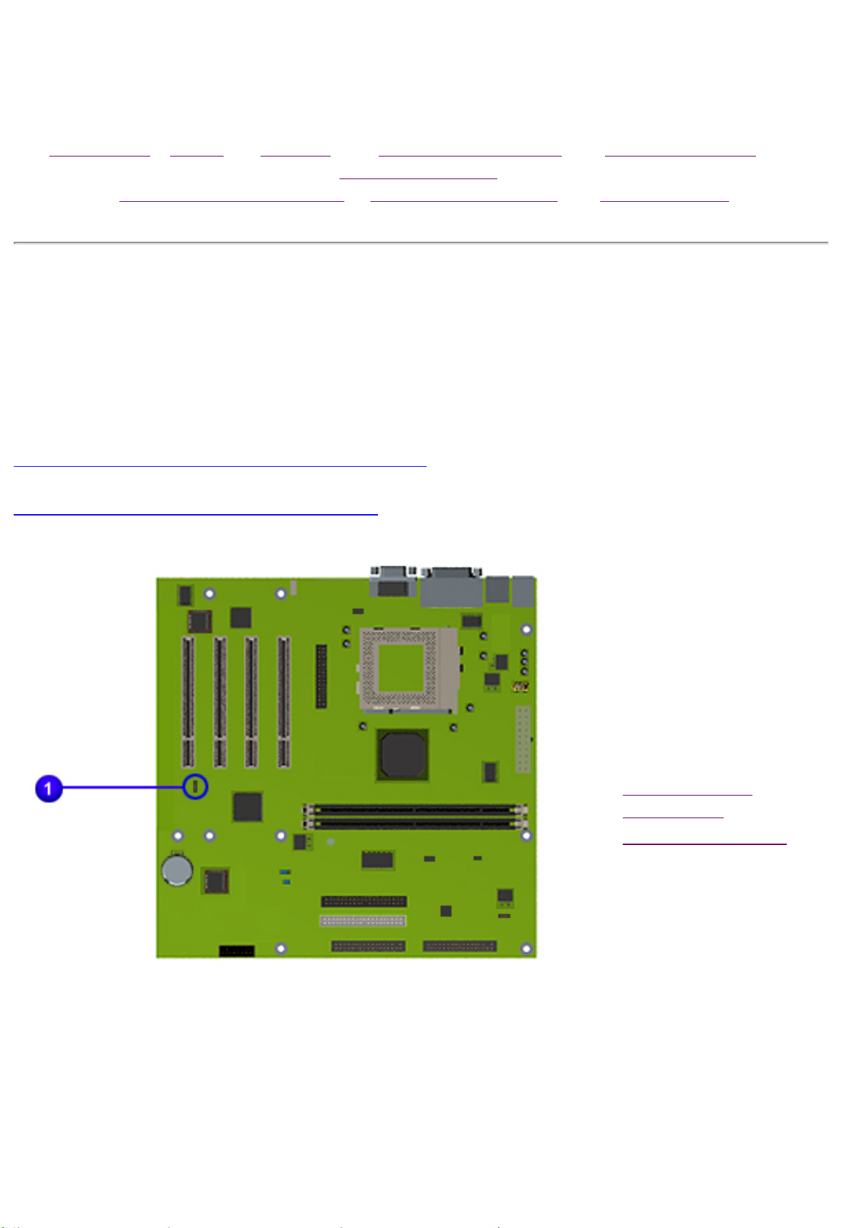
Clearing CMOS for Models 5822, 5827, 5832, 5834 and
5835
5800 Models with Pentium III System Board
5800 Models with Athlon System Board
If the power-on password
is not known, clearing
CMOS will disable the
power-on password. To
clear CMOS, complete the
following steps:
1.
Complete the
preparation for
disassembly.
2.
Remove the chassis.
3.
To disable the
password, move the
jumper
at JP1 from 1-2 to 2-
3.
4.
Wait for ten seconds.
5.
Move the jumper at
JP1 from 2-3 to 1-2.
6.
Replace the chassis
and perform the
appropriate
troubleshooting.
Maintenance & Service Guide
Presario 5800 Series Personal Computers
MSG Index | Home | Preface | Product Description | Troubleshooting |
Illustrated Parts
Removal & Replacement | Jumpers & Switches | Specifications
Troubleshooting
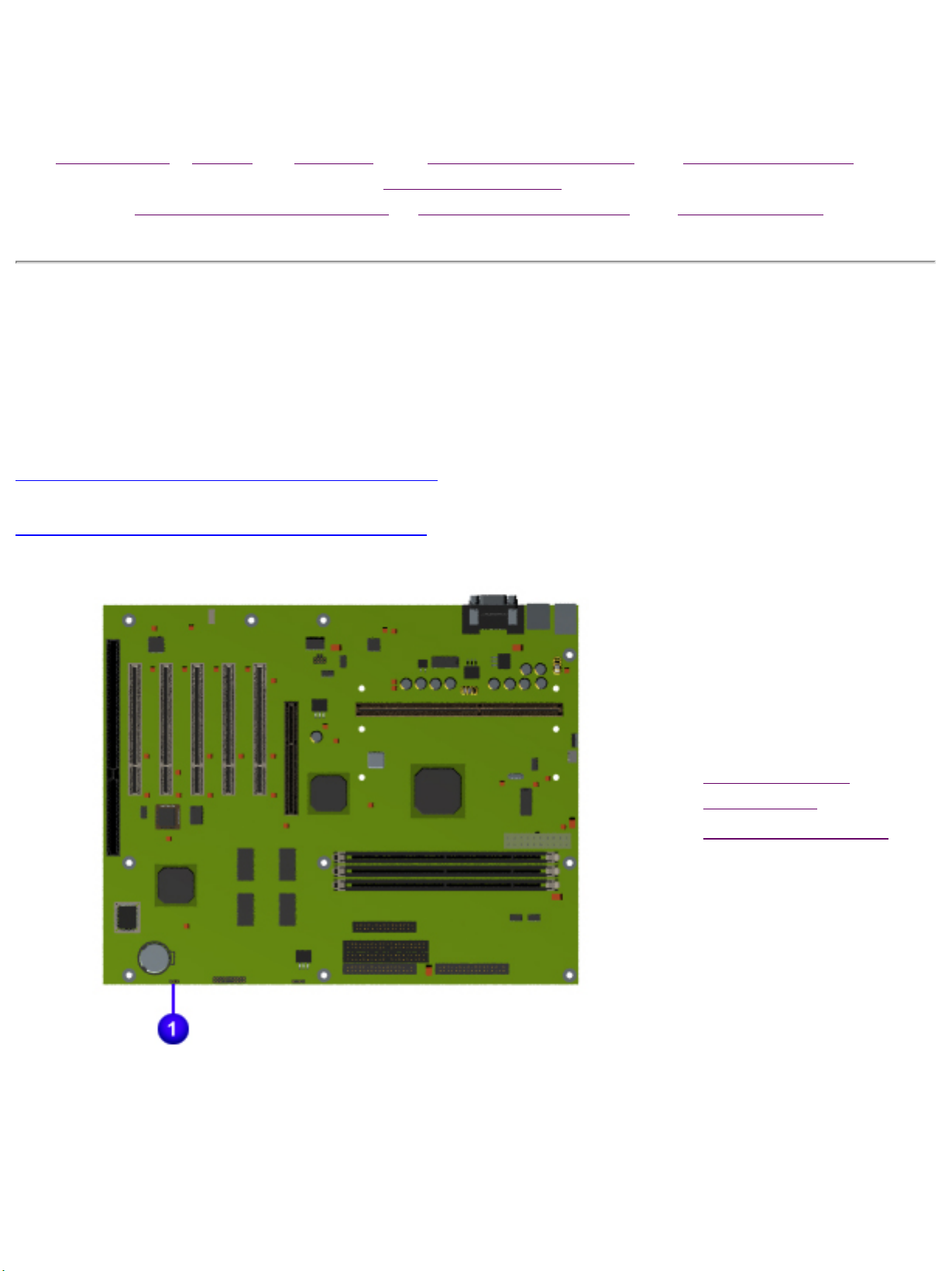
Clearing CMOS for Models 5852 and 5863
5800 Models with Celeron System Board
5800 Models with Athlon System Board
If the power-on password
is not known, clearing
CMOS will disable the
power-on password. To
clear CMOS, complete the
following steps:
1.
Complete the
preparation for
disassembly.
2.
Remove the chassis.
3.
To disable the
password, move the
jumper
at JP1 from 1-2 to 2-
3.
Password Jumper Location
4.
Wait for 10 seconds.
5.
Move the jumper at
JP1 from 2-3 to 1-2.
6.
Replace the chassis
and perform the
appropriate
troubleshooting.

Maintenance & Service Guide
Presario 5800 Series Personal Computers
MSG Index | Home | Preface | Product Description | Troubleshooting |
Illustrated Parts
Removal & Replacement | Jumpers & Switches | Specifications
Troubleshooting
Power-On Self-Test (POST)
POST is a series of diagnostic tests that run automatically when the system is turned on. After
the computer is turned on, POST checks the following assemblies to ensure that the computer
system is functioning properly:
● Keyboard
● System board
● Memory modules
● Video memory
● Diskette drive
● Hard drive
● CD (or DVD) drive
● Power supply
POST also detects the type of mass storage devices installed in the computer.
If POST finds an
error in the system, an error condition is indicated by an audible or visual
message.
Maintenance & Service Guide
Presario 5800 Series Personal Computers
MSG Index | Home | Preface | Product Description | Troubleshooting | Illustrated Parts
Removal & Replacement | Jumpers & Switches | Specifications
POST (Power-On Self-Test) Error Messages
An error message displays if the POST encounters a problem. This self-test will run automatically each time the
system is powered on. The self-test will check all assemblies within the computer and report any errors found.
Click on the desired error code for the probable cause of the error and a recommended course of action.
Diskette Drive A or B Error Failing Bits nnn Fixed Disk Controller Failure
Extended RAM failed at offset nnn Fixed Disk 0 or 1 Failure Incorrect Drive A Type
Invalid NVRAM Media Type Keyboard Controller Error Keyboard Error
Operating System Not Found Parity Check 1 Parity Check 2
Real Time Clock Error System Battery is Dead System BIOS Shadowed
System Cache Error System CMOS Checksum Bad System RAM Failed at Offset, nnn
System Timer Error UMB Upper Limit Segment Address
nnn
Video BIOS Shadowed
Diskette Drive A or B Error
Probable Cause Recommended Action
Drive A: is present, but fails the BIOS POST diskette tests 1. Run Setup.
2. Replace the signal
cables.
3. Replace the drive.
Back to Top
Extended RAM failed at offset nnn
Probable Cause Recommended Action
Extended memory not working or not configured properly 1. Replace the memory
modules.
2. Replace the system
board.
Back to Top
Failing Bits nnn
Probable Cause Recommended Action
nnn is a map of the bits at the RAM address which failed the
memory test
1. Run Setup.
2. Replace the system
board.
Back to Top
Fixed Disk 0 or 1 Failure
Probable Cause Recommended Action
Hard drive is not working or configured properly 1. Run Setup.
2. Replace the signal cable.
3. Replace the hard drive.
Back to Top
Fixed Disk Controller Failure
Probable Cause Recommended Action
Hard drive is not working or configured properly 1. Run Setup.
2. Replace the system
board.
Back to Top
Incorrect Drive A Type
Probable Cause Recommended Action
Type of diskette drive A: not correctly identified 1. Run Setup.
2. Replace the diskette
drive.
Back to Top
Invalid NVRAM Media Type
Probable Cause Recommended Action
Problem with NVRAM (CMOS) access Replace the system board.
Back to Top
Keyboard Controller Error
Probable Cause Recommended Action
Keyboard, I/O keyboard controller
(on system board) or mouse error
1. Replace the keyboard.
2. Replace the mouse.
3. Replace the system
board.
Back to Top
Keyboard Error
Probable Cause Recommended Action
Keyboard, I/O keyboard controller
(on system board) or mouse error
1. Replace the keyboard.
2. Replace the mouse.
3. Replace the system
board.
Back to Top
Operating System Not Found
Probable Cause Recommended Action
Operating system cannot be located on
either drive A: or C:
Run Setup.
Back to Top
Parity Check 1
Probable Cause Recommended Action
Parity error found in the system bus 1. Run Setup.
2. Replace the memory
modules.
3. Replace the system
board.
Back to Top
Parity Check 2
Probable Cause Recommended Action
Parity error found in the I/O bus 1. Run Setup.
2. Replace the ISA board
(modem).
Back to Top
Real Time Clock Error
Probable Cause Recommended Action
Real-time clock fails BIOS test Replace the system board.
Back to Top
System Battery is Dead
Probable Cause Recommended Action
RTC battery is dead 1. Replace the RTC battery.
2. Run Setup.
Back to Top
System BIOS Shadowed
Probable Cause Recommended Action
System BIOS copied to Shadow RAM Replace the system board.
Status message only; no
action required.
Back to Top
System Cache Error
Probable Cause Recommended Action
RAM cache failed the BIOS test Run Setup.
Back to Top
System CMOS Checksum Bad
Probable Cause Recommended Action
CMOS is corrupted or modified incorrectly Run Setup.
Back to Top
System RAM Failed at Offset, nnn
Probable Cause Recommended Action
System RAM failed Replace memory modules.
Back to Top
System Timer Error
Probable Cause Recommended Action
DMA, timers, etc. Replace the system board.
Back to Top
UMB Upper Limit Segment Address nnn
Probable Cause Recommended Action
Displays the address nnn of the upper limit
of Upper Memory Blocks, indicating released segments of the
BIOS
Run Setup.
Status message only; no
action required.
Back to Top
Video BIOS Shadowed
Probable Cause Recommended Action
Video BIOS successfully copied to shadow RAM Run Setup.
Status message only; no
action required.
Back to Top
Maintenance & Service Guide
Presario 5800 Series Personal Computers
MSG Index | Home | Preface | Product Description | Troubleshooting |
Illustrated Parts
Removal & Replacement | Jumpers & Switches | Specifications
Troubleshooting
Diagnostic Error Codes
Diagnostic error codes occur if the system recognizes a problem while running the Compaq
Utilities TEST program. These error codes help identify possible defective subassemblies.
Retest the system after completing each
IMPORTANT:
For assistance in the removal and replacement of a particular subassembly, see Removal and
Replacement Procedures.
Click on the desired error code range or corresponding test for a list of descriptions of each error
condition and actions required to resolve the error condition.
step. At the point where the problem is
resolved, do not proceed with the remaining
steps.
Error Code
Test
Range
101-199 Processor Test
200-210 Memory Test
301-304 Keyboard Test
400-498 Parallel Printer Test
501-516 Video Display Unit Test
600-699 Diskette Drive Test
802-824 Monochrome Video Test
1101-1109 Serial Test
1201-1210 Modem Communications Test
1700-1799 Hard Drive Test
2402-2480 Video Test
3206 Audio Test
3301-3305
66xx
8601 Pointing Interface Device Test
CD or DVD Drive Test
Processor Test Error Codes
Error Code Description Recommended Action
101-xx CPU test failed Replace the system board and retest.
102-xx Processor error 1. Run Computer Checkup or Setup
and retest.
2. Replace the processor and retest.
103-xx DMA controller failed Replace the system board and retest.
104-xx Interrupt controller failed Replace the system board and retest.
105-xx Port error Replace the system board and retest.
106-xx Keyboard controller self-test
failed
107-xx CMOS RAM test failed The following steps apply to error codes 107-
Replace the system board and retest.
xx through 109-xx:
108-xx CMOS interrupt test failed
109-xx CMOS clock test failed
110-xx Programmable timer test failed The following step applies to error codes 110111-xx Refresh detect test failed
112-xx Speed test failed
113-01 Protected mode test failed
114-xx Speaker test failed 1. Verify the speaker connection.
199-xx Installed devices test failed 1. Check system configuration.
1. Replace the battery/clock module and
retest.
2. Replace the system board and retest.
xx through 113-01:
Replace the system board and retest.
2. Replace the system board and retest.
2. Verify cable connections.
3. Check switch settings.
Top
Error
Code
200-xx Invalid memory
Description Recommended Action
configuration
4. Run Compaq Utilities.
5. Replace the system board and retest.
Memory Test Error Codes
1. Verify memory module value compatibility.
2. Reinsert memory in the correct location.
201-xx Memory machine ID test
failed
202-xx Memory system ROM
checksum failed
203-xx Memory write/read test
failed
204-xx Memory address test failed
206-xx Increment pattern test
failed
210-xx Random pattern test failed
The following steps apply to error codes 201-xx and
202-xx:
1. Flash the ROM and retest.
2. Replace the memory and retest.
3. Replace the system board and retest.
The following steps apply to error codes 203-xx
through 210-xx:
1. Remove one memory module at a time until the
error message stops.
2. Replace other removed modules one at a time,
testing each to ensure the error does not return.
3. Replace the system board and retest.
Top
Keyboard Test Error Codes
Error
Code
301-xx Keyboard short test, 8042
302-xx Keyboard long test failed
303-xx Keyboard LED test, 8042
304-xx Keyboard typematic test
Description Recommended Action
self-test failed
self-test failed
failed
The following steps apply to error codes 301-xx
through 304-xx:
1. Check the keyboard connection. If disconnected,
turn the computer off and connect the keyboard.
2. Replace the keyboard and retest.
3. Replace the system board and retest.
Top
Parallel Printer Test Error Codes
Error
Code
401-xx Printer failed or not
402-xx Printer data register failed
403-xx Printer pattern test failed
498-xx Printer failed or not
Description Recommended Action
connected
connected
The following steps apply to error codes 401-xx through
498-xx:
1. Connect the printer.
2. Check power to the printer.
3. Install the loop-back connector and retest.
4. Replace system board and retest.
Top
Video Display Unit Test Error Codes
Error
Code
501-xx Video controller test failed The following step applies to error
502-xx Video memory test failed
503-xx Video attribute test failed
504-xx Video character set test failed
505-xx Video 80 x 25 mode 9 x 14 character cell test
506-xx Video 80 x 25 mode 9 x 14 character cell test
507-xx Video 40 x 25 mode test failed
Description Recommended Action
codes
501-xx through 516-xx:
Replace the system board and
retest.
failed
failed
508-xx Video 320 x 200 mode color set 0 test failed
509-xx Video 320 x 200 mode color set 1 test failed
510-xx Video 640 x 200 mode test failed
511-xx Video screen memory page test failed
512-xx Video gray scale test failed
514-xx Video white screen test failed
516-xx Video noise pattern test failed
Top
Diskette Drive Test Error Codes
Error
Code
Description Recommended Action
600-xx Diskette ID drive types test failed The following steps apply to error
601-xx Diskette format failed
602-xx Diskette read test failed
603-xx
604-xx
605-xx Diskette ID media test failed
606-xx Diskette speed test failed
607-xx Diskette wrap test failed
608-xx Diskette write-protect test failed
609-xx Diskette reset controller test failed
610-xx Diskette change line test failed
694-xx Pin 34 is not cut on 360KB diskette drive
697-xx Diskette type error
698-xx Diskette drive speed not within limits
Diskette write, read, compare test failed
Diskette random seek test failed
codes 600-xx through 698-xx:
1. Replace the diskette and retest.
2. Check and/or replace the
diskette power and signal cables
and retest.
3. Replace the diskette drive and
retest.
4. Replace the system board and
retest.
699-xx Diskette drive/media ID error 1. Replace media.
2. Run Setup.
Top
Monochrome Video Test Error Codes
Error
Code
802-xx Video memory test failed The following step applies to error codes 802824-xx Monochrome video text mode test
Description Recommended Action
xx through 824-xx:
failed
Replace the system board and retest.
Top

Maintenance & Service Guide
Presario 5800 Series Personal Computers
MSG Index | Home | Preface | Product Description | Troubleshooting |
Illustrated Parts
Removal & Replacement | Jumpers & Switches | Specifications
Diagnostic Error Codes
Diagnostic error codes occur if the system recognizes a problem while running the Compaq
Utilities TEST program. These error codes help identify possible defective subassemblies.
Retest the system after completing each step.
IMPORTANT:
For assistance in the removal and replacement of a particular subassembly, see
Replacement Procedures.
Click on the desired error code range or corresponding test for a description of each error
condition and actions required to resolve the error condition.
If the problem has been resolved, do not
proceed with the remaining steps.
Removal and
Error Code
Test
Range
101-199 Processor Test
200-210 Memory Test
301-304 Keyboard Test
400-498 Parallel Printer Test
501-516 Video Display Unit Test
600-699 Diskette Drive Test
802-824 Monochrome Video Test
1101-1109 Serial Test
1201-1210 Modem Communications Test
1700-1799 Hard Drive Test
2402-2480 Video Test
3206 Audio Test
3301-3305
66xx
8601 Pointing Interface Device Test
CD or DVD Drive Test
Top
Serial Test Error Codes
Error
Code
1101-xx Serial Port Test The following steps apply to error codes 1101-
1109-xx Clock Register Test 1. Check the switch settings on the
Top
Description Recommended Action
xx through 1109-xx:
serial/parallel device, if applicable.
2. Replace the system board and retest.
Modem Communications Test Error Codes
Error
Code
1201-xx Modem Internal Loop-Back Test The following steps apply to error codes 1201-
1202-xx Modem Time-Out Error 1. Refer to modem documentation for correct
1203-xx Modem External Termination Test 2. Check the modem line.
1204-xx Modem Auto Originate Test 3. Replace the modem and retest.
1206-xx Dial Multifrequency Tone Test
1210-xx Modem Direct Connect Test
Top
Description Recommended Action
xx through 1210-xx:
Setup procedures.
Hard Drive Test Error Codes
Error
Code
1700-xx Hard drive ID types test failed The following steps apply to error codes 1700-
1701-xx Hard drive format test failed 1. Run Setup and verify drive type.
1702-xx Hard drive read test failed 2. Replace the hard drive signal and power
1703-xx Hard drive write/read/compare
1704-xx Hard drive random seek test
1705-xx Hard drive controller test failed
1706-xx Hard drive ready test failed
1707-xx Hard drive recalibration test
Description Recommended Action
xx through 1799-xx:
cables and retest.
3. Replace the hard drive and retest.
test failed
4. Replace the system board and retest.
failed
failed
1708-xx Hard drive format bad track test
failed
1709-xx Hard drive reset controller test
failed
1710-xx Hard drive park head test failed
1714-xx Hard drive file write test failed
1715-xx Hard drive head select test failed
1716-xx Hard drive conditional format test
failed
1717-xx Hard drive ECC* test failed
1719-xx Hard drive power mode test
failed
1730-x Fixed Disk 0 does not support
DMA Mode
1731-x Fixed Disk 1 does not support
DMA Mode
1740-x Fixed Disk 0 failed Set Block
Mode command
1741-x Fixed Disk 1 failed Set Block
Mode command
1750-x Fixed Disk 0 failed Identify
command
1751-x Fixed Disk 1 failed Identify
command
1760-x Fixed Disk 0 does not support
Block Mode
1761-x Fixed Disk 1 does not support
Block Mode
1790-x Disk 0 Configuration Error
1792-x Secondary Disk Controller Failure
1799-xx Invalid hard drive type failed
Top
DVD Drive Test Error Codes
Error Code Description Recommended Action
3301-xx
3305-xx
66XX-xx
DVD drive read test failed The following steps apply to error codes 3301-
xx through 3305-xx and 66XX-xx:
1. Replace the DVD drive and retest.*
2. Check the jumper settings on the DVD
drive.
3. Check and/or replace the power and signal
cables and retest.
4. Ensure no DVD disk is inserted when
running the CD Drive tests. This will result in
a 66xx error. This is a test issue, not a CD
drive issue .
* Boot to DOS (Command Prompt only) or Windows (Not Safe Mode). Press the DVD drive
eject button (located on the front bezel) to eject the CD and retest.
Top
Video Test Error Codes
Error Code Description Recommended Action
2402-xx Video memory test failed The following steps apply to error codes 2402-
xx through 2456-xx:
2403-xx Video attribute test failed 1. Run Setup.
2404-xx Video character set test failed 2. Replace the system board and retest.
2405-xx Video 80 x 25 mode 9 x 14
character cell test failed
2406-xx Video 80 x 25 mode 8 x 8
character cell test failed
2407-xx Video 40 x 25 mode test failed
2408-xx Video 320 x 200 mode color set
0 test failed
2409-xx Video 320 x 200 mode color set
1 test failed
2410-xx Video 640 x 200 mode test
failed
2411-xx Video screen memory page test
failed
2412-xx Video gray scale test failed
2414-xx Video white screen test failed
2416-xx Video noise pattern test failed The following steps apply to error codes 2402-
xx through 2456-xx:
2418-xx ECG/VGC memory test failed 1. Run Setup.
2419-xx ECG/VGC ROM checksum test
failed
2420-xx ECG/VGC attribute test failed
2421-xx ECG/VGC 640 x 200 images
mode test failed
2422-xx ECG/VGC 640 x 350 16-color
set test failed
2423-xx ECG/VGC 640 x 350 64-color
set test failed
2424-xx ECG/VGC monochrome text
mode test failed
2425-xx 640 x 480 images test failure
2431-xx 640 x 480 images test failure
2. Replace the system board and retest.
2432-xx 320 x 200 images (256-color
mode) test failed
2448-xx Advanced VGA Controller test
failed
2451-xx 132-column Advance VGA test
failed
2456-xx Advanced VGA 256-Color test
failed
2468-xx Advanced VGA BitBLT test The following steps apply to error codes 2468-
xx through 2480-xx:
2477-xx Advanced VGA datapath test 1. Run Setup.
2478-xx Advanced VGA BitBLT test 2. Replace the system board and retest.
2480-xx Advanced VGA Linedraw test
Top
Pointing Device Interface Test Error Codes
Error Code Description Recommended Action
8601-xx Pointing Device Interface test
failed
Top
1. Replace with a working pointing device and
retest.
2. Replace the system board and retest.
Audio Test Error Codes
Error Code Description Recommended Action
3206-xx Audio System Internal Error Replace the system board and retest.
Top
CD Drive Test Error Codes
Error Code Description Recommended Action
3301-xx
3305-xx
66XX-xx
Top
CD drive read test failed The following steps apply to error codes 3301-
xx through 3305-xx and 66XX-xx:
1. Replace the CD and retest.
2. Check the jumper settings on the CD drive.
3. Check and/or replace the power and signal
cables and retest.
4. Replace the CD drive and retest.
5. Replace the backplane.

Maintenance & Service Guide
Presario 5800 Series Personal Computers
MSG Index | Home | Preface | Product Description | Troubleshooting |
Illustrated Parts
Removal & Replacement | Jumpers & Switches | Specifications
Troubleshooting
Troubleshooting Without Diagnostics
If you encounter some minor problem with the computer or software application, go through the
following checklist for possible solutions before running any of the Diagnostic utilities:
● Is the computer connected to a working power outlet?
● Is the computer turned on and the power light illuminated?
● Are all cables connected properly and seated?
● Are all of the necessary device drivers installed?
● Is the CONFIG.SYS file correct?
● Is the AUTOEXEC.BAT file (MS-DOS) or DOSSTART.BAT file correct?
● Was a non-bootable diskette loaded in the diskette drive at power-up?
● Are all CMOS settings correct?
Click on a selection below to identify some quick checks for common problems.
Power Monitor CD Drive USB
Diskette Drive Hard Drive DVD Drive
Resolving Hardware
conflicts
Solving Minor Problems
Problem Possible Solution
Computer will not turn on Ensure that the computer is connected to a working
power source.
Computer date and time display is
incorrect
The real-time clock (RTC) battery may need to be
replaced. See
Procedures.
Removal and Replacement
Computer powered off automatically 1. The unit may be in Sleep. If the amber light on
the front bezel is on, then the unit is in Sleep.
2. The unit temperature may have been exceeded.
Check the fan for function and blockage.
Top
Solving Diskette Drive Problems
Problem Possible Solution
Diskette drive light stays on 1. Diskette may be damaged. In Windows 95 or 98,
run ScanDisk. Click Start =>
Programs=>Accessories=> System
Tools=>Scandisk to check for problems.
Diskette drive cannot write to a
diskette
2. Diskette is incorrectly inserted. Remove the
diskette and reinsert.
3. Software program may be damaged. Check the
program diskettes.
4. Drive cable is not properly connected. Reconnect
the drive cable.
1. Diskette is not formatted. Format the diskette.
2. Diskette is write-protected. Use another diskette
that is not write-protected, or disable the write
protection on the diskette.
3. Writing to the wrong drive. Check the drive letter
in your path statement.
4. Not enough space is left on the diskette. Use
another diskette.
Diskette drive cannot read a diskette 1. Diskette is not formatted. Format the diskette.
2. Using the wrong diskette type for the drive type.
Use a diskette that is compatible with the drive.
3. Reading the wrong drive. Check the drive letter in
your path statement.
4. Diskette drive has been disabled by Setup. Run
Setup and enable the diskette drive.
Top
Solving Monitor Problems
Problem Possible Solution
Dim characters 1. The brightness and contrast controls are not set
properly. Adjust the brightness and contrast
controls.
2. Cables are not properly connected. Check that the
video cable is securely connected to the video card
and the monitor.
3. The RGB switch on the back of the monitor is
incorrectly set. Set the RGB switch (and sync
options, if this option is available) to 75 ohms, with
the sync set to "external." Refer to the
documentation included with the monitor.
Blank screen 1. Monitor is not turned on and the monitor light is
not on. Turn on the monitor and check that the
monitor light is on.
2. An energy saver feature has been enabled. Press
any key or click the mouse button, and if it is set,
type your password.
3. The brightness needs adjusting. Adjust the
brightness control.
4. System is in Sleep mode. Press the Sleep button
to wake up.
5. The cable connections are not correct. Check the
cable connection from the monitor to the computer
and to the electrical outlet.
Garbled characters on the screen
are mixed with text
Monitor overheats There is not enough ventilation space for proper
Check the monitor connection. Ensure that the
monitor is capable of supporting the resolution that
the computer is using. If using the DOS
environment, you may need the ANSI.SYS driver.
Add the ANSI.SYS driver to the CONFIG.SYS file by
inserting the following line:
DEVICE = C:\ANSI.SYS
airflow. Leave at least 3 inches (7.6 cm) of
ventilation space. Also, be sure there is nothing on
top of the monitor to obstruct airflow.
Cursor will not move using the
arrow keys on the keypad
Video colors are wrong The cable or monitor impedance is incorrect.
Blurry display or requested resolution
cannot be set
The picture is broken up, or it rolls,
jitters, or blinks
The Num Lock key is on. Press the Num Lock key.
The Num Lock light should not be on when you want
to use the arrow keys.
1. If you are using BNC cables, be sure that the Red,
Green and Blue BNC cables are connected to the
corresponding monitor connectors.
2. Be sure RGB inputs on the monitor are set to 75
ohms.
If the graphics controller was upgraded, the correct
display drivers may not be loaded. Install the display
drivers on the diskette included in the upgrade kit.
The monitor connections may be incomplete or the
monitor may be incorrectly adjusted.
1. Be sure the monitor cable is securely connected
to the computer.
2. If another monitor is in close proximity, be sure
the electromagnetic field in each monitor is not
interfering with the other by moving them apart.
Top
Solving Hard Drive Problems
Problem Possible Solution
Hard drive error occurs Hard disk has bad sectors or has failed. Replace
hard drive.
Disk transaction problem The directory structure is bad or there is a problem
with a file.
From the Windows desktop, click on the Start
button. Choose Programs=>Accessories => System
Tools=>Scandisk to check for problems.
If problems exist, run Scandisk and click on the
"Automatically fix errors" checkbox at the bottom to
correct the problems.
If a large number of lost allocation units is found,
click on the Start button. Choose Programs=>
Accessories=>System Tools=>Disk Defragmenter.
Drive not found Cable could be loose. Check cable connections.
Nonsystem disk message 1. The system is trying to start from a diskette that
is not bootable. Remove the diskette from the
diskette drive.
2. The system is trying to start from the hard drive
but the hard disk has been damaged. Insert a
bootable diskette into the diskette drive and restart
the computer with Ctrl+Alt+Del.
3. Diskette boot has been disabled in Setup. Run
Setup and enable diskette boot.
Hard drive operation seems slow The hard disk files may be fragmented.
From the Windows desktop, click on the Start
button. Choose Programs =>Accessories => System
Tools =>Scandisk to check for problems.
If problems exist, run Scandisk and checkmark the
"Automatically fix errors" box at the bottom to
correct the problems.
If a large number of lost allocation units is found,
click on the Start button. Choose Programs =>
Accessories=>System Tools=> Disk Defragmenter.
Hard drive activity light is not on,
or stays on without blinking
The hard disk files may be fragmented.
From the Windows desktop, click on the Start
button. Choose Programs=> Accessories => System
Tools=>Scandisk to check for problems.
If problems exist, run Scandisk and checkmark the
"Automatically fix errors" box at the bottom to
correct the problems.
If a large number of lost allocation units is found,
click on the Start button. Choose Programs=>
Accessories => System Tools=>Disk Defragmenter.
Top
Solving CD Drive Problems
Problem Possible Solution
Cannot read compact disc 1. CD is not properly seated in the drive. Eject the
CD, press down on the CD firmly to correctly seat it
in the drive, then reload.
2. CD has been loaded upside down. Eject the CD,
turn it over, then reload.
3. CD may be dirty or scratched. Load another CD.
Cannot eject CD CD is not properly seated in the drive. Turn off the
computer, insert a thin metal rod, such as a paper
clip, into the emergency eject hole, then push
firmly. Slowly pull the tray out from the drive until
the tray is fully extended, then remove the CD.
CD drive devices are not detected or
driver is not loaded
1. CD drive is not connected properly or not properly
terminated. Open the computer and check to see
that the drive cable is connected properly.
2. Ensure that the correct driver is installed in
CONFIG.SYS.
3. If drive has been changed, make sure the jumper
setting is set for cable select.
CD does not work in the DOS mode Proper drivers are not loaded. Restart the system
and make sure the CD drive drivers are loaded.
Top
Solving DVD Drive Problems
Problem Possible Solution
Cannot read DVD disk 1. DVD or CD is not properly seated in the drive.
Eject the DVD or CD, press down on the DVD or CD
firmly to correctly seat it in the drive, then reload.
2. DVD or CD disk may be dirty or scratched. Load
another DVD disk.
DVD movie does not work in the DOS
mode.
DVD will only operate as a CD drive. Make sure that
proper drivers are loaded. Restart the system and
make sure the Optical drive driver is loaded to
enable the DVD drive to operate as a CD drive.
Cannot eject DVD disk 1. The DVD, diskette, or hard drive was active when
attempting to eject the DVD. Wait until all drive
activity ends (the CD/hard drive light and diskette
drive light will go out), then try to eject the DVD.
Close the application that is using the CD/DVD, then
press eject.
2. The system is in the Sleep mode. Press the Power
button to bring the system back to full power, then
eject the DVD. NOTE: The system will not go into
Sleep mode while playing a DVD movie.
3. DVD disk is not properly seated in the drive. Turn
off the computer, insert a thin metal rod, such as a
paper clip, into the emergency eject hole, then push
firmly. Slowly pull the tray out from the drive until
the tray is fully extended, then remove the DVD
disk.
DVD drive devices are not detected;
driver is not loaded
1. DVD drive is not connected properly. Open the
computer and check to see that the drive cable is
connected properly.
2. Ensure that the correct driver is installed in
CONFIG.SYS.
3. If drive has been changed, make sure the jumper
setting is set for cable select.
Proper drivers are not loaded. Restart the system and make sure the DVD drive
drivers are loaded.
DVD drive delays to start my autorun
CDs.
DVD will not start to play like a CD DVDs are not autoplay like a CD. Go to the Desktop
DVD movie does not fill the screen Generally, DVD media are dual sided. One side
Top
A DVD drive needs to identify the media descriptor
file from the CD/DVD and this may take some time.
and click on the DVD player icon.
contains the full screen format, and the other has
the wide screen format. Eject the DVD movie and
place the appropriate format facing up.
Solving for USB Problems
Problem Possible Solution
USB device does not work with the
system.
Top
The USB device and the system should interoperate.
Ensure that the correct driver is installed. Check
product documentation or the vendor's Web site for
updated drivers.
 Loading...