

Page 1

b
Hardware Reference Guide
Compaq Presario 4000 Series Computer
Document Part Number: 277957-001
March 2002
This guide provides information on identifying computer components
and upgrading this series of computers.
Page 2

Å
Ä
© 2002 Compaq Information Technologies Group, L.P.
Compaq, the Compaq logo, and Presario are trademarks of Compaq Information
Technologies Group, L.P. in the U.S. and other countries.
Microsoft, MS-DOS, Windows, Windows NT are trademarks of Microsoft
Corporation in the U.S. and other countries.
All other product names mentioned herein may be trademarks of their respective
companies.
Compaq shall not be liable for technical or editorial errors or omissions
contained herein. The information in this document is provided “as is” without
warranty of any kind and is subject to change without notice. The warranties for
Compaq products are set forth in the express limited warranty statements
accompanying such products. Nothing herein should be construed as
constituting an additional warranty.
WARNING: Text set off in this manner indicates that failure to follow
directions could result in bodily harm or loss of life.
CAUTION: Text set off in this manner indicates that failure to follow
directions could result in damage to equipment or loss of information.
Hardware Reference Guide
First Edition (March 2002)
Document Part Number: 277957-001
Page 3

Contents
1 A Look at the Computer
Front Panel Components . . . . . . . . . . . . . . . . . . . . . . . . . . . . . . . . . . . . . . . . . . . . . . . . 1–1
Rear Panel Components . . . . . . . . . . . . . . . . . . . . . . . . . . . . . . . . . . . . . . . . . . . . . . . . 1–3
Mouse Components. . . . . . . . . . . . . . . . . . . . . . . . . . . . . . . . . . . . . . . . . . . . . . . . . . . . 1–5
Using the Scroll Mouse. . . . . . . . . . . . . . . . . . . . . . . . . . . . . . . . . . . . . . . . . . . . . . 1–6
Using the Wireless Wheel Mouse. . . . . . . . . . . . . . . . . . . . . . . . . . . . . . . . . . . . . . 1–6
Using the USB Optical Mouse . . . . . . . . . . . . . . . . . . . . . . . . . . . . . . . . . . . . . . . . 1–7
2 Keyboard Features
Easy Access Keyboard Components. . . . . . . . . . . . . . . . . . . . . . . . . . . . . . . . . . . . . . . 2–1
Using the Easy Access Buttons . . . . . . . . . . . . . . . . . . . . . . . . . . . . . . . . . . . . . . . . . . . 2–2
Customizing the Easy Access Buttons . . . . . . . . . . . . . . . . . . . . . . . . . . . . . . . . . . . . . 2–4
Using the Windows Logo Key . . . . . . . . . . . . . . . . . . . . . . . . . . . . . . . . . . . . . . . . . . . 2–5
Identifying System Status Lights . . . . . . . . . . . . . . . . . . . . . . . . . . . . . . . . . . . . . . . . . 2–6
3 Computer Upgrades
Preparing the Computer. . . . . . . . . . . . . . . . . . . . . . . . . . . . . . . . . . . . . . . . . . . . . . . . . 3–1
Removing or Upgrading a Drive . . . . . . . . . . . . . . . . . . . . . . . . . . . . . . . . . . . . . . . . . . 3–5
Locating Drive Positions . . . . . . . . . . . . . . . . . . . . . . . . . . . . . . . . . . . . . . . . . . . . 3–6
Removing a Drive. . . . . . . . . . . . . . . . . . . . . . . . . . . . . . . . . . . . . . . . . . . . . . . . . . 3–6
Replacing or Adding a Drive . . . . . . . . . . . . . . . . . . . . . . . . . . . . . . . . . . . . . . . . 3–12
Upgrading or Replacing Memory . . . . . . . . . . . . . . . . . . . . . . . . . . . . . . . . . . . . . . . . 3–18
Removing a Memory Module. . . . . . . . . . . . . . . . . . . . . . . . . . . . . . . . . . . . . . . . 3–19
Replacing or Adding a Memory Module . . . . . . . . . . . . . . . . . . . . . . . . . . . . . . . 3–20
Removing or Installing an Expansion Card . . . . . . . . . . . . . . . . . . . . . . . . . . . . . . . . 3–23
Reassembling the Computer . . . . . . . . . . . . . . . . . . . . . . . . . . . . . . . . . . . . . . . . . . . . 3–27
A Electrostatic Discharge
Preventing Electrostatic Damage . . . . . . . . . . . . . . . . . . . . . . . . . . . . . . . . . . . . . . . . . A–1
When Handling Drives . . . . . . . . . . . . . . . . . . . . . . . . . . . . . . . . . . . . . . . . . . . . . . A–1
Hardware Reference Guide iii
Page 4

Contents
When Installing Internal Components . . . . . . . . . . . . . . . . . . . . . . . . . . . . . . . . . . A–1
B Specifications
Index
iv Hardware Reference Guide
Page 5
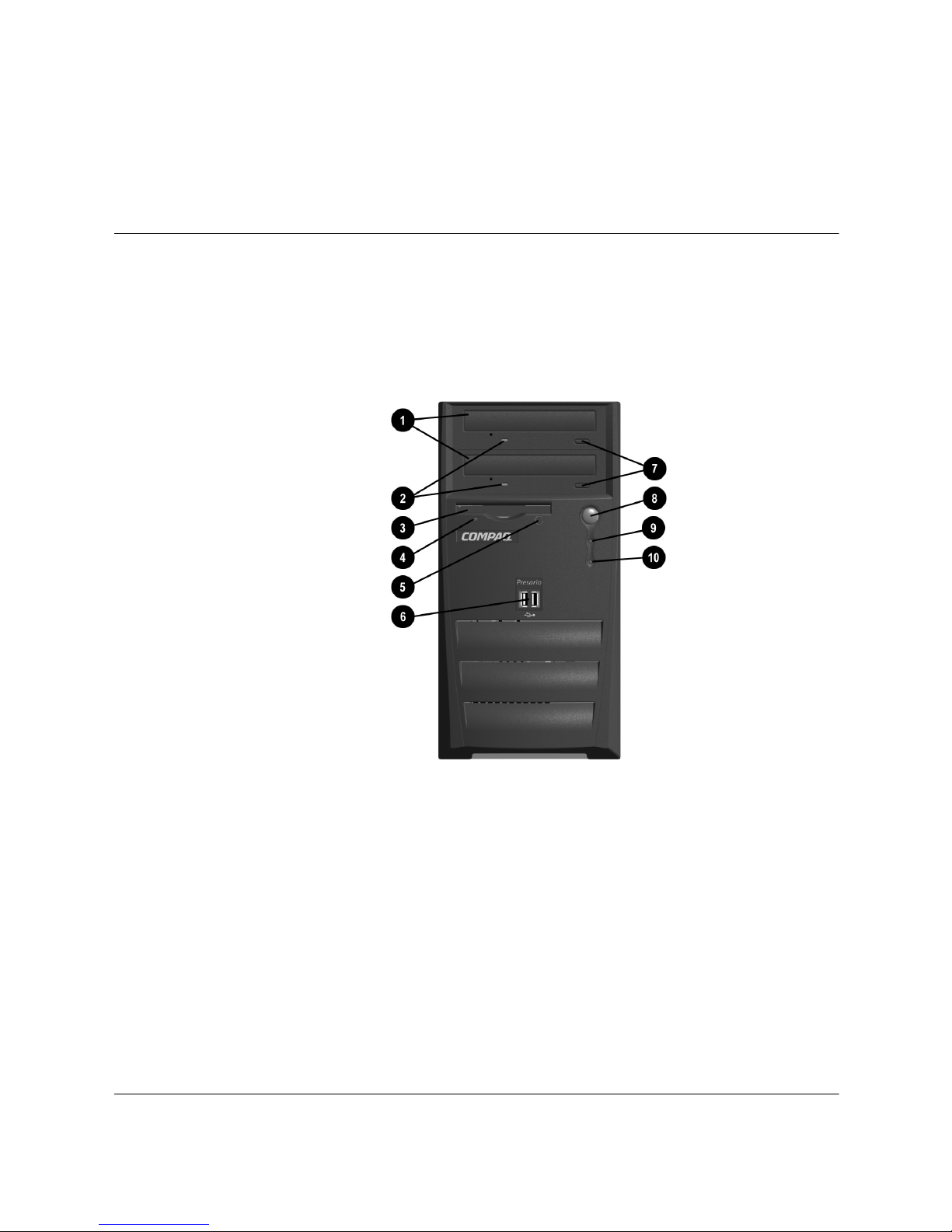
Front Panel Components
1
A Look at the Computer
Hardware Reference Guide 1–1
Page 6

A Look at the Computer
Front Panel Components
1 Optical drives Depending on your computer model, may be
a CD-ROM, CD-RW, or DVD-ROM drive. If a
second optical drive is not installed, it is
replaced by a removable blank bezel panel.
2 Optical drive activity lights When lit, indicates the optical drive is being
accessed.
3 Diskette drive Reads and writes information onto a 3.5-inch
diskette.
4 Diskette drive activity light When lit, indicates the diskette drive is being
accessed (Do not remove the diskette while
the light is on).
5 Diskette eject button Ejects the diskette from the diskette drive.
6 USB (Universal Serial Bus) ports
(available on select models)
7 Optical drive eject buttons Releases the optical drive disc tray.
8 Power button Turns on the computer. To turn off the
9 Power-on light When lit, indicates power is on.
: Hard drive activity light When lit, indicates the hard drive is being
Arrangement and number of drives and connectors may vary by model.
✎
Connects USB devices, such as gamepads,
joysticks and video cameras.
computer, use the operating system “Turn Off
Computer” command.
accessed.
1–2 Hardware Reference Guide
Page 7
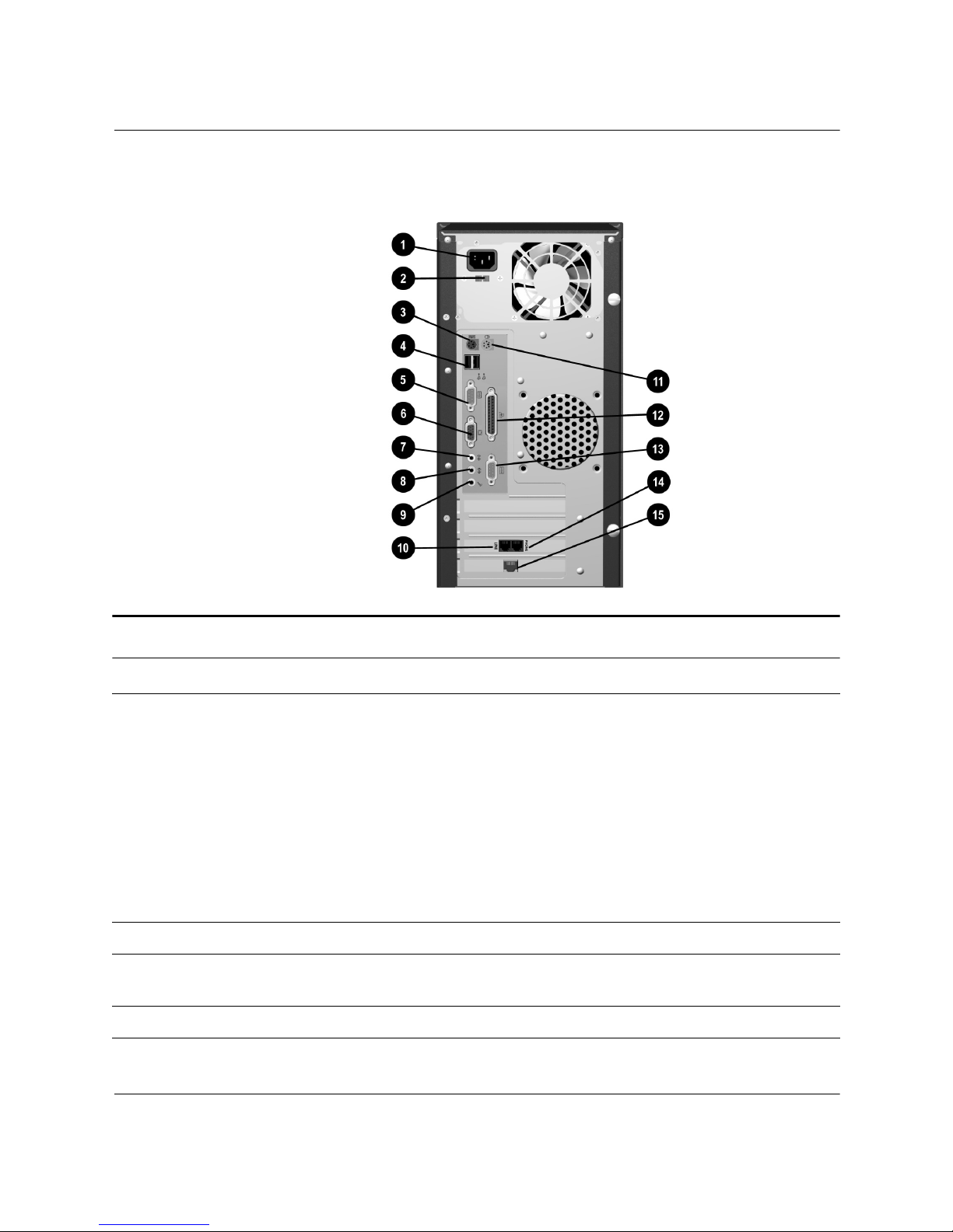
Rear Panel Components
A Look at the Computer
Rear Panel Components
1 Power cord connector Connects the computer’s power cord.
2 Voltage select switch (available on
select models)
3 PS/2 keyboard connector Connects a PS/2-compatible keyboard.
4 USB (Universal Serial Bus) ports Connects USB devices, such as a USB
5 Serial port Connects a serial device, such as a scanner.
Selects 230 volts (for some areas of Asia,
Africa, Australia and Europe) or 115 volts
(for North America, South America, and
Japan). This switch may be factory set to
230 volts. Before plugging the power cord
into an electrical outlet, be sure the switch is
set to your regional requirements.
Failure to set the switch to the correct
Ä
regional voltage requirement may
damage your internal components.
keyboard, mouse, or pointing device.
Hardware Reference Guide 1–3
Page 8

A Look at the Computer
Rear Panel Components (Continued)
6 VGA connector Connects the monitor to the computer.
7 Audio line-out connector Connects stereo speakers.
8 Audio line-in connector Connects audio devices.
9 Microphone connector Connects a microphone.
: Modem port Connects the modem cable. A modem cable
is included with the computer.
; PS/2 mouse connector Connects a PS/2-compatible mouse or other
pointing device.
< Parallel port Connects a parallel device, such as a
printer.
= Second serial port Connects a serial device.
> Telephone extension (not available
in all countries)
t Network Interface Card (NIC
connector (available on select
models)
Arrangement and number of connectors may vary by model.
✎
Connects the telephone to the computer.
Connects an Ethernet network cable. A
network cable is not included with your
computer.
1–4 Hardware Reference Guide
Page 9
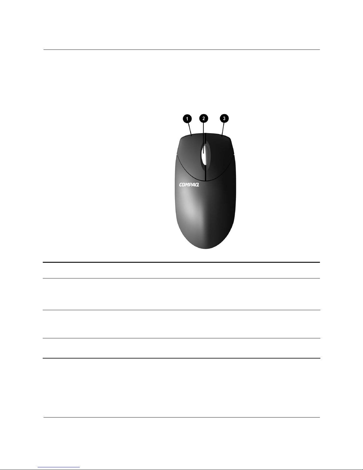
Mouse Components
Your computer includes a Scroll Mouse, a Wireless Wheel Mouse, or
a USB Optical Mouse. The Wireless Wheel Mouse and the USB
Optical Mouse are available with select models.
A Look at the Computer
Mouse Components
1 Left mouse button Click and quickly release to make screen selections.
Double-click and quickly release to open applications and
files.
2 Scroll wheel Moves the screen backward and forward through a
document without having to continuously move the mouse
or mouse wheel.
3 Right mouse button Click and quickly release to display application menu
selections.
Hardware Reference Guide 1–5
Page 10

A Look at the Computer
Using the Scroll Mouse
The mouse directs the cursor on the Windows desktop. Use the mouse
to move quickly and easily through a document or Web site.
Moving the scroll wheel on your mouse through a document or Web
site is faster than using the scroll bar. You can use the scroll wheel to:
■ Scroll forward or backward through a document or Web site by
turning the scroll wheel forward or backward.
■ Autoscroll by pressing down on the scroll wheel until it clicks
(you will see an autoscroll icon on your desktop). Move the
mouse vertically, horizontally, or diagonally to scroll in the
desired direction. The farther you move the cursor from the
starting point icon, the faster the scrolling occurs. To stop, press
the mouse button.
✎
Some mouse functions, such as autoscrolling, may not work with all
software.
Refer to the Learning More About Your Computer guide contained on
the Documentation Library CD for information on customizing your
mouse.
Using the Wireless Wheel Mouse
The wireless wheel mouse is available with select models. It has the
same features and functions as the scroll mouse with the addition of a
connect receiver box. Refer to the Getting Started guide included with
your computer for instructions on installing the batteries.
When using the wireless mouse:
■ Replace the batteries approximately every six months. The
wireless mouse does not alert you when the batteries are low.
■ For optimal performance, place the connect receiver box at least
8-inches/20-centimeters away from other electrical devices, such
as the computer, monitor or external storage equipment.
■ Refer to the “Solving Minor Problems” section in your
1–6 Hardware Reference Guide
Getting Started Guide if your wireless mouse does not function
properly.
Page 11

Using the USB Optical Mouse
The USB optical mouse is available with select models. It provides
the same functions as the scroll mouse and wireless wheel mouse
except it uses an optical sensor instead of a mechanical ball to
determine the position of the cursor on the screen. The surface on
which you use the optical mouse plays an important role in tracking
the cursor. When using the optical mouse:
■ Use a mousepad or a white sheet of paper underneath your
mouse. Using it on a glass or see-through surface will inhibit the
ability of the sensor to track the cursor.
■ Avoid using the mouse on a reflective surface such as a mirror or
shiny metal desk. This may cause tracking problems.
■ Some wood grains and grooved surfaces may also cause tracking
problems.
■ Refer to the “Solving Minor Problems” section in your
Getting Started Guide if your optical mouse does not function
properly.
A Look at the Computer
Hardware Reference Guide 1–7
Page 12
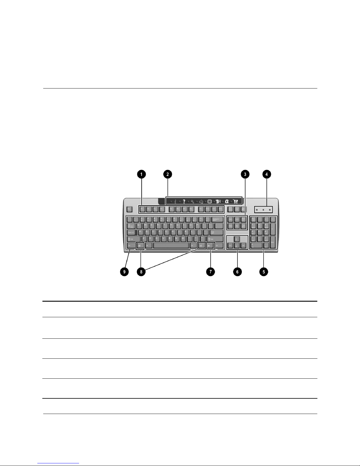
Keyboard Features
Easy Access Keyboard Components
2
Easy Access Keyboard Components
1 Function keys Perform special functions, depending on the software
2 Easy Access Buttons Provide quick access to your favorite Web sites, services,
3 Edit keys Includes the following: Insert, Home, Page Up, Delete,
4 Status Lights Indicates a quick status of your computer and keyboard
Hardware Reference Guide 2–1
application being used.
and applications.
End, and Page Down.
settings (Num Lock, Caps Lock, and Scroll Lock).
Page 13

Keyboard Features
Easy Access Keyboard Components (Continued)
5 Numeric Keys Works like a calculator keypad.
6 Arrow Keys Navigates through games or through a document or Web
site. These keys allow you to move left, right, up, and
down, using the keyboard instead of the mouse.
7 Application Key* Opens (used like the right mouse button) pop-up menus in
a Microsoft Office application. May perform other functions
in other software applications.
8 Windows Logo Keys* Opens the Start menu in Microsoft Windows. Used in
combination with other keys to perform other functions.
9 Main Keys Works like standard typewriter-style keys.
* Keys available in select geographic regions.
Using the Easy Access Buttons
The Easy Access Buttons make accessing your favorite Web sites,
services, and applications easier and faster.
✎
Several Easy Access Buttons are programmed to default to an
Internet Web site. However, until you set up your Internet Service
Provider (ISP), the buttons will take you to a window that guides you
through the ISP setup process.
2–2 Hardware Reference Guide
Page 14

Keyboard Features
Easy Access Buttons
1 Instant Internet Provides your daily starting point to the Internet. It
connects you to a customizable Web page filled with
local weather, news, sports, and financial information.
2 Help Takes you to the Compaq Help & Support center, which
provides information about your computer. You can find
information about your computer and computer-related
peripherals as well as access links to online technical
support.
3 Search Accesses a Web site that helps you locate news and
information on the Internet. Search for topics including
news and information, shopping, graphics, music, and
video.
4 E-mail Launches your e-mail application.
Hardware Reference Guide 2–3
Page 15
Keyboard Features
Easy Access Buttons (Continued)
5 Smart Card
or
Community
6 Entertainment Your online connection to the world of entertainment,
7 My Compaq PC Takes you to the My Presario Web site.
8 Retail/Affinity
Central
Easy Access Button functions may vary by model and by region.
✎
Depending on your region, this button launches the
Smart Card of Compaq online Community.
• The Smart Card button is available on U.S. English
keyboards. When pressed, it provides information
on obtaining a Smart Card and shopping at
participating online merchants.
• The Community button provides online collaboration
between novice and technical experts, who share
knowledge and information and provide assistance.
Participate in existing product discussions, review
commonly asked questions and answer or post new
questions to a community of users.
featuring music downloads, streaming video, Web
casts, entertainment news, and reviews.
Provides an instant connection to your computer store
and a variety of leading consumer companies.
Customizing the Easy Access Buttons
All Easy Access Buttons can be reprogrammed to open any software
application or data file on your hard drive, or any Internet address.
To reprogram the Easy Access Buttons, complete the following steps:
1. Double-click the keyboard icon in the notification area (lower
right corner) of the Windows taskbar. The Keyboard Properties
dialog box is displayed.
2. Click the Help button on the keyboard properties dialog box for
instructions.
2–4 Hardware Reference Guide
Page 16

Keyboard Features
Using the Windows Logo Key
Use the Windows Logo key in combination with other keys to
perform certain functions available in the Windows operating system.
Refer to “Easy Access Keyboard Components” in this chapter to
identify the Windows Logo key.
Windows Logo Key + F1 Displays a pop-up menu for the selected object
Windows Logo Key + Tab Activates the next Taskbar button
Windows Logo Key + e Launches Explore My Computer
Windows Logo Key + f Launches Find Document
Windows Logo Key + Ctrl + f Launches Find Computer
Windows Logo Key + m Minimizes all open applications
Shift + Windows Logo Key + m Undoes Minimize All
Windows Logo Key + r Displays the Run dialog box
Hardware Reference Guide 2–5
Page 17
Keyboard Features
Identifying System Status Lights
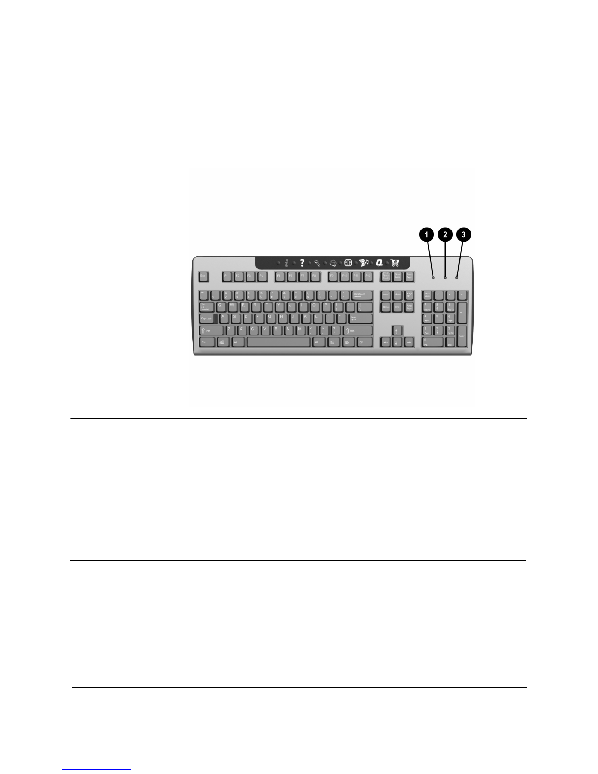
The system lights on the keyboard provide a quick status of your
computer and keyboard settings.
System Status Lights
1 Num Lock When lit, the Num lock is on and indicates that you can
use the numeric key pad to type numbers.
2 Caps Lock When lit, the Caps lock is on and indicates all text typed
will appear as capital letters.
3 Scroll Lock When lit, the Scroll lock is on and indicates when the
scroll-lock function is engaged, enabling you to scroll
through a document without moving the cursor.
2–6 Hardware Reference Guide
Page 18

You can replace or upgrade several components in your computer.
This chapter provides procedures on accessing and installing the
internal parts of the computer.
Preparing the Computer
CAUTION: Static electricity can damage the electronic components of
Ä
the computer or optional equipment. Before beginning these
procedures, ensure that you are discharged of static electricity by briefly
touching a grounded metal object. Refer to “Appendix A” in this guide for
additional information on preventing electrostatic discharge.
1. Remove any diskette or compact discs (CDs) from the computer.
3
Computer Upgrades
2. To shut down the computer, click the Start button, and then click
Turn Off Computer. The Turn Off Computer dialog box is
displayed. Select Turn O ff to turn the computer off.
Hardware Reference Guide 3–1
Page 19
Computer Upgrades
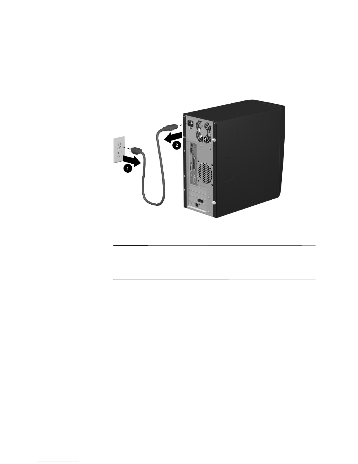
3. Disconnect the power cord from the electrical outlet 1 and then
from the computer 2.
Å
Disconnecting the Power Cord
WARNING: To reduce the risk of personal injury from electrical shock
and/or hot surfaces, be sure to disconnect the power cord from the wall
outlet, and allow the internal system components to cool before
touching.
4. Disconnect all external devices connected to the computer.
3–2 Hardware Reference Guide
Page 20
Computer Upgrades
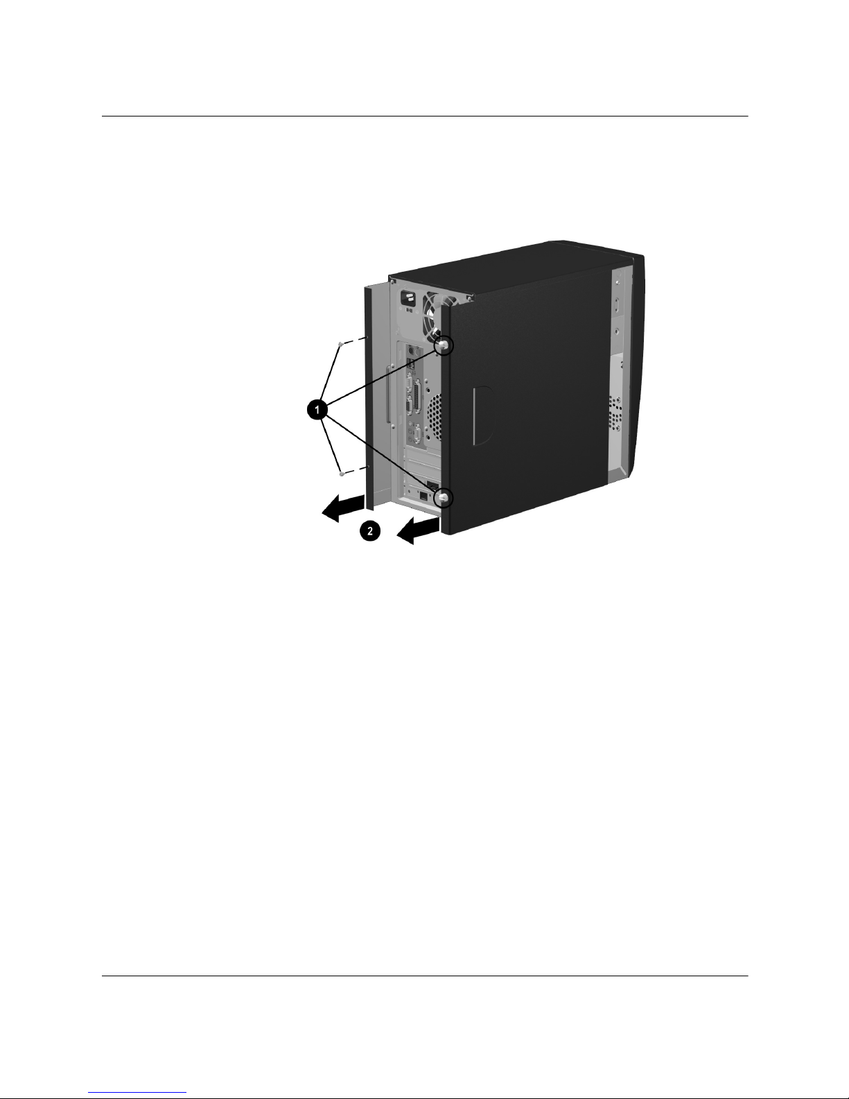
5. Remove the access panels by loosening the screws 1 that secure
the access panels to the computer chassis. Slide the access panels
back 2 from the unit.
Removing the Computer Access Panels
Hardware Reference Guide 3–3
Page 21
Computer Upgrades
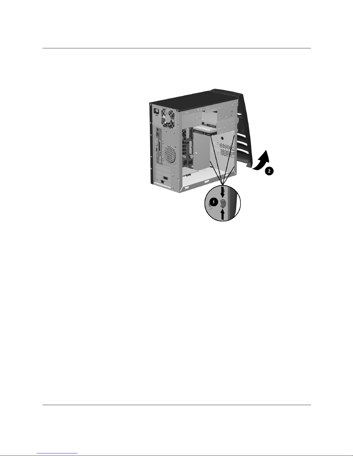
6. Remove the front bezel by pressing the release tabs 1, then
rotating the front bezel away from the chassis to release it 2.
Removing the Front Bezel
3–4 Hardware Reference Guide
Page 22

Removing or Upgrading a Drive
Depending on your computer configuration, you may have up to four
of the following storage drives in your computer.
■ CD-ROM or CD-RW drive
■ DVD-ROM drive
■ Hard drive
■ Diskette drive
This section provides the procedure on replacing or upgrading your
storage drives. You will need a Torx or Flathead screwdriver to
remove or replace a drive.
CAUTION: Make sure you backup your personal files on the hard drive
to an external storage device, such as a CD, before removing the hard
drive. Failure to do so will result in data loss. After replacing the hard
drive, you will need to run the Compaq Restore Plus! CD to load the
Compaq factory installed files.
Computer Upgrades
Hardware Reference Guide 3–5
Page 23
Computer Upgrades
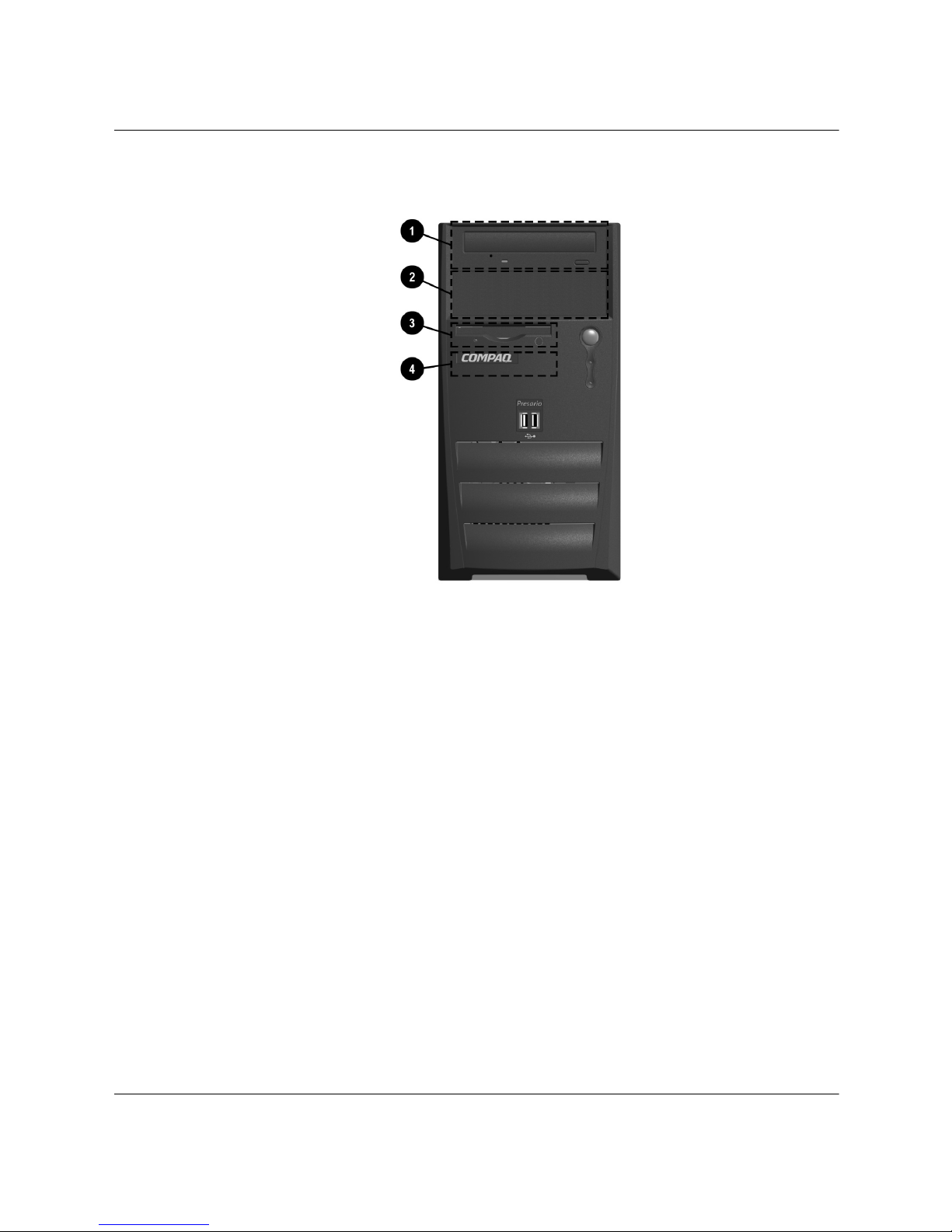
Locating Drive Positions
Drive Positions
1 Optical drive (may be a CD-ROM, CD-RW or DVD-ROM drive)
2 Second optical drive (may be a CD-ROM, CD-RW or DVD-ROM).
3 Diskette drive
4 Hard drive
Removing a Drive
If you do not have a second optical drive installed, a blank bezel
panel is provided.
1. Locate the drive you want to remove. Refer to the previous
section in this chapter on “Locating Drive Positions” for details.
2. Complete the procedure described in “Preparing the Computer”
at the beginning of this chapter.
3–6 Hardware Reference Guide
Page 24
Computer Upgrades
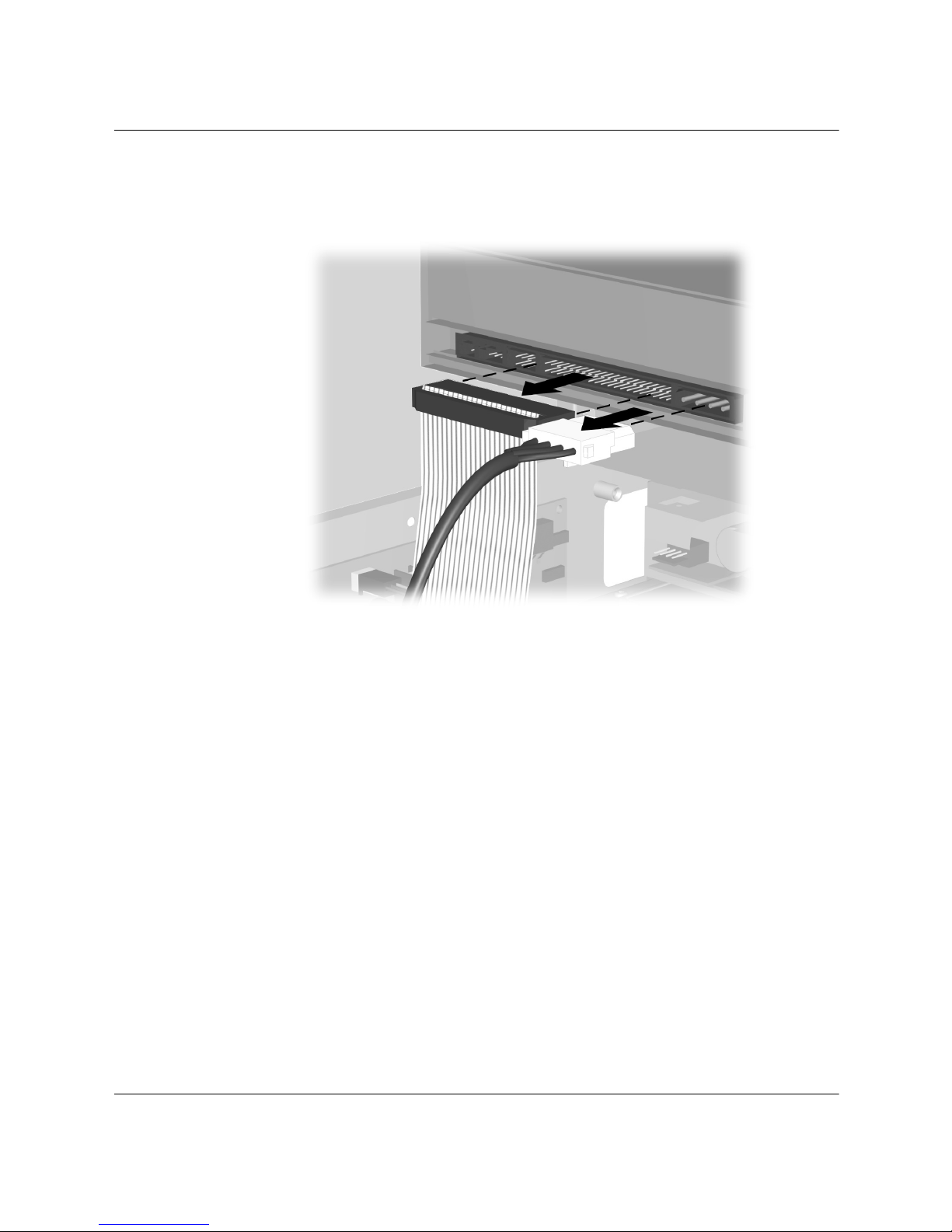
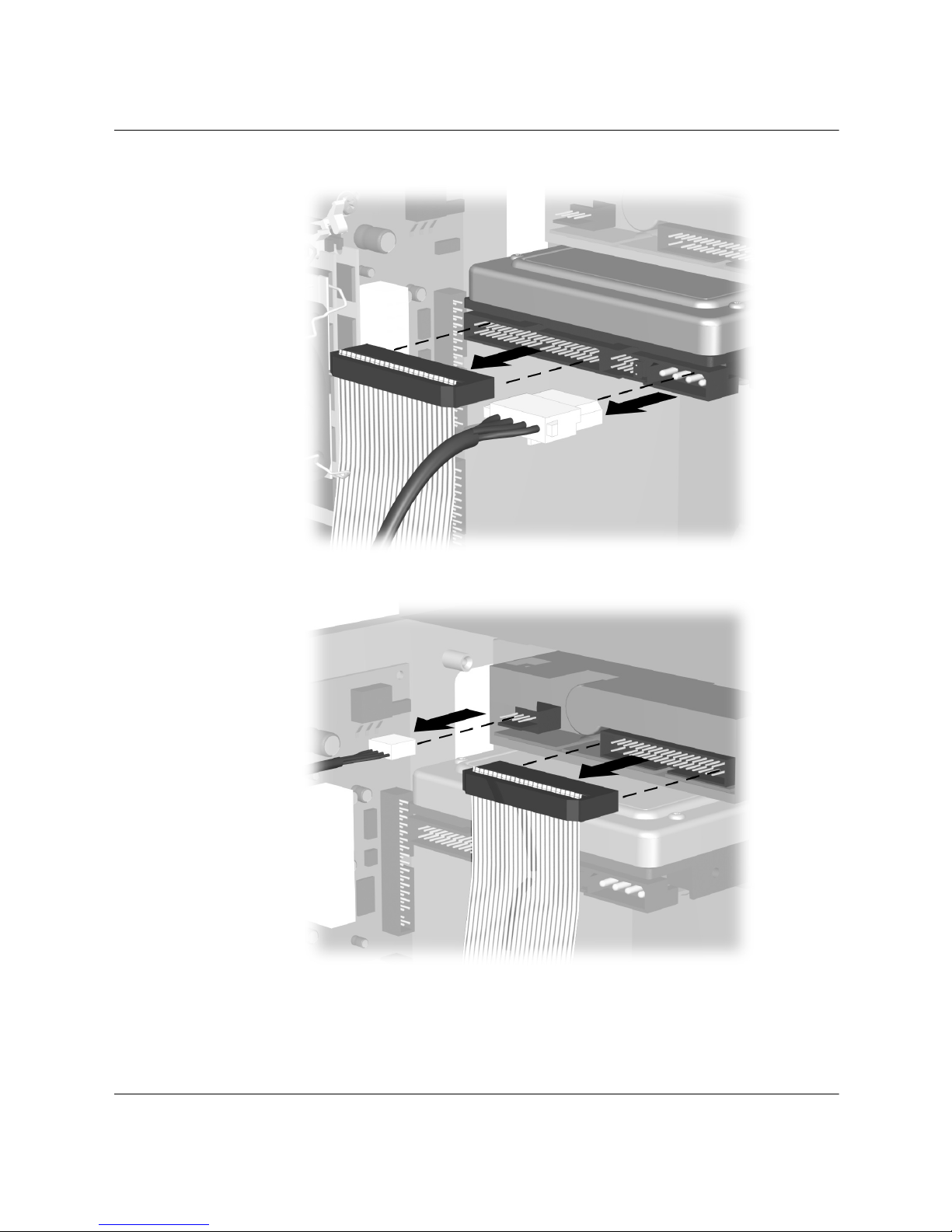
3. Disconnect the power and data cables from the back of the drive
you want to remove as indicated in the following illustrations.
Disconnecting the Optical Drive Cables
Hardware Reference Guide 3–7
Page 25
Computer Upgrades
Disconnecting the Hard Drive Cables
Disconnecting the Diskette Drive Cables
3–8 Hardware Reference Guide
Page 26
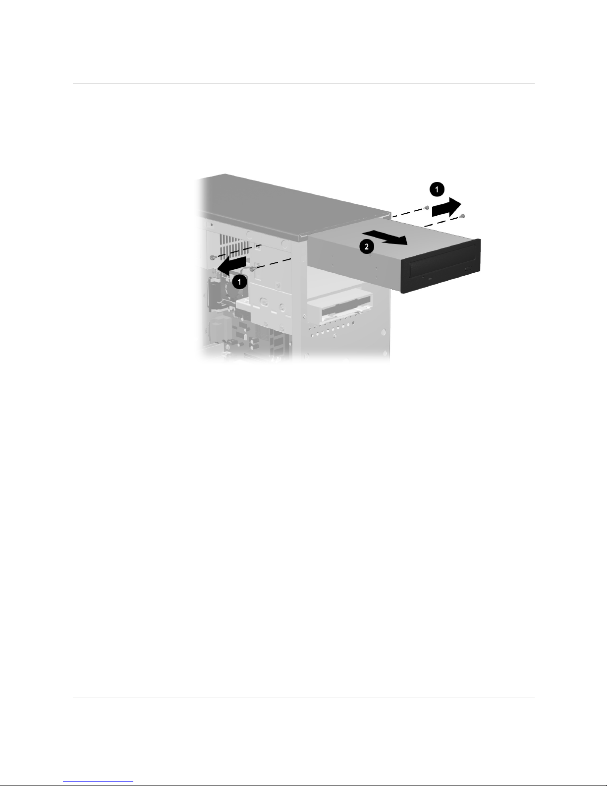
Computer Upgrades
4. If you are removing an optical drive, remove the four screws 1,
two from each side, that connect the drive to the chassis, then
slide the drive out of the chassis 2.
Removing an Optical Drive
Hardware Reference Guide 3–9
Page 27
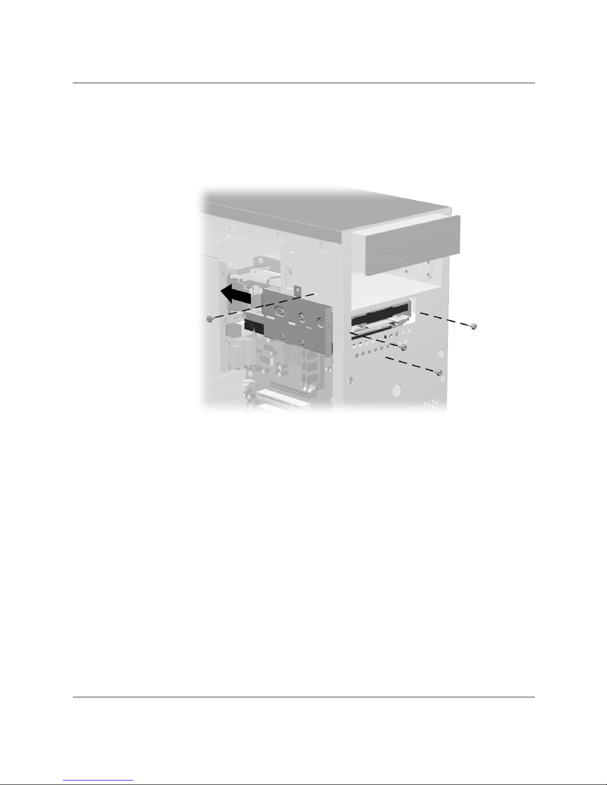
Computer Upgrades
5. The diskette drive and hard drive are enclosed in a drive cage. If
you are removing a hard drive or diskette drive, remove the
four screws from the drive cage, then slide the drive cage back,
toward the rear, and out of the chassis.
Removing the Drive Cage
3–10 Hardware Reference Guide
Page 28
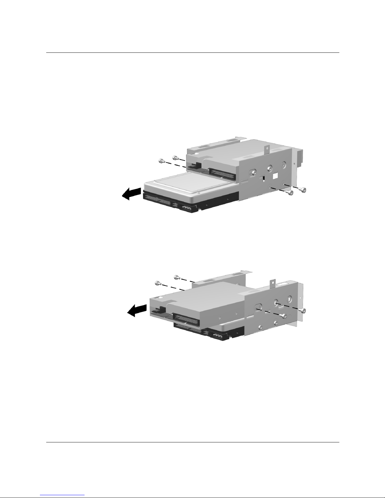
Computer Upgrades
6. Place the drive cage on a flat working surface. Remove the four
screws, two on each side, securing the drive to the drive cage.
Slide the drive from the drive cage as indicated in the following
illustrations.
Removing the Hard Drive from the Drive Cage
Removing the Diskette Drive from the Drive Cage
Hardware Reference Guide 3–11
Page 29
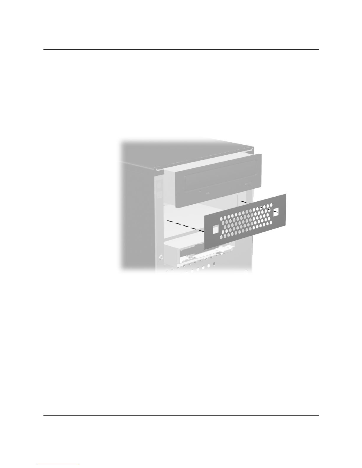
Computer Upgrades
Replacing or Adding a Drive
1. Follow the procedures described in “Preparing the Computer”
and “Removing A Drive,” sections at the beginning of this
chapter.
2. If you are adding a drive to an empty drive bay, remove the metal
break away plate from the chassis.
Removing the Metal Plate
3–12 Hardware Reference Guide
Page 30
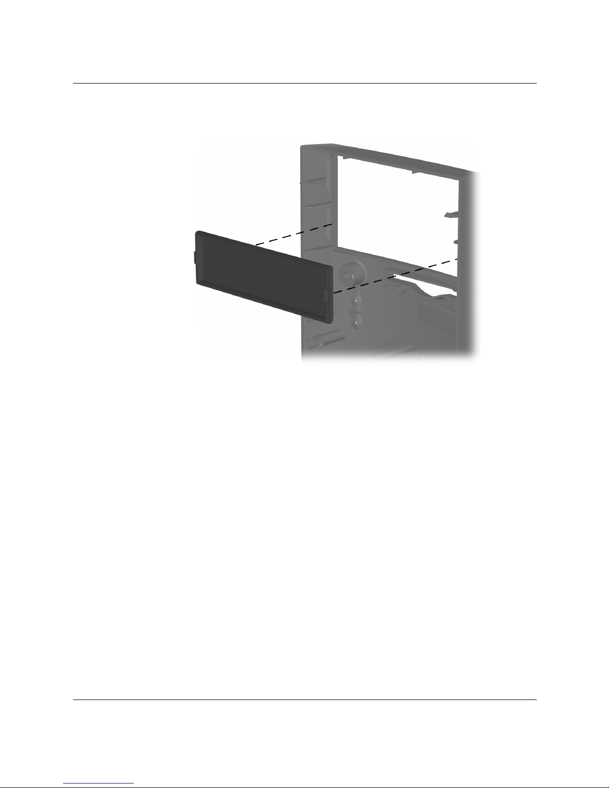
Computer Upgrades
3. Remove the blank bezel from the front panel bezel.
Removing a Blank Bezel
Hardware Reference Guide 3–13
Page 31
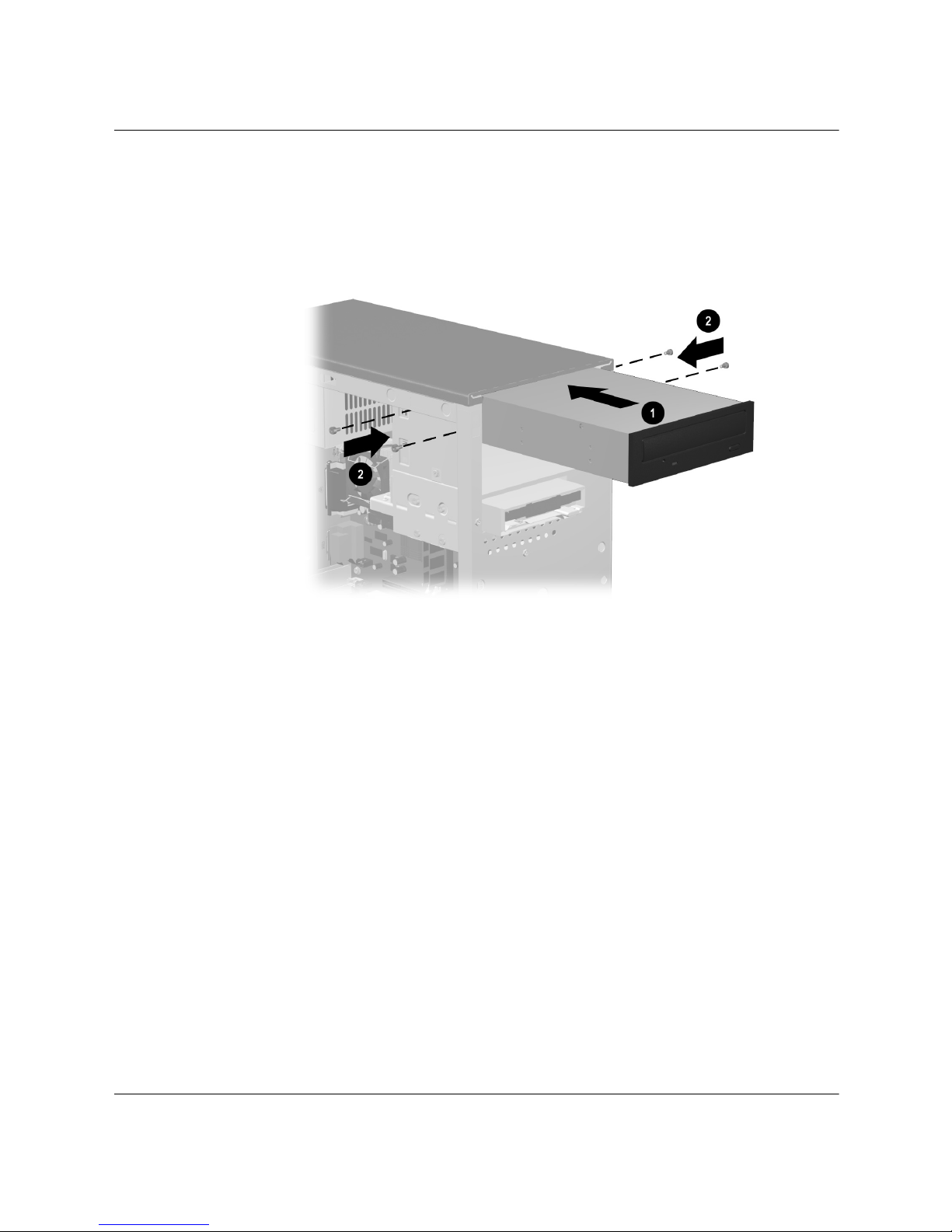
Computer Upgrades
4. If you are installing an optical drive, slide the drive into the
chassis 1, then install the four screws, two on each side, to secure
the drive to the chassis 2.
Installing the New Optical Drive
3–14 Hardware Reference Guide
Page 32
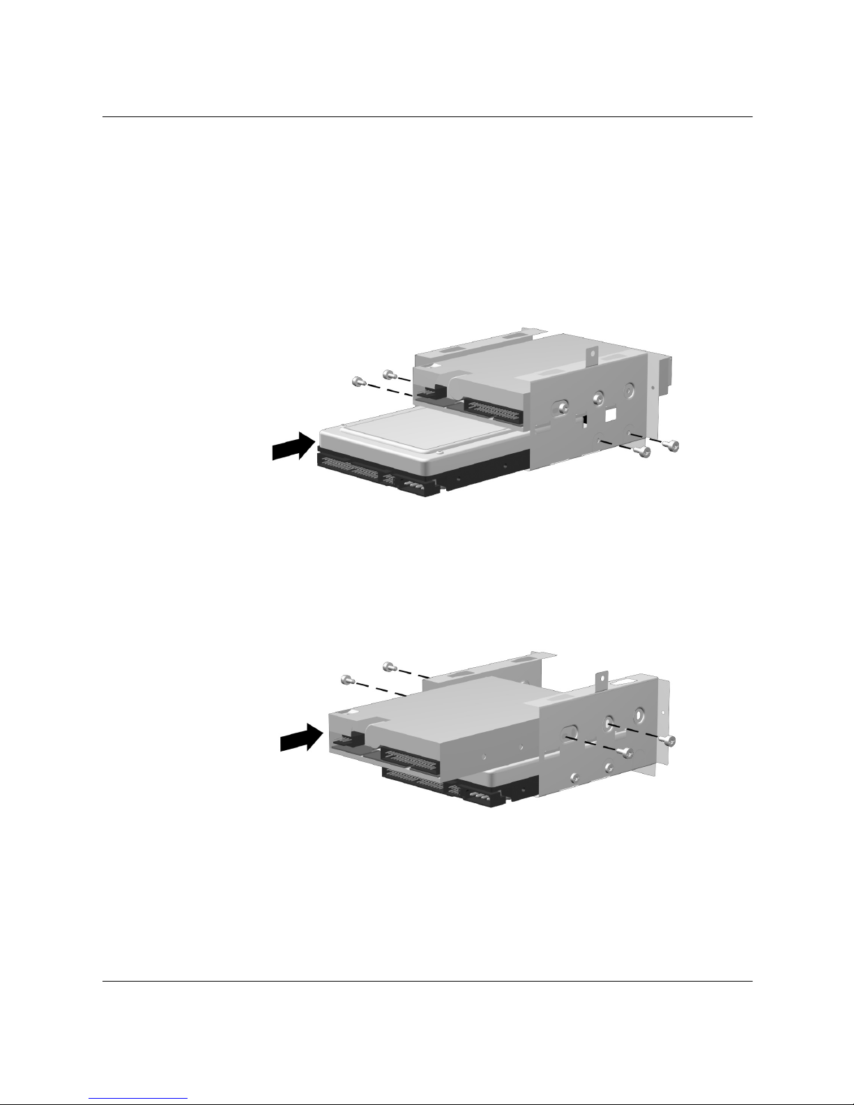
Computer Upgrades
5. If you are installing a hard drive or diskette drive, insert the
drive into the drive cage as indicated in the following
illustrations. Reinstall the screws (two on each side) that secure
the drive to the drive cage.
Installing the New Hard Drive in the Drive Cage
Installing the New Diskette Drive in the Drive Cage
Hardware Reference Guide 3–15
Page 33
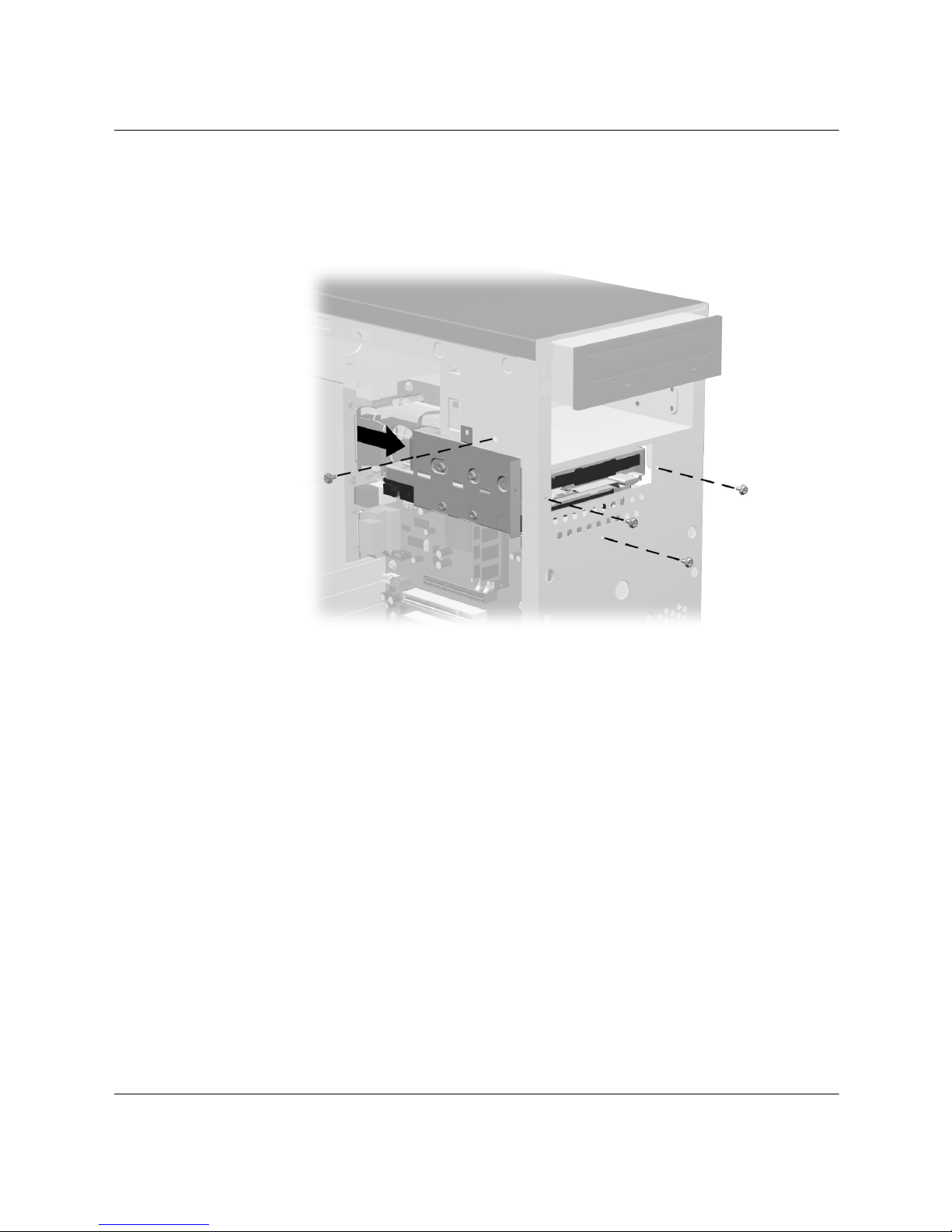
Computer Upgrades
6. Replace the drive cage inside the chassis by sliding it toward the
front of the chassis into position. Reinstall the screws to secure
the cage to the chassis.
Replacing the Drive Cage
3–16 Hardware Reference Guide
Page 34
Computer Upgrades
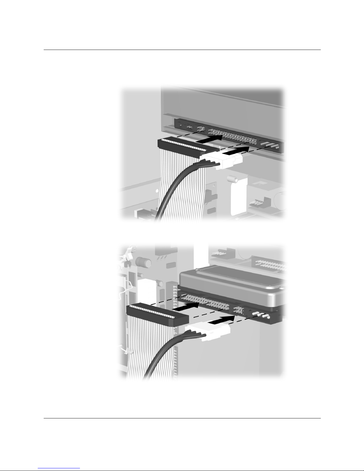
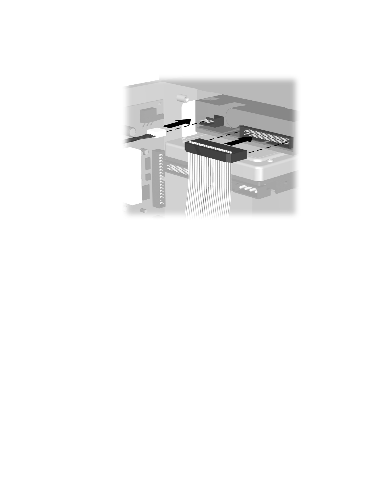
7. Reconnect the power and data cables to your drive.
Reconnecting the Optical Drive Cables
Reconnecting the Hard Drive Cables
Hardware Reference Guide 3–17
Page 35
Computer Upgrades
Reconnecting the Diskette Drive Cables
8. Complete the procedure described in “Reassembling the
Computer” section of this chapter.
9. Turn on the computer.
10. If you replaced the hard drive insert the Compaq Restore Plus!
CD to restore the operating system, software drivers, and/or any
software applications that were preinstalled on the computer from
Compaq. Follow the instructions in the guide included with the
restore CD. When the restore process is completed, reinstall your
personal files that you backed up before replacing your hard
drive.
Upgrading or Replacing Memory
Your computer comes with random access memory (RAM), which
temporarily stores data and instructions on your computer. Memory
expansion modules can be installed in the memory expansion slots in
the computer.
3–18 Hardware Reference Guide
Page 36
There are several different types of memory modules. Install the same
type of memory currently in your computer. To find your type of
memory, go to the compaq.com/athome/memory Web site.
No tools are needed to remove, replace, or upgrade memory modules.
Removing a Memory Module
CAUTION: When handling a memory module, be careful not to touch
Ä
any of the contacts. Doing so may damage the module.
1. Complete the procedure described in “Preparing the Computer”
section at the beginning of the chapter, but do not remove the
front bezel.
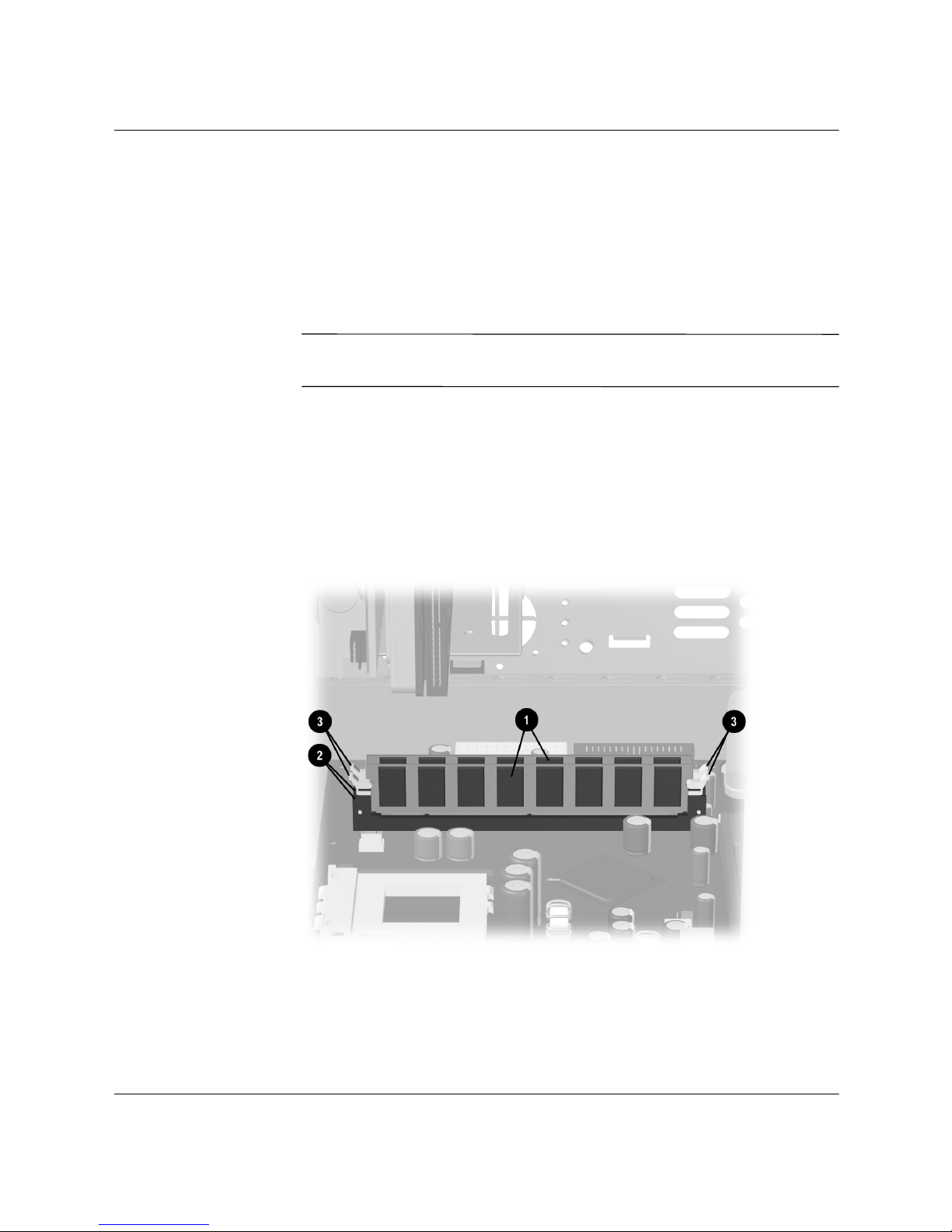
2. Locate the memory module inside your computer. See the
following illustration for the location of the memory modules 1,
memory slots 2 and release latches 3 on the system board.
Computer Upgrades
Locating the Memory Module
Hardware Reference Guide 3–19
Page 37
Computer Upgrades
✎
The location and number of memory modules may vary slightly by
model.
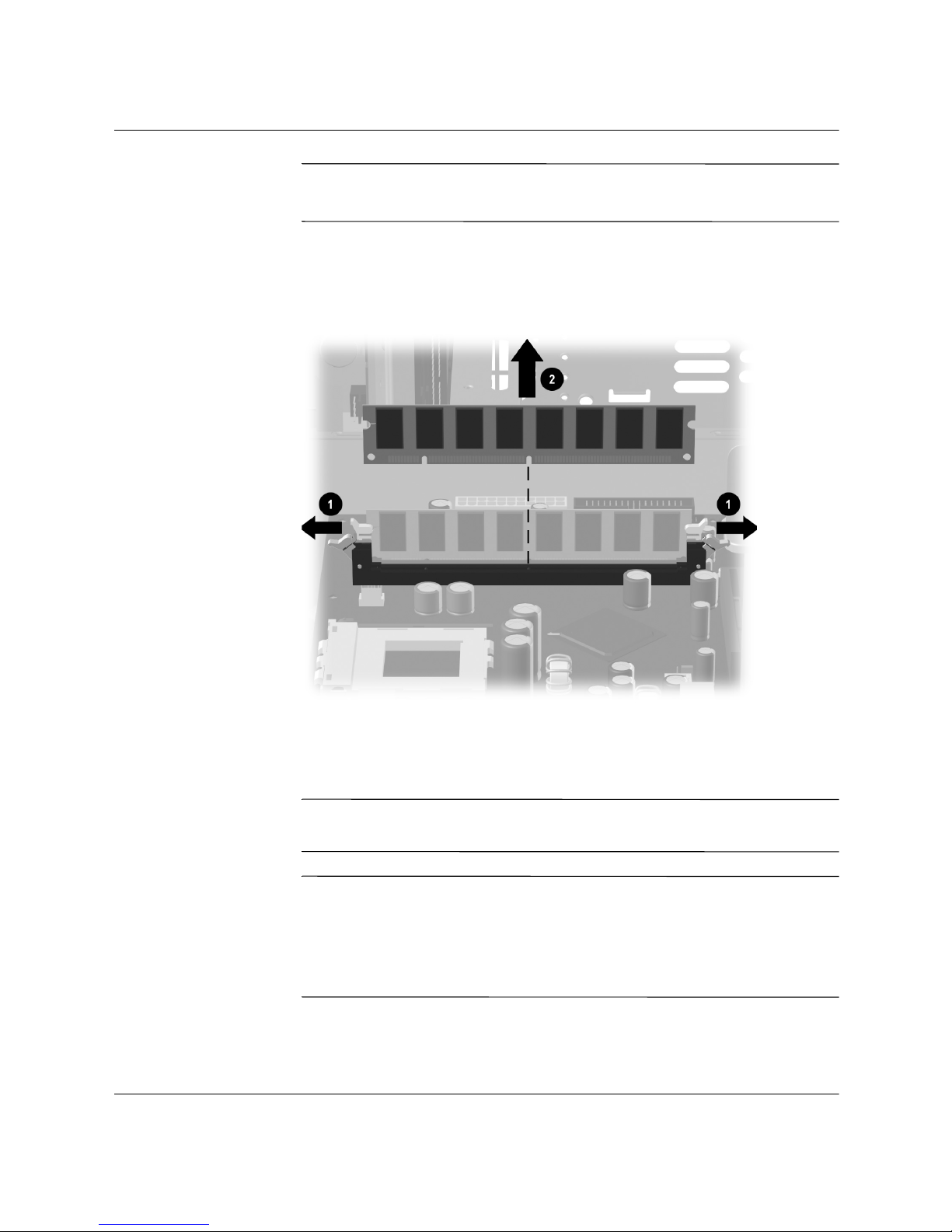
3. Open both latches of the memory module socket 1 found at each
end of the memory module. Lift the memory module 2 from the
memory slot.
Removing a Memory Module
Replacing or Adding a Memory Module
CAUTION: When handling a memory module, be careful not to touch
Ä
✎
3–20 Hardware Reference Guide
any of the contacts. Doing so may damage the module.
Upgrade the memory in your computer with memory of the same type
and speed to the memory originally installed in your computer. You
can find out exactly what type of memory is in your computer at the
compaq.com/athome/memory Web site (not available in all
languages).
Page 38
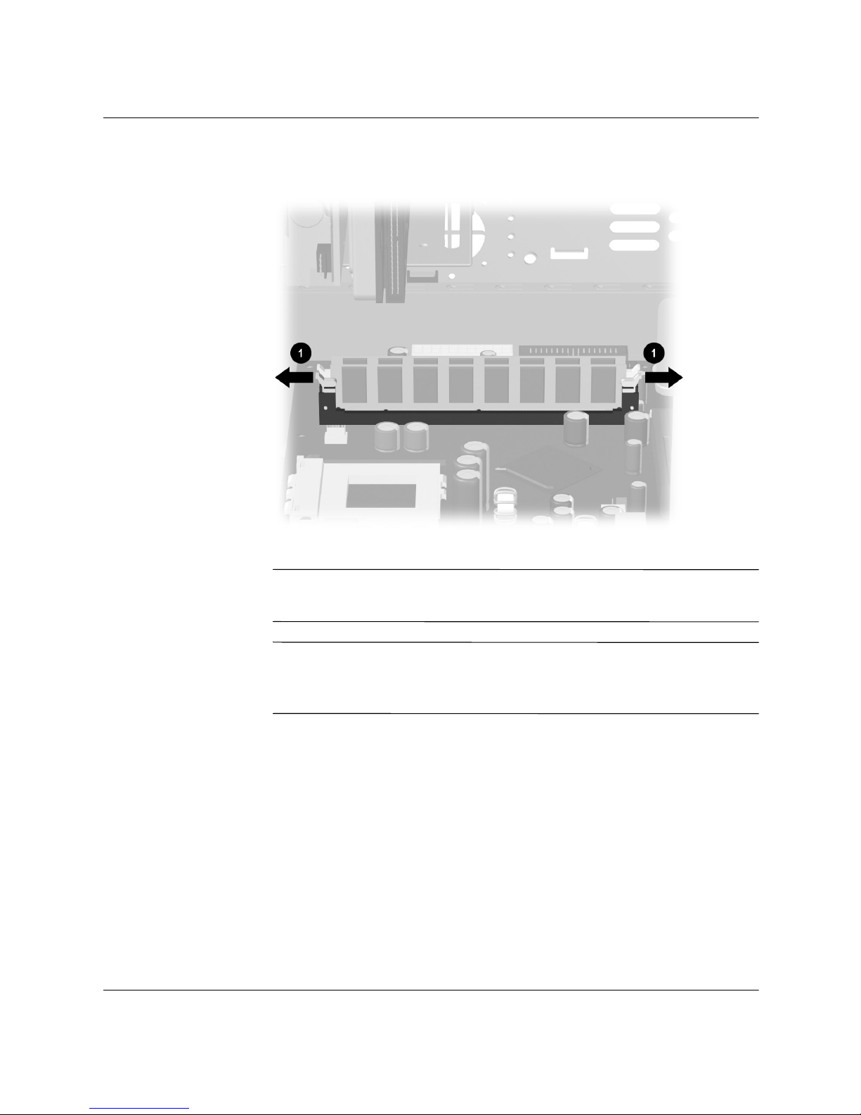
Computer Upgrades
1. Open both latches of the memory module socket.
✎
✎
Opening the Latches on the Memory Module Socket
If you are replacing a memory module, put the new memory module
in the same memory slot from which the old memory was removed.
If you are adding a memory module, install the new module into the
socket nearest the preinstalled module, and install additional modules
in the next available sockets.
Hardware Reference Guide 3–21
Page 39
Computer Upgrades
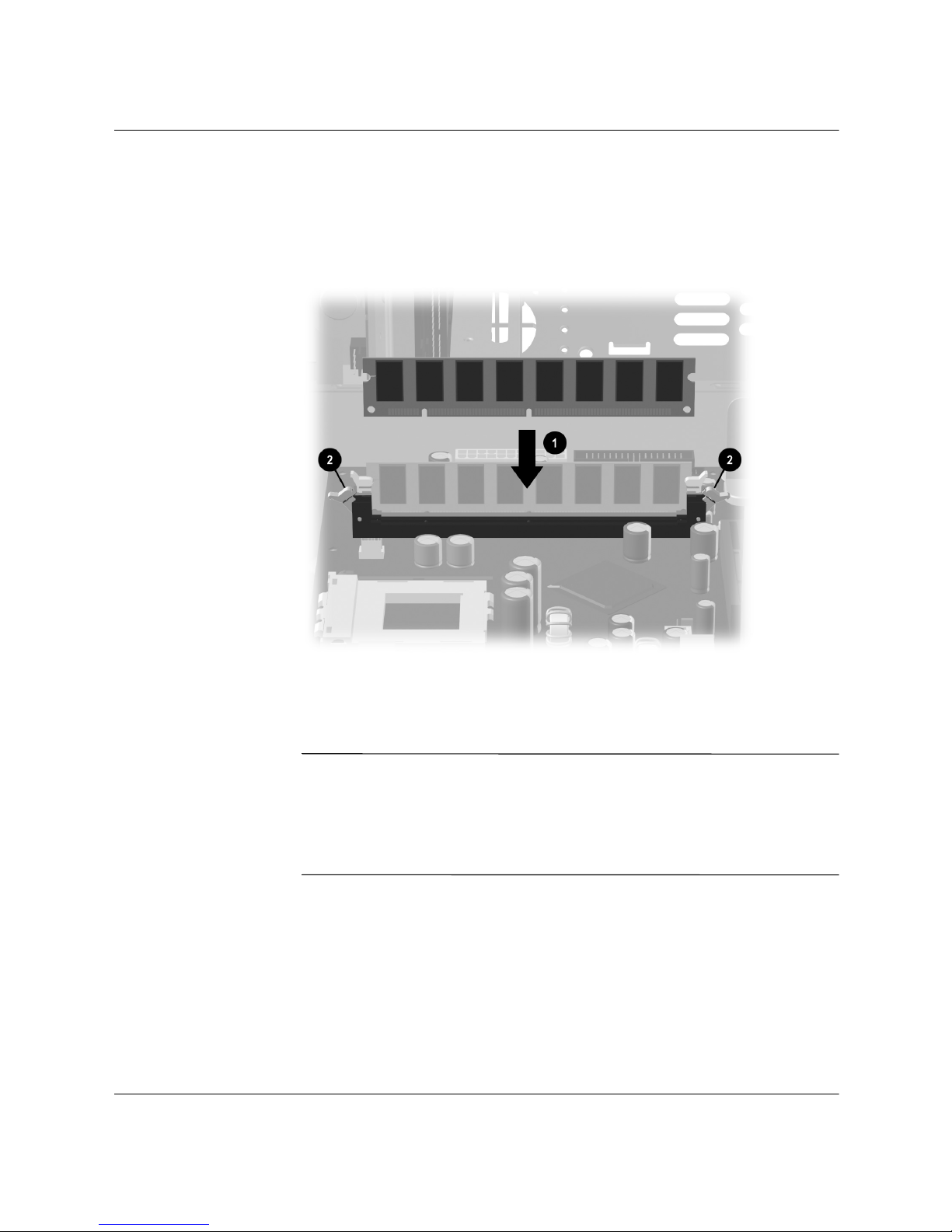
2. The memory module can be installed in only one way. Match the
notch on the module 1 with the tab on the memory socket. Push
the module carefully and firmly into the slot ensuring that the
latches on both ends snap into place.
Installing a Memory Module
3. Complete the procedure described in “Reassembling the
Computer” section of this chapter.
✎
3–22 Hardware Reference Guide
If a blank screen is displayed after replacing or adding a memory
module, the memory is installed incorrectly or it is the wrong type of
memory. Remove and reinstall the memory modeuls as previously
described in the “Replacing or Adding a Memory Module” section of
this chapter.
Page 40

Removing or Installing an Expansion Card
An expansion card is a circuit board that fits into a computer
expansion slot. Your computer contains several expansion slots that
can be used to add components to your computer.
Expansion cards you can add to your computer include:
■ Modem
■ Network Interface Card (NIC)
■ Graphics Card
■ Sound Card
A Phillips screwdriver is needed to remove, replace, or add an
expansion card.
1. Complete the procedure described in “Preparing the Computer”
section at the beginning of this chapter, but do not remove the
front bezel.
Computer Upgrades
2. Inside the computer, locate the expansion slots on the system
board.
Hardware Reference Guide 3–23
Page 41
Computer Upgrades
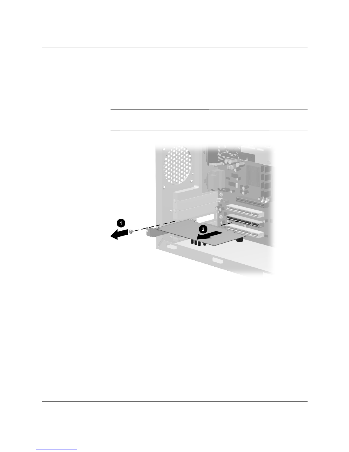
3. If you are removing an existing expansion card, remove the
screw 1 at the top of the expansion slot. Holding the card at each
end, carefully rock it back and forth until the connectors pull free
from the socket 2. Be sure not to scrape the card against the other
components.
✎
Keep the screw that secures the expansion slot cover to the chassis.
You will need it when installing the new card.
Removing an Expansion Card
4. If you are not replacing the old expansion card with a new
3–24 Hardware Reference Guide
expansion card, install an expansion slot cover to close the open
slot. Insert the metal slot cover in the opened slot and install a
screw to to the top of the cover to secure it in place.
Page 42
Computer Upgrades
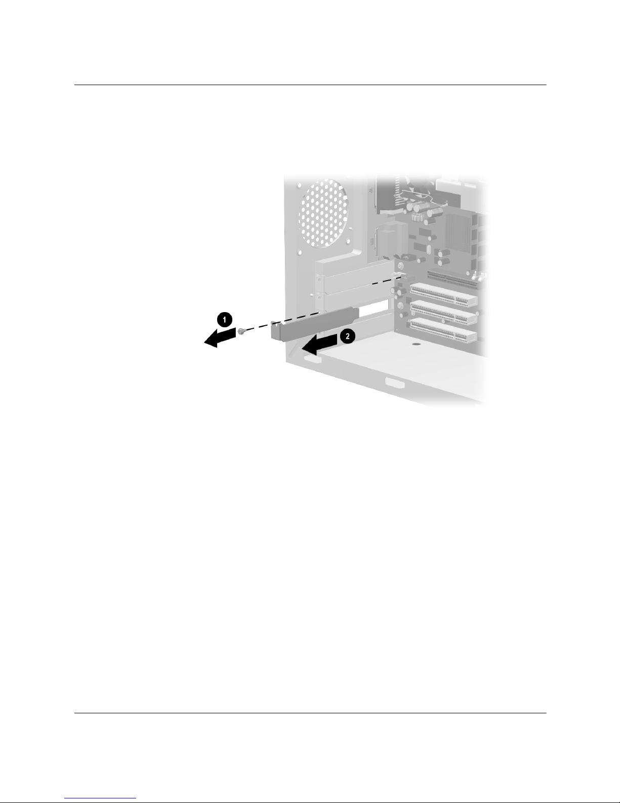
5. If you are adding a new expansion card to the computer, remove
the screw 1 securing the slot cover, then remove the expansion
slot cover 2 from the slot.
Removing the Screw and Expansion Slot Cover
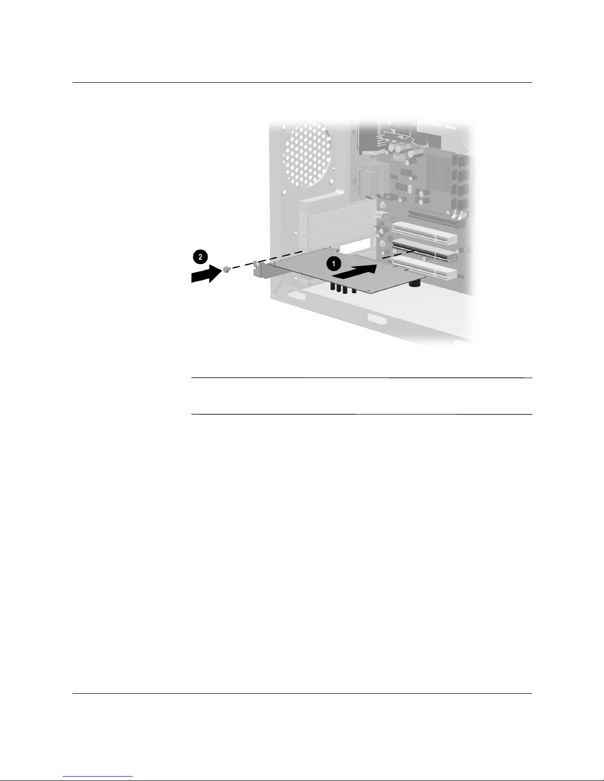
6. Add or replace an expansion card to a slot by aligning the edge of
the expansion card with the slot on the chassis and gently
pressing the card straight down into the expansion slot 1.
Reinstall the screw that secures the card to the chassis 2.
7. If you have replaced or added a new expansion card, store the old
card in the anti-static packaging that contained your new card.
Hardware Reference Guide 3–25
Page 43
Computer Upgrades
✎
Replacing or Adding an Expansion Card
When you install an expansion card, press firmly on the card so that
the whole connector seats properly in the expansion card slot.
8. Complete the procedure described in “Reassembling the
Computer” section of this chapter.
3–26 Hardware Reference Guide
Page 44
Reassembling the Computer
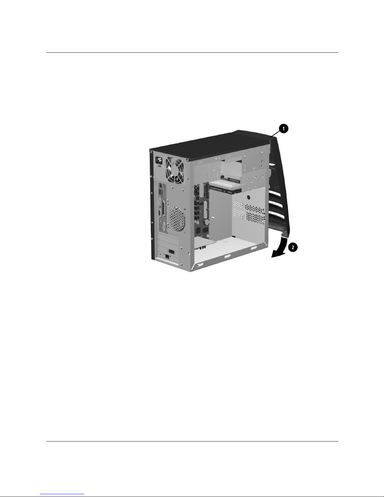
1. Place the front bezel in the correct position. Ensure the slots 1
are aligned correctly and rotate the bezel toward the chassis 2
until it snaps into place.
Computer Upgrades
Replacing the Front Bezel
Hardware Reference Guide 3–27
Page 45
Computer Upgrades
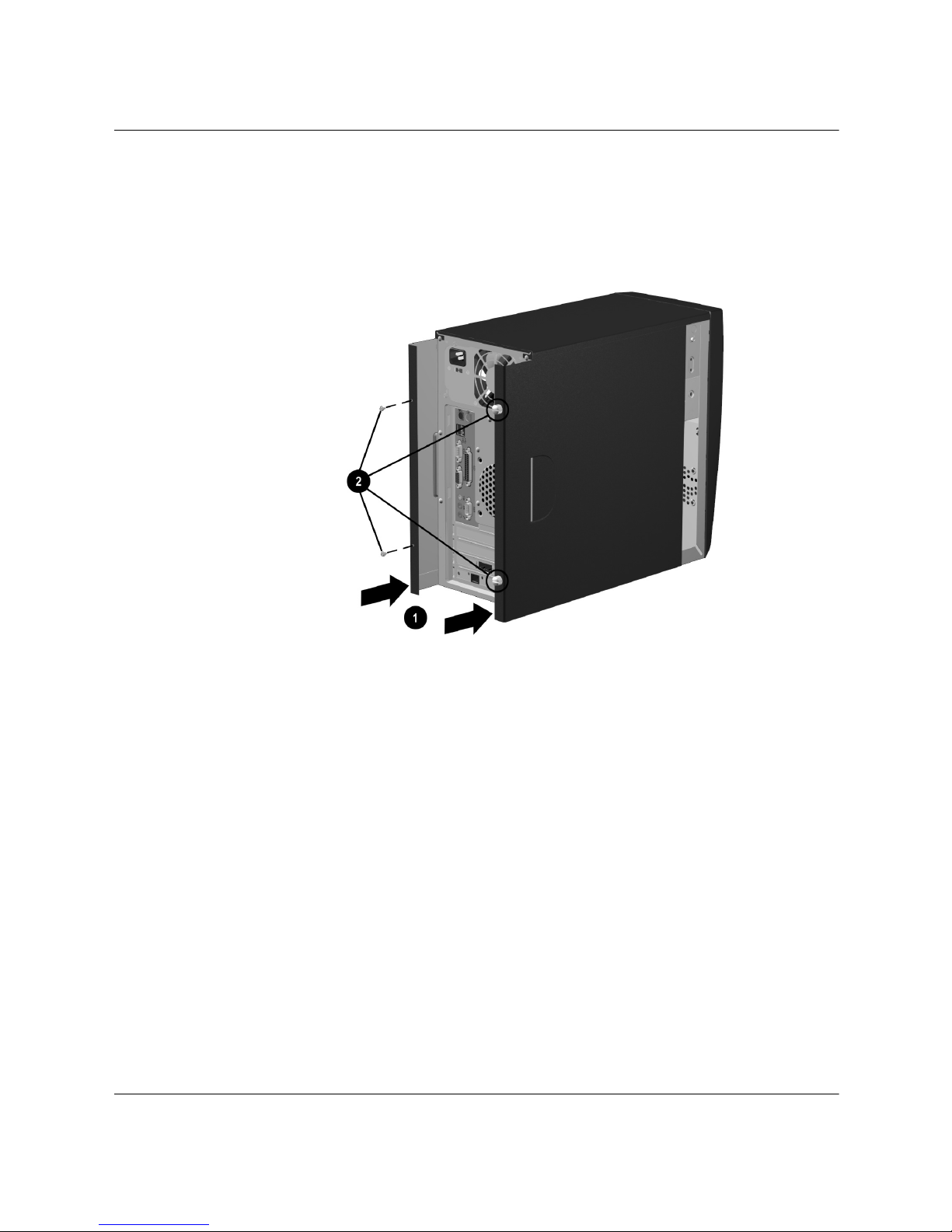
2. Place the side access panels in the proper position on the chassis
and slide them into place 1. Ensure that the holes for the
thumbscrews are aligned with the holes on the chassis and replace
the thumbscrews 2.
Replacing the Side Acess Panels
3–28 Hardware Reference Guide
Page 46
Computer Upgrades
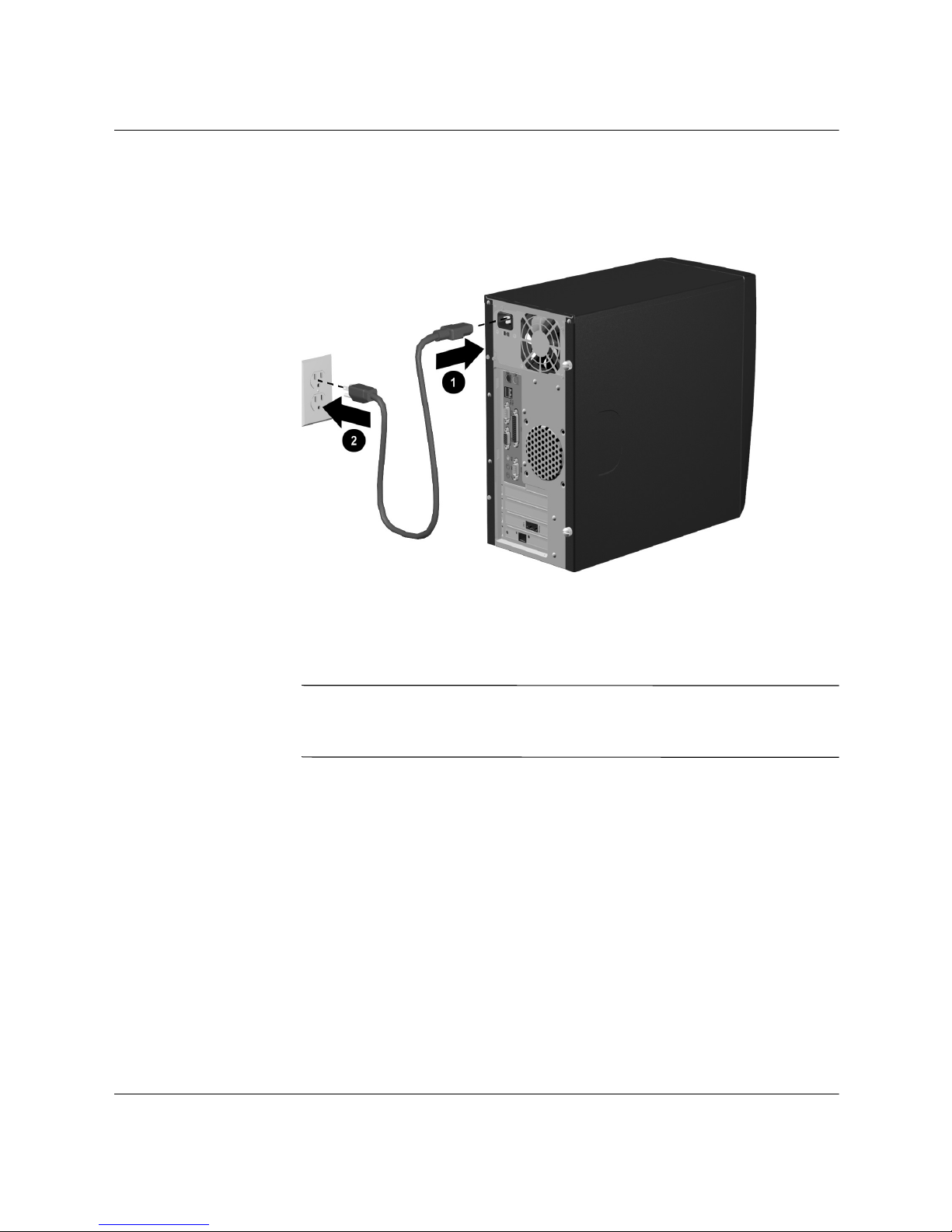
3. Reconnect the power cable 1 to the computer and plug the cable
into an electrical outlet 2.
Å
Reconnecting the Power Cable
4. Reconnect all peripheral devices to the computer.
WARNING: To reduce the risk of electrical shock, fire, or damage to the
equipment, do not plug telecommunications or telephone connectors
into the network interface controller (NIC) ports.
5. Turn on the computer by pressing the power button.
Hardware Reference Guide 3–29
Page 47

Electrostatic Discharge
A discharge of static electricity from a finger or other electrostatic
conductor may damage electronic components. Before handling
electrostatic-sensitive components, discharge static electricity by one
the methods described in this appendix.
Preventing Electrostatic Damage
When Handling Drives
■ Before handling a drive, discharge static electricity by touching
the unpainted metal surface or lug nuts on the connectors on the
rear of the computer.
■ Avoid touching connector pins on the computer or a drive.
A
When Installing Internal Components
■ Keep components in their electrostatic-safe containers until you
are ready to install them.
■ Have everything needed for the installation within reach so that
you do not have to leave the area after beginning installation.
■ Use nonmagnetic tools.
■ Avoid touching pins, leads, and circuitry. Handle electronic
components as little as possible.
■ If you remove a component, place it in an electrostatic-safe
container.
Hardware Reference Guide A–1
Page 48

Specifications
Depending on your computer model, specifications may vary.
Compaq 4000 Series Computer
Desktop Dimensions
Height
Width
Depth
Approximate Weight 20.0 lb 9.1 kg
3.8 in
12.5 in
14.6 in
9.7 cm
31.8 cm
37.1 cm
B
Weight Supported (maximum distributed
load)
Temperature Range
Operating
Nonoperating
Relative Humidity (noncondensing)
Operating
Nonoperating
Maximum Altitude (unpressurized)
Operating
Nonoperating
Power Supply
Operating Voltage Range
Rated Voltage Range
Rated Line Frequency
100.0 lb 45.5 kg
50° to 95°F
-4° to 140°F
8-90%
5-95%
10,000 ft
30,000 ft
90-132 VAC
100-127 VAC
50-60 Hz
-20° to 60°C
180-264 VAC
200-240 VAC
10° to 35°C
8-90%
5-95%
3048 m
9144 m
50-60 Hz
Hardware Reference Guide B–1
Page 49

Specifications
Compaq 4000 Series Computer (Continued)
Power Output 200 W 200 W
Rated Input Current (maximum) 6 A 3 A
Heat Dissipation
Maximum
Nominal
1050 BTU/hr
525 BTU/hr
264 kg-cal/hr
132 kg-cal/hr
B–2 Hardware Reference Guide
Page 50

Index
A
access panels
removing
replacing 3–28
adding drives
adding memory
audio connectors
line-in
line-out
3–3
3–12
3–20
1–4
1–4
B
backup files 3–5, 3–18
C
CD-ROM drive 1–2
installation
CD-RW drive
installation 3–5
components
Easy Access keyboard
front panel
mouse
rear panel 1–3
3–5
1–2
1–2
1–5
D
diskette drive 1–2
activity light
eject button
installation
drive locations
CD drive
diskette drive
DVD drive 3–6
hard drive
drive positions
1–2
1–2
3–5
3–6
3–6
3–6
3–6
2–1
DVD-ROM drive
installation 3–5
1–2
E
Easy Access Buttons 2–2
Easy Access keyboard
customizing buttons
identifying buttons
using 2–2
electrostatic discharge
expansion card
installation
3–23
2–4
2–3
3–1, A–1
F
front bezel
removing 3–4
replacing
front panel components
3–27
1–1
H
hard drive
activity light 1–2
installation
3–5
I
installation
drives
expansion cards
memory
installing upgrades
3–5
3–23
3–19
3–1
K
keyboard
connector
identifying keys
1–3
2–1
Hardware Reference Guide Index–1
Page 51

Index
M
memory
installation
location
mircrophone 1–4
modem connector
mouse
connector
customizing
left button
optical mouse
right button
scroll mouse
scroll wheel
wireless wheel mouse
3–18
3–19
1–4
1–6
1–5
1–7
1–5
1–6
1–5
N
NIC connector 1–4
O
optical drives 1–2
activity light
eject button
optical mouse
1–2
1–2
1–5
P
parallel 1–4
power
button
cord connector 1–3
light
1–2
1–2
1–4
1–6
power cord
connecting
disconneting 3–2
3–29
R
rear components 1–3
removing drives
restoring software
3–6
3–18
S
scroll mouse 1–5
second serial port
serial port
specifications
system status lights
1–3
1–4
B–1
2–6
T
telephone 1–4
U
upgrades 3–1
1–2, 1–3
USB
V
video 1–4
voltage select switch
voltage selections
1–3
1–3
W
Windows Logo key 2–5
wireless mouse 1–5
Index–2 Hardware Reference Guide
 Loading...