

Page 1

HP PDR Management Module User Guide
Part Number 484051-003
October 2009 (Third Edition)
Page 2

© Copyright 2008, 2009 Hewlett-Packard Development Company, L.P.
The information contained herein is subject to change without notice. The only warranties for HP products and services are set forth in the express
warranty statements accompanying such products and services. Nothing herein should be construed as constituting an additional warranty. HP
shall not be liable for technical or editorial errors or omissions contained herein.
Confidential computer software. Valid license from HP required for possession, use or copying. Consistent with FAR 12.211 and 12.212,
Commercial Computer Software, Computer Software Documentation, and Technical Data for Commercial Items are licensed to the U.S.
Government under vendor’s standard commercial license.
Microsoft and Windows are U.S. registered trademarks of Microsoft Corporation.
Intended audience
This document is for the person who installs and maintains power products. HP assumes you are qualified
in the servicing of high-voltage equipment and trained in recognizing hazards in products with hazardous
energy levels.
Page 3

Contents
Overview..................................................................................................................................... 6
Introduction .............................................................................................................................................. 6
Features...................................................................................................................................................6
Web interface requirements........................................................................................................................ 6
Component identification............................................................................................................... 8
Front panel............................................................................................................................................... 8
Mechanical components............................................................................................................................. 8
Installing the HP PDR Management Module.................................................................................... 10
Required tools......................................................................................................................................... 10
Connecting the network cable................................................................................................................... 10
Connecting the configuration cable ........................................................................................................... 10
Launching a terminal emulation program.................................................................................................... 11
Configuring the management module for remote access ...............................................................................12
HP PDR Management Module web interface.................................................................................. 14
Accessing the web interface ..................................................................................................................... 14
Web browser ............................................................................................................................... 14
Signing in to the web interface.................................................................................................................. 14
Browser security alert............................................................................................................................... 15
Establishing a secure session for Internet Explorer .............................................................................. 16
Secure session for Mozilla or SeaMonkey......................................................................................... 16
Establishing a secure session for Firefox ........................................................................................... 17
Navigating the web interface.................................................................................................................... 17
Home tab............................................................................................................................................... 18
Overview menu............................................................................................................................. 18
Alarms menu................................................................................................................................. 22
Identification menu ........................................................................................................................25
Parameters menu........................................................................................................................... 26
Logs tab................................................................................................................................................. 29
Event Log menu............................................................................................................................. 30
Application Log menu .................................................................................................................... 31
Setup tab ...............................................................................................................................................32
My Account menu ......................................................................................................................... 33
User Accounts menu ...................................................................................................................... 34
Network menu ..............................................................................................................................35
Network Management menu........................................................................................................... 36
ModBus menu............................................................................................................................... 42
Help tab................................................................................................................................................. 47
About menu.................................................................................................................................. 47
Contents menu .............................................................................................................................. 48
Info & Updates menu .....................................................................................................................48
HP PDR Management Module Service Menu.................................................................................. 49
HP PDR Management Module Service Menu overview .................................................................................49
Accessing the Service Menu .....................................................................................................................49
Telnet session................................................................................................................................ 49
Page 4

Terminal emulation session ............................................................................................................. 50
POST..................................................................................................................................................... 50
Navigating the menus.............................................................................................................................. 50
Service Menu.......................................................................................................................................... 51
HP PDR Management Module Configuration Utility...................................................................................... 51
PDR Monitor submenu.................................................................................................................... 51
Network Configuration submenu .....................................................................................................52
ModBus Configuration submenu...................................................................................................... 55
System Configuration submenu........................................................................................................ 55
User Accounts submenu.................................................................................................................. 56
Troubleshooting.......................................................................................................................... 57
Browser does not display the web interface for an installed management module............................................ 57
Certificate error....................................................................................................................................... 57
Error LED illuminates or flashes.................................................................................................................. 58
FTP error messages appear when connecting through Linux .......................................................................... 58
Flash update fails over a serial connection.................................................................................................. 58
HP SIM lists a discovered PDR as Unmanaged in the System Type column ......................................................58
LCD configuration matches the panel breaker ratings................................................................................... 58
Non-admin users cannot log in through telnet.............................................................................................. 59
Unable to obtain a valid network address error message displays .................................................................59
Technical support........................................................................................................................ 60
Before you contact HP.............................................................................................................................. 60
HP Power Distribution Rack support and contact information ......................................................................... 60
Regulatory compliance notices ..................................................................................................... 61
Regulatory compliance identification numbers............................................................................................. 61
Federal Communications Commission notice............................................................................................... 61
FCC rating label............................................................................................................................ 61
Class A equipment......................................................................................................................... 61
Class B equipment......................................................................................................................... 61
Declaration of conformity for products marked with the FCC logo, United States only....................................... 62
Modifications.......................................................................................................................................... 62
Canadian notice (Avis Canadien).............................................................................................................. 62
European Union regulatory notice .............................................................................................................63
Disposal of waste equipment by users in private households in the European Union......................................... 63
Japanese notice ...................................................................................................................................... 64
BSMI notice............................................................................................................................................ 64
Systems Insight Manager integration............................................................................................. 65
Systems Insight Manager overview ............................................................................................................ 65
Discovering the management module......................................................................................................... 66
Configuring HP SIM to receive traps .......................................................................................................... 66
Configuring the management module to send traps to HP SIM....................................................................... 67
Security considerations................................................................................................................ 68
Security considerations overview............................................................................................................... 68
Optional PDR monitoring using SNMP .......................................................................................... 69
PDR monitoring ....................................................................................................................................... 69
HP PDR Management Module quick setup ..................................................................................... 70
Quick setup information ........................................................................................................................... 70
Changing from BootP to a static IP............................................................................................................. 70
Accessing the online application with a known IP address ............................................................................ 71
Page 5

Updating the firmware ................................................................................................................ 72
Updating the firmware overview................................................................................................................ 72
Acronyms and abbreviations........................................................................................................ 73
Index......................................................................................................................................... 75
Page 6

Overview
Introduction
The HP PDR Management Module enables you to monitor and manage environments of PDRs through the
serial and network connectors located on the front of the management module. The management module
can be configured to send alert traps to HP Systems Insight Manager and other SNMP management
programs or used as a stand-alone management system.
For configuration and status monitoring, the management module includes:
• HP PDR Management Module web interface (on page 14)—A graphical interface that is accessed
with a web browser
• HP PDR Management Module Service Menu (on page 49)—A text-based menu that is accessed
through telnet or a terminal emulation session
Features
• Monitors the status of the PDR
• Sends customized email and broadcast notification messages and SNMP traps
• Displays logs for analysis
• Includes enhanced HP SIM integration
• Supports serial- and network-attached server communications
• Supports data monitoring of ModBus data through RTU or TCP protocols
Web interface requirements
The following table lists the minimum requirements necessary to operate the web interface.
Software Browser
Web browser on
a client
Microsoft® operating systems
• Microsoft® Internet Explorer 6.0 with Service Pack
1 (32-bit only)
• Microsoft® Internet Explorer 7.0 (32-bit only)
• Firefox 2.0.x
• Mozilla 1.6.x
Red Hat Linux operating system (32-bit only)
• Firefox 2.0.x
• Mozilla 1.6.x
SUSE Linux operating system (32-bit only)
• Firefox 2.0.x
• Mozilla 1.6.x
Overview 6
Page 7

Software Browser
HP-UX operating system (32-bit only)
• Mozilla 1.6.x
Monitor
resolution
Minimum supported resolution of 1024 x 768, 16-bit
high color (maximize browser window for optimal
display)
Overview 7
Page 8
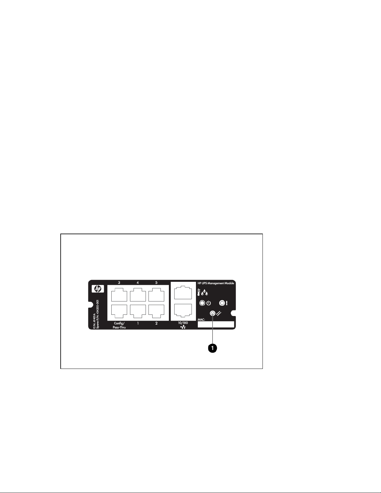
Component identification
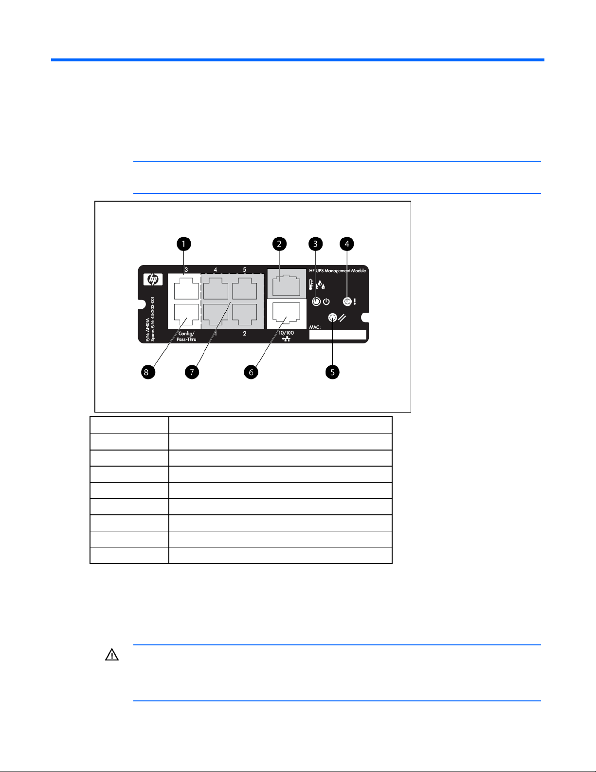
Front panel
NOTE: This module is used for both the PDR and the UPS. For use in the PDR, see the HP
Item Description
1 ModBus RTU
2 RJ-11 port (not for PDR use)
3 Power LED
4 Error LED
5 Reset button
6 Network connector
7 Not for PDR use
8 Config/Pass-Thru connector
website (http://www.hp.com/go/rackandpower) for the latest firmware.
Mechanical components
You must remove the mechanical components installed on the PDR to enable full access to the internal and
operational components inside the rack.
WARNING: The installation of options, routine maintenance, and service of the PDR must be
performed by individuals who are knowledgeable about the procedures, precautions, and
hazards associated with AC power products. There are no user serviceable components
inside the unit.
Component identification 8
Page 9
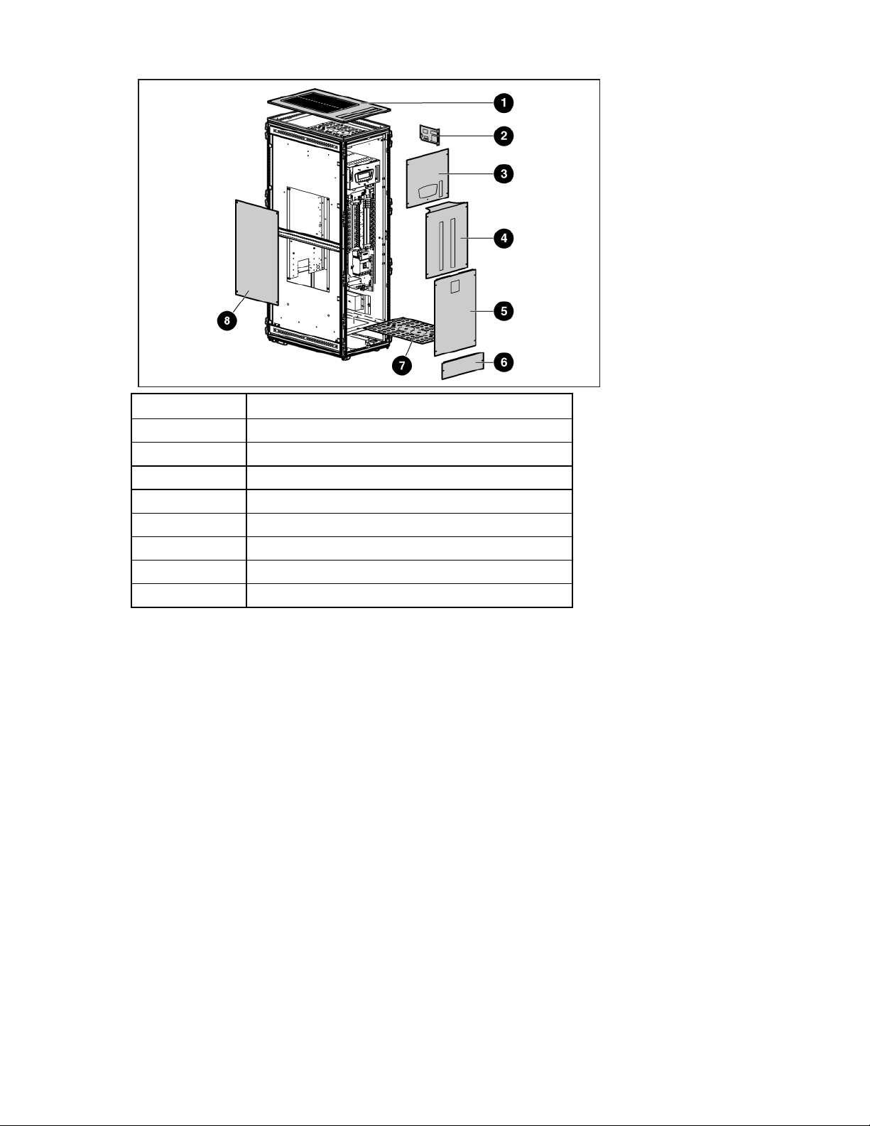
Callout Description
1 Rack access panel
2 Management module card
3 LCD display panel (2)
4 Circuit breaker panel (2)
5 Base panel (2)
6 Floor panel (2)
7 Knockout panel (2)
8 Side access panel
Component identification 9
Page 10
Installing the HP PDR Management Module
Required tools
No. 2 Phillips screwdriver
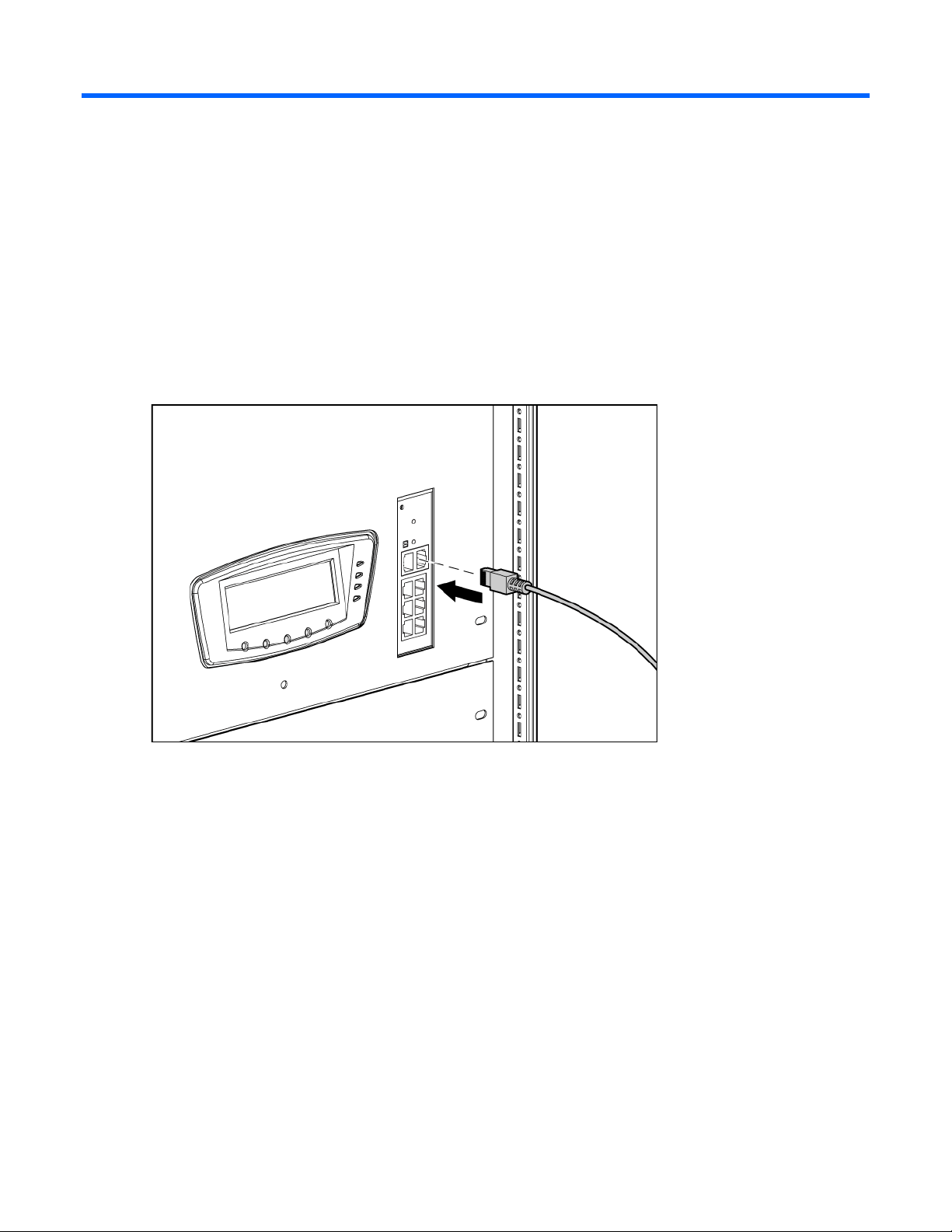
Connecting the network cable
Connect a standard Ethernet cable between the network connector on the management module and a
network jack.
This connection is used to access the management module remotely through telnet or the web interface.
The management module also uses the network connection to facilitate ModBus and SNMP-based
monitoring.
Connecting the configuration cable
1. Connect a DB-9 to RJ-45 adapter to a serial connector on the host computer.
Installing the HP PDR Management Module 10
Page 11
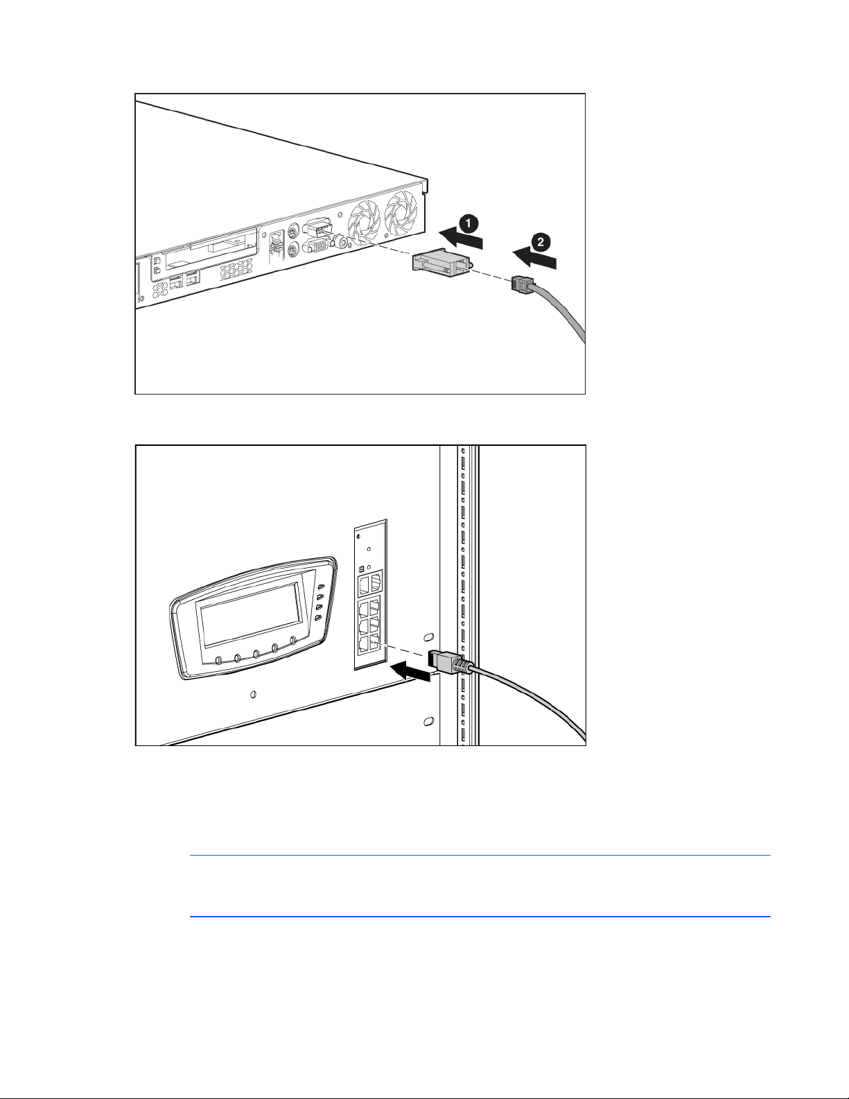
2.
Connect one end of an RJ-45 cable to the RJ-45 connector on the adapter.
3. Connect the other end of the RJ-45 cable to the Config/Pass-Thru connector on the management
module.
This connection is used to configure and access the management module locally through a terminal
emulation program.
Launching a terminal emulation program
NOTE: HyperTerminal is the serial communication program provided with Microsoft®
Windows® and is used in this section as an example for setting up a terminal emulation
1. On the host computer, click Start, and select
session. If you are using another utility, the steps might be different.
Programs>Accessories>Communications>HyperTerminal.
The Connection Description window appears.
Installing the HP PDR Management Module 11
Page 12
2.
Enter a description, select an icon for the connection, and then click OK. The Connect To window
appears.
3. Select the serial connector on the host computer to which the DB-9 to RJ-45 adapter is attached, and
then click OK. The COM Properties window appears.
4. Select the following parameter values, and then click OK.
o Bits per second—115200
o Data bits—8
o Parity—None
o Stop bits—1
o Flow control—None
Configuring the management module for remote access
1. Be sure that you have connected the network cable ("Connecting the network cable" on page 10) to
the management module.
2. Be sure that you have connected the configuration cable ("Connecting the configuration cable" on
page 10) to the management module and the host computer with an open terminal emulation
session.
3. Press the Reset button on the management module front panel.
On the terminal emulation session screen running on the host computer, the POST executes, and the
following prompt appears:
Press any key in 5 seconds to enter Service menu.
4. Press a key to enter the HP PDR Management Module Service Menu.
Use the HP PDR Management Module Service Menu to configure the minimum settings required to
access the management module remotely using telnet or the web interface. You can configure other
settings using this utility in conjunction with a terminal emulation program or a telnet connection.
Installing the HP PDR Management Module 12
Page 13

NOTE: If your network is configured with a BOOTP server, the network settings are
automatically assigned. Verify and note the assigned values.
5. If your network is not configured with a BOOTP server:
a. On the Main menu, enter 1 at the prompt to open Module Configuration submenu.
b. Enter 2 at the prompt to enter the Network Configuration submenu.
c. Enter 1 at the prompt to enter the Network Settings submenu.
6. From this menu, change the mode used to acquire a network IP address to Static IP. You can also
change the IP address, subnet mask, and default gateway of the HP PDR Management Module.
7. Configure web access:
a. On the Network Configuration submenu, enter 3 at the prompt to open the Web Access
submenu.
b. Use the submenu options to select HTTP (default) or HTTPS and configure the associated port. The
default port for HTTP is port 80, and the default port for HTTPS is port 443.
8. Configure telnet access:
a. On the Network Configuration submenu, enter 2 at the prompt to open the Remote Console
submenu.
b. Use the submenu options to configure the telnet port. The default port is port 23.
9. Enter 0 at the prompt until you have returned to the Main menu.
10. Enter s at the prompt to save the changes and restart the management module.
Installing the HP PDR Management Module 13
Page 14

HP PDR Management Module web interface
Accessing the web interface
You can access the web interface remotely through a Web browser (on page 14).
Web browser
Use a web browser to access the HP PDR Management Module web interface:
1. If necessary, configure the management module by:
a. Launching a terminal emulation program (on page 11).
b. Configuring the management module for remote access (on page 12).
2. Be sure that you have connected the network cable ("Connecting the network cable" on page 10) to
the management module.
3. Press the Reset button on the management module front panel. The management module discovers
attached PDRs.
4. Launch a supported browser. The browser window appears.
5. In the Address field (Microsoft Internet Explorer) or the Location field (Mozilla, Firefox, and
SeaMonkey), enter one of the following:
http://xxx.xxx.xxx.xxx
https://xxx.xxx.xxx.xxx
where xxx.xxx.xxx.xxx is the IP address of the management module. The log in screen appears.
6. Sign in through the web browser ("Signing in to the web interface" on page 14).
NOTE: For a complete list of the browser requirements, see "Web interface requirements."
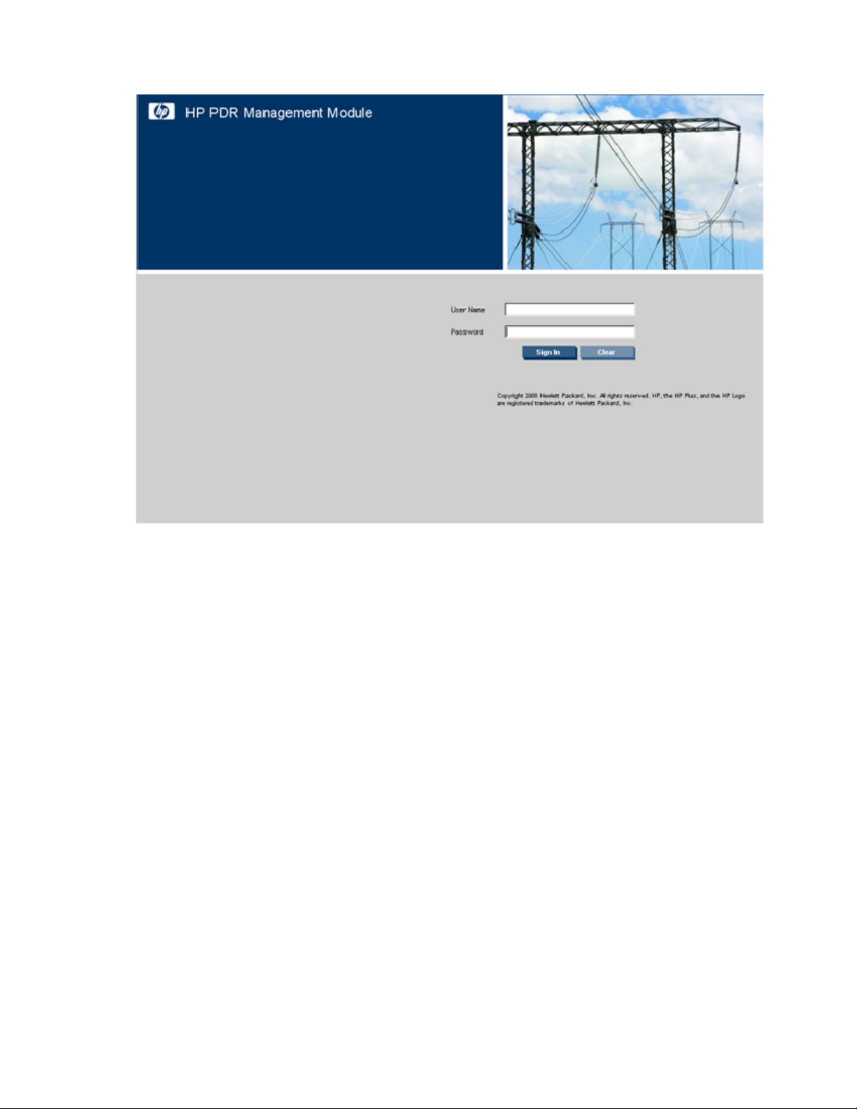
Signing in to the web interface
1. Enter the user name in the User Name field. The default user name is admin.
2. Enter the password in the Password field. The default password is admin.
NOTE: Passwords are case-sensitive.
3. Click Sign In. The HP PDR Management Module web interface appears.
-orClick Clear to clear the credentials.
For information regarding the interface, see "Navigating the web interface (on page 17)."
HP PDR Management Module web interface 14
Page 15
For instructions on changing the password, see "My Account menu (on page 33)."
Admin session logins, logouts, and terminations are recorded in the Event Log menu (on page 30). The
console session timeout length can be modified in the Remote Access tab (on page 41).
The following is a list of recommended password guidelines.
• Passwords should not be shared with others.
• Passwords should be limited to one or two people, if shared with others.
• Passwords should be coordinated to prevent inadvertent logouts, should more than one person know
them.
• Passwords are case-sensitive.
• Passwords can be between 1 and 15 alphanumeric characters in length.
Browser security alert
Secure browsing requires the use of SSL. SSL is a protocol layer that lies between HTTP and TCP that
provides secure communication between a server and a client and is designed to provide privacy and
message integrity. SSL is commonly used in web-based transactions to authenticate the web server, which
indisputably identifies the server to the browser. SSL also provides an encrypted channel of
communication between the server and the browser. The encrypted channel ensures integrity of the data
between the web server and the browser, so that data can neither be viewed nor modified while in
transit. The management module uses a system generated and unique key.
An integral part of SSL is a security certificate, which identifies the management module. If your browser
displays a security alert when browsing to the management module, it can be for one of several reasons:
HP PDR Management Module web interface 15
Page 16

• The certificate is untrusted, meaning it was signed by a certifying authority that is unknown to your
browser.
• The certificate has expired or is not yet valid. This condition can occur if you issue your own
certificate and it has expired.
• The name on the certificate does not match the name of the site in the browser address field.
For more information about security considerations, see "Security considerations overview (on page 68)."
Establishing a secure session for Internet Explorer
The first time you browse to the management module, the Secure Session screen appears. To ensure a
secure connection, verify that you are browsing to the desired management module:
1. Click View Certificate.
2. Verify that the name in the Issued To field is the name of your management module.
3. Perform any other steps necessary to verify the identity of the management module.
CAUTION: If you are not sure this is the desired management module, do not proceed.
Importing a certificate from an unauthorized source relays your login credentials to that
After verifying the management module, do one of the following:
• Import the certificate and proceed.
unauthorized source. Exit the certificate window and contact the system administrator.
a. Click View Certificate. The certificate appears.
b. Click Install Certificate. The Certificate Import wizard runs.
c. Click Next. The Certificate Store screen appears.
d. Select Automatically select the certificate store based on the type of certificate, and click Next.
e. Click Finish. A message appears, asking for verification of the root store.
f. Click Yes.
• Proceed without importing the certificate by clicking Yes at the Security Alert window. You continue
to receive the Security Alert each time you log in until you import the certificate. Your data is still
encrypted.
• Exit and import the certificate into your browser from a file provided by the administrator.
a. Click No at the Security Alert window.
b. Obtain an exported certificate file from the administrator.
NOTE: If using Internet Explorer, you can manually import the file into the browser by clicking
Tools>Internet Options>Content>Certificates>Import.
Secure session for Mozilla or SeaMonkey
The first time you browse to the management module, the Secure Session screen appears. To ensure a
secure connection, verify that you are browsing to the desired management module:
1. Click Examine Certificate.
2. Verify that the name in the Issued To field is the name or IP address of your management module.
HP PDR Management Module web interface 16
Page 17

3.
Perform any other steps necessary to verify the identity of the management module.
4. After verifying the management module, do one of the following:
a. Click either Accept this certificate permanently or Accept this certificate temporarily for this
session.
b. Click OK.
NOTE: If using Mozilla or SeaMonkey, you can manually import the file into the browser by
clicking Edit>Preferences>Privacy & Security>Certificates>Manage
Certificates>Authorities>Import.
Establishing a secure session for Firefox
The first time you browse to the management module, the Secure Session screen appears. To ensure a
secure connection, verify that you are browsing to the desired management module:
1. Click Examine Certificate.
2. Verify that the name in the Issued To field is the name or IP address of your management module.
3. Perform any other steps necessary to verify the identity of the management module.
4. After verifying the management module, do one of the following:
a. Click either Accept this certificate permanently or Accept this certificate temporarily for this
session.
b. Click OK.
NOTE: If using Firefox, you can manually import the file into the browser by clicking
Edit>Preferences>Advanced>Security>View Certificates>Authorities>Import.
Navigating the web interface
The web interface is divided into three frames:
• Top frame—Contains a Sign Out hyperlink, Home tab, Logs tab, Setup tab, and Help tab
o Click the Sign Out hyperlink to log out of the interface.
o Click the Home tab to see the menu options for viewing general status information. For more
information, see "Home tab (on page 18)."
o Click the Logs tab to see the menu options for displaying data logs. For more information, see
"Logs tab (on page 29)."
o Click the Setup tab to see the menu options for configuring the management module and setting
up and modifying user accounts. For more information, see "Setup tab (on page 32)."
o Click the Help tab to access the interface information and help section. For more information, see
"Help tab (on page 47)."
• Left navigation frame—Contains a list of menu options, a list of alarms and warnings, and a legend
o The options menu is dynamic, and the options listed change depending on the tab selected and
your access rights.
o The list of alarms and warnings displays the individual alarm status for the managed PDR. The
graphical indicator displays the number of active alarms and displays the icon for the most
severe alarm. The date and time of the last update is also indicated.
HP PDR Management Module web interface 17
Page 18

o
The legend displays the meaning of symbols used in the interface. Expand and collapse the
legend by clicking the arrow in the upper right corner.
• Main frame—Contains the various interface screens based on the menu option selected in the left
navigation frame
Home tab
Menu options listed under the Home tab include:
• Overview menu (on page 18)
• Alarms menu (on page 22)
• Identification menu (on page 25)
• Parameters menu (on page 26)
Overview menu
Click Overview in the left navigation frame to display the Overview screen. This screen displays graphical
information, where colors represent the current state of the PDR.
Color Status
Green Normal
Yellow Warning
Red Critical
NOTE: The current rating is 400 A for the North American model.
The PDR Output tab graphically displays overall status information for your model.
HP PDR Management Module web interface 18
Page 19
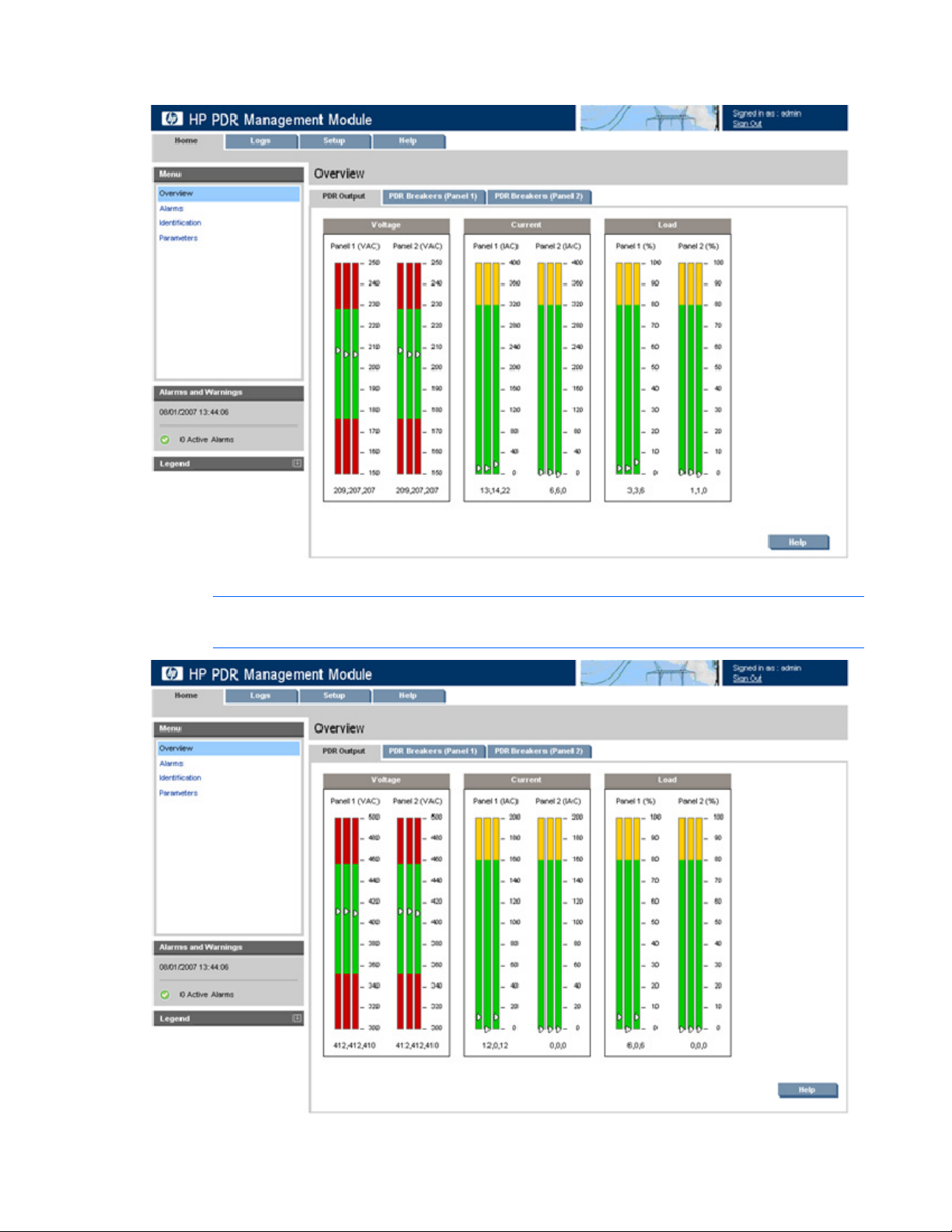
The following screen shows an example of the overall PDR status for the North American model.
The following screen shows an example of the overall PDR status for the International model
NOTE: The current rating is 200 A for the International model.
HP PDR Management Module web interface 19
Page 20
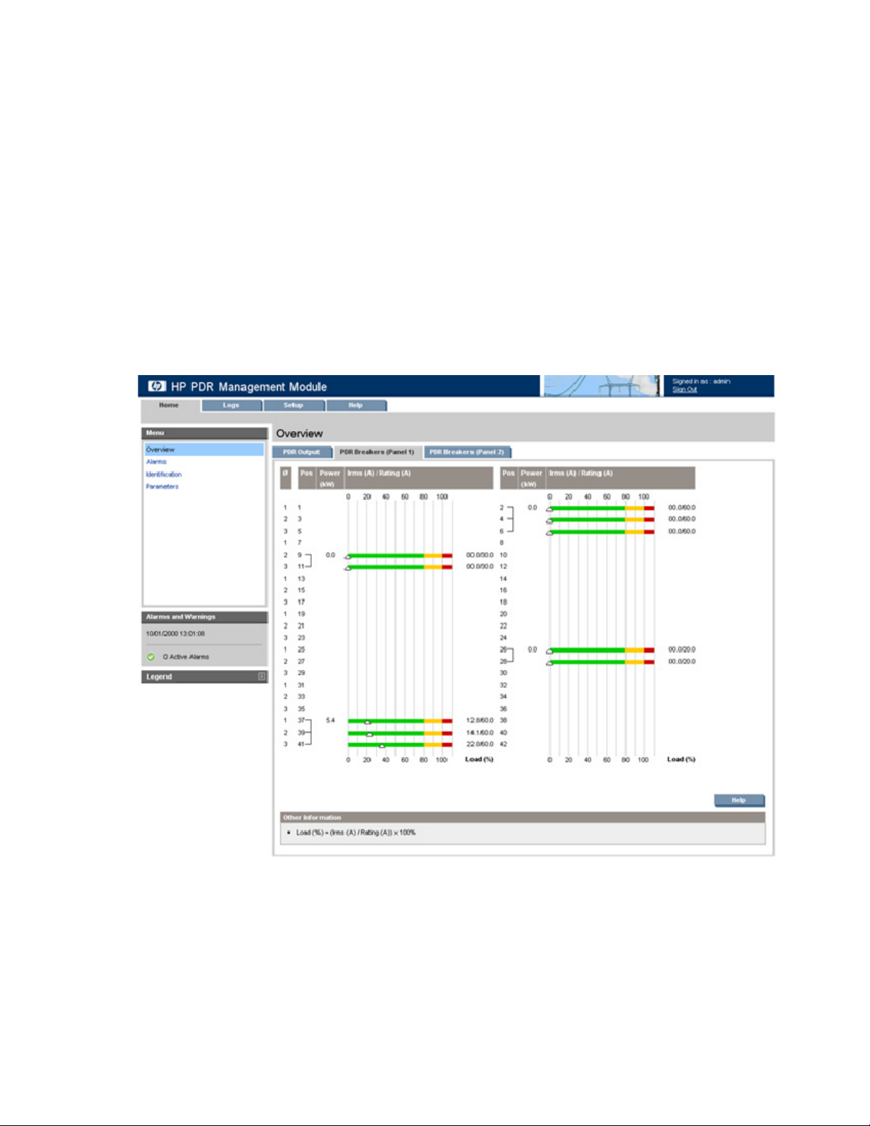
Click Help to view online help.
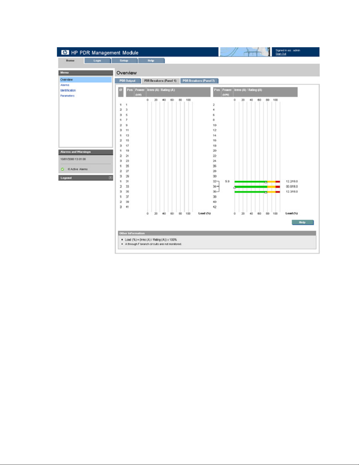
Click the PDR Breakers (Panel 1) or PDR Breakers (Panel 2) tab to display the current power and the load
percent for each position.
The following information is displayed for each breaker:
• Phase—The phase position of the breaker
• Position—The position to where the breaker is connected to on Panel 1
• Power (KW)—The current power of the breaker
• Irms (A)—Root-Mean-Square current across through the breaker
• Rating (A)—The current rating of the breaker
• Load (%)—Irms (A) / Rating (A) x 100%
The following screen shows an example of the information available for the PDR Breakers (Panel 1) North American model.
HP PDR Management Module web interface 20
Page 21
The following screen shows an example of the information available for the PDR Breakers (Panel 1) International model.
HP PDR Management Module web interface 21
Page 22
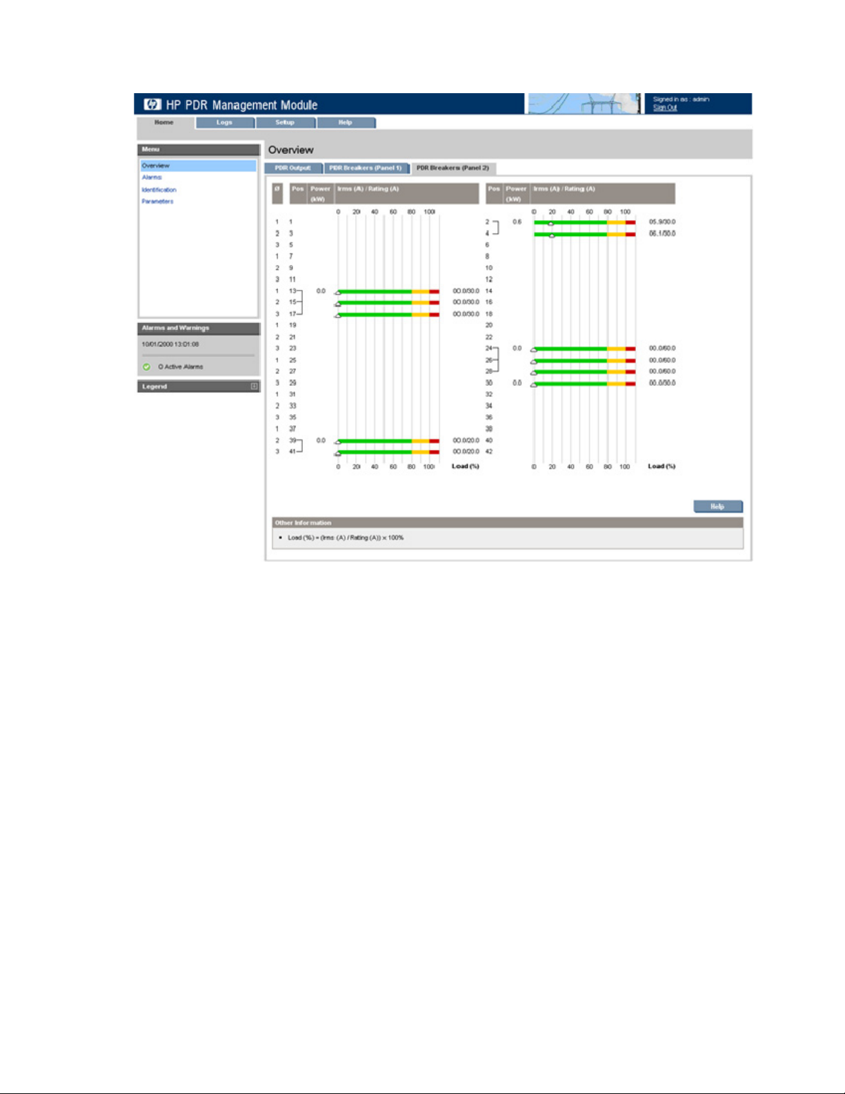
The following screen shows an example of the information available for the PDR Breakers (Panel 2).
Click Help to view online help.
Alarms menu
Click Alarms in the left navigation frame to display the Alarms screen. This screen displays the alarms for
the PDR. The alarms are listed in alphabetical order. Each entry includes a description and the date and
time at which the alarm most recently occurred.
HP PDR Management Module web interface 22
Page 23
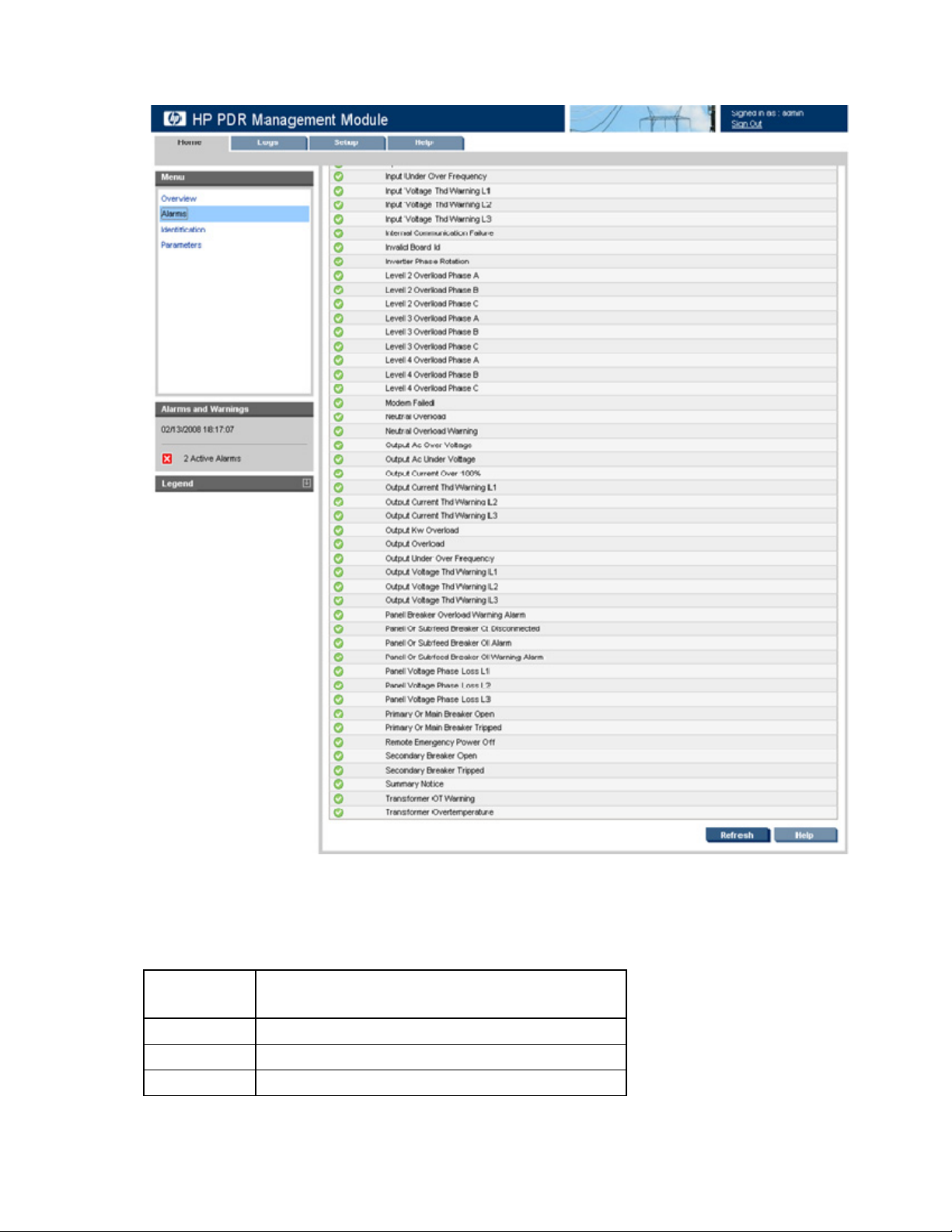
For a complete list of PDR alarms, see "PDR alarms (on page 23)."
Click Refresh to refresh the screen, or click Help to view online help.
PDR alarms
PDR alarms include:
Alarm
number
6 INPUT_AC_OVER_VOLTAGE
7 INPUT_AC_UNDER_VOLTAGE
8 INPUT_UNDER_OVER_FREQUENCY
Alarm name
HP PDR Management Module web interface 23
Page 24

Alarm
Alarm name
number
9 OUTPUT_AC_OVER_VOLTAGE
10 OUTPUT_AC_UNDER_VOLTAGE
11 OUTPUT_UNDER_OVER_FREQUENCY
12 REMOTE_EMERGENCY_POWER_OFF
16 BUILDING_ALARM_4
17 BUILDING_ALARM_3
18 BUILDING_ALARM_2
19 BUILDING_ALARM_1
25 OUTPUT_OVERLOAD
50 OUTPUT_CURRENT_OVER_100PERCENT
53 EEPROM_FAULT
63 INTERNAL_COMMUNICATION_FAILURE
90 INPUT_PHASE_ROTATION_ERROR
97 EMERGENCY_SHUTDOWN_COMMAND
159 LEVEL_2_OVERLOAD_PHASE_A
160 LEVEL_2_OVERLOAD_PHASE_B
161 LEVEL_2_OVERLOAD_PHASE_C
162 LEVEL_3_OVERLOAD_PHASE_A
163 LEVEL_3_OVERLOAD_PHASE_B
164 LEVEL_3_OVERLOAD_PHASE_C
165 LEVEL_4_OVERLOAD_PHASE_A
166 LEVEL_4_OVERLOAD_PHASE_B
167 LEVEL_4_OVERLOAD_PHASE_C
201 TRANSFORMER_OVERTEMPERATURE
211 MODEM_FAILED
224 CONFIGURATION_ERROR
228 SUMMARY_NOTICE
229 SUMMARY_ALARM
238 INVERTER_PHASE_ROTATION
241 INVALID_BOARD_ID
243 OUTPUT_KW_OVERLOAD
264 XFRMR_OT_WARNING
266 HIGH_INPUT_THD_L1
267 HIGH_INPUT_THD_L2
268 HIGH_INPUT_THD_L3
269 HIGH_OUTPUT_THD_L1
270 HIGH_OUTPUT_THD_L2
271 HIGH_OUTPUT_THD_L3
HP PDR Management Module web interface 24
Page 25

Alarm
Alarm name
number
272 NEUTRAL_OVERLOAD_WARNING
273 NEUTRAL_OVERLOAD
274 GROUND_CURRENT_WARNING
275 GROUND_CURRENT_OVERLOAD
276 INPUT_VOLTAGE_THD_WARNING_L1
277 INPUT_VOLTAGE_THD_WARNING_L2
278 INPUT_VOLTAGE_THD_WARNING_L3
279 INPUT_CURRENT_THD_WARNING_L1
280 INPUT_CURRENT_THD_WARNING_L2
281 INPUT_CURRENT_THD_WARNING_L3
282 OUTPUT_VOLTAGE_THD_WARNING_L1
283 OUTPUT_VOLTAGE_THD_WARNING_L2
284 OUTPUT_VOLTAGE_THD_WARNING_L3
285 OUTPUT_CURRENT_THD_WARNING_L1
286 OUTPUT_CURRENT_THD_WARNING_L2
287 OUTPUT_CURRENT_THD_WARNING_L3
288 PANEL_VOLTAGE_PHASE_LOSS_L1
289 PANEL_VOLTAGE_PHASE_LOSS_L2
290 PANEL_VOLTAGE_PHASE_LOSS_L3
299 PANEL_OR_SUBFEED_BREAKER_OL_WARNING_ALARM
300 PANEL_OR_SUBFEED_BREAKER_OL_ALARM
301 PANEL_OR_SUBFEED_BREAKER_CT_DISCONNECTED
302 PANEL_BREAKER_OVERLOAD_WARNING_ALARM
303 PANEL_BREAKER_OVERLOAD_ALARM
304 PRIMARY_OR_MAIN_BREAKER_OPEN
305 PRIMARY_OR_MAIN_BREAKER_TRIPPED
306 SECONDARY_BREAKER_OPEN
307 SECONDARY_BREAKER_TRIPPED
Identification menu
Click Identification in the left navigation frame to display the Identification screen.
HP PDR Management Module web interface 25
Page 26

Click the Management Module tab to display contact information and specific device information about
the management module.
Click the PDR tab to display specific device information about the PDR.
Enter the system name and contact information using the System Information tab (on page 37) on the
Network Management screen.
Click Refresh to refresh the screen, or click Help to view online help.
Parameters menu
Click Parameters in the left navigation frame to display the Parameters screen. A status icon next to each
parameter indicates the current state of the parameter (
Normal, Warning, or Critical).
HP PDR Management Module web interface 26
Page 27

Click the PDR Input & Output tab to display the input and output current and voltage per phase.
Click the PDR Thresholds tab to display the Panel 1 and 2 percentage of load in warning and critical
status. This tab also displays the breaker (Panel 1 and 2) positions, phase, percentage of load in warning
and critical status.
HP PDR Management Module web interface 27
Page 28

This screen shows an example of the information available for the North American model.
HP PDR Management Module web interface 28
Page 29

This screen shows an example of the information available for the International model.
Click Refresh to refresh the screen, or click Help to view online help.
Logs tab
Menu options listed under the Logs tab include:
• Event Log menu (on page 30)
• Application Log menu (on page 31)
HP PDR Management Module web interface 29
Page 30

Event Log menu
Click Event Log in the left navigation frame to display the Event Log screen. This screen displays a log of
the events that have occurred on the PDR.
The following information is displayed for each event:
• Severity—An icon indicating the severity or status of the alarm ( Critical, Minor,
Informational, Normal, or Unknown)
• Description—The name of the event
• Date—The date at which the event occurred
• Time—The time at which the event occurred
HP PDR Management Module web interface 30
Page 31

NOTE: When the log reaches the maximum of 500 entries, new entries overwrite the oldest
entries in the log.
On the Event Log screen:
• Click Download Event Log to export the event log. The File Download screen appears.
o Click Open to view the log in a user-selected application.
o Click Save to save the log file (.csv) to your computer.
• Click Clear Event Log to clear the log files.
• Click Help to view online help.
Application Log menu
Click Application Log in the left navigation frame to display the Application Log screen. This screen
displays a log of all application events that have occurred, such as a user logging in.
HP PDR Management Module web interface 31
Page 32

The following information is displayed for each application event:
• User—The login name of the user who performed the action
• Event—A description of the application event
• Date—The date at which the event occurred
• Time—The time at which the event occurred
NOTE: When the log reaches the maximum of 500 entries, new entries overwrite the oldest
entries in the log.
On the Application Log screen:
• Click Download Application Log to export the application log. The File Download screen appears.
o Click Open to view the log in a user-selected application.
o Click Save to save the log file (.csv) to your computer.
• Click Clear Application Log to clear the log files.
• Click Help to view online help.
Setup tab
Menu options listed under the Setup tab include:
• My Account menu (on page 33)
• User Accounts menu (on page 34)
• Network menu (on page 35)
• Network Management menu (on page 36)
• ModBus menu (on page 42)
HP PDR Management Module web interface 32
Page 33

My Account menu
Click My Account in the left navigation frame to display the My Account screen. This screen enables you
to change your login password.
To change your password:
1. Enter the new password in the Password field.
2. Enter the new password again in the Verify Password field.
3. Do one of the following:
o Click Save Settings to save the new password.
o Click Undo Changes to undo the changes.
o Click Help to view online help.
HP PDR Management Module web interface 33
Page 34

User Accounts menu
Click User Accounts in the left navigation frame to access the User Accounts screen. This screen enables
administrators to manage user accounts.
On the User Accounts screen:
• Click Undo Changes to undo the changes.
• Click Help to view online help.
To add a user account:
1. Enter the user's sign-in name in the Sign In Name field.
2. Enter the user's password in the Password field.
3. Enter the user's password again in the Verify Password field.
4. If the new user is authorized to change the management module settings, select the Administrator
checkbox.
5. Click Save Settings to save the account information.
To modify a user name:
1. Enter the changed name in the Sign In Name field.
2. Enter the user's password in the Password field.
3. Enter the password again in the Verify Password field.
4. If the user has administrator rights added or removed, select or deselect the Administrator checkbox.
5. Click Save Settings to save the updated account information.
To modify a user password:
1. Enter the user's login name in the Sign In Name field.
2. Change the password:
a. Enter the new password in the Password field.
b. Enter the new password again in the Verify Password field.
3. If the user has administrator rights added or removed, select or deselect the Administrator checkbox.
4. Click Save Settings to save the updated account information.
HP PDR Management Module web interface 34
Page 35

To delete a user account:
1. Select the Delete checkbox for the user account that is to be removed.
2. Click Delete Users to delete the user account. The account is removed and no longer appears on the
User Accounts screen.
Network menu
Click Network in the left navigation frame to access the Network screen. This screen enables
administrators to configure network settings for the management module.
The management module MAC address is displayed on the Network screen for informational purposes.
To configure the network settings:
1. Select a radio button to enable or disable BOOTP. By default, BOOTP is enabled.
2. Enter the IP address of the management module.
3. Enter the network mask of the management module.
4. Enter the default gateway of the management module.
5. In the Network Time Protocol (NTP) field, select Enable to enable NTP, or select Disable to set the
date and time manually.
6. If you enabled NTP in step 5:
a. Enter the IP address of the primary NTP server.
b. Enter the IP address of the secondary NTP server.
c. Select the time zone from the dropdown box.
HP PDR Management Module web interface 35
Page 36

d.
Enter the number of hours that should pass between each date and time update.
7. If you disabled NTP in step 5:
a. Enter the date.
b. Enter the time.
c. Select the date format from the dropdown box.
8. Select the Disable radio button if daylight saving time should not be reflected in the time on the
management module.
-orSelect the Enable radio button to configure time adjustment for daylight saving time:
a. Enter the month, day, week, and time for which daylight saving time should start.
b. Enter the month, day, week, and time for which daylight saving time should end.
c. Select the amount of time the clock should change for daylight saving time in your region.
Available options are 30 minutes and 1 hour.
9. Do one of the following:
o Click Save Settings to save the information.
o Click Undo Changes to undo the changes.
o Click Help to view online help.
10. Click Download Configuration File to save a configuration file you can use to duplicate the settings
for this management module on other management modules in your environment.
NOTE: Before saving the configuration file, configure all the settings available on the web
interface exactly as the duplicated modules should be configured.
Click Save on the File Download screen.
Network Management menu
Click Network Management in the left navigation frame to access the Network Management screen. This
screen enables administrators to configure network management settings for the management module.
The Network Management screen contains the following:
• System Information tab (on page 37)
• Trap Receivers tab (on page 38)
• SNMP Managers tab (on page 38)
• Email Setup tab (on page 39)
• Event Notifications tab (on page 40)
• Remote Access tab (on page 41)
HP PDR Management Module web interface 36
Page 37

System Information tab
This screen enables administrators to enter contact information for the management module. The
information entered on this screen appears on the Identification screen ("Identification menu" on page
25).
To configure system information:
1. Enter the name of the management module in the System Name field. This name appears throughout
the interface application and is used in SNMP traps. Use a unique name for each management
module.
2. Enter the name of the contact person in the Contact Name field.
3. Enter the email address of the contact person in the Contact Email field.
4. Enter the phone number of the contact person in the Contact Phone field.
5. Do one of the following:
o Click Save Settings to save the information.
o Click Undo Changes to undo the changes.
o Click Help to view online help.
HP PDR Management Module web interface 37
Page 38

Trap Receivers tab
This screen enables administrators to enter information for servers that should receive SNMP traps from
the management module.
To configure which servers should receive traps:
1. Enable SNMP traps for up to 10 servers.
2. Enter the IP address for up to 10 trap recipients in the IP Address field.
3. Enter the community string for each trap recipient.
4. Do one of the following:
o Click Save Settings to save the information.
o Click Undo Changes to undo the changes.
o Click Help to view online help.
5. Click Send Test Trap to send a test SNMP trap.
SNMP Managers tab
This screen enables administrators to enter information for SNMP managers. SNMP managers are
computers that use the HP Power MIB to request information from the management module.
To configure SNMP managers:
1. Enable the SNMP manager configuration for up to five servers.
HP PDR Management Module web interface 38
Page 39

2.
Enter the IP address for each SNMP manager in the IP Address field.
NOTE: SNMP managers cannot communicate with the management module until the IP
address is entered on the SNMP Managers screen.
3. Enter the Read community string for each SNMP manager.
4. Enter the Write community string for each SNMP manager.
5. Configure the access type for each SNMP manager.
o RO—Read Only
o RW—Read/Write
6. Do one of the following:
o Click Save Settings to save the information.
o Click Undo Changes to undo the changes.
o Click Help to view online help.
Email Setup tab
This screen enables administrators to configure email event notifications.
To configure the email notifications:
1. Enter the mail server IP address in the Email Server Address field.
2. Enter the email address that messages are marked as being sent from in the From Address field.
3. Select the Enable Account checkbox and enter up to 10 email addresses in the Email Address field.
The addresses should correspond to the persons who should receive email notifications of events that
occur.
4. Do one of the following:
o Click Save Settings to save the information.
o Click Undo Changes to undo the changes.
o Click Help to view online help.
HP PDR Management Module web interface 39
Page 40

5.
Click Send Test Email to send a test email.
Event Notifications tab
This screen enables administrators to define the event notifications, emails, or SNMP traps the
management module sends for each event.
To configure the event notifications:
1. For each event description listed, select the Enabled checkbox to indicate that email notifications or
SNMP traps are sent for that event. To enable all events, click the Email checkbox and the SNMP
Trap checkbox at the top of each column.
2. For each email and SNMP trap enabled, enter the number of minutes that should pass between the
occurrence of an alert condition and the sending of the notification.
NOTE: If the event clears before the delay time has expired, then the event notification is not
sent.
3. Do one of the following:
o Click Save Settings to save the information.
o Click Undo Changes to undo the changes.
o Click Help to view online help.
HP PDR Management Module web interface 40
Page 41

Remote Access tab
This screen enables administrators to enter information for remote access to the management module.
To configure remote access:
1. Configure web access by doing one of the following:
o Select Disable to disable web access.
o Select Enable for HTTP Port and enter the port number to use HTTP.
o Select Enable for HTTPS Port and enter the port number to use HTTPS.
o Upload the SSL certificate:
i. Open the SSL certificate file with a text editor.
ii. Select all content.
iii. Copy the selected content.
iv. Paste the copied text to the SSL Key field.
NOTE: If you enable HTTPS, the management module also uses the HTTP port to pass non-
sensitive information. Be sure that both ports are open.
2. Configure telnet access by doing one of the following:
o Select Disable to disable telnet access.
o Select Enable for Telnet Port and enter the port number to use telnet.
3. Configure the session management settings.
a. (optional) Enable automatic signout and enter the number of minutes the management module
should wait before terminating an inactive session.
b. (optional) Enable retries allowed, enter the number of times a user can unsuccessfully log in to
the management module before the account is locked, and enter the number of minutes to wait
between an unsuccessful login and a new login attempt.
4. Enable FTP file upload to allow firmware and configuration upgrades.
HP PDR Management Module web interface 41
Page 42

5.
Do one of the following:
o Click Save Settings to save the information.
o Click Undo Changes to undo the changes.
o Click Help to view online help.
ModBus menu
Click ModBus in the left navigation frame to access the ModBus screen. This screen enables address
selection for the ModBus RTU or TCP and the PDR.
To configure ModBus:
• Configure RTU (serial port communication)
a. Select the ModBus/RTU checkbox.
b. Enter the device address. If you have one PDR system, the Device Address is 1. If you have
multiple PDR systems that are monitored by the same ModBus Application Server, then assign
different Device Addresses for each PDR system.
-or-
• Configure TCP (network port communication)
a. Select the ModBus/TCP checkbox.
b. Enter the device address. If you have one PDR system, the Device Address is 1. If you have
multiple PDR systems that are monitored by the same ModBus Application Server, then assign
different Device Addresses for each PDR system.
c. Enter the port number. The default port is 502.
Only one ModBus protocol can be selected at a time. By default, neither checkbox is selected.
Do one of the following:
o Click Save Settings to save the information.
o Click Undo Changes to undo the changes.
HP PDR Management Module web interface 42
Page 43

ModBus registers
If trying to query the PDR management module, list out the following menu to be queried.
The ModBus Register address is based on offset -1.
Use function code 04h to read the analog input registers.
PDR ModBus input registers (16-bit) include:
Register Name Panel Breaker Count Format Units
1001 Module Manufacturer - - 32 STRING 1033 Module Model - - 32 STRING 1065 Module Firmware Version - - 32 STRING 1097 Module Hardware Version - - 32 STRING 1129 Module Name - - 32 STRING 1161 Module Part Number - - 32 STRING 1193 Module Serial Number - - 32 STRING 1225 Module MAC Address - - 32 STRING 1257 Manufacturer - - 32 STRING 1289 Model - - 32 STRING 1321 Software Version - - 32 STRING 1353 Name - - 32 STRING 1385 Part Number - - 32 STRING 1417 Serial Number - - 32 STRING 1449 Nominal Output Volts - - 1 UNIT16 0.1 V
1450 Reserved - - 1 - 1451 Nominal Output Frequency - - 1 UNIT16 0.1 Hz
1452 Max Panels - - 1 UNIT16 1453 Panels Configured - - 1 UNIT16 1454 Panels Live - - 1 UNIT16 1455 Live Panels List - - 8 UNIT16 1463 Panel Monthly KWH 1 - 2 UNIT16 0.01 KWH
1465 Panel Yearly KWH 1 - 2 UNIT16 0.01 KWH
1467 Panel Total KWH 1 - 2 UNIT16 0.01 KWH
1469 Panel Config 1 - 2 UNIT16 2
1471 Reserved 1 - 1 - 1472 Panel Breaker Rating 1 - 1 UNIT16 0.1 A
1473 Panel Breaker Warning 1 - 1 UNIT16 0.1%
1474 Panel Breaker Overload 1 - 1 UNIT16 0.1%
1475 Reserved 1 - 1 - 1476 Reserved 1 - 1 - 1477 Reserved 1 - 10 - 1487 Reserved 1 - 10 - -
HP PDR Management Module web interface 43
Page 44

Register Name Panel Breaker Count Format Units
1497 Panel Status 1 - 1 UNIT16 1498 Panel Voltage 1 RMS 1 - 1 UNIT16 0.1 RMS V
1499 Panel Voltage 2 RMS 1 - 1 UNIT16 0.1 RMS V
1500 Panel Voltage 3 RMS 1 - 1 UNIT16 0.1 RMS V
1501 Panel Frequency 1 - 1 UNIT16 0.1 Hz
1502 Panel Current 1 RMS 1 - 1 UNIT16 0.1 RMS A
1503 Panel Current 2 RMS 1 - 1 UNIT16 0.1 RMS A
1504 Panel Current 3 RMS 1 - 1 UNIT16 0.1 RMS A
1505 Panel Load 1 1 - 1 UNIT16 0.1%
1506 Panel Load 2 1 - 1 UNIT16 0.1%
1507 Panel Load 3 1 - 1 UNIT16 0.1%
1508 Panel Kw 1 - 1 UNIT16 0.1 Kw
1509 Panel KVA 1 - 1 UNIT16 0.1 KVA
1510 Panel Power Factor 1 - 1 UNIT16 0.01
1511 Reserved 1 - 1 - 1512 Reserved 1 - 1 - 1513 Panel 2 Data 2 - 50 UNIT16 0.1%
1563 Reserved 3 - 50 - 1613 Reserved 4 - 50 - 1663 Reserved 5 - 50 - 1713 Reserved 6 - 50 - 1763 Reserved 7 - 50 - 1813 Reserved 8 - 50 - 1863 Breaker 1.1 Monthly WS 1 1 4 UNIT16 0.01 WS
1867 Breaker 1.1 Yearly KWH 1 1 2 UNIT16 0.01 KWH
1869 Breaker 1.1 Total KWH 1 1 2 UNIT16 0.01 KWH
1871 Reserved 1 1 2 - 1873 Breaker 1.1 Rating 1 1 1 UNIT16 0.1 A
1874 Breaker 1.1 Warning 1 1 1 UNIT16 0.1%
1875 Breaker 1.1 Overload 1 1 1 UNIT16 0.1%
1876 Reserved 1 1 1 - 1877 Breaker 1.1 Status 1 1 2 UNIT16 1878 Breaker 1.1 Current RMS 1 1 1 UNIT16 0.1 RMS A
1879 Breaker 1.1 Current Percent 1 1 1 UNIT16 0.1%
1880 Breaker 1.1 Watts 1 1 1 UNIT16 0.01 W
1881 Breaker 1.1 VA 1 1 1 UNIT16 0.01 VA
1882 Breaker 1.1 Power Factor 1 1 1 UNIT16 0.01
1883 Breaker 1.21.42 1 2-42 820 UNIT16 0.01 WS
HP PDR Management Module web interface 44
Page 45

Register Name Panel Breaker Count Format Units
2745 Breaker 212.42 2 1-42 840 UNIT16 0.01 WS
ModBus alarm registers
Use function code 02h to read the discrete input contacts (alarm status).
PDR ModBus alarm registers (1-bit) include:
Register Name Count
1001 Input AC Over Voltage 1
1002 Input AC Under Voltage 1
1003 Input Under Over Frequency 1
1004 Output AC Over Voltage 1
1005 Output AC Under Voltage 1
1006 Output Under Over Frequency 1
1007 Remote Emergency Power Off 1
1008 Building Alarm 4 1
1009 Building Alarm 3 1
1010 Building Alarm 2 1
1011 Building Alarm 1 1
1012 Output Overload 1
1013 Output Current Over 100Percent 1
1014 Eeprom Fault 1
1015 Internal Communication Failure 1
1016 Input Phase Rotation Error 1
1017 Emergency Shutdown Command 1
1018 Level 2 Overload Phase A 1
1019 Level 2 Overload Phase B 1
1020 Level 2 Overload Phase C 1
1021 Level 3 Overload Phase A 1
1022 Level 3 Overload Phase B 1
1023 Level 3 Overload Phase C 1
1024 Level 4 Overload Phase A 1
1025 Level 4 Overload Phase B 1
1026 Level 4 Overload Phase C 1
1027 Transformer Overtemperature 1
1028 Modem Failed 1
1029 Configuration Error 1
1030 Summary Notice 1
1031 Summary Alarm 1
1032 Inverter Phase Rotation 1
HP PDR Management Module web interface 45
Page 46

Register Name Count
1033 Invalid Board ID 1
1034 Output KW Overload 1
1035 Xfrmr Ot Warning 1
1036 High Input Thd L1 1
1037 High Input Thd L2 1
1038 High Input Thd L3 1
1039 High Output Thd L1 1
1040 High Output Thd L2 1
1041 High Output Thd L3 1
1042 Neutral Overload Warning 1
1043 Neutral Overload 1
1044 Ground Current Warning 1
1045 Ground Current Overload 1
1046 Input Voltage Thd Warning L1 1
1047 Input Voltage Thd Warning L2 1
1048 Input Voltage Thd Warning L3 1
1049 Input Current Thd Warning L1 1
1050 Input Current Thd Warning L2 1
1051 Input Current Thd Warning L3 1
1052 Output Voltage Thd Warning L1 1
1053 Output Voltage Thd Warning L2 1
1054 Output Voltage Thd Warning L3 1
1055 Output Current Thd Warning L1 1
1056 Output Current Thd Warning L2 1
1057 Output Current Thd Warning L3 1
1058 Panel Voltage Phase Loss L1 1
1059 Panel Voltage Phase Loss L2 1
1060 Panel Voltage Phase Loss L3 1
1061 Panel or Subfeed Breaker Ol Warning Alarm 1
1062 Panel or Subfeed Breaker Ol Alarm 1
1063 Panel or Subfeed Breaker Ct Disconnected 1
1064 Panel Breaker Overload Warning Alarm 1
1065 Panel Breaker Overload Alarm 1
1066 Primary or Main Breaker Open 1
1067 Primary or Main Breaker Tripped 1
1068 Secondary Breaker Open 1
1069 Secondary Breaker Tripped 1
HP PDR Management Module web interface 46
Page 47

Help tab
Menu options listed under the Help tab include:
• About menu (on page 47)
• Contents menu (on page 48)
• Info & Updates menu (on page 48)
About menu
Click About in the left navigation frame to display the About screen. This screen displays the hardware
version, the firmware version, and the MAC address for the management module, as well as a link to the
HP website.
HP PDR Management Module web interface 47
Page 48

Contents menu
Click Contents in the left navigation frame to display the Contents screen. This screen provides a list of the
links to help topics.
Info & Updates menu
Click Info & Updates in the left navigation frame to open the HP website.
HP PDR Management Module web interface 48
Page 49

HP PDR Management Module Service Menu
HP PDR Management Module Service Menu overview
The HP PDR Management Module Service Menu provides an alternative, limited interface to the
management module when the web interface is disabled or not preferred. The menu structure textually
displays various measurements and warning and alarm messages from the management module. Also,
system values and power fail settings can be configured through the Service Menu and sent to the
management module.
NOTE: All status information and configuration parameters included in the HP PDR
Management Module Service Menu are available using the HP PDR Management Module
web interface (on page 14).
Accessing the Service Menu
You can access the Service Menu:
• Remotely through a telnet session (on page 49)
Telnet session
• Locally through a terminal emulation session (on page 50) using an available serial port
Use a telnet session to access the HP PDR Management Module Service Menu:
1. If necessary, configure the management module:
a. Launch a terminal emulation program ("Launching a terminal emulation program" on page 11).
b. Configure the management module remote access settings ("Configuring the management
module for remote access" on page 12).
2. Be sure that you have connected the network cable ("Connecting the network cable" on page 10) to
the management module.
3. Launch telnet by entering the following command at a DOS prompt or the command line:
Telnet xxx.xxx.xxx.xxx
where xxx.xxx.xxx.xxx is the IP address of the management module.
4. At the prompt, enter the user name and password. The default user name is admin, and the default
password is admin.
For more information about the Service Menu, see "Service Menu (on page 51)."
HP PDR Management Module Service Menu 49
Page 50

Terminal emulation session
Use a terminal emulation program to access the HP PDR Management Module Service Menu:
1. Be sure that you have connected the configuration cable to the management module and the host
computer.
2. Launch a terminal emulation program, such as HyperTerminal ("Launching a terminal emulation
program" on page 11).
3. On the session screen, the POST executes, and then a prompt appears. Press any key within 5
seconds to enter the HP PDR Management Module Service Menu.
For more information about the POST, see "POST (on page 50)."
POST
When the card is powered up or reset, the bootloader will perform a POST and output the following text:
For more information about the Service Menu, see "Service Menu (on page 51)."
RAM test: PASS
IRQ test: PASS
Serial loopback test: PASS
HP PDR Management Module
NETWORK INTERFACE PARAMETERS:
IP address: 173.173.173.150
Subnet mask: 255.255.0.0
Default gateway: 169.254.1.254
HARDWARE PARAMETERS:
Module Serial number: P3890X39VTX00N
MAC address: 00:18:71:77:1E:F8
Copyright (C) 2003-2007 Hewlett-Packard Development Company, L.P.
Press any key in 5 seconds to enter the Service menu.
If any error is detected in the boot process, the Error LED illuminates or flashes (on page 58).
Navigating the menus
After you have successfully initiated a terminal emulation or telnet session, the HP PDR Management
Module Service Menu appears.
• Open a submenu by entering the corresponding option number at the prompt.
• To enter or change configuration information, follow the onscreen prompts.
• Enter 0 at the submenu prompt to go to the previous menu.
-orEnter 0 at the Main menu prompt to exit the utility.
• Press the Enter key to refresh the screen.
• The management module resets automatically to allow configuration changes to take effect.
HP PDR Management Module Service Menu 50
Page 51

Service Menu
This menu only appears when accessing the management module using a terminal emulation program.
Option number Submenu Description
1 Module Configuration Opens the HP PDR Management Module
2 PDR Pass-through Bypasses the management module and
3 Exit Exits the Service menu and resets the
Configuration Utility
allows direct communication with the PDR
management module
HP PDR Management Module Configuration Utility
Option number Submenu Description
1 PDR Monitor Displays PDR status information
2 Network Configuration Enables network configuration for the
management module
3 Modbus Configuration Configures ModBus protocol RTU and TCP
4 System Configuration Enables you to set the date, time, and
daylight saving time parameters
5 User Accounts Enables you select an entry to set up and
configure user accounts
s Save New Changes and
Restart
r Restore Configuration to
Manufacturer Settings
PDR Monitor submenu
Option number Submenu Description
1 PDR Alarms: 0 Alarms Displays active PDR alarms
2 PDR Meters Displays PDR input and output parameter
0 Previous Menu Returns to the previous menu
Saves changes and resets the management
module
Restores parameters to default settings
data
PDR Meters submenu
Output Type Output
Panel 1 Voltage 418, 417, 416 V (normal 252 V-456 V)
Panel 2 Voltage 418, 417, 416 V (normal 252 V-456 V)
Panel 1 Current 0, 0, 0 A (normal < 160 A)
Panel 2 Current 0, 0, 0 A (normal < 160 A)
Panel 1 Load 0, 0, 0 (normal < 100 %)
HP PDR Management Module Service Menu 51
Page 52

Output Type Output
Panel 2 Load 0, 0, 0 (normal < 100 %)
Network Configuration submenu
Option number Submenu Description
1 Network Settings Enables you to enter or change network
2 Remote Console Enables you to enter or change parameters
3 Web Access Enables you to enter or change parameters
4 File Transfer (FTP) Enables or disables the FTP service
5 SNMP Enables you to configure SNMP managers
6 Emails Enables you to configure a mail server and
7 Session Settings Enables you to configure timeouts and retries
0 Previous Menu Returns to the previous menu
Network Settings submenu
Option number Submenu Description
1 Static IP Address Enables you to set the management module
2 Static Subnet Mask Enables you to set the management module
3 Static Default Gateway Enables you to set the management module
4 Toggle Boot Mode Enables you to toggle the boot mode
5 Ping Utility Pings the management module
0 Previous Menu Returns to the previous menu
properties for the management module
for telnet access
for web interface access
and SNMP traps
email event notifications
for remote sessions
IP address
subnet mask
default gateway
between BootP and Static IP
Remote Console submenu
Option number Submenu Description
1 Protocol Selection Enables you to select telnet
2 Telnet Configuration Enables you to configure the port for telnet
0 Previous Menu Returns to the previous menu
HP PDR Management Module Service Menu 52
Page 53

Web Access submenu
Option number Submenu Description
1 Protocol Selection Enables you to select HTTP or HTTPS
2 HTTP/HTTPS Configuration Enables you to configure the port for HTTP or
0 Previous Menu Returns to the previous menu
SNMP submenu
Option number Submenu Description
1 SNMP Managers (NMS) Enables you to select an entry to configure
2 SNMP Traps Enables you to select an entry to configure
0 Previous Menu Returns to the previous menu
SNMP Managers (NMS) submenu
Option number Submenu Description
1 IP Address Enables you to enter or change the IP
2 Read Community String Enables you to enter or change the Read
3 Write Community String Enables you to enter or change the Write
4 Access Privileges Enables you to enter or change access
5 Enable/Disable SNMP
0 Previous Menu Returns to the previous menu
Manager
HTTPS
the SNMP managers (computers that use the
HP Power MIB to request information from the
management module)
the SNMP traps receiver
address of the SNMP manager
community string of the SNMP manager
community string of the SNMP manager
privileges of the SNMP manager
Enables you to enable or disable the SNMP
manager
SNMP Traps submenu
Option number Submenu Description
1 Trap Receiver IP Address Enables you to enter or change the IP
address of a server that should receive SNMP
traps
2 Trap Community String Enables you to enter or change the
community strings of a server that should
receive SNMP traps
3 Enable/Disable Trap Enables or disables an SNMP traps receiver
0 Previous Menu Returns to the previous menu
HP PDR Management Module Service Menu 53
Page 54

Emails submenu
Option number Submenu Description
1 Change SMTP Settings Enables you to enter or change SMTP settings
2 Edit An Entry Enables you to edit an email recipient entry
0 Previous Menu Returns to the previous menu
SMTP Settings submenu
Option number Submenu Description
1 SMTP Server Enables you to enter or change the mail
2 Sender Email Enables you to enter or change the email
0 Previous Menu Returns to the previous menu
Email Recipient submenu
Option number Submenu Description
1 Receiver Email Enables you to enter or change an email
2 Enable/Disable Email
0 Previous Menu Returns to the previous menu
Generation
in the SMTP Settings submenu (on page 54)
on the Email Recipient submenu (on page 54)
server IP address
address that messages are marked as being
sent from
address that should receive email alert
notifications
Enables or disables the receiver of email alert
notifications
Session Settings submenu
Option number Submenu Description
1 Session Inactivity Timeout Enables you to enter the number of minutes
2 Login Retries Enables you to enter the number of times a
3 Lock-out Period (After x
4 Reset Login Retry Count For
0 Previous Menu Returns to the previous menu
Retries)
All Users
the management module should wait before
terminating an inactive session
user can unsuccessfully log in to the module
before the account is locked
Enables you to enter the number of minutes to
wait between an unsuccessful login and a
new login attempt
Enables you to reset all locked out sessions
HP PDR Management Module Service Menu 54
Page 55

ModBus Configuration submenu
Option number Submenu Description
1 ModBus Protocol Selection Allows selection of ModBus protocol
2 Device Address Allows selection of device address
0 Previous Menu Returns to the previous menu
ModBus Protocol Selection submenu
Device Address submenu
Option number Submenu Description
1 ModBus/RTU Allows communication from a serial port
2 ModBus/TCP Allows communication from a network port
4 None 0 Previous Menu Returns to the previous menu
Option number Submenu Description
1 ModBus/RTU Allows set device address from 1-255
2 ModBus/TCP Allows set device address from 0-255
0 Previous Menu Returns to the previous menu
System Configuration submenu
Option number Submenu Description
1 Date/Time Configuration Enables you to configure the date and time
0 Previous Menu Returns to the previous menu
Date/Time Configuration submenu
Option number Submenu Description
1 Network Time Protocol Enables you to configure the date and time
2 Manual Date/Time Enables you to configure the date and time
3 Daylight Saving Changes Enables you to configure daylight saving time
0 Previous Menu Returns to the previous menu
Network Time Protocol submenu
Option number Submenu Description
1 Primary NTP Server Enables you to enter or change the IP
using NTP
manually
parameters
address of the primary NTP server
HP PDR Management Module Service Menu 55
Page 56

Option number Submenu Description
2 Secondary NTP Server Enables you to enter or change the IP
address of the secondary NTP server
3 GMT Offset (time zone) Enables you to select the time zone from the
table provided
4 Update Frequency (1–8760
hours)
Enables you to enter the number of hours that
should pass between each date and time
update
5 NTP Client Enables you to enable or disable the NTP
client
6 Accept Changes Enables you to save all changes
0 Previous Menu Returns to the previous menu
Manual Date/Time submenu
Option number Submenu Description
1 Change Date Enables you to enter or change the date
manually
2 Change Time Enables you to enter or change the time
manually
0 Previous Menu Returns to the previous menu
Daylight Saving Changes submenu
Option number Submenu Description
1 Enable/Disable Daylight
Saving Time
2 Change Time Offset Enables you to configure the amount of time
3 Change Daylight Saving
Time Start
4 Change Daylight Saving
Time End
0 Previous Menu Returns to the previous menu
User Accounts submenu
Option number Submenu Description
1 Change User Name Enables you to change a user login name
2 Change Password Enables you to change a user login password
3 Administrator Privilege Enables you to designate a user as an
0 Previous Menu Returns to the previous menu
Enables you to enable or disable daylight
saving time
the clock should change for daylight saving
time in your region
Enables you to configure the day and time
that daylight saving should start
Enables you to configure the day and time
that daylight saving should end
administrator
HP PDR Management Module Service Menu 56
Page 57

Troubleshooting
Browser does not display the web interface for an installed management module
Action:
1. Be sure that the IP address and port number are correct. The default port number for non-secure
browser connection is port 80. The default port number for secure SSL browser connection is 443.
2. Be sure that the web interface (HTTP/HTTPS) is enabled on the management module.
3. Be sure that the port you are configuring from the management module is not in use.
Certificate error
Possible Cause: Internet Explorer 7 does not recognize the SSL certificate.
Action:
• Install an SSL certificate that Internet Explorer recognizes.
Troubleshooting 57
Page 58

-or-
• Click Continue to this website (not recommended) to ignore the security warning.
Error LED illuminates or flashes
Action: Press the Reset button on the management module front panel. If the problem persists, contact an
authorized service provider.
The following table lists the error conditions associated with the management module LED.
Test LED flash error code Description
1 Permanently on DRAM failure
2 2 flashes DMA Mem to Mem error
3 3 flashes IRQ error
4 4 flashes Ethernet error
5 5 flashes Serial loop back error
6 6 flashes RTC error
FTP error messages appear when connecting through Linux
Symptom: When connecting to FTP through Linux, error messages about bad commands appear.
Action: The user can log in although the error messages appear.
Flash update fails over a serial connection
Action: Disable any serial port being configured during the flash update, such as iLO, or use an FTP
connection.
HP SIM lists a discovered PDR as Unmanaged in the System Type column
Action:
1. Delete the discovered PDR from HP SIM.
2. Using the management module web interface, add the HP SIM server as a Manager on the SNMP
Managers tab (on page 38).
3. Rediscover the PDR in HP SIM.
LCD configuration matches the panel breaker ratings
Possible Cause: The LCD configuration menu in the breaker panel rating is mismatched.
Troubleshooting 58
Page 59

Action: Be sure that the breaker rating in the configuration menu matches the actual breaker rating.
Non-admin users cannot log in through telnet
Possible Cause: A user account was added, but the password was not set.
Action: An administrator must edit the user account to set a password.
Unable to obtain a valid network address error message displays
Possible Cause:
• The management module is unable to connect to the BOOTP server.
• The MAC address for the management module is not in the BOOTP server.
• A duplicate IP address on the network is detected.
Action:
1. Be sure that a BOOTP server is on the network.
2. Be sure that the MAC address for the management module is in the BOOTP server.
3. Be sure that the IP address is valid and not in use by another device on the network.
Troubleshooting 59
Page 60

Technical support
Before you contact HP
Be sure to have the following information available before you call HP:
• Technical support registration number (if applicable)
• Product serial number
• Product model name and number
• Product identification number
• Applicable error messages
• Add-on boards or hardware
• Third-party hardware or software
• Operating system type and revision level
HP Power Distribution Rack support and contact information
CAUTION: To reduce the risk of personal injury or death, contact an HP authorized
For the name of the nearest HP authorized reseller, see the Contact HP worldwide (in English) webpage
(http://welcome.hp.com/country/us/en/wwcontact.html).
For service and technical support:
Service and technical support for the Power Distribution Rack (PDR) is provided by Eaton Corporation.
Customers requiring service or technical support, should contact Eaton Corporation directly at 1-800-8439433 or international phone number, (001) 919-870-3028.
representative for assistance troubleshooting the PDR.
Technical support 60
Page 61

Regulatory compliance notices
Regulatory compliance identification numbers
For the purpose of regulatory compliance certifications and identification, this product has been assigned
a unique regulatory model number. The regulatory model number can be found on the product nameplate
label, along with all required approval markings and information. When requesting compliance
information for this product, always refer to this regulatory model number. The regulatory model number is
Federal Communications Commission notice
not the marketing name or model number of the product.
Part 15 of the Federal Communications Commission (FCC) Rules and Regulations has established Radio
Frequency (RF) emission limits to provide an interference-free radio frequency spectrum. Many electronic
devices, including computers, generate RF energy incidental to their intended function and are, therefore,
covered by these rules. These rules place computers and related peripheral devices into two classes, A
and B, depending upon their intended installation. Class A devices are those that may reasonably be
expected to be installed in a business or commercial environment. Class B devices are those that may
reasonably be expected to be installed in a residential environment (for example, personal computers).
The FCC requires devices in both classes to bear a label indicating the interference potential of the device
as well as additional operating instructions for the user.
FCC rating label
The FCC rating label on the device shows the classification (A or B) of the equipment. Class B devices
have an FCC logo or ID on the label. Class A devices do not have an FCC logo or ID on the label. After
you determine the class of the device, refer to the corresponding statement.
Class A equipment
This equipment has been tested and found to comply with the limits for a Class A digital device, pursuant
to Part 15 of the FCC Rules. These limits are designed to provide reasonable protection against harmful
interference when the equipment is operated in a commercial environment. This equipment generates,
uses, and can radiate radio frequency energy and, if not installed and used in accordance with the
instructions, may cause harmful interference to radio communications. Operation of this equipment in a
residential area is likely to cause harmful interference, in which case the user will be required to correct
the interference at personal expense.
Class B equipment
This equipment has been tested and found to comply with the limits for a Class B digital device, pursuant
to Part 15 of the FCC Rules. These limits are designed to provide reasonable protection against harmful
interference in a residential installation. This equipment generates, uses, and can radiate radio frequency
energy and, if not installed and used in accordance with the instructions, may cause harmful interference
Regulatory compliance notices 61
Page 62

to radio communications. However, there is no guarantee that interference will not occur in a particular
installation. If this equipment does cause harmful interference to radio or television reception, which can
be determined by turning the equipment off and on, the user is encouraged to try to correct the
interference by one or more of the following measures:
• Reorient or relocate the receiving antenna.
• Increase the separation between the equipment and receiver.
• Connect the equipment into an outlet on a circuit that is different from that to which the receiver is
connected.
• Consult the dealer or an experienced radio or television technician for help.
Declaration of conformity for products marked with the FCC logo, United States only
This device complies with Part 15 of the FCC Rules. Operation is subject to the following two conditions:
(1) this device may not cause harmful interference, and (2) this device must accept any interference
received, including interference that may cause undesired operation.
For questions regarding this product, contact us by mail or telephone:
• Hewlett-Packard Company
P. O. Box 692000, Mail Stop 530113
Houston, Texas 77269-2000
• 1-800-HP-INVENT (1-800-474-6836). (For continuous quality improvement, calls may be recorded
or monitored.)
For questions regarding this FCC declaration, contact us by mail or telephone:
• Hewlett-Packard Company
P. O. Box 692000, Mail Stop 510101
Houston, Texas 77269-2000
• 1281-514-3333
To identify this product, refer to the part, series, or model number found on the product.
Modifications
The FCC requires the user to be notified that any changes or modifications made to this device that are
not expressly approved by Hewlett-Packard Company may void the user’s authority to operate the
equipment.
Canadian notice (Avis Canadien)
Class A equipment
This Class A digital apparatus meets all requirements of the Canadian Interference-Causing Equipment
Regulations.
Cet appareil numérique de la classe A respecte toutes les exigences du Règlement sur le matériel
brouilleur du Canada.
Regulatory compliance notices 62
Page 63

Class B equipment
This Class B digital apparatus meets all requirements of the Canadian Interference-Causing Equipment
Regulations.
Cet appareil numérique de la classe B respecte toutes les exigences du Règlement sur le matériel
brouilleur du Canada.
European Union regulatory notice
This product complies with the following EU Directives:
• Low Voltage Directive 2006/95/EC
• EMC Directive 2004/108/EC
Compliance with these directives implies conformity to applicable harmonized European standards
(European Norms) which are listed on the EU Declaration of Conformity issued by Hewlett-Packard for this
product or product family.
This compliance is indicated by the following conformity marking placed on the product:
This marking is valid for non-Telecom products and EU harmonized Telecom products (e.g. Bluetooth).
This marking is valid for EU non-harmonized Telecom products.
*Notified body number (used only if applicable—refer to the product label)
Hewlett-Packard GmbH, HQ-TRE, Herrenberger Strasse 140, 71034 Boeblingen, Germany
The official EU CE declaration of conformity for this device can be found on the HP website
(http://www.hp.com/go/certificates).
Disposal of waste equipment by users in private households in the European Union
This symbol on the product or on its packaging indicates that this product must not be
disposed of with your other household waste. Instead, it is your responsibility to dispose of
your waste equipment by handing it over to a designated collection point for the recycling of
waste electrical and electronic equipment. The separate collection and recycling of your
waste equipment at the time of disposal will help to conserve natural resources and ensure
that it is recycled in a manner that protects human health and the environment. For more
information about where you can drop off your waste equipment for recycling, please contact
your local city office, your household waste disposal service or the shop where you
purchased the product.
Regulatory compliance notices 63
Page 64

Japanese notice
BSMI notice
Regulatory compliance notices 64
Page 65

Systems Insight Manager integration
Systems Insight Manager overview
Use HP Systems Insight Manager to:
• Discover management modules. As part of the discovery process, HP SIM can detect an installed
management module. The web interface for the discovered module can be launched from the HP
SIM All Systems page.
• Receive SNMP traps from the management module. The module can send event-based traps to HP
SIM that include a URL in the trap. This functionality enables administrators to easily launch the web
interface of the module in context. For example, if the management module detects an alarm
condition, the module can send a trap to HP SIM with an attached hyperlink that routes users directly
to the Overview screen for the attached PDR.
• Conveniently launch the management module web interface from within HP SIM.
o All Systems page—All discovered management modules appear on the All Systems page. Click
the link in the System Name column to launch a browser session.
o Event-based trap—A URL is included in each trap to link directly from HP SIM to the Overview
screen for the specific device for which the trap was sent.
Systems Insight Manager integration 65
Page 66

Discovering the management module
HP SIM automatically detects management modules as part of the device discovery process. If detected, a
hyperlink is included on the HP SIM All Systems page for the PDR on which the management module is
installed. The management module should be installed and running before attempting discovery through
HP SIM.
If the defaults are not used, a new entry can be made to the additionalwsdisc.props file, located in the
CONFIG directory in the HP SIM install directory, to allow HP SIM to correctly discover and identify the
management module. For more information on editing the additionalwsdisc.props file, see the
additionalwsdisc.txt file located in the same directory.
Example: ADDITIONALWSDISC.PROPS file with management module entry
# ---------------------------------------------------# Additional Web Server Discovery Properties
#
# ---------------------------------------------------# NOTE: See "additionalWsDisc_README.txt" for a description of entries in
# this file and how to add or remove additional web server ports used for
# discovery and identification.
# ---------------------------------------------------#
# ---------------------------------------------------# The following are actual web server ports enabled by default.
# To remove them from the discovery process, comment out the line with a
'#'
# or remove it. You will need to restart the HP SIM service for
# the changes to take effect. In addition you will need to run the Device
# Identification task to find any new ports that were defined.
# ---------------------------------------------------411=Director Agent, ,true,false, ,http
3201=Compaq TaskSmart, ,true,false, ,https
8008=Default Home Page, ,true,false, ,http
1311=Server Administrator, ,true,false, ,https
1234=HP Management Module, ,true,false, ,https
The last entry allows HP SIM to detect a management module running on port 1234 and using HTTPS
(Secure Socket Layer protocol).
HP SIM services must be restarted to apply the change.
Configuring HP SIM to receive traps
Before HP SIM can receive traps, the correct MIB file (cpqpower.mib) must be compiled into HP SIM. To
download the HP Power MIB, visit the HP website (http://www.hp.com/go/rackandpower).
Systems Insight Manager integration 66
Page 67

To register the MIB:
1. Copy the MIB to the HP\Systems Insight Manager\mibs folder.
2. From the HP\Systems Insight Manager\mibs folder, run mcompile cpqpower.mib from the
command line to compile the new MIB. A new file named cpqpower.cfg is created.
3. Register the new MIB by entering mxmib -a cpqpower.cfg from the HP\Systems Insight
Manager\mibs command line.
4. Enter HP\Systems Insight Manager\mibs>mxmib at the command line and verify that the
new MIB is listed.
NOTE: For more information on uploading and registering a MIB in HP SIM, refer to the HP
Systems Insight Manager Technical Reference Guide located on the HP Management CD.
Configuring the management module to send traps to HP SIM
1. Add the HP SIM server as an SNMP trap recipient on the SNMP Traps tab.
2. Configure the management module to send alert notifications to HP SIM on the Events tab ("Event
Notifications tab" on page 40).
Systems Insight Manager integration 67
Page 68

Security considerations
Security considerations overview
The management module implements strict security for two important reasons:
• The module manages devices that have the potential to perform operations that are sensitive and
destructive.
• The management module has browser accessibility.
To better ensure the security of the management module and the devices it manages, consider the
following topics in accordance with your organization's security policies and the environment in which the
module will operate.
• Remote access to the management module requires a user account. Logging in requires the use of a
user name and password, which should be kept properly secured.
• Each account can be given different access levels, providing different capabilities. Ensure that the
appropriate access level is granted to users.
• Browsing to the management module can be done using SSL, which encrypts the data between the
browser and management module. The module is supported by a 128-bit encryption level. SSL also
provides authentication of the management module by means of its digital certificate. Securely
importing this certificate must be done to ensure the identification of the management module.
• Use a custom SSL certificate that is certified by a third-party SSL authority.
• Use non-standard ports for the management module web interface.
• Disable telnet if remote configuration is not used.
• Disable the web interface if the web interface is not preferred.
Security considerations 68
Page 69

Optional PDR monitoring using SNMP
PDR monitoring
Power status, events, and traps can be monitored using third-party SNMP managers. SNMP monitoring
supports the HP Power MIB (CPQPOWER.MIB).
Using the SNMP submenu (on page 53):
1. Configure the third-party SNMP manager to monitor the HP PDR Management Module.
2. In the third-party SNMP manager, configure the HP PDR Management Module information to be
monitored by the SNMP manager.
The HP Power MIB (CPQPOWER.MIB) can be downloaded from the HP website
(http://www.hp.com/go/rackandpower).
Optional PDR monitoring using SNMP 69
Page 70

HP PDR Management Module quick setup
Quick setup information
The HP PDR Management Module has one configuration port, one ModBus port, and one Ethernet port.
The quick setup can be done through the Service Menu (on page 51) or online Network Setup.
• To access the Service Menu, use HyperTerminal with a serial connection.
• To access online Network Setup, use a web browser if the assigned IP address is known.
To upgrade the firmware, use the HP Flash Utility with either a serial or network connection (FTP). If a
network connection is selected, enter the IP address, user name and password. For more information, see
"Updating the firmware ("Updating the firmware overview" on page 72)."
The PDR Management Module ships with BootP mode enabled. If the network DHCP server has BootP
enabled and configured, an IP address is automatically assigned to the module during the boot process. If
you have a serial connection and HyperTerminal open at the same time, write down the assigned IP
address for later use.
For the most current information, see the HP website (http://www.hp.com/go/rackandpower).
Changing from BootP to a static IP
• To access the Service Menu with a serial connection:
a. Connect a serial cable to the configuration port.
b. Open HyperTerminal with the following settings: 115200, 8, N,1,None.
c. Press the Reset button or hot plug the PDR Management Module. Data appears on HyperTerminal
screen.
d. When prompted to "Press any key within 5 seconds...", press the Space bar key. The Service
Menu appears.
e. Select Network Settings to enter a static IP address and its subnet mask. Save and exit the menu.
f. Press the Reset button. The new IP address is effective.
• If an assigned IP address (BootP) was obtained:
a. Open a browser window.
b. Enter HTTP://xxx.xxx.xxx.xxx, and login to the PDR Management Module application.
c. Select the Setup tab.
d. Select the Network option.
e. Enter a static IP address and its subnet mask. Save and exit the menu.
HP PDR Management Module quick setup 70
Page 71

Accessing the online application with a known IP address
1. Open a browser window.
2. Enter HTTP://xxx.xxx.xxx.xxx, and login to the PDR Management Module application.
HP PDR Management Module quick setup 71
Page 72

Updating the firmware
Updating the firmware overview
To update the management module firmware from an application, download the HP PDR Management
Upgrade Utility on the HP website (http://www.hp.com/go/rackandpower), and follow the attached
instructions.
If the firmware is corrupted and updates using the HP PDR Management Upgrade Utility are prevented,
you can update the firmware using the bootloader. This process is only available when the application is
damaged.
To update the firmware from the bootloader:
1. Be sure that you have connected the configuration cable to the management module and the host
computer.
2. Launch a terminal emulation program, such as HyperTerminal ("Launching a terminal emulation
program" on page 11). The following menu appears:
RAM test: PASS
Boot Loader version 1.6.1
1) Serial Upgrade
2) TFTP Upgrade
3) Exit
Enter Option:
3. Follow the on-screen instructions.
Updating the firmware 72
Page 73

Acronyms and abbreviations
BOOTP
Bootstrap Protocol
DHCP
Dynamic Host Configuration Protocol
DMA
direct memory access
DRAM
dynamic random access memory
EEPROM
electrical erasable programmable read only memory
FTP
file transfer protocol
HTTP
hypertext transfer protocol
HTTPS
hypertext transfer protocol secure sockets
I/O
input/output
iLO
Integrated Lights-Out
IP
Internet Protocol
IRQ
interrupt request
Acronyms and abbreviations 73
Page 74

LED
light-emitting diode
NTP
network time protocol
PDR
power distribution rack
POST
Power-On Self Test
RAM
random access memory
RMS
root-mean-square
RTU
remote terminal unit
SIM
Systems Insight Manager
SMTP
Simple Mail Transfer Protocol
SNMP
Simple Network Management Protocol
SSL
Secure Sockets Layer
TCP
Transmission Control Protocol
TFTP
Trivial File Transfer Protocol
UPS
uninterruptible power system
Acronyms and abbreviations 74
Page 75

Index
A
About menu 47
accessing software, browser 14
accessing the application 71
adding new users 34
alarm conditions 23
Alarms menu 22
alert messages 23
alerts, event notification 40
alerts, viewing 22
Application Log menu 31
B
baud rate 11
BOOTP, configuring 70
browser requirements 6
browser security alert 15
browser, launching 14
browser, troubleshooting 57
BSMI notice 64
daylight saving time, setting up 35, 56
Declaration of Conformity 62
deleting a user account 34
Device Address submenu 55
device numbers 25
discovering the management module 66
duplicating the configuration 35
E
email notifications, setting up 39
Email Recipient submenu 54
Email Setup tab 39
Emails submenu 54
European Union notice 63
Event Log menu 30
Event Notifications menu 40
event notifications, defining 40
Events tab 40
exporting an application log 31
exporting an event log 30
F
C
Canadian notice 62
changing the IP address 70
class A equipment 61
class B equipment 61
components 8
components, mechanical 8
configuration file 35
configuration utility screen 51
configuration, duplicating 35
configuration, hardware 8
configuring remote access 12
connectors, illustrated 8
contact information 60
Contents menu 48
D
date and time 35, 56
Date/Time Configuration submenu 55
Daylight Saving Changes submenu 56
FCC rating label 61
features 6, 8
Federal Communications Commission (FCC)
notice 61, 62
firmware, updating 72
firmware, version 47
front panel components 8
H
hardware installation 10
hardware version 47
help contents 48
Help tab 47
Home tab 18
HP Systems Insight Manager overview 65
I
Identification menu 25
Info & Updates menu 48
installing hardware 10
Index 75
Page 76

introduction 6
IP address, viewing 25
J
Japanese notice 64
L
LED, error 8
LED, power 8
LEDs, location 8
LEDs, troubleshooting 57
log files 30, 31
logging in, through a browser 14
Logs tab 29
M
MAC address, viewing 25, 35, 47
mail server, setting up 39
management module components 8
management module, discovering 66
Manual Date/Time submenu 56
mechanical components 8
ModBus alarm registers 45
ModBus Configuration submenu 55
ModBus menu 42
ModBus Protocol Selection submenu 55
ModBus registers 43
modifications, FCC notice 62
modifying a user account 34
monitor resolution 6
monitoring using SNMP 69
My Account menu 33
N
navigating 17
navigating the Service Menu 50
network access, configuring 36
network cable, connecting 10
Network Configuration submenu 52
Network Management menu 36
Network menu 35
Network Settings submenu 52
network settings, configuring through a browser 35,
36
Network Time Protocol submenu 55
NTP parameters, configuring 35, 55
O
Overview menu 18
overview, product 6
overview, Service Menu 49
P
Parameters menu 26
password, changing through a browser 34
PDR Meters submenu 51
PDR Monitor submenu 51
POST (Power-On Self Test) 50
problem diagnosis 57
product overview 6
Q
quick setup 70
quick setup overview 70
R
regulatory compliance identification numbers 61
regulatory compliance notices 61, 63
remote access 12
Remote Access tab 41
Remote Console submenu 52
required tools 10
requirements, browser 6
Reset button, location 8
S
screen resolution 6
secure sessions, Firefox 17
secure sessions, Internet Explorer 16
secure sessions, Mozilla 16
secure sessions, SeaMonkey 16
security considerations 68
serial cable, connecting 10
series number 61
Service Menu 51
Service Menu, accessing 49
Service Menu, overview 49
Setup tab 32
SMTP Settings submenu 54
SNMP Managers (NMS) submenu 53
SNMP Managers tab 38
SNMP submenu 53
SNMP trap receivers, configuring 38
SNMP Traps submenu 53
SSH utility 49
Index 76
Page 77

static IP addresses 70
System Configuration submenu 55
System Information tab 37
system status 18
Systems Insight Manager, overview 65
T
telnet session 49
telnet, using 49
terminal emulation, serial session viewer 50
terminal emulator session 11, 50
time and date, setting 56
tools 10
Trap Receivers tab 38
troubleshooting 57, 60
U
updating the firmware 72
User Accounts menu 34
User Accounts submenu 56
W
Web Access submenu 53
web interface requirements 6
web interface, accessing 14
web interface, logging in 14
web interface, using and navigating 17
Index 77
 Loading...