

Page 1

upgrading and
servicing the pc
English
English
Filename: ma1rwsc.doc Title: HP-Print2k.dot
Template: HP-Print2K.dot Author: Ann Schmidt Last Saved By: Jerry C. Stogsdill
Revision #: 198 Page: 1 of 70 Printed: 04/26/01 11:33 AM
Page 2

The information in this document is subject to change without notice.
®
Hewlett-Packard
Company makes no warranty of any kind with
regard to this material, including, but not limited to, the implied
warranties of merchantability and fitness for a particular purpose.
HP shall not be liable for errors contained herein or for incidental or
consequential damages in connection with the furnishing,
performance, or use of this material.
HP assumes no responsibility for the use or reliability of its software
on equipment that is not furnished by HP.
This document contains proprietary information that is protected by
copyright. All rights are reserved. No part of this document may be
photocopied, reproduced, or translated to another language
without the prior written consent of HP.
Hewlett-Packard Company
Home Products Division
P.O. Box 4010
Cupertino, CA 95015-4010
USA
© Hewlett-Packard Company, 2001. All rights reserved.
Hewlett-Packard is a registered trademark of Hewlett-Packard
Company in the United States of America and other countries.
Other brand or product names are trademarks of their respective
holders.
Filename: ma1rwsc.doc Title: HP-Print2k.dot
Template: HP-Print2K.dot Author: Ann Schmidt Last Saved By: Jerry C. Stogsdill
Revision #: 198 Page: 2 of 70 Printed: 04/26/01 11:33 AM
Page 3

Upgrading and Servicing the PC
Depending on the internal design of your PC, different instructions for upgrading and servicing your
computer are applicable. To determine which instructions are appropriate for your computer, open the
door on top of the chassis, and compare the inside with the two drawings below. If you see a hole inside,
refer to page 1. If you do not see a hole, refer to page 29.
Hole
English
Filename: ma1rwsc.doc Title: HP-Print2k.dot
Template: HP-Print2K.dot Author: Ann Schmidt Last Saved By: Jerry C. Stogsdill
Revision #: 198 Page: 3 of 70 Printed: 04/26/01 11:33 AM
upgrading and servicing the pc
iii
Page 4

Filename: ma1rwsc.doc Title: HP-Print2k.dot
Template: HP-Print2K.dot Author: Ann Schmidt Last Saved By: Jerry C. Stogsdill
Revision #: 198 Page: 4 of 70 Printed: 04/26/01 11:33 AM
Page 5

Features of the HP Pavilion home PC.... 3
Contents
Opening the Computer......................... 4
Before You Begin ............................................. 5
Removing the Front Drive Cover ......................... 6
Removing the Side Panel................................... 7
Sliding the Drive Cage In and Out ..................... 8
Opening the Back Panel Door ......................... 10
Adding Memory ................................ 11
Installing a DIMM .......................................... 12
Removing a DIMM......................................... 14
Installing Add-In Cards ...................... 15
What Is Plug and Play?................................... 17
If the New Card or Device Isn’t Working........... 17
English
Adding and Removing Drives .............18
Removing the Hard Drive ................................18
Replacing the Diskette Drive.............................20
Replacing an Optical Drive..............................22
Replacing the Battery .........................24
Closing the Computer .........................25
Replacing the Front Drive Cover....................... 25
Replacing the Side Panel................................. 27
Regulatory and Safety Information.....55
ENERGY STAR Compliance ............................. 58
Operating Specifications................................. 65
Filename: ma1rwsc.doc Title: HP-Print2k.dot
Template: HP-Print2K.dot Author: Ann Schmidt Last Saved By: Jerry C. Stogsdill
Revision #: 201 Page: 1 of 70 Printed: 04/26/01 01:58 PM
upgrading and servicing the pc
1
Page 6

2
Filename: ma1rwsc.doc Title: HP-Print2k.dot
Template: HP-Print2K.dot Author: Ann Schmidt Last Saved By: Jerry C. Stogsdill
Revision #: 198 Page: 2 of 70 Printed: 04/26/01 11:33 AM
hp pavilion home pc
Page 7

Features of the
HP Pavilion home PC
On the top of the chassis is a CD holder (A).
You can store the CDs that came with the
HP Pavilion inside this compartment. If you ever
need to reinstall any of the system applications,
you will be able to quickly locate the CDs.
The door located below the CD-ROM drive
covers two drive slots (B). The Zip or CD-Writer
drive, if included with the system, is behind
this door.
To connect components to the front of the PC, flip
up the port cover (C) and plug the cables into the
available connectors. For example, the serial port
(used for a digital camera) is located here.
A
English
B
C
Filename: ma1rwsc.doc Title: HP-Print2k.dot
Template: HP-Print2K.dot Author: Ann Schmidt Last Saved By: Jerry C. Stogsdill
Revision #: 198 Page: 3 of 70 Printed: 04/26/01 11:33 AM
upgrading and servicing the pc
3
Page 8

Opening the Computer
d
Warning: The HP Pavilion is heavy; be
sure to use ergonomically correct lifting
procedures when moving the computer.
Avertissement : L’ordinateur
HP Pavilion est lourd ; suivez des
procédures ergonomiques lorsque vous le
déplacez.
Warning: Electrostatic discharge (ESD)
can damage disk drives, add-in cards,
and other components. If an ESD station is
not available, wear a wrist strap attache
to a metal part of the computer. Place
cards on a conductive foam pad or inside
the conductive wrapper they came in; do
not place the cards on top of the wrapper.
Avertissement : Des décharges
électrostatiques peuvent endommager les
unités de disque, cartes d’extension et
autres composants. Si vous ne disposez
pas d’une station de protection contre les
décharges électrostatiques, portez un
bracelet antistatique relié à une partie
métallique de l’ordinateur. Placez les
cartes sur un tapis en mousse conducteur
ou dans leur emballage, mais ne les
posez jamais sur leur emballage.
Warning: Do not operate the system
with the cover removed. Always replace
the cover before turning on the system.
Avertissement : N’utilisez pas le
système lorsque son capot est ouvert.
Remettez toujours le capot en place avant
de mettre le système sous tension.
4
Filename: ma1rwsc.doc Title: HP-Print2k.dot
Template: HP-Print2K.dot Author: Ann Schmidt Last Saved By: Jerry C. Stogsdill
Revision #: 198 Page: 4 of 70 Printed: 04/26/01 11:33 AM
hp pavilion home pc
Page 9

Before You Begin
Read the following items before attempting to
upgrade or service the computer:
These procedures assume familiarity with the
general terminology associated with personal
computers and with the safety practices and
regulatory compliance required for using and
modifying electronic equipment.
Set up an equipment log to record the system
model and serial numbers, all installed
options, and other information about the
system. If you need this information, it will be
easier to consult the log than to open up and
examine the system.
You need a #2 Phillips screwdriver and a
medium flat-blade screwdriver. HP
recommends that you use an antistatic wrist
strap and a conductive foam pad when
working on the system.
Disconnect the system from any
telecommunications links, networks,
or modems, and then disconnect the system
power source before performing any of the
procedures described in this guide. Failure to
do so before you open the system or do any
procedures can result in personal injury or
equipment damage.
To gain access to the inside of the computer, you
need to remove the side panel. For some tasks,
you might also need to remove the front drive
cover, slide out the drive cage, or open the back
panel door.
English
Filename: ma1rwsc.doc Title: HP-Print2k.dot
Template: HP-Print2K.dot Author: Ann Schmidt Last Saved By: Jerry C. Stogsdill
Revision #: 198 Page: 5 of 70 Printed: 04/26/01 11:33 AM
upgrading and servicing the pc
5
Page 10

Removing the Front Drive Cover
The front of the computer has a removable and
replaceable cosmetic cover. You must remove the
cover in order to install a new front cover, slide
out the drive cage, or add a new internal drive.
1 Turn off the computer and all peripherals.
2 Disconnect the modem/phone cable.
3 Disconnect the power cord and all other
attached cables (such as the keyboard, mouse,
and monitor).
4 Open the door on the CD holder (on the top of
the chassis).
5 In the hole on top of the chassis (A), insert a
pointed object (such as a paper clip or pen).
The drive cover pops open.
A
6
Filename: ma1rwsc.doc Title: HP-Print2k.dot
Template: HP-Print2K.dot Author: Ann Schmidt Last Saved By: Jerry C. Stogsdill
Revision #: 198 Page: 6 of 70 Printed: 04/26/01 11:33 AM
hp pavilion home pc
Page 11

6
Pull the cover up and out to remove.
Note:
B
If you are adding a drive to the lower bay, you
must first remove its insert by pulling the right
side of the insert (B) toward you.
Warning:
Safety Information
this document before installing and
connecting your system to the electrical
power system.
Please read the ”
” located at the end of
Additional
Avertissement :
consignes additionnelles de sécurité
fin de ce document avant d’installer et
d’alimenter votre système informatique.
Prière de lire les
à la
Removing the Side Panel
You must remove the side panel to access internal
components and to slide the drive cage out. You
need to remove the side panel to add memory,
replace drives, insert add-in cards, or change the
battery.
Turn off the computer and all peripherals.
1
Disconnect the modem/phone cable.
2
Disconnect the power cord and all other
3
attached cables (such as the keyboard, mouse,
and monitor).
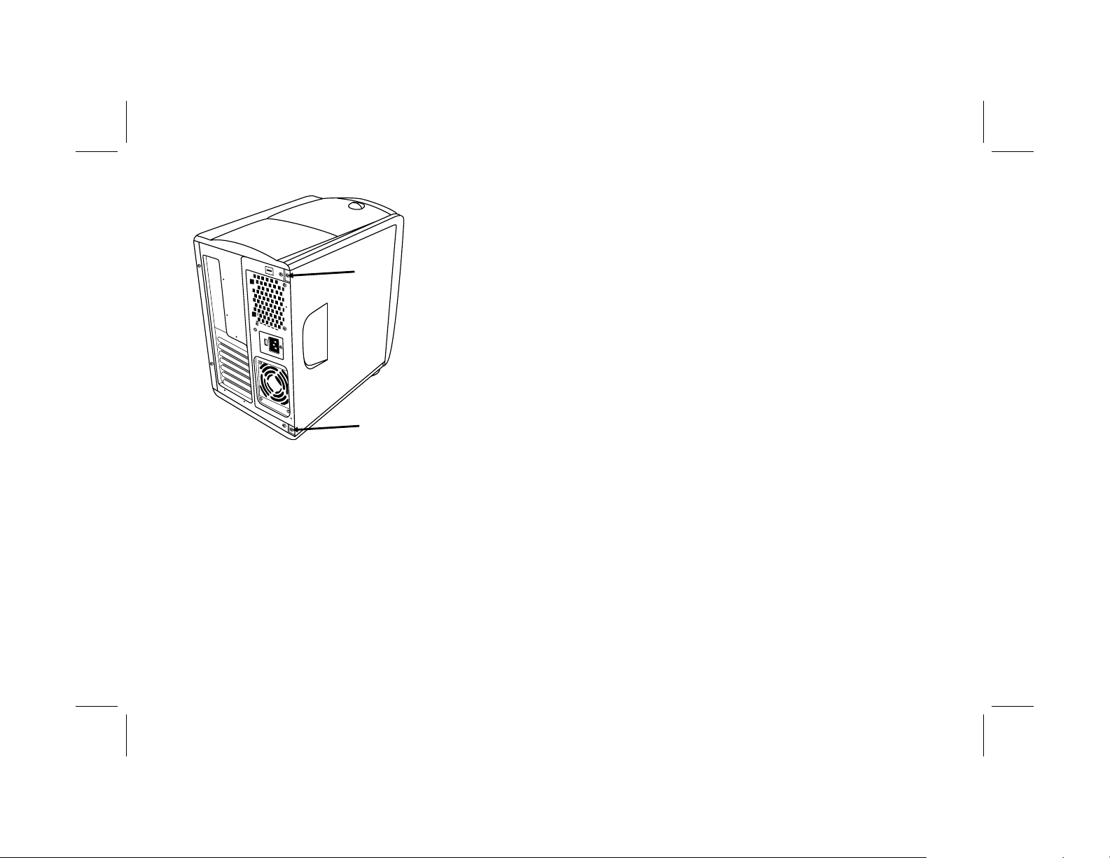
Loosen the two screws on the right side of the
4
back panel. The first time you loosen these
screws you’ll need to use a screwdriver. (These
screws do not detach; they’ll stay on the panel
loosely until you tighten them again.)
English
Filename: ma1rwsc.doc Title: HP-Print2k.dot
Template: HP-Print2K.dot Author: Ann Schmidt Last Saved By: WASSER, Inc.
Revision #: 203 Page: 7 of 70 Printed: 04/27/01 12:42 PM
upgrading and servicing the pc
7
Page 12
Sliding the Drive Cage In and Out
The drive cage must be moved out to allow
access to some components on the motherboard.
You may need to slide the drive cage out in order
to add memory, insert add-in cards, replace an
optical drive, or change the battery.
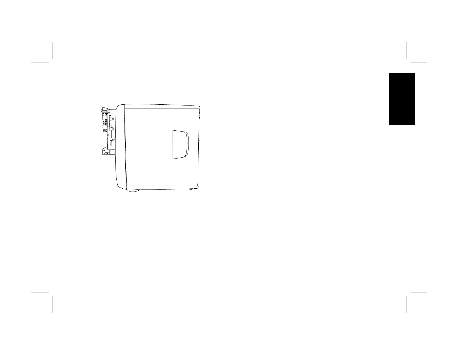
5 Place the fingers of your right hand in the
indentation on the side panel and your thumb
on the back panel.
6 Pull backward on the panel and rotate the
front end of it to the right. It will disengage.
7 Remove the panel and set aside.
8
hp pavilion home pc
Note:
Make sure the computer is turned off and the
modem/phone cable and power cord are
disconnected from the computer.
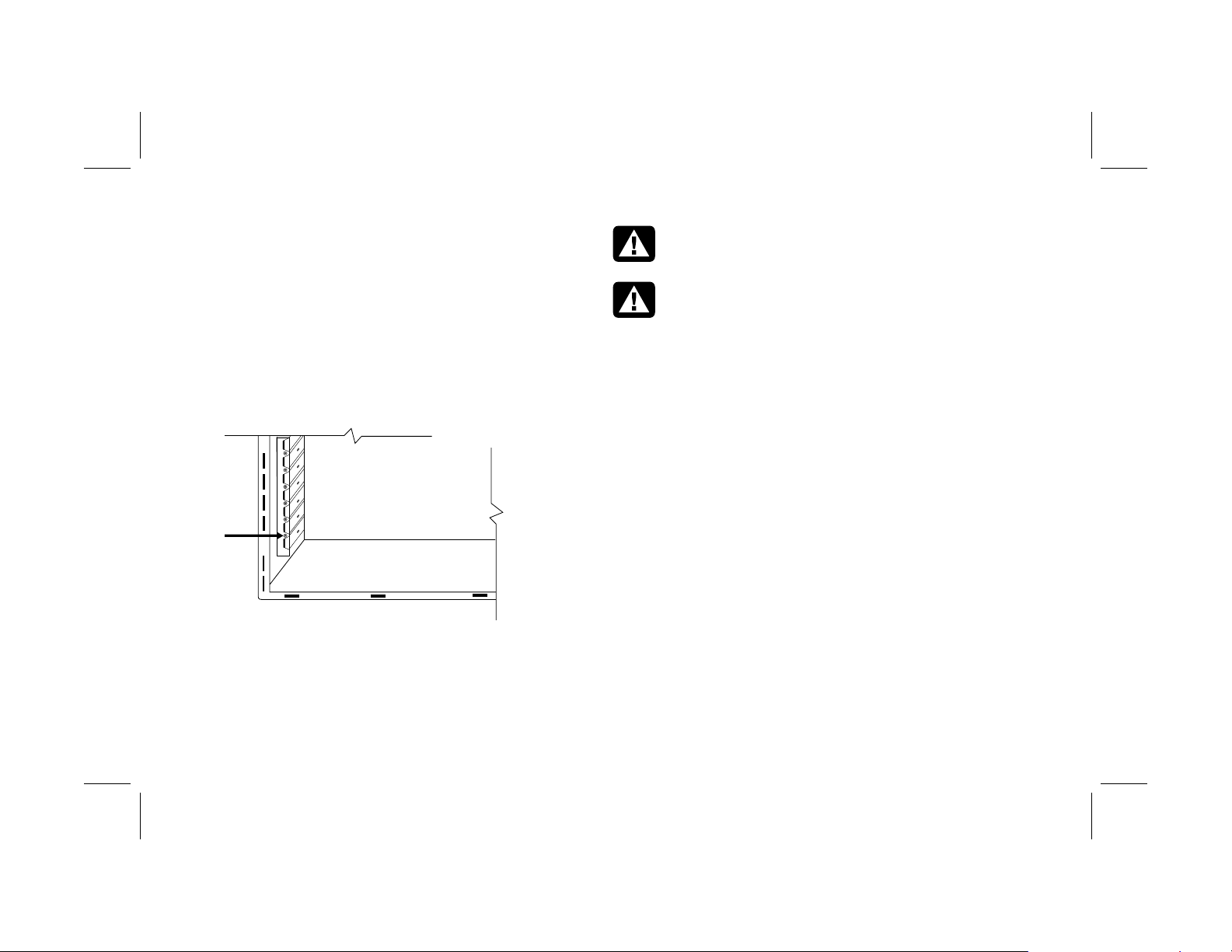
To slide the drive cage out:
1 Remove the front drive cover (see “Removing
the Front Drive Cover” on page 6).
2 Using a #2 Phillips screwdriver, remove the
screw below the diskette drive (A).
Filename: ma1rwsc.doc Title: HP-Print2k.dot
Template: HP-Print2K.dot Author: Ann Schmidt Last Saved By: Jerry C. Stogsdill
Revision #: 198 Page: 8 of 70 Printed: 04/26/01 11:33 AM
Page 13

A
3 Remove the side panel (see “Removing the
Side Panel” on page 7).
4 While facing the front of the computer, reach
under the top edge of the left side of the
chassis and pull the latch (B) out. Continue to
hold the latch in this position while you
complete the next step.
B
C
5 Grasp the top lip of the drive cage (C), and
pull it toward you.
6 Release the latch.
Note:
In order to slide the drive cage out sufficiently,
you may need to disconnect the cables going to
the drives. (On some cables, you may need to
press the locking lever on the connector.) Be
sure to note the placement of these connections;
you will need this information when
reconnecting the cables.
English
Filename: ma1rwsc.doc Title: HP-Print2k.dot
Template: HP-Print2K.dot Author: Ann Schmidt Last Saved By: Jerry C. Stogsdill
Revision #: 198 Page: 9 of 70 Printed: 04/26/01 11:33 AM
upgrading and servicing the pc
9
Page 14

To replace the drive cage:
1 Push against the front panel with your right
hand while pushing against the back panel
with your left hand. The drive cage latch
engages when the drive cage is completely
pushed in.
2 Replace the screw under the diskette drive.
3 Reconnect any power supply cables you may
have disconnected.
Opening the Back Panel Door
You must open the door on the back panel to
access certain components on the motherboard.
(The power supply and fan are attached to the
back panel door.)
1 Remove the side panel (see “Removing the
Side Panel” on page 7).
2 Remove the screws securing the back
panel door.
Note:
10
Filename: ma1rwsc.doc Title: HP-Print2k.dot
Template: HP-Print2K.dot Author: Ann Schmidt Last Saved By: Jerry C. Stogsdill
Revision #: 198 Page: 10 of 70 Printed: 04/26/01 11:33 AM
Make sure the computer is turned off and the
modem/phone cable and power cord are
disconnected from the computer.
hp pavilion home pc
Page 15

3 Swing the door out.
Adding Memory
The motherboard contains 168-pin DIMM
(dual-inline memory module) sockets; the exact
number of sockets depends on which model you
have. You can install these types of DIMMs in the
system:
64 MB SDRAM
128 MB SDRAM
256 MB SDRAM
All installed memory modules must be 168-pin
unbuffered SDRAM (synchronous dynamic
random access memory) DIMMs and compliant
with the Intel
Specification.
The HP Pavilion ships with one or more DIMMs,
but you can replace the existing DIMM(s) with
higher-capacity ones.
®
PC SDRAM Unbuffered DIMM
English
Filename: ma1rwsc.doc Title: HP-Print2k.dot
Template: HP-Print2K.dot Author: Ann Schmidt Last Saved By: Jerry C. Stogsdill
Revision #: 198 Page: 11 of 70 Printed: 04/26/01 11:33 AM
upgrading and servicing the pc
11
Page 16

Installing a DIMM
1 Turn off the computer and all peripherals.
2 Disconnect the modem/phone cable.
3 Disconnect the power cord and all other
attached cables (such as the keyboard, mouse,
and monitor).
4 Remove the side panel (see “Removing the
Side Panel” on page 7).
5 If necessary to reach the DIMM socket, slide
the drive cage out (see “Sliding the Drive
Cage In and Out” on page 8).
6 Gently lay the computer on its side.
7 If necessary to reach the DIMM socket, open
the back panel door (see “Opening the Back
Panel Door” on page 10).
8 Locate the DIMM sockets on the motherboard.
Note: If all of the DIMM sockets are filled, you need to
remove one of the DIMMs (see “Removing a
DIMM” on page 14).
9 Move any cabling out of the way, if necessary.
10 Push down on the two retaining clips on the
ends of the DIMM socket.
11 Holding the new DIMM by its edges only,
remove it from the antistatic packaging. (Avoid
touching the memory chips or the gold
contacts on the DIMM.) The DIMM has two
small notches on the lower edge that fit into
raised bumps in the DIMM socket.
12
Filename: ma1rwsc.doc Title: HP-Print2k.dot
Template: HP-Print2K.dot Author: Ann Schmidt Last Saved By: Jerry C. Stogsdill
Revision #: 198 Page: 12 of 70 Printed: 04/26/01 11:33 AM
hp pavilion home pc
Page 17

12 Hold the DIMM in alignment with the socket,
aligning the notches with the bumps.
To reassemble the computer:
1 If you moved any cabling, restore the cable
connections and routing.
2 If you opened the back panel door, close the
door and replace the screws.
3 If you moved the drive cage, slide the drive
cage back in (see “Sliding the Drive Cage In
and Out” on page 8).
4 Replace the side panel (see “Replacing the
Side Panel” on page 27).
English
13 Push straight down on top of the DIMM until it
5 Reconnect the power cord and all other
is fully seated in the socket. The retaining clips
on the ends of the socket automatically lock
into position when the DIMM is fully seated.
Filename: ma1rwsc.doc Title: HP-Print2k.dot
Template: HP-Print2K.dot Author: Ann Schmidt Last Saved By: Jerry C. Stogsdill
Revision #: 198 Page: 13 of 70 Printed: 04/26/01 11:33 AM
6 Reconnect the modem/phone cable.
7 Turn on the computer and all peripherals.
cables.
upgrading and servicing the pc
13
Page 18

Removing a DIMM
1 Turn off the computer and all peripherals.
2 Disconnect the modem/phone cable.
3 Disconnect the power cord and all other
attached cables (such as the keyboard, mouse,
and monitor).
4 Remove the side panel (see “Removing the
Side Panel” on page 7).
5 If necessary to reach the DIMM socket, slide
the drive cage out (see “Sliding the Drive
Cage In and Out” on page 8).
6 If necessary to reach the DIMM socket, open
the back panel door (see “Opening the Back
Panel Door” on page 10).
7 Gently lay the computer on its side.
8 Locate the DIMM sockets on the motherboard.
9 Move any cabling out of the way, if necessary.
10 Push down on the two retaining clips on the
ends of the DIMM socket until the DIMM pops
out of the socket.
Warning: Do not pull the DIMM out of
the socket. Use the retaining clips to eject
the DIMM.
Avertissement : Ne tirez pas
directement sur le module DIMM.
Servez-vous des clips pour éjecter le
module DIMM.
11 Holding the DIMM by its edges only, lift it
away from the socket. Store it in its antistatic
packaging.
To install a new DIMM in this socket, see
“Installing a DIMM” on page 12.
14
Filename: ma1rwsc.doc Title: HP-Print2k.dot
Template: HP-Print2K.dot Author: Ann Schmidt Last Saved By: Jerry C. Stogsdill
Revision #: 198 Page: 14 of 70 Printed: 04/26/01 11:33 AM
hp pavilion home pc
Page 19

Installing Add-In Cards
At some point, you may add an AGP or PCI card
to the computer to accommodate a new
component, such as a scanner, or to upgrade an
existing card.
You need a #2 Phillips screwdriver and a
medium flat-blade screwdriver. You also need
any software (for example, drivers) supplied with
the card.
Warning: Do not overload the system
by installing add-in cards that draw
excessive current. The system is designed
to provide 2 amps (average) of +5 V
power for each board/card in the
computer. The total +5 V current draw in
a fully loaded system (one with all add-in
card slots filled) must not exceed the total
number of slots multiplied by 2 amps.
Avertissement : Ne surchargez pas
l’ordinateur en installant des cartes
d’extension qui consomment beaucoup de
courant. L’ordinateur est conçu pour
fournir un courant de 2 ampères (en
moyenne), +5 volts, à chaque carte
installée sur l’ordinateur. La
consommation totale de courant de +5 V
sur un ordinateur entièrement chargé
(dont tous les logements de cartes sont
occupés) ne doit pas excéder le nombre
total de supports multiplié par 2 ampères.
To add or replace an add-in card:
1 Turn off the computer and all peripherals.
2 Disconnect the modem/phone cable.
3 Disconnect the power cord and all other
attached cables (such as the keyboard, mouse,
and monitor).
4 Remove the side panel (see “Removing the
Side Panel” on page 7).
English
Filename: ma1rwsc.doc Title: HP-Print2k.dot
Template: HP-Print2K.dot Author: Ann Schmidt Last Saved By: Jerry C. Stogsdill
Revision #: 198 Page: 15 of 70 Printed: 04/26/01 11:33 AM
upgrading and servicing the pc
15
Page 20
5 If necessary to reach the card slots, slide the
drive cage out (see “Sliding the Drive Cage In
and Out” on page 8).
6 Open the back panel door (see “Opening the
Back Panel Door” on page 10).
7 Gently lay the computer on its side.
8 If there is a screw on the expansion slot cover
(A), remove it and set aside.
A
Warning: Be careful of the sharp edges
on the expansion slot cover.
Avertissement : Soyez prudent, car les
bords du couvercle du logement
d’extension sont tranchants.
Note: If replacing a card, first disconnect any external
and/or internal cables attached to the card.
Hold the metal bracket and the far top corner of
the card. Carefully remove the card by pulling
the card straight out of the expansion slot.
10 Insert the new card in the slot and push
straight down. Make sure the card is properly
seated.
11 Reinstall the screw that holds the card to the
back panel.
Note:
9 If you’re adding a new card in a previously
unused slot, you need to remove the expansion
slot cover.
16
Filename: ma1rwsc.doc Title: HP-Print2k.dot
Template: HP-Print2K.dot Author: Ann Schmidt Last Saved By: Jerry C. Stogsdill
Revision #: 198 Page: 16 of 70 Printed: 04/26/01 11:33 AM
hp pavilion home pc
If you didn’t have a screw to remove in step 8
above, you need to purchase a 6-32 x .25-inch
Phillips screw to hold the card to the back
panel.
Page 21

To reassemble the computer:
What Is Plug and Play?
1 Close the back panel door and replace the
screws.
2 If you moved the drive, slide the drive cage
back in (see “Sliding the Drive Cage In and
Out” on page 8).
3 Replace the side panel (see “Replacing the
Side Panel” on page 27).
4 Reconnect the power cord and all other
cables.
5 Reconnect the modem/phone cable.
6 Turn on the computer and all peripherals.
7 Install any software drivers supplied by the
card manufacturer.
“Plug and Play” describes the ability to add and
remove add-in cards, memory, and peripherals
without any special procedures (such as resetting
jumpers and testing for system conflicts). The
system BIOS (basic input/output system) finds
these components and adds them to the system.
You do not have to run the BIOS setup program.
If the New Card or Device Isn’t
Working
Read through the card manufacturer’s installation
instructions, and recheck all connections,
including those to the card, power supply,
keyboard, and monitor. If the problem still exists,
run the BIOS setup program and load the default
settings, and then save and exit.
English
Filename: ma1rwsc.doc Title: HP-Print2k.dot
Template: HP-Print2K.dot Author: Ann Schmidt Last Saved By: Jerry C. Stogsdill
Revision #: 198 Page: 17 of 70 Printed: 04/26/01 11:33 AM
upgrading and servicing the pc
17
Page 22

Adding and Removing
Drives
The drives on your system can be removed and
replaced.
Removing the Hard Drive
To remove the hard drive:
1 Turn off the computer and all peripherals.
2 Disconnect the modem/phone cable.
3 Disconnect the power cord and all other
attached cables (such as the keyboard, mouse,
and monitor).
You need to remove the hard drive from the
chassis if you want to replace it with a highercapacity drive or if you want to safeguard your
data when sending the computer out to be
repaired. If you are replacing the hard drive,
purchase the replacement drive from HP. Refer to
the telephone number of the HP Customer Care
Center on the Support Path card included in the
documentation packet which came with the PC.
18
hp pavilion home pc
4 Remove the front drive cover (see “Removing
the Front Drive Cover” on page 6).
5 Remove the side panel (see “Removing the
Side Panel” on page 7).
6 Slide the drive cage partway out (see “Sliding
the Drive Cage In and Out” on page 8).
7 Disconnect the power and IDE cables attached
to the back of the hard drive. Note the position
of each connector.
Filename: ma1rwsc.doc Title: HP-Print2k.dot
Template: HP-Print2K.dot Author: Ann Schmidt Last Saved By: Jerry C. Stogsdill
Revision #: 198 Page: 18 of 70 Printed: 04/26/01 11:33 AM
Page 23

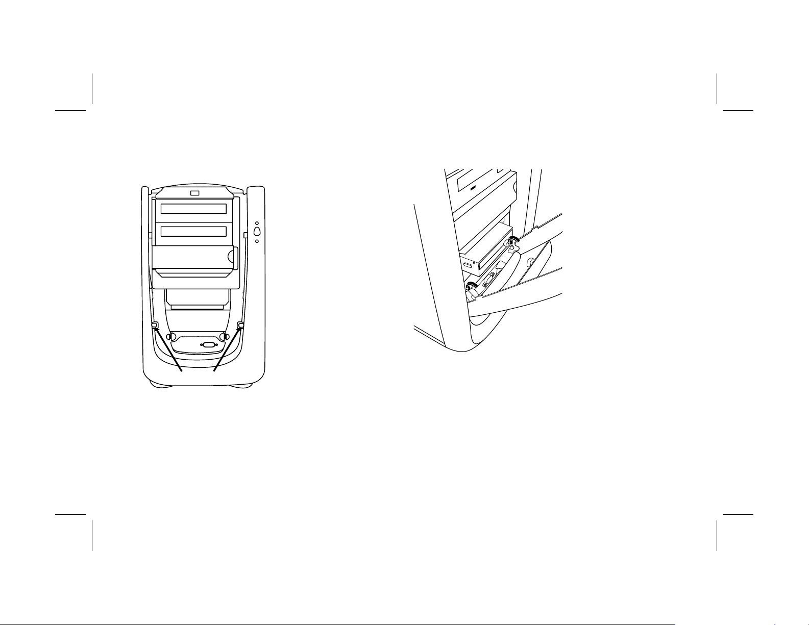
8 Remove the two screws on the front of the hard
drive.
To install the hard drive:
1 Place the new hard drive into the bracket and
secure it with the screws (5).
2 Insert the drive bracket into the drive cage and
push it in until seated.
3 Install the two screws on the front of the hard
drive.
4 Connect the power and IDE cables to the back
of the hard drive.
English
5 Slide the drive cage in (see “Sliding the Drive
9 Pull the hard drive out through the front of the
6 Replace the side panel (see “Replacing the
drive cage.
10 If you are replacing the hard drive, remove the
7 Replace the front drive cover (see “Replacing
screws (5) and lift the drive from the bracket.
Filename: ma1rwsc.doc Title: HP-Print2k.dot
Template: HP-Print2K.dot Author: Ann Schmidt Last Saved By: Jerry C. Stogsdill
Revision #: 198 Page: 19 of 70 Printed: 04/26/01 11:33 AM
Note:
Be sure to connect the IDE cable connector
labeled “Master” to the hard drive.
Cage In and Out” on page 8).
Side Panel” on page 27).
the Front Drive Cover” on page 25).
upgrading and servicing the pc
19
Page 24

8
Reconnect the power cord.
To remove the diskette drive:
9
Reconnect the modem/telephone cable and all
other cables.
10
Turn on the computer and all peripherals.
11
If needed, install Windows.
Replacing the Diskette Drive
If you need to replace the diskette drive, you can
remove the existing drive and install a new one.
To ensure that the drive fits properly into the
HP Pavilion, be sure to purchase the replacement
diskette drive from HP. Refer to your Support Path
card for the telephone number of the
HP Customer Care Center.
1
Turn off the computer and all peripherals.
2
Disconnect the modem/phone cable.
3
Disconnect the power cord and all other
attached cables (such as the keyboard, mouse,
and monitor).
4
Remove the front drive cover (see “Removing
the Front Drive Cover” on page 6).
5
Remove the side panel (see “ Removing the
Side Panel” on page 7).
20
Filename: ma1rwsc.doc Title: HP-Print2k.dot
Template: HP-Print2K.dot Author: Ann Schmidt Last Saved By: WASSER, Inc.
Revision #: 203 Page: 20 of 70 Printed: 04/27/01 12:42 PM
hp pavilion home pc
Page 25

6 Remove the two screws (A) on the side of the
diskette drive.
To install a new diskette drive:
1 Slide the new drive through the diskette drive
bay in the front of the computer, aligning the
screw holes.
English
A
7 Disconnect the power and IDE cables attached
to the back of the diskette drive.
8 Push the diskette drive out through the front of
the computer.
2 Attach the screws.
3 Connect the cables to the back of the drive.
To reassemble the computer:
1 Replace the side panel (see “Replacing the
Side Panel” on page 27).
2 Replace the front drive cover (see “Replacing
the Front Drive Cover” on page 25).
3 Reconnect the power cord and all other
cables.
4 Reconnect the modem/phone cable.
5 Turn on the computer and all peripherals.
upgrading and servicing the pc
21
Filename: ma1rwsc.doc Title: HP-Print2k.dot
Template: HP-Print2K.dot Author: Ann Schmidt Last Saved By: Jerry C. Stogsdill
Revision #: 198 Page: 21 of 70 Printed: 04/26/01 11:33 AM
Page 26

Replacing an Optical Drive
Your computer comes with two optical drives
(CD-ROM, DVD, and/or CD-Writer) that you can
replace or upgrade.
7 Disconnect the power and IDE cables attached
to the back of the optical drive.
8 Remove the two screws (B or C) on the side of
the optical drive.
To remove an optical drive:
1 Turn off the computer and all peripherals.
2 Disconnect the modem/phone cable.
3 Disconnect the power cord and all other
attached cables (such as the keyboard, mouse,
and monitor).
4 Remove the front drive cover (see “Removing
the Front Drive Cover” on page 6).
5 Remove the side panel (see “Removing the
Side Panel” on page 7).
6 Slide the drive cage halfway out (see “Sliding
the Drive Cage In and Out” on page 8).
22
hp pavilion home pc
B
C
Filename: ma1rwsc.doc Title: HP-Print2k.dot
Template: HP-Print2K.dot Author: Ann Schmidt Last Saved By: Jerry C. Stogsdill
Revision #: 198 Page: 22 of 70 Printed: 04/26/01 11:33 AM
Page 27
9 Remove the screw(s) on the other side of the
drive.
Note: If a screw is inaccessible, you’ll need to remove the
drive cage from the chassis. Before removing the
cage, you need to disconnect all the cables that
are attached to the drives in the cage. Be sure to
make note of the cable placements so you’ll be
able to reconnect them.
10 Push the optical drive out through the front of
the drive cage.
To install a new optical drive:
Note:
Make sure the jumper on the new drive is in the CS
(Cable Select) position.
1 Slide the new drive through the optical drive
bay in the drive cage.
2 Connect the cables to the back of the drive.
3 Align the screw holes and attach the screws.
To reassemble the computer:
1 Slide the drive cage back in (see “Sliding the
Drive Cage In and Out” on page 8).
2 Replace the side panel (see “Replacing the
Side Panel” on page 27).
3 Reconnect the power cord and all other
cables.
4 Reconnect the modem/phone cable.
5 Turn on the computer and all peripherals.
6 Install any software drivers supplied by the
drive manufacturer.
English
Filename: ma1rwsc.doc Title: HP-Print2k.dot
Template: HP-Print2K.dot Author: Ann Schmidt Last Saved By: Jerry C. Stogsdill
Revision #: 198 Page: 23 of 70 Printed: 04/26/01 11:33 AM
upgrading and servicing the pc
23
Page 28

Replacing the Battery
A lithium battery on the motherboard provides
backup power for the computer’s timekeeping
capability. The battery has an estimated life
expectancy of seven years.
When the battery starts to weaken, the date and
time may be incorrect. If the battery fails, replace
it with a CR2032 lithium battery (3 volt,
220mAH rating) or an equivalent battery.
Warning: There is a danger of
explosion if the battery is incorrectly
replaced. Replace only with the same, or
equivalent, type of battery. Discard used
batteries according to the manufacturer’s
instructions.
Avertissement : Le remplacement
incorrect de la pile peut provoquer une
explosion. Utilisez uniquement une pile de
même type ou de type équivalent.
Éliminez les piles usées conformément
aux instructions du fabricant.
To replace the battery:
1 Turn off the computer and all peripherals.
2 Disconnect the modem/phone cable.
3 Disconnect the power cord and all other
attached cables (such as the keyboard, mouse,
and monitor).
4 Remove the side panel (see “Removing the
Side Panel” on page 7).
5 If necessary to reach the battery, slide the
drive cage out (see “Sliding the Drive Cage In
and Out” on page 8).
6 If necessary to reach the battery, open the
back panel door (see “Opening the Back
Panel Door” on page 10).
7 Remove any cards that restrict access to the
battery.
8 With a pen or screwdriver, press the metal
latch that holds the battery in its socket. The
battery will pop out.
9 Install the new CR2032 battery in the socket,
with the positive (+) side facing up.
24
Filename: ma1rwsc.doc Title: HP-Print2k.dot
Template: HP-Print2K.dot Author: Ann Schmidt Last Saved By: Jerry C. Stogsdill
Revision #: 198 Page: 24 of 70 Printed: 04/26/01 11:33 AM
hp pavilion home pc
Page 29

To reassemble the computer:
1 Replace any cards that you removed.
2 If you opened the back panel door, close the
door and replace the screws.
3 If you moved the drive cage, slide the drive
cage back in (see “Sliding the Drive Cage In
and Out” on page 8).
Closing the Computer
After you have finished installing memory or
drives, inserting or replacing add-in cards, or
changing the battery, you need to replace the
computer cover(s).
Replacing the Front Drive Cover
English
4 Replace the side panel (see “Replacing the
Side Panel” on page 27).
5 Reconnect the power cord and all other
cables.
6 Reconnect the modem/phone cable.
7 Turn on the computer and all peripherals.
8 Run the BIOS setup program to reset the date
and time.
1 Slide the drive cage back in (see “Sliding the
Drive Cage In and Out” on page 8).
2 Locate the notches near the bottom of the front
drive cover.
upgrading and servicing the pc
25
Filename: ma1rwsc.doc Title: HP-Print2k.dot
Template: HP-Print2K.dot Author: Ann Schmidt Last Saved By: Jerry C. Stogsdill
Revision #: 198 Page: 25 of 70 Printed: 04/26/01 11:33 AM
Page 30
3 Locate the knobs on the front face of the
chassis.
4 Hook the notches onto the knobs.
5 Press the cover toward the chassis until it snaps
into place.
26
Filename: ma1rwsc.doc Title: HP-Print2k.dot
Template: HP-Print2K.dot Author: Ann Schmidt Last Saved By: Jerry C. Stogsdill
Revision #: 198 Page: 26 of 70 Printed: 04/26/01 11:33 AM
hp pavilion home pc
Page 31

Replacing the Side Panel
1 Align the tabs on the bottom of the side panel
with the edge of the frame.
2 Press the panel toward the chassis until the
panel engages.
3 Slide the panel forward until it locks in place.
4 Tighten the two screws on the right side of the
back panel.
English
Filename: ma1rwsc.doc Title: HP-Print2k.dot
Template: HP-Print2K.dot Author: Ann Schmidt Last Saved By: Jerry C. Stogsdill
Revision #: 198 Page: 27 of 70 Printed: 04/26/01 11:33 AM
upgrading and servicing the pc
27
Page 32

28
Filename: ma1rwsc.doc Title: HP-Print2k.dot
Template: HP-Print2K.dot Author: Ann Schmidt Last Saved By: Jerry C. Stogsdill
Revision #: 198 Page: 28 of 70 Printed: 04/26/01 11:33 AM
hp pavilion home pc
Page 33

Contents
Features of the HP Pavilion
home PC.............................................31
Opening the Computer .......................32
Before You Begin ............................................33
Removing the Side Panel..................................34
Sliding the Drive Cage In and Out ....................35
Opening the Back Panel Door ..........................37
Removing the Front Cover ................................38
Adding Memory .................................39
Installing a DIMM............................................40
Removing a DIMM..........................................42
Installing Add-In Cards .......................43
What Is Plug and Play?....................................45
If the New Card or Device Isn’t Working............45
English
Adding and Removing Drives .............46
Removing the Hard Drive................................. 46
Replacing the Diskette Drive.............................48
Replacing an Optical Drive..............................49
Replacing the Battery .........................51
Closing the Computer .........................53
Replacing the Front Cover................................53
Replacing the Side Panel .................................54
Regulatory and Safety Information.....55
ENERGY STAR Compliance..............................58
Operating Specifications .................................65
Filename: ma1rwsc.doc Title: HP-Print2k.dot
Template: HP-Print2K.dot Author: Ann Schmidt Last Saved By: Jerry C. Stogsdill
Revision #: 198 Page: 29 of 70 Printed: 04/26/01 11:33 AM
upgrading and servicing the pc
29
Page 34

30
Filename: ma1rwsc.doc Title: HP-Print2k.dot
Template: HP-Print2K.dot Author: Ann Schmidt Last Saved By: Jerry C. Stogsdill
Revision #: 198 Page: 30 of 70 Printed: 04/26/01 11:33 AM
hp pavilion home pc
Page 35

Features of the
HP Pavilion home PC
On the top of the chassis is a CD holder (A). You
can store the CDs that came with the HP Pavilion
inside this compartment. If you ever need to
reinstall any of the system applications, you will
be able to quickly locate the CDs.
The door located below the CD-ROM drive
covers two drive slots (B). The Zip or CD-Writer
drive, if included with the system, is behind
this door.
To connect components to the front of the PC, flip
up the port cover (C) and plug the cables into the
available connectors. For example, the serial port
(used for a digital camera) is located here.
A
English
B
C
Filename: ma1rwsc.doc Title: HP-Print2k.dot
Template: HP-Print2K.dot Author: Ann Schmidt Last Saved By: Jerry C. Stogsdill
Revision #: 198 Page: 31 of 70 Printed: 04/26/01 11:33 AM
upgrading and servicing the pc
31
Page 36

Opening the Computer
d
Warning: The HP Pavilion is heavy; be
sure to use ergonomically correct lifting
procedures when moving the computer.
Avertissement : L’ordinateur
HP Pavilion est lourd ; suivez des
procédures ergonomiques lorsque vous le
déplacez.
Warning: Electrostatic discharge (ESD)
can damage disk drives, add-in cards,
and other components. If an ESD station is
not available, wear a wrist strap attache
to a metal part of the computer. Place
cards on a conductive foam pad or inside
the conductive wrapper they came in; do
not place the cards on top of the wrapper.
Avertissement : Des décharges
électrostatiques peuvent endommager les
unités de disque, cartes d’extension et
autres composants. Si vous ne disposez
pas d’une station de protection contre les
décharges électrostatiques, portez un
bracelet antistatique relié à une partie
métallique de l’ordinateur. Placez les
cartes sur un tapis en mousse conducteur
ou dans leur emballage, mais ne les
posez jamais sur leur emballage.
Warning: Do not operate the system
with the cover removed. Always replace
the cover before turning on the system.
Avertissement : N’utilisez pas le
système lorsque son capot est ouvert.
Remettez toujours le capot en place avant
de mettre le système sous tension.
32
Filename: ma1rwsc.doc Title: HP-Print2k.dot
Template: HP-Print2K.dot Author: Ann Schmidt Last Saved By: Jerry C. Stogsdill
Revision #: 198 Page: 32 of 70 Printed: 04/26/01 11:33 AM
hp pavilion home pc
Page 37

Before You Begin
Read the following items before attempting to
upgrade or service the computer:
3
These procedures assume familiarity with the
general terminology associated with personal
computers and with the safety practices and
regulatory compliance required for using and
modifying electronic equipment.
3
Set up an equipment log to record the system
model and serial numbers, all installed
options, and other information about the
system. If you need this information, it will be
easier to consult the log than to open up and
examine the system.
3
You need a #2 Phillips screwdriver and a
medium flat-blade screwdriver. HP
recommends that you use an antistatic wrist
strap and a conductive foam pad when
working on the system.
3
Disconnect the system from any
telecommunications links, networks,
or modems, and then disconnect the system
power source before performing any of the
procedures described in this guide. Failure to
do so before you open the system or do any
procedures can result in personal injury or
equipment damage.
To gain access to the inside of the computer, you
need to remove the side panel. For some tasks,
you might also need to slide out the drive cage or
open the back panel door.
Warning:
Safety Information
this document before installing and
connecting your system to the electrical
power system.
Avertissement :
consignes additionnelles de sécurité
fin de ce document avant d’installer et
d’alimenter votre système informatique.
Please read the “
” located at the end of
Prière de lire les
Additional
à la
English
Filename: ma1rwsc.doc Title: HP-Print2k.dot
Template: HP-Print2K.dot Author: Ann Schmidt Last Saved By: WASSER, Inc.
Revision #: 203 Page: 33 of 70 Printed: 04/27/01 12:42 PM
upgrading and servicing the pc
33
Page 38

Removing the Side Panel
You must remove the side panel to access internal
components and to slide the drive cage out. You
need to remove the side panel to add memory,
insert add-in cards, replace drives, or change the
battery.
1 Turn off the computer and all peripherals.
2 Disconnect the modem/phone cable.
3 Disconnect the power cord and all other
attached cables (such as the keyboard, mouse,
and monitor).
4 Loosen the two screws on the right side of the
back panel. The first time you loosen these
screws you’ll need to use a screwdriver. (These
screws do not detach; they’ll stay on the panel
loosely before you tighten them again.)
5 Place the fingers of your right hand in the
indentation on the side panel and your thumb
on the back panel.
6 Pull backward on the panel and rotate the
front end of it to the right. It will disengage.
7 Remove the panel and set aside.
34
Filename: ma1rwsc.doc Title: HP-Print2k.dot
Template: HP-Print2K.dot Author: Ann Schmidt Last Saved By: Jerry C. Stogsdill
Revision #: 198 Page: 34 of 70 Printed: 04/26/01 11:33 AM
hp pavilion home pc
Page 39

Sliding the Drive Cage In and Out
The drive cage must be moved out to allow
access to some components on the motherboard
or to the tabs that release the front panels. You
may need to slide the drive cage out in order to
add memory, insert add-in cards, replace optical
drives, or change the battery.
B
LATCH
English
Note:
Make sure the computer is turned off and the
modem/phone cable and power cord are
disconnected from the computer.
To slide the drive cage out:
1 Remove the side panel (see “Removing the
Side Panel” on page 34).
2 Using a #2 Phillips screwdriver, remove
screw (A) and screw (B) if present.
A
3 With your right hand, reach under the top
edge of the chassis and pull the latch out.
Continue to hold the latch in this position while
you complete the next step.
upgrading and servicing the pc
35
Filename: ma1rwsc.doc Title: HP-Print2k.dot
Template: HP-Print2K.dot Author: Ann Schmidt Last Saved By: Jerry C. Stogsdill
Revision #: 198 Page: 35 of 70 Printed: 04/26/01 11:33 AM
Page 40

4 Insert your left hand between the cabling and
the drive cage. Your hand should be touching
both sides of the drive cage as you push it
toward the front of the computer. Push the
drive cage until it slides partway out.
Note:
The center part of the front cover moves with the
drive cage.
5 Release the latch.
6 Grabbing the top of the drive cage, slide the
cage about halfway out.
Note:
In order to slide the drive cage out sufficiently,
you may need to disconnect the cables going to
the drives. (On some cables, you may need to
press the locking lever on the connector.) Be
sure to note the placement of these connections;
you will need this information when
reconnecting the cables.
To replace the drive cage:
LATCH
DRIVE CAGE
1 Push against the front panel with your right
hand while pushing against the back panel
with your left hand. The drive cage latch
engages when the drive cage is completely
pushed in.
2 Replace the screw (A), and the screw (B) if
present.
3 Reconnect any power supply cables you may
have disconnected.
36
Filename: ma1rwsc.doc Title: HP-Print2k.dot
Template: HP-Print2K.dot Author: Ann Schmidt Last Saved By: Jerry C. Stogsdill
Revision #: 198 Page: 36 of 70 Printed: 04/26/01 11:33 AM
hp pavilion home pc
Page 41

Opening the Back Panel Door
You must open the door on the back panel to
access certain components on the motherboard.
(The power supply and fan are attached to the
back panel door.)
English
Note:
Make sure the computer is turned off and the
modem/phone cable and power cord are
disconnected from the computer.
1 Remove the side panel (see “Removing the
Side Panel” on page 34).
2 Remove the screws securing the back
panel door.
upgrading and servicing the pc
37
Filename: ma1rwsc.doc Title: HP-Print2k.dot
Template: HP-Print2K.dot Author: Ann Schmidt Last Saved By: Jerry C. Stogsdill
Revision #: 198 Page: 37 of 70 Printed: 04/26/01 11:33 AM
Page 42

3 Swing the door out.
Removing the Front Cover
The front of the computer has a cosmetic cover
that you must remove before you can add a new
internal drive into the empty bay. The lower bay
has an insert you must remove in addition to the
cover.
38
hp pavilion home pc
Note:
Make sure the computer is turned off and the
modem/phone cable and power cord are
disconnected from the computer.
1 Remove the side panel (see “Removing the
Side Panel” on page 34).
2 Slide the drive cage out (see “Sliding the Drive
Cage In and Out” on page 35).
Filename: ma1rwsc.doc Title: HP-Print2k.dot
Template: HP-Print2K.dot Author: Ann Schmidt Last Saved By: Jerry C. Stogsdill
Revision #: 198 Page: 38 of 70 Printed: 04/26/01 11:33 AM
Page 43

3 Using a screwdriver or pen, press the two top
tabs on each side of the drive cage. The cover
releases.
Upper Bay &
Front Panel
Lower Bay
4 Remove the cosmetic cover and set aside.
Note:
If you are adding a drive to the lower bay, you
must remove its insert by pressing the two bottom
tabs on each side of the drive cage.
Adding Memory
The motherboard contains 168-pin DIMM
(dual-inline memory module) sockets; the exact
number of sockets depends on which model you
have. You can install these types of DIMMs in the
system:
64 MB SDRAM
128 MB SDRAM
256 MB SDRAM
All installed memory modules must be 168-pin
unbuffered SDRAM (synchronous dynamic
random access memory) DIMMs and compliant
with the Intel
Specification.
The HP Pavilion ships with one or more DIMMs,
but you can replace the existing DIMM(s) with
higher-capacity ones.
®
PC SDRAM Unbuffered DIMM
English
Filename: ma1rwsc.doc Title: HP-Print2k.dot
Template: HP-Print2K.dot Author: Ann Schmidt Last Saved By: Jerry C. Stogsdill
Revision #: 198 Page: 39 of 70 Printed: 04/26/01 11:33 AM
upgrading and servicing the pc
39
Page 44

Installing a DIMM
1 Turn off the computer and all peripherals.
2 Disconnect the modem/phone cable.
3 Disconnect the power cord and all other
attached cables (such as the keyboard, mouse,
and monitor).
4 Remove the side panel (see “Removing the
Side Panel” on page 34).
Note: If all of the DIMM sockets are filled, you need to
remove one of the DIMMs (see “Removing a
DIMM” on page 42).
5 If necessary to reach the DIMM socket, slide
the drive cage out (see “Sliding the Drive
Cage In and Out” on page 35).
6 Gently lay the computer on its side.
7 If necessary to reach the DIMM socket, open
the back panel door (see “Opening the Back
Panel Door” on page 37).
8 Locate the DIMM sockets on the motherboard.
9 Move any cabling out of the way, if necessary.
10 Push down on the two retaining clips on the
ends of the DIMM socket.
11 Holding the new DIMM by its edges only,
remove it from the antistatic packaging. (Avoid
touching the memory chips or the gold
contacts on the DIMM.) The DIMM has two
small notches on the lower edge that fit into
raised bumps in the DIMM socket.
40
Filename: ma1rwsc.doc Title: HP-Print2k.dot
Template: HP-Print2K.dot Author: Ann Schmidt Last Saved By: Jerry C. Stogsdill
Revision #: 198 Page: 40 of 70 Printed: 04/26/01 11:33 AM
hp pavilion home pc
Page 45

12 Hold the DIMM in alignment with the socket,
aligning the notches with the bumps.
To reassemble the computer:
1 If you moved any cabling, restore the cable
connections and routing.
2 If you moved the drive cage, slide the drive
cage back in (see “Sliding the Drive Cage In
and Out” on page 35).
3 If you opened the back panel door, close the
door and replace the screws.
4 Replace the side panel (see “Replacing the
Side Panel” on page 54).
English
13 Push straight down on top of the DIMM until it
5 Reconnect the power cord and all other
is fully seated in the socket. The retaining clips
on the ends of the socket automatically lock
into position when the DIMM is fully seated.
Filename: ma1rwsc.doc Title: HP-Print2k.dot
Template: HP-Print2K.dot Author: Ann Schmidt Last Saved By: Jerry C. Stogsdill
Revision #: 198 Page: 41 of 70 Printed: 04/26/01 11:33 AM
6 Reconnect the modem/phone cable.
7 Turn on the computer and all peripherals.
cables.
upgrading and servicing the pc
41
Page 46

Removing a DIMM
1 Turn off the computer and all peripherals.
2 Disconnect the modem/phone cable.
3 Disconnect the power cord and all other
attached cables (such as the keyboard, mouse,
and monitor).
4 Remove the side panel (see “Removing the
Side Panel” on page 34).
5 If necessary to reach the DIMM socket, slide
the drive cage out (see “Sliding the Drive
Cage In and Out” on page 35).
6 If necessary to reach the DIMM socket, open
the back panel door (see “Opening the Back
Panel Door” on page 37).
7 Gently lay the computer on its side.
8 Locate the DIMM sockets on the motherboard.
9 Move any cabling out of the way, if necessary.
10 Push down on the two retaining clips on the
ends of the DIMM socket until the DIMM pops
out of the socket.
Warning: Do not pull the DIMM out of
the socket. Use the retaining clips to eject
the DIMM.
Avertissement : Ne tirez pas
directement sur le module DIMM.
Servez-vous des clips pour éjecter le
module DIMM.
11 Holding the DIMM by its edges only, lift it
away from the socket. Store it in its antistatic
packaging.
To install a new DIMM in this socket, see
“Installing a DIMM” on page 40.
42
Filename: ma1rwsc.doc Title: HP-Print2k.dot
Template: HP-Print2K.dot Author: Ann Schmidt Last Saved By: Jerry C. Stogsdill
Revision #: 198 Page: 42 of 70 Printed: 04/26/01 11:33 AM
hp pavilion home pc
Page 47

Installing Add-In Cards
At some point, you may add an AGP or PCI card
to the computer to accommodate a new
component, such as a scanner, or to upgrade an
existing card.
You need a #2 Phillips screwdriver and a
medium flat-blade screwdriver. You also need
any software (for example, drivers) supplied with
the card.
Warning: Do not overload the system
by installing add-in cards that draw
excessive current. The system is designed
to provide 2 amps (average) of +5 V
power for each board/card in the
computer. The total +5 V current draw in
a fully loaded system (one with all add-in
card slots filled) must not exceed the total
number of slots multiplied by 2 amps.
Avertissement : Ne surchargez pas
l’ordinateur en installant des cartes
d’extension qui consomment beaucoup de
courant. L’ordinateur est conçu pour
fournir un courant de 2 ampères (en
moyenne), +5 volts, à chaque carte
installée sur l’ordinateur. La
consommation totale de courant de +5 V
sur un ordinateur entièrement chargé
(dont tous les logements de cartes sont
occupés) ne doit pas excéder le nombre
total de supports multiplié par 2 ampères.
To add or replace an add-in card:
1 Turn off the computer and all peripherals.
2 Disconnect the modem/phone cable.
3 Disconnect the power cord and all other
attached cables (such as the keyboard, mouse,
and monitor).
English
Filename: ma1rwsc.doc Title: HP-Print2k.dot
Template: HP-Print2K.dot Author: Ann Schmidt Last Saved By: Jerry C. Stogsdill
Revision #: 198 Page: 43 of 70 Printed: 04/26/01 11:33 AM
upgrading and servicing the pc
43
Page 48

4 Remove the side panel (see “Removing the
Side Panel” on page 34).
5 If necessary to reach the card slots, slide the
drive cage out (see “Sliding the Drive Cage In
and Out” on page 35).
6 Open the back panel door (see “Opening the
Back Panel Door” on page 37).
7 Gently lay the computer on its side.
8 If there is a screw on the expansion slot cover
(A), remove it and set aside.
A
Warning: Be careful of the sharp edges
on the expansion slot cover.
Avertissement : Soyez prudent, car les
bords du couvercle du logement
d’extension sont tranchants.
Note: If replacing a card, first disconnect any external
and/or internal cables attached to the card.
Hold the metal bracket and the far top corner of
the card. Carefully remove the card by pulling
the card straight out of the expansion slot.
10 Insert the new card in the slot and push
straight down. Make sure the card is properly
seated.
11 Reinstall the screw that holds the card to the
back panel.
Note:
9 If you’re adding a new card in a previously
unused slot, you need to remove the expansion
slot cover.
44
Filename: ma1rwsc.doc Title: HP-Print2k.dot
Template: HP-Print2K.dot Author: Ann Schmidt Last Saved By: Jerry C. Stogsdill
Revision #: 198 Page: 44 of 70 Printed: 04/26/01 11:33 AM
hp pavilion home pc
If you didn’t have a screw to remove in step 8,
you need to purchase a 6-32 x .25-inch Phillips
screw to hold the card to the back panel.
Page 49

To reassemble the computer:
What Is Plug and Play?
1 Close the back panel door and replace the
screws.
2 If you moved the drive cage, slide the drive
cage back in (see “Sliding the Drive Cage In
and Out” on page 35).
3 Replace the side panel (see “Replacing the
Side Panel” on page 54).
4 Reconnect the power cord and all other
cables.
5 Reconnect the modem/phone cable.
6 Turn on the computer and all peripherals.
7 Install any software drivers supplied by the
card manufacturer.
“Plug and Play” describes the ability to add and
remove add-in cards, memory, and peripherals
without any special procedures (such as resetting
jumpers and testing for system conflicts). The
system BIOS (basic input/output system) finds
these components and adds them to the system.
You do not have to run the BIOS setup program.
If the New Card or Device Isn’t
Working
Read through the card manufacturer’s installation
instructions, and recheck all connections,
including those to the card, power supply,
keyboard, and monitor. If the problem still exists,
run the BIOS setup program and load the default
settings, and then save and exit.
English
Filename: ma1rwsc.doc Title: HP-Print2k.dot
Template: HP-Print2K.dot Author: Ann Schmidt Last Saved By: Jerry C. Stogsdill
Revision #: 198 Page: 45 of 70 Printed: 04/26/01 11:33 AM
upgrading and servicing the pc
45
Page 50

Adding and Removing
Drives
The drives on your system can be removed and
replaced.
Removing the Hard Drive
To remove the hard drive:
1 Turn off the computer and all peripherals.
2 Disconnect the modem/telephone cable.
3 Disconnect the power cord and all other
attached cables (such as the keyboard, mouse,
and monitor).
You need to remove the hard drive from the
chassis if you want to replace it with a highercapacity disk drive or if you want to safeguard
your data when sending the computer out to be
repaired. If you are replacing the hard drive,
purchase the replacement drive from HP. Refer to
the telephone number of the HP Customer Care
Center on the Support Path card included in the
documentation packet which came with the PC.
46
hp pavilion home pc
4 Remove the side panel (see “Removing the
Side Panel” on page 34).
5 Slide the drive cage out partway (see “Sliding
the Drive Cage In and Out” on page 35).
6 Disconnect the power and IDE cables attached
to the back of the hard drive. Note the position
of each cable.
Note:
In order to slide the drive cage out sufficiently,
you may need to disconnect the cables going to
the drives. (On some cables, you may need to
press the locking lever on the connector.) Be
sure to note the placement of these connections;
you will need this information when
reconnecting the cables.
Filename: ma1rwsc.doc Title: HP-Print2k.dot
Template: HP-Print2K.dot Author: Ann Schmidt Last Saved By: Jerry C. Stogsdill
Revision #: 198 Page: 46 of 70 Printed: 04/26/01 11:33 AM
Page 51

7 Disconnect all the cables from the drive cage.
Slide the drive cage completely out of the
chassis and place it on its side.
8 Remove the two screws on each side that hold
the hard drive bracket.
9 Slide the drive bracket out the back of the
drive cage.
10 Remove the two screws that secure the drive to
the bracket. Lift the drive from the bracket.
To install the new hard drive:
4 Place the drive cage back into the chassis with
the cage extended out partway.
5 Connect all the cables you previously
removed.
Note:
Be sure to connect the IDE cable connector
labeled ‘Master’ to the hard drive.
6 Slide the drive cage in (see “Sliding the Drive
Cage In and Out” on page 35).
7 Replace the side panel (see “Replacing the
Side Panel” on page 54).
English
1 Place the new hard drive into the bracket and
secure it with two screws.
2 Slide the bracket into the back of the
drive cage.
3 Align the screw holes and install the two
8 Connect the power cord.
9 Connect the modem/telephone cable and all
other cables.
10 Turn on the computer and all peripherals.
11 If needed, install Windows.
screws on each side.
Filename: ma1rwsc.doc Title: HP-Print2k.dot
Template: HP-Print2K.dot Author: Ann Schmidt Last Saved By: Jerry C. Stogsdill
Revision #: 198 Page: 47 of 70 Printed: 04/26/01 11:33 AM
upgrading and servicing the pc
47
Page 52

Replacing the Diskette Drive
If you need to replace the diskette drive, you can
remove the existing drive and install a new one.
To ensure that the drive fits properly into the
HP Pavilion, be sure to purchase the replacement
diskette drive from HP. Refer to your Support Path
card for the telephone number of the
HP Customer Care Center.
To remove the diskette drive:
1 Turn off the computer and all peripherals.
2 Disconnect the modem/phone cable.
5 Remove the two screws (A) on the side of the
diskette drive.
A
3 Disconnect the power cord and all other
attached cables (such as the keyboard, mouse,
6 Slide the drive cage out partway (see “Sliding
the Drive Cage In and Out” on page 35).
and monitor).
7 Disconnect the power and IDE cables attached
4 Remove the side panel (see “Removing the
to the back of the diskette drive.
Side Panel” on page 34).
8 Pull the diskette drive out through the back of
the drive cage.
48
Filename: ma1rwsc.doc Title: HP-Print2k.dot
Template: HP-Print2K.dot Author: Ann Schmidt Last Saved By: Jerry C. Stogsdill
Revision #: 198 Page: 48 of 70 Printed: 04/26/01 11:33 AM
hp pavilion home pc
Page 53

To install a new diskette drive:
Replacing an Optical Drive
1 Slide the new drive through the back of the
drive cage into the diskette drive bay, aligning
the screw holes.
2 Attach the screws.
3 Connect the cables to the back of the drive.
To reassemble the computer:
1 Slide the drive cage in (see “Sliding the Drive
Cage In and Out” on page 35).
2 Replace the side panel (see “Replacing the
Side Panel” on page 54).
3 Reconnect the power cord.
4 Reconnect the modem/phone cable and all
other cables.
5 Turn on the computer and all peripherals.
Your computer comes with two optical drives
(CD-ROM, DVD, and/or CD-Writer) that you can
replace or upgrade.
To remove an optical drive:
1 Turn off the computer and all peripherals.
2 Disconnect the modem/phone cable.
3 Disconnect the power cord and all other
attached cables (such as the keyboard, mouse,
and monitor).
4 Remove the side panel (see “Removing the
Side Panel” on page 34).
5 Slide the drive cage halfway out (see “Sliding
the Drive Cage In and Out” on page 35).
6 Disconnect the power and IDE cables attached
to the back of the optical drive.
English
Filename: ma1rwsc.doc Title: HP-Print2k.dot
Template: HP-Print2K.dot Author: Ann Schmidt Last Saved By: Jerry C. Stogsdill
Revision #: 198 Page: 49 of 70 Printed: 04/26/01 11:33 AM
upgrading and servicing the pc
49
Page 54

7 Remove the two screws (B or C) on the side of
the optical drive.
B
C
8 Remove the screw(s) on the other side of the
drive.
50
Filename: ma1rwsc.doc Title: HP-Print2k.dot
Template: HP-Print2K.dot Author: Ann Schmidt Last Saved By: Jerry C. Stogsdill
Revision #: 198 Page: 50 of 70 Printed: 04/26/01 11:33 AM
hp pavilion home pc
Note: If a screw is inaccessible, you’ll need to remove the
9 Push the optical drive through the front of the
drive cage.
drive cage from the chassis. Before removing the
cage, you need to disconnect all the cables that
are attached to the drives in the cage. Be sure to
make note of the cable placements so you’ll be
able to reconnect them.
Page 55

To install a new optical drive:
Replacing the Battery
Note:
Make sure the jumper on the new drive is in the CS
(Cable Select) position.
1 Slide the new drive through the optical drive
bay in the drive cage.
2 Connect the cables to the back of the drive.
3 Align the screw holes and attach the screws.
To reassemble the computer:
1 Slide the drive cage back in (see “Sliding the
Drive Cage In and Out” on page 35).
2 Replace the side panel (see “Replacing the
Side Panel” on page 54).
3 Reconnect the power cord and all other
cables.
4 Reconnect the modem/phone cable.
5 Turn on the computer and all peripherals.
6 Install any software drivers supplied by the
drive manufacturer.
A lithium battery on the motherboard provides
backup power for the computer’s timekeeping
capability. The battery has an estimated life
expectancy of seven years.
When the battery starts to weaken, the date and
time may be incorrect. If the battery fails, replace
it with a CR2032 lithium battery (3 volt,
220mAH rating) or an equivalent battery.
Warning: There is a danger of
explosion if the battery is incorrectly
replaced. Replace only with the same, or
equivalent, type of battery. Discard used
batteries according to the manufacturer’s
instructions.
Avertissement : Le remplacement
incorrect de la pile peut provoquer une
explosion. Utilisez uniquement une pile de
même type ou de type équivalent.
Éliminez les piles usées conformément
aux instructions du fabricant.
English
Filename: ma1rwsc.doc Title: HP-Print2k.dot
Template: HP-Print2K.dot Author: Ann Schmidt Last Saved By: Jerry C. Stogsdill
Revision #: 198 Page: 51 of 70 Printed: 04/26/01 11:33 AM
upgrading and servicing the pc
51
Page 56

To replace the battery:
1 Turn off the computer and all peripherals.
2 Disconnect the modem/phone cable.
3 Disconnect the power cord and all other
attached cables (such as the keyboard, mouse,
and monitor).
4 Remove the side panel (see “Removing the
Side Panel” on page 34).
5 If necessary to reach the battery, slide the
drive cage out (see “Sliding the Drive Cage In
and Out” on page 35).
6 If necessary to reach the battery, open the
back panel door (see “Opening the Back
Panel Door” on page 37).
7 Gently lay the computer on its side.
8 Remove any cards that restrict access to the
battery.
9 With a pen or screwdriver, press the metal
latch that holds the battery in its socket. The
battery will pop out.
10 Install the new CR2032 battery in the socket,
with the positive (+) side facing up.
52
Filename: ma1rwsc.doc Title: HP-Print2k.dot
Template: HP-Print2K.dot Author: Ann Schmidt Last Saved By: Jerry C. Stogsdill
Revision #: 198 Page: 52 of 70 Printed: 04/26/01 11:33 AM
hp pavilion home pc
Page 57

To reassemble the computer:
1 Replace any cards that you removed.
2 If you opened the back panel door, close the
door and replace the screws.
3 If you moved the drive cage, slide the drive
cage back in (see “Sliding the Drive Cage In
and Out” on page 35).
Closing the Computer
After you have finished installing memory or
drives, inserting or replacing add-in cards, or
changing the battery, you need to replace the
computer cover(s).
Replacing the Front Cover
English
4 Replace the side panel (see “Replacing the
Side Panel” on page 54).
5 Reconnect the power cord and all other
cables.
6 Reconnect the modem/phone cable.
7 Turn on the computer and all peripherals.
8 Run the BIOS setup program to reset the date
and time.
If you installed a removable-media drive, do not
replace the cosmetic front cover. For other types
of drives, you can replace the cover if you
choose.
1 Before sliding the drive cage back in or
replacing the side panel, position the cover in
its original location.
2 Push on the cover until the tabs automatically
click into place.
upgrading and servicing the pc
53
Filename: ma1rwsc.doc Title: HP-Print2k.dot
Template: HP-Print2K.dot Author: Ann Schmidt Last Saved By: Jerry C. Stogsdill
Revision #: 198 Page: 53 of 70 Printed: 04/26/01 11:33 AM
Page 58

Replacing the Side Panel
1 Align the tabs on the bottom of the side panel
with the edge of the frame.
2 Press the panel toward the chassis until the
panel engages.
3 Slide the panel forward until it locks in place.
4 Tighten the two screws on the right side of the
back panel.
54
Filename: ma1rwsc.doc Title: HP-Print2k.dot
Template: HP-Print2K.dot Author: Ann Schmidt Last Saved By: Jerry C. Stogsdill
Revision #: 198 Page: 54 of 70 Printed: 04/26/01 11:33 AM
hp pavilion home pc
Page 59

Regulatory and Safety
Information
Declaration of Conformity
Manufacturer’s Name: Hewlett-Packard Company
Manufacturer’s Address: 10500 Ridgeview Ct.
declares that the product
Product Name: HP Pavilion Multimedia Personal Computer
Model Number(s): XL9ZZ, XP9ZZ (Z is any number 0–9)
Product Options: All
conforms to the following Product Specifications:
Safety: UL 1950
EMC: FCC Title 47 CFR, Part 15 Class B
Cupertino, CA 95015-4010
USA
System
89XXY (X is any number 0–9, Y is any
alphanumeric character or blank)
1)
/ICES-003, Issue 2
Supplementary Information:
This Device complies with Part 15 of the FCC Rules. Operation is
1)
subject to the following two conditions: (1) this device may not
cause harmful interference, and (2) this device must accept any
interference received, including interference that may cause
undesired operation.
Hardware Quality Engineering Manager
Cupertino, CA, USA May, 2001
For Regulatory Compliance Information ONLY, contact:
North America
Contact:
Hardware Quality Engineering Manager
Hewlett-Packard, HPD
10500 Ridgeview Ct.
Cupertino, CA 95015-4010
USA
(Phone: 408-343-5000)
English
Filename: ma1rwsc.doc Title: HP-Print2k.dot
Template: HP-Print2K.dot Author: Ann Schmidt Last Saved By: Jerry C. Stogsdill
Revision #: 198 Page: 55 of 70 Printed: 04/26/01 11:33 AM
upgrading and servicing the pc
55
Page 60

FCC Regulatory and Safety
quip
e
t
y
Information (USA Only)
Federal Communications Commission (FCC) Radio
Frequency Interference Statement
Warning: This equipment has been tested
and found to comply with the limits for a
Class B digital device, pursuant to Part 15
of the FCC Rules. These limits are designed
to provide reasonable protection against
harmful interference in a residential
installation. This equipment generates,
uses, and can radiate radio frequency
energy and, if not installed and used in
accordance with the instructions,
may cause harmful interf er ence to radio
communications. However, there is no
guarantee that interference will not occur
in a particular installation. If this
e
ment does cause harmful interferenc
to radio or television reception, which can
be determined by turning the equipment
off and on, the user is encouraged to
correct the interference by one or more of
the following measures:
Reorient or relocate the receiving
antenna.
Increase the separation between the
equipment and the receiver.
Connect the equipment into an outlet tha
is on a circuit different from the receiver.
Consult the dealer or an experienced
radio/TV technician for help.
Hewlett-Packard’s s
stem RFI and Radiated
Immunity tests were conducted with
HP-supported peripheral devices and
HP-shielded cables, such as those you
receive with your system. Changes or
modifications not expressly approved by
Hewlett-Packard could void the user’s
authority to operate the equipment. To
comply with the limits for an FCC Class B
computing device, always use shielded
signal cables and the power cord supplied
with this unit.
56
Filename: ma1rwsc.doc Title: HP-Print2k.dot
Template: HP-Print2K.dot Author: Ann Schmidt Last Saved By: Jerry C. Stogsdill
Revision #: 198 Page: 56 of 70 Printed: 04/26/01 11:33 AM
hp pavilion home pc
Page 61

Consumer Information and FCC
Requirements
Telephone Connection
This equipment complies with Part 68 of the Federal
Communications Commission rules. These rules permit this
device to be directly connected to the telephone network.
Standardized jacks are used for these connections. This
equipment should not be used on party lines or coin lines.
If this device is malfunctioning, it may also cause harm to
the telephone network; this device should be disconnected
until the source of the problem can be determined and
until it has been repaired. If this is not done, the
telephone company may temporarily disconnect your
service.
The telephone company may make changes in its
technical operations and procedures. If such changes
affect the compatibility or use of this device, the telephone
company is required to give adequate notice of the
changes.
If the telephone company requests information on what
equipment is connected to their lines, inform them of:
a The telephone number this unit is connected to
b The ringer equivalence number
c The USOC jack required: RJ-11C
d The FCC Registration Number
Items (b) and (c) are indicated on the label. The ringer
equivalence number (REN) is used to determine how
many devices can be connected to your telephone line.
In most areas, the sum of the RENs on any one line should
not exceed five (5.0). If too many devices are attached,
they may not ring properly.
In the event of equipment malfunction, Hewlett-Packard or
an authorized HP Personal Computer Dealer Repair
Center should perform all repairs. It is the responsibility of
users requiring service to report the problem to HP’s
Home Products Division, or to one of our authorized
agents. Service can be obtained by calling the
HP Customer Care Center at 208-323-4663
(United States).
English
Filename: ma1rwsc.doc Title: HP-Print2k.dot
Template: HP-Print2K.dot Author: Ann Schmidt Last Saved By: Jerry C. Stogsdill
Revision #: 198 Page: 57 of 70 Printed: 04/26/01 11:33 AM
upgrading and servicing the pc
57
Page 62

Statement of Fax Branding
The Consumer Protection Act of 1991 makes it unlawful for
any person to use a computer or other electronic device to
send any message via telephone fax machine, unless it
clearly contains: a margin at the top or bottom of each
transmitted page or on the first page of the transmission, the
date and time it is sent, identification of the business or other
entity, or individual sending the message, and the telephone
number of the sending machine or such business, entity, or
individual.
Canada Department of
Communications (DOC) Notice
Telephone Connection
The Canada Department of Communications label identifies
certified equipment. This certification means that the
equipment meets certain telecommunications network
protective, operational, and safety requirements. The
department does not guarantee the equipment will operate
to the user’s satisfaction.
ENERGY STAR Compliance
Hewlett-Packard Pavilion PCs and monitors marked with the
ENERGY STAR logo comply with the U.S. Environmental
Protection Agency’s ENERGY STAR guidelines for energy
efficiency. For information on changing power management
features, refer to “Putting the Computer into Standby and
Hibernation Mode” in the Quick Start Guide.
ENERGY STAR is a U.S. registered service mark of the
United States Environmental Protection Agency.
58
Filename: ma1rwsc.doc Title: HP-Print2k.dot
Template: HP-Print2K.dot Author: Ann Schmidt Last Saved By: Jerry C. Stogsdill
Revision #: 198 Page: 58 of 70 Printed: 04/26/01 11:33 AM
hp pavilion home pc
Before installing this equipment, the user should ensure it
is permissible to connect it to the facilities of the local
communications company. The equipment must be installed
using an acceptable method of connection. In some cases,
the company’s inside wiring associated with a single line
individual service may be extended by means of a certified
connector assembly (telephone extension cord). The
customer should be aware that compliance with the above
conditions may not prevent degradation of service in some
situations.
Repairs to certified equipment should be made by an
authorized Canadian maintenance facility designated by the
supplier. Any repairs or alterations made by the user to this
equipment, or equipment malfunctions, may give the
telecommunications company cause to request that the user
disconnect the equipment.
Page 63

Users should ensure, for their own protection, that the
electrical ground connections of the power utility, telephone
lines, and internal metallic water pipe systems, if present,
are connected together. This precaution may be particularly
important in rural areas.
Warning: Users should not attempt to
make such connections themselves, but
should contact the appropriate electrical
inspection authority or electrician, as
appropriate.
Avertissement : L’utilisateur ne devrait pas
tenter de faire ces connexions lui-même
mais devrait utiliser les services
de l’organisme approprié d’inspection des
installations électriques ou d’un électricien,
selon le cas.
Warning: The Load Number .9 assigned to
each terminal device denotes the
percentage of the total load to be
connected to a telephone loop; this is used
by the device to prevent overloading. The
termination on a loop may consist of any
combination of devices, subject only to the
requirement that the sum of the Load
Numbers does not exceed 100.
Avertissement : La valeur de charge .9
attribuée à chaque élément terminal
indique le pourcentage de la charge totale
pouvant être connecté à une boucle
téléphonique. Cette valeur est utilisée pour
éviter les surcharges. La terminaison d’une
boucle peut être constituée d’une
combinaison quelconque d’équipements,
dans la mesure où la somme des valeurs
de charge ne dépasse pas 100.
DOC Statement (Canada Only)
This Class B digital apparatus meets all requirements of the
Canadian Interference-Causing Equipment Regulations.
Cet appareil numérique de la classe B respecte toutes les
exigences du Règlement sur le matériel brouilleur du
Canada.
English
Filename: ma1rwsc.doc Title: HP-Print2k.dot
Template: HP-Print2K.dot Author: Ann Schmidt Last Saved By: Jerry C. Stogsdill
Revision #: 198 Page: 59 of 70 Printed: 04/26/01 11:33 AM
upgrading and servicing the pc
59
Page 64

Additional Safety Information
A
y
p
This product has not been evaluated for connection to an
“IT” power system (an AC distribution system with no direct
connection to earth, according to IEC 60950).
AC Power Safety Warning
Warning: Install the computer near an AC
outlet. The AC power cord is your
HP Pavilion’s main AC disconnecting device
and must be easily accessible at all times.
For your safety, the power cord provided
with your system has a grounded plug.
lways use the power cord with a properl
grounded wall outlet, to avoid the risk of
electrical shock.
Warning: Your system is provided with a
voltage select switch for use in a 115 or
230 Vac power system. The voltage select
switch has been pre-set to the correct
voltage setting for use in the particular
country where it was initially sold.
Changing the voltage select switch to the
incorrect
void any implied warranty.
osition can damage your PC and
Warning: To reduce the possibility of an
electric shock from the telephone network,
plug your computer into the AC outlet
before connecting it to the telephone line.
Also, disconnect the telephone line be fore
unplugging your computer from the
AC power outlet.
Warning: Always disconnect the modem
cord from the telephone system before
installing or removing your computer
cover.
Warning: Do not operate the computer
with the cover removed.
Warning: The power supply is not userserviceable. To prevent damage to the
power supply, have a qualified person
repair or replace it. All other components
are user-serviceable.
Warning: Electrostatic discharge (ESD) can
damage disk drives, add-in cards, and
other components. If an ESD station is not
available, wear a wrist strap attached to a
metal part of the computer. Place cards on
a conductive foam pad or inside the card
wrapper, if possible, but never on the card
wrapper.
60
Filename: ma1rwsc.doc Title: HP-Print2k.dot
Template: HP-Print2K.dot Author: Ann Schmidt Last Saved By: Jerry C. Stogsdill
Revision #: 198 Page: 60 of 70 Printed: 04/26/01 11:33 AM
hp pavilion home pc
Page 65

Warning: For your safety, always unplug
y
m
p
s
p
f
n
j
e
déconnectez votre ligne téléphonique avant
the s
stem from its power source and fro
any telecommunications systems (such as
phone lines), networks, or modems before
performing any of the procedures
described in this guide. Failure to do so
may result in personal injury or equipment
damage. Hazardous voltage levels are
inside the
product.
Avertissement : Installez l’ordinateur à
proximité d’une prise c.a. Le cordon
d’alimentation c.a. est le
de déconnexion de l’ordinateur HP Pavilio
et doit toujours être facilement accessible.
Pour votre sécurité, le cordon
d’alimentation fourni avec votre système
possède une prise avec mise à la terre.
Branchez tou
murale avec mise à la terre, afin d’éviter
les risques d’électrocution.
ower supply and modem of thi
rincipal dispositi
ours le cordon dans une pris
Avertissement : Votre système est doté
d’un commutateur de sélection de tension
(115 ou 230 volts c.a.). Ce commutateur a
été placé sur la tension appropriée pour le
pays dans lequel l’équipement est
initialement vendu. Mettre le commutateur
à la mauvaise position peut endommager
l’ordinateur et annuler toute garantie
implicite.
Avertissement : Pour réduire les risques de
choc électrique en provenance du réseau
téléphonique, branchez votre ordinateur
dans une prise c.a. avant de le connecter à
une ligne téléphonique. En outre,
de débrancher votre ordinateur de la
prise c.a.
Avertissement : Débranchez la carte
modem du réseau téléphonique avant
d’installer ou d’enlever le couvercle de
votre ordinateur.
Avertissement : N’utilisez pas l’ordinateur
lorsque le capot est enlevé.
English
Filename: ma1rwsc.doc Title: HP-Print2k.dot
Template: HP-Print2K.dot Author: Ann Schmidt Last Saved By: Jerry C. Stogsdill
Revision #: 198 Page: 61 of 70 Printed: 04/26/01 11:33 AM
upgrading and servicing the pc
61
Page 66

A
vertissement : Le bloc d’alimentation n’es
t
q
s
s
pas réparable par l’utilisateur. Pour éviter
d’endommager le bloc d’alimentation,
confiez-le à un technicien pour réparation
ou remplacement. Tous les autres
composants peuvent être changés ou
réparés par l’utilisateur.
Avertissement : Des décharges
électrostatiques peuvent endommager les
unités de disque, cartes d’extension et
autres composants. Si vous ne disposez
pas d’une station de protection contre les
décharges électrostatiques, portez un
bracelet antistatique relié à une partie
métalli
ue de l’ordinateur. Placez les carte
sur un tapis en mousse conducteur ou dan
leur emballage, mais ne les posez jamais
sur leur emballage.
Avertissement : Pour plus de sécurité,
débranchez toujours le système de sa
source d’alimentation, de tout système de
télécommunications (comme les lignes
téléphoniques), des réseaux et des
modems avant d’exécuter l’une des
procédures décrites dans ce chapitre.
Si vous ne respectez pas ces consignes,
vous risquez de vous blesser et de causer
des dommages matériels. Des niveaux de
tension dangereux se trouvent à l’intérieur
du bloc d’alimentation et du modem de ce
produit.
62
Filename: ma1rwsc.doc Title: HP-Print2k.dot
Template: HP-Print2K.dot Author: Ann Schmidt Last Saved By: Jerry C. Stogsdill
Revision #: 198 Page: 62 of 70 Printed: 04/26/01 11:33 AM
hp pavilion home pc
Page 67

Lithium Battery Caution
A
e
p
n
Avertissement
L’utilisation de commandes,
Laser Safety Statement
Warning: The PC uses a lithium battery,
type CR2032. There is danger of an
explosion if the battery is incorrectly
replaced. Replace only with the same, or
equivalent, type recommended by the
manufacturer. Dispose of used batteries
according to the manufacturer’s
instructions.
vertissement : L’ordinateur utilise une pil
au lithium de type CR2032. Le
remplacement incorrect de la pile peut
provoquer une explosion. Utilisez
uniquement une pile de même type ou de
type équivalent. Éliminez les piles usées
conformément aux instructions du
fabricant.
Class 1 LED Product
The CD-ROM and DVD drives contain a laser system and
are classified as a “Class 1 Laser Product” under a
U.S. Department of Health and Human Services (DHHS)
Radiation Performance standard according to the Radiation
Control for Health and Safety Act of 1968.
Should the unit ever require maintenance, contact an
authorized service location.
Warning: Use of controls, adjustments, or
performance procedures other than those
specified in this Upgrading and Servicing
the PC guide may result in hazardous
radiation exposure. To prevent direct
ex
osure to laser beam, do not try to ope
the enclosure of the CD-ROM or DVD.
:
réglages ou procédures de performance
autres que ceux spécifiés dans le guide
Mise à niveau et entretien de l’ordinateur
peut entraîner une exposition à des
radiations. Afin d’éviter une exposition
directe au rayon laser, ne tentez pas
d’ouvrir le boîtier du lecteur de CD-ROM
ou DVD.
English
Filename: ma1rwsc.doc Title: HP-Print2k.dot
Template: HP-Print2K.dot Author: Ann Schmidt Last Saved By: Jerry C. Stogsdill
Revision #: 198 Page: 63 of 70 Printed: 04/26/01 11:33 AM
upgrading and servicing the pc
63
Page 68

TV Antenna Connectors Protection
External Television Antenna Grounding
If an outside antenna or cable system is connected to the
product, be sure the antenna or cable system is electrically
grounded so as to provide some protection against voltage
surges and built-up static charges. Article 810 of the
National Electrical Code, ANSI/NFPA 70, provides
information with regard to proper electrical grounding of the
mast and supporting structure, grounding of the lead-in wire
to an antenna-discharge unit, size of grounding conductors,
location of antenna-discharge unit, connection to grounding
electrodes, and requirements for the grounding electrode.
Lightning Protection
For added protection of any Hewlett-Packard product during
a lightning storm, or when it is left unattended and unused
for long periods of time, unplug the product from the wall
outlet and disconnect the antenna or cable system. This will
prevent damage to the product from lightning and power
line surges.
Antenna Grounding
Reference
1
2
3
4
5
6
7
7
6
5
4
1
Antenna Grounding
Grounding Component
Electric Service Equipment
Power Service Grounding Electrode System
(NEC Art 250, Part H)
Ground Clamps
Grounding Conductors (NEC Section 810-21)
Antenna Discharge Unit (NEC Section 810-20)
Ground Clamp
Antenna Lead in Wire
3
2
64
Filename: ma1rwsc.doc Title: HP-Print2k.dot
Template: HP-Print2K.dot Author: Ann Schmidt Last Saved By: Jerry C. Stogsdill
Revision #: 198 Page: 64 of 70 Printed: 04/26/01 11:33 AM
hp pavilion home pc
Page 69

Power Lines
89XXY
y
An outside antenna system should not be located in the
vicinity of overhead power lines or other electric light or
power circuits, or where it can fall into such power lines or
circuits.
Warning: When installing an outside
antenna system, extreme care should be
taken to keep from touching such power
lines or circuits as contact with them could
be fatal.
Avertissement : Lorsque vous installez une
antenne extérieure, vous devez faire
attention à ne pas toucher ces lignes et
circuits d’alimentation, tout contact
pouvant être mortel.
Operating Specifications
Electrical ratings
Operating
temperature
Storage
temperature
Operating
humidity
Storage humidit
Operating
altitude
Storage altitude 0–4572 m
Models XL9ZZ / XP9ZZ /
100–127 V/200–240 V,
4/2 A, 50/60 Hz
5° to 35° C
–40° to 70° C
15 to 80% @ 26° C
90% @ 65° C (non-condensing)
0–2286 m
—
English
upgrading and servicing the pc
Filename: ma1rwsc.doc Title: HP-Print2k.dot
Template: HP-Print2K.dot Author: Ann Schmidt Last Saved By: Jerry C. Stogsdill
Revision #: 198 Page: 65 of 70 Printed: 04/26/01 11:33 AM
65
Page 70

66
Filename: ma1rwsc.doc Title: HP-Print2k.dot
Template: HP-Print2K.dot Author: Ann Schmidt Last Saved By: Jerry C. Stogsdill
Revision #: 198 Page: 66 of 70 Printed: 04/26/01 11:33 AM
hp pavilion home pc
Page 71

mise à niveau et
entretien de
l’ordinateur
Français
Filename: ma1rwscQ.doc Title: Self Cover [complete version]
Template: HP-Print2K.dot Author: Ann Schmidt Last Saved By: Jerry C. Stogsdill
Revision #: 4 Page: 1 of 70 Printed: 04/26/01 11:33 AM
Page 72

Les informations apparaissant dans ce document sont sujettes à
modification sans préavis.
La société Hewlett-Packard
®
n’offre aucune garantie concernant ce
matériel, notamment une éventuelle garantie tacite de
commercialisation ou de convenance à un usage quelconque.
La société HP ne peut être tenue responsable de quelque erreur
dans ce document ni d’éventuels dommages secondaires ou
indirects liés à la vente, aux performances ou à l’utilisation de ce
matériel.
La société HP n’assume aucune responsabilité quant à l’utilisation
ou à la fiabilité de ses logiciels sur un matériel qui n’est pas fourni
par HP.
Ce document contient des informations en propriété exclusive
protégées par copyright. Tous les droits sont réservés. Aucune partie
de ce document ne peut être photocopiée, reproduite ou traduite
dans une autre langue sans l’autorisation écrite préalable de HP.
Hewlett-Packard Company
Home Products Division
P.O. Box 4010
Cupertino, CA 95015-4010
États-Unis
© Hewlett-Packard Company, 2001. Tous droits réservés.
Hewlett-Packard est une marque déposée de Hewlett-Packard
Company aux États-Unis et dans d’autres pays.
Les autres marques ou noms de produits sont des marques de
commerce appartenant à leurs propriétaires respectifs.
Filename: ma1rwscQ.doc Title: Self Cover [complete version]
Template: HP-Print2K.dot Author: Ann Schmidt Last Saved By: Jerry C. Stogsdill
Revision #: 4 Page: 2 of 70 Printed: 04/26/01 11:33 AM
Page 73

Mise à niveau et entretien de votre
ordinateur
Selon la conception interne de votre ordinateur, différentes instructions de mise à niveau et d’entretien
peuvent s’appliquer. Pour savoir quelles instructions conviennent à votre ordinateur, ouvrez le volet sur le
dessus du châssis, puis comparez l’intérieur avec les deux schémas ci-dessous. Si vous apercevez un trou
à l’intérieur, reportez-vous à la page 1. Autrement, reportez-vous en page 29.
Trou
Français
mise à niveau et entretien de l’ordinateur
Filename: ma1rwscQ.doc Title: Self Cover [complete version]
Template: HP-Print2K.dot Author: Ann Schmidt Last Saved By: Jerry C. Stogsdill
Revision #: 4 Page: 3 of 70 Printed: 04/26/01 11:33 AM
iii
Page 74

Filename: ma1rwscQ.doc Title: Self Cover [complete version]
Template: HP-Print2K.dot Author: Ann Schmidt Last Saved By: Jerry C. Stogsdill
Revision #: 4 Page: 4 of 70 Printed: 04/26/01 11:33 AM
Page 75

Table des matières
Caractéristiques de l’ordinateur
personnel HP Pavilion home PC ............3
Ouverture de l’ordinateur.....................4
Avant de commencer.........................................5
Enlèvement du capot frontal ...............................6
Enlèvement du panneau latéral...........................7
Installation et enlèvement de la cage
de lecteurs........................................................8
Ouverture du volet du panneau arrière..............10
Ajout de mémoire...............................11
Installation d’un module DIMM .........................12
Enlèvement d’un module DIMM ........................14
Installation de cartes d’extension........15
Qu’est-ce que le Plug and Play ?.......................17
Si la nouvelle carte ou le nouveau
périphérique ne fonctionne pas ........................17
Ajout et retrait de lecteurs ..................18
Enlèvement du disque dur................................ 18
Remplacement du lecteur de disquette...............20
Remplacement d’un lecteur de disque optique....21
Remplacement de la pile ....................23
Fermeture de l’ordinateur...................25
Remise en place du capot frontal......................25
Remise en place du panneau latéral..................27
Informations sur la réglementation
et la sécurité ......................................55
Homologation ENERGY STAR...........................58
Fiche technique ..............................................66
mise à niveau et entretien de l’ordinateur
1
Français
Filename: ma1rwscQ.doc Title: Self Cover [complete version]
Template: HP-Print2K.dot Author: Ann Schmidt Last Saved By: Jerry C. Stogsdill
Revision #: 4 Page: 1 of 70 Printed: 04/26/01 11:33 AM
Page 76

2
Filename: ma1rwscQ.doc Title: Self Cover [complete version]
Template: HP-Print2K.dot Author: Ann Schmidt Last Saved By: Jerry C. Stogsdill
Revision #: 4 Page: 2 of 70 Printed: 04/26/01 11:33 AM
ordinateur personnel hp pavilion
Page 77

Caractéristiques de
l’ordinateur personnel
HP Pavilion home PC
Un compartiment de rangement pour disques
compacts (A) se trouve en haut du châssis. Vous
pouvez y ranger les disques fournis avec votre
ordinateur personnel HP Pavilion. Ainsi, si vous
devez un jour réinstaller certaines applications
de votre système, vous pourrez trouver
rapidement les CD correspondants.
Le volet situé sous le lecteur de CD-ROM couvre
deux baies pour lecteurs (B). Si votre système a
été livré avec un lecteur Zip ou CD-Writer, il se
trouve dans une de ces baies.
Plus bas se trouve un volet qui se soulève (C)
pour pouvoir connecter des composants aux
connecteurs libres qu’il renferme. Ainsi, le port
série (utilisé pour un appareil photo numérique)
se trouve à cet endroit.
A
B
Français
C
mise à niveau et entretien de l’ordinateur
Filename: ma1rwscQ.doc Title: Self Cover [complete version]
Template: HP-Print2K.dot Author: Ann Schmidt Last Saved By: Jerry C. Stogsdill
Revision #: 4 Page: 3 of 70 Printed: 04/26/01 11:33 AM
3
Page 78

Ouverture de l’ordinateur
d
Warning: The HP Pavilion is heavy; be
sure to use ergonomically correct lifting
procedures when moving the computer.
Avertissement : L’ordinateur
HP Pavilion est lourd ; respectez les règles
d’ergonomie lorsque vous le déplacez.
Warning: Electrostatic discharge (ESD)
can damage disk drives, add-in cards,
and other components. If an ESD station is
not available, wear a wrist strap attache
to a metal part of the computer. Place
cards on a conductive foam pad or inside
the conductive wrapper they came in; do
not place the cards on top of the wrapper.
Avertissement : Des décharges
électrostatiques peuvent endommager les
unités de disque, cartes d’extension et
autres composants. Si vous ne disposez
pas d’une station de protection contre les
décharges électrostatiques, portez un
bracelet antistatique relié à une partie
métallique de l’ordinateur. Placez les
cartes sur un tapis en mousse conducteur
ou dans leur emballage, mais ne les
posez jamais sur l’emballage.
Warning: Do not operate the system
with the cover removed. Always replace
the cover before turning on the system.
Avertissement : N’utilisez pas le
système lorsque son capot est ouvert.
Remettez toujours le capot en place avant
de mettre le système sous tension.
4
Filename: ma1rwscQ.doc Title: Self Cover [complete version]
Template: HP-Print2K.dot Author: Ann Schmidt Last Saved By: Jerry C. Stogsdill
Revision #: 4 Page: 4 of 70 Printed: 04/26/01 11:33 AM
ordinateur personnel hp pavilion
Page 79

Avant de commencer
Lisez attentivement les directives suivantes avant
d’effectuer une mise à niveau de votre ordinateur
ou une quelconque réparation :
Dans ces procédures, il est entendu que vous
connaissez la terminologie générale associée
aux ordinateurs personnels, ainsi que les
règles de sécurité et de conformité applicables
pour l’utilisation et la modification
d’équipements électroniques.
Tenez un journal pour enregistrer les numéros
de modèle et de série de l’ordinateur, les
options installées ainsi que d’autres
informations sur le système. Lorsque vous en
aurez besoin, il sera plus facile de consulter ce
journal que d’ouvrir et examiner l’ordinateur.
Utilisez un tournevis cruciforme nº 2 et un
tournevis moyen à tête plate. HP vous conseille
d’utiliser un bracelet antistatique et un tapis en
mousse conducteur lorsque vous ouvrez
l’ordinateur.
Avant d’exécuter l’une des procédures décrites
dans ce chapitre, déconnectez l’ordinateur de
toute liaison de télécommunication, réseau ou
modem, puis de la source d’alimentation. Sans
quoi, vous risqueriez de vous blesser ou
d’endommager l’ordinateur.
Pour accéder aux composants internes de
l’ordinateur, retirez le panneau latéral. Pour
certaines tâches, vous devrez enlever le capot
frontal, enlever la cage de lecteurs ou ouvrir le
volet du panneau arrière.
Français
mise à niveau et entretien de l’ordinateur
Filename: ma1rwscQ.doc Title: Self Cover [complete version]
Template: HP-Print2K.dot Author: Ann Schmidt Last Saved By: Jerry C. Stogsdill
Revision #: 4 Page: 5 of 70 Printed: 04/26/01 11:33 AM
5
Page 80

Enlèvement du capot frontal
Sur l’avant de l’ordinateur se trouve un capot
décoratif amovible. Vous devez enlever ce capot
si vous avez besoin de le remplacer, d’enlever la
cage de lecteurs ou d’ajouter un nouveau lecteur
interne.
1 Éteignez l’ordinateur et tous ses périphériques.
2 Débranchez le câble du modem/téléphone.
3 Débranchez le cordon d’alimentation et tous
les autres câbles reliés à l’ordinateur, tels que
ceux du clavier, de la souris, et du moniteur.
4 Ouvrez le volet du compartiment de
rangement des disques compacts (en haut du
châssis).
5 Dans le trou en haut du châssis (A), insérez un
objet pointu (par exemple, un trombone ou un
stylo). Le capot frontal devrait se détacher.
A
6
Filename: ma1rwscQ.doc Title: Self Cover [complete version]
Template: HP-Print2K.dot Author: Ann Schmidt Last Saved By: Jerry C. Stogsdill
Revision #: 4 Page: 6 of 70 Printed: 04/26/01 11:33 AM
ordinateur personnel hp pavilion
Page 81

6
Soulevez le capot et enlevez-le.
Remarque :
inférieure, vous devez d’abord enlever son
cache en tirant le côté droit du cache (B)
vers vous.
B
Warning:
Safety Information
this document before installing and
connecting your system to the electrical
power system.
Si vous ajoutez un lecteur dans la baie
Please read the ”
” located at the end of
Additional
Avertissement :
consignes additionnelles de sécurité
fin de ce document avant d’installer et
d’alimenter votre système informatique.
Prière de lire les
à la
Enlèvement du panneau latéral
Vous devez retirer le panneau latéral si vous
désirez accéder aux composants internes et sortir
la cage de lecteurs. Vous devez aussi retirer le
panneau latéral pour ajouter de la mémoire,
remplacer des lecteurs, insérer des cartes
d’extension, ou pour changer la pile.
Éteignez l’ordinateur et tous ses périphériques.
1
Débranchez le câble du modem/téléphone.
2
Débranchez le cordon d’alimentation et tous
3
les autres câbles reliés à l’ordinateur, tels que
ceux du clavier, de la souris, et du moniteur.
Desserrez les deux vis à droite du panneau
4
arrière. La première fois que vous desserrez les
vis, un tournevis est nécessaire (ces vis ne
s’enlèvent pas et restent sur le panneau jusqu’à
ce que vous les resserriez).
Français
mise à niveau et entretien de l’ordinateur
Filename: ma1rwscQ.doc Title: Self Cover [complete version]
Template: HP-Print2K.dot Author: Ann Schmidt Last Saved By: WASSER, Inc.
Revision #: 10 Page: 7 of 70 Printed: 04/27/01 12:54 PM
7
Page 82

Installation et enlèvement de la
cage de lecteurs
Vous devez enlever la cage de lecteurs lorsque
vous désirez accéder à certains composants de
la carte mère. Vous devez aussi enlever la cage
de lecteurs pour ajouter de la mémoire, insérer
des cartes d’extension, remplacer un lecteur
optique, ou pour changer la pile.
Remarque :
Pour retirer la cage de lecteurs :
5 Placez les doigts de la main droite dans les
encoches du panneau latéral, et le pouce sur
1 Enlevez le capot frontal (voir Enlèvement du
capot frontal en page 6).
le panneau arrière.
6 Tirez le panneau vers l’arrière et faites pivoter
l’extrémité avant du panneau vers la droite. Il
se détachera.
7 Enlevez le panneau et mettez-le de côté.
8
Filename: ma1rwscQ.doc Title: Self Cover [complete version]
Template: HP-Print2K.dot Author: Ann Schmidt Last Saved By: Jerry C. Stogsdill
Revision #: 4 Page: 8 of 70 Printed: 04/26/01 11:33 AM
ordinateur personnel hp pavilion
Vérifiez que l’ordinateur est hors tension.
Le câble du modem/téléphone et le cordon
d’alimentation doivent être débranchés de
l’ordinateur.
Page 83

2 Utilisez un tournevis cruciforme nº 2 pour
retirer la vis (A) sous le lecteur de disquette.
A
B
C
Français
3 Retirez le panneau latéral (voir Enlèvement du
panneau latéral en page 7).
4 Alors que vous êtes face à l’ordinateur, passez
la main sous le rebord supérieur du côté
5 Saisissez le rebord supérieur de la cage de
lecteurs (C) et tirez-le vers vous.
6 Relâchez le verrou.
Remarque :
gauche du châssis et tirez le verrou (B) vers
l’extérieur. Continuez à tenir le verrou dans
cette position pendant que vous exécutez
l’opération suivante.
mise à niveau et entretien de l’ordinateur
Filename: ma1rwscQ.doc Title: Self Cover [complete version]
Template: HP-Print2K.dot Author: Ann Schmidt Last Saved By: Jerry C. Stogsdill
Revision #: 4 Page: 9 of 70 Printed: 04/26/01 11:33 AM
Afin de correctement sortir la cage de
lecteurs, vous devrez peut-être débrancher les
câbles reliant aux lecteurs. (Sur certains câbles,
vous devez enfoncer un levier de verrouillage
sur le connecteur.) Notez bien leur emplacement
pour pouvoir les reconnecter au bon endroit.
9
Page 84

Pour remettre la cage de lecteurs en place :
1 Poussez sur le panneau frontal avec la main
droite et sur le panneau arrière avec la main
gauche. Le verrou de la cage de lecteurs
s’enclenche lorsque cette dernière est
entièrement insérée.
2 Replacez la vis sous le lecteur de disquette.
3 Rebranchez les câbles d’alimentation que vous
avez débranchés.
Ouverture du volet du panneau
arrière
Le volet du panneau arrière doit être ouvert afin
de permettre l’accès à certains composants de la
carte mère. Le bloc d’alimentation et le
ventilateur sont fixés au volet du panneau arrière.
Remarque :
Le câble du modem/téléphone et le cordon
d’alimentation doivent être débranchés de
l’ordinateur.
Vérifiez que l’ordinateur est hors tension.
1 Retirez le panneau latéral (voir Enlèvement du
panneau latéral en page 7).
2 Retirez les deux vis de fixation du volet du
panneau arrière.
10
Filename: ma1rwscQ.doc Title: Self Cover [complete version]
Template: HP-Print2K.dot Author: Ann Schmidt Last Saved By: Jerry C. Stogsdill
Revision #: 4 Page: 10 of 70 Printed: 04/26/01 11:33 AM
ordinateur personnel hp pavilion
Page 85

3 Faites basculer le volet.
Ajout de mémoire
La carte mère comporte des supports DIMM à
168 broches, le nombre exact de supports
dépendant du modèle utilisé. Vous pouvez
installer les modules DIMM suivants sur
l’ordinateur :
SDRAM 64 Mo
SDRAM 128 Mo
SDRAM 256 Mo
Tous les modules mémoire installés doivent être
des DIMM SDRAM (synchronous dynamic
random access memory), 168 broches sans
mémoire tampon, conformes à la norme Intel
PC SDRAM Unbuffered DIMM.
Votre ordinateur HP Pavilion est fourni avec un ou
plusieurs modules DIMM, que vous pouvez
remplacer par d’autres modules de capacité
supérieure.
®
Français
mise à niveau et entretien de l’ordinateur
Filename: ma1rwscQ.doc Title: Self Cover [complete version]
Template: HP-Print2K.dot Author: Ann Schmidt Last Saved By: Jerry C. Stogsdill
Revision #: 4 Page: 11 of 70 Printed: 04/26/01 11:33 AM
11
Page 86

Installation d’un module DIMM
1 Éteignez l’ordinateur et tous ses périphériques.
2 Débranchez le câble du modem/téléphone.
3 Débranchez le cordon d’alimentation et tous
les autres câbles reliés à l’ordinateur, tels que
ceux du clavier, de la souris, et du moniteur.
4 Retirez le panneau latéral (voir Enlèvement du
panneau latéral en page 7).
5 Si cela est nécessaire pour atteindre le support
du module DIMM, enlevez la cage de lecteurs
(voir Installation et enlèvement de la cage de
lecteurs en page 8).
6 Posez délicatement l’ordinateur sur le côté.
Remarque : Si tous les supports DIMM sont
occupés, vous devrez retirer un module (voir
Enlèvement d’un module DIMM en page 14).
9 Au besoin, écartez les câbles qui vous gênent.
10 Appuyez sur les deux clips de fixation aux
extrémités du support DIMM.
7 Si besoin est, pour accéder au support DIMM,
ouvrez le volet du panneau arrière (voir
Ouverture du volet du panneau arrière en
page 10).
8 Repérez les supports DIMM sur la carte mère.
11 En tenant le nouveau module DIMM par les
bords uniquement, retirez-le de son emballage
antistatique. Évitez de toucher les puces de
mémoire ou les contacts dorés du module. Le
module comporte deux petites encoches sur le
bord inférieur qui s’enclenchent dans les bords
surélevés du support DIMM.
12
Filename: ma1rwscQ.doc Title: Self Cover [complete version]
Template: HP-Print2K.dot Author: Ann Schmidt Last Saved By: Jerry C. Stogsdill
Revision #: 4 Page: 12 of 70 Printed: 04/26/01 11:33 AM
ordinateur personnel hp pavilion
Page 87

12 Alignez le module DIMM sur le support en
faisant coïncider les encoches avec les bords
surélevés.
13 Appuyez sur le module DIMM jusqu’à ce qu’il
soit bien enfoncé dans le support. Les clips de
fixation situés aux extrémités du support
s’enclenchent automatiquement lorsque le
module DIMM est entièrement inséré.
Pour remonter l’ordinateur :
1 Si vous avez déplacé des câbles, remettez-les
en place et rebranchez-les.
2 Si vous avez ouvert le volet du panneau
arrière, fermez-le et remettez les vis en place.
3 Si vous avez sorti la cage de lecteurs,
remettez-la en place (voir Installation et
enlèvement de la cage de lecteurs en page 8).
4 Remettez le panneau latéral en place (voir
Remise en place du panneau latéral en
page 27).
5 Rebranchez le cordon d’alimentation et tous
les autres câbles.
6 Rebranchez le câble du modem/téléphone.
7 Mettez l’ordinateur et tous ses périphériques
sous tension.
Français
mise à niveau et entretien de l’ordinateur
Filename: ma1rwscQ.doc Title: Self Cover [complete version]
Template: HP-Print2K.dot Author: Ann Schmidt Last Saved By: Jerry C. Stogsdill
Revision #: 4 Page: 13 of 70 Printed: 04/26/01 11:33 AM
13
Page 88

Enlèvement d’un module DIMM
1 Éteignez l’ordinateur et tous ses périphériques.
2 Débranchez le câble du modem/téléphone.
3 Débranchez le cordon d’alimentation et tous
les autres câbles reliés à l’ordinateur, tels que
ceux du clavier, de la souris, et du moniteur.
4 Retirez le panneau latéral (voir Enlèvement du
panneau latéral en page 7).
5 Si cela est nécessaire pour atteindre le support
du module DIMM, enlevez la cage de lecteurs
(voir Installation et enlèvement de la cage de
lecteurs en page 8).
6 Si besoin est, pour accéder au support DIMM,
ouvrez le volet du panneau arrière (voir
Ouverture du volet du panneau arrière en
page 10).
7 Posez délicatement l’ordinateur sur le côté.
8 Repérez les supports DIMM sur la carte mère.
9 Au besoin, écartez les câbles qui vous gênent.
10 Appuyez sur les deux clips de fixation aux
extrémités du support DIMM pour extraire le
module DIMM du support.
Warning: Do not pull the DIMM out of
the socket. Use the retaining clips to eject
the DIMM.
Avertissement : Ne tirez pas
directement sur le module DIMM.
Servez-vous des clips pour éjecter le
module DIMM.
11 En tenant le module DIMM par les bords
uniquement, dégagez-le du support. Placez le
module dans son emballage antistatique.
Pour installer un nouveau module DIMM dans ce
support, consultez Installation d’un module DIMM
en page 12.
14
Filename: ma1rwscQ.doc Title: Self Cover [complete version]
Template: HP-Print2K.dot Author: Ann Schmidt Last Saved By: Jerry C. Stogsdill
Revision #: 4 Page: 14 of 70 Printed: 04/26/01 11:33 AM
ordinateur personnel hp pavilion
Page 89

Installation de cartes
d’extension
Il deviendra peut-être nécessaire d’ajouter une
carte AGP ou PCI à votre ordinateur pour
installer un nouveau composant, tel qu’un
scanner, ou mettre à niveau une carte existante.
Utilisez un tournevis cruciforme nº 2 et un
tournevis moyen à tête plate. Vous aurez aussi
besoin du logiciel fourni avec la carte (par
exemple, les pilotes).
Avertissement : Ne surchargez pas
l’ordinateur en installant des cartes
d’extension à trop forte consommation.
L’ordinateur est conçu pour fournir 2
ampères (en moyenne), +5 volts, à
chaque carte installée sur l’ordinateur. La
consommation totale de +5 V sur un
ordinateur entièrement chargé (dont tous
les logements de cartes sont occupés) ne
doit pas excéder le nombre total de
logements multiplié par 2 ampères.
Français
Pour ajouter ou remplacer une carte d’extension :
Warning: Do not overload the system
by installing add-in cards that draw
excessive current. The system is designed
to provide 2 amps (average) of +5 V
power for each board/card in the
computer. The total +5 V current draw in
a fully loaded system (one with all add-in
card slots filled) must not exceed the total
number of slots multiplied by 2 amps.
Filename: ma1rwscQ.doc Title: Self Cover [complete version]
Template: HP-Print2K.dot Author: Ann Schmidt Last Saved By: Jerry C. Stogsdill
Revision #: 4 Page: 15 of 70 Printed: 04/26/01 11:33 AM
1 Éteignez l’ordinateur et tous ses périphériques.
2 Débranchez le câble du modem/téléphone.
3 Débranchez le cordon d’alimentation et tous
les autres câbles reliés à l’ordinateur, tels que
ceux du clavier, de la souris, et du moniteur.
4 Retirez le panneau latéral (voir Enlèvement du
panneau latéral en page 7).
mise à niveau et entretien de l’ordinateur
15
Page 90

5 Si cela est nécessaire pour atteindre les
logements des cartes, sortez la cage de
lecteurs (voir Installation et enlèvement de la
cage de lecteurs en page 8).
6 Ouvrez le volet du panneau arrière (voir
Ouverture du volet du panneau arrière en
page 10).
7 Posez délicatement l’ordinateur sur le côté.
8 Si le couvercle du logement d’extension (A)
comporte une vis, retirez-la et mettez-la
de côté.
Warning: Be careful of the sharp edges
on the expansion slot cover.
Avertissement : Soyez prudent, car les
bords du couvercle du logement
d’extension sont tranchants.
Remarque : Si vous remplacez une carte,
débranchez d’abord les câbles externes et
internes reliés à la carte. En tenant la patte
métallique et l’angle supérieur de la carte,
dégagez doucement la carte en la tirant bien
droite hors du logement.
10 Insérez et enfoncez la nouvelle carte dans le
logement. Vérifiez que la carte est
correctement placée.
A
11 Remettez en place la vis de fixation de la carte
au panneau arrière.
Remarque :
9 Si vous ajoutez une nouvelle carte dans un
logement libre, vous devez en enlever le
couvercle.
16
Filename: ma1rwscQ.doc Title: Self Cover [complete version]
Template: HP-Print2K.dot Author: Ann Schmidt Last Saved By: Jerry C. Stogsdill
Revision #: 4 Page: 16 of 70 Printed: 04/26/01 11:33 AM
ordinateur personnel hp pavilion
Si vous n’avez pas retiré de vis à l’étape
8, achetez une vis cruciforme de 16 x 0,65
centimètres (6,32 x 0,25 pouces) pour fixer la
carte au panneau arrière.
Page 91

Pour remonter l’ordinateur :
Qu’est-ce que le Plug and Play ?
1 Fermez le volet du panneau arrière et remettez
les vis en place.
2 Si vous avez retiré le lecteur, remettez la cage
de lecteurs en place (voir Installation et
enlèvement de la cage de lecteurs en page 8).
3 Remettez le panneau latéral en place (voir
Remise en place du panneau latéral en
page 27).
4 Rebranchez le cordon d’alimentation et tous
les autres câbles.
5 Rebranchez le câble du modem/téléphone.
6 Mettez l’ordinateur et tous ses périphériques
sous tension.
7 Installez les pilotes fournis par le fabricant de
la carte.
L’expression Plug and Play désigne la fonction
qui permet d’ajouter et de supprimer des cartes
d’extension, des modules mémoire et des
périphériques sans avoir à suivre de procédure
spéciale (comme la réinitialisation de cavaliers
ou le test de conflits système). Le BIOS (système
d’entrée-sortie de base) de votre ordinateur
détecte ces composants et les ajoute au système.
Il n’est pas nécessaire d’exécuter le programme
de configuration du BIOS.
Si la nouvelle carte ou le nouveau
périphérique ne fonctionne pas
Consultez les directives d’installation du fabricant
de la carte, vérifiez à nouveau toutes les
connexions, y compris les connexions à la carte,
au bloc d’alimentation, au clavier et à l’écran. Si
le problème persiste, exécutez le programme de
configuration du BIOS, chargez les paramètres
par défaut, enregistrez-les et quittez le
programme.
Français
mise à niveau et entretien de l’ordinateur
Filename: ma1rwscQ.doc Title: Self Cover [complete version]
Template: HP-Print2K.dot Author: Ann Schmidt Last Saved By: Jerry C. Stogsdill
Revision #: 4 Page: 17 of 70 Printed: 04/26/01 11:33 AM
17
Page 92

Ajout et retrait de lecteurs
Les lecteurs de votre système peuvent être retirés
et remplacés.
Enlèvement du disque dur
Vous devrez enlever le disque dur du châssis
pour le remplacer par un autre ayant une
capacité supérieure ou pour protéger vos
données avant d’envoyer votre ordinateur à un
atelier de réparation. Si vous remplacez le
disque dur, achetez le disque de remplacement
chez HP. Pour joindre le Service Clientèle HP,
composez le numéro approprié sur votre carte
d’assistance inclue avec la documentation de
votre ordinateur.
Pour enlever le disque dur :
1 Éteignez l’ordinateur et tous ses périphériques.
2 Débranchez le câble du modem/téléphone.
3 Débranchez le cordon d’alimentation et tous
les autres câbles reliés à l’ordinateur, tels que
ceux du clavier, de la souris, et du moniteur.
4 Enlevez le capot frontal (voir Enlèvement du
capot frontal en page 6).
5 Retirez le panneau latéral (voir Enlèvement du
panneau latéral en page 7).
6 Faites partiellement sortir la cage de lecteurs
(voir Installation et enlèvement de la cage de
lecteurs en page 8).
7 Débranchez le câble d’alimentation et les
câbles IDE de l’arrière du disque dur. Notez
l’emplacement de chaque connecteur.
8 Enlevez les deux vis installées à l’avant du
disque dur.
18
Filename: ma1rwscQ.doc Title: Self Cover [complete version]
Template: HP-Print2K.dot Author: Ann Schmidt Last Saved By: Jerry C. Stogsdill
Revision #: 4 Page: 18 of 70 Printed: 04/26/01 11:33 AM
ordinateur personnel hp pavilion
Page 93

9 Sortez le disque dur par l’avant de la cage de
lecteurs.
10 Si vous remplacez le disque dur, enlevez les
vis (5) et soulevez le disque hors de son
support.
Pour installer le disque dur :
1 Placez le nouveau disque dur dans le support
et fixez-le à l’aide des vis (5).
2 Insérez le support du disque dans la cage de
lecteurs et poussez-le jusqu’à ce qu’il soit bien
enfoncé.
3 Mettez en place les deux vis à l’avant du
disque dur.
4 Branchez le câble d’alimentation et les câbles
IDE à l’arrière du disque dur.
5 Remettez en place la cage de lecteurs (voir
Installation et enlèvement de la cage de
lecteurs en page 8).
6 Remettez le panneau latéral en place (voir
Remise en place du panneau latéral en
page 27).
7 Replacez le capot frontal (voir Remise en place
du capot frontal en page 25).
8 Rebranchez le cordon d’alimentation.
9 Reconnectez le câble de modem/téléphone et
tous les autres câbles.
10 Mettez l’ordinateur et tous ses périphériques
sous tension.
11 Si nécessaire, installez Windows.
Français
Remarque :
de câble IDE marqué « Master » sur le
disque dur.
Filename: ma1rwscQ.doc Title: Self Cover [complete version]
Template: HP-Print2K.dot Author: Ann Schmidt Last Saved By: Jerry C. Stogsdill
Revision #: 4 Page: 19 of 70 Printed: 04/26/01 11:33 AM
Assurez-vous de brancher le connecteur
mise à niveau et entretien de l’ordinateur
19
Page 94

Remplacement du lecteur de
disquette
Si vous devez remplacer le lecteur de disquette,
vous pouvez enlever l’ancien et en installer un
nouveau. Pour vous assurer que le nouveau
lecteur soit compatible avec votre ordinateur
HP Pavilion, achetez-le chez HP. Pour connaître
le numéro de téléphone du centre de
Service Clientèle HP, consultez votre carte
d’assistance technique.
Pour enlever le lecteur de disquette :
1 Éteignez l’ordinateur et tous ses périphériques.
2 Débranchez le câble du modem/téléphone.
3 Débranchez le cordon d’alimentation et tous
les autres câbles reliés à l’ordinateur, tels que
ceux du clavier, de la souris, et du moniteur.
4 Enlevez le capot frontal (voir Enlèvement du
capot frontal en page 6).
5 Retirez le panneau latéral (voir Enlèvement du
panneau latéral en page 7).
6 Retirez les deux vis (A) sur le côté du lecteur
de disquette.
A
7 Débranchez le câble d’alimentation et les
câbles IDE sur l’arrière du lecteur de disquette.
8 Poussez sur le lecteur de disquette pour le faire
sortir par l’avant de l’ordinateur.
20
Filename: ma1rwscQ.doc Title: Self Cover [complete version]
Template: HP-Print2K.dot Author: Ann Schmidt Last Saved By: Jerry C. Stogsdill
Revision #: 4 Page: 20 of 70 Printed: 04/26/01 11:33 AM
ordinateur personnel hp pavilion
Page 95

Pour installer un nouveau lecteur de disquette :
1 Faites glisser le nouveau lecteur dans
l’ouverture du lecteur de disquette sur le
devant de l’ordinateur, de façon à aligner les
trous des vis.
2 Remettez les vis en place.
3 Reliez les câbles au dos du lecteur.
Pour remonter l’ordinateur :
1 Remettez le panneau latéral en place (voir
Remise en place du panneau latéral en
page 27).
2 Replacez le capot frontal (voir Remise en place
du capot frontal en page 25).
3 Rebranchez le cordon d’alimentation et tous
les autres câbles.
4 Rebranchez le câble du modem/téléphone.
5 Mettez l’ordinateur et tous ses périphériques
sous tension.
Remplacement d’un lecteur de
disque optique
Votre ordinateur est équipé de deux lecteurs
optiques (CD-ROM, DVD et/ou CD-Writer) que
vous pouvez remplacer ou mettre à niveau.
Pour enlever un lecteur optique :
1 Éteignez l’ordinateur et tous ses périphériques.
2 Débranchez le câble du modem/téléphone.
3 Débranchez le cordon d’alimentation et tous
les autres câbles reliés à l’ordinateur, tels que
ceux du clavier, de la souris, et du moniteur.
4 Enlevez le capot frontal (voir Enlèvement du
capot frontal en page 6).
5 Retirez le panneau latéral (voir Enlèvement du
panneau latéral en page 7).
6 Faites partiellement sortir la cage de lecteurs
(voir Installation et enlèvement de la cage de
lecteurs en page 8).
Français
mise à niveau et entretien de l’ordinateur
Filename: ma1rwscQ.doc Title: Self Cover [complete version]
Template: HP-Print2K.dot Author: Ann Schmidt Last Saved By: Jerry C. Stogsdill
Revision #: 4 Page: 21 of 70 Printed: 04/26/01 11:33 AM
21
Page 96

7 Débranchez le câble d’alimentation et les
câbles IDE sur l’arrière du lecteur optique.
8 Retirez les deux vis (B ou C) sur le côté du
lecteur optique.
B
C
9 Enlevez les vis de l’autre côté du lecteur.
Remarque : Si une vis n’est pas accessible, vous
devez sortir la cage de lecteurs du châssis. Avant
de sortir la cage, vous devez débrancher tous les
câbles connectés aux lecteurs dans la cage. Notez
bien leur emplacement pour pouvoir les
reconnecter au bon endroit.
10 Poussez sur le lecteur optique pour le faire
sortir par l’avant de la cage de lecteurs.
22
Filename: ma1rwscQ.doc Title: Self Cover [complete version]
Template: HP-Print2K.dot Author: Ann Schmidt Last Saved By: Jerry C. Stogsdill
Revision #: 4 Page: 22 of 70 Printed: 04/26/01 11:33 AM
ordinateur personnel hp pavilion
Page 97

Pour installer un nouveau lecteur optique :
Remarque :
ecteur est sur la position CS (cable select).
Assurez-vous que le cavalier du nouveau
1 Insérez le nouveau lecteur dans l’orifice prévu
à cet effet dans la cage de lecteurs.
2 Reliez les câbles au dos du lecteur.
3 Alignez les trous de vis et serrez les vis.
Pour remonter l’ordinateur :
1 Remettez en place la cage de lecteurs (voir
Installation et enlèvement de la cage de
lecteurs en page 8).
2 Remettez le panneau latéral en place (voir
Remise en place du panneau latéral en
page 27).
3 Rebranchez le cordon d’alimentation et tous
les autres câbles.
4 Rebranchez le câble du modem/téléphone.
5 Mettez l’ordinateur et tous ses périphériques
sous tension.
6 Installez les pilotes fournis par le fabricant du
lecteur.
Remplacement de la pile
Une pile au lithium posée sur la carte mère
assure l’alimentation de secours pour la fonction
d’horloge de l’ordinateur. La pile a une durée de
vie prévue de sept ans.
Lorsqu’elle commence à faiblir, la date et l’heure
peuvent devenir incorrectes. Vous devrez alors la
remplacer par une pile neuve au lithium CR2032
(3 volts, puissance nominale 220 mAH) ou de
type équivalent.
Warning: There is a danger of
explosion if the battery is incorrectly
replaced. Replace only with the same, or
equivalent, type of battery. Discard used
batteries according to the manufacturer’s
instructions.
Avertissement : Le remplacement
incorrect de la pile peut provoquer une
explosion. Utilisez uniquement une pile de
même type ou de type équivalent. Jetez
les piles usagées conformément aux
instructions du fabricant.
Français
mise à niveau et entretien de l’ordinateur
Filename: ma1rwscQ.doc Title: Self Cover [complete version]
Template: HP-Print2K.dot Author: Ann Schmidt Last Saved By: Jerry C. Stogsdill
Revision #: 4 Page: 23 of 70 Printed: 04/26/01 11:33 AM
23
Page 98

Pour remplacer la pile :
1 Éteignez l’ordinateur et tous ses périphériques.
2 Débranchez le câble du modem/téléphone.
3 Débranchez le cordon d’alimentation et tous
les autres câbles reliés à l’ordinateur, tels que
ceux du clavier, de la souris, et du moniteur.
4 Retirez le panneau latéral (voir Enlèvement du
panneau latéral en page 7).
5 Si besoin est, pour accéder à la pile, faites
glisser la cage de lecteurs pour la sortir (voir
Installation et enlèvement de la cage de
lecteurs en page 8).
6 Si besoin est, pour accéder à la pile, ouvrez le
volet du panneau arrière (voir Ouverture du
volet du panneau arrière en page 10).
9 Posez la nouvelle pile CR2032 dans le
logement, le côté positif (+) vers le haut.
Pour remonter l’ordinateur :
1 Remettez en place les cartes que vous aviez
retirées.
2 Si vous avez ouvert le volet du panneau
arrière, fermez-le et remettez les vis en place.
3 Si vous avez sorti la cage de lecteurs,
remettez-la en place (voir Installation et
enlèvement de la cage de lecteurs en page 8).
4 Remettez le panneau latéral en place (voir
Remise en place du panneau latéral en
page 27).
5 Rebranchez le cordon d’alimentation et tous
les autres câbles.
7 Retirez les cartes empêchant l’accès à la pile.
8 Avec un stylo ou un tournevis, appuyez sur le
verrou métallique qui retient la pile dans son
logement. La pile s’éjectera.
6 Rebranchez le câble du modem/téléphone.
7 Mettez l’ordinateur et tous ses périphériques
sous tension.
8 Exécutez le programme de configuration du
BIOS pour programmer la date et l’heure.
24
Filename: ma1rwscQ.doc Title: Self Cover [complete version]
Template: HP-Print2K.dot Author: Ann Schmidt Last Saved By: Jerry C. Stogsdill
Revision #: 4 Page: 24 of 70 Printed: 04/26/01 11:33 AM
ordinateur personnel hp pavilion
Page 99

Fermeture de l’ordinateur
Après avoir installé des modules mémoire ou des
lecteurs, inséré ou remplacé des cartes
d’extension ou changé la pile, vous devrez
remettre en place le(s) capot(s) de l’ordinateur,
ainsi que les composants que vous avez retirés.
Remise en place du capot frontal
1 Remettez en place la cage de lecteurs (voir
Installation et enlèvement de la cage de
lecteurs en page 8).
2 Repérez les encoches à proximité de la base
du capot frontal.
Français
3 Repérez les boutons à l’avant du châssis.
mise à niveau et entretien de l’ordinateur
Filename: ma1rwscQ.doc Title: Self Cover [complete version]
Template: HP-Print2K.dot Author: Ann Schmidt Last Saved By: Jerry C. Stogsdill
Revision #: 4 Page: 25 of 70 Printed: 04/26/01 11:33 AM
25
Page 100

4 Accrochez les encoches sur les boutons.
5 Appuyez sur le capot vers le châssis jusqu’à ce
que vous entendiez le déclic.
26
Filename: ma1rwscQ.doc Title: Self Cover [complete version]
Template: HP-Print2K.dot Author: Ann Schmidt Last Saved By: Jerry C. Stogsdill
Revision #: 4 Page: 26 of 70 Printed: 04/26/01 11:33 AM
ordinateur personnel hp pavilion
 Loading...