

HP Pavilion x360 m3 Maintenance And Service Manual

HP Pavilion x360 m3 (model numbers m3u100 through m3-u199, m13-u100 through
m13-u199, m3-u000 through m3-u099,
and m13-u000 through m13-u099)
Maintenance and Service Guide
IMPORTANT! This document is intended for
HP authorized service providers only.

© Copyright 2016 HP Development Company,
L.P.
Bluetooth is a trademark owned by its
proprietor and used by HP Inc. under license.
Intel is a trademark of Intel Corporation in the
U.S. and other countries. Windows is either a
registered trademark or trademark of
Microsoft Corporation in the United States
and/or other countries. SD Logo is a trademark
of its proprietor.
Second Edition: July 2016
First Edition: April 2016
Document Part Number: 843575-002
Product notice
This guide describes features that are common
to most products. Some features may not be
available on your computer.
Not all features are available in all editions or
versions of Windows. Systems may require
upgraded and/or separately purchased
hardware, drivers, software or BIOS update to
take full advantage of Windows functionality.
See http://www.microsoft.com.
To access the latest user guides or manuals for
your product, go to http://www.hp.com/
support, and select your country. Select Find
your product, and then follow the on-screen
instructions.

Safety warning notice
WARNING! To reduce the possibility of heat-related injuries or of overheating the device, do not place the
device directly on your lap or obstruct the device air vents. Use the device only on a hard, at surface. Do not
allow another hard surface, such as an adjoining optional printer, or a soft surface, such as pillows or rugs or
clothing, to block airow. Also, do not allow the AC adapter to contact the skin or a soft surface, such as
pillows or rugs or clothing, during operation. The device and the AC adapter comply with the user-accessible
surface temperature limits dened by the International Standard for Safety of Information Technology
Equipment (IEC 60950-1).
iii

iv Safety warning notice

Table of contents
1 Product description ....................................................................................................................................... 1
2 External component identication .................................................................................................................. 6
Locating hardware ................................................................................................................................................. 6
Locating software .................................................................................................................................................. 6
Right side ............................................................................................................................................................... 7
Left side ................................................................................................................................................................. 8
Display ................................................................................................................................................................. 10
Changing your notebook position (select products only) ................................................................. 11
Changing your notebook to an entertainment stand (select products only) ................................... 11
Changing your notebook to an interactive stand (select products only) ......................................... 12
Changing your notebook to a tablet (select products only) ............................................................. 12
Top ........................................................................................................................................................................ 13
TouchPad ........................................................................................................................................... 13
Lights ................................................................................................................................................. 14
Speakers ............................................................................................................................................ 15
Keys ................................................................................................................................................... 16
Bottom ................................................................................................................................................................. 17
3 Illustrated parts catalog .............................................................................................................................. 18
Locating the serial number, model number, product number, and warranty information ............................... 18
Computer major components .............................................................................................................................. 20
Display assembly subcomponents ...................................................................................................................... 27
Miscellaneous parts ............................................................................................................................................. 28
4 Removal and replacement procedures preliminary requirements .................................................................... 29
Tools required ...................................................................................................................................................... 29
Service considerations ......................................................................................................................................... 29
Plastic parts ....................................................................................................................................... 29
Cables and connectors ...................................................................................................................... 30
Drive handling ................................................................................................................................... 30
Grounding guidelines ........................................................................................................................................... 31
Electrostatic discharge damage ........................................................................................................ 31
Packaging and transporting guidelines .......................................................................... 32
Workstation guidelines ................................................................................................... 32
Equipment guidelines ..................................................................................................... 33
v

5 Removal and replacement procedures for authorized service provider parts .................................................... 34
Component replacement procedures .................................................................................................................. 34
Keyboard/top cover ........................................................................................................................... 34
TouchPad cable .................................................................................................................................. 39
TouchPad ........................................................................................................................................... 40
Battery ............................................................................................................................................... 42
Hard drive or solid-state hard drive .................................................................................................. 43
Mass storage device mounting bracket ............................................................................................ 45
Audio/USB board ............................................................................................................................... 46
Power button board .......................................................................................................................... 47
RTC battery ........................................................................................................................................ 48
USB port shield .................................................................................................................................. 50
System board .................................................................................................................................... 51
WLAN module .................................................................................................................................... 54
Fan/heat sink assembly .................................................................................................................... 56
Memory module ................................................................................................................................ 58
Speakers ............................................................................................................................................ 60
Power connector cable ...................................................................................................................... 61
Display assembly ............................................................................................................................... 62
6 Using Setup Utility (BIOS) ............................................................................................................................. 69
Starting Setup Utility (BIOS) ................................................................................................................................ 69
Updating Setup Utility (BIOS) .............................................................................................................................. 69
Determining the BIOS version ........................................................................................................... 69
Downloading a BIOS update .............................................................................................................. 70
7 Using HP PC Hardware Diagnostics (UEFI) ....................................................................................................... 71
Downloading HP PC Hardware Diagnostics (UEFI) to a USB device .................................................................... 71
8 Backing up, restoring, and recovering ........................................................................................................... 73
Creating recovery media and backups ................................................................................................................ 73
Creating HP Recovery media (select products only) ......................................................................... 73
Using Windows tools ........................................................................................................................................... 74
Restore and recovery ........................................................................................................................................... 75
Recovering using HP Recovery Manager ........................................................................................... 75
What you need to know before you get started ............................................................. 75
Using the HP Recovery partition (select products only) ................................................. 76
Using HP Recovery media to recover .............................................................................. 76
Changing the computer boot order ................................................................................ 77
Removing the HP Recovery partition (select products only) ......................................... 78
vi

9 Specications .............................................................................................................................................. 79
Input power .......................................................................................................................................................... 79
Operating environment ....................................................................................................................................... 79
10 Power cord set requirements ...................................................................................................................... 81
Requirements for all countries ............................................................................................................................ 81
Requirements for specic countries and regions ................................................................................................ 81
11 Recycling .................................................................................................................................................. 83
Index ............................................................................................................................................................. 84
vii

viii

1 Product description
Category Description HP Pavilion x360 m3
Convertible PC (model numbers
m3-u100 through m3-u199
and m13-u100 through m13-
u199)
Product Name HP Pavilion x360 m3 Convertible
PC (model numbers m3-u100
through m3-u199 and m13u100 through m13-u199)
HP Pavilion x360 m3 Convertible
PC (model numbers m3-u000
through m3-u099 and m13u000 through m13-u099)
Processors
●
Intel® CoreT™ i7-7500U
2.70-GHz (SC turbo up to
3.50-GHz) processor
(2133-MHz FSB, 4.0-MB L3
cache, dual core, 15 W)
●
Intel Core™ i5-7200U 2.50GHz (SC turbo up to 3.10GHz) processor (2133-MHz
FSB, 3.0-MB L3 cache, dual
core, 15 W)
●
Intel Core i3-7100U 2.40GHz processor (2133-MHz
FSB, 3.0-MB L3 cache, dual
core, 15 W)
●
Intel Pentium™ N3710
1.60-GHz processor (SC
turbo up to 2.56-GHz)
processor (1600-MHz FSB,
2.0-MB L2 cache, quad
core, 6 W)
√
√
√
HP Pavilion x360 m3
Convertible PC (model numbers
m3-u000 through m3-u099
and m13-u000 through m13-
u099)
Chipset Integrated soldered-on-circuit
Graphics Internal graphics:
●
Intel Core i5-6200U 2.30GHz (SC turbo up to 2.80GHz) processor (1600-MHz
FSB, 3.0-MB L3 cache, dual
core, 15 W)
●
Intel Core i3-6100U 2.30GHz processor (1600-MHz
FSB, 3.0-MB L3 cache, dual
core, 15 W)
(SoC)
Intel HD Graphics 620 on
computer models equipped with
an Intel Core processor
√ √
√ √
√
1

Category Description HP Pavilion x360 m3
Convertible PC (model numbers
m3-u100 through m3-u199
and m13-u100 through m13-
u199)
HP Pavilion x360 m3
Convertible PC (model numbers
m3-u000 through m3-u099
and m13-u000 through m13-
u099)
Graphics (continued) Intel HD Graphics on computer
models equipped with an Intel
Pentium processor
Support for HD decode, DX12,
and HDMI
Internal graphics: Intel HD
Graphics 520
Support for HD decode, DX12,
and HDMI
Panel 13.3-in, full high-denition
(FHD), AntiGlare (AG)
(1920×1280), in-plane switching
(IPS), UWVA, white light-emitting
diode (WLED), ultra-slim-bent
(2.85-mm), TouchScreen display
panel with ush glass and MultiTouch enabled; 16:9 ultra wide
aspect ratio; support for eDP
13.3-in, HD, AG (1366×768), IPS,
UWVA, WLED, ultra-slim-bent
(2.85-mm), TouchScreen display
panel with ush glass and MultiTouch enabled; 16:9 ultra wide
aspect ratio; support for eDP
Memory module On computer models equipped
with an Intel Core processor:
Support DDR4-2133
Dual Channel
Support for up to 16-GB
maximum on-board
system memory
DDR4-2133 Dual
Channel Support
●
16384 MB (8192 MB ×
2 pieces)
●
12288 MB (8192 MB
+ 4096 MB)
●
8192 MB (4096 MB ×
2 pieces)
●
8192 MB (8192 MB ×
1 piece)
●
6144 MB (2048 MB
+ 4096 MB)
●
4096 MB (4096 MB ×
1 piece)
√
√ √
√ √
√
2 Chapter 1 Product description

Category Description HP Pavilion x360 m3
Convertible PC (model numbers
m3-u100 through m3-u199
and m13-u100 through m13-
u199)
HP Pavilion x360 m3
Convertible PC (model numbers
m3-u000 through m3-u099
and m13-u000 through m13-
u099)
Memory module
(continued)
Support DDR4-2133
On computer models equipped
with an Intel
Pentium processor:
Support for PCL3-1600
Single Channel
Support for up to 8-GB
maximum on-board
system memory
Dual Channel
Support for up to 16-GB
maximum on-board
system memory
DDR4-2133 Dual
Channel Support
●
16384 MB (8192 MB ×
2 pieces)
●
12288 MB (8192 MB
+ 4096 MB)
●
8192 MB (4096 MB ×
2 pieces)
●
8192 MB (8192 MB ×
1 piece)
●
6144 MB (2048 MB
+ 4096 MB)
●
4096 MB (4096 MB ×
1 piece)
√
√ √
Storage Support for M.2 SATA
Support for optional SATA 2.5-in
hard drives (7.0- and 7.2-mm)
Single solid-state drive
conguration: 128-GB, M.2
SATA, DRAM-less
Single hard drive/solid-state
hard drive congurations:
●
500-GB, 5400-rpm, 7.2mm
●
500-GB, 5400-rpm, 7.0mm solid-state hard drive
with 8-GB NAND
Optical drive HP external DVD±RW DL
●
1-TB, 5400-rpm, 7.2-mm √
SuperMulti Drive
√ √
√ √
3

Category Description HP Pavilion x360 m3
Convertible PC (model numbers
m3-u100 through m3-u199
and m13-u100 through m13-
u199)
HP Pavilion x360 m3
Convertible PC (model numbers
m3-u000 through m3-u099
and m13-u000 through m13-
u099)
Audio and video Fixed integrated HP TrueVision
high-denition (HD) webcam,
720p×30 frames per second
Two digital microphones with
beam-forming, echocancellation, noise-suppression,
and voice-recognition software
Two speakers
B&O Play audio
Sensors Accelerometer
ECompass
Gyroscope
Sensor hub
Wireless
●
Intel Dual Band Wireless-AC
7265 802.11 ac 2×2 WiFi +
Bluetooth 4.0
Combo Adapter
●
Intel Dual Band Wireless-AC
3165 802.11 ac 1×1 WiFi +
Bluetooth 4.2 Combo
Adapter (non vPRO)
●
Intel Dual Band Wireless-AC
3165 802.11 ac 1×1 +
Bluetooth 4.2 LE
Combo Adapter
●
Realtek RTL8723BE
802.11b/g/n 1×1 Wi-Fi +
Bluetooth 4.0
Combo Adapter
√ √
√ √
√
√ √
Compatible with MiraCast-
External media cards Support for SD/SDHC/SDXC
Ports
Keyboard/pointing
devices
4 Chapter 1 Product description
certied devices
Support for Intel WiDi
digital media cards with pushpush insertion/removal
●
Headphone/microphone
combo jack
●
HDMI v 1.4 supporting up
to 1920×1080 @ 60Hz
●
USB 3.0 ports
●
USB 2.0 port
Full-sized, island-style, thin
cover with backlit keyboard
√ √
√ √
√ √
√ √

Category Description HP Pavilion x360 m3
Convertible PC (model numbers
m3-u100 through m3-u199
and m13-u100 through m13-
u199)
HP Pavilion x360 m3
Convertible PC (model numbers
m3-u000 through m3-u099
and m13-u000 through m13-
u099)
Keyboard/pointing
devices (continued)
Power requirements Support for a 3-cell, 41-WHr, Li-
Security Trusted platform module (TPM)
Operating system Preinstalled: Windows 10
(backlight available on select
models only)
Clickpad with image sensor
Multitouch gestures enabled
Support for Windows® 10
Modern Trackpad Gestures
Ion battery
Support for a 65-W HP Smart AC
adapter (non-PFC, EM, 4.5-mm)
and 45-W HP Smart AC adapter
(non-PFC, RC, 4.5-mm)
AC adapter
2.0 (rmware-based support)
Kensington Security Lock port
(cable not included)
Professional
For Developed Market (ML):
Windows 10 Home ML and
Windows 10 Home High End ML
For Emerging Market (EM/SL):
Windows 10 EM/SL and Windows
10 Home High End ML
For APJ SEAP Market (EM/SL):
SAEP Windows 10 EM/SL and
SAEP Windows 10 Home High
End ML
√ √
√ √
√ √
√ √
Serviceability End user replaceable parts:
AC adapter
√ √
5

2 External component identication
Locating hardware
To nd out what hardware is installed on the slate:
▲
Type device manager in the taskbar search box, and then select the Device Manager app.
A list displays all the devices installed on the slate.
For information about system hardware components and the system BIOS version number, press fn+esc
(select products only).
Locating software
To nd out what software is installed on the slate:
▲
Select the Start button, and then select All apps.
‒ or -
Right-click the Start button, and then select Programs and Features.
6 Chapter 2 External component identication
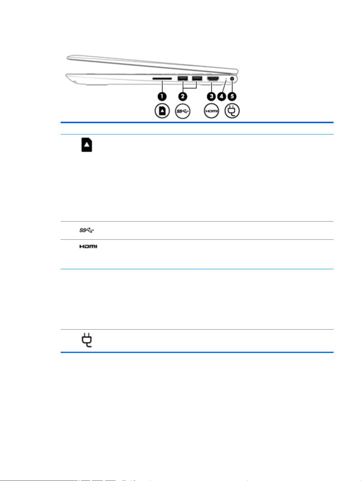
Right side
Component Description
(1) Memory card reader Reads optional memory cards that enable you to store, manage,
share, or access information.
To insert a card:
1. Hold the card label-side up, with connectors facing the
computer.
2. Insert the card into the memory card reader, and then
press in on the card until it is rmly seated.
To remove a card:
▲
Press in on the card, and then remove it from the memory
card reader.
(2) USB 3.0 ports (2) Connect optional USB devices, such as a keyboard, mouse,
external drive, printer, scanner or USB hub.
(3) HDMI port Connects an optional video or audio device, such as a high-
denition television, any compatible digital or audio component,
or a high-speed High-Denition Multimedia Interface (HDMI)
device.
(4) AC adapter and battery light
(5) Power connector Connects an AC adapter.
●
White: The AC adapter is connected and the battery is fully
charged.
●
Blinking white: The AC adapter is disconnected and the
battery has reached a low battery level.
●
Amber: The AC adapter is connected and the battery is
charging.
●
O: The battery is not charging.
Right side 7
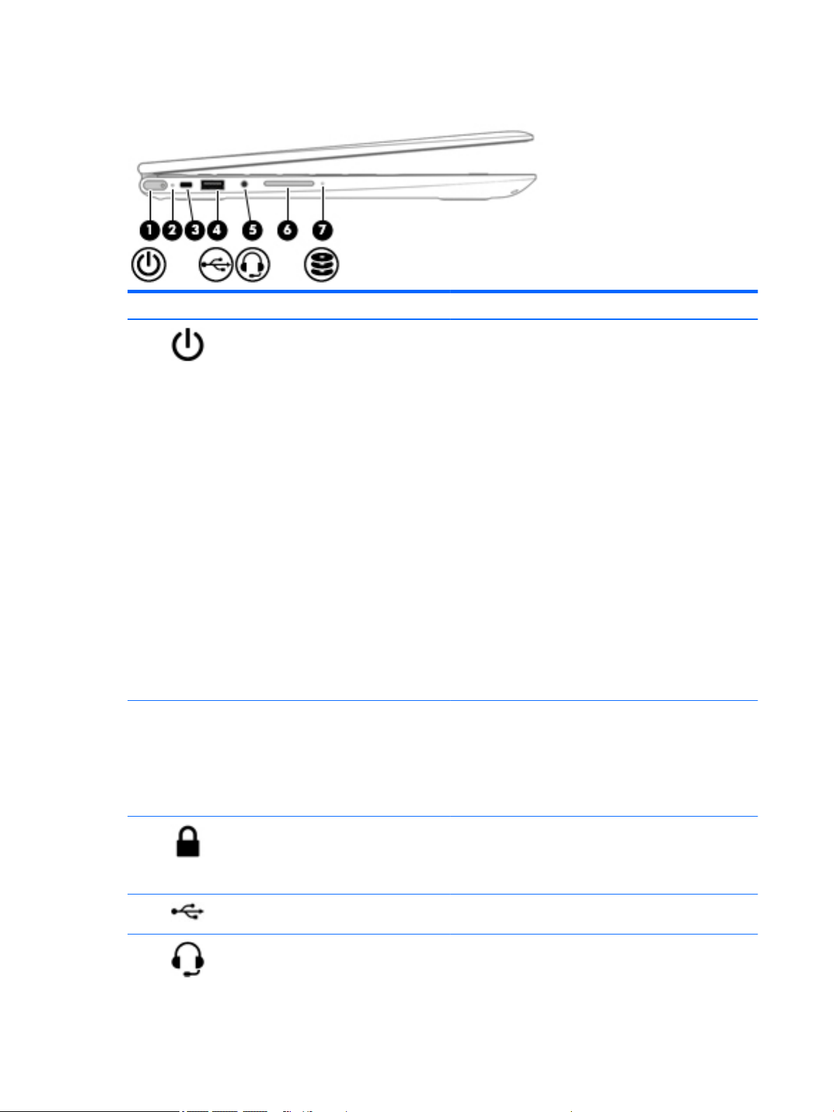
Left side
Component Description
(1) Power button
(2) Power light
●
When the computer is o, press the button to turn on the
computer.
●
When the computer is on, press the button briey to
initiate Sleep.
●
When the computer is in the Sleep state, press the button
briey to exit Sleep.
●
When the computer is in Hibernation, press the button
briey to exit Hibernation.
CAUTION: Pressing and holding down the power button results
in the loss of unsaved information.
If the computer has stopped responding and shutdown
procedures are ineective, press and hold the power button
down for at least 5 seconds to turn o the computer.
To learn more about your power settings, see your power
options.
▲
Type power in the taskbar search box, and then select
Power and sleep settings.
‒ or -
Right-click the Start button, and then select Power
Options.
●
On: The computer is on.
●
Blinking: The computer is in the Sleep state, a powersaving state. The computer shuts o power to the display
and other unneeded components.
●
O: The computer is o or in Hibernation. Hibernation is a
power-saving state that uses the least amount of power.
(3) Security cable slot Attaches an optional security cable to the computer.
(4) USB 2.0 port Connects an optional USB device, such as a keyboard, mouse,
(5) Audio-out (headphone)/Audio-in (microphone)
combo jack
8 Chapter 2 External component identication
NOTE: The security cable is designed to act as a deterrent, but
it may not prevent the computer from being mishandled or
stolen.
external drive, printer, scanner, or USB hub.
Connects optional powered stereo speakers, headphones,
earbuds, a headset, or a television audio cable. Also connects an
optional headset microphone. This jack does not support
optional standalone microphones.

Component Description
WARNING! To reduce the risk of personal injury, adjust the
volume before putting on headphones, earbuds, or a headset.
For additional safety information, refer to the Regulatory,
Safety, and Environmental Notices.
To access this guide:
▲
Select the Start button, select All apps, select HP Help and
Support, and then select HP Documentation.
NOTE: When a device is connected to the jack, the computer
speakers are disabled.
(6) Volume button Control speaker volume on the computer.
1. To increase speaker volume, press the back edge of the
button.
2. To decrease speaker volume, press the front edge of the
button.
(7) Drive light
●
Blinking white: The hard drive is being accessed.
●
Amber: HP 3D DriveGuard has temporarily parked the hard
drive.
NOTE: On select products, the drive light will always remain
o.
Left side 9
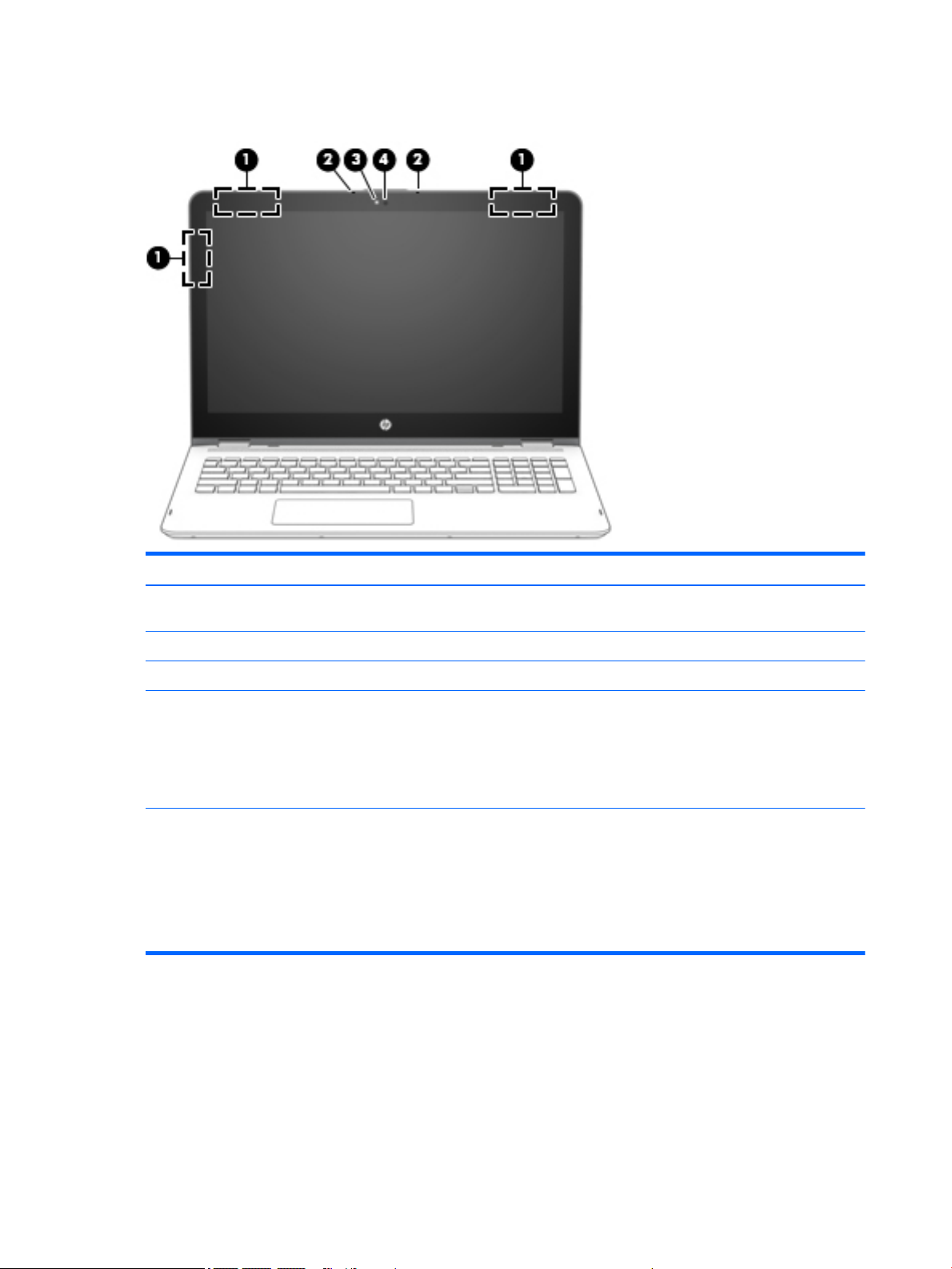
Display
Component Description
(1) WLAN antennas* Send and receive wireless signals to communicate with wireless local
area networks (WLANs).
(2) Internal microphones Record sound.
(3) Webcam light On: The webcam is in use.
(4) Webcam Records video and captures photographs. Some products allow you
*The antennas are not visible from the outside of the computer, and the antenna location may vary.For optimal transmission, keep the
areas immediately around the antennas free from obstructions.
For wireless regulatory notices, see the section of the Regulatory, Safety, and Environmental Notices that applies to your country or
region.
To access this guide:
▲
Select the Start button, select All apps, select HP Help and Support, and then select HP Documentation.
to video conference and chat online using streaming video.
To use a webcam (integrated camera):
▲
Type camera in the taskbar search box, and then select
Camera.
10 Chapter 2 External component identication
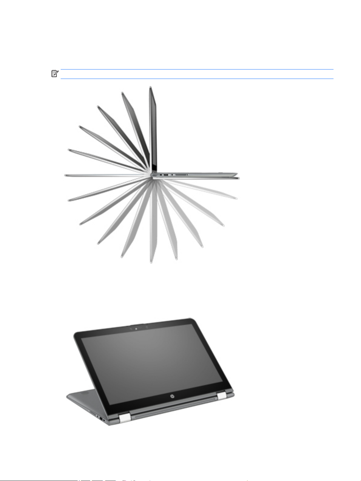
Changing your notebook position (select products only)
Your computer can function as a classic notebook, and in addition, the display can be rotated so that the
computer transforms into an entertainment stand, an interactive stand, or a tablet.
NOTE: The TouchPad and keyboard functions are locked during the entertainment and tablet modes.
Changing your notebook to an entertainment stand (select products only)
To change your notebook to an entertainment stand, raise the display, and then rotate the display backward
to a stand position (about 315 degrees).
Display 11
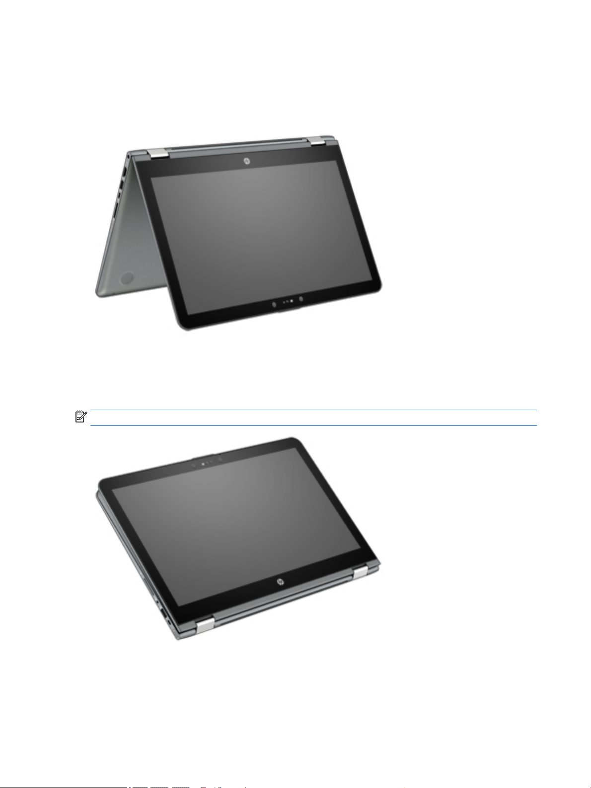
Changing your notebook to an interactive stand (select products only)
To change your notebook to an interactive stand, raise the display, and then rotate the display backward to a
stand position (about 315 degrees). Position the notebook on its edges.
Changing your notebook to a tablet (select products only)
To change your notebook to a tablet, raise the display, and then rotate the display backward until it is ush
with the computer bottom (360 degrees).
NOTE: When the computer is in tablet mode, you can use the on-screen keyboard.
12 Chapter 2 External component identication
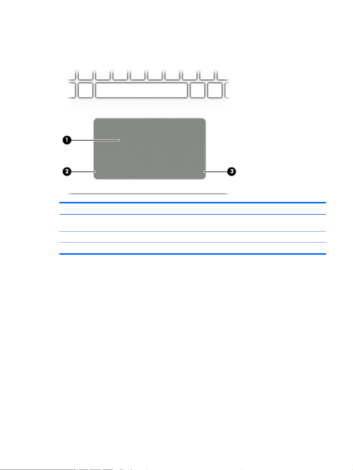
Top
TouchPad
Component Description
(1) TouchPad zone Reads your nger gestures to move the pointer or activate items
on the screen.
(2) Left TouchPad button Functions like the left button on an external mouse.
(3) Right TouchPad button Functions like the right button on an external mouse.
Top 13
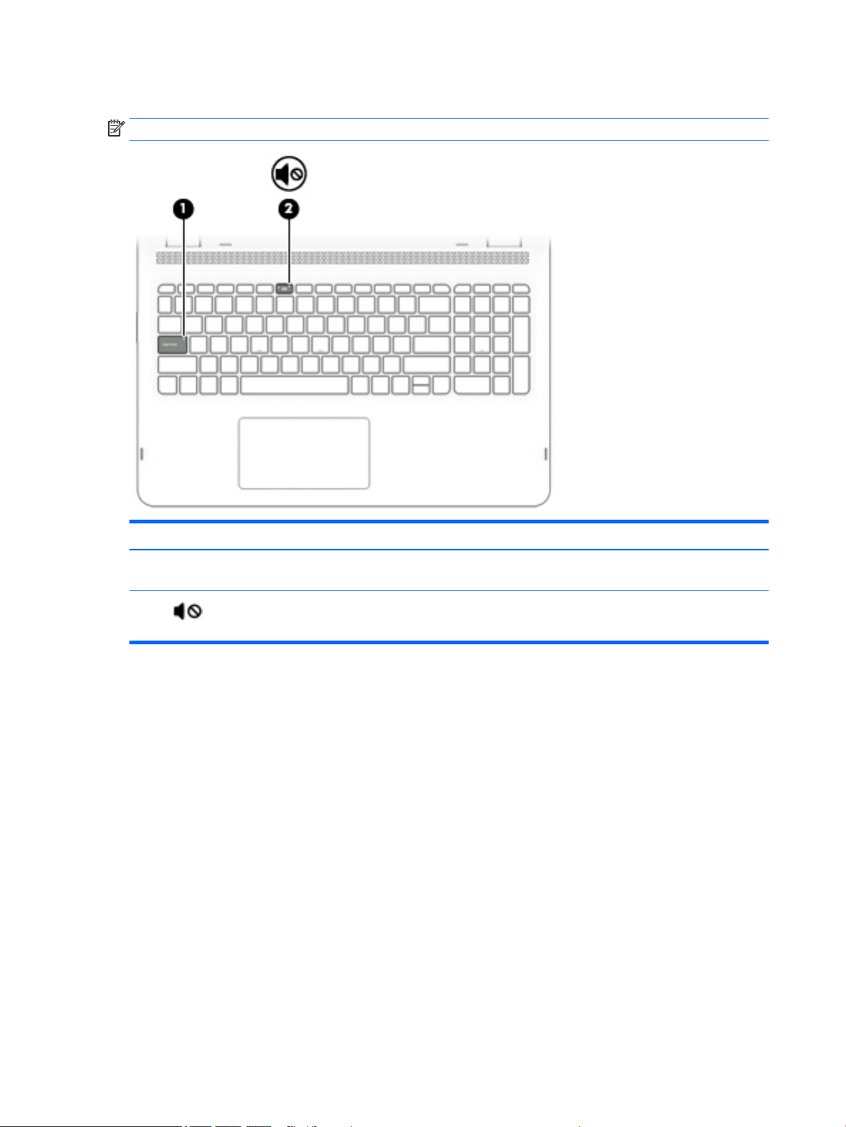
Lights
NOTE: Your computer may look slightly dierent from the illustration below.
Component Description
(1) Caps lock light On: Caps lock is on, which switches the key input to all capital
letters.
(2) Mute light
●
Amber: Computer sound is o.
●
O: Computer sound is on.
14 Chapter 2 External component identication
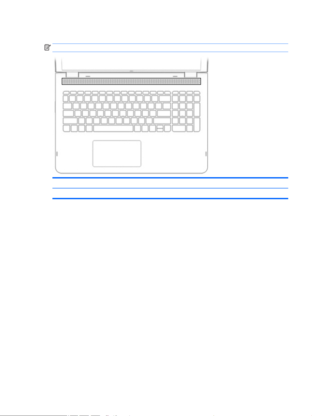
Speakers
NOTE: Your computer may look slightly dierent from the illustration below.
Component Description
Speakers Produce sound.
Top 15

Keys
NOTE: Your computer may look slightly dierent from the illustration below.
Component Description
(1) esc key Displays system information when pressed in combination with
the fn key.
(2) fn key Displays system information when pressed in combination with
the esc key.
(3) Windows key Opens the Start menu.
NOTE: Pressing the Windows key again will close the Start
menu.
(4) Action keys Execute frequently used system functions.
NOTE: On select products, the f5 action key turns the keyboard
backlight feature o or on.
(5) num lock key (select products only) Alternates between the navigational and numeric functions on
the integrated numeric keypad.
(6) Integrated numeric keypad (select products
only)
When num lock is on, the keypad can be used like an external
numeric keypad.
16 Chapter 2 External component identication
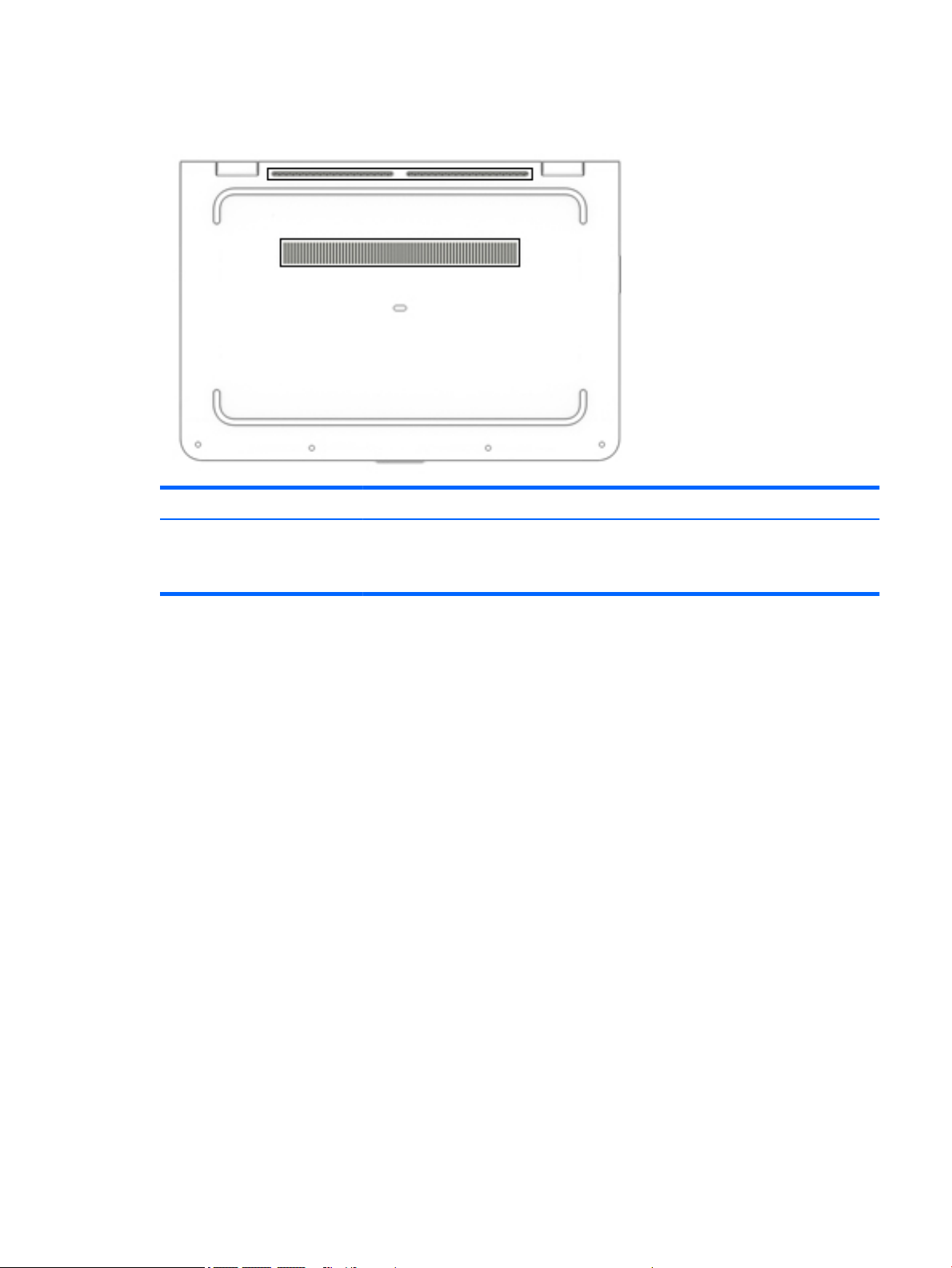
Bottom
Component Description
Vents (3) Enable airow to cool internal components.
NOTE: The computer fan starts up automatically to cool internal components and prevent
overheating. It is normal for the internal fan to cycle on and o during routine operation.
Bottom 17

3 Illustrated parts catalog
NOTE: HP continually improves and changes product parts. For complete and current information on
supported parts for your slate, go to http://partsurfer.hp.com, select your country or region, and then follow
the on-screen instructions.
Locating the serial number, model number, product number, and warranty information
The labels axed to the computer provide information you may need when you troubleshoot system
problems or travel internationally with the computer.
IMPORTANT: The labels described in this location are located on the bottom of the computer.
●
Service label—Provides important information to identify your computer. When contacting support, you
will probably be asked for the serial number, and possibly for the product number or the model number.
Locate these numbers before you contact support.
Your service label will resemble one of the examples shown below. Refer to the illustration that most
closely matches the service label on your computer.
Component
(1) Serial number
(2) Product number
(3) Warranty period
(4) Model number (select products only)
18 Chapter 3 Illustrated parts catalog

Component
(1) Model name (select products only)
(2) Product number
(3) Serial number
(4) Warranty period
●
Regulatory label(s)—Provide(s) regulatory information about the computer.
●
Wireless certication label(s)—Provide(s) information about optional wireless devices and the approval
markings for the countries or regions in which the devices have been approved for use.
Locating the serial number, model number, product number, and warranty information 19
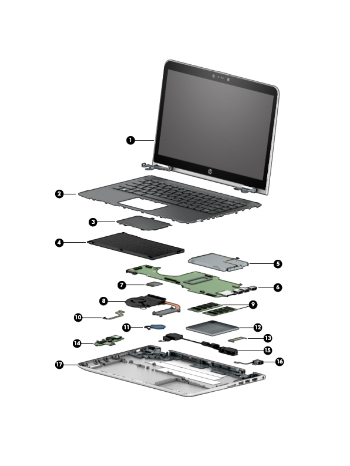
Computer major components
20 Chapter 3 Illustrated parts catalog

Item Component Spare part number
(1) Display assembly: The display assembly is spared at the subcomponent level only. For more display assembly spare part
information, see Display assembly subcomponents on page 27.
(2) Keyboard/top cover (includes keyboard cable):
In modern gold nish (for use on all computer models):
For use in Belgium 856038-A41
For use in Bulgaria 856038-261
For use in Canada 856038-DB1
For use in the Czech Republic and Slovakia 856038-FL1
For use in Denmark, Finland, and Norway 856038-DH1
For use in France 856038-051
For use in Germany 856038-041
For use in Greece 856038-151
For use in Hungary 856038-211
For use in Israel 856038-BB1
For use in Italy 856038-061
For use in Latin America 856038-161
For use in the Netherlands 856038-B31
For use in Portugal 856038-131
For use in Romania 856038-271
For use in Russia 856038-251
For use in Saudi Arabia 856038-171
For use in Slovenia 856038-BA1
For use in Spain 856038-071
For use in Switzerland 856038-BG1
For use in Thailand 856038-281
For use in Turkey 856038-141
For use in the United Kingdom 856038-031
For use in the United States 856038-001
In natural silver nish (for use on all computer models):
For use in Belgium 856037-A41
For use in Bulgaria 856037-261
For use in Canada 856037-DB1
For use in the Czech Republic and Slovakia 856037-FL1
For use in Denmark, Finland, and Norway 856037-DH1
Computer major components 21
 Loading...