

Page 1

HP Pavilion x360 15 Convertible PC
Maintenance and Service Guide
IMPORTANT! This document is intended for
HP authorized service providers only.
Page 2

© Copyright 2017 Hewlett-Packard
Development Company, L.P.
Bluetooth is a trademark owned by its
proprietor and used by HP Inc. under license.
Intel, Core, and Pentium are U.S. registered
trademarks of Intel Corporation. Microsoft and
Windows are either registered trademarks or
trademarks of Microsoft Corporation in the
United States and/or other countries. SD Logo
is a trademark of its proprietor.
The information contained herein is subject to
change without notice. The only warranties for
HP products and services are set forth in the
express warranty statements accompanying
such products and services. Nothing herein
should be construed as constituting an
additional warranty. HP shall not be liable for
technical or editorial errors or omissions
contained herein.
Second Edition: August 2017
First Edition: April 2017
Document Part Number: 926167-002
Product notice
This guide describes features that are common
to most models. Some features may not be
available on your computer.
Not all features are available in all editions of
Windows 10. This computer may require
upgraded and/or separately purchased
hardware, drivers and/or software to take full
advantage of Windows 10 functionality. See for
http://www.microsoft.com details.
Page 3

Safety warning notice
WARNING! To reduce the possibility of heat-related injuries or of overheating the device, do not place
the device directly on your lap or obstruct the device air vents. Use the device only on a hard, at surface. Do
not allow another hard surface, such as an adjoining optional printer, or a soft surface, such as pillows or rugs
or clothing, to block airow. Also, do not allow the AC adapter to contact the skin or a soft surface, such as
pillows or rugs or clothing, during operation. The device and the AC adapter comply with the user-accessible
surface temperature limits dened by the International Standard for Safety of Information Technology
Equipment (IEC 60950-1).
iii
Page 4

iv Safety warning notice
Page 5

Table of contents
1 Product description ....................................................................................................................................... 1
2 External component identication .................................................................................................................. 4
Display .................................................................................................................................................................... 4
Speakers ................................................................................................................................................................. 5
TouchPad ................................................................................................................................................................ 5
Left side ................................................................................................................................................................. 6
Right side ............................................................................................................................................................... 7
Bottom ................................................................................................................................................................... 8
3 Illustrated parts catalog ................................................................................................................................ 9
Labels ..................................................................................................................................................................... 9
Computer major components .............................................................................................................................. 10
Display assembly subcomponents ...................................................................................................................... 16
Miscellaneous parts ............................................................................................................................................. 18
4 Removal and replacement preliminary requirements ..................................................................................... 19
Tools required ...................................................................................................................................................... 19
Service considerations ......................................................................................................................................... 19
Plastic parts ....................................................................................................................................... 19
Cables and connectors ...................................................................................................................... 19
Drive handling ................................................................................................................................... 20
Grounding guidelines ........................................................................................................................................... 21
Electrostatic discharge damage ........................................................................................................ 21
Packaging and transporting guidelines .......................................................................... 22
Workstation guidelines ................................................................................ 22
5 Removal and replacement procedures ........................................................................................................... 24
Component replacement procedures .................................................................................................................. 24
Keyboard/top cover ........................................................................................................................... 24
TouchPad cable .................................................................................................................................. 28
TouchPad ........................................................................................................................................... 29
Battery ............................................................................................................................................... 30
Hard drive .......................................................................................................................................... 31
Audio jack board cable ...................................................................................................................... 33
Audio jack board ................................................................................................................................ 34
v
Page 6

Power button board cable ................................................................................................................. 35
Power button board .......................................................................................................................... 36
Speakers ............................................................................................................................................ 37
System board .................................................................................................................................... 38
WLAN module .................................................................................................................................... 42
Fan/heat sink assembly .................................................................................................................... 43
Memory module ................................................................................................................................ 45
Power connector cable ...................................................................................................................... 47
Display assembly ............................................................................................................................... 48
6 Computer Setup (BIOS), TPM, and HP Sure Start ............................................................................................. 58
Using Computer Setup ......................................................................................................................................... 58
Starting Computer Setup .................................................................................................................. 58
Navigating and selecting in Computer Setup ................................................................................... 58
Restoring factory settings in Computer Setup ................................................................................. 59
Updating the BIOS ............................................................................................................................. 60
Determining the BIOS version ......................................................................................... 60
Downloading a BIOS update ........................................................................................... 60
Changing the boot order using the f9 prompt .................................................................................. 61
TPM BIOS settings (select products only) ........................................................................................................... 62
Using HP Sure Start (select products only) ......................................................................................................... 62
7 HP PC Hardware Diagnostics (UEFI) ............................................................................................................... 63
Downloading HP PC Hardware Diagnostics (UEFI) to a USB device .................................................................... 64
8 Specications .............................................................................................................................................. 65
9 Power cord set requirements ........................................................................................................................ 66
Requirements for all countries ............................................................................................................................ 66
Requirements for specic countries and regions ................................................................................................ 66
10 Recycling .................................................................................................................................................. 68
Index ............................................................................................................................................................. 69
vi
Page 7

1 Product description
Category Description
Product Name HP Pavilion x360 15 Convertible PC (model number 15-br1xx)
HP Pavilion x360 15 Convertible PC (model number 15-br0xx)
Processors For use only on computer models with model number 15-br1xx:
●
Intel® Core™ i7-8550U 1.80-GHz (SC turbo up to 4.00-GHz) quad core processor (8.0-GB L3 cache, 2400MHz FSB, 15-W)
For use on all computer models:
●
Intel Core i7-7500U 2.70-GHz (SC turbo up to 3.56-GHz) dual core processor (4.0-GB L3 cache, 2133MHz FSB, 15-W)
●
Intel Core i5-7200U 2.56-GHz (SC turbo up to 3.10-GHz) dual core processor (3.0-GB L3 cache, 2133MHz FSB, 15-W)
●
Intel Core i3-7100U 2.40-GHz dual core processor (3.0-GB L3 cache, 2133-MHz FSB, 15-W)
●
Intel Pentium™ 4415U 2.36-GHz dual core processor (2.0-GB L3 cache, 2133-MHz FSB, 15-W)
Chipset Integrated with soldered-on-circuit (SoC)
Graphics Switchable discrete graphics:
AMD Radeon® 530 R17M-M1-70 (Meso Pro) with up to 4096-MB of discrete video memory (512-MB×16
DDR3×4 pieces; available only on computer models equipped with an Intel Core i7-7500U processor)
AMD Radeon 530 R17M-M1-70 (Meso Pro) with up to 2048-MB of discrete video memory (256-MB×16
DDR3×4 pieces; available only on computer models equipped with an Intel Core i5-7200U processor or an
Intel Core i3-7100U processor)
Internal graphics:
Intel HD Graphics 620 (available only on computer models equipped with an Intel Core i5 processor or an Intel
Core i3 processor)
Intel HD Graphics (available only on computer models equipped with an Intel Pentium 4415U processor)
Support for HD decode, DX12, and high-denition multimedia interface (HDMI)
Panel 15.6-in, full high-denition (FHD), white light-emitting (WLED), BrightView (1920×1080), slim/at (3.2-mm),
UWVA, eDP, 220 nits, 16:9 ultra wide aspect ratio TouchScreen display assembly
15.6-in, high-denition (HD), WLED, AntiGlare (1366×768), slim/at (3.2-mm), SVA, eDP, 220 nits, 16:9 ultra
wide aspect ratio TouchScreen display assembly
Support for active stylus
Memory Two SODIMM memory module slots, non-customer-accessible/non-upgradable
Supports up to 16-GB of system memory
DDR4-2133 dual channel support (DDR4-2400 downgrade to DDR4-2133)
Supports the following congurations:
●
16384 MB (8192 MB × 2)
●
8192 MB (8192 MB × 1)
●
6144 MB (4096 MB + 2048 MB)
1
Page 8

Category Description
Memory (continued)
Storage Single hard drive congurations:
●
4096 MB (4096 MB × 1)
1-TB, 5400-rpm, 7.2-mm hard drive
500-GB, 5400-rpm, 7.0-mm hard drive
Solid-state hard drive congurations:
1-TB, 5400-rpm, 7.2-mm solid-state hard drive with 8-GB NAND
500-GB, 5400-rpm, 7.0-mm solid-state hard drive with 8-GB NAND
Solid-state drive:
Support for M.2 SATA solid-state drive (support for storage function, port 1; not available on computer
models equipped with an Intel Pentium processor)
Support for Serial Advanced Technology Attachment (SATA)
Support for hard drive and solid-state drive
For use only on computer models with model number 15-cc7xx:
●
512-GB, 2280, Peripheral Component Interconnect Express (PCIe), Non-Volatile Memory Express (NVMe)
solid-state drive
●
256-GB, 2280, PCIe, NVMe solid-state drive
For use on all computer models:
M.2 SATA-3 solid-state drive with Triple-Level Cell (TLC):
●
512-GB
●
256-GB
●
128-GB
M.2 SATA-3 solid-state drive: 256-GB and 128-GB
Dual storage congurations (not available on computer models equipped with an Intel Pentium processor):
1-TB, 5400-rpm, 7.2-mm hard drive with 128-GB M.2 SATA-3 solid-state drive
500-GB, 5400-rpm, 7.0-mm hard drive with 128-GB M.2 SATA-3 solid-state drive
Optical drive HP external DVD±RW DL SuperMulti Drive
Audio and video Support for the following cameras:
2 Chapter 1 Product description
HP Wide Vision FHD infrared camera with indicator light and 2 infrared lights, USB 2.0, FHD hybrid BSI sensor,
f2.2, WDR, 88° wide eld of vision, 1080p by 30 frames per second (available only on computer models
equipped with an FHD display assembly, an Intel I7 processor and a graphics subsystem with discrete video
memory and computer models equipped with an FHD display assembly and an Intel Pentium processor)
HP Wide Vision HD camera with indicator light, USB 2.0, HD BSI sensor, f2.0, WDR, 88° wide eld of vision,
720p by 30 frames per second
Support for B&O Play
Support for B&O Play Audio Control
Support for dual-array digital microphones with appropriate beam-forming, echo-cancellation, noisesuppression software
Support for dual speakers
Support for HP Audio Boost
Page 9

Category Description
Audio and video
(continued)
Sensors
Wireless WLAN:
External media cards Micro-Secure Digital (SD®) media reader slot
Ports
Support for Windows Hello
●
Accelerometer (ST Micro HP2DC)
●
Gyroscope/E-compass/Accelerometer (ST Micro HP9DS1)
●
Integrated sensor hub
Integrated wireless local area network (WLAN) options by way of wireless module
Two M.2/PCIe WLAN antennas built into display assembly
Integrated wireless personal area network (PAN) supported by Bluetooth® 4.2 combo card
Support for the Intel Dual Band Wireless-AC 7265 802.11 AC 2×2 WiFi + Bluetooth 4.2 Combo Adapter (nonvPro) and Intel Dual Band Wireless-AC 3168 802.11AC 1×1 WiFi + Bluetooth 4.2 Combo Adapter (nonvPro) formats
●
AC Smart Pin adapter plug
●
Audio-out (headphone)/audio-in (microphone) combo jack
●
HDMI v1.4 supporting up to 1920×1080 @ 60Hz
●
USB 3.x ports (2)
●
USB Type-C port
Keyboard/pointing
devices
Power requirements Support for a 3-cell, 48-WHr, 4.2-AHr, Li-ion battery
Security Security cable lock slot
Operating system Preinstalled: Windows 10 and Windows 10 Professional
Full-sized, three-coat, backlt, island-style keyboard with numeric keypad
TouchPad requirements:
●
ClickPad with image sensor
●
MultiTouch gestures enabled
●
Support for Modern TrackPad gestures
●
Taps enabled as default
Support for the following AC adapters:
●
90-W AC adapter (PFC, S-3P, 4.5-mm)
●
65-W HP Smart AC adapter (non-PFC, EM, RC, 4.5-mm)
●
65-W AC adapter (non-PFC, S-3P, 4.5-mm)
●
45-W HP Smart AC adapter (non-PFC, RC, 4.5-mm, non-slim)
Support for a 1.00-m power cord with a C5 connector in 12 countries/regions.
Support for Trusted Platform Module (fTPM) 2.0 (rmware-based)
For developed market (ML): Windows 10 Home ML and Windows 10 Home Plus ML
For emerging market (EM/SL): Windows 10 Home EM/SL and Windows 10 Home Plus EM/SL
Serviceability End user replaceable part: AC adapter
3
Page 10
2 External component identication
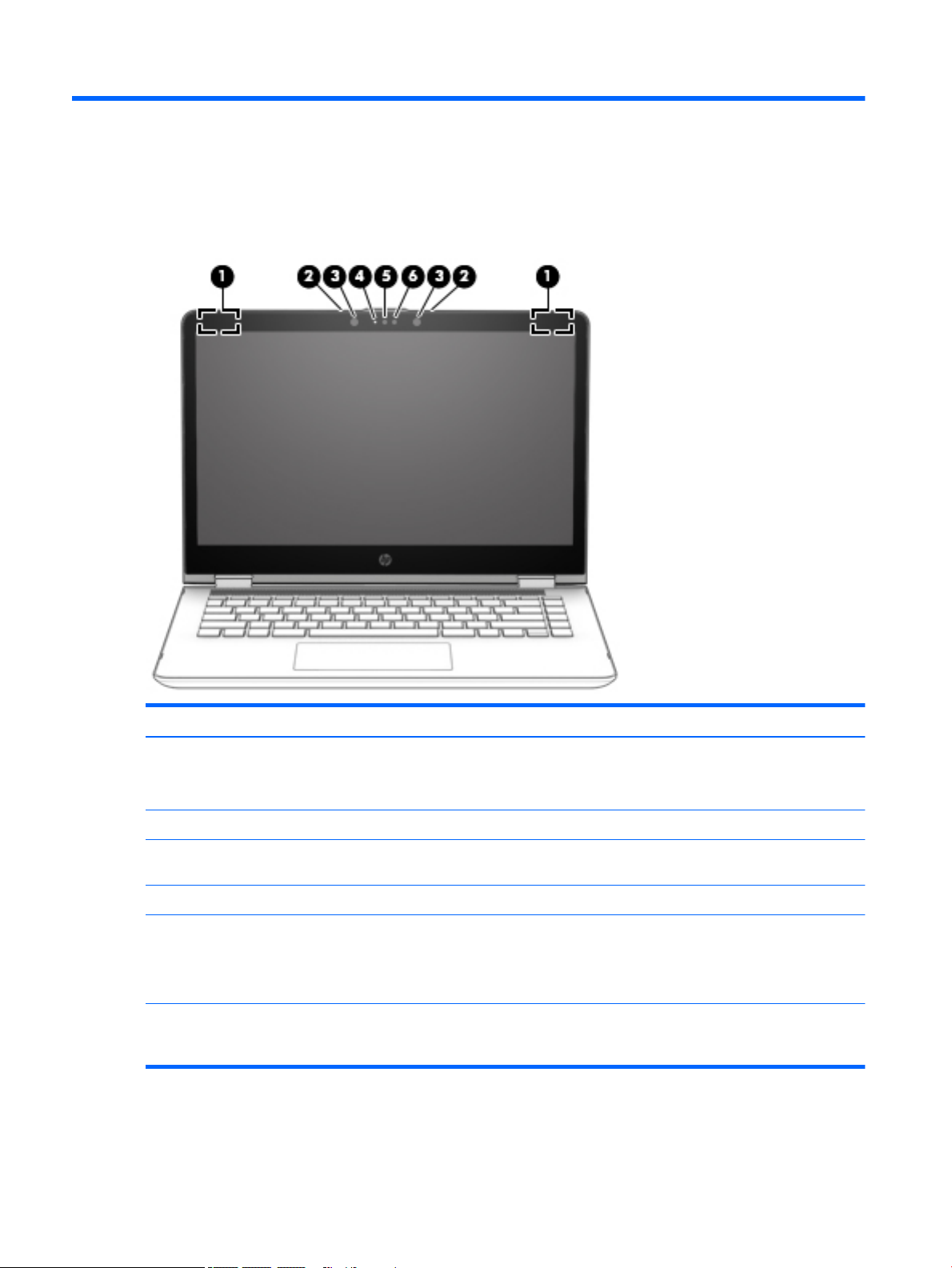
Display
Item Component Description
(1) WLAN antennas (2)* Send and receive wireless signals to communicate with WLANs.
NOTE: The position of the WLAN antennas may dier, depending
on model.
(2) Internal microphone Records sound.
(3) Webcam Records video, captures still photographs, and allows video
conferences and online chat by means of streaming video.
(4) Webcam light On: The webcam is in use.
(5) Internal display switch Turns o the display or initiates Sleep if the display is closed while
the power is on.
NOTE: The display switch is not visible from the outside of
the computer.
*The antennas, IR emitters (select models only), and sensors are not visible from the outside of the computer. For optimal
transmission, keep the areas immediately around the antennas, IR emitters, and sensors free from obstructions. For wireless
regulatory notices, see the section of the Regulatory, Safety, and Environmental Notices that applies to your country or region.
4 Chapter 2 External component identication
Page 11
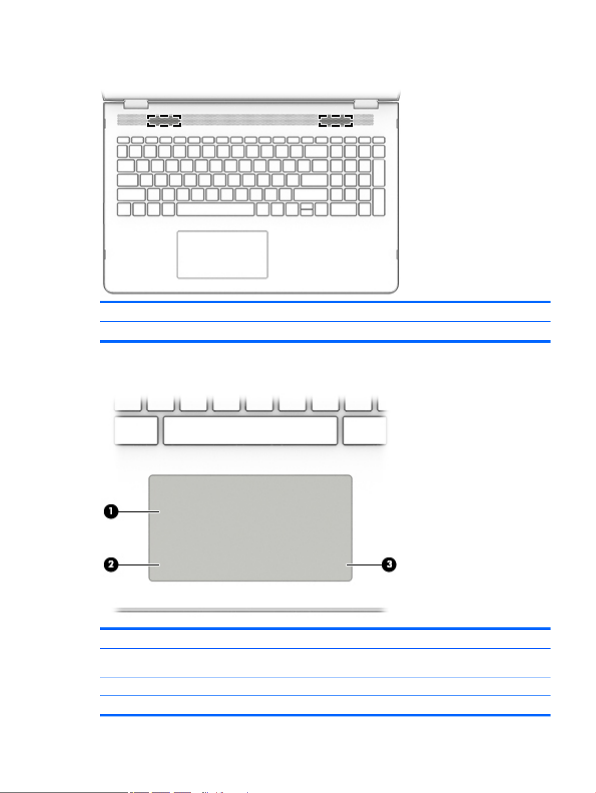
Speakers
Item Component Description
(1) Speakers Produce sound.
TouchPad
Item Component Description
(1) TouchPad zone Moves the on-screen pointer and selects or activates items on
the screen.
(2) Left control zone Textured area that allows you to perform additional gestures.
(3) Right control zone Textured area that allows you to perform additional gestures.
Speakers 5
Page 12
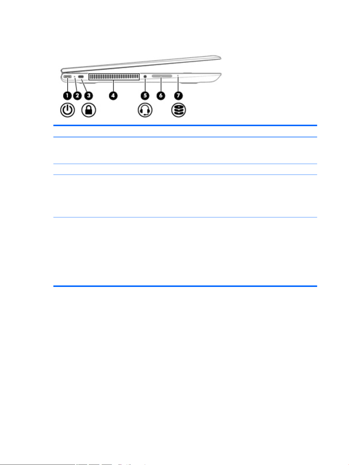
Left side
Item Component Description
(1) Security cable slot Attaches an optional security cable to the computer.
(2) Power connector Connects an AC adapter.
NOTE: The security cable is designed to act as a deterrent, but it
may not prevent the computer from being mishandled or stolen.
(3) AC adapter light
(4) Memory card reader Reads optional memory cards that store, manage, share, or access
●
White: The AC adapter is connected and the battery is
charged.
●
Amber: The AC adapter is connected and the battery is
charging.
●
O: The computer is using battery power.
information.
To insert a card:
▲
Hold the card label-side up, with connectors facing the slot,
insert the card into the slot, and then push in on the card
until it is rmly seated.
To remove a card:
▲
Press in on the card it until it pops out.
6 Chapter 2 External component identication
Page 13
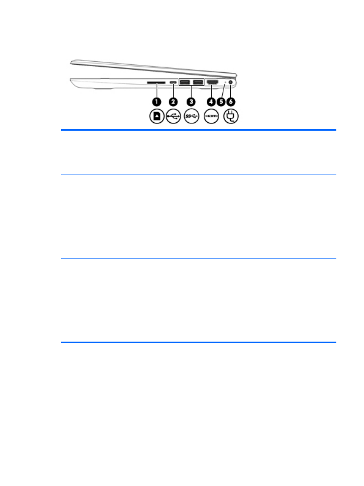
Right side
Item Component Description
(1) Power light
(2) Audio-out (headphone)/Audio-in (microphone)
jack
(3) USB 2.0 port Connect optional USB devices, such as a keyboard, mouse,
(4) USB 3.0 charging (powered) port Connects an optional USB device, such as a keyboard, mouse,
(5) HDMI port Connects an optional video or audio device, such as a high-
●
White: Computer is on.
●
Blinking white: Computer is in Sleep mode.
●
O: The computer is o.
Connects optional powered stereo speakers, headphones,
earbuds, a headset, or a television audio cable. Also connects an
optional headset microphone. This jack does not support optional
microphone-only devices.
WARNING! To reduce the risk of personal injury, adjust
the volume before putting on headphones, earbuds, or a headset.
NOTE: When a device is connected to the jack, the computer
speakers are disabled.
NOTE: Be sure that the device cable has 4-conductor connector
that supports both audio-out (headphone) and audio-in
(microphone).
external drive, printer, scanner or USB hub.
external drive, printer, scanner or USB hub. Standard USB ports
will not charge all USB devices or will charge using a low current.
Some USB devices require power and require you to use a powered
port.
denition television, any compatible digital or audio component,
or a high-speed High-Denition Multimedia Interface (HDMI)
device.
Right side 7
Page 14
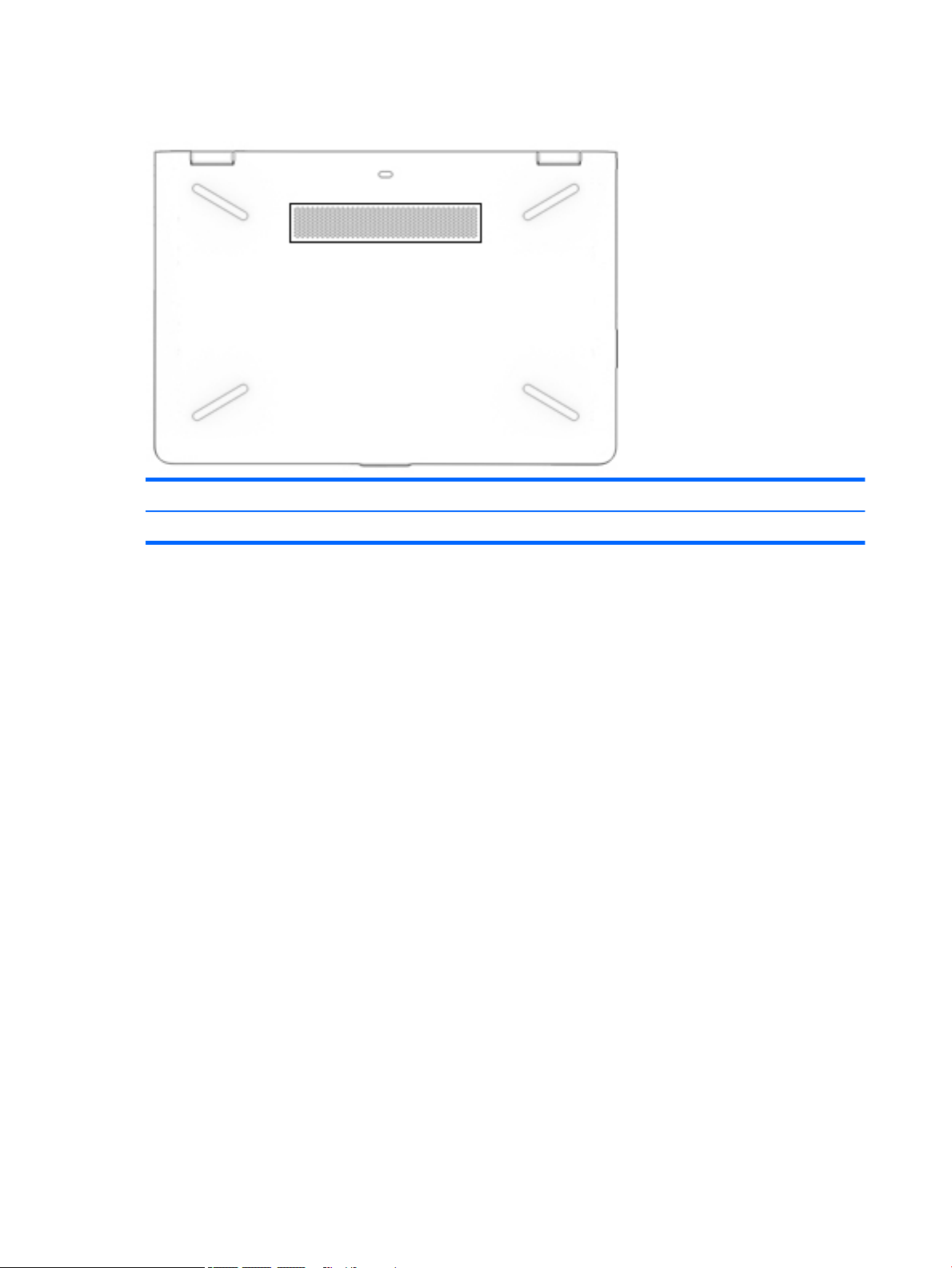
Bottom
Item Component Description
(1) Speakers (2) Produce sound.
8 Chapter 2 External component identication
Page 15
3 Illustrated parts catalog
NOTE: HP continually improves and changes product parts. For complete and current information on
supported parts for your computer, go to http://partsurfer.hp.com, select your country or region, and then
follow the on-screen instructions.
Labels
The labels axed to the computer provide information that may be needed when troubleshooting system
problems or travelling internationally with the computer.
IMPORTANT: Check the following locations for the labels described in this section: the bottom of the
computer, inside the battery bay, under the service door, on the back of the display, or on the bottom of a
tablet kickstand.
●
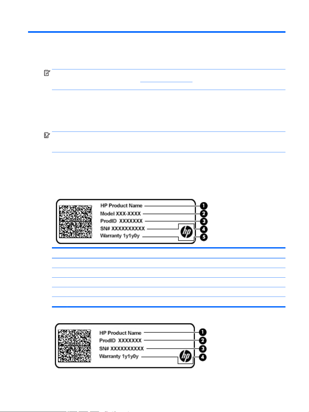
Service label—Provides important information to identify your computer. When contacting support, you
may be asked for the serial number, the product number, or the model number. Locate this information
before you contact support.
Your service label will resemble one of the examples shown below. Refer to the illustration that most
closely matches the service label on your computer.
Component
(1) HP product name (select products only)
(2) Model number
(3) Product number
(4) Serial number
(5) Warranty period
Labels 9
Page 16
Component
(1) HP product name (select products only)
(2) Product number
(3) Serial number
(4) Warranty period
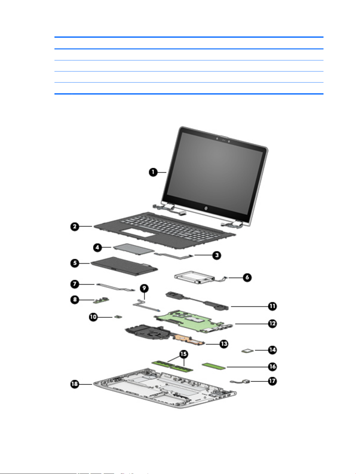
Computer major components
10 Chapter 3 Illustrated parts catalog
Page 17

Item Component Spare part number
(1) Display assembly: The display assembly is spared at the subcomponent level only. For more display assembly spare part
information, see Display assembly subcomponents on page 16.
(2) Keyboard/top cover
In ash silver nish with backlight for use only on computer models equipped with a graphics subsystem with
discrete memory (includes backlight cable and keyboard cable):
For use in Canada 924525-DB1
For use in the United States 924525-001
In ash silver nish with backlight for use only on computer models equipped with a graphics subsystem with UMA memory
(includes backlight cable and keyboard cable):
For use in Canada 924524-DB1
For use in the United States 924524-001
Keyboard/top cover
In ash silver nish for use only on computer models equipped with a graphics subsystem with discrete memory
(includes keyboard cable):
For use in Belgium 924523-A41
For use in Bulgaria 924523-261
For use in Canada 924523-DB1
For use in the Czech Republic and Slovakia 924523-FL1
For use in Denmark, Finland, and Norway 924523-DH1
For use in France 924523-051
For use in Germany 924523-041
For use in Greece 924523-151
For use in Hungary 924523-211
For use in India 924523-002
For use in Israel 924523-BB1
For use in Italy 924523-061
For use in Latin America 924523-161
For use in the Netherlands 924523-B31
For use in Portugal 924523-131
For use in Romania 924523-271
For use in Russia 924523-251
For use in Saudi Arabia 924523-171
For use in Slovenia 924523-BA1
For use in Spain 924523-071
For use in Switzerland 924523-BG1
For use in Turkey 924523-141
Computer major components 11
Page 18

Item Component Spare part number
For use in the United Kingdom 924523-031
For use in the United States 924523-001
Keyboard/top cover
In ash silver nish for use only on computer models equipped with a graphics subsystem with UMA memory
(includes keyboard cable):
For use in Belgium 924522-A41
For use in Bulgaria 924522-261
For use in Canada 924522-DB1
For use in the Czech Republic and Slovakia 924522-FL1
For use in Denmark, Finland, and Norway 924522-DH1
For use in France 924522-051
For use in Germany 924522-041
For use in Greece 924522-151
For use in Hungary 924522-211
For use in India 924522-002
For use in Israel 924522-BB1
For use in Italy 924522-061
For use in Latin America 924522-161
For use in the Netherlands 924522-B31
For use in Portugal 924522-131
For use in Romania 924522-271
For use in Russia 924522-251
For use in Saudi Arabia 924522-171
For use in Slovenia 924522-BA1
For use in Spain 924522-071
For use in Switzerland 924522-BG1
For use in Turkey 924522-141
For use in the United Kingdom 924522-031
For use in the United States 924522-001
(3) TouchPad cable (includes double-sided adhesive) 924509-001
(4) TouchPad (does not include TouchPad bracket or TouchPad cable) 924529-001
NOTE: The TouchPad bracket is available using spare part number 924517-001. The TouchPad cable is available using
spare part number 924509-001.
TouchPad bracket (not illustrated) 924517-001
(5) Battery (3-cell, 48-WHr, 4.2-AHr, Li-ion) 916812-855
12 Chapter 3 Illustrated parts catalog
Page 19

Item Component Spare part number
(6) Hard drive (does not include hard drive rubber sleeve):
1-TB, 5400-rpm, SATA, 8-GB hybrid hard drive 924036-856
1-TB, 5400-rpm, SATA hard drive 762888-859
500-GB, 5400-rpm, SATA, 8-GB hybrid hard drive 731863-858
500-GB, 5400-rpm, SATA hard drive 683839-859
NOTE: The hard drive rubber sleeve is available using spare part number 924515-001.
Hard drive counterbalance weight (not illustrated) 934083-001
(7) Audio jack board cable (includes double-sided adhesive) 924510-001
(8) Audio jack board (includes audio jack, volume control actuators, and hard drive activity
light; does not include audio jack board cable)
(9) Power button board cable (includes double-sided adhesive) 924511-001
(10) Power button board (does not include power button board cable) 924526-001
(11) Speakers (include cables and 4 rubber isolators) 924538-001
(12) System board (includes processor and replacement thermal material):
For use only on computer models with model number 15-br1xx:
Equipped with an Intel Core i7-8550U 1.80-GHz (SC turbo up to 4.00-GHz) quad core
processor (8.0-GB L3 cache, 2400-MHz FSB, 15-W), an AMD Radeon 530 R17M-M1-70 (Meso
Pro) with up to 4096-MB of discrete video memory (512-MB×16 DDR3×4 pieces), and
the Windows 10 operating system
Equipped with an Intel Core i7-8550U 1.80-GHz (SC turbo up to 4.00-GHz) quad core
processor (8.0-GB L3 cache, 2400-MHz FSB, 15-W), an AMD Radeon 530 R17M-M1-70 (Meso
Pro) with up to 4096-MB of discrete video memory (512-MB×16 DDR3×4 pieces), and a nonWindows operating system
For use on all computer models:
Equipped with an Intel Core i7-7500U 2.70-GHz (SC turbo up to 3.56-GHz) dual core
processor (4.0-GB L3 cache, 2133-MHz FSB, 15-W), an AMD Radeon 530 R17M-M1-70 (Meso
Pro) with up to 4096-MB of discrete video memory (512-MB×16 DDR3×4 pieces), and
the Windows 10 operating system
Equipped with an Intel Core i7-7500U 2.70-GHz (SC turbo up to 3.56-GHz) dual core
processor (4.0-GB L3 cache, 2133-MHz FSB, 15-W), an AMD Radeon 530 R17M-M1-70 (Meso
Pro) with up to 4096-MB of discrete video memory (512-MB×16 DDR3×4 pieces), and a nonWindows operating system
924527-001
936031-601
936031-001
924080-601
924080-001
Equipped with an Intel Core i5-7200U 2.56-GHz (SC turbo up to 3.10-GHz) dual core
processor (3.0-GB L3 cache, 2133-MHz FSB, 15-W), an AMD Radeon 530 R17M-M1-70 (Meso
Pro) with up to 2048-MB of discrete video memory (256-MB×16 DDR3×4 pieces), and
the Windows 10 operating system
Equipped with an Intel Core i5-7200U 2.56-GHz (SC turbo up to 3.10-GHz) dual core
processor (3.0-GB L3 cache, 2133-MHz FSB, 15-W), an AMD Radeon 530 R17M-M1-70 (Meso
Pro) with up to 2048-MB of discrete video memory (256-MB×16 DDR3×4 pieces), and a nonWindows operating system
Equipped with an Intel Core i5-7200U 2.56-GHz (SC turbo up to 3.10-GHz) dual core
processor (3.0-GB L3 cache, 2133-MHz FSB, 15-W), an Intel HD Graphics 620 subsystem
with UMA video memory, and the Windows 10 operating system for use only computer
models equipped with an infrared camera
924081-601
924081-001
924077-601
Computer major components 13
Page 20

Item Component Spare part number
Equipped with an Intel Core i5-7200U 2.56-GHz (SC turbo up to 3.10-GHz) dual core
processor (3.0-GB L3 cache, 2133-MHz FSB, 15-W), an Intel HD Graphics 620 subsystem
with UMA video memory, and a non-Windows operating system for use only computer
models equipped with an infrared camera
Equipped with an Intel Core i3-7100U 2.40-GHz dual core processor (3.0-GB L3 cache, 2133-
MHz FSB, 15-W), an AMD Radeon 530 R17M-M1-70 (Meso Pro) with up to 2048-MB of
discrete video memory (256-MB×16 DDR3×4 pieces), and the Windows 10 operating system
Equipped with an Intel Core i3-7100U 2.40-GHz dual core processor (3.0-GB L3 cache, 2133-
MHz FSB, 15-W), an AMD Radeon 530 R17M-M1-70 (Meso Pro) with up to 2048-MB of
discrete video memory (256-MB×16 DDR3×4 pieces), and a non-Windows operating system
Equipped with an Intel Core i3-7100U 2.40-GHz dual core processor (3.0-GB L3 cache, 2133-
MHz FSB, 15-W), an Intel HD Graphics 620 subsystem with UMA video memory, and
the Windows 10 operating system
Equipped with an Intel Core i3-7100U 2.40-GHz dual core processor (3.0-GB L3 cache, 2133-
MHz FSB, 15-W), an Intel HD Graphics 620 subsystem with UMA video memory, and a nonWindows operating system
Equipped with an Intel Pentium 4415U 2.36-GHz dual core processor (2.0-GB L3 cache,
2133-MHz FSB, 15-W), an Intel HD Graphics subsystem with UMA video memory, and
the Windows 10 operating system
Equipped with an Intel Pentium 4415U 2.36-GHz dual core processor (2.0-GB L3 cache,
2133-MHz FSB, 15-W), an Intel HD Graphics subsystem with UMA video memory, and a nonWindows operating system
(13) Fan/heat sink assembly (includes fan cable and replacement thermal material):
924077-001
924082-601
924082-001
924078-601
924078-001
924079-601
924079-001
For use only on computer models equipped with an Intel Core i7-8550U processor 934962-001
For use only on computer models with model number 15-br0xx equipped with a graphics
subsystem with discrete memory
For use only on computer models with model number 15-br0xx equipped with a graphics
subsystem with UMA memory
(14) WLAN module:
Intel Dual Band Wireless-AC 7265 802.11 AC 2×2 WiFi + Bluetooth 4.2 Combo Adapter (non-
vPro)
Intel Dual Band Wireless-AC 3168 802.11AC 1×1 WiFi + Bluetooth 4.2 Combo Adapter (non-
vPro)
(15) Memory modules (2, does not include memory shield):
8-MB, DDR4-2400, 1.2-V 820570-005
4-MB, DDR4-2400, 1.2-V 862397-855
2-MB, DDR4-2133, 1.2-V 864271-855
NOTE: The memory module shield is available using spare part number 925378-001.
(16) Solid-state drive:
For use only on computer models with model number 15-br1xx:
256-GB, M.2 SATA-3 solid-state drive with TLC 934960-001
924514-001
924513-001
901229-855
863934-855
128-GB, M.2 SATA-3 solid-state drive with TLC 934959-001
For use on all computer models:
14 Chapter 3 Illustrated parts catalog
Page 21

Item Component Spare part number
512-GB, M.2 SATA-3 solid-state drive with TLC 924083-001
512-GB, 2280, PCIe, NVMe solid-state drive L01520-001
256-GB, 2280, PCIe, NVMe solid-state drive L01521-001
256-GB, M.2 SATA-3 solid-state drive 924085-001
128-GB, M.2 SATA-3 solid-state drive 924084-001
Solid-State Drive Rubber Kit (not illustrated) 925033-001
Solid-state drive counterbalance weight (not illustrated) 934083-001
(17) Power connector cable (does not include power connector cable bracket) 808155-024
NOTE: The power connector cable bracket is available using spare part number 924516-001.
Power connector cable bracket (not illustrated) 924516-001
(18) Base enclosure:
In natural silver nish 924505-001
In silk gold nish 924506-001
Rubber Foot Kit (not illustrated, includes rear rubber feet):
In natural silver nish 924886-001
In silk gold nish 924887-001
Screw Mylar Kit (not illustrated, includes Mylar screw cover):
In natural silver nish 924534-001
In silk gold nish 924535-001
Computer major components 15
Page 22
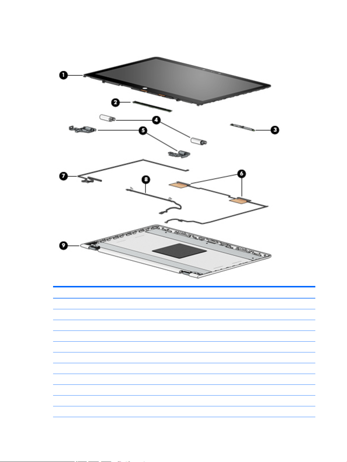
Display assembly subcomponents
Item Component Spare part number
(1) Display Panel Kit (includes display panel cable):
15.6-in, FHD, WLED, BrightView, TouchScreen equipped with an FHD infrared camera 924530-001
15.6-in, FHD, WLED, BrightView, TouchScreen equipped with an HD non-infrared camera 925711-001
15.6-in, HD, WLED, AntiGlare, TouchScreen equipped with an HD non-infrared camera 924531-001
(2) TouchScreen board (includes G-sensor board and double-sided adhesive) 929145-001
(3) Webcam/microphone module (includes Mylar and double-sided adhesive):
FHD infrared webcam/microphone module 924477-001
HD non-infrared webcam/microphone module 924478-001
(4) Hinge cover:
Left hinge cap for use only on computer models equipped with an FHD display panel 926720-001
Right hinge cap for use only on computer models equipped with an FHD display panel 926721-001
16 Chapter 3 Illustrated parts catalog
Page 23

Item Component Spare part number
Left hinge cap for use only on computer models equipped with an HD display panel 926718-001
Right hinge cap for use only on computer models equipped with an HD display panel 926719-001
(5) Hinge (2, includes left and right display hinges):
For use only on computer models equipped with an FHD display panel 924519-001
For use only on computer models equipped with an HD display panel 924518-001
(6) WLAN antenna (includes left and right WLAN cables and transceivers) 924476-001
(7) Display panel cable (includes the webcam/microphone module cable)
For use only on computer models equipped with an FHD infrared webcam/
microphone module
For use only on computer models equipped with an HD non-infrared webcam/
microphone module
(8) TouchScreen board cable (includes the G-sensor board cable) 924512-001
(9) Display enclosure (includes rubber padding and shielding):
For use only on computer models equipped with an FHD display assembly:
In natural silver nish 924501-001
In silk gold nish 924502-001
For use only on computer models equipped with an HD display assembly:
In natural silver nish 924499-001
In silk gold nish 924500-001
924507-001
924508-001
Display assembly subcomponents 17
Page 24

Miscellaneous parts
Component Spare part number
AC adapter:
For use only on computer models with model number 15-br1xx:
90-W AC adapter (PFC, S-3P, 4.5-mm) 710413-001
For use on all computer models:
65-W HP Smart AC adapter (non-PFC, EM, RC, 4.5-mm) 913691-850
65-W AC adapter (non-PFC, S-3P, 4.5-mm) 710412-001
45-W HP Smart AC adapter (non-PFC, RC, 4.5-mm, non-slim) 741553-850
HP HDMI-to-VGA adapter 701943-001
HP external DVD±RW DL SuperMulti Drive 747080-001
HP USB-to-Gigabit RJ45 adapter 829941-001
HP USB–C-to-USB–A dongle 833960-001
Power cord (C5 connector, 1.00-m):
For use in Argentina 920688-003
For use in Australia 920688-011
For use in Denmark 920688-007
For use in Europe 920688-005
For use in India 920688-016
For use in Israel 920688-008
For use in Italy 920688-002
For use in North America 920688-001
For use in the People’s Republic of China 920688-014
For use in South Africa 920688-010
For use in Switzerland 920688-009
For use in the United Kingdom and Singapore 920688-006
Rubber Foot Kit (includes bottom cover rear feet):
In natural silver nish 924886-001
In silk gold nish 924887-001
Screw Kit 924537-001
Screw Mylar Kit (includes Mylar screw cover):
In natural silver nish 924534-001
In silk gold nish 924535-001
Stylus (active pen in Pike silver nish 910942-001
18 Chapter 3 Illustrated parts catalog
Page 25

4 Removal and replacement preliminary
requirements
Tools required
You will need the following tools to complete the removal and replacement procedures:
●
Flat-bladed screw driver
●
Magnetic screw driver
●
Phillips P0 screw driver
Service considerations
The following sections include some of the considerations that you must keep in mind during disassembly
and assembly procedures.
NOTE: As you remove each subassembly from the computer, place the subassembly (and all accompanying
screws) away from the work area to prevent damage.
Plastic parts
CAUTION: Using excessive force during disassembly and reassembly can damage plastic parts. Use care
when handling the plastic parts. Apply pressure only at the points designated in
the maintenance instructions.
Cables and connectors
CAUTION: When servicing the computer, be sure that cables are placed in their proper locations during
the reassembly process. Improper cable placement can damage the computer.
Cables must be handled with extreme care to avoid damage. Apply only the tension required to unseat or seat
the cables during removal and insertion. Handle cables by the connector whenever possible. In all cases, avoid
bending, twisting, or tearing cables. Be sure that cables are routed in such a way that they cannot be caught
or snagged by parts being removed or replaced. Handle ex cables with extreme care; these cables tear
easily.
Tools required 19
Page 26

Drive handling
CAUTION: Drives are fragile components that must be handled with care. To prevent damage to
the computer, damage to a drive, or loss of information, observe these precautions:
Before removing or inserting a drive, shut down the computer. If you are unsure whether the computer is o
or in Hibernation, turn the computer on, and then shut it down through the operating system.
Before handling a drive, be sure that you are discharged of static electricity. While handling a drive, avoid
touching the connector.
Before removing a diskette drive or optical drive, be sure that a diskette or disc is not in the drive and be sure
that the optical drive tray is closed.
Handle drives on surfaces covered with at least one inch of shock-proof foam.
Avoid dropping drives from any height onto any surface.
After removing drive, place it in a static-proof bag.
Avoid exposing a drive to products that have magnetic elds, such as monitors or speakers.
Avoid exposing a drive to temperature extremes or liquids.
If a drive must be mailed, place the drive in a bubble pack mailer or other suitable form of protective
packaging and label the package “FRAGILE.”
20 Chapter 4 Removal and replacement preliminary requirements
Page 27

Grounding guidelines
Electrostatic discharge damage
Electronic components are sensitive to electrostatic discharge (ESD). Circuitry design and structure determine
the degree of sensitivity. Networks built into many integrated circuits provide some protection, but in many
cases, ESD contains enough power to alter device parameters or melt silicon junctions.
A discharge of static electricity from a nger or other conductor can destroy static-sensitive devices or
microcircuitry. Even if the spark is neither felt nor heard, damage may have occurred.
An electronic device exposed to ESD may not be aected at all and can work perfectly throughout a normal
cycle. Or the device may function normally for a while, then degrade in the internal layers, reducing its
life expectancy.
CAUTION: To prevent damage to the computer when you are removing or installing internal components,
observe these precautions:
Keep components in their electrostatic-safe containers until you are ready to install them.
Before touching an electronic component, discharge static electricity by using the guidelines described in
this section.
Avoid touching pins, leads, and circuitry. Handle electronic components as little as possible.
If you remove a component, place it in an electrostatic-safe container.
The following table shows how humidity aects the electrostatic voltage levels generated by
dierent activities.
CAUTION: A product can be degraded by as little as 700 V.
Typical electrostatic voltage levels
Relative humidity
Event 10% 40% 55%
Walking across carpet 35,000 V 15,000 V 7,500 V
Walking across vinyl oor 12,000 V 5,000 V 3,000 V
Motions of bench worker 6,000 V 800 V 400 V
Removing DIPS from plastic tube 2,000 V 700 V 400 V
Removing DIPS from vinyl tray 11,500 V 4,000 V 2,000 V
Removing DIPS from Styrofoam 14,500 V 5,000 V 3,500 V
Removing bubble pack from PCB 26,500 V 20,000 V 7,000 V
Packing PCBs in foam-lined box 21,000 V 11,000 V 5,000 V
Grounding guidelines 21
Page 28

Packaging and transporting guidelines
Follow these grounding guidelines when packaging and transporting equipment:
●
To avoid hand contact, transport products in static-safe tubes, bags, or boxes.
●
Protect ESD-sensitive parts and assemblies with conductive or approved containers or packaging.
●
Keep ESD-sensitive parts in their containers until the parts arrive at static-free workstations.
●
Place items on a grounded surface before removing items from their containers.
●
Always be properly grounded when touching a component or assembly.
●
Store reusable ESD-sensitive parts from assemblies in protective packaging or nonconductive foam.
●
Use transporters and conveyors made of antistatic belts and roller bushings. Be sure that mechanized
equipment used for moving materials is wired to ground and that proper materials are selected to avoid
static charging. When grounding is not possible, use an ionizer to dissipate electric charges.
Workstation guidelines
Follow these grounding workstation guidelines:
●
Cover the workstation with approved static-shielding material.
●
Use a wrist strap connected to a properly grounded work surface and use properly grounded tools
and equipment.
●
Use conductive eld service tools, such as cutters, screw drivers, and vacuums.
●
When xtures must directly contact dissipative surfaces, use xtures made only of static-safe materials.
●
Keep the work area free of nonconductive materials, such as ordinary plastic assembly aids
and Styrofoam.
●
Handle ESD-sensitive components, parts, and assemblies by the case or PCM laminate. Handle these
items only at static-free workstations.
●
Avoid contact with pins, leads, or circuitry.
●
Turn o power and input signals before inserting or removing connectors or test equipment.
22 Chapter 4 Removal and replacement preliminary requirements
Page 29

Equipment guidelines
Grounding equipment must include either a wrist strap or a foot strap at a grounded workstation.
●
When seated, wear a wrist strap connected to a grounded system. Wrist straps are exible straps with a
minimum of one megohm ±10% resistance in the ground cords. To provide proper ground, wear a strap
snugly against the skin at all times. On grounded mats with banana-plug connectors, use alligator clips
to connect a wrist strap.
●
When standing, use foot straps and a grounded oor mat. Foot straps (heel, toe, or boot straps) can be
used at standing workstations and are compatible with most types of shoes or boots. On conductive
oors or dissipative oor mats, use foot straps on both feet with a minimum of one megohm resistance
between the operator and ground. To be
The following grounding equipment is recommended to prevent electrostatic damage:
●
Antistatic tape
●
Antistatic smocks, aprons, and sleeve protectors
●
Conductive bins and other assembly or soldering aids
●
Nonconductive foam
●
Conductive computerop workstations with ground cords of one megohm resistance
●
Static-dissipative tables or oor mats with hard ties to the ground
●
Field service kits
eective, the conductive must be worn in contact with the skin.
●
Static awareness labels
●
Material-handling packages
●
Nonconductive plastic bags, tubes, or boxes
●
Metal tote boxes
●
Electrostatic voltage levels and protective materials
The following table lists the shielding protection provided by antistatic bags and oor mats.
Material Use Voltage protection level
Antistatic plastics Bags 1,500 V
Carbon-loaded plastic Floor mats 7,500 V
Metallized laminate Floor mats 5,000 V
Grounding guidelines 23
Page 30

5 Removal and replacement procedures
This chapter provides removal and replacement procedures for Authorized Service Provider only parts.
CAUTION: Components described in this chapter should only be accessed by an authorized service provider.
Accessing these parts can damage the computer or void the warranty.
CAUTION: This computer does not have user-replaceable parts. Only HP authorized service providers should
perform the removal and replacement procedures described here. Accessing the internal part could damage
the computer or void the warranty.
Component replacement procedures
NOTE: Details about your computer, including model, serial number, product key, and length of warranty,
are on the service tag at the bottom of your computer. See Labels on page 9 for details.
NOTE: HP continually improves and changes product parts. For complete and current information on
supported parts for your computer, go to http://partsurfer.hp.com, select your country or region, and then
follow the on-screen instructions.
There are as many as 58 screws that must be removed, replaced, and/or loosened when servicing Authorized
Service Provider only parts. Make special note of each screw size and location during removal
and replacement.
Keyboard/top cover
For use in country/region Spare part number For use in country/region Spare part number
In ash silver nish with backlight for use only on computer models equipped with a graphics subsystem with discrete memory
For use in Canada 924525-DB1 For use in the United States 924525-001
In ash silver nish with backlight for use only on computer models equipped with a graphics subsystem with UMA memory
For use in Canada 924524-DB1 For use in the United States 924525-001
In ash silver nish for use only on computer models equipped with a graphics subsystem with discrete memory
For use in Belgium 924523-A41 For use in Latin America 924523-161
For use in Bulgaria 924523-261 For use in the Netherlands 924523-B31
For use in Canada 924523-DB1 For use in Portugal 924523-131
For use in the Czech Republic
and Slovakia
For use in Denmark, Finland,
and Norway
For use in France 924523-051 For use in Saudi Arabia 924523-171
(includes backlight cable and keyboard cable):
(includes backlight cable and keyboard cable):
(includes keyboard cable):
924523-FL1 For use in Romania 924523-271
924523-DH1 For use in Russia 924523-251
For use in Germany 924523-041 For use in Slovenia 924523-BA1
24 Chapter 5 Removal and replacement procedures
Page 31

For use in country/region Spare part number For use in country/region Spare part number
For use in Greece 924523-151 For use in Spain 924523-071
For use in Hungary 924523-211 For use in Switzerland 924523-BG1
For use in India 924523-002 For use in Turkey 924523-141
For use in Israel 924523-BB1 For use in the United Kingdom 924523-031
For use in Italy 924523-061 For use in the United States 924523-001
In ash silver nish for use only on computer models equipped with a graphics subsystem with UMA memory (includes keyboard cable):
For use in Belgium 924522-A41 For use in Latin America 924522-161
For use in Bulgaria 924522-261 For use in the Netherlands 924522-B31
For use in Canada 924522-DB1 For use in Portugal 924522-131
For use in the Czech Republic
and Slovakia
For use in Denmark, Finland,
and Norway
For use in France 924522-051 For use in Saudi Arabia 924522-171
For use in Germany 924522-041 For use in Slovenia 924522-BA1
For use in Greece 924522-151 For use in Spain 924522-071
For use in Hungary 924522-211 For use in Switzerland 924522-BG1
For use in India 924522-002 For use in Turkey 924522-141
For use in Israel 924522-BB1 For use in the United Kingdom 924522-031
For use in Italy 924522-061 For use in the United States 924522-001
924522-FL1 For use in Romania 924522-271
924522-DH1 For use in Russia 924522-251
Before disassembling the computer, follow these steps:
1. Shut down the computer. If you are unsure whether the computer is o or in Hibernation, turn
the computer on, and then shut it down through the operating system.
2. Disconnect all external devices connected to the computer.
3. Disconnect the power from the computer by rst unplugging the power cord from the AC outlet, and
then unplugging the AC adapter from the computer.
Remove the keyboard/top cover:
1. Turn the computer upside down on a at surface.
2. Position the computer with the front toward you.
3. Remove the rear rubber feet (1).
The rear rubber feet are included in the Rubber Foot Kits, spare part numbers 924886-001 (in natural
silver nish) and 924887-001 (in silk gold nish).
4. Remove the Mylar screw cover (2).
The Mylar screw cover is included in the Screw Mylar Kit, spare part numbers 924834-001 (in natural
silver nish) and 924835-001 (in silk gold nish).
Component replacement procedures 25
Page 32

5. Remove the four Phillips PM2.0×4.9 screws (3) and the two Phillips PM2.5×7.6 screws (4) that secure
the keyboard/top cover to the base enclosure.
6. Turn the computer right side up.
7. Open the computer and position it on its left side with the bottom toward you.
8. Insert a keyboard release tool (1) into the empty screw holes under the rubber feet.
9. Press on the keyboard release tool until the keyboard/top cover (2) releases from the computer.
26 Chapter 5 Removal and replacement procedures
Page 33

10. Lift the front edge of the keyboard/top cover (1) until the keyboard cable, backlight cable, and
TouchPad cable connectors are accessible.
11. Release the zero insertion force (ZIF) connector (2) to which keyboard cable is connected, and then
disconnect the keyboard cable from the system board.
12. Release the ZIF connector (3) to which backlight cable is connected, and then disconnect
the backlight cable from the system board.
13. Release the ZIF connector (4) to which TouchPad cable is connected, and then disconnect
the TouchPad cable from the system board.
14. Remove the keyboard/top cover.
Reverse this procedure to install the keyboard/top cover.
Component replacement procedures 27
Page 34

TouchPad cable
NOTE: The TouchPad cable is available using spare part number 924509-001.
Before removing the TouchPad cable, follow these steps:
1. Shut down the computer. If you are unsure whether the computer is o or in Hibernation, turn
the computer on, and then shut it down through the operating system.
2. Disconnect all external devices connected to the computer.
3. Disconnect the power from the computer by rst unplugging the power cord from the AC outlet, and
then unplugging the AC adapter from the computer.
4. Remove the keyboard/top cover (see Keyboard/top cover on page 24).
Remove the TouchPad cable:
1. Release the ZIF connector (1) to which TouchPad cable is connected, and then disconnect
the TouchPad cable (2) from the TouchPad.
2. Detach the TouchPad cable (3) from the keyboard/top cover. (The TouchPad cable is attached to
the keyboard/top cover with double-sided adhesive.)
3. Remove the TouchPad cable.
Reverse this procedure to install the TouchPad cable.
28 Chapter 5 Removal and replacement procedures
Page 35

TouchPad
NOTE: The TouchPad spare part kit does not include the TouchPad bracket or TouchPad cable. The TouchPad
bracket is available using spare part number 924517-001. The TouchPad cable is available using spare part
number 924509-001.
Before removing the TouchPad, follow these steps:
1. Shut down the computer. If you are unsure whether the computer is o or in Hibernation, turn
2. Disconnect all external devices connected to the computer.
3. Disconnect the power from the computer by rst unplugging the power cord from the AC outlet, and
4. Remove the keyboard/top cover (see Keyboard/top cover on page 24).
Remove the TouchPad:
1. Turn the keyboard/top cover upside down with the front toward you.
Description Spare part number
TouchPad 924529-001
the computer on, and then shut it down through the operating system.
then unplugging the AC adapter from the computer.
2. Remove the four Phillips PM2.0×2.8 screws (1) that secure the TouchPad bracket to the keyboard/
top cover.
3. Remove the TouchPad bracket (2).
4. Remove the three Phillips PM2.0×2.3 broad head screws (1) that secure the TouchPad to the keyboard/
top cover.
Component replacement procedures 29
Page 36

5. Remove the TouchPad (2).
Reverse this procedure to install the TouchPad.
Battery
Description Spare part number
3-cell, 48-WHr, 4.2-AHr, Li-ion battery 916812-855
Before removing the battery, follow these steps:
1. Shut down the computer. If you are unsure whether the computer is o or in Hibernation, turn
the computer on, and then shut it down through the operating system.
2. Disconnect all external devices connected to the computer.
3. Disconnect the power from the computer by rst unplugging the power cord from the AC outlet, and
then unplugging the AC adapter from the computer.
4. Remove the keyboard/top cover (see Keyboard/top cover on page 24).
Remove the battery:
1. Release the ZIF connector (1) to which audio jack board cable is connected, and then disconnect
the audio jack board cable (2) from the system board.
2. Detach the audio jack board cable (2) from the battery. (The audio jack board cable is attached to
the battery with double-sided adhesive.)
3. Remove the seven Phillips PM2.0×4.6 screws (3) that secure the battery to the computer.
30 Chapter 5 Removal and replacement procedures
Page 37

4. Remove the battery (4).
Reverse this procedure to install the battery.
Hard drive
NOTE: The hard drive spare part kit does not include the hard drive rubber sleeve. The hard drive rubber
sleeve is available using spare part number 924283-001.
Description Spare part number
1-TB, 5400-rpm, SATA, 8-GB hybrid hard drive 924036-856
1-TB, 5400-rpm, SATA hard drive 762888-859
500-GB, 5400-rpm, SATA, 8-GB hybrid hard drive 731863-858
500-GB, 5400-rpm, SATA hard drive 683839-859
Before removing the hard drive, follow these steps:
1. Shut down the computer. If you are unsure whether the computer is o or in Hibernation, turn
2. Disconnect all external devices connected to the computer.
3. Disconnect the power from the computer by rst unplugging the power cord from the AC outlet, and
4. Remove the keyboard/top cover (see Keyboard/top cover on page 24).
the computer on, and then shut it down through the operating system.
then unplugging the AC adapter from the computer.
5. Remove the battery (see Battery on page 30).
Remove the hard drive:
Component replacement procedures 31
Page 38

1. Release the ZIF connector (1) to which the hard drive cable is connected, and then disconnect the hard
drive cable from the system board.
2. Detach the hard drive cable (2) from the base enclosure. (The hard drive cable is attached to the base
enclosure with double-sided adhesive.)
3. Use the tab (3) on the hard drive rubber sleeve to remove the hard drive.
4. If it is necessary to remove the hard drive from the rubber sleeve, spread the open end of the rubber
sleeve (1), and then remove the hard drive (2).
Reverse this procedure to reassemble and install the hard drive.
32 Chapter 5 Removal and replacement procedures
Page 39

Audio jack board cable
NOTE: The audio jack board cable is available using spare part number 924510-001.
Before removing the audio jack board cable, follow these steps:
1. Shut down the computer. If you are unsure whether the computer is o or in Hibernation, turn
the computer on, and then shut it down through the operating system.
2. Disconnect all external devices connected to the computer.
3. Disconnect the power from the computer by rst unplugging the power cord from the AC outlet, and
then unplugging the AC adapter from the computer.
4. Remove the keyboard/top cover (see Keyboard/top cover on page 24).
5. Remove the battery (see Battery on page 30).
Remove the audio jack board cable:
1. Release the ZIF connector (1) to which audio jack board cable is connected, and then disconnect
the audio jack board cable (2) from the audio jack board.
2. Remove the audio jack board cable.
Reverse this procedure to install the audio jack board cable.
Component replacement procedures 33
Page 40

Audio jack board
NOTE: The audio jack board spare part kit does not include the audio jack board cable. The audio jack
board cable is available using spare part number 924278-001.
Description Spare part number
Audio jack board (includes audio jack, volume control actuators, and hard drive activity light; does not
include audio jack board cable)
924527-001
Before removing the audio jack board, follow these steps:
1. Shut down the computer. If you are unsure whether the computer is o or in Hibernation, turn
the computer on, and then shut it down through the operating system.
2. Disconnect all external devices connected to the computer.
3. Disconnect the power from the computer by rst unplugging the power cord from the AC outlet, and
then unplugging the AC adapter from the computer.
4. Remove the keyboard/top cover (see Keyboard/top cover on page 24).
5. Remove the battery (see Battery on page 30).
Remove the audio jack board:
1. Remove the two Phillips PM2.0×4.6 screws (1) that secure the audio jack board to the base enclosure.
2. Remove the audio jack board (2).
Reverse this procedure to install the audio jack board.
34 Chapter 5 Removal and replacement procedures
Page 41

Power button board cable
NOTE: The power button board cable is available using spare part number 924511-001.
Before removing the audio jack board cable, follow these steps:
1. Shut down the computer. If you are unsure whether the computer is o or in Hibernation, turn
the computer on, and then shut it down through the operating system.
2. Disconnect all external devices connected to the computer.
3. Disconnect the power from the computer by rst unplugging the power cord from the AC outlet, and
then unplugging the AC adapter from the computer.
4. Remove the keyboard/top cover (see Keyboard/top cover on page 24).
5. Remove the battery (see Battery on page 30).
Remove the power button board cable:
1. Release the ZIF connector (1) to which power button board cable is connected, and then disconnect
the power button board cable from the system board.
2. Release the ZIF connector (2) to which power button board cable is connected, and then disconnect
the power button board cable from the power button board.
3. Detach the power button board cable (3) from the fan. (The power button board cable is attached to
the fan with double-sided adhesive.)
4. Remove the power button board cable.
Reverse this procedure to install the power button board cable.
Component replacement procedures 35
Page 42

Power button board
NOTE: The power button board spare part kit does not include the power button board cable. The power
button board cable is available using spare part number 924511-001.
Description Spare part number
Power button board 924526-001
Before removing the power button board, follow these steps:
1. Shut down the computer. If you are unsure whether the computer is o or in Hibernation, turn
the computer on, and then shut it down through the operating system.
2. Disconnect all external devices connected to the computer.
3. Disconnect the power from the computer by rst unplugging the power cord from the AC outlet, and
then unplugging the AC adapter from the computer.
4. Remove the keyboard/top cover (see Keyboard/top cover on page 24).
5. Remove the battery (see Battery on page 30).
Remove the power button board:
1. Release the ZIF connector (1) to which power button board cable is connected, and then disconnect
the power button board cable from the system board.
2. Detach the power button board cable (2) from the fan. (The power button board cable is attached to
the fan with double-sided adhesive.)
3. Remove the Phillips PM2.0×4.6 screw (3) that secures the power button board to the base enclosure.
4. Remove the power button board (4).
Reverse this procedure to install the power button board.
36 Chapter 5 Removal and replacement procedures
Page 43

Speakers
Before removing the speakers, follow these steps:
1. Turn o the computer. If you are unsure whether the computer is o or in Hibernation, turn
2. Disconnect the power from the computer by rst unplugging the power cord from the AC outlet, and
3. Disconnect all external devices from the computer.
4. Remove the keyboard/top cover (see Keyboard/top cover on page 24).
5. Remove the battery (see Battery on page 30).
Remove the speakers:
1. Disconnect the speaker cable (1) from the system board
2. Release the display speaker cable from the retention clips (2) built into the base enclosure.
3. Remove the four Phillips PM2.0×5.5 broad head shoulder screws (3) that secure the speakers to
Description Spare part number
Speakers (includes cables and 3 rubber isolators) 924538-001
the computer on, and then shut it down through the operating system.
then unplugging the AC adapter from the computer.
the base enclosure.
4. Remove the speakers (4).
IMPORTANT: When removing the speakers, make note of the location of the four rubber isolators (5).
Failure to properly install or damage to these isolators can result in degraded speaker performance.
Reverse this procedure to install the speakers.
Component replacement procedures 37
Page 44

System board
NOTE: All system board spare part kits include a processor and replacement thermal material.
Description Spare part number
For use only on computer models with model number 15-br1xx:
Equipped with an Intel Core i7-8550U 1.80-GHz (SC turbo up to 4.00-GHz) quad core processor (8.0-GB
L3 cache, 2400-MHz FSB, 15-W), an AMD Radeon 530 R17M-M1-70 (Meso Pro) with up to 4096-MB of
discrete video memory (512-MB×16 DDR3×4 pieces), and the Windows 10 operating system
Equipped with an Intel Core i7-8550U 1.80-GHz (SC turbo up to 4.00-GHz) quad core processor (8.0-GB
L3 cache, 2400-MHz FSB, 15-W), an AMD Radeon 530 R17M-M1-70 (Meso Pro) with up to 4096-MB of
discrete video memory (512-MB×16 DDR3×4 pieces), and a non-Windows operating system
For use on all computer models:
Equipped with an Intel Core i7-7500U 2.70-GHz (SC turbo up to 3.56-GHz) dual core processor (4.0-GB L3
cache, 2133-MHz FSB, 15-W), an AMD Radeon 530 R17M-M1-70 (Meso Pro) with up to 4096-MB of
discrete video memory (512-MB×16 DDR3×4 pieces), and the Windows 10 operating system
Equipped with an Intel Core i7-7500U 2.70-GHz (SC turbo up to 3.56-GHz) dual core processor (4.0-GB L3
cache, 2133-MHz FSB, 15-W), an AMD Radeon 530 R17M-M1-70 (Meso Pro) with up to 4096-MB of
discrete video memory (512-MB×16 DDR3×4 pieces), and a non-Windows operating system
Equipped with an Intel Core i5-7200U 2.56-GHz (SC turbo up to 3.10-GHz) dual core processor (3.0-GB L3
cache, 2133-MHz FSB, 15-W), an AMD Radeon 530 R17M-M1-70 (Meso Pro) with up to 2048-MB of
discrete video memory (256-MB×16 DDR3×4 pieces), and the Windows 10 operating system
Equipped with an Intel Core i5-7200U 2.56-GHz (SC turbo up to 3.10-GHz) dual core processor (3.0-GB L3
cache, 2133-MHz FSB, 15-W), an AMD Radeon 530 R17M-M1-70 (Meso Pro) with up to 2048-MB of
discrete video memory (256-MB×16 DDR3×4 pieces), and a non-Windows operating system
Equipped with an Intel Core i5-7200U 2.56-GHz (SC turbo up to 3.10-GHz) dual core processor (3.0-GB L3
cache, 2133-MHz FSB, 15-W), an Intel HD Graphics 620 subsystem with UMA video memory, and
the Windows 10 operating system for use only computer models equipped with an infrared camera
Equipped with an Intel Core i5-7200U 2.56-GHz (SC turbo up to 3.10-GHz) dual core processor (3.0-GB L3
cache, 2133-MHz FSB, 15-W), an Intel HD Graphics 620 subsystem with UMA video memory, and a nonWindows operating system for use only computer models equipped with an infrared camera
936031-601
936031-001
924080-601
924080-001
924081-601
924081-001
924077-601
924077-001
Equipped with an Intel Core i3-7100U 2.40-GHz dual core processor (3.0-GB L3 cache, 2133-MHz FSB,
15-W), an AMD Radeon 530 R17M-M1-70 (Meso Pro) with up to 2048-MB of discrete video memory
(256-MB×16 DDR3×4 pieces), and the Windows 10 operating system
Equipped with an Intel Core i3-7100U 2.40-GHz dual core processor (3.0-GB L3 cache, 2133-MHz FSB,
15-W), an AMD Radeon 530 R17M-M1-70 (Meso Pro) with up to 2048-MB of discrete video memory
(256-MB×16 DDR3×4 pieces), and a non-Windows operating system
Equipped with an Intel Core i3-7100U 2.40-GHz dual core processor (3.0-GB L3 cache, 2133-MHz FSB,
15-W), an Intel HD Graphics 620 subsystem with UMA video memory, and the Windows 10
operating system
Equipped with an Intel Core i3-7100U 2.40-GHz dual core processor (3.0-GB L3 cache, 2133-MHz FSB,
15-W), an Intel HD Graphics 620 subsystem with UMA video memory, and a non-Windows
operating system
Equipped with an Intel Pentium 4415U 2.36-GHz dual core processor (2.0-GB L3 cache, 2133-MHz FSB,
15-W), an Intel HD Graphics subsystem with UMA video memory, and the Windows 10 operating system
Equipped with an Intel Pentium 4415U 2.36-GHz dual core processor (2.0-GB L3 cache, 2133-MHz FSB,
15-W), an Intel HD Graphics subsystem with UMA video memory, and a non-Windows operating system
38 Chapter 5 Removal and replacement procedures
924082-601
924082-001
924078-601
924078-001
924079-601
924079-001
Page 45

Before removing the system board, follow these steps:
1. Shut down the computer. If you are unsure whether the computer is o or in Hibernation, turn
the computer on, and then shut it down through the operating system.
2. Disconnect all external devices connected to the computer.
3. Disconnect the power from the computer by rst unplugging the power cord from the AC outlet, and
then unplugging the AC adapter from the computer.
4. Remove the keyboard/top cover (see Keyboard/top cover on page 24).
5. Remove the battery (see Battery on page 30).
6. Remove the speakers (see Speakers on page 37).
When replacing the system board, be sure to remove the following components from the defective system
board and install them on the replacement system board:
●
WLAN module (see WLAN module on page 42)
●
Fan/heat sink assembly (see Fan/heat sink assembly on page 43)
●
Memory modules (see Memory module on page 45)
Remove the system board:
1. Release the adhesive strip (1) that secures the display panel cable connector to the system board.
2. Release the ZIF connector (2) to which display panel cable is connected, and then disconnect the display
panel cable from the system board.
3. Release the display panel cable from the retention clips (3) and routing channel built into the fan/heat
sink assembly.
4. Release the ZIF connector (4) to which power button board cable is connected, and then disconnect
the power button board cable from the system board.
5. Disconnect the wireless antenna cables (5) from the WLAN module.
NOTE: The #1/white WLAN antenna cable connects to the WLAN module "#1/Main" terminal. The #2/
black WLAN antenna cable connects to the WLAN module "#2/Aux" terminal.
6. Release the adhesive strip (6) that secures the TouchScreen cable connector to the system board.
7. Release the ZIF connector (7) to which TouchScreen cable is connected, and then disconnect
the TouchScreen cable from the system board.
8. Disconnect the power connector cable (8) from the system board.
Component replacement procedures 39
Page 46

9. Release the ZIF connector (9) to which hard drive cable is connected, and then disconnect the hard
drive cable from the system board.
10. Remove the 10 Phillips PM2.0×4.6 screws (1) that secure the system board to the base enclosure.
11. Remove the Phillips PM2.0×3.7 screw (2) that secures the WLAN module to the base enclosure.
12. Lift the left side of the system board (1) until it rests at an angle.
40 Chapter 5 Removal and replacement procedures
Page 47

13. Remove the system board (2) by sliding it up and to the left at an angle.
Reverse this procedure to install the system board.
Component replacement procedures 41
Page 48

WLAN module
Description Spare part number
Intel Dual Band Wireless-AC 7265 802.11 AC 2×2 WiFi + Bluetooth 4.2 Combo Adapter (non-vPro) 901229-855
Intel Dual Band Wireless-AC 3168 802.11AC 1×1 WiFi + Bluetooth 4.2 Combo Adapter (non-vPro) 863934-855
CAUTION: To prevent an unresponsive system, replace the wireless module only with a wireless module
authorized for use in the computer by the governmental agency that regulates wireless devices in your
country or region. If you replace the module and then receive a warning message, remove the module to
restore device functionality, and then contact technical support.
Before removing the WLAN module, follow these steps:
1. Turn o the computer. If you are unsure whether the computer is o or in Hibernation, turn
the computer on, and then shut it down through the operating system.
2. Disconnect the power from the computer by rst unplugging the power cord from the AC outlet, and
then unplugging the AC adapter from the computer.
3. Disconnect all external devices from the computer.
4. Remove the keyboard/top cover (see Keyboard/top cover on page 24), and then remove
the following components:
a. Battery (see Battery on page 30)
b. Speakers (see Speakers on page 37)
c. System board (see System board on page 38)
Remove the WLAN module:
1. Turn the system board upside down with the front toward you.
2. Remove the WLAN module by pulling the module away from the slot at an angle.
NOTE: WLAN modules are designed with a notch to prevent incorrect insertion.
Reverse this procedure to install the WLAN module.
42 Chapter 5 Removal and replacement procedures
Page 49

Fan/heat sink assembly
NOTE: The fan/heat sink assembly spare part kit includes the fan cable and replacement thermal material.
Description Spare part number
For use only on computer models equipped with a graphics subsystem with discrete memory 924514-001
For use only on computer models equipped with a graphics subsystem with UMA memory 924513-001
Before removing the fan/heat sink assembly, follow these steps:
1. Turn o the computer. If you are unsure whether the computer is o or in Hibernation, turn
the computer on, and then shut it down through the operating system.
2. Disconnect the power from the computer by rst unplugging the power cord from the AC outlet, and
then unplugging the AC adapter from the computer.
3. Disconnect all external devices from the computer.
4. Remove the keyboard/top cover (see Keyboard/top cover on page 24), and then remove
the following components:
a. Battery (see Battery on page 30)
b. Speakers (see Speakers on page 37)
c. System board (see System board on page 38)
Remove the fan/heat sink assembly:
1. Turn the system board upside down with the front toward you.
2. Disconnect the fan cable (1) from the system board.
3. Detach the piece of tape (2) that secures the fan cable to the system board.
4. Loosen the six Phillips PM2.0×6.2 captive screws (3) that secure the fan/heat sink assembly to
the system board.
NOTE: Computer models equipped with a graphics subsystem with UMA memory will only have four
screws securing the fan/heat sink assembly to the system board.
Component replacement procedures 43
Page 50

5. Remove the fan/heat sink assembly (4).
NOTE: The thermal material must be thoroughly cleaned from the surfaces of the fan/heat sink
assembly and the system board components each time the fan/heat sink assembly is removed.
Replacement thermal material is included with the fan/heat sink assembly and system board
spare part kits.
Thermal paste is used on the processor (1) and the heat sink section (2) that services it. Thermal paste
is also used on the VGA component (3) and the heat sink section (4) that services it.
NOTE: Computer models equipped with a graphics subsystem with UMA memory will not have
the components identied by callouts 3 and 4 present on the system board and fan/heat sink assembly.
Reverse this procedure to install the fan/heat sink assembly.
44 Chapter 5 Removal and replacement procedures
Page 51

Memory module
NOTE: The memory module spare part kit does not include the memory module bracket. The memory
module bracket is available using spare part number 925378-001.
NOTE: Primary and expansion memory is installed in a side-by-side conguration in the bottom of
the computer. If only one memory module is installed, it must be installed in the socket labeled 1.
Description Spare part number
8-MB, DDR4-2400, 1.2-V 820570-005
4-MB, DDR4-2400, 1.2-V 862397-855
2-MB, DDR4-2133, 1.2-V 864271-855
Update BIOS before adding memory modules
Before adding new memory, make sure you update the computer to the latest BIOS.
CAUTION: Failure to update the computer to the latest BIOS prior to installing new memory may result in
various system problems.
To update BIOS:
1. Navigate to www.hp.com.
2. Click Support & Drivers, and then click Drivers & Software.
3. In the Enter a product name/number box, type the computer model information, and then click Search.
4. Click the link for the computer model.
5. Select the operating system, and then click Next.
6. Under Step 2: Select a Download, click the BIOS link.
7. Click the link for the most recent BIOS.
8. Click the Download button, and then follow the on-screen instructions.
Before removing the memory module, follow these steps:
1. Turn o the computer. If you are unsure whether the computer is o or in Hibernation, turn
the computer on, and then shut it down through the operating system.
2. Disconnect the power from the computer by rst unplugging the power cord from the AC outlet, and
then unplugging the AC adapter from the computer.
3. Disconnect all external devices from the computer.
4. Remove the keyboard/top cover (see Keyboard/top cover on page 24), and then remove
the following components:
a. Battery (see Battery on page 30)
b. Speakers (see Speakers on page 37)
c. System board (see System board on page 38)
Remove the memory module:
1. Turn the system board upside down with the front toward you.
Component replacement procedures 45
Page 52

2. Remove the memory module shield.
The memory module shield is available using spare part number 925378-001.
3. Spread the retaining tabs (1) on each side of the memory module slot to release the memory module.
(The edge of the module opposite the slot rises away from the computer.)
4. Remove the memory module (2) by pulling the module away from the slot at an angle.
NOTE: Memory modules are designed with a notch to prevent incorrect insertion.
Reverse this procedure to install a memory module.
46 Chapter 5 Removal and replacement procedures
Page 53

Power connector cable
NOTE: The power connector cable spare part kit does not include the power connector cable bracket. The
power connector cable bracket is available using spare part number 924516-001.
Description Spare part number
Power connector cable (does not include bracket) 808155-024
Before removing the power connector cable, follow these steps:
1. Shut down the computer. If you are unsure whether the computer is o or in Hibernation, turn
the computer on, and then shut it down through the operating system.
2. Disconnect all external devices connected to the computer.
3. Disconnect the power from the computer by rst unplugging the power cord from the AC outlet, and
then unplugging the AC adapter from the computer.
4. Remove the keyboard/top cover (see Keyboard/top cover on page 24), and then remove
the following components:
a. Battery (see Battery on page 30)
b. Speakers (see Speakers on page 37)
c. System board (see System board on page 38)
Remove the power connector cable:
1. Lift the right side of the power connector cable bracket (1) to release the bracket from
the power connector.
2. Remove the power connector cable bracket (2).
3. Remove the power connector cable (3).
Component replacement procedures 47
Page 54

Reverse this procedure to install the power connector cable.
Display assembly
NOTE: The display assembly is spared at the subcomponent level. For display assembly spare part
information, see the individual removal subsections.
Before removing the display assembly, follow these steps:
1. Shut down the computer. If you are unsure whether the computer is o or in Hibernation, turn
the computer on, and then shut it down through the operating system.
2. Disconnect all external devices connected to the computer.
3. Disconnect the power from the computer by rst unplugging the power cord from the AC outlet, and
then unplugging the AC adapter from the computer.
4. Remove the keyboard/top cover (see Keyboard/top cover on page 24), and then remove
the following components:
a. Battery (see Battery on page 30)
b. Speakers (see Speakers on page 37)
c. System board (see System board on page 38)
Remove the display assembly:
1. Remove the ve Phillips PM2.5×5.7 screws (1) the Phillips PM2.5×4.6 screw (2) that secure the display
assembly to the base enclosure.
2. Remove the display assembly (3).
3. If it is necessary to replace the display panel assembly or any of the display assembly subcomponents:
NOTE: The display panel assembly can be removed and replaced without removing the display
assembly from the base enclosure.
48 Chapter 5 Removal and replacement procedures
Page 55

a. Insert a case utility tool (1) or similar thin, plastic tool between the top edges of the display panel
assembly and the display back cover.
b. Release the top edge of the display panel assembly (2) from the display back cover.
c. Swing the display panel assembly (3) forward until it rests on the keyboard.
d. Detach the two pieces of tape (1) that secure the TouchScreen board and TouchScreen
board cables to the display panel assembly.
Component replacement procedures 49
Page 56

e. Disconnect both ends of the TouchScreen board cable (2) from the two connectors on
the TouchScreen board.
f. Release the adhesive strip (1) that secures the display panel cable connector to the display panel.
g. Disconnect the display panel cable (2) from the display panel.
h. Remove the display panel assembly (3).
The display panel assembly is available using the following spare part numbers:
●
924530-001 – 15.6-in, FHD, WLED, BrightView, TouchScreen equipped with an FHD
infrared camera
●
925711-001 – 15.6-in, FHD, WLED, BrightView, TouchScreen equipped with an HD noninfrared camera
●
924531-001 – 15.6-in, HD, WLED, AntiGlare, TouchScreen equipped with an HD noninfrared camera
50 Chapter 5 Removal and replacement procedures
Page 57

4. If it is necessary to replace the TouchScreen board:
NOTE: The TouchScreen board can be removed and replaced without removing the display assembly
from the base enclosure.
a. Remove the display panel assembly.
CAUTION: Before turning the display panel assembly upside down, make sure the work surface is
clear of tools, screws, and any other foreign objects. Failure to follow this caution can result in
damage to the display panel.
b. Turn the display panel assembly upside down with the bottom edge toward you.
c. Release the two ZIF connectors (1) to which display panel cables are connected, and then
disconnect the display panel cables from the TouchScreen board.
Component replacement procedures 51
Page 58

d. Remove the TouchScreen board (2).
The TouchScreen board is available using spare part number 929145-001 and includes the Gsensor board.
5. If it is necessary to replace the webcam/microphone module:
NOTE: The webcam/microphone module can be removed and replaced without removing the display
assembly from the base enclosure.
a. Remove the display panel assembly.
b. Disconnect the webcam/microphone module cable (1) from the webcam/microphone module.
52 Chapter 5 Removal and replacement procedures
Page 59

c. Detach the webcam/microphone module (2) from the display back cover. (The webcam/
microphone module is attached to the display back cover with double-sided adhesive.)
d. Remove the webcam/microphone module.
The webcam/microphone module is available using spare part numbers 924477-001 (FHD infrared
webcam/microphone module) and 924478-001 (HD non-infrared webcam/microphone module).
6. If it is necessary to replace the display hinges:
NOTE: It is necessary to remove the display assembly to remove and replace the display hinge.
a. Remove the display panel assembly.
b. Remove the six Phillips PM2.5×2.9 broad head screws (1) that secure the hinges to the display
back cover.
c. Rotate the hinges (2) toward the inside of the display back cover to release them from the display
back cover.
Component replacement procedures 53
Page 60

d. Remove the display hinges (3).
The display hinges are available using spare part numbers 924519-001 (for use only on computer
models equipped with an FHD display panel) and 924518-001 (for use only on computer models
equipped with an HD display panel).
7. If it is necessary to replace the display hinge covers:
NOTE: It is necessary to remove the display assembly to remove and replace the display hinge covers.
a. Remove the display panel assembly.
b. Remove the display hinge.
c. Remove the Phillips PM2.0×4.0 screw (1) that secures the hinge cover to the hinge.
d. Remove the display hinge cover (2).
The display hinge covers are available using the following spare part numbers:
●
926720-001 – Left hinge cap for use only on computer models equipped with an
FHD display panel
●
926721-001 – Right hinge cap for use only on computer models equipped with an
FHD display panel
●
926718-001 – Left hinge cap for use only on computer models equipped with an
HD display panel
●
926719-001 – Right hinge cap for use only on computer models equipped with an
HD display panel
54 Chapter 5 Removal and replacement procedures
Page 61

8. If it is necessary to replace the TouchScreen board cable:
NOTE: It is necessary to remove the display assembly to remove and replace
the TouchScreen board cable.
a. Remove the display panel assembly.
b. Remove the TouchScreen board cable from the cavity in the bottom edge of the display back cover.
The TouchScreen board cable is available using spare part number 924512-001 and includes the Gsensor board cable.
9. If it is necessary to replace the wireless antenna cables and transceivers:
a. Remove the display panel assembly.
b. Remove the right display hinge.
c. Detach the wireless antenna transceivers (1) from the display back cover. (The wireless antenna
transceivers are attached to the display back cover with double-sided adhesive.)
d. Release the shielding material (2) that secures the wireless antenna cables to the display
back cover.
e. Release the wireless antenna cables from the retention clips (3) and routing channel built into
the top, right, and bottom edges of the display back cover.
Component replacement procedures 55
Page 62

f. Remove the wireless antenna cables and transceivers (4).
The wireless antenna cables and transceivers are available using spare part number 924476-001.
10. If it is necessary to replace the display panel cable:
a. Remove the display panel assembly.
b. Remove the left display hinge.
c. Release the left wireless antenna transceiver.
d. Disconnect the webcam/microphone module cable (1) from the webcam/microphone module.
e. Release the shielding material (2) that secures the display panel cable to the display back cover.
f. Release the display panel cable from the retention clips (3) and routing channel built into the top,
left, and bottom edges of the display back cover.
56 Chapter 5 Removal and replacement procedures
Page 63

g. Remove the display panel cable (4).
The display panel cable is available using spare part numbers 924507-001 (for use only on
computer models equipped with an FHD display panel) and 924508-001 (for use only on computer
models equipped with an HD display panel) and includes the webcam/microphone module cable.
Reverse this procedure to reassemble and install the display assembly.
Component replacement procedures 57
Page 64

6 Computer Setup (BIOS), TPM, and HP Sure
Start
Using Computer Setup
Computer Setup, or Basic Input/Output System (BIOS), controls communication between all the input and
output devices on the system (such as disk drives, display, keyboard, mouse, and printer). Computer Setup
includes settings for the types of devices installed, the startup sequence of the computer, and the amount of
system and extended memory.
NOTE: Use extreme care when making changes in Computer Setup. Errors can prevent the computer from
operating properly.
Starting Computer Setup
NOTE: An external keyboard or mouse connected to a USB port can be used with Computer Setup only if USB
legacy support is enabled.
To start Computer Setup, follow these steps:
▲
Start Computer Setup.
●
Computers or tablets with keyboards:
▲
Turn on or restart the computer, and when the HP logo appears, press f10 to enter Computer
Setup.
●
Tablets without keyboards:
▲
Turn o the tablet. Press the power button in combination with the volume down button until
the Startup menu is displayed, and then tap F10 to enter Computer Setup.
Navigating and selecting in Computer Setup
●
To select a menu or a menu item, use the tab key and the keyboard arrow keys and then press enter, or
use a pointing device to select the item.
NOTE: On tablets without keyboards, you can use your nger to make selections.
●
To scroll up and down, select the up arrow or the down arrow in the upper-right corner of the screen, or
use the up arrow key or the down arrow key on the keyboard.
●
To close open dialog boxes and return to the main Computer Setup screen, press esc, and then follow
the on-screen instructions.
58 Chapter 6 Computer Setup (BIOS), TPM, and HP Sure Start
Page 65

To exit Computer Setup menus, choose one of the following methods:
●
To exit Computer Setup menus without saving your changes:
Select the Exit icon in the lower-right corner of the screen, and then follow the on-screen instructions.
– or –
Select Main, select Ignore Changes and Exit, and then press enter.
●
To save your changes and exit Computer Setup menus:
Select the Save icon in the lower-right corner of the screen, and then follow the on-screen instructions.
– or –
Select Main, select Save Changes and Exit, and then press enter.
Your changes go into eect when the computer restarts.
Restoring factory settings in Computer Setup
NOTE: Restoring defaults will not change the hard drive mode.
To return all settings in Computer Setup to the values that were set at the factory, follow these steps:
1. Start Computer Setup. See Starting Computer Setup on page 58.
2. Select Main, and then select Apply Factory Defaults and Exit.
NOTE: On select products, the selections may display Restore Defaults instead of Apply Factory
Defaults and Exit.
3. Follow the on-screen instructions.
4. To save your changes and exit, select the Save icon in the lower-right corner of the screen, and then
follow the on-screen instructions.
– or –
Select Main, select Save Changes and Exit, and then press enter.
Your changes go into eect when the computer restarts.
NOTE: Your password settings and security settings are not changed when you restore the factory settings.
Using Computer Setup 59
Page 66

Updating the BIOS
Updated versions of the BIOS may be available on the HP website.
Most BIOS updates on the HP website are packaged in compressed les called SoftPaqs.
Some download packages contain a le named Readme.txt, which contains information regarding installing
and troubleshooting the le.
Determining the BIOS version
To decide whether you need to update Computer Setup (BIOS), rst determine the BIOS version on
the computer.
BIOS version information (also known as ROM date and System BIOS) can be accessed by pressing fn+esc (if
you are already in Windows) or by using Computer Setup.
1. Start Computer Setup. See Starting Computer Setup on page 58.
2. Select Main, and then select System Information.
3. To exit Computer Setup without saving your changes, select the Exit icon in the lower-right corner of
the screen, and then follow the on-screen instructions.
– or –
Select Main, select Ignore Changes and Exit, and then press enter.
To check for later BIOS versions, see Downloading a BIOS update on page 60.
Downloading a BIOS update
CAUTION: To reduce the risk of damage to the computer or an unsuccessful installation, download and
install a BIOS update only when the computer is connected to reliable external power using the AC adapter. Do
not download or install a BIOS update while the computer is running on battery power, docked in an optional
docking device, or connected to an optional power source. During the download and installation, follow these
instructions:
Do not disconnect power on the computer by unplugging the power cord from the AC outlet.
Do not shut down the computer or initiate Sleep.
Do not insert, remove, connect, or disconnect any device, cable, or cord.
1. Type support in the taskbar search box, and then select the HP Support Assistant app.
– or –
Select the question mark icon in the taskbar.
2. Select Updates, and then select Check for updates and messages.
3. Follow the on-screen instructions.
4. At the download area, follow these steps:
a. Identify the most recent BIOS update and compare it to the BIOS version currently installed on your
computer. Make a note of the date, name, or other identier. You may need this information to
locate the update later, after it has been downloaded to your hard drive.
b. Follow the on-screen instructions to download your selection to the hard drive.
Make a note of the path to the location on your hard drive where the BIOS update is downloaded.
You will need to access this path when you are ready to install the update.
60 Chapter 6 Computer Setup (BIOS), TPM, and HP Sure Start
Page 67

NOTE: If you connect your computer to a network, consult the network administrator before installing
any software updates, especially system BIOS updates.
BIOS installation procedures vary. Follow any instructions that are revealed on the screen after the download
is complete. If no instructions are revealed, follow these steps:
1. Type file in the taskbar search box, and then select File Explorer.
2. Select your hard drive designation. The hard drive designation is typically Local Disk (C:).
3. Using the hard drive path you recorded earlier, open the folder that contains the update.
4. Double-click the le that has an .exe extension (for example, lename.exe).
The BIOS installation begins.
5. Complete the installation by following the on-screen instructions.
NOTE: After a message on the screen reports a successful installation, you can delete the downloaded le
from your hard drive.
Changing the boot order using the f9 prompt
To dynamically choose a boot device for the current startup sequence, follow these steps:
1. Access the Boot Device Options menu:
●
Computers or tablets with keyboards:
▲
Turn on or restart the computer, and when the HP logo appears, press f9 to enter the Boot
Device Options menu.
●
Tablets without keyboards:
▲
Turn o the tablet. Press the power button in combination with the volume down button until
the Startup menu is displayed, and then tap F9 to enter the Boot Device Options menu.
2. Select a boot device, then press enter.
Using Computer Setup 61
Page 68

TPM BIOS settings (select products only)
IMPORTANT: Before enabling Trusted Platform Module (TPM) functionality on this system, you must ensure
that your intended use of TPM complies with relevant local laws, regulations and policies, and approvals or
licenses must be obtained if applicable. For any compliance issues arising from your operation/usage of TPM
which violates the above mentioned requirement, you shall bear all the liabilities wholly and solely. HP will
not be responsible for any related liabilities.
TPM provides additional security for your computer. You can modify the TPM settings in Computer Setup
(BIOS).
NOTE: If you change the TPM setting to Hidden, TPM is not visible in the operating system.
To access TPM settings in Computer Setup:
1. Start Computer Setup. See Starting Computer Setup on page 58.
2. Select Security, select TPM Embedded Security, and then follow the on-screen instructions.
Using HP Sure Start (select products only)
Select computer models are congured with HP Sure Start, a technology that continuously monitors
the computer's BIOS for attacks or corruption. If the BIOS becomes corrupted or is attacked, HP Sure Start
automatically restores the BIOS to its previously safe state, without user intervention.
HP Sure Start is congured and already enabled so that most users can use the HP Sure Start default
conguration. The default conguration can be customized by advanced users.
To access the latest documentation on HP Sure Start, go to http://www.hp.com/support, and select your
country. Select Drivers & Downloads, and then follow the on-screen instructions.
62 Chapter 6 Computer Setup (BIOS), TPM, and HP Sure Start
Page 69

7 HP PC Hardware Diagnostics (UEFI)
HP PC Hardware Diagnostics is a Unied Extensible Firmware Interface (UEFI) that allows you to run diagnostic
tests to determine whether the computer hardware is functioning properly. The tool runs outside
the operating system so that it can isolate hardware failures from issues that are caused by the operating
system or other software components.
When HP PC Hardware Diagnostics (UEFI) detects a failure that requires hardware replacement, a 24-digit
Failure ID is generated. This ID can then be provided to support to help determine how to correct the problem.
NOTE: To start diagnostics on a convertible computer, your computer must be in notebook mode and you
must use the keyboard attached.
To start HP PC Hardware Diagnostics (UEFI), follow these steps:
1. Turn on or restart the computer, quickly press esc.
NOTE: The HP PC Hardware Diagnostics (UEFI) download instructions are provided in English only, and
you must use a Windows computer to download and create the HP UEFI support environment because
only .exe les are oered.
2. Press or tap f2.
The BIOS searches three places for the diagnostic tools, in the following order:
a. Connected USB drive
NOTE: To download the HP PC Hardware Diagnostics (UEFI) tool to a USB drive, see Downloading
HP PC Hardware Diagnostics (UEFI) to a USB device on page 64.
b. Hard drive
c. BIOS
3. When the diagnostic tool opens, select the type of diagnostic test you want to run, and then follow
the on-screen instructions.
NOTE: If you need to stop a diagnostic test, press esc.
63
Page 70

Downloading HP PC Hardware Diagnostics (UEFI) to a USB device
NOTE: The HP PC Hardware Diagnostics (UEFI) download instructions are provided in English only, and you
must use a Windows computer to download and create the HP UEFI support environment because only .exe
les are oered.
There are two options to download HP PC Hardware Diagnostics to a USB device.
Download the latest UEFI version
1. Go to http://www.hp.com/go/techcenter/pcdiags. The HP PC Diagnostics home page is displayed.
2. In the HP PC Hardware Diagnostics section, click the Download link, and then select Run.
Download any version of UEFI for a specic product
1. Go to http://www.hp.com/support, and then select your country. The HP Support page is displayed.
2. Click Drivers & Downloads.
3. In the text box, enter the product name, and then click Go.
– or –
Click Find Now to let HP automatically detect your product.
4. Select your computer, and then select your operating system.
5. In the Diagnostic section, follow the on-screen instructions to select and download the UEFI version
you want.
64 Chapter 7 HP PC Hardware Diagnostics (UEFI)
Page 71

8 Specications
Metric U.S.
Computer dimensions
Width 30.0 cm 11.8 in
Depth 20.6 cm 8.1 in
Height 2.1 cm 0.8 in
Weight 1.3 kg 2.9 lbs
Temperature
Operating 5°C to 35°C 41°F to 95°F
Nonoperating ‑20°C to 60°C ‑4°F to 140°F
Relative humidity (noncondensing)
Operating 10% to 90%
Nonoperating 5% to 95%
Maximum altitude (unpressurized)
Operating ‑15 m to 3,048 m ‑50 ft to 10,000 ft
Nonoperating ‑15 m to 12,192 m ‑50 ft to 40,000 ft
NOTE: Applicable product safety standards specify thermal limits for plastic surfaces. The device operates well within this range of
temperatures.
65
Page 72

9 Power cord set requirements
The wide-range input feature of the computer permits it to operate from any line voltage from 100 to 120
volts AC, or from 220 to 240 volts AC.
The 3-conductor power cord set included with the computer meets the requirements for use in the country or
region where the equipment is purchased.
Power cord sets for use in other countries and regions must meet the requirements of the country or region
where the computer is used.
Requirements for all countries
The following requirements are applicable to all countries and regions:
●
The length of the power cord set must be at least 1.0 m (3.3 ft) and no more than 2.0 m (6.5 ft).
●
All power cord sets must be approved by an acceptable accredited agency responsible for evaluation in
the country or region where the power cord set will be used.
●
The power cord sets must have a minimum current capacity of 10 amps and a nominal voltage rating of
125 or 250 V AC, as required by the power system of each country or region.
●
The appliance coupler must meet the mechanical conguration of an EN 60 320/IEC 320 Standard Sheet
C13 connector for mating with the appliance inlet on the back of the computer. Requirements for all
countries 113
Requirements for specic countries and regions
Country/region Accredited agency Applicable note number
Australia EANSW 1
Austria OVE 1
Belgium CEBC 1
Canada CSA 2
Denmark DEMKO 1
Finland FIMKO 1
France UTE 1
Germany VDE 1
Italy IMQ 1
Japan METI 3
The Netherlands KEMA 1
Norway NEMKO 1
The People's Republic of China COC 5
66 Chapter 9 Power cord set requirements
Page 73

Country/region Accredited agency Applicable note number
South Korea EK 4
Sweden CEMKO 1
Switzerland SEV 1
Taiwan BSMI 4
The United Kingdom BSI 1
The United States UL 2
1. The exible cord must be Type HO5VV-F, 3-conductor, 1.0-mm² conductor size. Power cord set ttings (appliance coupler and
wall plug) must bear the certication mark of the agency responsible for evaluation in the country or region where it will be used.
2. The exible cord must be Type SPT-3 or equivalent, No. 18 AWG, 3-conductor. The wall plug must be a two-pole grounding type
with a NEMA 5-15P (15 A, 125 V) or NEMA 6-15P (15 A, 250 V) conguration.
3. The appliance coupler, exible cord, and wall plug must bear a “T” mark and registration number in accordance with the Japanese
Dentori Law. The exible cord must be Type VCT or VCTF, 3-conductor, 1.00-mm² conductor size. The wall plug must be a twopole grounding type with a Japanese Industrial Standard C8303 (7 A, 125 V) conguration.
4. The exible cord must be Type RVV, 3-conductor, 0.75-mm² conductor size. Power cord set ttings (appliance coupler and wall
plug) must bear the certication mark of the agency responsible for evaluation in the country or region where it will be used.
5. The exible cord must be Type VCTF, 3-conductor, 0.75-mm² conductor size. Power cord set ttings (appliance coupler and wall
plug) must bear the certication mark of the agency responsible for evaluation in the country or region where it will be used.
Requirements for specic countries and regions 67
Page 74

10 Recycling
When a non-rechargeable or rechargeable battery has reached the end of its useful life, do not dispose of
the battery in general household waste. Follow the local laws and regulations in your area for battery
disposal.
HP encourages customers to recycle used electronic hardware, HP original print cartridges, and rechargeable
batteries. For more information about recycling programs, see the HP Web site at
http://www.hp.com/recycle.
68 Chapter 10 Recycling
Page 75

Index
A
AC adapter, spare part numbers 18
antenna
location 4
removal 55
spare part number 56
spare part numbers 17
audio jack board
removal 34
spare part number 13, 34
audio jack board cable
removal 33
spare part number 13, 33, 34
audio, product description 2, 3
audio-in jack 7
audio-out jack 7
B
base enclosure, spare part
numbers 15
battery
removal 30
spare part number 12, 30
BIOS
determining version 60
downloading an update 60
updating 60
bottom component 8
C
cables, service considerations 19
chipset, product description 1
components
bottom 8
display 4
left side 6
right side 7
speakers 5
TouchPad 5
computer major components 10
Computer Setup
navigating and selecting 58
restoring factory settings 59
connectors, service considerations
19
D
display assembly
removal 48
spare part numbers 48
subcomponents 16
display components 4
display enclosure, spare part
number 17
display panel assembly
removal 48
spare part numbers 50
display panel cable
removal 56
spare part numbers 17, 57
Display Panel Kit
spare part numbers 16
display panel, product description 1
display switch 4
drives
precautions 20
preventing damage 20
E
electrostatic discharge 21
equipment guidelines 23
F
fan/heat sink assembly
removal 43
spare part numbers 14, 43
G
G-sensor board cable
spare part number 55
graphics, product description 1
grounding guidelines 21
guidelines
equipment 23
grounding 21
packaging 22
transporting 22
workstation 22
H
hard drive
product description 2
removal 31
spare part numbers 13, 31
hard drive counterbalance weight,
spare part number 13
hard drive rubber sleeve
removal 32
spare part number 13, 31
HDMI port 7
HDMI-to-VGA adapter, spare part
number 18
headphone jack 7
hinge
removal 53
spare part numbers 17, 54
hinge cover
removal 54
spare part numbers 16, 54
HP PC Hardware Diagnostics (UEFI)
using 63
J
jacks
audio-in 7
audio-out 7
headphone 7
microphone 7
K
keyboard, product description 3
keyboard/top cover
removal 24
spare part numbers 11, 12, 24
L
left-side component 6
legacy support, USB 58
lights
power 7
webcam 4
Index 69
Page 76

M
memory module
product description 1, 2
removal 45
spare part numbers 14, 45
memory module bracket
spare part number 45
memory module shield
removal 46
spare part number 14, 46
microphone
location 4
product description 2, 3
microphone jack 7
model name 1
O
operating system, product
description 3
optical drive
product description 2
optical drive, spare part number 18
P
packaging guidelines 22
plastic parts, service
considerations 19
pointing device, product
description 3
ports
HDMI 7
product description 3
USB 7
power button board
removal 36
spare part number 13, 36
power button board cable
removal 35
spare part number 13, 35, 36
power connector cable
removal 47
spare part number 15, 47
power connector cable bracket
removal 47
spare part number 15, 47
power cord
set requirements 66
power light 7
power requirements, product
description 3
processor, product description 1
product description
audio 2, 3
chipset 1
display panel 1
external media cards 3
graphics 1
hard drive 2
keyboard 3
memory module 1, 2
microphone 2, 3
operating system 3
optical drive 2
pointing device 3
ports 3
power requirements 3
processors 1
product name 1
security 3
sensors 3
serviceability 3
solid-state drive 2
storage 2
video 2, 3
wireless 3
product name 1
R
removal/replacement
procedures 24
right-side components 7
rubber feet
removal 25
spare part numbers 25
Rubber Foot Kit, spare part
numbers 15, 18, 25
S
screw cover
removal 25
spare part numbers 25
Screw Kit, spare part number 18
Screw Mylar Kit, spare part
numbers 15, 18, 25
security cable slot 6
security, product description 3
sensors, product description 3
service considerations
cables 19
connectors 19
plastic parts 19
serviceability, product description 3
setup utility
navigating and selecting 58
restoring factory settings 59
solid-state drive
product description 2
spare part numbers 14
solid-state drive counterbalance
weight, spare part number
Solid-State Drive Rubber Kit, spare
part number 15
speakers
components 5
locations 5, 8
removal 37
spare part number 13, 37
storage, product description 2
stylus, spare part number 18
Sure Start
using 62
system board
removal 38
spare part numbers 13, 38
T
tools required 19
TouchPad
removal 29
spare part number 12, 29
TouchPad bracket
spare part number 12, 29
TouchPad cable
removal 28
spare part number 12, 28, 29
TouchPad component 5
TouchPad zone 5
TouchScreen board
removal 51
spare part number 16, 52
TouchScreen board cable
removal 55
spare part number 17, 55
TPM settings 62
transporting guidelines 22
U
USB legacy support 58
USB port 7
15
70 Index
Page 77

USB-to-Gigabit RJ45 adapter, spare
part number 18
USB–C-to-USB–A dongle, spare part
number 18
V
video, product description 2, 3
W
webcam light 4
webcam, location 4
webcam/microphone module
removal 52
spare part numbers 16, 53
webcam/microphone module cable
spare part numbers 57
wireless antenna
location 4
removal 55
spare part number 56
spare part numbers 17
wireless, product description 3
WLAN antenna
location 4
removal 55
spare part number 17, 56
WLAN module
removal 42
spare part numbers 14, 42
workstation guidelines 22
Index 71
 Loading...