

Page 1

Upgrading and Servicing Guide
Page 2

The only warranties for HP products and services are set forth in the express
warranty statements accompanying such products and services. Nothing herein
should be construed as constituting an additional warranty. HP shall not be liable
for technical or editorial errors or omissions contained herein.
HP assumes no responsibility for the use or reliability of its software on equipment
that is not furnished by HP.
This document contains proprietary information that is protected by copyright. No
part of this document may be photocopied, reproduced, or translated to another
language without the prior written consent of HP.
Hewlett-Packard Company
P.O. Box 4010
Cupertino, CA 95015–4010
USA
Copyright © 2006, 2007 Hewlett-Packard Development Company, L.P.
May be licensed in the United States by one or both of U.S. Patents Nos.
4,930,158 and 4,930,160 until August 28, 2008.
HP supports lawful use of technology and does not endorse or encourage the use
of our products for purposes other than those permitted by copyright law.
The information in this document is subject to change without notice.
Page 3

Table of Contents
Introduction ................................................................................... 1
Safety Information......................................................................... 1
Opening the PC.............................................................................. 2
Preparing the PC ......................................................................................2
Removing the PC Cover.............................................................................3
Locating Components Inside the PC ............................................................4
Closing the PC................................................................................ 5
Replacing the PC Cover.............................................................................5
After Closing the PC..................................................................................5
Removing and Replacing an Optical Disc Drive............................... 6
Before You Begin ...................................................................................... 6
Removing an Optical Disc Drive .................................................................6
Replacing an Optical Disc Drive.................................................................8
Removing and Replacing a Hard Disk Drive ................................. 10
Before You Begin ....................................................................................10
Removing a Hard Disk Drive ....................................................................10
Replacing a Hard Disk Drive....................................................................12
Removing and Replacing Memory................................................ 13
Before You Begin ....................................................................................13
Removing a Memory Module ...................................................................14
Replacing a Memory Module................................................................... 15
Removing and Replacing a PCI Card ............................................ 16
Before You Begin ....................................................................................16
Removing a PCI Card..............................................................................16
Replacing a PCI Card .............................................................................17
Removing and Replacing the Battery ........................................... 18
Before You Begin ....................................................................................18
Upgrading and Servicing Guide
iii
Page 4

iv Upgrading and Servicing Guide
Page 5
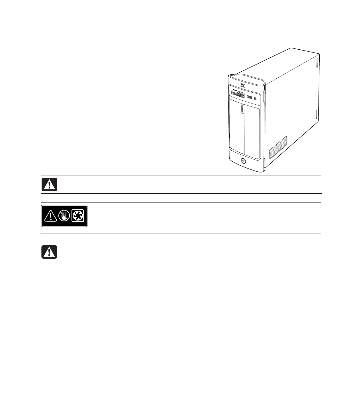
Introduction
W
The Upgrading and Servicing Guide provides instructions on how to
remove and replace the following hardware components in your
HP Pavilion Slimline Desktop PC:
• Optical disc drive
• Hard disk drive
• Memory module
• Modem card (PCI card)
• Battery
Safety Information
Please read the following important safety information before performing
any procedure.
This product has not been evaluated for connection to an “IT” power
system (an AC distribution system with no direct connection to earth,
according to IEC 60950).
WARNING: Please read “Safety Information” in your Warranty and Support Guide before
installing and connecting your system to the electrical power system.
ARNING: Keep your hands away from the moving fan. Keep fingers and tools clear
of the fan when power is applied. Never open the cover with the power cord
attached or power applied. You may damage your PC or be injured from the s
fan blades.
WARNING: Avoid touching sharp edges inside the PC.
pinning
Upgrading and Servicing Guide 1
Page 6
Opening the PC
W
Before you upgrade any component in your PC, prepare the PC so that you can safely handle the unit and the
components.
Read the following items before attempting to upgrade or service the PC:
• Print out this document before attempting any removal/replacement procedures.
• These procedures assume familiarity with the general terminology associated with PCs and with the safety
practices and regulatory compliance required for using and modifying electronic equipment.
• Write down and save the system model number and serial number, all installed options, and other information
about the system. If you need this information later, you will not need to open up and examine the PC.
CAUTION: Static electricity can damage the electronic components of the PC or optional
equipment. Ensure that you are discharged of static electricity by briefly touching a grounded
metal object.
• HP recommends that you use an antistatic wrist strap and a conductive foam pad when working on system
electronic components.
• You need a Phillips screwdriver.
Preparing the PC
To avoid injury and equipment damage, always follow this procedure in this order before opening the PC:
1 Remove any memory card from the memory card reader or an optical disc (CD or DVD) from the optical drive.
2 Turn off the PC:
a Click the Start button on the taskbar.
b Click Turn Off Computer, and then click Turn Off again.
3 Disconnect the modem/telephone cable, if present.
WARNING: Always disconnect the modem cord from the telephone system before opening the
cover.
4 Disconnect the power cord from the electrical outlet and then from the PC.
ARNING: To reduce the risk of personal injury from electrical shock or hot surfaces, disconnect
the power cord from the electrical outlet. Then disconnect the PC from the power source before
removing the PC cover. Failure to do so before you open the PC or do any procedures can result
in personal injury or equipment damage.
5 Disconnect all other attached cables (such as the keyboard, mouse, Ethernet, and monitor).
6 Disconnect all external devices.
2 Upgrading and Servicing Guide
Page 7
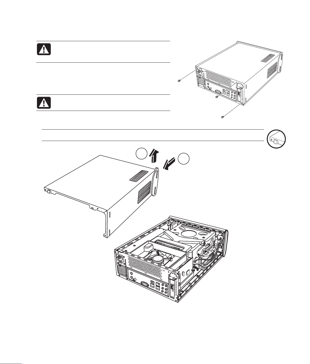
Removing the PC Cover
WARNING: Remove power before opening the
PC cover. Allow the internal system components
to cool before touching.
1 Complete the procedure “Preparing the PC” on page 2.
2 Lay the PC flat.
3 Loosen the three screws on the back cover. Use a Phillips
screwdriver.
WARNING: Avoid touching sharp edges inside
the PC.
4 Slide the PC cover back about 1.25 cm (1/2 inch) (A),
and then lift it off the PC (B). Set it aside.
NOTE: Use the screwdriver slot on the back of the cover to loosen the cover, as required.
B
A
Upgrading and Servicing Guide 3
Page 8
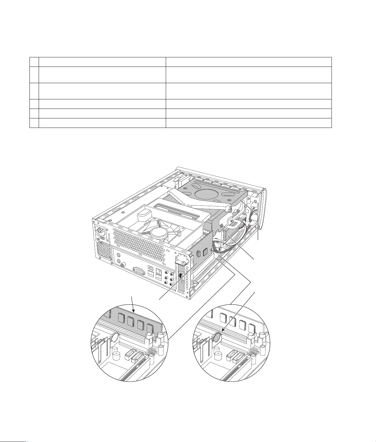
Locating Components Inside the PC
PC component configurations vary by model. You can remove and replace the following components:
Component See:
Optical disc drive. May be a CD-ROM, CD-RW,
A
DVD-ROM, DVD+RW, or combination drive.
Hard disk drive
B
(located under the optical drive bay).
C Memory module (2). “Removing and Replacing Memory” on page 13.
D Modem card (PCI card). “Removing and Replacing a PCI Card” on page 16.
E Battery. “Removing and Replacing the Battery” on page 18.
Read the “Before You Begin” section at the start of each component procedure. This section contains
requirements and important information about the replaceable component.
The following illustration shows component locations:
“Removing and Replacing an Optical Disc Drive” on page 6.
“Removing and Replacing a Hard Disk Drive” on page 10.
4 Upgrading and Servicing Guide
C
D
A
B
E
Page 9

Closing the PC
Replacing the PC Cover
1 Place all cables inside of the PC case.
2 Place the cover onto the PC (A) about 2.5 cm (1 inch)
back. Make sure the slots in the PC case align with the
cover tabs.
3 Slide the cover forward on the frame until it locks into
place (B). Make sure the bottom of the cover lines up with
the PC case.
4 Align the screws on the PC cover with the holes on the
back of the PC frame. Insert and then tighten the screws
on the cover (C).
5 Complete the procedure “After Closing the PC” on this
page.
After Closing the PC
To avoid injury and equipment damage, always follow this procedure in this order after closing the PC:
WARNING: To reduce the risk of electrical shock, fire, or damage to the equipment, do not plug
telecommunications or telephone connectors into the Ethernet network interface connector.
1 Reconnect the modem/telephone cable and all other attached cables, such as the keyboard, mouse, Ethernet,
and monitor cables.
2 Reconnect external devices, such as a printer.
3 Reconnect the power cord.
4 Turn on the PC and all peripherals, such as the monitor.
Upgrading and Servicing Guide 5
Page 10
Removing and Replacing an Optical Disc Drive
Your PC includes an optical disc drive that you can replace or upgrade. See “Locating Components Inside the
PC” on page
Before You Begin
Observe the following requirements before removing and
replacing the component:
IMPORTANT: Due to the small PC size, you can only
install an optical disc drive of less than the approximate
length of 170 mm (
The optical disc drive may be either a PATA (parallel
advanced technology attachment) drive or SATA (serial
advanced technology attachment) drive that uses a
narrow data cable with an optional latch.
4.
6.7 inches).
This procedure requires a Phillips screwdriver.
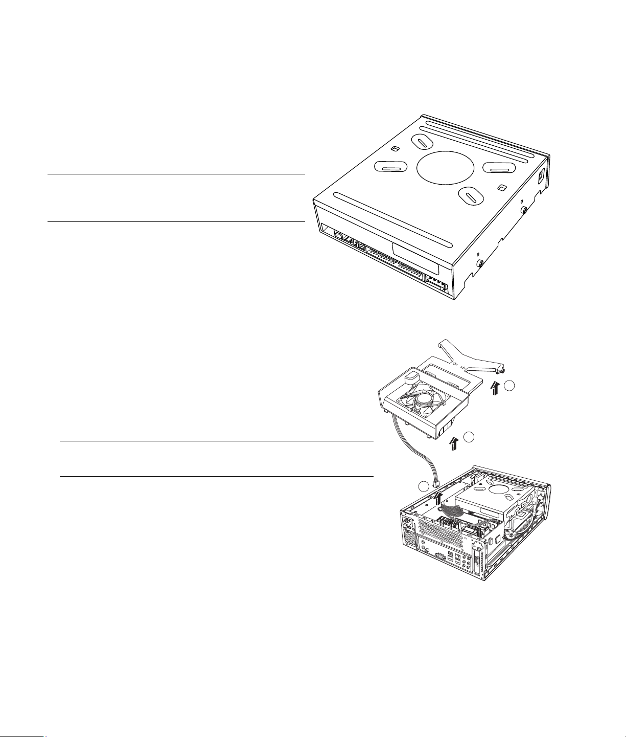
Removing an Optical Disc Drive
1 Prepare the PC and remove the PC cover. Complete the “Opening the
PC” procedures on page
2 Remove the fan assembly:
a Lift the fan assembly upward at the arrows shown (A).
b Lift out the fan assembly (B).
c Disconnect the fan power cable by grasping the connector and
pulling up (C).
IMPORTANT: Make a note of the fan power cable routing before
removing the cable.
3 Make a note of each cable and plug orientation attached to the back
of the optical disc drive before removing the cables.
2.
Optical disc drive
A
B
C
6 Upgrading and Servicing Guide
Page 11

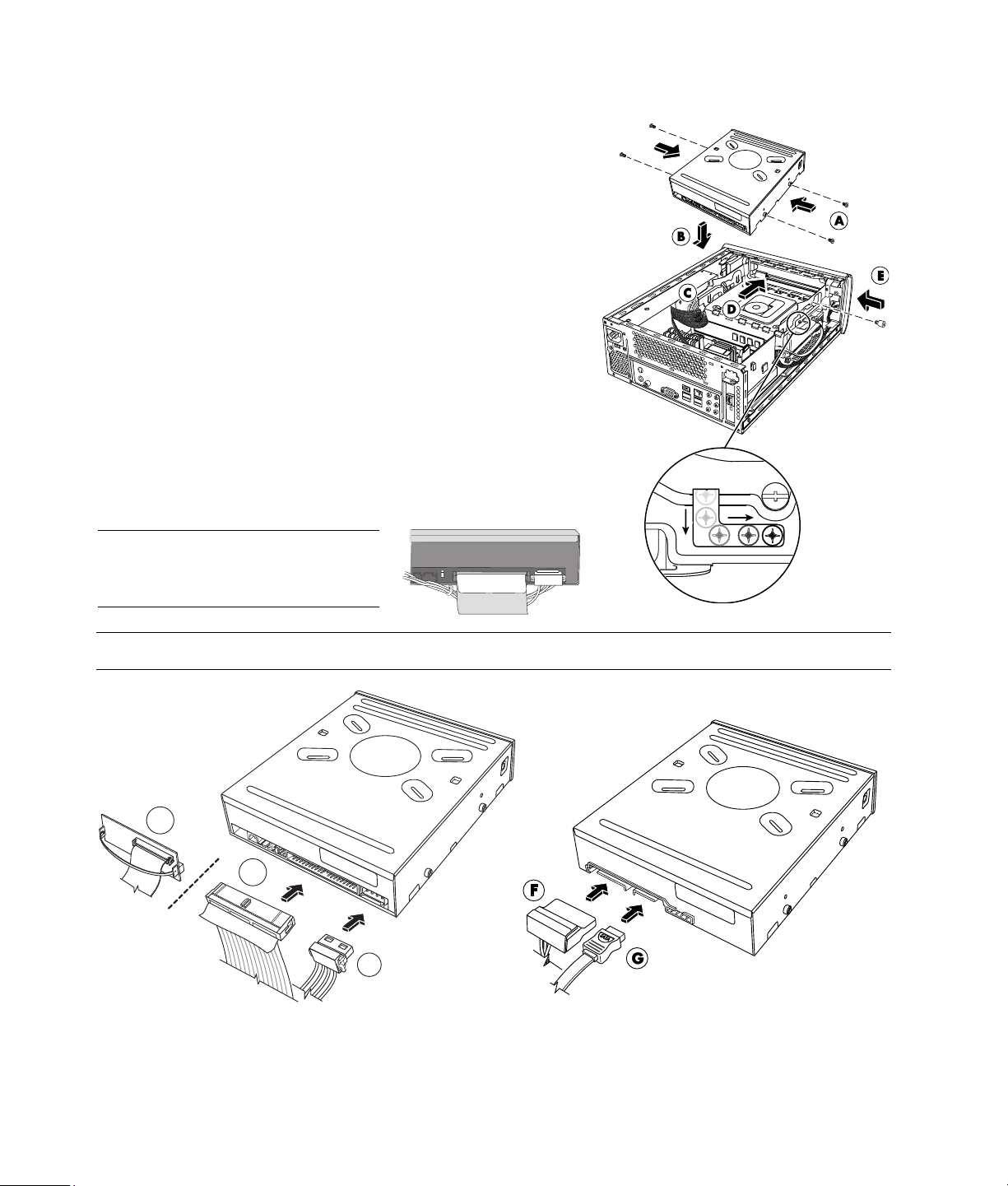
4 Disconnect the power cable (A) and then the data cable (B) from the back of the optical disc drive. Pull the tab
C
E
G
D
F
on the data cable. Use a gentle rocking motion on the power cable.
B1
B2
A
A
B
PATA optical disc drive — remove (A) and (B1) or (B2) SATA optical disc drive
NOTE: The PATA data cable may be a thin ribbon cable
(B1) or a thicker ribbon cable (B2). The thin ribbon
cable is attached to a connector. Do not disconnect the
NOTE: The SATA data cable may include a latch.
Press the latch and pull the plug to remove the data
cable from the drive.
thin ribbon cable from the connector.
CAUTION: Pull the connector by the handle only.
5 Disconnect the sound cable, if present.
6 Remove the thumbscrew (C) from the optical disc drive side.
7 Hold back the power supply cables to clear the optical disc
drive (D), and slide the drive 2 cm (3/4 inch) toward the back of
the PC (E).
8 Lift the drive straight up out of the PC (F).
IMPORTANT: Do not tilt the drive during removal.
9 Remove the four guide screws from the sides of the old drive (G).
You need these screws to install the new drive.
Upgrading and Servicing Guide 7
Page 12
Replacing an Optical Disc Drive
1 Complete the procedure “Removing an Optical Disc Drive“ on
6.
page
2 Screw all four guide screws into the sides of the new optical disc
drive (A).
3 Gently lower the new optical disc drive into the tray (B).
4 Hold the power supply cables against the power supply to clear the
optical disc drive (C) (as required) and slide the drive 2 cm
(3/4 inch) to the front of the PC (D).
5 Insert the thumbscrew on the side of the optical disc drive (E).
6 Connect the power cable (F) and data cable (G) firmly to the back of
the optical disc drive. Ensure that the cables are completely inserted.
The optical drive model may have PATA cables or SATA cables that
use narrow data cables.
• SATA cables may include a latch.
• The PATA data cable may be a thin ribbon cable (G1) or a thicker
ribbon cable (G2). The thin ribbon cable is attached to a
connector with a pull handle.
NOTE: Route the PATA power cable
under the data cable to prevent
interference with the fan.
CAUTION: Do not disconnect the PATA thin ribbon cable from the data cable connector.
G1
G2
F
PATA optical disc drive — attach (F) and (G1) or (G2) SATA optical disc drive
8 Upgrading and Servicing Guide
Page 13
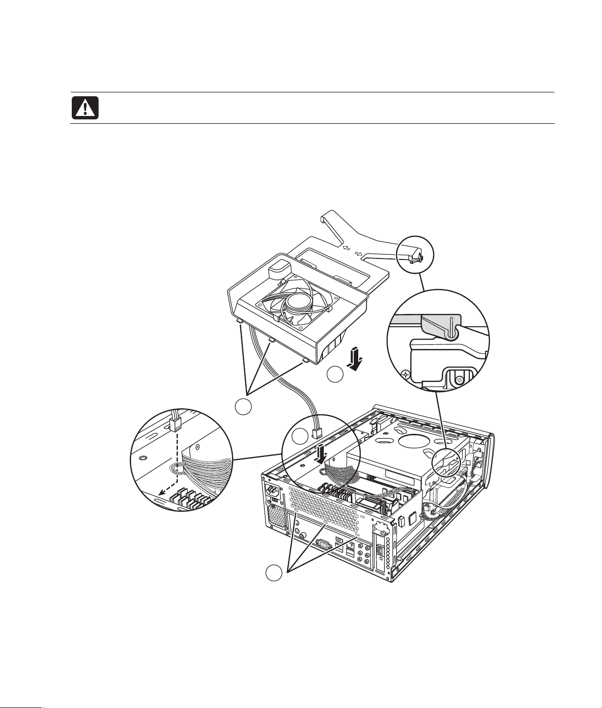
7 Some drive models may have a sound cable. If so, connect the sound cable.
8 Replace the fan assembly:
WARNING: Route the fan power cable around the power supply cable lines, exactly as
removed, to prevent the fan power cable from contacting fan blades.
a Connect the fan power cable (A). Route the fan power cable through the wire loop.
b Lower the fan assembly into place (B).
c Slide the fan assembly back (C). Set the three tabs on the fan assembly into the three slots in the back
panel. Snap the two posts on the fan assembly into the two receptacles on the drive tray.
9 Replace the PC cover and close the PC. Complete the “Closing the PC” procedures on page
5.
B
C
A
C
Upgrading and Servicing Guide 9
Page 14
Removing and Replacing a Hard Disk Drive
Your PC includes a hard drive that you can replace or
upgrade. See “Locating Components Inside the PC” on
4.
page
The original hard disk drive is preloaded with the PC system
recovery partition. If you remove this hard disk drive, store it
in a properly sealed antistatic bag.
The hard disk drive is a SATA (serial advanced technology
attachment) drive that uses a narrow data cable with an
optional latch.
Before You Begin
Observe the following requirements before removing and
replacing the component:
CAUTION: Before you remove the hard disk drive, back up your personal files on the hard disk
drive to an external storage device, such as a DVD, CD, or USB drive. Failure to do so will result
in data loss.
After you replace the hard disk drive, perform the System Recovery procedure. Use the recovery
discs to load the factory-installed files. Refer to the PC Troubleshooting Guide for detailed
System Recovery steps.
Hard disk drive
IMPORTANT: Before upgrading a hard disk drive, make sure a recovery disc is available.
This procedure requires a Phillips screwdriver.
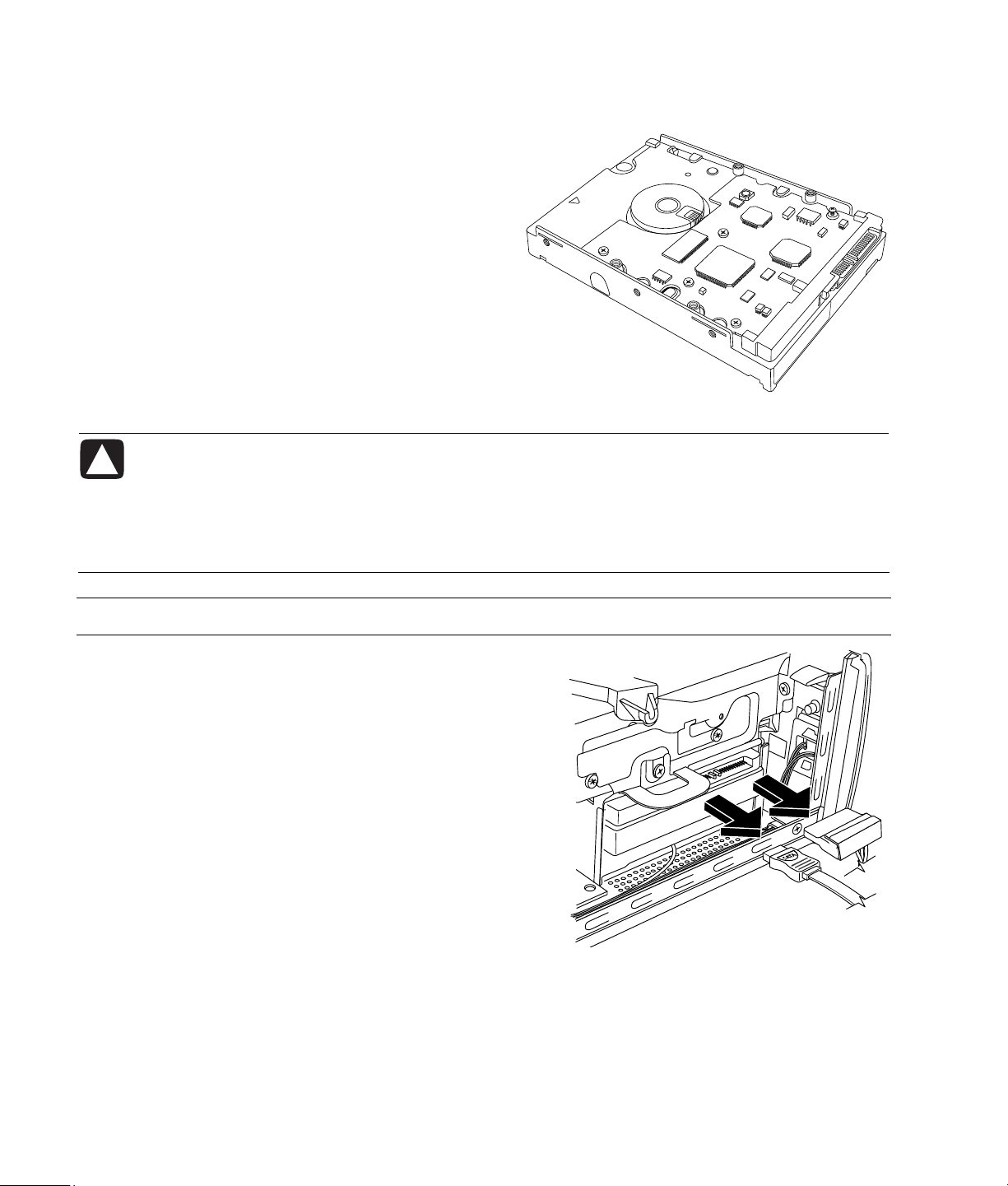
Removing a Hard Disk Drive
1 Prepare the PC and remove the PC cover. Complete the
“Opening the PC“ procedures on page
2 Make a note of each cable attached to the hard disk drive
before removing the cables.
3 Disconnect the power and data cables from the back of the
hard disk drive.
2.
10 Upgrading and Servicing Guide
Page 15

NOTE: SATA data cables may include a latch (underneath
the plug for select models only). Press the latch and pull the
plug to remove the data cable from the drive.
4 Remove the retaining screw from the drive tray.
CAUTION: Handle hard disk drives with care.
Dropping or banging the hard disk drive can
result in data loss.
5 Slide the hard disk drive tray out of the drive bay by
pulling the tab on the drive tray.
NOTE: Ensure that the PC cables are clear of the drive tray
when removing. Push them away, as required, before
removing the tray.
6 Remove the four screws that secure the hard disk drive to
the drive tray (A) and slide out the hard disk drive out of
the tray (B).
Upgrading and Servicing Guide 11
Page 16

Replacing a Hard Disk Drive
1 Complete the “Removing a Hard Disk Drive” procedure on
10.
page
2 Slide the hard disk drive into the tray (A).
3 Insert and tighten the four screws that secure the hard disk
drive to the drive tray (B).
4 Slide the hard disk drive tray into the PC drive bay.
5 Insert and tighten the hard disk drive retaining screw into the drive tray.
12 Upgrading and Servicing Guide
Page 17
6 Attach the data and power supply cables to the back of the
hard disk drive.
7 Complete the procedures to replace the PC cover and close
the PC. See “Closing the PC” on page
5.
8 Perform a System Recovery, as required. Use the recovery
discs to replace the factory-installed files. Refer to the PC
Troubleshooting Guide for detailed System Recovery
procedures.
Removing and Replacing Memory
The motherboard contains one or two memory module sockets for DDR DIMMs (double data rate dual in-line
memory modules).
Before You Begin
Observe the following requirements before removing and replacing
the component:
To determine which type and speed of memory module your
PC uses, and for specific memory module information and
specifications:
1 Go to http://www.hp.com/support in your Web browser.
2 Select your country/region and language.
3 From the Support and Drivers page, click See support and
troubleshooting information, enter the model number of
your PC, and then click Search.
WARNING: Using the wrong type of memory module could damage the system.
WARNING: Handle the memory module with care. Be careful to not touch any memory module
contacts. Touching the gold contacts may damage the module. Avoid touching the memory
chips.
Memory module
Upgrading and Servicing Guide 13
Page 18

Removing a Memory Module
1 Remove the optical disc drive. See “Removing an Optical Disc Drive” on page 6.
2 Locate the memory socket on the motherboard.
3 Move any cabling out of the way, if necessary.
WARNING: Do not pull the memory module out of the socket. Use the retaining clips to eject the
module.
4 Push down the two retaining clips on the ends of the socket until the memory module pops out of the socket.
Hold the memory module by its edges only, as you lift it away from the socket.
5 Store the memory module in antistatic packaging.
14 Upgrading and Servicing Guide
Page 19

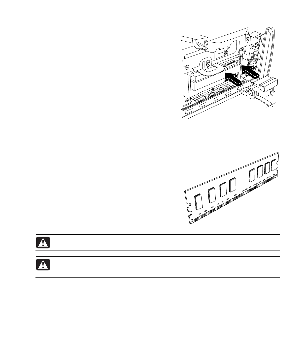
Replacing a Memory Module
Upgrade the memory in your PC with memory of the same type and speed as the memory originally installed in
your PC.
1 Complete the procedure in “Removing a Memory Module” on page
14.
2 Open both latches of the memory module socket.
WARNING: Handle the memory module with care. Be careful to not touch any memory module
contacts. Touching the gold contacts may damage the module. Avoid touching the memory
chips.
3 Remove the new memory module from the antistatic packaging. Hold it by its edges only.
4 You can install the memory module in only one position. Match the notch (A) on the memory module with the
tab (B) on the memory socket. Push the module carefully and firmly into the slot, ensuring that the latches on
both ends snap into place.
5 Repeat steps 1 to 4 for the second memory slot, as required.
6 Replace any cabling that was moved.
7 Complete the procedures to replace the optical disc drive. See “Replacing an Optical Disc Drive” on page
Upgrading and Servicing Guide 15
8.
Page 20

Removing and Replacing a PCI Card
You can also replace the modem card in the PCI card slot with another
modem card or a new PCI card. The modem card is a telephone modem
circuit board that fits into a PCI card slot.
Before You Begin
Observe the following requirements before removing and replacing the
component:
IMPORTANT: Due to the small PC size, you can only install a small,
low-profile PCI card of the same approximate size of the modem card.
HP recommends that you install a card with power consumption of
5 watts or less.
Not all low-profile cards will fit into the PCI slot. Some external
connectors, especially connectors located at the top of the card, may not
fit properly into the back panel.
This procedure requires a Phillips screwdriver.
Removing a PCI Card
1 Prepare the PC and remove the PC cover. Complete the “Opening the PC”
procedures on page
2 Inside the PC, locate the PCI card slot on the motherboard.
3 Make a note of any internal cables attached to the card, and then
disconnect them.
4 Remove the screw on the modem card bracket holder (A) on the outside of
the frame. Remove the bracket holder.
5 Hold the card at the top and carefully pull the card straight out of the
slot (B).
2.
PCI card
16 Upgrading and Servicing Guide
Page 21

Replacing a PCI Card
You can replace the modem card with a new modem card or another PCI
card in the PCI card slot:
1 Complete the procedures to remove the modem card. See “Removing
a PCI Card” on page
2 Align the edge of the add-in card with the slot on the PC and gently
but firmly press the card straight down into the card slot (A). The whole
connector should be seated properly in the card slot.
3 Attach the bracket holder with the screw to secure the card (B).
16.
4 Connect any internal cables attached to the card.
5 Complete the procedures to close the PC. See “Closing the PC” on page 5.
6 Install any software drivers— supplied by the card manufacturer if you are installing another PCI card— or as
required.
NOTE: If the new card or device isn’t working, read the card manufacturer’s installation instructions, and recheck
all connections, including those to the card, power supply, keyboard, and monitor.
Upgrading and Servicing Guide 17
Page 22

Removing and Replacing the Battery
A lithium battery on the motherboard provides backup power for the PC’s timekeeping capability.
When the battery starts to weaken, the date and time may be incorrect. If the battery fails, replace it with a
CR2032 lithium battery (3-volt, 220 mAh rating) or an equivalent battery.
Before You Begin
Observe the following requirements before removing and replacing the component:
WARNING: There is danger of explosion if the battery is incorrectly replaced. Replace only with
the same, or equivalent, type of battery. Discard used batteries according to the manufacturer’s
instructions.
WARNING: Never use metal, such as pliers, to remove or replace the battery. Metal contact may
cause a battery short and damage the battery.
Procedure
1 Prepare the PC and remove the PC cover. Complete the “Opening the PC” procedure on page 2.
2 Gently lay the PC on its side.
3 Complete the procedure “Removing an Optical Disc Drive” on page
4 Remove any cabling, if necessary, to reach the battery.
5 Move the retaining clip away from the battery. Lift the battery from the socket to release the battery.
6.
6 Install the new CR2032 battery in the socket, with the positive (+) side facing the open side of the socket.
7 Replace all cables that you removed.
8 Complete the procedure “Replacing an Optical Disc Drive” on page
9 Complete the procedures to replace the PC cover and close the PC. See “Closing the PC” on page
NOTE: You may have to manually set the time and date on the PC after startup.
8.
5.
18 Upgrading and Servicing Guide
Page 23

Page 24

Part number: 5991-7191
 Loading...