

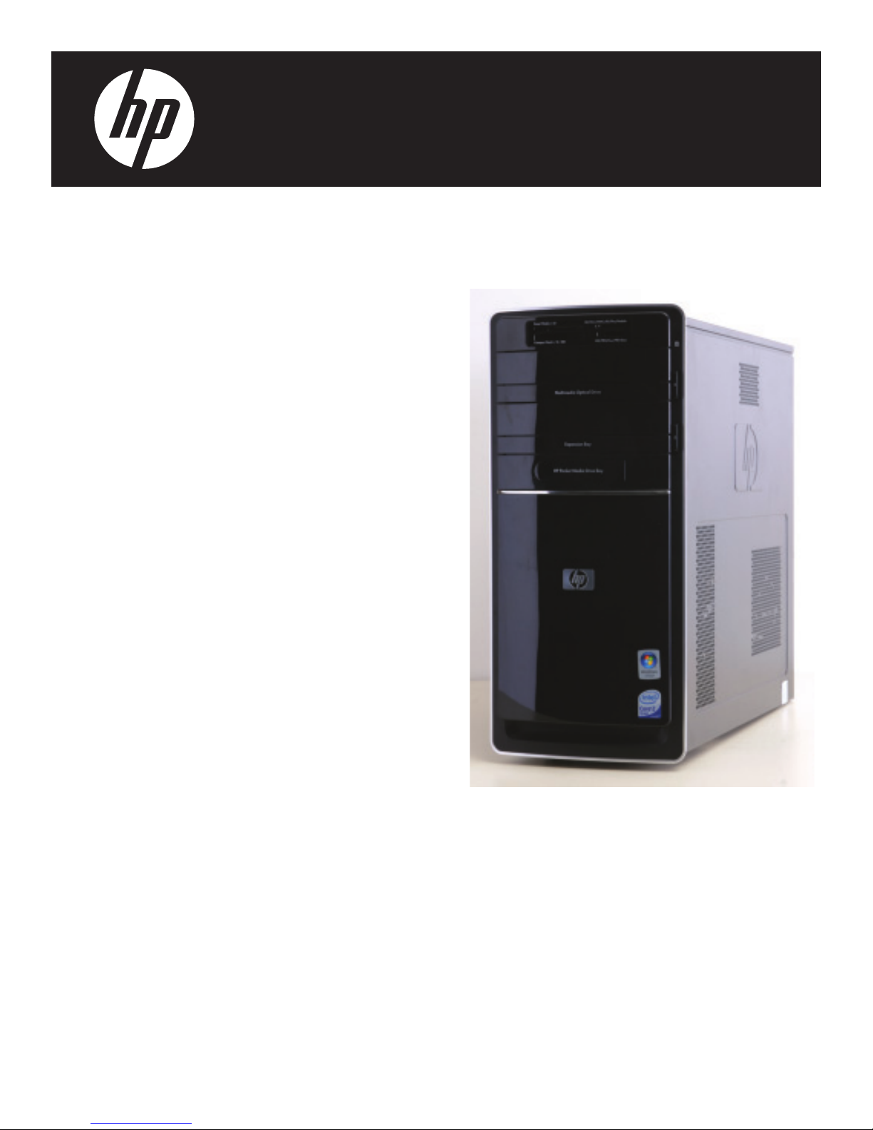
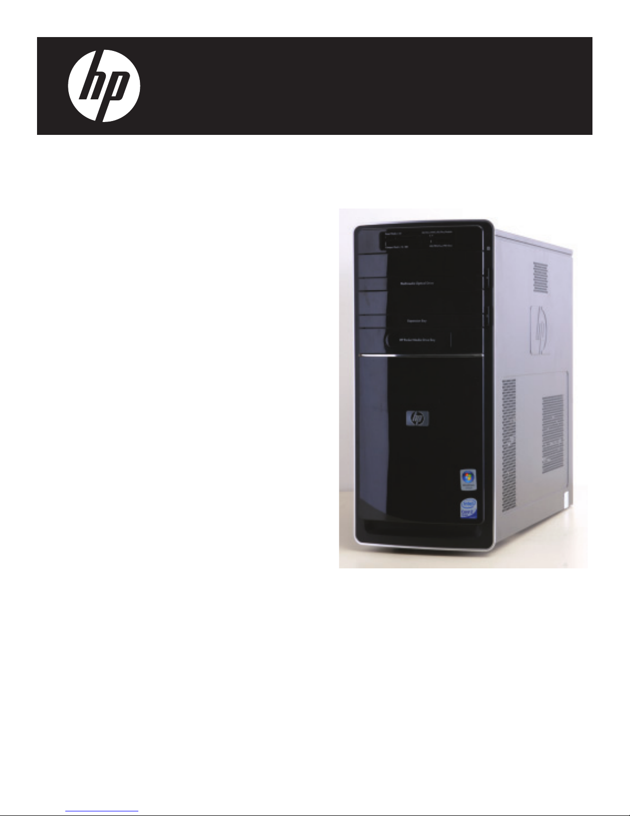
HP Pavilion p6400, Pavilion p6500, Pavilion p6600, Pavilion p6700, Pavilion p6800 Supplementary Manual
...Page 1
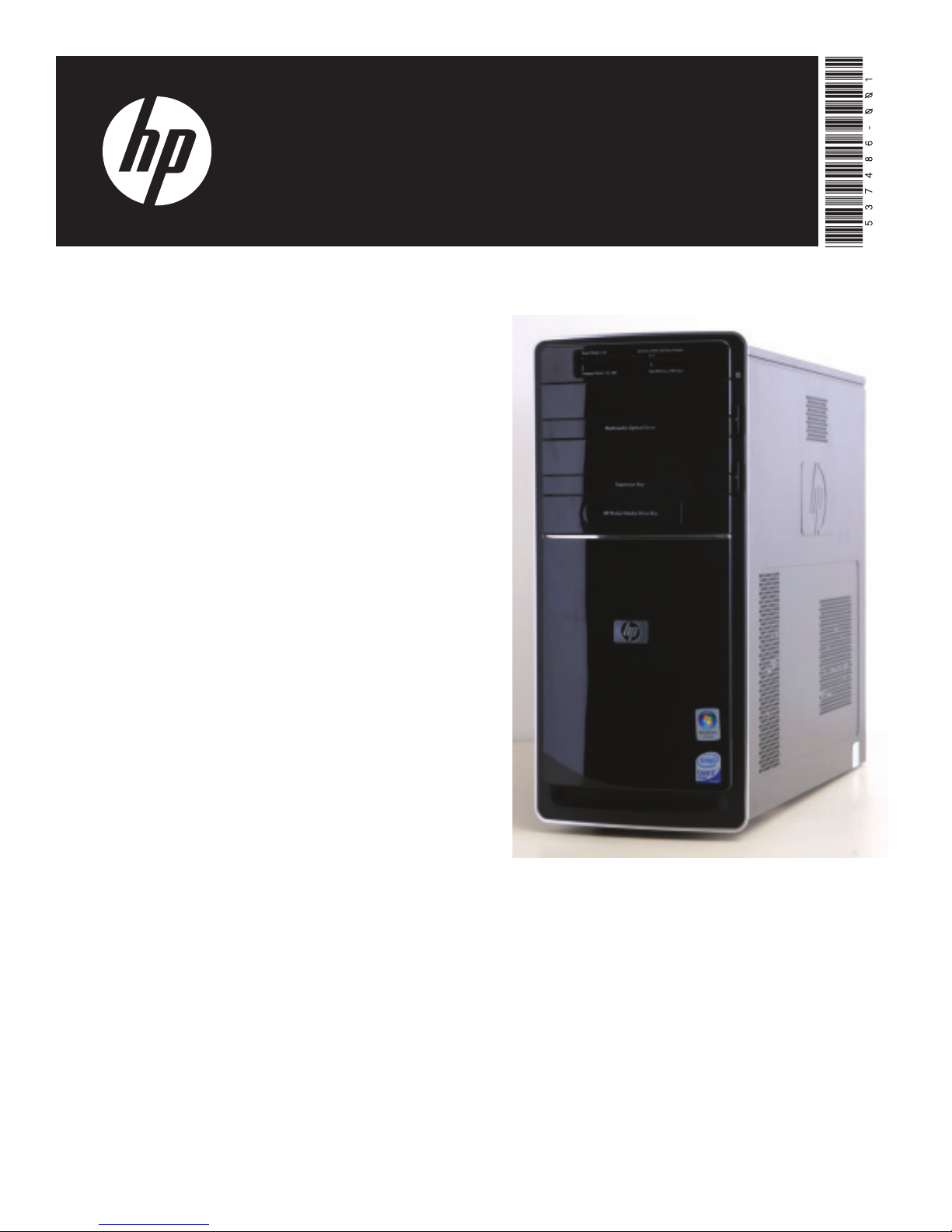
Upgrading and Servicing Guide
Printed in
Page 2

Page 3
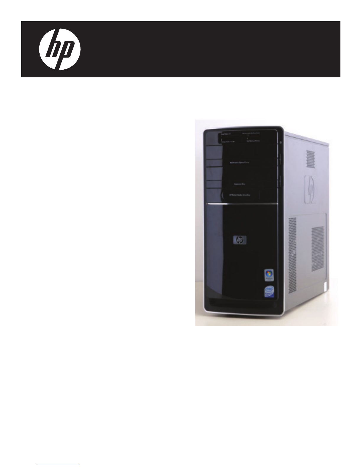
Removing and Replacing the
Front Panel
Page 4
Removing and Replacing the Front Panel
10–20 minutes
Before You Begin
Observe the following requirements before removing and
replacing the front panel.
Tools Needed
Flathead screwdriver
You can use a flathead screwdriver with the
following screw (torque screw).
CAUTION: Static electricity can damage
the electronic components inside the
computer. Discharge static electricity by
touching the metal cage of the computer
before touching any internal parts or
electronic components.
WARNING:
Removing the Front Panel
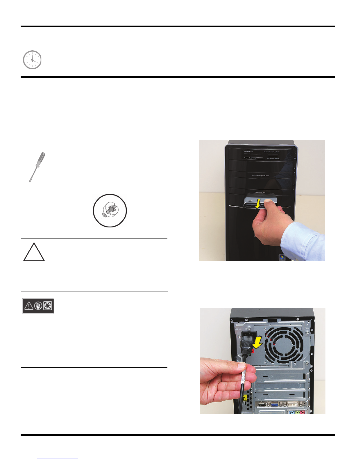
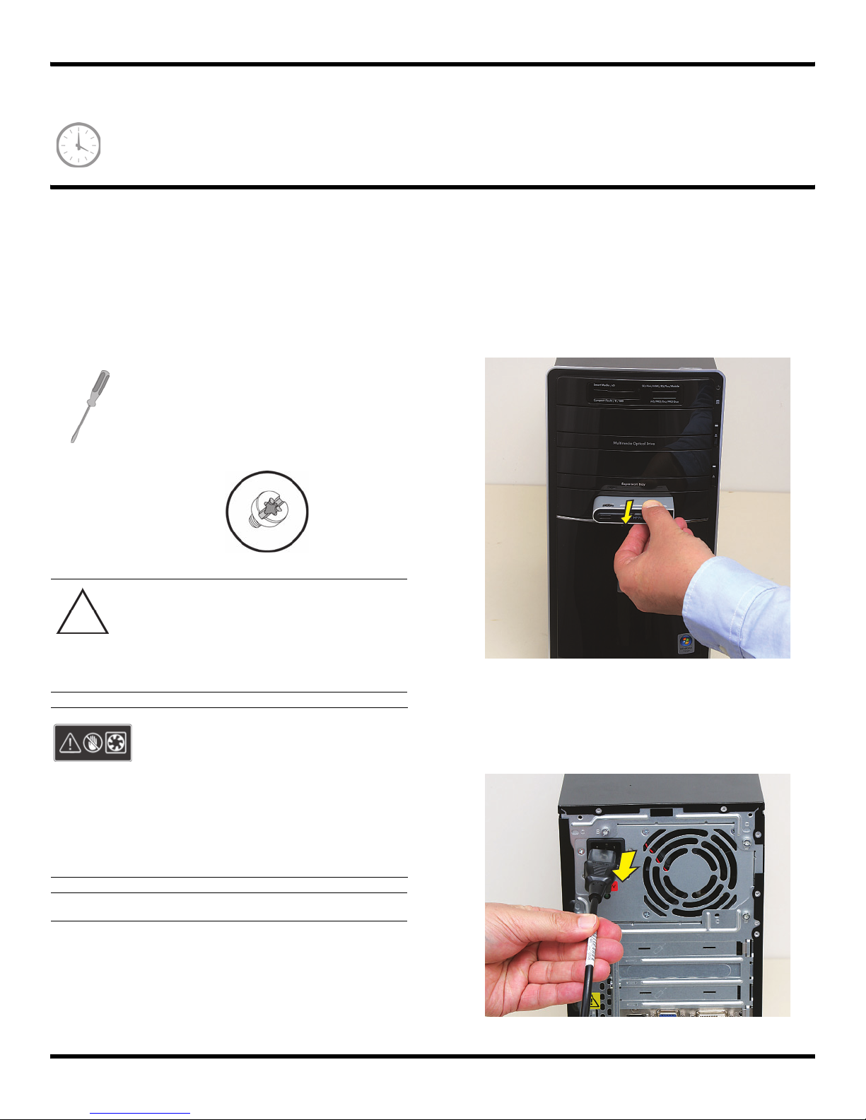
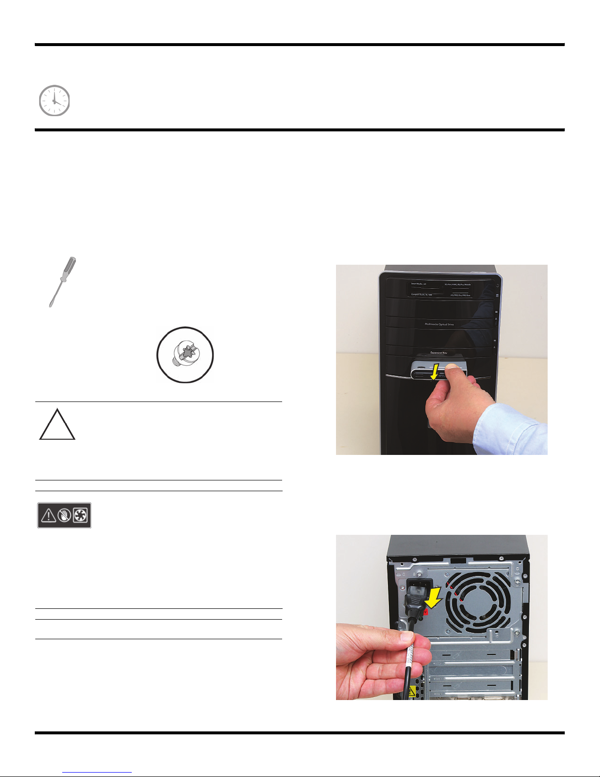
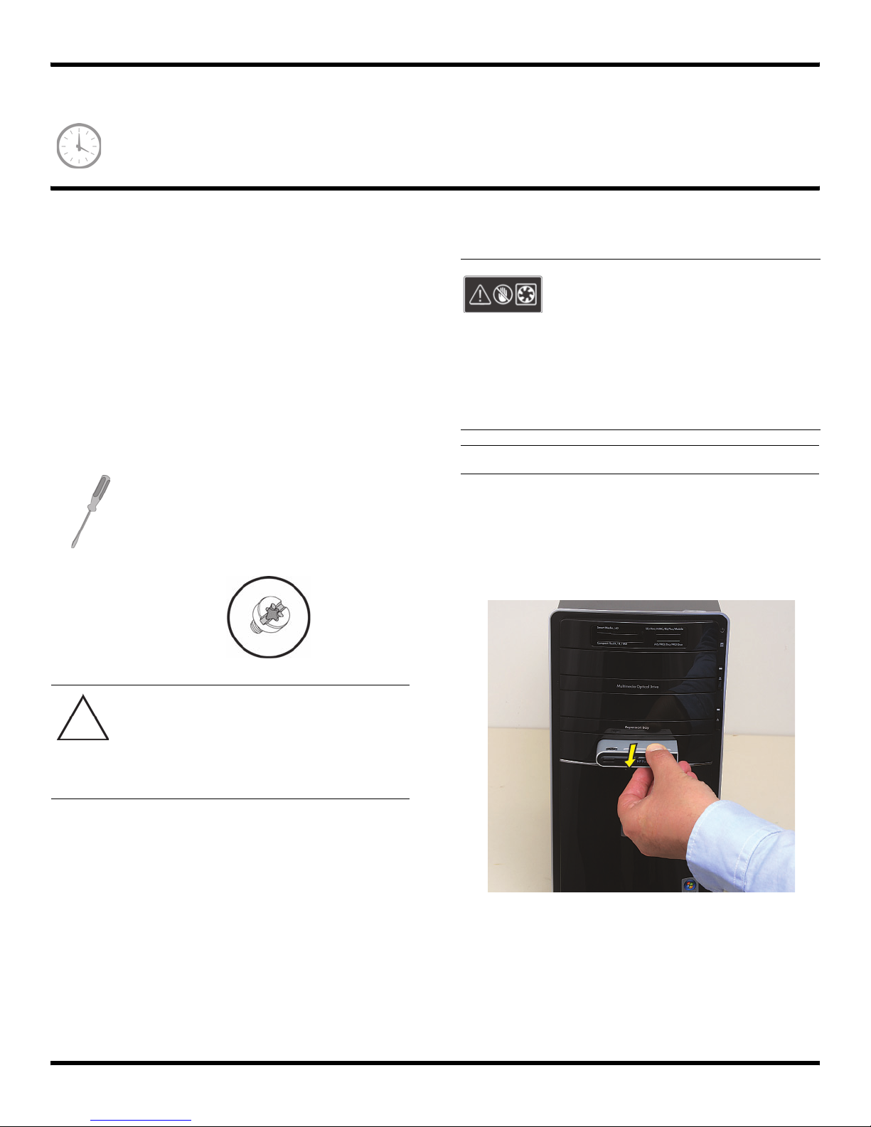
1 Remove the Pocket Media Drive, if it is present.
2 Turn off the computer.
3 Disconnect all peripherals and cables from the front
and the back of the computer. Disconnect the power
cord last.
Never open the cover with the
power cord attached or power
applied. You may damage your
computer or be injured from the
spinning fan blades.
Avoid touching sharp edges
inside the computer.
NOTE: Computer features may vary by model.
2 570981-001 — Removing and Replacing the Front Panel
Page 5
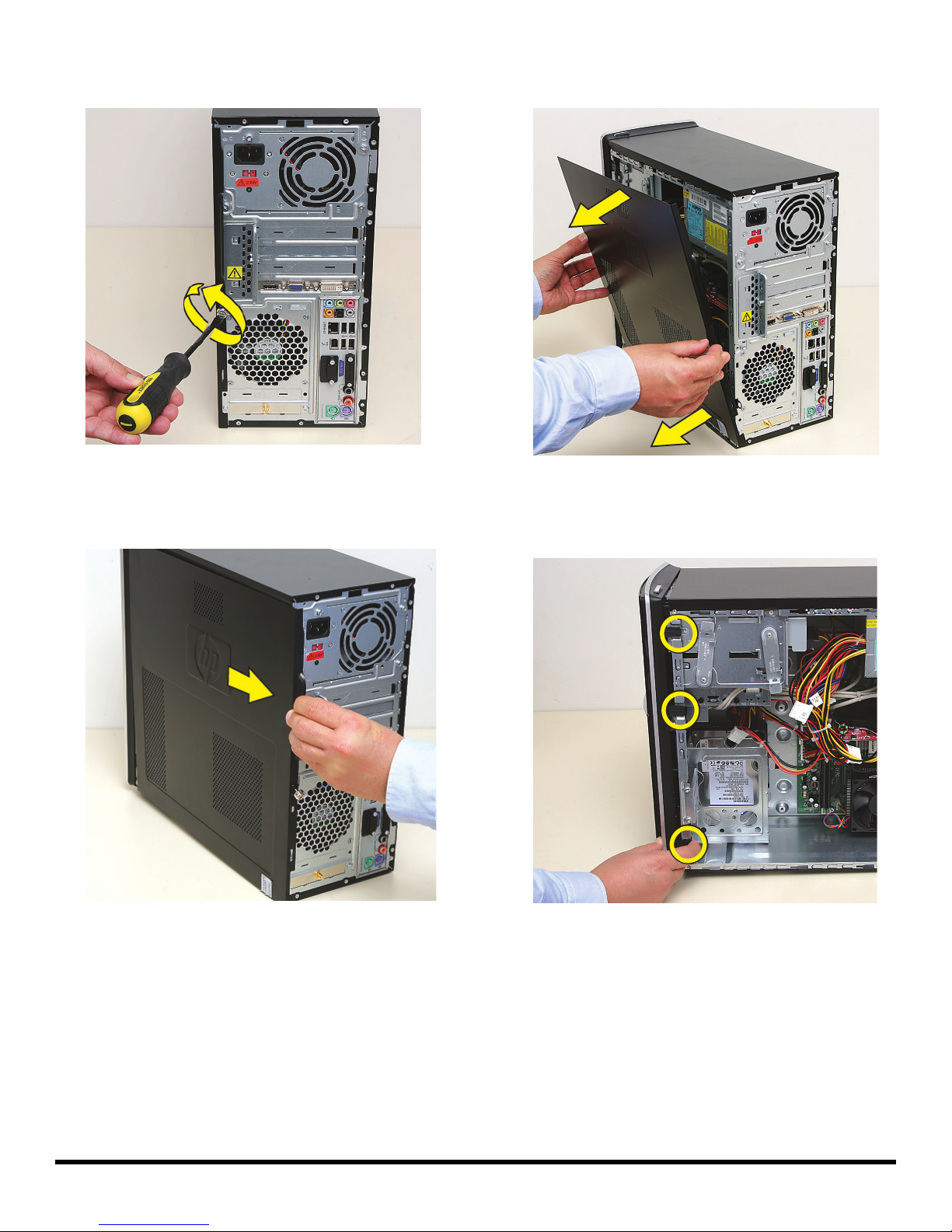
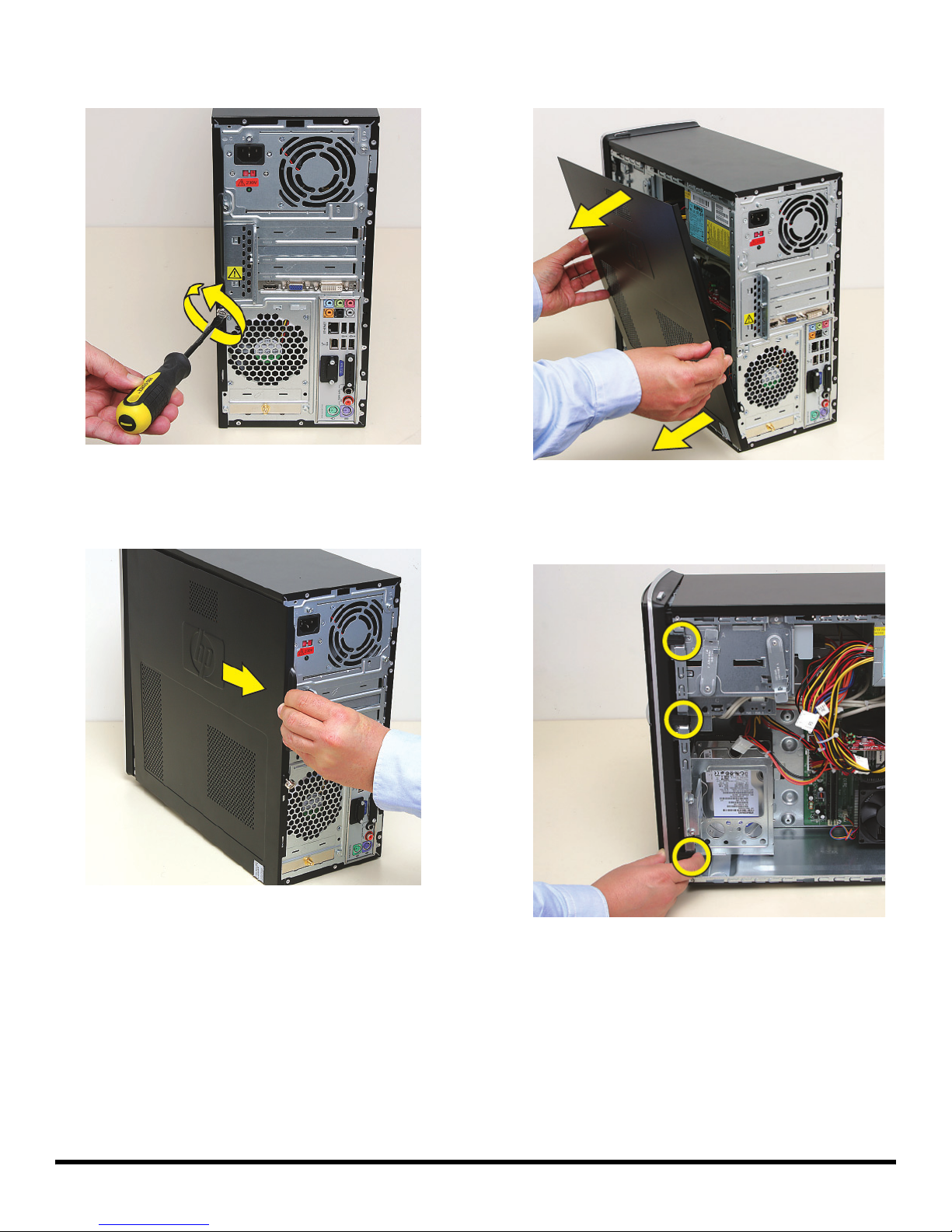
4 Loosen the side panel thumbscrew on the back of the
computer.
6 Tilt out the top of the side panel, and then lift the panel
from the computer.
--
5 Grasp the handle, and pull the side panel about
2.5 cm (1 inch) toward the back of the computer to
release it.
7 Locate the three tabs that secure the front panel to the
computer. Pull each of the tabs out slightly, away from
the computer, to release the panel.
570981-001 — Removing and Replacing the Front Panel 3
Page 6
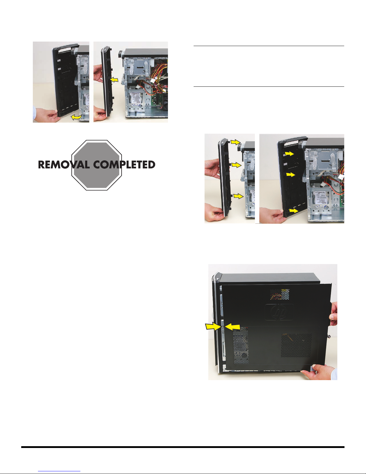
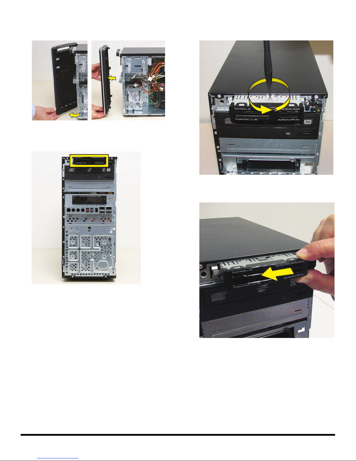
8 Swing the front panel open toward the left, and then
lift it off the computer.
Replacing the Front Panel
IMPORTANT: The new (replacement) part may not look
the same as the original part, due to different
manufacturers or models. Hewlett-Packard always
provides quality parts that meet or exceed your original
computer specifications.
1 Hold the front panel over the front of the computer,
and then press the left side of the front panel, inserting
the tabs into the computer holes. Swing the right side
of the panel toward the computer, inserting the panel
tabs, and then press it into the computer.
2 Hold the side panel over the side of the computer with
the front edge of the panel about 2.5 cm (1 inch) from
the front of the computer.
4 570981-001 — Removing and Replacing the Front Panel
Page 7
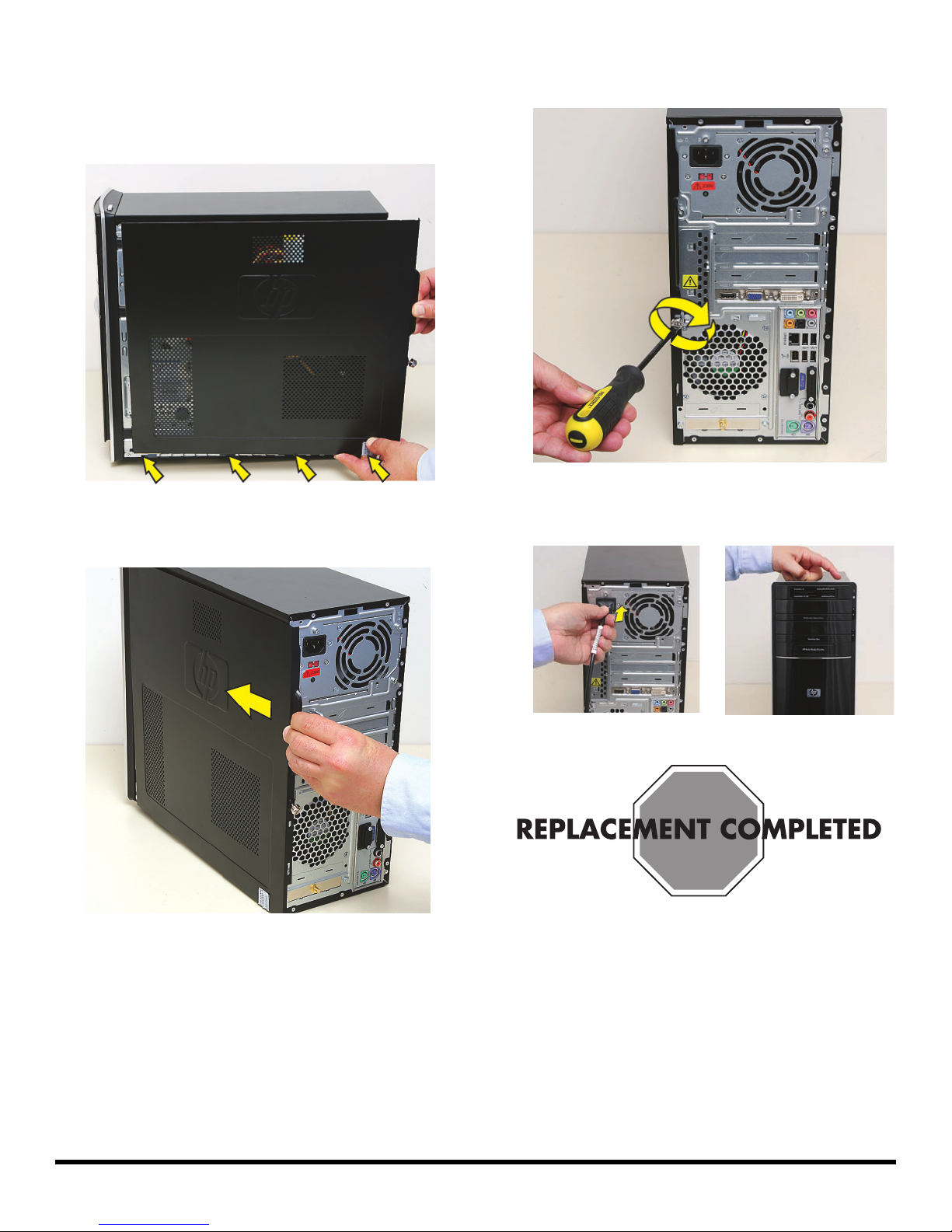
3 Place the bottom of the panel on the computer,
inserting the tabs on the inside of the panel into the
rail slots on the computer. Swing the top of the panel
toward the computer, inserting the top tabs into the
rail slots.
4 Slide the side panel toward the front of the computer
and into place.
5 Tighten the side panel thumbscrew on the back of the
computer.
6 Reconnect all peripherals and cables, and then turn
on the computer.
570981-001 — Removing and Replacing the Front Panel 5
Page 8

6 570981-001 — Removing and Replacing the Front Panel
Page 9
Removing and Replacing an
Optical Disc Drive
Page 10
Removing and Replacing an Optical Disc Drive
15–25 minutes
Before You Begin
Observe the following requirements before removing and
replacing the optical disc drive.
Tools Needed
Flathead screwdriver
You can use a flathead screwdriver with the
following screw (torque screw).
CAUTION: Static electricity can damage
the electronic components inside the
computer. Discharge static electricity by
touching the metal cage of the computer
before touching any internal parts or
electronic components.
Removing an Optical Disc Drive
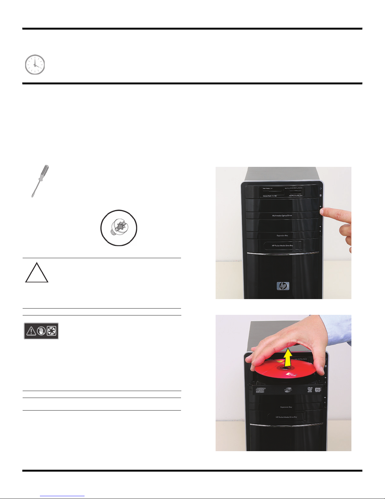
1 Before you begin servicing the computer, press the
Eject button, and remove any CD or DVD from the
optical disc drive tray.
WARNING:
Never open the cover with the
power cord attached or power
applied. You may damage your
computer or be injured from the
spinning fan blades.
Avoid touching sharp edges
inside the computer.
NOTE: Computer features may vary by model.
2 537487-001 — Removing and Replacing an Optical Disc Drive
Page 11
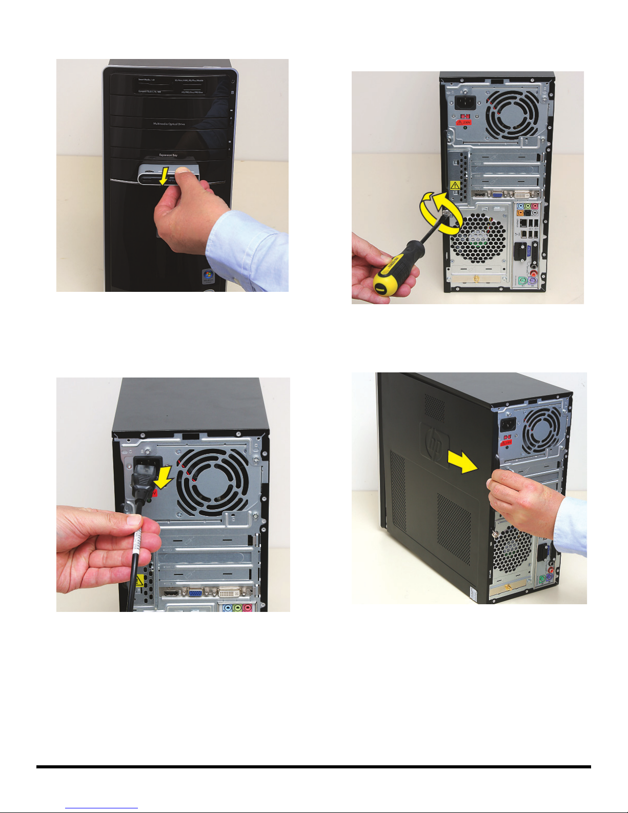
2 Remove the Pocket Media Drive, if it is present.
3 Turn off the computer.
4 Disconnect all peripherals and cables from the front
and the back of the computer. Disconnect the power
cord last.
5 Loosen the side panel thumbscrew on the back of the
computer.
6 Grasp the handle, and pull the side panel about
2.5 cm (1 inch) toward the back of the computer to
release it.
537487-001 — Removing and Replacing an Optical Disc Drive 3
Page 12
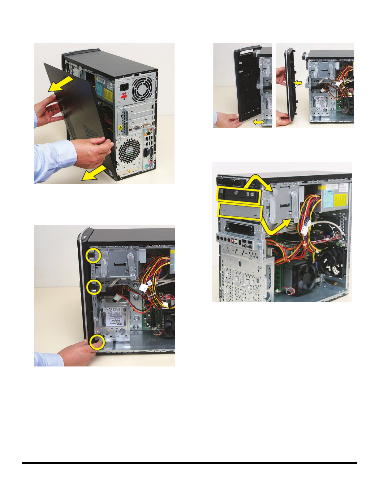
7 Tilt out the top of the side panel, and then lift the panel
from the computer.
--
8 Locate the three tabs that secure the front panel to the
computer. Pull each of the tabs out slightly, away from
the computer, to release the panel.
9 Swing the front panel open toward the left, and then
lift it off the computer.
10 Locate the optical disc drive you want to replace (and
also the drive latch for it).
4 537487-001 — Removing and Replacing an Optical Disc Drive
Page 13
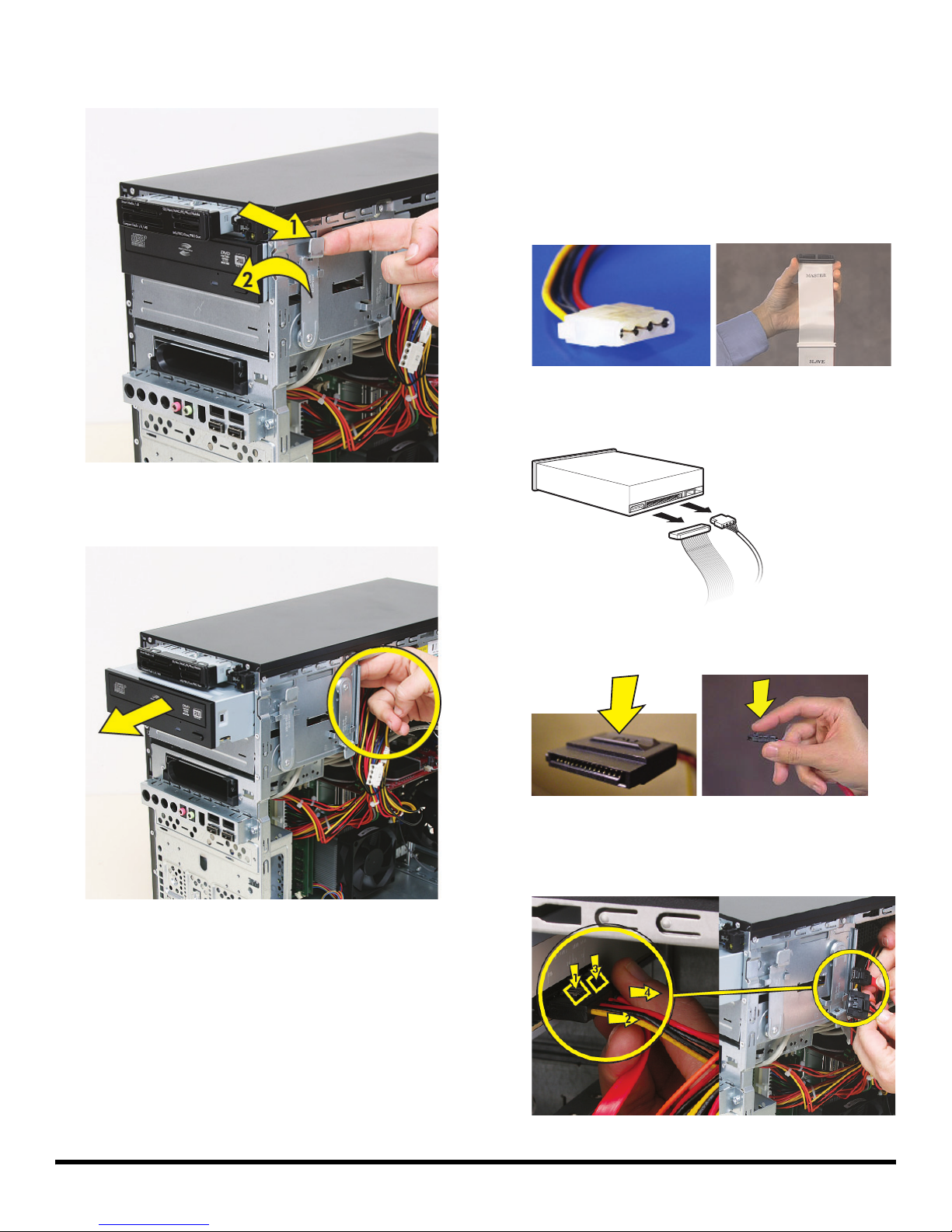
11 Pull out the optical drive latch (1), and then swing it to
the left until it is in the center position (2).
12 Push the drive partway out through the front of the
computer.
13 Disconnect the cables from the drive:
The plugs on the cables are keyed and can be
inserted only when aligned properly with the
connector on the drive.
In addition, some plugs have a latch that must be
pressed or squeezed to release the plug while pulling
it from the connector.
Plugs without a latch:
For plugs without a latch, pull the plug straight out
from the connector.
Plugs with a latch:
For plugs with a latch, press the latch (1 or 3) in the
center of each plug, and then pull the plug (2 or 4)
from the connector.
537487-001 — Removing and Replacing an Optical Disc Drive 5
Page 14
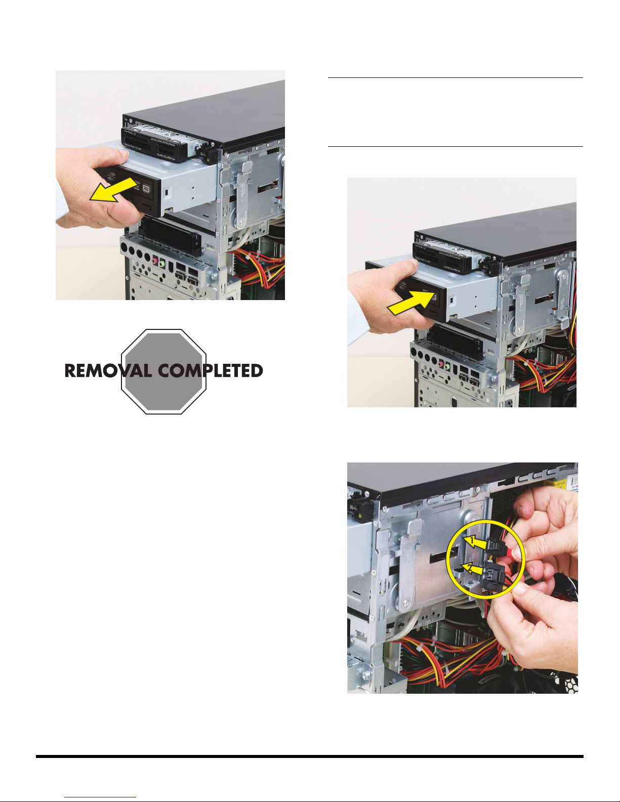
14 Pull the drive completely out through the front of the
computer.
Replacing an Optical Disc Drive
IMPORTANT: The new (replacement) part may not look
the same as the original part, due to different
manufacturers or models. Hewlett-Packard always
provides quality parts that meet or exceed your original
computer specifications.
1 Insert the drive partway into the computer bay.
2 Connect the data (1) and power (2) cables to the
back of the drive.
6 537487-001 — Removing and Replacing an Optical Disc Drive
Page 15
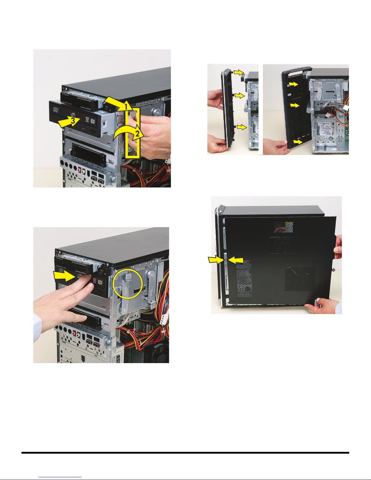
3 Pull out the optical drive latch (1), swing it to the
right (2), and release it into the hole labeled 2 on the
computer; then, push in the drive (3).
5 Hold the front panel over the front of the computer,
and then press the left side of the front panel, inserting
the tabs into the computer holes. Swing the right side
of the panel toward the computer, inserting the panel
tabs, and then press it into the computer.
6 Hold the side panel over the side of the computer with
the front edge of the panel about 2.5 cm (1 inch) from
the front of the computer.
4 Push the drive completely into the computer, until the
optical drive latch locks it into place in the hole
labeled 2 on the computer.
537487-001 — Removing and Replacing an Optical Disc Drive 7
Page 16
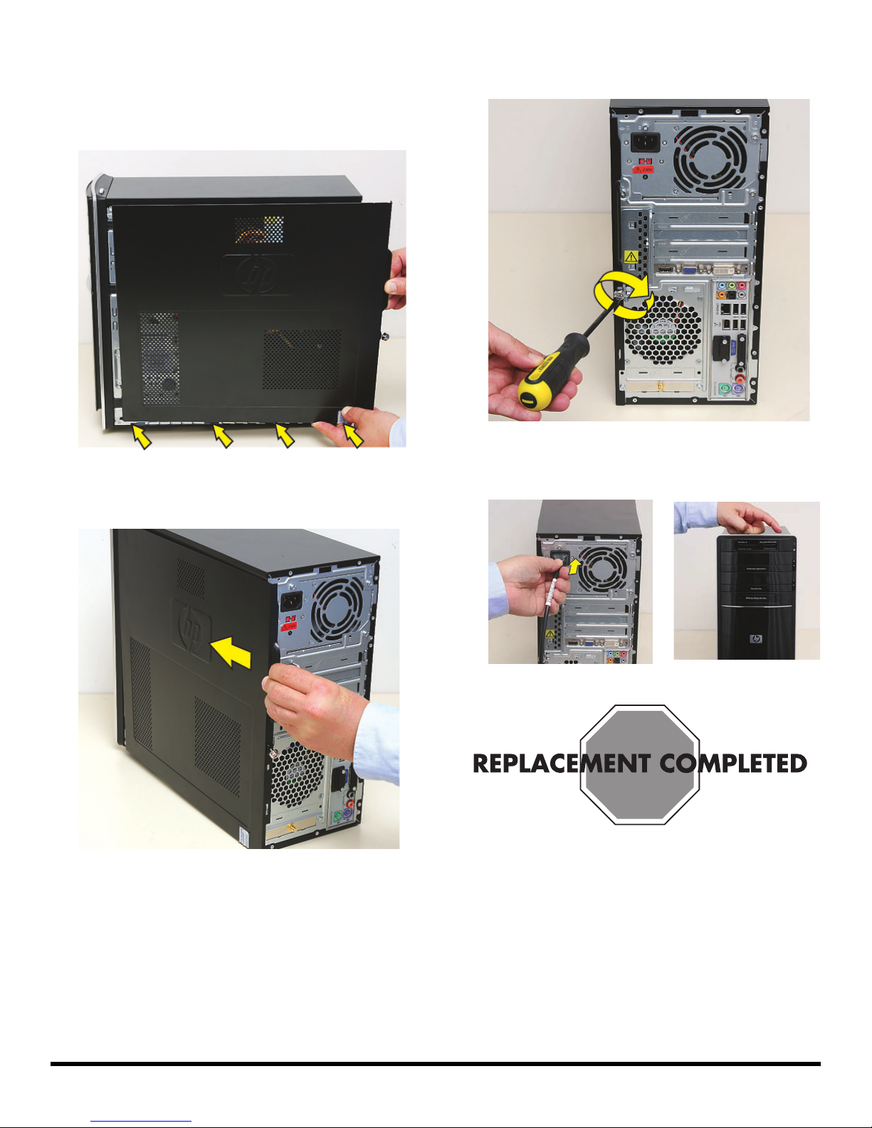
7 Place the bottom of the panel on the computer,
inserting the tabs on the inside of the panel into the
rail slots on the computer. Swing the top of the panel
toward the computer, inserting the top tabs into the
rail slots.
8 Slide the side panel toward the front of the computer
and into place.
9 Tighten the side panel thumbscrew on the back of the
computer.
10 Reconnect all peripherals and cables, and then turn
on the computer.
8 537487-001 — Removing and Replacing an Optical Disc Drive
Page 17
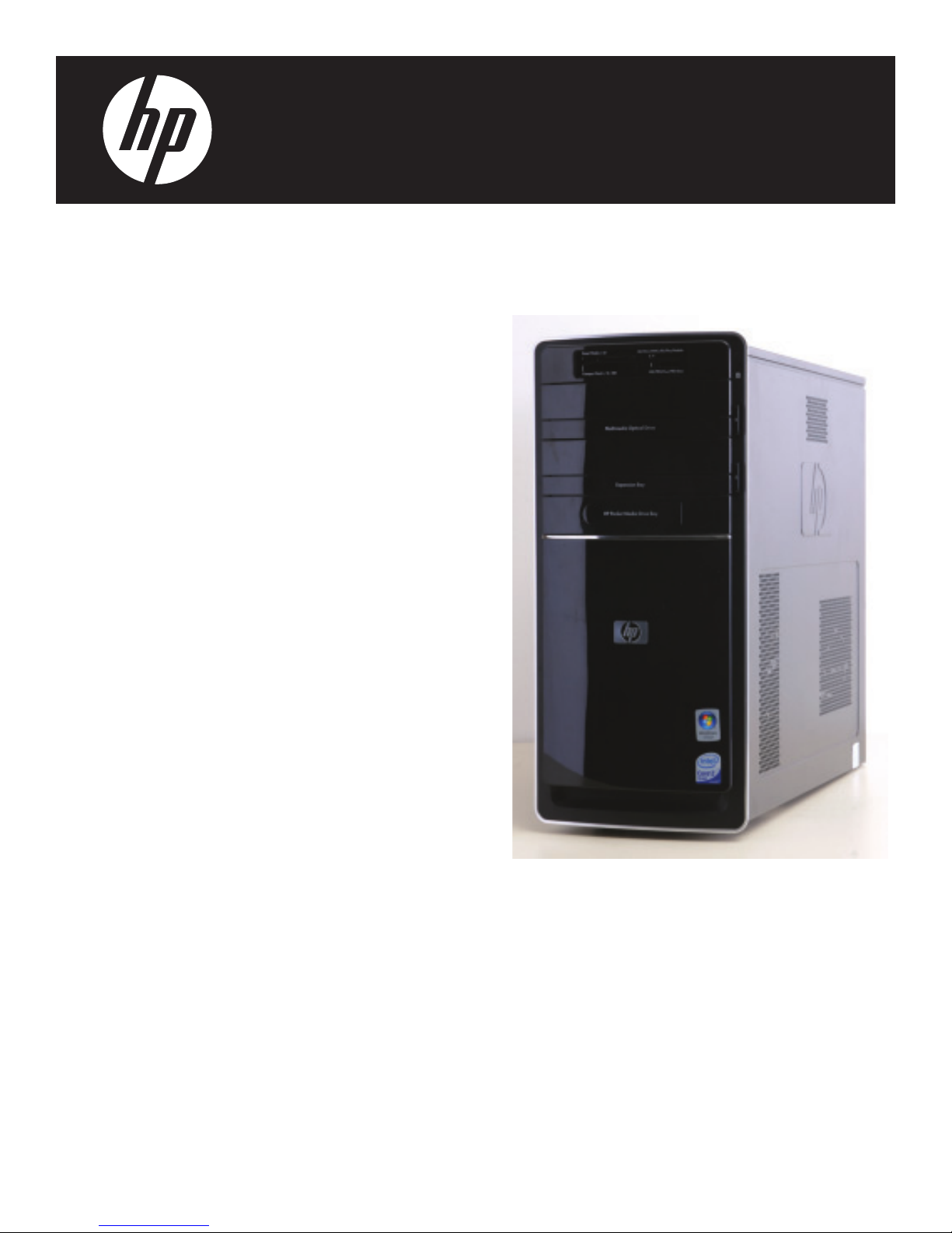
Removing and Replacing a
Hard Disk Drive
Page 18
Removing and Replacing a Hard Disk Drive
25–45 minutes
Before You Begin
Observe the following requirements before removing and
replacing a hard disk drive.
After you replace the operating system hard disk drive,
you may need to perform a system recovery. For detailed
system recovery steps, refer to the documentation that
came with your computer.
IMPORTANT: A hard disk drive is extremely sensitive to
shock impact. Do not bang or drop it. Do not touch the
circuit board. Static electricity can damage the drive.
Tools Needed
Flathead screwdriver
You can use a flathead screwdriver with the
following screw (torque screw).
WARNING:
Never open the cover with the
power cord attached or power
applied. You may damage your
computer or be injured from the
spinning fan blades.
Avoid touching sharp edges
inside the computer.
NOTE: Computer features may vary by model.
Removing a Hard Disk Drive
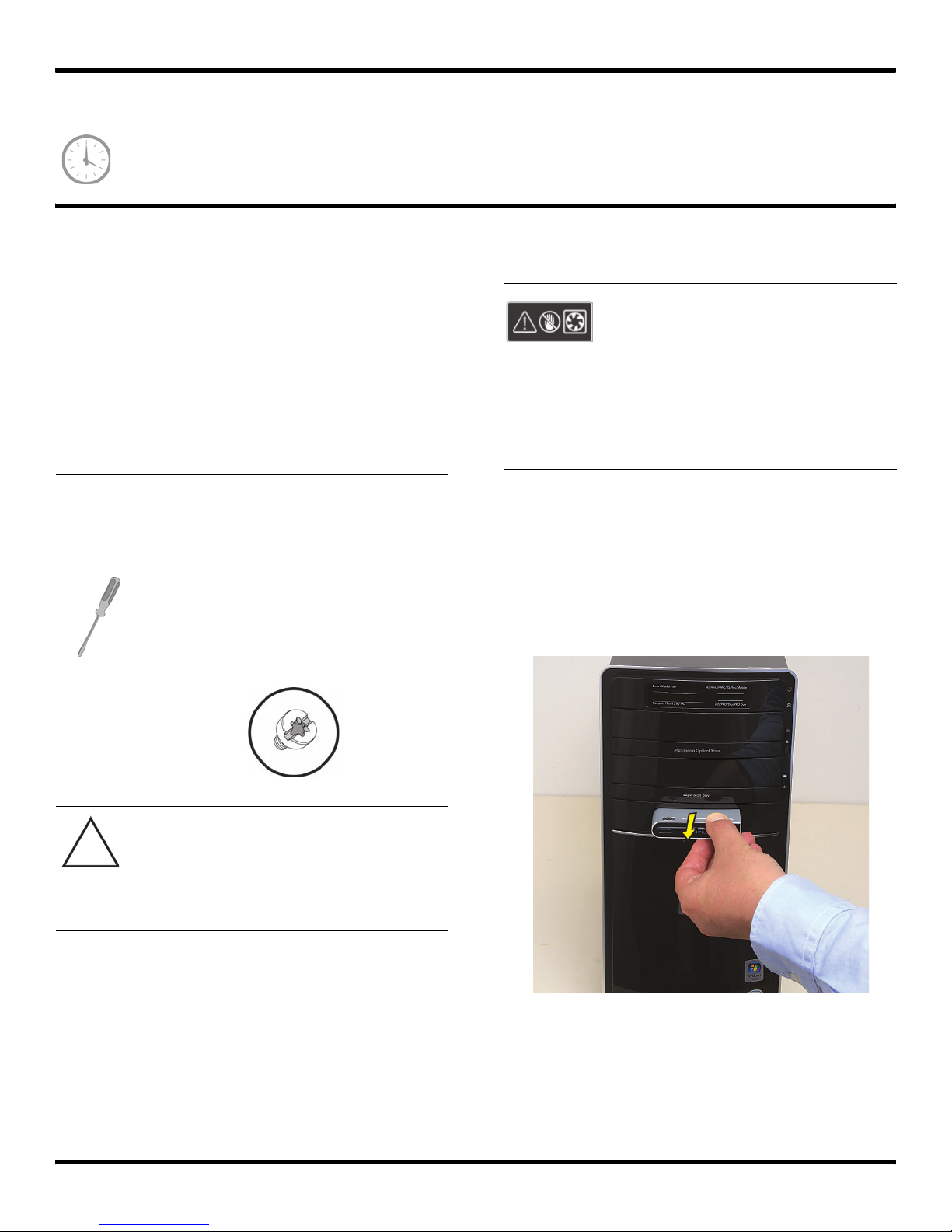
1 Before you begin servicing the computer, remove the
Pocket Media Drive, if it is present.
CAUTION: Static electricity can damage
the electronic components inside the
computer. Discharge static electricity by
touching the metal cage of the computer
before touching any internal parts or
electronic components.
2 537488-001 — Removing and Replacing a Hard Disk Drive
2 Turn off the computer.
Page 19
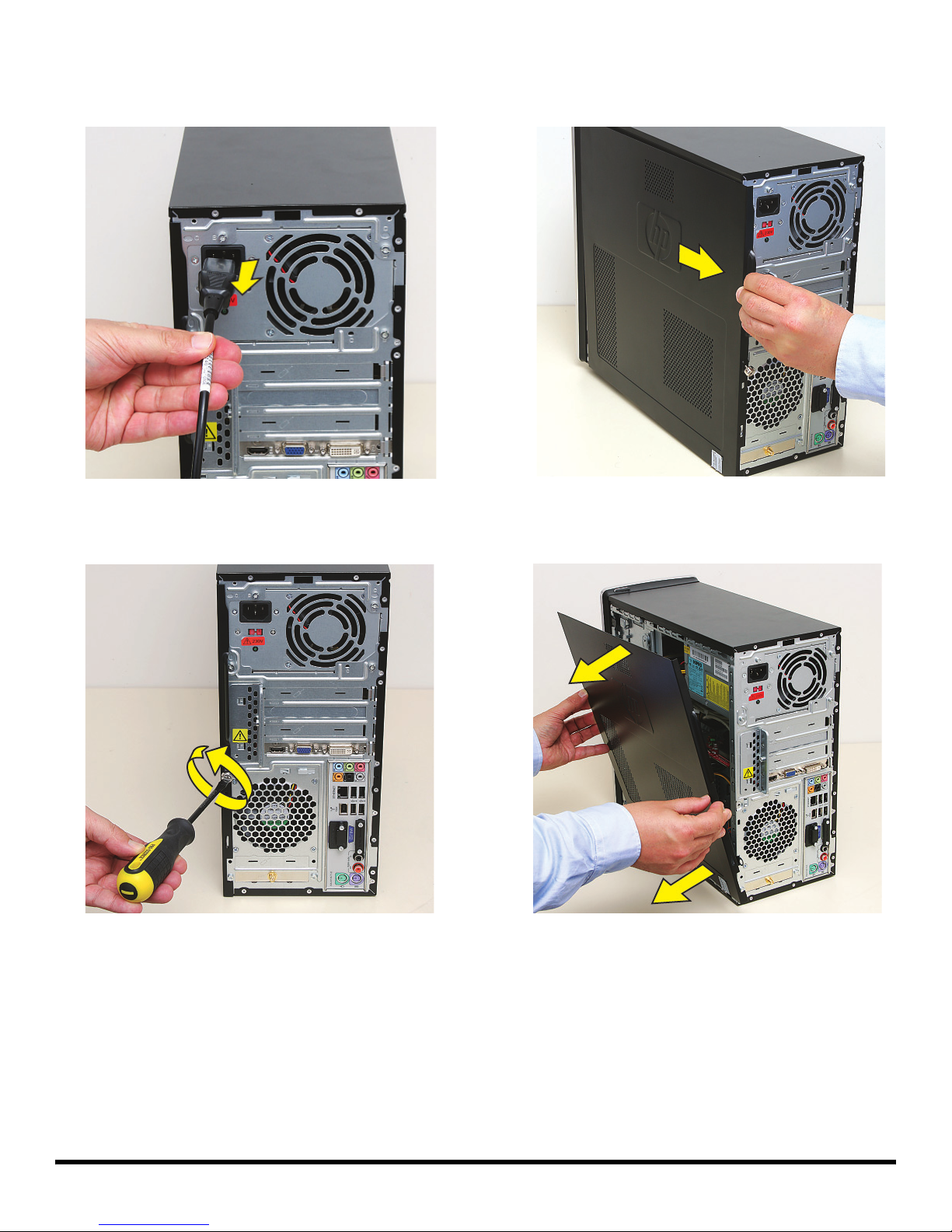
3 Disconnect all peripherals and cables from the front
and the back of the computer. Disconnect the power
cord last.
5 Grasp the handle, and pull the side panel about
2.5 cm (1 inch) toward the back of the computer to
release it.
4 Loosen the side panel thumbscrew on the back of the
computer.
6 Tilt out the top of the side panel, and then lift the panel
from the computer.
--
537488-001 — Removing and Replacing a Hard Disk Drive 3
Page 20
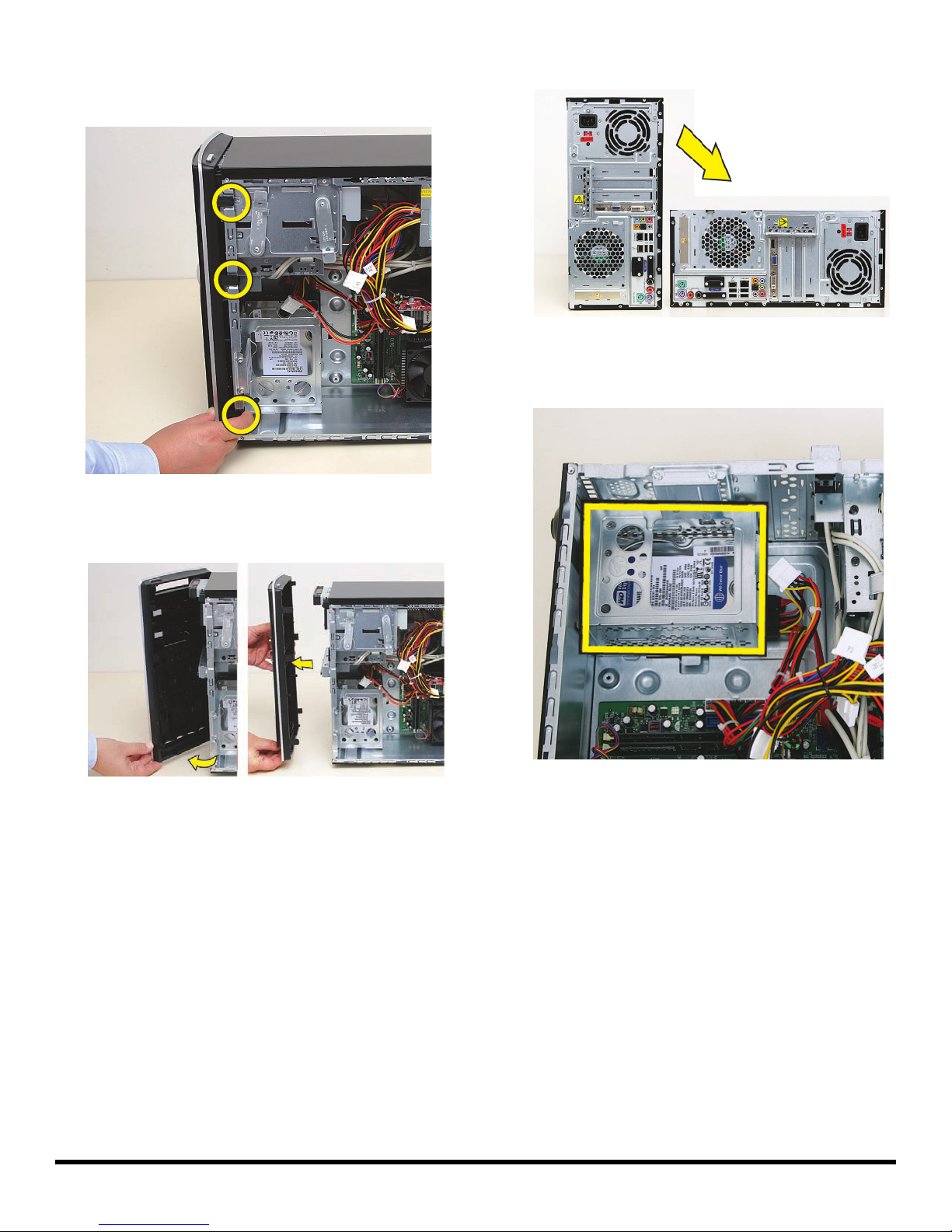
7 Locate the three tabs that secure the front panel to the
computer. Pull each of the tabs out slightly, away from
the computer, to release the panel.
9 Lay the computer on the side.
10 Locate the hard disk drive cage inside the computer.
8 Swing the front panel open toward the left, and then
lift it off the computer.
4 537488-001 — Removing and Replacing a Hard Disk Drive
Page 21
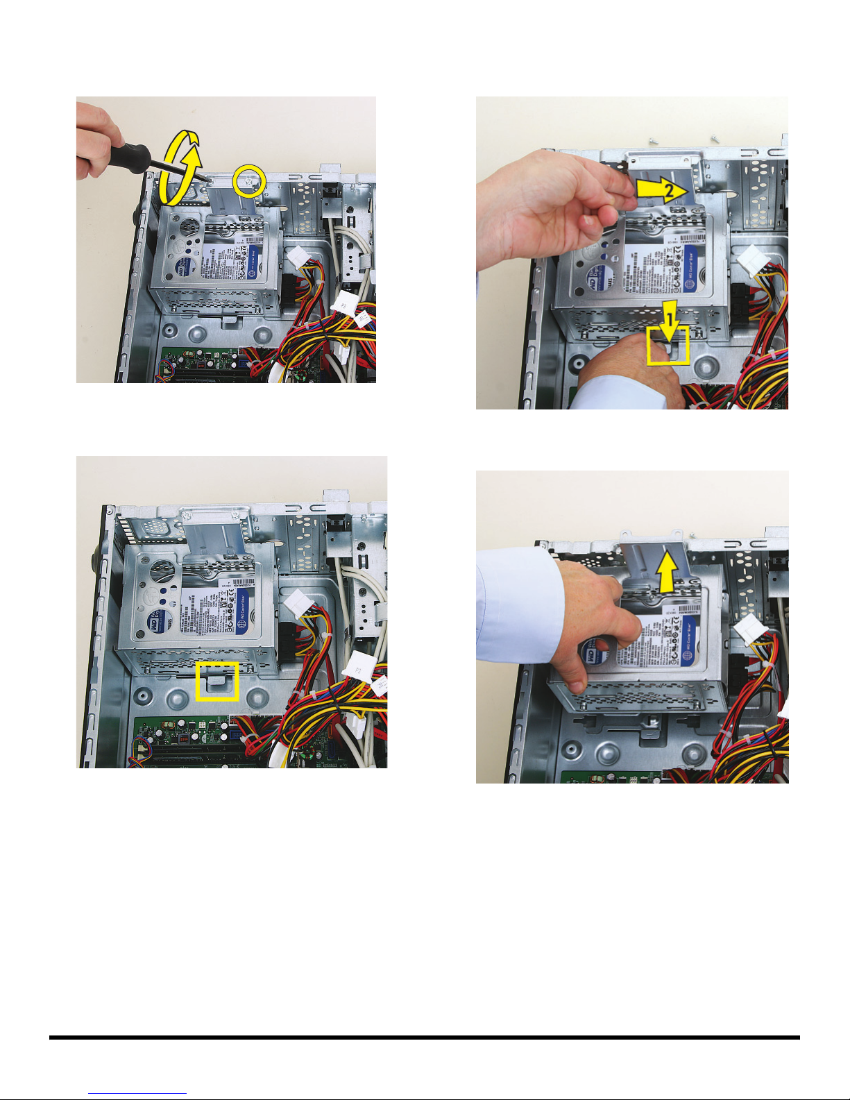
11 Remove the two screws that secure the hard disk drive
cage in the computer.
12 Locate the latch for the hard disk drive cage inside the
computer.
13 Press the cage latch (1), and slide the hard disk drive
cage toward the top of the computer (2) to release it.
14 Lift the cage partway out of the computer.
537488-001 — Removing and Replacing a Hard Disk Drive 5
Page 22
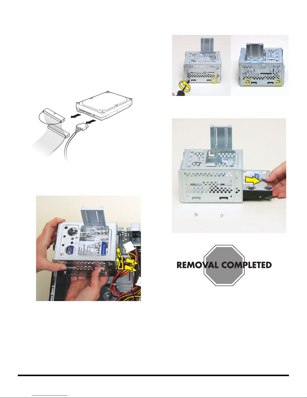
15 Disconnect the cables from the hard disk drive in
the cage:
The plugs on the cables are keyed and can be
inserted only when aligned properly with the
connector on the drive.
In addition, some plugs have a latch that must be
pressed or squeezed to release the plug while pulling
it from the connector.
For plugs without a latch, pull the plug straight out
from the connector.
MASTER
SLAVE
To CPU
16 Remove the four screws (two on each side) that secure
the drive in the cage.
17 Slide the drive out of the cage.
For plugs with a latch, press the latch (1 or 3) in the
center of each plug, and then pull the plug (2 or 4)
from the connector.
6 537488-001 — Removing and Replacing a Hard Disk Drive
Page 23
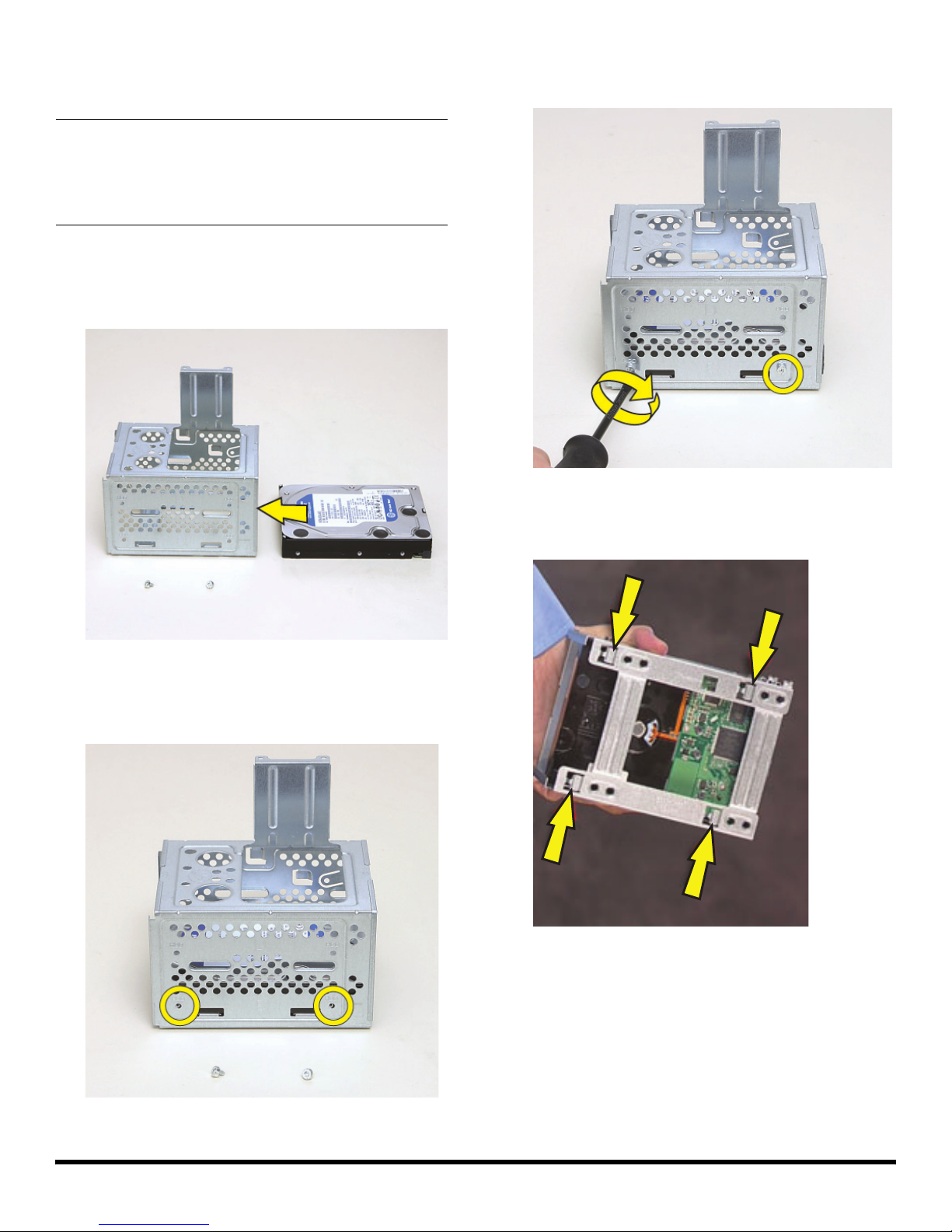
Replacing a Hard Disk Drive
IMPORTANT: The new (replacement) part may not look
the same as the original part, due to different
manufacturers or models. Hewlett-Packard always
provides quality parts that meet or exceed your original
computer specifications.
1 Slide the replacement drive into the hard disk drive
cage, with the label facing up and the connectors
toward the right (the top of the cage).
3 Insert and tighten the four screws that secure the drive
in the cage.
2 Slide the drive into the cage until the four screw holes
in the sides of the drive align with the holes in
the cage.
4 Tip up the hard disk drive cage, and locate the four
tabs on the bottom.
537488-001 — Removing and Replacing a Hard Disk Drive 7
Page 24
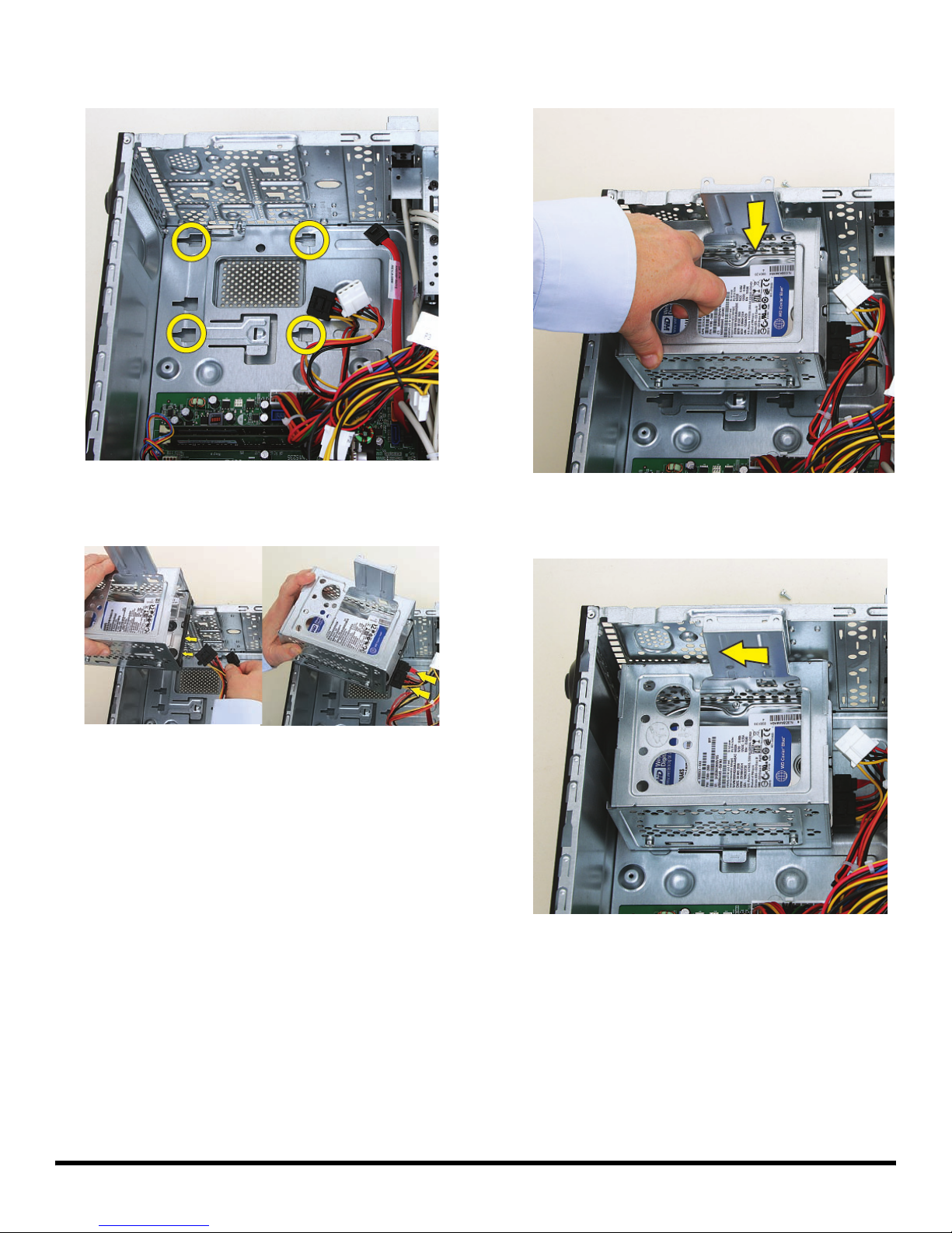
5 Locate the four slots inside the computer that match
the tabs on the bottom of the hard disk drive cage.
7 Lower the cage into the computer, inserting the four
tabs on the bottom of the cage into the computer slots.
6 Hold the cage over the computer, and connect the
hard disk drive power and data cables.
8 Slide the cage toward the bottom of the computer until
it locks into place.
8 537488-001 — Removing and Replacing a Hard Disk Drive
Page 25
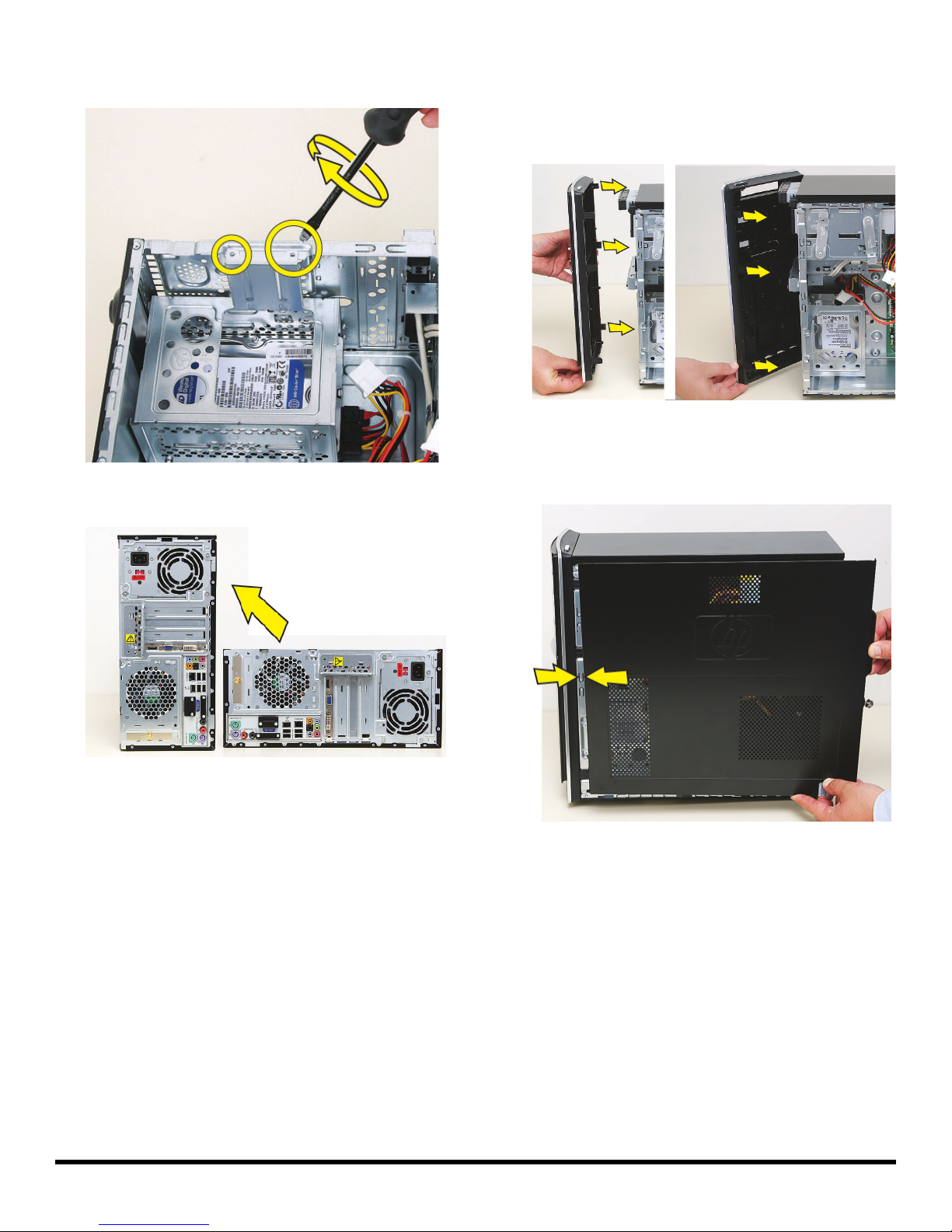
9 Insert and tighten the two screws that secure the cage
in the computer.
10 Set the computer upright.
11 Hold the front panel over the front of the computer,
and then press the left side of the front panel, inserting
the tabs into the computer holes. Swing the right side
of the panel toward the computer, inserting the panel
tabs, and then press it into the computer.
12 Hold the side panel over the side of the computer with
the front edge of the panel about 2.5 cm (1 inch) from
the front of the computer.
537488-001 — Removing and Replacing a Hard Disk Drive 9
Page 26
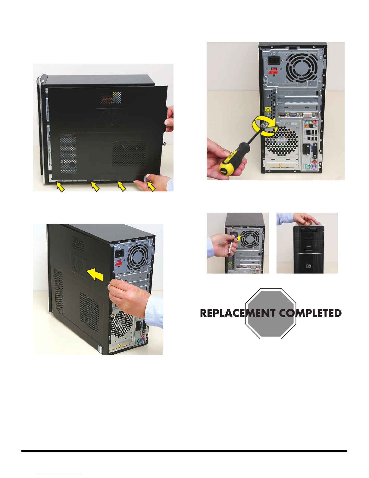
13 Place the bottom of the panel on the computer,
inserting the tabs on the inside of the panel into the
rail slots on the computer. Swing the top of the panel
toward the computer, inserting the top tabs into the
rail slots.
14 Slide the side panel toward the front of the computer
and into place.
15 Tighten the side panel thumbscrew on the back of the
computer.
16 Reconnect all peripherals and cables, and then turn
on the computer.
10 537488-001 — Removing and Replacing a Hard Disk Drive
Page 27
Removing and Replacing an
Add-In Card
Page 28
Removing and Replacing an Add-In Card
15–25 minutes
Before You Begin
Observe the following requirements before removing and
replacing an add-in card.
Tools Needed
Flathead screwdriver
You can use a flathead screwdriver with the
following screw (torque screw).
CAUTION: Static electricity can damage
the electronic components inside the
computer. Discharge static electricity by
touching the metal cage of the computer
before touching any internal parts or
electronic components.
Removing an Add-In Card
1 Before you begin servicing the computer, remove the
Pocket Media Drive, if it is present.
2 Turn off the computer.
WARNING:
Never open the cover with the
power cord attached or power
applied. You may damage your
computer or be injured from the
spinning fan blades.
Avoid touching sharp edges
inside the computer.
NOTE: Computer features may vary by model.
2 537489-001 — Removing and Replacing an Add-In Card
3 Disconnect all peripherals and cables from the front
and the back of the computer. Disconnect the power
cord last.
Page 29
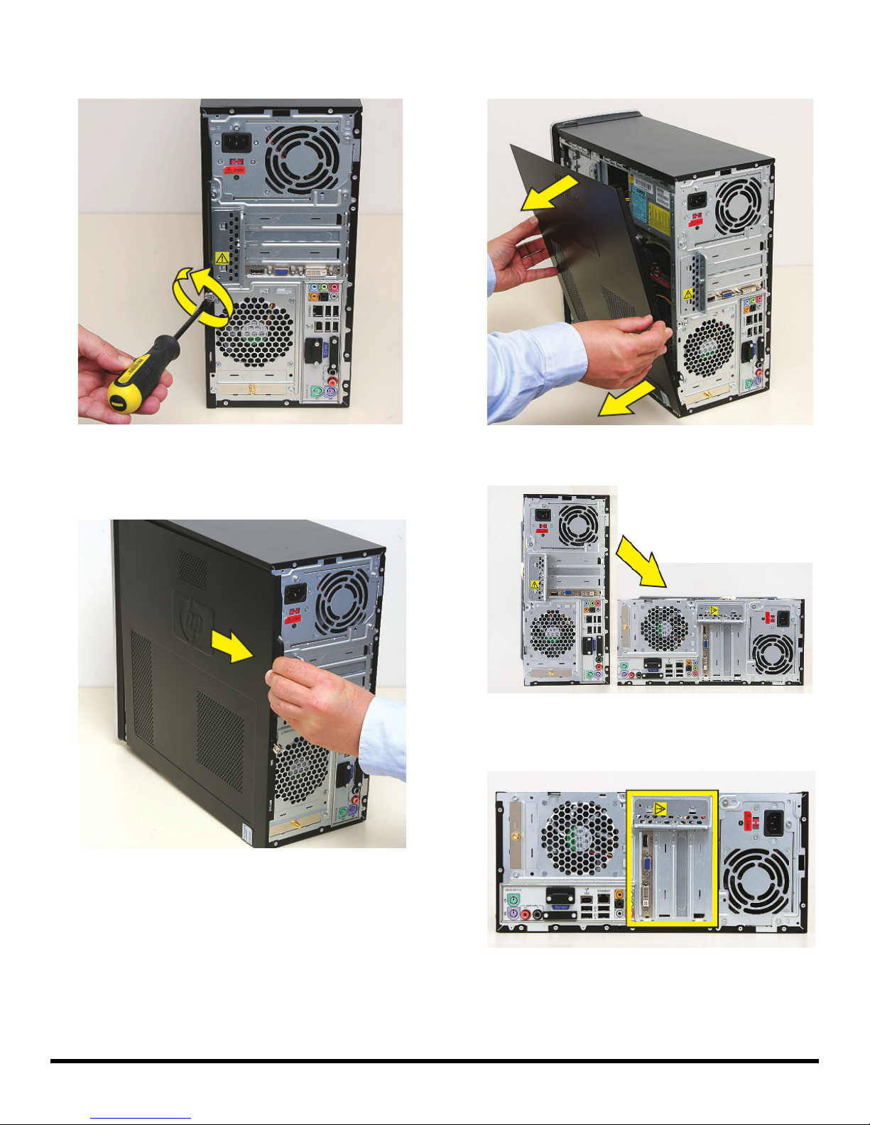
4 Loosen the side panel thumbscrew on the back of the
computer.
6 Tilt out the top of the side panel, and then lift the panel
from the computer.
--
5 Grasp the handle, and pull the side panel about
2.5 cm (1 inch) toward the back of the computer to
release it.
7 Lay the computer on the side.
8 Locate the add-in cards on the back of the computer.
Identify the one you want to replace.
537489-001 — Removing and Replacing an Add-In Card 3
Page 30
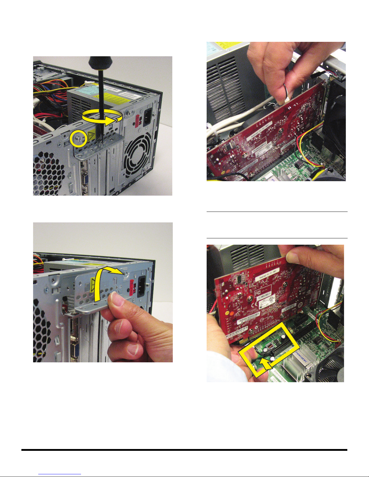
9 On the back of the computer, remove the screw from
the bracket cover for the add-in cards. If it is present,
also remove the additional screw that secures a large
graphics card.
10 Lift off the bracket cover.
11 If present, disconnect any cables connected to
the card.
12 Look at the add-in card socket for a release lever,
which is present on some sockets.
IMPORTANT: Some sockets have a release lever that
must be disengaged to remove the card from the
socket. The release lever style may vary.
4 537489-001 — Removing and Replacing an Add-In Card
Page 31
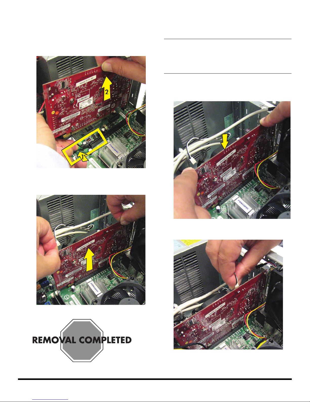
13 Remove the card:
If there is a release lever, place your finger
between the lever and the card, and then push the
lever out (1) as you lift the card (2) from the
socket.
Replacing an Add-In Card
IMPORTANT: The new (replacement) part may not look
the same as the original part, due to different
manufacturers or models. Hewlett-Packard always
provides quality parts that meet or exceed your original
computer specifications.
1 Align the edge of the add-in card with the slot in the
computer, and then press the card straight down until
it is fully seated in the socket.
If there is no release lever, rock the card to free it,
and then lift the card from the socket.
2 Connect any cables to the card.
537489-001 — Removing and Replacing an Add-In Card 5
Page 32
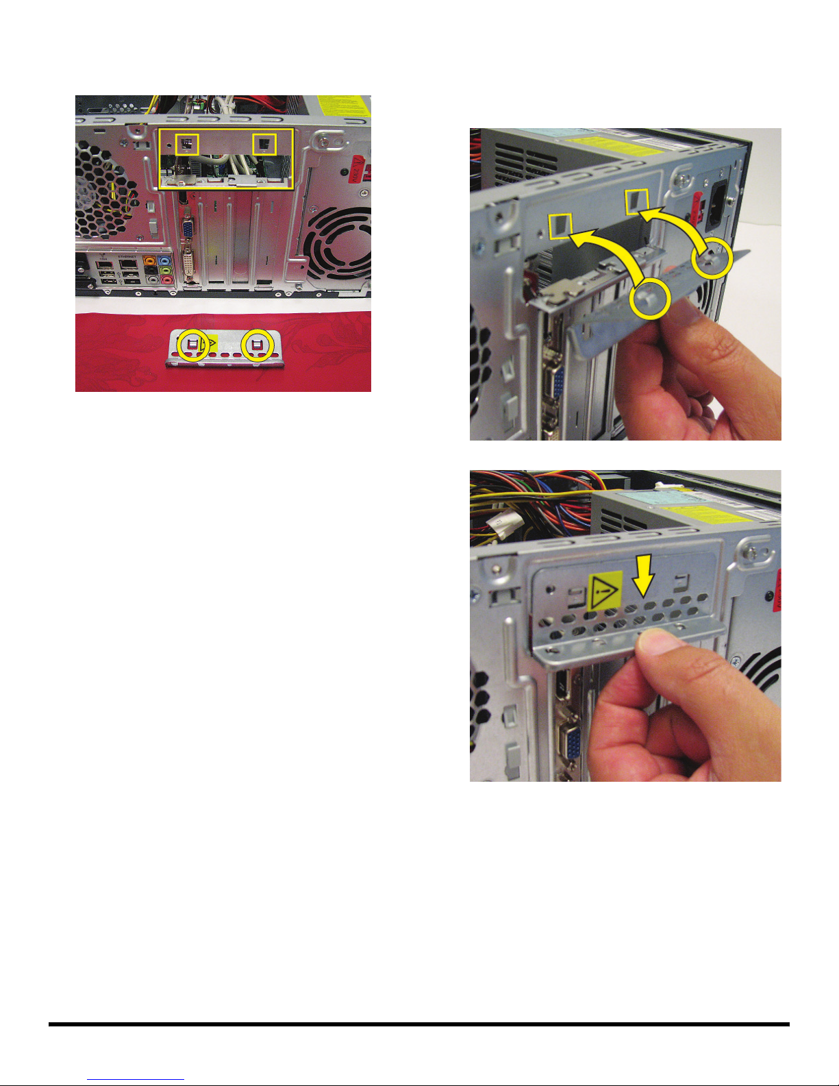
3 Look at the bracket cover for the two hooks that fit
over the two slots on the back of the computer.
4 Replace the bracket cover onto the back of the
computer: Align the bracket cover hooks over the slots
on the computer, and then slide the bracket cover into
place against the add-in cards.
6 537489-001 — Removing and Replacing an Add-In Card
Page 33
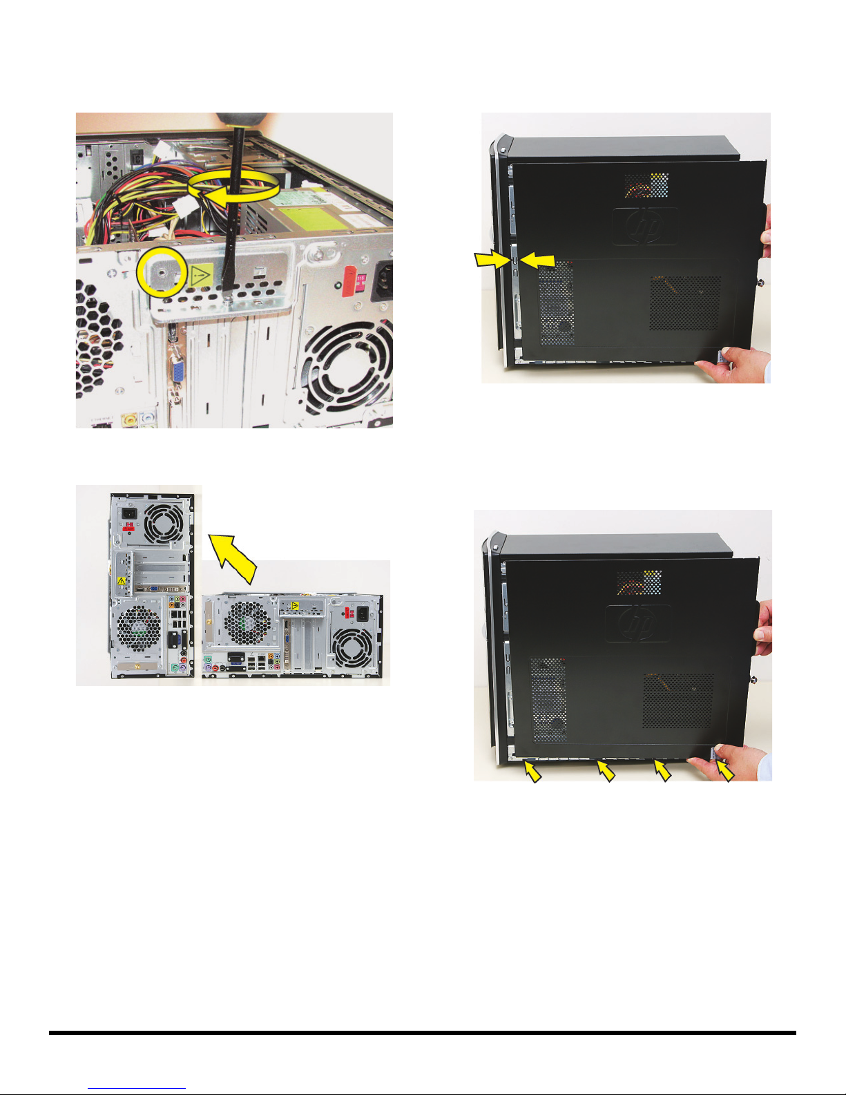
5 Insert and tighten the bracket cover screw. If it is
present, also insert and tighten the additional screw
that secures a large graphics card.
6 Set the computer upright.
7 Hold the side panel over the side of the computer with
the front edge of the panel about 2.5 cm (1 inch) from
the front of the computer.
8 Place the bottom of the panel on the computer,
inserting the tabs on the inside of the panel into the
rail slots on the computer. Swing the top of the panel
toward the computer, inserting the top tabs into the
rail slots.
537489-001 — Removing and Replacing an Add-In Card 7
Page 34
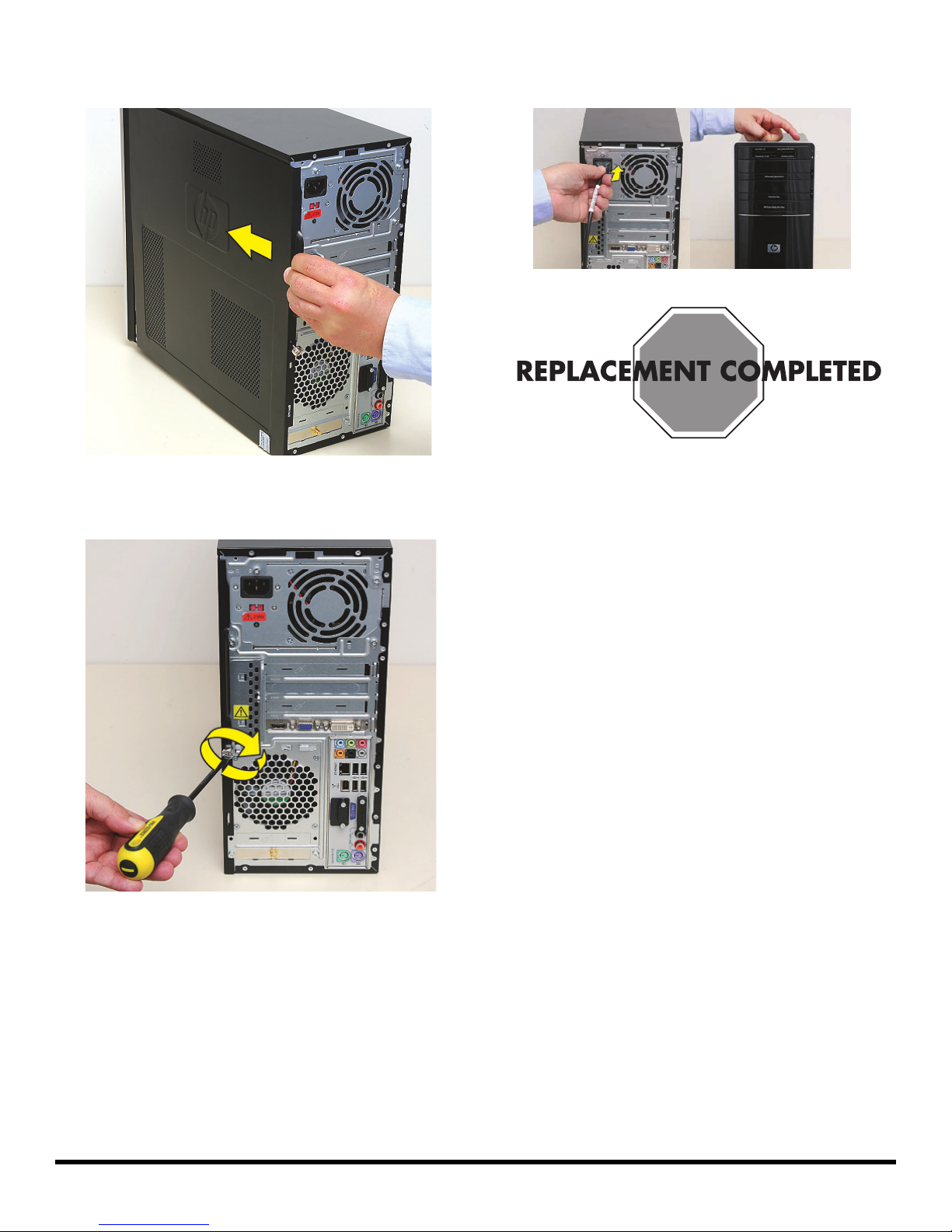
9 Slide the side panel toward the front of the computer
and into place.
10 Tighten the side panel thumbscrew on the back of the
computer.
11 Reconnect all peripherals and cables, and then turn
on the computer.
8 537489-001 — Removing and Replacing an Add-In Card
Page 35
Removing and Replacing the
Memory Card Reader
Page 36
Removing and Replacing the Memory Card Reader
15–25 minutes
Before You Begin
Observe the following requirements before removing and
replacing the memory card reader.
Tools Needed
Flathead screwdriver
You can use a flathead screwdriver with the
following screw (torque screw).
CAUTION: Static electricity can damage
the electronic components inside the
computer. Discharge static electricity by
touching the metal cage of the computer
before touching any internal parts or
electronic components.
Removing the Memory Card
Reader
1 Before you begin servicing the computer, remove the
Pocket Media Drive, if it is present.
2 Turn off the computer.
WARNING:
Never open the cover with the
power cord attached or power
applied. You may damage your
computer or be injured from the
spinning fan blades.
Avoid touching sharp edges
inside the computer.
NOTE: Computer features may vary by model.
2 571044-001 — Removing and Replacing the Memory Card Reader
3 Disconnect all peripherals and cables from the front
and the back of the computer. Disconnect the power
cord last.
Page 37
4 Loosen the side panel thumbscrew on the back of the
computer.
6 Tilt out the top of the side panel, and then lift the panel
from the computer.
--
5 Grasp the handle, and pull the side panel about
2.5 cm (1 inch) toward the back of the computer to
release it.
7 Locate the three tabs that secure the front panel to the
computer. Pull each of the tabs out slightly, away from
the computer, to release the panel.
571044-001 — Removing and Replacing the Memory Card Reader 3
Page 38
8 Swing the front panel open toward the left, and then
lift it off the computer.
9 Locate the memory card reader at the top of the front
of the computer.
10 Remove the screw that secures the reader in the
computer.
11 Push the reader slightly to the left to release it.
4 571044-001 — Removing and Replacing the Memory Card Reader
Page 39
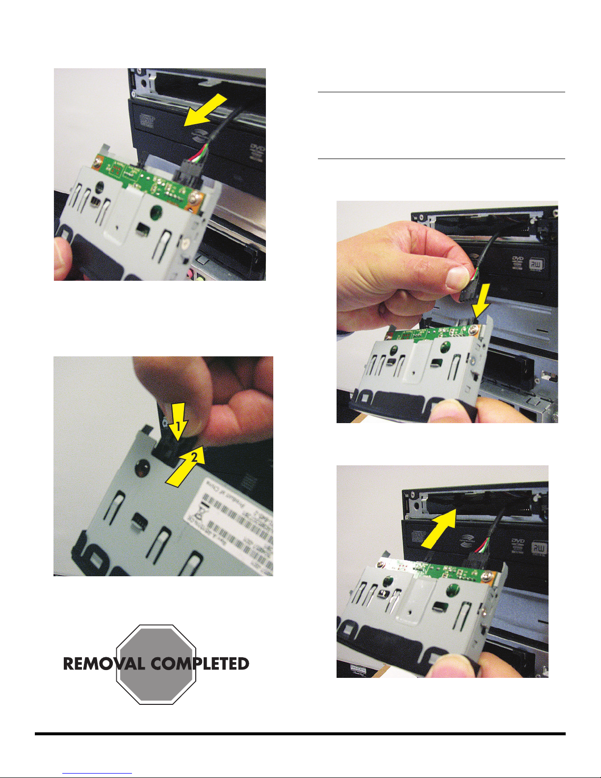
12 Pull the reader partway out through the front of the
computer.
13 Turn over the reader, press the latch in the center of
the plug (1), and then pull the plug (2) from the
connector.
Replacing the Memory Card
Reader
IMPORTANT: The new (replacement) part may not look
the same as the original part, due to different
manufacturers or models. Hewlett-Packard always
provides quality parts that meet or exceed your original
computer specifications.
1 Connect the cable to the back of the reader.
2 Insert the reader into the computer.
571044-001 — Removing and Replacing the Memory Card Reader 5
Page 40
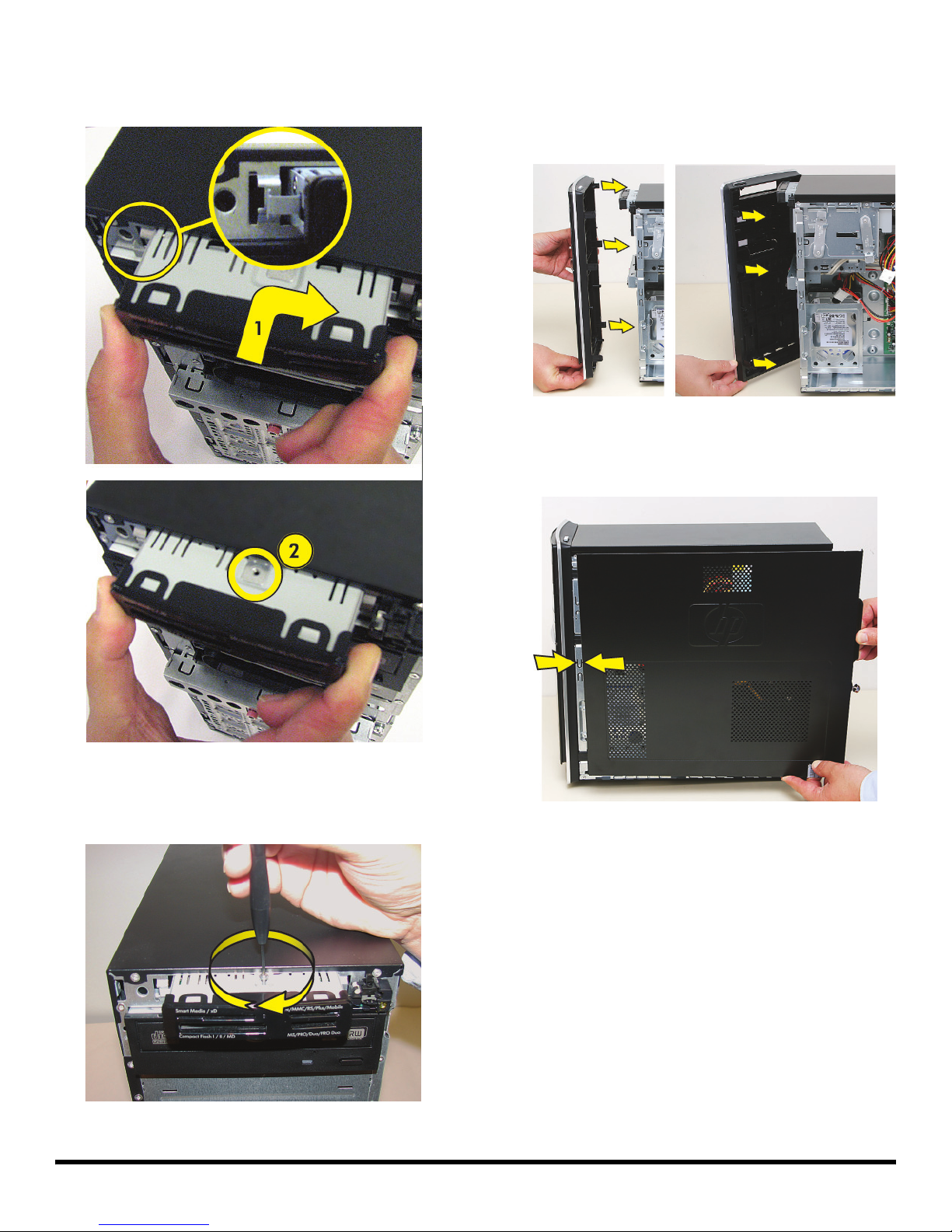
3 Slide the reader in and slightly to the right to lock the
tab into the slot (1) and to align the screw hole on the
top of the reader with the computer screw hole (2).
5 Hold the front panel over the front of the computer,
and then press the left side of the front panel, inserting
the tabs into the computer holes. Swing the right side
of the panel toward the computer, inserting the panel
tabs, and then press it into the computer.
6 Hold the side panel over the side of the computer with
the front edge of the panel about 2.5 cm (1 inch) from
the front of the computer.
4 Insert and tighten the screw that secures the reader in
the computer.
6 571044-001 — Removing and Replacing the Memory Card Reader
Page 41
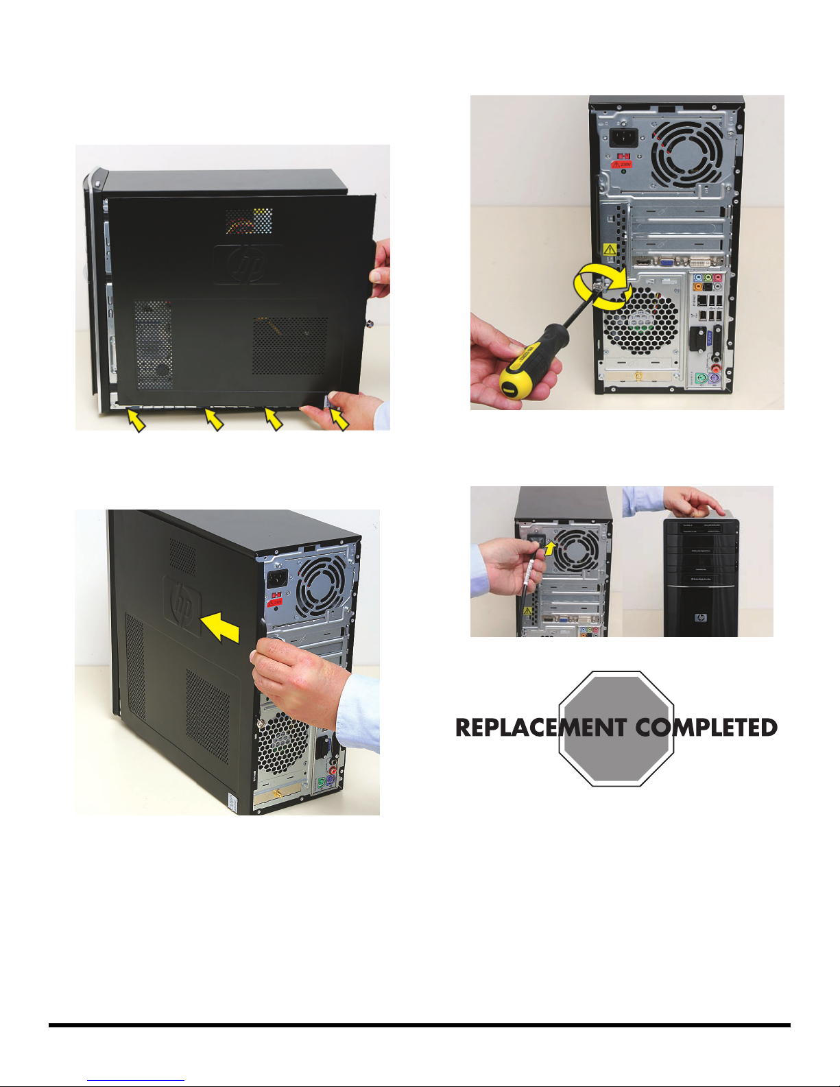
7 Place the bottom of the panel on the computer,
inserting the tabs on the inside of the panel into the
rail slots on the computer. Swing the top of the panel
toward the computer, inserting the top tabs into the
rail slots.
8 Slide the side panel toward the front of the computer
and into place.
9 Tighten the side panel thumbscrew on the back of the
computer.
10 Reconnect all peripherals and cables, and then turn
on the computer.
571044-001 — Removing and Replacing the Memory Card Reader 7
Page 42

8 571044-001 — Removing and Replacing the Memory Card Reader
Page 43
Removing and Replacing Memory
Page 44
Removing and Replacing Memory
15–25 minutes
Before You Begin
Use the product specification for your model to find the
correct type of DIMM (dual in-line memory module) for
your computer and the maximum memory amount.
Memory upgrades may not be needed. Many computers
already have the maximum amount of memory installed.
Observe the following requirements before removing and
replacing memory.
Tools Needed
Flathead screwdriver
You can use a flathead screwdriver with the
following screw (torque screw).
WARNING:
Never open the cover with the
power cord attached or power
applied. You may damage your
computer or be injured from the
spinning fan blades.
Avoid touching sharp edges
inside the computer.
NOTE: Computer features may vary by model.
Removing Memory
1 Before you begin servicing the computer, remove the
Pocket Media Drive, if it is present.
CAUTION: Static electricity can damage
the electronic components inside the
computer. Discharge static electricity by
touching the metal cage of the computer
before touching any internal parts or
electronic components.
2 Turn off the computer.
2 537486-001 — Removing and Replacing Memory
Page 45
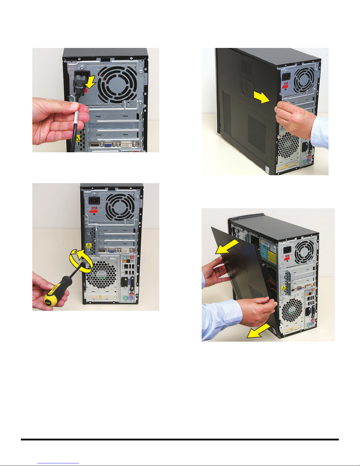
3 Disconnect all peripherals and cables from the front
and the back of the computer. Disconnect the power
cord last.
4 Loosen the side panel thumbscrew on the back of the
computer.
5 Grasp the handle, and pull the side panel about
2.5 cm (1 inch) toward the back of the computer to
release it.
6 Tilt out the top of the side panel, and then lift the panel
from the computer.
--
537486-001 — Removing and Replacing Memory 3
Page 46
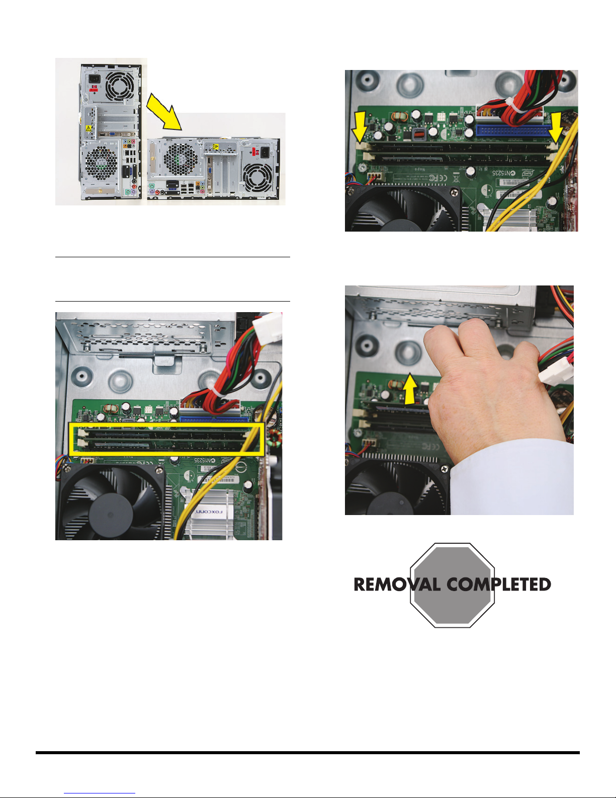
7 Lay the computer on the side.
8 Locate the memory sockets on your computer
motherboard.
NOTE: The location and number of memory sockets
may vary with the motherboard model in your
computer.
9 Push down the retaining clip on each end of the
memory socket to release the memory module.
10 Touching only the top edge of the memory module, lift
it out of the socket.
4 537486-001 — Removing and Replacing Memory
Page 47
Replacing Memory
IMPORTANT: The new (replacement) part may not look
the same as the original part, due to different
manufacturers or models. Hewlett-Packard always
provides quality parts that meet or exceed your original
computer specifications.
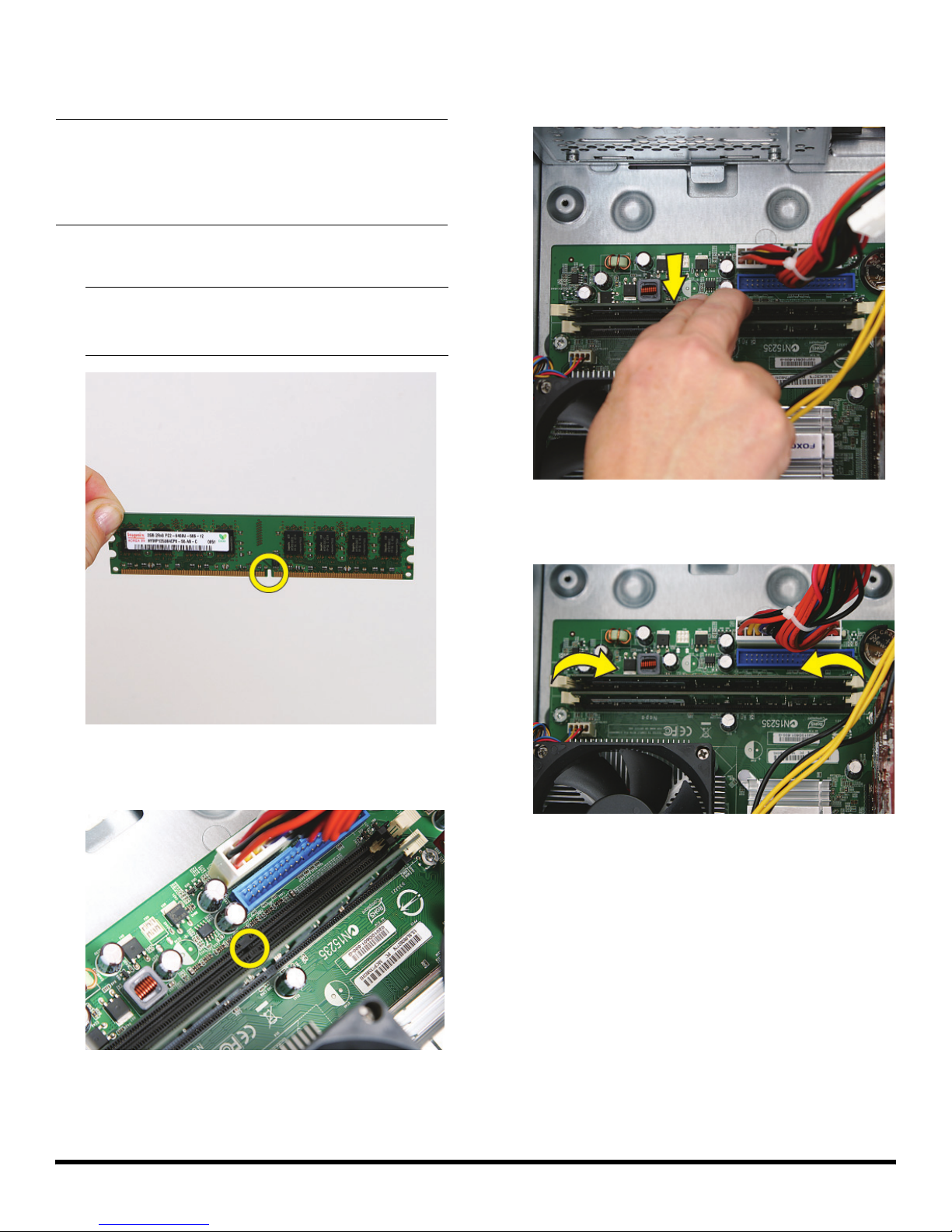
1 Touching only the top edge of the memory module,
locate the notch on the bottom edge.
NOTE: Each type of memory has a different notch
position. Incompatible memory modules cannot be
installed in the memory socket.
3 Position the memory module over the socket, aligning
the notch with the tab in the socket, and then firmly
press the module down into the socket...
2 Look at the memory module socket for the tab that
matches the notch on the memory module.
...until the retaining clips at the ends of the socket lock
the module into place.
537486-001 — Removing and Replacing Memory 5
Page 48
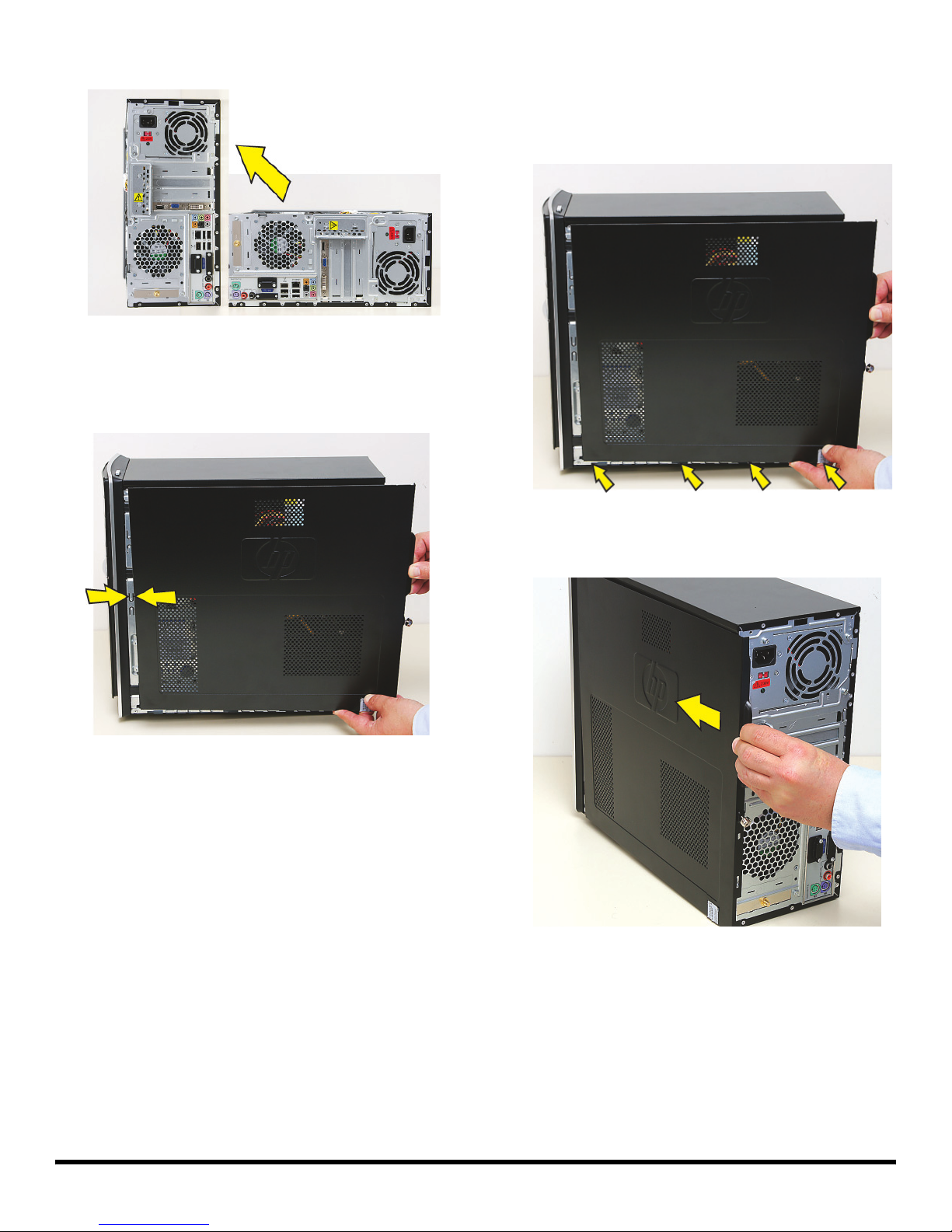
4 Set the computer upright.
5 Hold the side panel over the side of the computer with
the front edge of the panel about 2.5 cm (1 inch) from
the front of the computer.
6 Place the bottom of the panel on the computer,
inserting the tabs on the inside of the panel into the
rail slots on the computer. Swing the top of the panel
toward the computer, inserting the top tabs into the
rail slots.
7 Slide the side panel toward the front of the computer
and into place.
6 537486-001 — Removing and Replacing Memory
Page 49
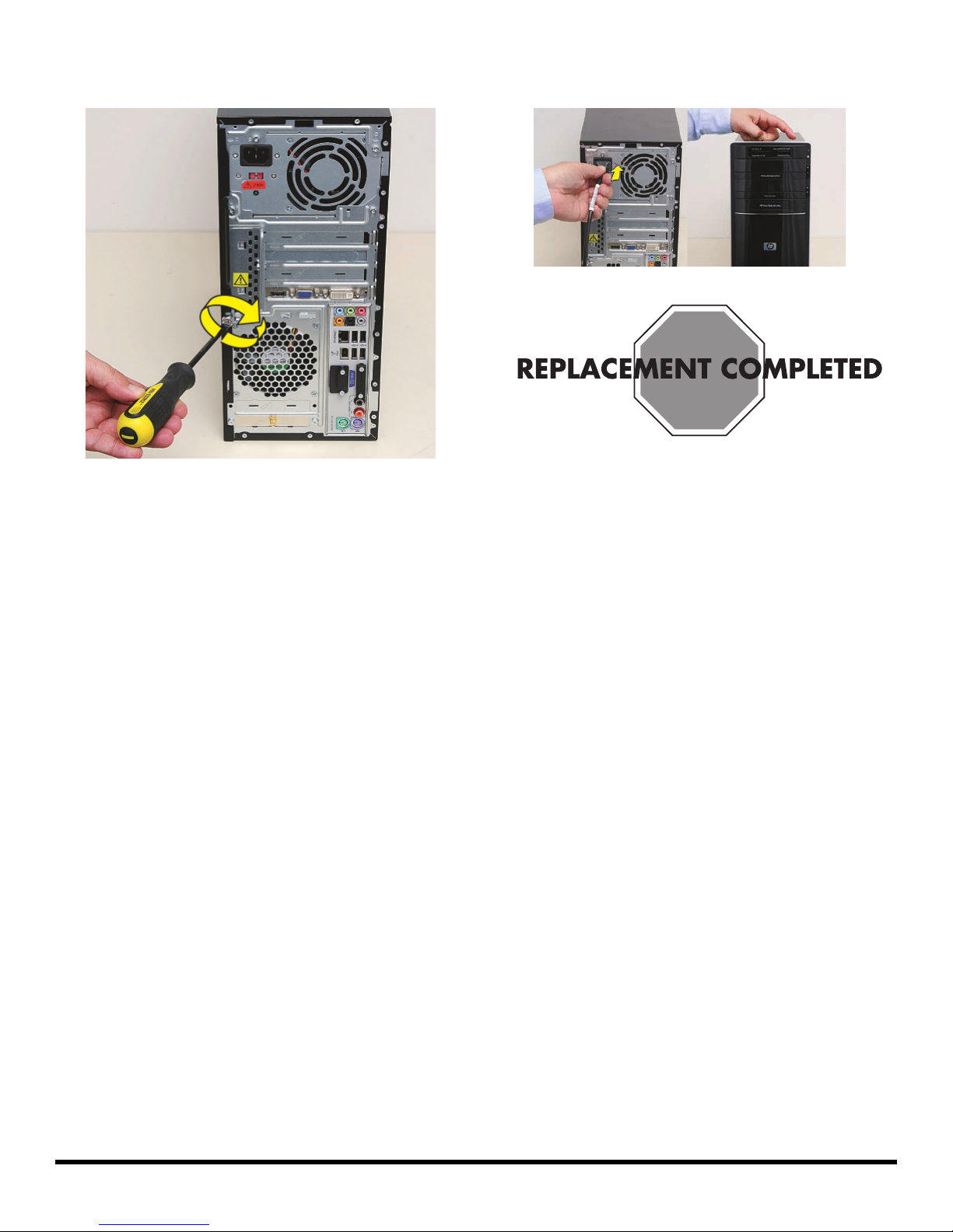
8 Tighten the side panel thumbscrew on the back of the
computer.
9 Reconnect all peripherals and cables, and then turn
on the computer.
537486-001 — Removing and Replacing Memory 7
Page 50

© Copyright 2009 Hewlett-Packard Development Company, L.P.
The information contained herein is subject to change without notice.
Vers ion: 1 . 0
 Loading...