

Page 1
Page 2

Please check out our eBay auctions for more great
deals on Factory Service Manuals:
Page 3

Notice
In a continuing effort to improve the quality of our products, technical and environmental information
in this document is subject to change without notice.
This manual and any examples contained herein are provided “as is” and are subject to change
without notice. Hewlett-Packard Company makes no warranty of any kind with regard to this manual,
including, but not limited to, the implied warranties of merchantability and fitness for a particular
purpose. Hewlett-Packard Co. shall not be liable for any errors or for incidental or consequential
damages in connection with the furnishing, performance, or use of this manual or the examples herein.
Consumer transactions in Australia and the United Kingdom: The above disclaimers and limitations
shall not apply to Consumer transactions in Australia and the United Kingdom and shall not affect the
statutory rights of Consumers.
© Copyright Hewlett-Packard Company 2000. All rights reserved. Reproduction, adaptation, or
translation of this manual is prohibited without prior written permission of Hewlett-Packard
Company, except as allowed under the copyright laws.
The programs that control this product are copyrighted and all rights are reserved. Reproduction,
adaptation, or translation of those programs without prior written permission of Hewlett-Packard Co.
is also prohibited.
Portions of the programs that control this product may also be copyrighted by Microsoft Corporation,
SystemSoft Corporation, Crystal Semiconductor Corporation, Phoenix Technologies, Ltd., Silicon
Motion Corporation, ESS, and Adobe Systems Incorporated. See the individual programs for
additional copyright notices.
Microsoft®, MS-DOS®, and Windows® are U.S. registered trademarks of Microsoft Corporation.
Pentium® and the Intel Inside logo are U.S. registered trademarks of Intel Corporation. Adobe® and
Acrobat® are trademarks of Adobe Systems Incorporated.
All certifications may not be completed at product introduction. Check with your HP reseller for
certification status.
This equipment is subject to FCC rules. It will comply with the appropriate FCC rules before final
delivery to the buyer.
Hewlett-Packard Company
Mobile Computing Division
19310 Pruneridge Ave.
Cupertino, CA 95014, U.S.A.
Edition History
Edition 1......................... August 2000
ii HP OmniBook XE3
Page 4

Contents
1. Product Information ................................................................................................. 1-1
Technology Codes.........................................................................................................................1-2
Features .........................................................................................................................................1-3
Operation....................................................................................................................................... 1-6
Turning the Notebook On and Off ......................................................................................... 1-6
Checking the Notebook’s Status ............................................................................................ 1-7
Using Fn Hot Keys................................................................................................................. 1-9
Resetting the Notebook ........................................................................................................ 1-10
Using the CD-ROM or DVD Player .................................................................................... 1-11
Specifications .............................................................................................................................. 1-12
Hardware Specifications....................................................................................................... 1-12
Software Specifications........................................................................................................ 1-14
System Resources................................................................................................................. 1-15
Internal Design............................................................................................................................1-18
2. Removal and Replacement .......................................................................................2-1
Disassembly Flowchart ................................................................................................................. 2-2
Removing the Battery (User-Replaceable) ................................................................................... 2-4
Removing an SDRAM Module (User-Replaceable)..................................................................... 2-5
Removing the Mini-PCI PCA (User-Replaceable).......................................................................2-7
Removing the Keyboard Cover (with Hinge Covers) (User-Replaceable)...................................2-9
Removing the Keyboard (User-Replaceable) ............................................................................. 2-11
Removing the Hard Disk Drive Assembly (User-Replaceable).................................................. 2-13
Replacing Small Parts (User-Replaceable) ................................................................................. 2-16
Removing the Display Assembly (HP Authorized Service Providers Only)..............................2-17
Removing the Top Case (HP Authorized Service Providers Only)............................................ 2-20
Removing the CD Player PCA (HP Authorized Service Providers Only).................................. 2-22
Removing the Hinge Saddle Set (HP Authorized Service Providers Only) ............................... 2-23
Removing the Video PCA (HP Authorized Service Providers Only)......................................... 2-25
Removing the Heatsink Assembly (with Fan) (HP Authorized Service Providers Only).......... 2-27
Removing the CPU Module (HP Authorized Service Providers Only)...................................... 2-29
Removing the Floppy Disk Drive (HP Authorized Service Providers Only) ............................. 2-31
Removing the CD-ROM/DVD Drive (HP Authorized Service Providers Only) ....................... 2-33
Removing the Motherboard or Bottom Case (HP Authorized Service Providers Only) ............ 2-34
Reinstalling the Motherboard............................................................................................... 2-37
Replacing the Bottom Case.................................................................................................. 2-38
Removing Notebook Components (HP Authorized Service Providers Only)............................2-40
HP OmniBook XE3 iii
Page 5

3. Troubleshooting and Diagnostics............................................................................. 3-1
Troubleshooting ............................................................................................................................ 3-2
Troubleshooting the Problem................................................................................................. 3-3
Verifying the Repair............................................................................................................... 3-3
Suggestions for Troubleshooting ........................................................................................... 3-4
Diagnostic Tools ......................................................................................................................... 3-17
DiagTools............................................................................................................................. 3-17
Power-On Self-Test..............................................................................................................3-24
Sycard PCCtest 450 CardBus Card (Optional) .................................................................... 3-27
Desktop Management Interface (DMI)................................................................................ 3-28
BIOS Setup Utility ............................................................................................................... 3-30
4. Replaceable Parts ......................................................................................................4-1
5. Reference Information..............................................................................................5-1
Password Removal Policy............................................................................................................. 5-1
Hewlett-Packard Display Quality Statement ................................................................................ 5-2
Service Notes ................................................................................................................................ 5-4
iv HP OmniBook XE3
Page 6

Figures
Figure 1-1. Top/Right View................................................................................................................. 1-3
Figure 1-2. Front View......................................................................................................................... 1-4
Figure 1-3. Rear/Left View.................................................................................................................. 1-4
Figure 1-4. Bottom View ..................................................................................................................... 1-5
Figure 1-5. Status Lights...................................................................................................................... 1-7
Figure 1-6. Resetting the Notebook................................................................................................... 1-10
Figure 1-7. Multimedia Buttons......................................................................................................... 1-11
Figure 1-8. Replaceable Module Diagram......................................................................................... 1-18
Figure 2-1. Disassembly Flow ............................................................................................................. 2-2
Figure 2-2. Removing the Battery........................................................................................................ 2-4
Figure 2-3. Removing the SDRAM Cover .......................................................................................... 2-5
Figure 2-4. Removing an SDRAM Module......................................................................................... 2-6
Figure 2-5. Removing the Mini-PCI Card ........................................................................................... 2-8
Figure 2-6. Removing the Keyboard Cover Retaining Screws............................................................2-9
Figure 2-7. Removing the Keyboard Cover....................................................................................... 2-10
Figure 2-8. Loosening the Keyboard Retaining Screws .................................................................... 2-11
Figure 2-9. Disconnecting the Keyboard Cable................................................................................. 2-12
Figure 2-10. Removing the Hard Disk Drive.....................................................................................2-13
Figure 2-11. Removing the Hard Disk Carrier................................................................................... 2-14
Figure 2-12. Removing the Display................................................................................................... 2-18
Figure 2-13. Video PCA DIP Switches.............................................................................................. 2-19
Figure 2-14. Removing the Top Case Retaining Screws...................................................................2-20
Figure 2-15. Removing the Top Case................................................................................................ 2-21
Figure 2-16. Removing the CD Player PCA...................................................................................... 2-22
Figure 2-17. Removing the Hinge Saddle Retaining Screws............................................................. 2-23
Figure 2-18. Removing the Hinge Saddle..........................................................................................2-24
Figure 2-19. Removing the Video PCA.............................................................................................2-26
Figure 2-20. Removing the Heatsink Assembly................................................................................ 2-28
Figure 2-21. Removing the CPU Module.......................................................................................... 2-30
Figure 2-22. Removing the Floppy Disk Drive ................................................................................. 2-32
Figure 2-23. Removing the CD-ROM/DVD Drive............................................................................ 2-33
Figure 2-24. Removing the Motherboard...........................................................................................2-36
Figure 2-25. Installing Docking Doors .............................................................................................. 2-38
Figure 2-26. Installing the PCMCIA Doors....................................................................................... 2-39
Figure 2-27. Example of Serial Number Label.................................................................................. 2-39
Figure 3-1. Basic Troubleshooting Steps............................................................................................. 3-2
Figure 3-2. DiagTools Screens — Basic and Advanced....................................................................3-17
Figure 3-3. Serial and Parallel Loopback Connectors ....................................................................... 3-19
Figure 4-1. Exploded View.................................................................................................................. 4-2
HP OmniBook XE3 v
Page 7

Tables
Table 1-1. OmniBook XE3 Series Models .......................................................................................... 1-1
Table 1-2. Activating Power Modes.................................................................................................... 1-6
Table 1-3. Status Lights....................................................................................................................... 1-8
Table 1-4. Fn Hot Keys........................................................................................................................ 1-9
Table 1-5. XE3 Series Hardware Specifications................................................................................ 1-12
Table 1-6. XE3 Series Software Specifications................................................................................. 1-14
Table 1-7. System Interrupts.............................................................................................................. 1-15
Table 1-8. System Memory................................................................................................................ 1-15
Table 1-9. System Input/Output Addresses (100-3FF)...................................................................... 1-16
Table 1-10. DMA Channels............................................................................................................... 1-16
Table 1-11. XE3 Series Accessories.................................................................................................. 1-17
Table 1-12. Functional Structure ....................................................................................................... 1-19
Table 2-1. Removal Cross-Reference.................................................................................................. 2-1
Table 2-2. Required Equipment........................................................................................................... 2-3
Table 2-3. Recommended Screw Torques........................................................................................... 2-3
Table 2-4. Replacing Small Parts (User-Replaceable)....................................................................... 2-16
Table 2-5. Removing Notebook Components.................................................................................... 2-40
Table 3-1. Scope of Diagnostic Tools.................................................................................................. 3-4
Table 3-2. Troubleshooting Suggestions ............................................................................................. 3-5
Table 3-3. DiagTools Error Codes..................................................................................................... 3-20
Table 3-4. POST Terminal-Error Beep Codes................................................................................... 3-24
Table 3-5. POST Messages................................................................................................................ 3-25
Table 3-6. Sycard PCCtest Commands..............................................................................................3-27
Table 3-7. BIOS Setup Menus and Parameters.................................................................................. 3-30
Table 4-1. Replaceable Parts................................................................................................................ 4-3
Table 4-2. Accessory Replaceable Parts.............................................................................................. 4-5
Table 4-3. Part Number Reference ...................................................................................................... 4-6
Table 5-1. XE3 TFT LCD Guidelines ................................................................................................. 5-3
vi HP OmniBook XE3
Page 8

Introduction
This manual provides reference information for servicing the HP OmniBook XE3 notebook PC. It is
for use by HP-authorized service personnel while installing, servicing, and repairing these products.
The manual is designed as a self-paced guide that will train you to install, configure, and repair XE3
notebooks. The manual is self-contained, so you can follow it without having equipment available.
The following table lists other sources of information about the notebook and related products.
Source Address or Number Comments
HP Notebook Web Site http://www.hp.com/notebooks
http://www.europe.hp.com/notebooks
(European mirror)
HP Partnership Web http://partner.americas.hp.com Restricted to Authorized Resellers
HP Asia Pacific Channel
Support Centre for DPSP
Partners
HP/MCD Web Site http://www.mcd.hp.com HP’s internal web site for division
America Online Keyword: HP Call (800) 827-6364 for membership
CompuServe GO HP Call (800) 524-3388 for membership
HP Support Assist CD-ROM (800) 457-1762 US and Canada.
Microsoft Windows manual Information about Windows operating
Microsoft Web http://www.microsoft.com Information and updates for Windows
http://www.hp.com.au Restricted to DPSP Partners only.
(801) 431-1587 Outside US and Canada.
No usage restriction.
only.
information.
within the US.
within the US.
system.
operating systems.
HP OmniBook XE3 vii
Page 9

Page 10
The OmniBook XE3 series is HP’s value all-in-one business notebook computer, targeted at small- to
medium-sized businesses. It combines affordability, value, ease-of-use, and quality in a convenient
package that integrates easily into any SMB environment at a wide range of prices. It also
incorporates several new technologies and an enhanced industrial design for greater ease-of-use,
quality, and reliability.
Table 1-1. OmniBook XE3 Series Models
Product
1
F2112X Celeron 550 MHz 12.1-in TFT SVGA 5 GB 64 MB 24x CD-ROM Modem NiMh 98/2K
F2113X Celeron 600 MHz 12.1-in TFT SVGA 5 GB 64 MB 24x CD-ROM Modem LiIon 98/2K
F2114X Pentium III 650 MHz 12.1-in TFT SVGA 5 GB 64 MB 24x CD-ROM Modem LiIon 98/2K
F2115X Celeron 650 MHz 14.1-in TFT XGA 5 GB 64 MB 8x DVD Modem/LAN LiIon 98/2K
F2116X Pentium III 700 MHz 14.1-in TFT XGA 10 GB 64 MB 8x DVD Modem/LAN LiIon 98/2K
F2117X Pentium III 700 MHz 15.0-in TFT XGA 10 GB 64 MB 8x DVD Modem/LAN LiIon 98/2K
F2118X Pentium III 700 MHz 15.0-in TFT XGA 10 GB 128 MB 8x DVD Modem/LAN LiIon 98/2K
F2119X
F2120X
F2121X
F2122X
F2123X
F2124X
F2126X
5
5
6
6
6
6
7
This table lists only base product configurations—custom configurations are not included.
1
For the products listed:
“
x
” suffix means
“W”, “WT”, or “WG” for Windows 95 or Windows 98 installed, or
“K”, “KT”, or “KG” for Windows 2000 installed (marketing distinction only).
2
Intel Mobile Pentium III or Intel Mobile Celeron processor.
3
All modems 56K. All LAN support Ethernet 10Base-T (10 Mbps) and 100Base-T (100 Mbps).
4
OS = Windows 98 (98), Windows 2000 (2K), or Windows Millennium Edition (ME).
5
North America (U.S.) only.
6
Europe only (modemless).
7
Japan only.
2
CPU
Display Hard
Drive
Standard
SDRAM
CD-ROM/DVD
(max. speed)
Mini-PCI
3
Card
Battery OS
Celeron 600 MHz 12.1-in TFT SVGA 5 GB 64 MB 24x CD-ROM Modem/LAN LiIon 98/2K
Pentium III 650 MHz 12.1-in TFT SVGA 5 GB 64 MB 24x CD-ROM Modem/LAN LiIon 98/2K
Celeron 600 MHz 12.1-in TFT SVGA 5 GB 64 MB 24x CD-ROM None LiIon 98/2K
Pentium III 650 MHz 12.1-in TFT SVGA 5 GB 64 MB 24x CD-ROM None LiIon 98/2K
Celeron 650 MHz 14.1-in TFT XGA 5 GB 64 MB 8x DVD None LiIon 98/2K
Pentium III 700 MHz 15.0-in TFT XGA 10 GB 64 MB 8x DVD None LiIon 98/2K
Celeron 600 MHz 14.1-in TFT XGA 10 GB 64 MB 24x CD-ROM Modem/LAN LiIon 98/2K
4
HP OmniBook XE3 Product Information 1-1
Page 11

Technology Codes
HP does not change the name of a product every time the product’s technology changes. While this
helps ensure continuing market momentum for HP products, it complicates technology deployment
and support processes.
To help solve this problem, HP has added a technology code to the serial number of each of its
products. Since the BIOS must be matched to the notebook’s hardware, the same code is used for the
BIOS and the hardware. This manual refers to technology code deferences where applicable.
The table below shows the technology codes and the changes they signify for the products. Before
downloading software or drivers or performing repairs, note the technology code for the HP notebook
model.
Note that the first two characters of the BIOS ID (for example, GC.M1.02) indicate the hardware
technology. You can also determine the BIOS ID using the BIOS Setup Utility, or by pressing ESC
during the boot process when the HP logo appears.
This manual contains service information for products having the following technology codes.
Technology code Product name Details
GC OmniBook XE3
Pavilion Notebook
N5130/50/70/90/95
Initial platform technology.
1-2 Product Information HP OmniBook XE3
Page 12
Features
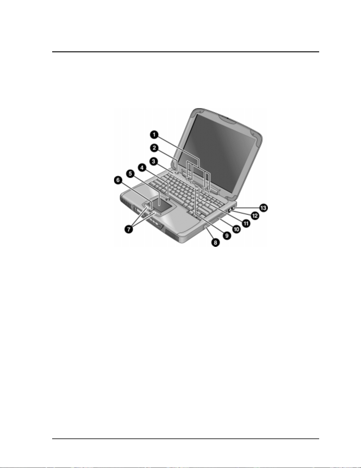
The following illustrations show the notebook’s main external features. For an exploded view of the
notebook, see page 4-2.
Figure 1-1. Top/Right View
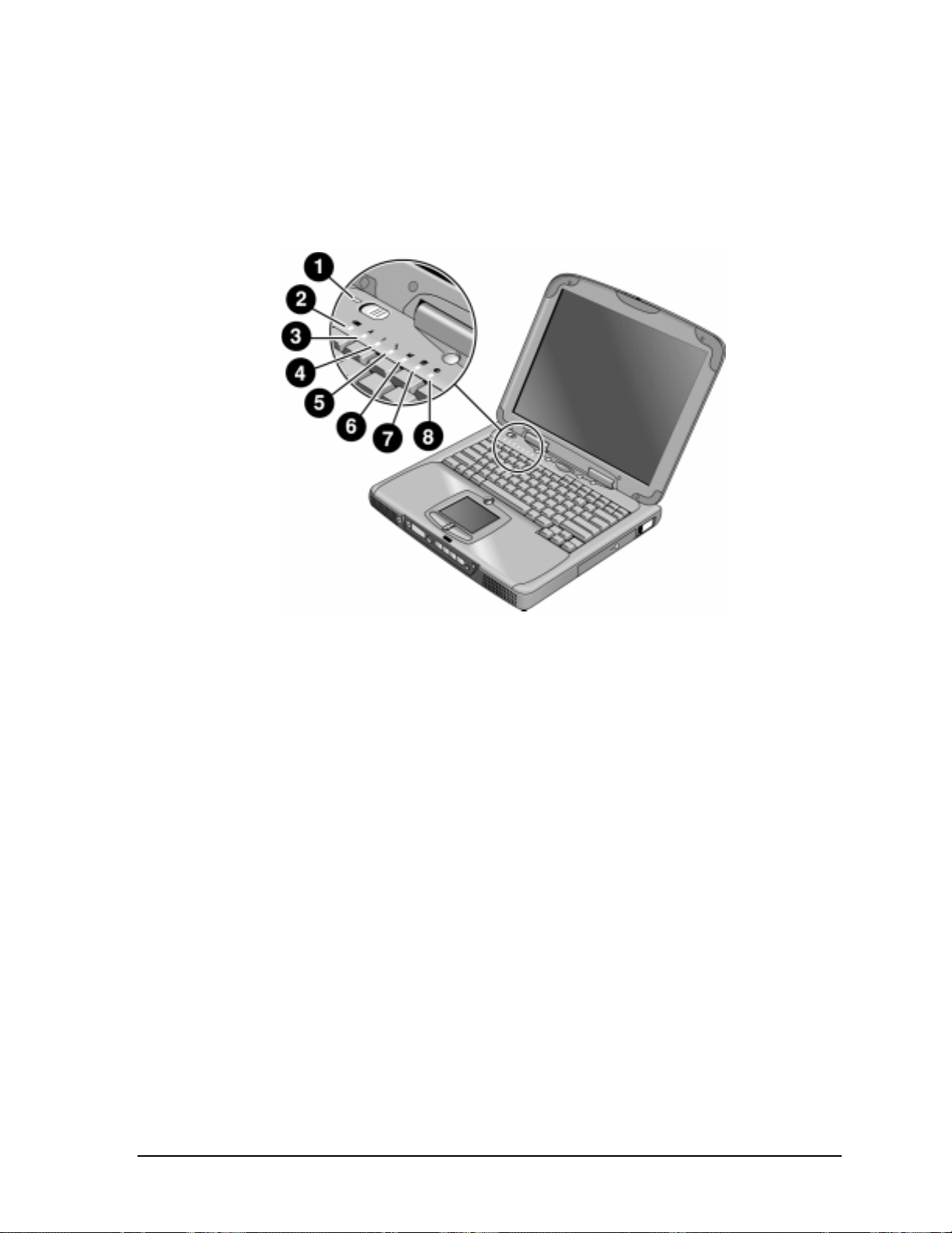
1. One-Touch buttons.
2. Power button.
3. Status lights (left to right: power status, battery
status, caps lock, num lock, scroll lock, floppy
drive access, hard drive access, CD-ROM or DVD
access. See page 1-7).
4. Pad Lock touch pad on/off button.
5. Touch pad (pointing device).
6. Scroll up/down toggle.
7. Click buttons.
8. CD-ROM or DVD drive.
9. Built-in microphone.
10. CD-ROM or DVD eject button.
11. Standby button (blue). Suspends and resumes
operation.
12. Modem port (on certain models).
13. LAN port (on certain models).
HP OmniBook XE3 Product Information 1-3
Page 13
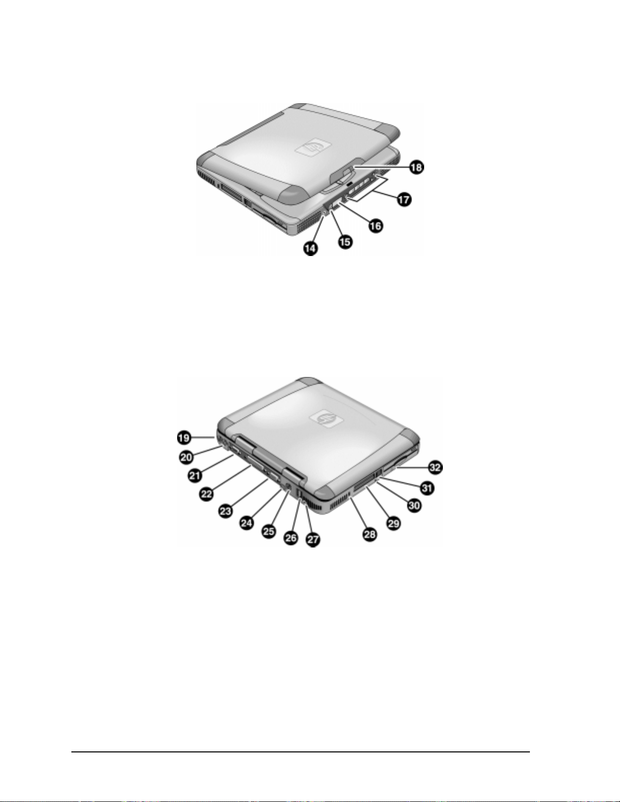
Figure 1-2. Front View
14. Headphone jack.
15. Status panel mode select button.
16. Status panel.
Figure 1-3. Rear/Left View
19. AC adapter jack.
20. PS/2 port (external mouse or keyboard).
21. Serial port.
22. Parallel port.
23. VGA port (external monitor).
24. Infrared port.
25. TV output port.
17. Multimedia buttons.
18. Latch (to open display).
26. Two USB ports.
27. Microphone jack.
28. Kensington lock slot (security connector).
29. PC card slots (upper and lower).
30. System-off switch (for resetting notebook).
31. PC card eject buttons.
32. Floppy disk drive.
1-4 Product Information HP OmniBook XE3
Page 14
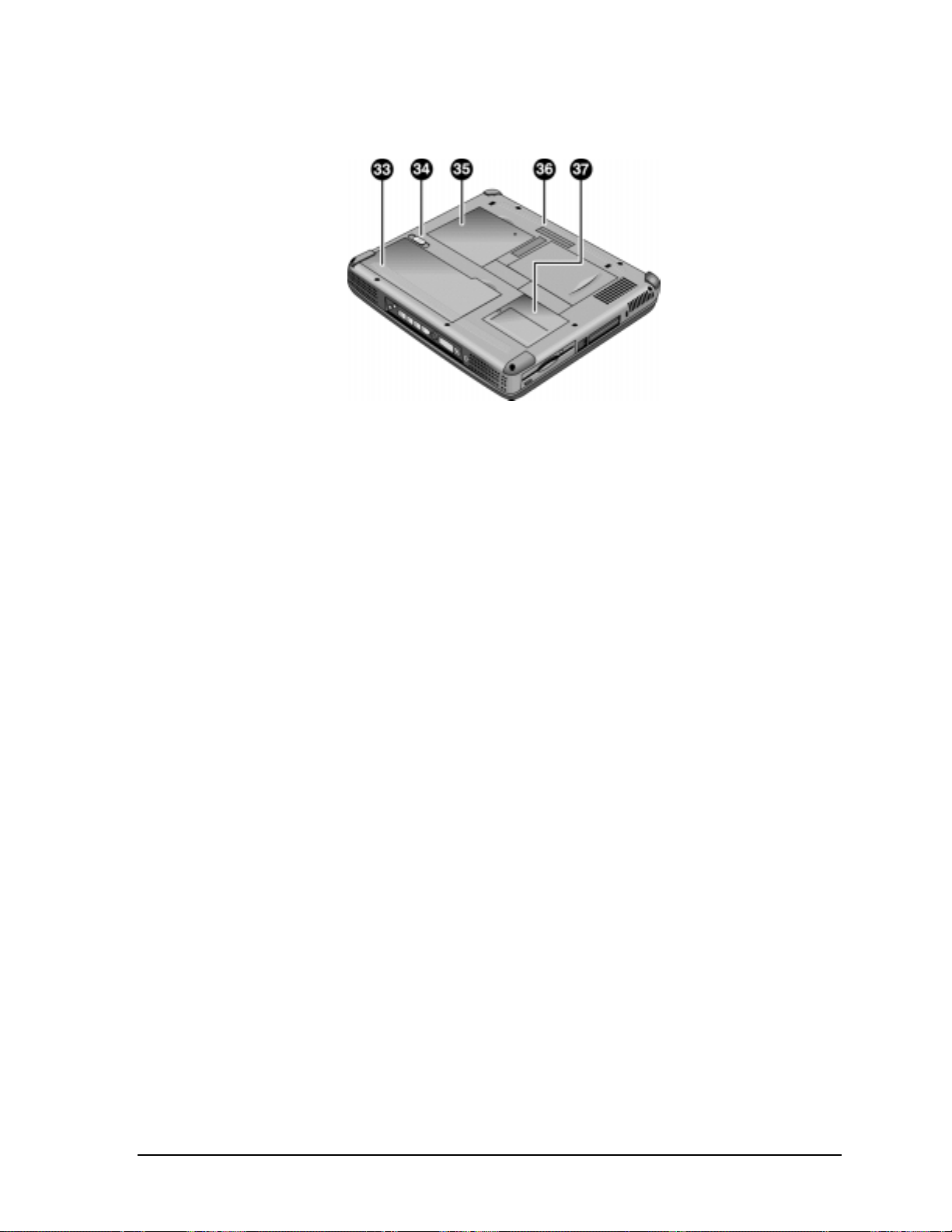
Figure 1-4. Bottom View
33. Battery.
34. Battery latch.
35. SDRAM cover.
36. Port replicator (docking) connector.
37. Mini-PCI card cover.
HP OmniBook XE3 Product Information 1-5
Page 15

Operation
This section gives an overview of the notebook’s operation.
Turning the Notebook On and Off
You can start and stop the notebook using its power button or blue standby button. However, at times
you may want to use certain methods to start or stop the notebook—depending on power
considerations, types of active connections, and start-up time.
Table 1-1. Activating Power Modes
Power mode To enter this mode To turn on again
Display-off mode
(Power status LED stays green.)
Saves minimal power.
Turns off display and hard disk.
Restarts quickly.
Maintains network connections.
Standby mode
(Power status LED turns amber.)
Saves significant power.
Turns off display, hard drive, and other
components.
Maintains current session in SDRAM.
Restarts quickly.
Restores network connections.
Hibernate mode
(Power status LED turns off.)
Saves maximum power.
Saves current session to disk, then shuts down.
Restores network connections.
Shut down (off)
(Power status LED turns off.)
Saves maximum power.
Turns off without saving current session.
At startup, resets everything, starts a new session,
and restores network connections with mini-PCI
card, and with some PCMCIA cards.
Allow timeout. Press any key or
move a pointing
device to restore
the display (“Instant
On”).
Press the blue standby button
–or–
click Start, Shutdown, Standby
–or–
allow timeout (Windows 98 only).
Press Fn+F12
–or–
Click Start, Shut Down, Hibernate
(Windows 2000 only)
–or–
allow timeout (Windows 98 only).
Click Start, Shut Down, Shut down
(recommended)
–or–
slide the power button.
Press the blue
standby button to
display your current
session (“InstantOn”).
Press the blue
standby button to
restart and restore
your previous
session.
Press the blue
standby button to
restart with a new
session.
1-6 Product Information HP OmniBook XE3
Page 16
Checking the Notebook’s Status
The notebook’s status lights—located above the keyboard—report power and battery status, keyboard
status, and drive activity.
Figure 1-5. Status Lights
1. Power status.
2. Battery status.
3. Caps lock.
4. Num lock.
5. Scroll lock.
6. Floppy disk drive activity.
7. Hard disk drive activity.
8. CD-ROM or DVD drive activity.
HP OmniBook XE3 Product Information 1-7
Page 17
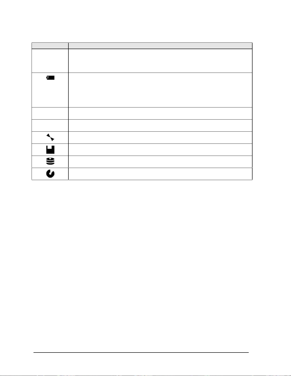
Indicator Meaning
LED next to
power button
A
1
Power status
Green: notebook is on.
Amber: notebook is in Standby mode.
No light: notebook is off or in Hibernate mode.
Battery status
Green: The AC adapter is connected and the battery is fully charged.
Amber: The AC adapter is connected and the battery is charging.
Red. The AC adapter is connected and the battery has a fault.
Off: The AC adapter is not connected, or the adapter is connected but the battery is
missing.
Caps Lock
Caps Lock is active.
Num Lock
Num Lock is active. (The Keypad Lock must also be on to use the embedded keypad.)
Scroll Lock
Scroll Lock is active.
Floppy disk drive activity
Green: notebook is accessing the floppy disk drive.
Hard disk drive activity
Green: notebook is accessing the hard disk drive.
CD-ROM or DVD drive activity
Green: notebook is accessing the CD-ROM or DVD drive.
Table 1-1. Status Lights
In addition, the status panel on the front of the notebook provides CD playback status and other
system information. For details, see the section “Status panel” in the notebook’s Reference Guide.
1-8 Product Information HP OmniBook XE3
Page 18

Using Fn Hot Keys
The combination of the Fn key plus another key creates a hot key—a shortcut key sequence—for
various system controls. To use a hot key, press and hold Fn, press the appropriate second key, then
release both keys.
External keyboards support only Fn+F5, Fn+F7, and Fn+F12. To use these, press and hold left
CTRL+left ALT, press the appropriate second key, then release both keys.
Table 1-1. Fn Hot Keys
Hot Key Effect
Fn+F1 Decreases the display brightness.
Fn+F2 Increases the display brightness.
Fn+F5 Toggles among the built-in display, an external display, and simultaneous display on
both.
Fn+F7 Mutes the notebook’s speakers.
Fn+F8 Toggles the built-in numeric keypad on and off. Does not affect an external keyboard. If
Num Lock is on, the numeric functions are active; otherwise, cursor control is active.
Fn+F12 Enters Hibernate mode (Windows 2000 only).
Fn+NumLock Toggles Scroll Lock on and off (except on external keyboards).
Fn+Up arrow Increases sound volume (except on external keyboards).
Fn+Down arrow Decreases sound volume (except on external keyboards).
HP OmniBook XE3 Product Information 1-9
Page 19

Resetting the Notebook
Occasionally, Windows or the notebook may stop responding, so that you cannot turn the notebook
off. If this happens, try the following in the order listed:
• If possible, shut down Windows: press CTRL+ALT+DEL, then click Shut Down. Press the blue
standby button to restart.
• Slide and hold the power button for about four seconds, until the display shuts down, then press
the blue standby button to restart.
• Insert a straightened paper clip into the system-off switch on the left side of the notebook
(beneath the PC card eject buttons), then press the blue standby button to restart.
Figure 1-6. Resetting the Notebook
Note
To boot from a CD-ROM or DVD drive in the module bay, insert a bootable CD (such as the
Recovery CD,
appear, then select the CD-ROM/DVD drive as the temporary boot device.
1-10 Product Information HP OmniBook XE3
) into the drive, then restart. Press ESC twice when the HP logo and prompt
Page 20

Using the CD-ROM or DVD Player
The multimedia buttons on the front of the notebook control the CD-ROM/DVD player, and work in
much the same way as do the controls of a standalone CD-ROM or DVD player. The CD-ROM/DVD
player operates whether the notebook is on, off, or in standby or hibernate mode. (When the notebook
is on, the volume control buttons also govern the volume for most other audio applications.)
If the notebook is off or in standby or hibernate mode, slide the multimedia power switch to the left to
activate the player. For details about using the CD-ROM/DVD player, see the notebook’s Reference
Guide.
Figure 1-7. Multimedia Buttons
1. Multimedia power (use only when notebook is
turned off or in standby or hibernate mode).
2. Previous track button.
3. Play/pause button.
4. Stop button (when notebook is on).
Stop/eject (when notebook is off).
5. Next track button.
6. Volume control down button.
7. Volume control up button.
HP OmniBook XE3 Product Information 1-11
Page 21

Specifications
The following tables list the specifications for the notebook and its accessories. These are subject to
change: for the latest versions, see the HP Notebook web site, www.hp.com/notebooks (in Europe:
www.europe.hp.com/notebooks).
Hardware Specifications
Table 1-1. XE3 Series Hardware Specifications
Dimensions 14.1/12.1-in display: 331 × 272.3 × 40.5 mm (13.03 × 10.72 × 1.59 in).
15/13-in display: 331 × 272.3 × 42.0 mm (13.03 × 10.72 × 1.65 in).
Weight 3.0–3.4 kg (6.7–.7.4 lb), depending on configuration.
Processor Intel Pentium III 500/550/600/650/700/750/800 MHz by µPGA2 with SpeedStep.
Intel Celeron 500/550/600/650/700 MHz by µPGA2.
100-MHz FSB.
Display 800 x 600 SVGA TFT 12.1-in LCD.
1024 x 768 XGA TFT 13-in LCD.
1024 x 768 XGA TFT 14.1-in LCD.
1024 x 768 XGA TFT 15-in LCD.
Graphics Controller S3 Savage/IX:
– Integrated 4 MB SGRAM.
– Supports AGP 2x mode.
– 128-bit, single-cycle 3D architecture.
– Simultaneous LCD/CRT and LCD/CRT/TV capability.
– Optimized hardware motion compensation.
– New high-performance, 128-bit 2D engine.
– Integrated single-channel 110-MHz LVDS interface.
– Integrated NTSC/PAL encoder.
Chip Set Intel 440ZXM-100.
SDRAM 100 MHz SDRAM (PC100).
No SDRAM on board.
Two 1.25-in. slots for expansion up to 256 MB, using two 128-MB SODIMM modules
(144 pin, 3.3 V).
Power Battery: rechargeable 9-cell:
– Lithium ion: 11.1 V, 5400 mAh, 18650 size.
– Nickel metal hydride: 10.8 V, 4000 mAh, 17670 size.
– Operating time: up to 3.3 hours typical (varies with configuration and usage).
– Recharge time: 2.2 hours.
– Standby/resume capability.
– Smart pack, SM bus.
AC adapter: Universal 60-watt, 100-240 Vac (50/60 Hz) input, 19 Vdc output.
Mass Storage Hard disk drive:
– 5 or 10 GB, PCI Bus Master Enhanced IDE.
– 9.5 mm, 2.5-in.
– Supports Ultra DMA/33.
Floppy disk drive: 1.44-MB, 12.7 mm, 3-mode module.
CD-ROM/DVD drive: 24x CD-ROM or 4x CD-RW, 12.7 mm module.
1-12 Product Information HP OmniBook XE3
Page 22

Keyboard and
Pointing Device
Audio System ESS Allegro (1988):
CD Player OZ-163 controller. CD can play while notebook is off.
Communications LAN:
Input/Output Super I/O controller: SMC 869.
PCMCIA TI 1420: two slots
Options 32/64/128 MB PC-100 SODIMM: 3.3V, 144-pin, SDRAM.
Keyboard:
– 87-/88-/90-key touch-type QWERTY keyboard with 101/102 key emulation.
– Embedded numeric keypad, 12 function (Fn) keys.
– Spill-resistant.
– NS 87570 keyboard controller.
Pointing device: touch pad with on/off and scroll up/down buttons.
– Integrated AC’97 CODEC.
– HSP modem interface via MC’97 link.
– Support wake-up on ring.
Modem CODEC ESS 2828 on mini-PCI slot.
Stereo sound via two built-in speakers.
Built-in microphone.
Microphone and headphone jacks.
– Transmission rate: 10 or 100 Mbps based on Auto-Negotiation.
– Data standard: supports Category 3 (10BaseT/100BaseT) and Category 5 (100
Base TX) media coupler.
– 10BASE-T/100BASE-TX: 10BASE-T/100BASE-TX MAC+PHY integrated controller
solution.
– Power management: supports remote power-up using Wake on LAN (WOL)
technology and Deep power-down mode support.
Modem:
– Data modem standard: supports V.90, V.34, V.32bis, V.32, V.22bis, V.22, V.23,
and V.21; Bell 212A and 103.
– Error correction: V.42 LAPM, and MNP 2-4 error correction.
– Data compression: V.42bis and MNP 5 data compression.
– Fax modem standard: send/receive rates up to 14400 bps, V.17, V.29, V.27ter,
and V.21 channel 2.
– Power management: supports ACPI Power Management and wake up on ring.
Serial port: 9-pin (RS232), 115,200-bps (16550 UART).
Parallel port: 25-pin, bi-directional, high-speed, with ECP/EPP capability.
PS/2 port: 6-pin keyboard/keypad/mouse port (Y adapter compatible).
VGA video out: 15-pin, with hot plug/unplug CRT-detect. (Resolution from 640 × 480
up to 1024 × 768, depending on available SDRAM.)
Two universal serial bus (USB) ports.
One IrDA-compliant fast infrared (FIR) port.
Docking port for simple port replicator.
DC-in jack.
Composite TV out: supports LCD, CRT, LCD/CRT, LCD/TV.
– PC Card 95 supports one type III or two type II sockets.
– Complies with PCI power management, ACPT 2.0, PCI local bus spec. Rev. 2.2.
– 3.3-volt core logic with universal PCI interface, compatible with 3.3/5-volt PCA
signaling environment.
– Supports burst transfers to maximize data throughput on both PCI buses.
– Supports parallel PCI interrupts, parallel ISA IRQ with parallel PCI interrupts, serial
ISA IRQ with parallel PCI interrupts, and serial ISA IRQ with PCI interrupts.
– Can wake up from D3 (cold).
– No Zoomed Video support.
Simple port replicator.
Mini-PCI modem, supporting wake-up on Ring# from D3 (cold) with AC-in.
Mini-PCI modem/LAN combo, supporting wake-up on Ring# & PME# from D3 (cold)
with AC-in.
HP OmniBook XE3 Product Information 1-13
Page 23

Mechanical Features Kensington MicroSaver lock slot.
Continuously variable-speed fan.
Standards PC99, ACPI.
Environmental Limits
Operating temperature: 0 to 40 °C (32 to 104 °F).
Operating humidity: 10 to 90 percent RH without condensation.
Operating altitude: up to 3050 m (10,000 ft).
Storage temperature: –20 to 65 °C (–4 to 149 °F).
Storage altitude: up to 12,200 m (40,000 ft).
Mean time between failure: 20,000 hours.
Software Specifications
Table 1-1. XE3 Series Software Specifications
Operating Software Microsoft Windows 98SE, 2000, or Millennium Edition (all in ACPI mode).
512KB flash BIOS ROM (PLCC type with socket for B-Test only).
Supports standby to RAM or hard disk.
Hot keys for system control.
Password protection.
Auto-configuration when using simple port replicator.
PC99 ready with Plug-and-Play.
Keyboard BIOS flashable.
ACPI 1.0b compatible.
Smart battery support.
DMI EEPROM (2 KB) extension.
Bootable devices; FDD, HDD, CD-ROM/DVD.
Applications Adobe Acrobat Reader.
MusicMatch MP3 software (certain models only).
DVD player (models with DVD only).
One-Touch Button software.
Fax software (included in Windows 2000).
Virus protection software.
For additional information about the notebook’s software, see the HP Notes.
1-14 Product Information HP OmniBook XE3
Page 24

System Resources
The following tables list the default values for the notebook’s system resources. Use the BIOS Setup
utility (see page 3-29) to view all available port and audio device configurations in the System
Devices menu.
The tables in this section show typical resource usage as set up by the notebook’s BIOS. Plug-andplay operating systems, drivers, and BIOS Setup settings may change some of the entries.
Table 1-1. System Interrupts
0 System timer
1 Keyboard
2 Cascade from secondary interrupt controller
3 Free
4 COM1 (serial port)
5 Audio
6 Floppy disk drive
7 LPT1 (ECP parallel port)
8 Real-time clock
9 SCI
10 PCI IRQ (shared by all PCI devices)
11 Free (or MIDI if enabled)
12 Touch pad, PS/2 mouse
13 Numeric coprocessor
14 Internal hard disk drive (primary IDE controller)
15 Internal CD-ROM drive (secondary IDE controller)
Table 1-2. System Memory
00000–9FFFF System memory
A0000–BFFFF Video
C0000–CFFFF Video BIOS
D0000–DBFFF Free: can be used for upper memory blocks
(UMBs) or PC card memory windows
DC000–FFFF System BIOS
HP OmniBook XE3 Product Information 1-15
Page 25

Table 1-3. System Input/Output Addresses (100-3FF)
170–177 Internal CD-ROM drive (secondary IDE controller)
1F0–1F7 Internal hard disk drive (primary IDE controller)
220–22F DOS games (FM decoding)
376 Internal CD-ROM drive (secondary IDE controller)
378–37F LPT1 (printer port)
388–38B DOS games (FM decoding)
3B0–3BB VGA adapter
3C0–3DF VGA adapter
3E0–3E1 PCMCIA controller
3F0–3F5 Floppy disk drive controller
3F6 Internal hard disk drive (primary IDE controller)
3F7 Floppy disk drive controller
3F8–3FF COM1 (serial port)
Table 1-4. DMA Channels
0 Free
1 Free
2 Floppy disk drive
3 LPT1 (ECP parallel port)
4 Cascade from secondary DMA controller
5 Free
6 Free
7 Free
1-16 Product Information HP OmniBook XE3
Page 26

Table 1-5. XE3 Series Accessories
Accessory Description
Memory
F1456B 32-MB SDRAM PC-100 expansion module
F1457B 64-MB SDRAM PC-100 expansion module
F1622B 128-MB SDRAM PC-100 expansion module
Power Options
F1454A AC adapter (60-watt)
F1781A Ultra Slimline AC adapter (60-watt)
F1455A Auto/airline AC adapter (75-watt)
F2024A LiIon battery (9 cell)
Adapters
F1469A PS/2 “Y” adapter
PC Cards
F1623A 10/100-Mbps Ethernet +56-Kbps modem PC Card by Xircom
F1625A 56-Kbps global modem PC Card by Xircom
F1626A 10/100 LAN CardBus PC Card by 3Com
F1626B 10/100 LAN CardBus PC Card by 3Com
F1627A 56-Kbps US modem PC Card by Xircom
F1643A RealPort 10/100-Mbps Ethernet + 56-Kbps modem PC Card by Xircom
F1985A USB-NIC Ethernet adapter by 3Com
Docks
F2025A Simple port replicator
Wireless Accessories
F2135A Wireless LAN access point
F2136A Wireless LAN PC Card
F2137A Wireless LAN PCI adapter
F2138A Wireless card
Security Accessories
F1645A Kensington MicroSaver Notebook Security System
F1747A Port Defcon 1 Notebook Security System
F1611C Mobile ProtectTools 2000 Smart Card Kit (128-bit version for U.S. and
Canada only)
F1612C Mobile ProtectTools 2000 Smart Card Kit (40-bit version for outside U.S. and
Canada)
HP OmniBook XE3 Product Information 1-17
Page 27

Internal Design
y
The motherboard PCA is the central component of the notebook’s design, and plays a role in virtually
all system functions. The CPU module and most other subsystems connect to the motherboard.
The following figure shows the connections among the notebook’s replaceable electronic modules. In
addition, the table on page 1-18 lists the roles that the replaceable modules play in each of the
notebook’s functional subsystems.
Display
Assembly
CPU Module Video PCA Switchboard PCA
Top Case
(speakers, touch
pad, click buttons)
Heatsink/fan
assembl
PCMCIA
Cards
Motherboard PCA
PCMCIA
Sockets (2)
Mini-PCI
P
CD-ROM or DVD
Module
A
Floppy Disk
Drive
Earphone
PCA
Hard Disk
Drive
CD Player
PCA
Keyboard
Battery
Figure 1-8. Replaceable Module Diagram
SDRAM
Module
1-18 Product Information HP OmniBook XE3
Page 28

Table 1-1. Functional Structure
Function Components Used Component Roles
Bootup CPU module
Motherboard
Floppy disk module
Hard disk drive
Processor CPU module
Motherboard
Memory Motherboard
SDRAM module
Video PCA
Power Battery
Motherboard
Switchboard PCA
AC adapter
Display Motherboard
Display assembly
Video PCA
Hard disk Motherboard
Hard disk drive
Floppy drive Motherboard
Floppy disk module
Keyboard Motherboard
Keyboard
Touch pad Motherboard
Top case
Audio Motherboard
Switchboard PCA
Headphone PCA
Top case
Status Motherboard
Switchboard PCA
CD player PCA
Serial Motherboard I/O controller, serial connector.
Parallel Motherboard I/O controller, parallel connector.
Infrared Motherboard I/O controller, infrared transmitter/receiver.
PS/2 port Motherboard Keyboard controller, PS/2 connector.
USB Motherboard Bus controller, USB connectors.
Docking port Motherboard Docking logic, docking connector.
PCMCIA Motherboard
PCMCIA sockets
Main processor.
Primary system circuitry.
First source of disk-based startup code.
Second source of disk-based startup code.
Main processor, numeric data processor, L1 and L2 cache.
Primary system circuitry.
No onboard RAM.
Changeable RAM (2 slots).
Video RAM.
Power storage.
Power control circuitry, AC adapter socket, lid switch, system-off switch,
power supply.
Power button, standby button.
AC-to-DC converter.
Video controller.
Display output, backlight, power converter for backlight.
Display drivers, LVDS processing, display/graphics controller, video
RAM.
Hard disk controller.
Hard disk mechanism.
I/O controller, floppy connector.
Floppy disk mechanism.
Keyboard controller, keyboard BIOS.
Key switches.
Keyboard BIOS.
Touch pad sensor, click buttons, controller (PS/2 output).
Audio controller, audio decoder, speaker amplifier, external microphone
jack.
Microphone.
Earphone amplifier.
Speakers.
LED circuitry, keyboard controller.
Status LEDs.
CD-ROM/DVD status display.
PCMCIA controller.
PCMCIA connectors.
HP OmniBook XE3 Product Information 1-19
Page 29

Page 30

This chapter tells you how to remove and replace the notebook’s removable components and
assemblies. The items marked by
• Battery (page 2-3).
• Carrier, hard disk drive (page 2-14).
Case, bottom (page 2-34).
Case, top (page 2-20).
• Cover, keyboard (page 2-9).
• Cover, mini-PCI (page 2-16).
• Cover, SDRAM (page 2-16).
• Covers, screw (page 2-16).
Display assembly (page 2-17).
Doors, docking (page 2-38).
Doors, PCMCIA (page 2-39).
Drive, CD-ROM/DVD (page 2-33).
Drive, floppy disk (page 2-31).
• in the following table are user-replaceable.
Table 2-1. Removal Cross-Reference
Heatsink assembly (with fan) (page 2-27).
• Keyboard (page 2-11).
Module, CPU (page 2-29).
• Module, SDRAM (page 2-5).
PCA, CD player (page 2-22).
PCA, headphone (page 2-41).
• PCA, mini-PCI (page 2-7).
PCA, motherboard (page 2-34).
PCA, switchboard (page 2-41).
PCA, video (page 2-25).
Plate, CPU support (page 2-42).
Saddle, hinge set (page 2-22).
Socket, PCMCIA (page 2-42).
• Drive, hard disk assembly (page 2-13).
Caution
Always provide proper grounding when performing repairs. Without proper
grounding, an electrostatic discharge can damage the notebook and its
components.
Notes
To reassemble a component, perform the removal procedure in reverse order. Any special notes
required for reassembly are included at the end of each section.
Symbols like this throughout this chapter show approximate full-size screw outlines. You can
use these to verify the sizes of screws before you install them. Installing a wrong-size screw can
damage the notebook. (The symbol at the left represents an M2.5×5mm T-head screw.)
HP OmniBook XE3 Removal and Replacement 2-1
Page 31

Disassembly Flowchart
y
The following diagram shows the general “path” you will use in disassembling the notebook to access
any particular component.
Start
Battery, AC adapter,
SDRAM modules, mini-PCI card
Keyboard cover
Only if not removing
motherboard
or bottom case
If removing only
heatsink assembly
or CPU module
Keyboard
Hard disk drive assembl
Display assembly
Top case assembly
Hinge saddle set
• CD-ROM/DVD drive assembly
• Video PCA
• Floppy disk drive assembly
• Headphone PCA
Heatsink assembly (with fan)
Switchboard PCA
(also remove if removing
motherboard or bottom
case assembly)
CD player PCA
CPU module
Motherboard or
bottom case
• CPU support plate
• Docking doors
• PCMCIA doors
Figure 2-1. Disassembly Flow
2-2 Removal and Replacement HP OmniBook XE3
Page 32

Table 2-1. Required Equipment
• Small Phillips screwdriver, preferably magnetized.
• Small flat-blade screwdriver.
• 5mm hexagonal socket screwdriver.
Table 2-2. Recommended Screw Torques
Screw Thread Size Torque (cm-kgf) Torque (in-lbf)
M2.5 (2–11 mm long) 3.0 – 3.5 2.6 – 3.0
M2.5 (12–19 mm long) 2.5 – 3.0 2.2 – 2.6
M3 3.0 – 3.5 2.6 – 3.0
NOTES
HP OmniBook XE3 Removal and Replacement 2-3
Page 33

Removing the Battery
(User-Replaceable)
Required Equipment
• None.
Removal Procedure
• Slide the battery’s release latch, then lift the battery out of its compartment.
Figure 2-2. Removing the Battery
Reassembly Notes
• Insert the front (rounded) end of the battery into the battery compartment, and lower the back end
in until it clicks into place.
2-4 Removal and Replacement HP OmniBook XE3
Page 34

Removing an SDRAM Module
(User-Replaceable)
The notebook has no SDRAM on its motherboard, but has slots for two SDRAM modules. One slot
contains an SDRAM module installed at the factory.
See Table 4-2 on page 4-5 for a listing of replacement SDRAM modules and part numbers.
Caution
Provide proper grounding and handle the SDRAM module only by its edges, or you could damage
the module through electrostatic discharge.
Required Equipment
• Small Phillips screwdriver.
Removal Procedure
1. Unplug the AC adapter, if present, and remove the battery.
2. On the bottom of the notebook, loosen both screws holding the SDRAM cover (the cover retains
the screws), and remove the cover.
Figure 2-3. Removing the SDRAM Cover
HP OmniBook XE3 Removal and Replacement 2-5
Page 35
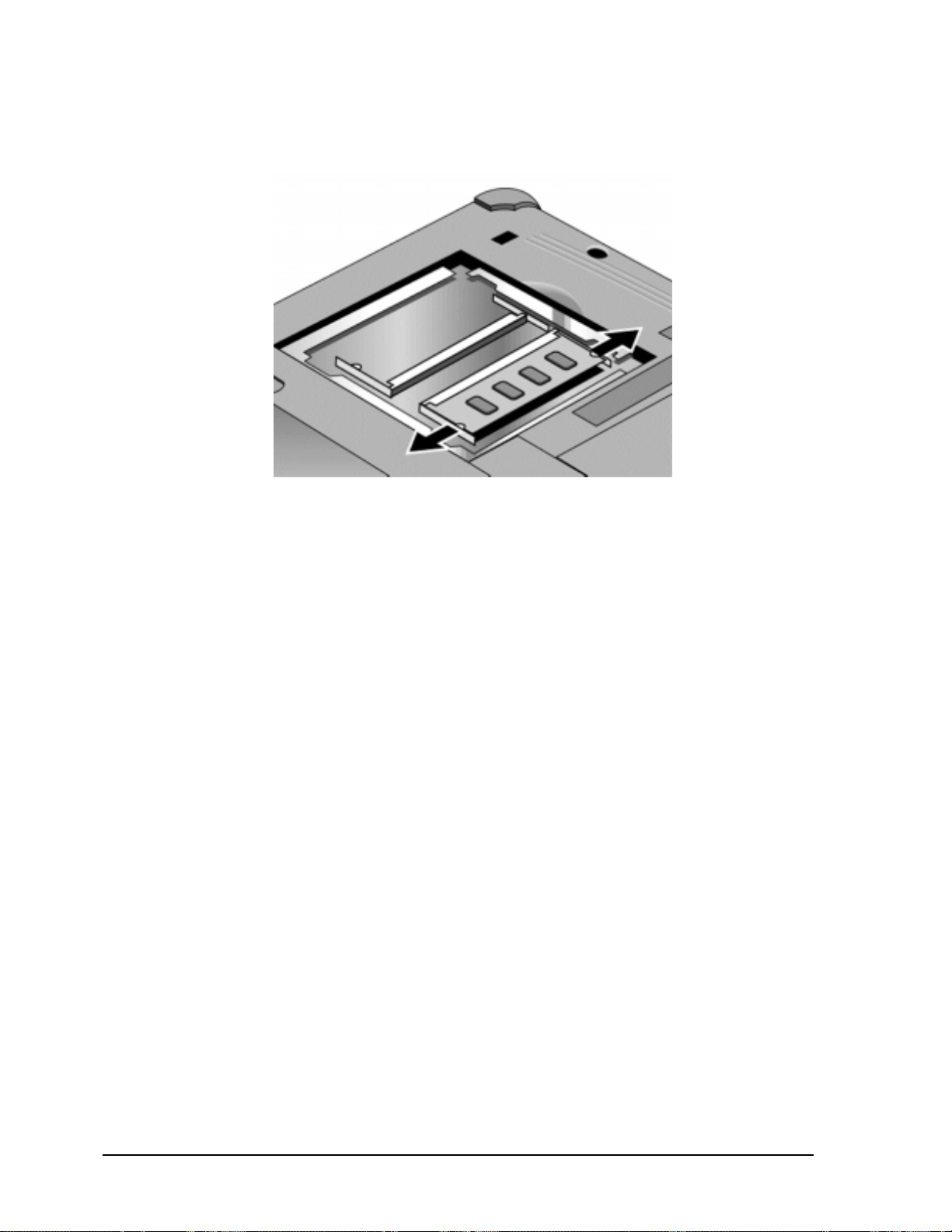
3. Press outward to release the latches at the sides of the SDRAM module, so the free edge of the
module pops up.
Figure 2-4. Removing an SDRAM Module
4. Pull the module out of the connector.
Reassembly Notes
• Gently press the SDRAM module into the connector at an angle of about 30°, until it is fully
inserted. Then press down on both sides of the module until the latches snap closed.
2-6 Removal and Replacement HP OmniBook XE3
Page 36

Removing the Mini-PCI PCA
(User-Replaceable)
Certain notebook models include a mini-PCI PCA that contains either a modem or modem/LAN. See
Table 4-2 on page 4-5 for a listing of replacement PCAs and part numbers.
Caution
Provide proper grounding and handle the PCA only by its edges, or you could damage it through
electrostatic discharge.
Required Equipment
• Small Phillips screwdriver.
Removal Procedure
1. Unplug the AC adapter, if present, and remove the battery.
2. Loosen the screw holding the mini-PCI cover (the cover retains the screw), and remove the cover.
3. Press outward to release the latches at the sides of the PCA, so that its free edge pops up.
4. Disconnect the cable (modem models only) or cables (modem/LAN models only) from the PCA.
5. Gently pull the PCA out of its connector.
HP OmniBook XE3 Removal and Replacement 2-7
Page 37
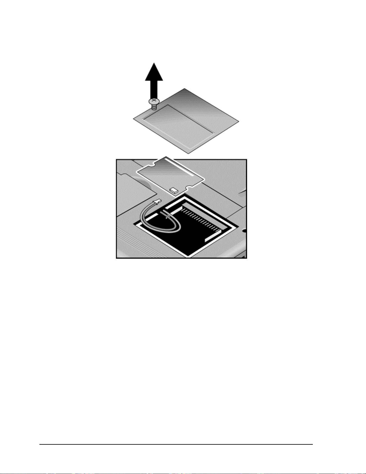
Figure 2-5. Removing the Mini-PCI Card
Reassembly Notes
• Reattach the cable (modem models only) or cables (modem/LAN models only) to the PCA, and
tuck them into the compartment.
• Gently press the mini-PCI card into the connector at an angle of about 30°, until it is fully inserted.
Then press down on both sides of the card until the latches snap closed.
2-8 Removal and Replacement HP OmniBook XE3
Page 38

Removing the Keyboard Cover (with Hinge Covers)
(2)
(User-Replaceable)
Required Equipment
• Small Phillips screwdriver.
• Small flat-blade screwdriver.
Removal Procedure
1. Unplug the AC adapter, if present, and remove the battery.
2. Close the display, and remove both screws from the backs of the hinge covers.
Screws,
M2.5x4 mm
Figure 2-6. Removing the Keyboard Cover Retaining Screws
3. Open the notebook’s display 180°, so that it lays flat.
4. Use the flat-blade screwdriver to carefully pry up the inside edges of the hinge covers until the
cover pops loose, then lift the cover off.
HP OmniBook XE3 Removal and Replacement 2-9
Page 39

Figure 2-7. Removing the Keyboard Cover
Reassembly Notes
• Tuck the display cables into the notch just to the right of the left display hinge.
• Hold the cover by the hinges and snap it into place. Note that the cover is held in place partly by
tabs at the left and center of its bottom edge, and at its upper left and right corners. Make sure these
tabs snap back into place when reinstalling the cover.
2-10 Removal and Replacement HP OmniBook XE3
Page 40
Removing the Keyboard
(User-Replaceable)
Required Equipment
• Small Phillips screwdriver.
• Small flat-head screwdriver.
Removal Procedure
1. Unplug the AC adapter, if present, and remove the battery.
2. Remove the keyboard cover (page 2-9).
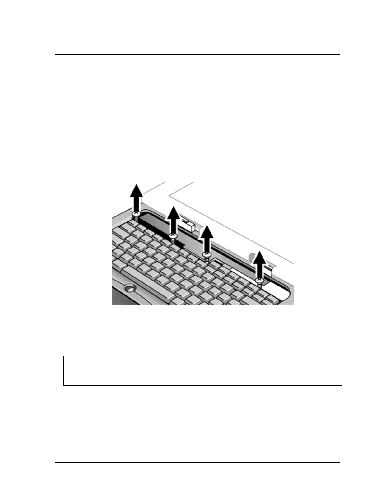
3. Loosen the four retaining screws along the top of the keyboard (the keyboard retains the screws).
Figure 2-8. Loosening the Keyboard Retaining Screws
4. Raise the top of the keyboard, then lift the keyboard up and out of the notebook. Be careful not to
pull on the ribbon cable connecting the keyboard to the notebook.
Caution
Be careful not to touch the heatsink until it has cooled. It could be hot if the notebook was running
recently.
5. Lay the keyboard face down on the top case, forward of its normal position, and disconnect the
ribbon cable from the motherboard.
HP OmniBook XE3 Removal and Replacement 2-11
Page 41
Keyboard
ribbon cable
Figure 2-9. Disconnecting the Keyboard Cable
Reassembly Notes
• Lay the keyboard face down on the top case forward of its normal position, then reconnect the
ribbon cable.
• Slip the metal tabs on the bottom of the keyboard into their slots in the top case, then lower the
keyboard into place.
2-12 Removal and Replacement HP OmniBook XE3
Page 42

Removing the Hard Disk Drive Assembly
(User-Replaceable)
See Table 4-2 on page 4-5 for a listing of replacement hard disk drives and part numbers.
Required Equipment
• Small Phillips screwdriver.
Removal Procedure
1. Unplug the AC adapter, if present, and remove the battery.
2. Remove these additional assemblies:
• Keyboard cover (page 2-9).
• Keyboard (page 2-11).
Caution
Be careful not to touch the heatsink until it has cooled. It could be hot if the notebook was running
recently.
3. Loosen the four screws attaching the hard drive carrier to the motherboard (the carrier retains the
screws).
4. Use the strap on the hard drive to carefully pull the drive off of its connector and out of the
notebook.
Figure 2-10. Removing the Hard Disk Drive
HP OmniBook XE3 Removal and Replacement 2-13
Page 43

5. Remove all four screws from the underside of the hard drive carrier, then slide the drive back and
(2)
(2)
up out of the case.
Pin connector
Screws,
M3x6 mm
Screws,
M3x6 mm
Figure 2-11. Removing the Hard Disk Carrier
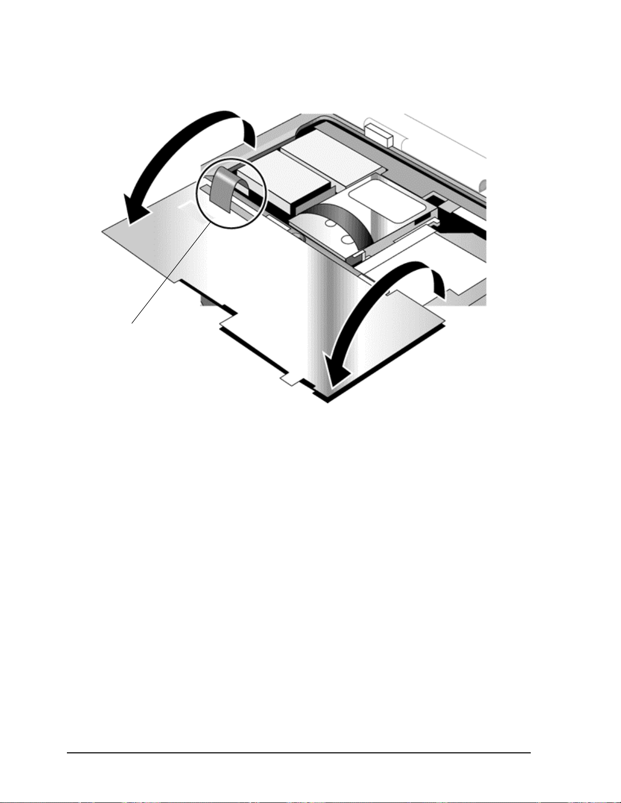
6. Carefully remove the pin connector from the end of the drive by working alternately at each side,
so that the connector slides off evenly without bending the connector pins.
Reassembly Notes
• Carefully put the pin connector back onto the pins on the end of the new hard drive. Work at each
end alternately so that the connector slides on evenly without bending the connector pins.
• Be careful not to trap the heatsink and keyboard cables beneath the hard drive.
2-14 Removal and Replacement HP OmniBook XE3
Page 44

Recovering and Reinstalling Software
You can use the Recovery CD to recover an original build or reinstall the HP custom software. To
recover a specific application, see “To recover an application” in the Reference Guide.
The Recovery CD provides all HP notebook–specific Windows drivers; these drivers are in the
following directories:
• On the hard drive, under c:\hp\drivers.
• On the Recovery CD, under \hp\drivers.
• On the HP notebook web site at http://www.hp.com/notebooks. This web site contains the latest
software drivers.
To recover the factory software installation
The following procedure describes how to recover the notebook’s original Windows software and
operating system.
This process can take about 10 or 15 minutes. Do not interrupt the process or unplug the AC adapter
before the process is complete, or you will have to begin again.
Caution
This procedure formats the hard disk drive, which erases all data on the drive. After formatting,
you must reinstall any applications.
1. Back up all data from the hard disk.
2. Connect the AC adapter to the notebook.
3. Insert the Recovery CD in the notebook’s CD-ROM drive.
4. Restart the notebook. When the HP logo appears, press F2.
5. Select the CD-ROM drive as the first boot device, then restart the notebook again.
You can find more details about recovering the factory installation of Windows on the Recovery CD:
the file readme.txt is in the CD’s root directory.
Note
Windows 98 supports the FAT16 and FAT32 file systems. Windows 2000 supports the FAT16,
FAT32, and NTFS file systems.
HP OmniBook XE3 Removal and Replacement 2-15
Page 45

Replacing Small Parts
(User-Replaceable)
The user can replace the following small parts.
Table 2-1. Replacing Small Parts (User-Replaceable)
Part Replacement Procedure
Cover, mini-PCI On the bottom of the notebook, loosen the screw in the mini-PCI cover (the cover
retains the screw) and remove the cover.
Cover, SDRAM On the bottom of the notebook, loosen the screws in the SDRAM module cover (the
cover retains the screws) and remove the cover.
Covers, screw (on
display bezel)
Insert a small flat-blade screwdriver under the cover and pry it loose. To replace,
firmly press the adhesive side of the cover into the recess.
2-16 Removal and Replacement HP OmniBook XE3
Page 46

Removing the Display Assembly
(HP Authorized Service Providers Only)
Required Equipment
• Small Phillips screwdriver.
Removal Procedure
1. Unplug the AC adapter, if present, and remove the battery.
2. Remove these additional assemblies:
• Keyboard cover (page 2-9).
• Keyboard (page 2-11).
3. Remove both screws from the switchboard PCA, and carefully lift the PCA off the connector
underneath it. Be carefully not to pull on the cable attached to the PCA.
4. Disconnect the cable from the switchboard PCA, and remove the PCA from the notebook.
5. Disconnect the cable from the video PCA.
6. Remove the four flanged screws from the display hinges. This may be easier if you support the
display so that it remains approximately flat.
7. Lift the display off of the notebook.
HP OmniBook XE3 Removal and Replacement 2-17
Page 47

Screws (flanged)
M2.5x8 mm (4)
Screws,
M2.5x4 mm
Figure 2-12. Removing the Display
Reassembly Notes
• While installing the hinge screws, support the display so that it remains approximately flat.
• Before installing the switchboard PCA, make sure the large display cable lies within the notch in
the hinge saddle.
• When in stalling a new display assembly, follow the procedure given in “Installing a New Display
Assembly” on the following page.
2-18 Removal and Replacement HP OmniBook XE3
Page 48

Installing a New Display Assembly
When installing a new display, you must make sure to set the DIP switches on the video PCA to match
the particular display assembly. Do this as follows.
Caution
Setting the DIP switches improperly could damage the display assembly.
1. Find the manufacturer of the display: this is shown on a label attached to the display assembly.
2. Find the display’s manufacturer and model in the table below, and set the DIP switches on the
video PCA as shown.
Model 1 2 3 4
CPT 14.1-in TFT XGA ON OFF ON OFF
Hitachi 15.0-in TFT XGA OFF ON OFF OFF
LG 13.3-in TFT XGA ON OFF OFF ON
LG 14.1-in TFT XGA OFF ON OFF ON
LG 15.0-in TFT XGA ON ON ON OFF
Mitsubishi 12.1-in TFT SVGA ON OFF ON ON
Samsung 12.1-in TFT SVGA ON ON OFF OFF
Samsung 14.1-in TFT XGA OFF ON ON OFF
Sanyo 12.1-in TFT SVGA OFF OFF ON ON
Unipac 13.3-in TFT XGA OFF OFF ON OFF
Unipac 14.1-in TFT XGA OFF OFF OFF ON
As an example, the following figure shows the DIP switches set to OFF-ON-ON-ON:
2134
FOF
Figure 2-13. Video PCA DIP Switches
HP OmniBook XE3 Removal and Replacement 2-19
Page 49

Removing the Top Case
(HP Authorized Service Providers Only)
Required Equipment
• Small Phillips screwdriver.
Removal Procedure
1. Unplug the AC adapter, if present, and remove the battery.
2. Remove these additional assemblies:
• Keyboard cover (page 2-9).
• Keyboard (page 2-11).
• Display assembly (page 2-17).
3. Remove the eight retaining screws from the bottom case.
Screws,
M2.5x8 mm
Screws,
M2.5x8 mm
Figure 2-14. Removing the Top Case Retaining Screws
4. Disconnect the touch pad cable and speaker cable from the motherboard.
5. Remove the six retaining screws from the top case.
6. Raise the back of the top case, then gradually loosen the case, moving toward the front of the
notebook (the right rear corner may require extra care to work free).
7. Carefully lift the top cover forward and off of the notebook. Be careful not to pull on the CD
player PCA ribbon cable beneath the case.
2-20 Removal and Replacement HP OmniBook XE3
Page 50

8. Release the CD player PCA cable from the motherboard.
M2.5x4 mm
cables
Touch pad
cable
Screw,
M2.5x8 mm
Speaker
CD player
ribbon cable
Screws,
Figure 2-15. Removing the Top Case
Reassembly Notes
• Make sure the touch pad cable and speaker cable connectors are fully inserted squarely in their
sockets.
• Make sure both tabs along the front of the case snap shut.
HP OmniBook XE3 Removal and Replacement 2-21
Page 51

Removing the CD Player PCA
(HP Authorized Service Providers Only)
Required Equipment
• Small Phillips screwdriver.
Removal Procedure
1. Unplug the AC adapter, if present, and remove the battery.
2. Remove these additional assemblies:
• Keyboard cover (page 2-9).
• Keyboard (page 2-11).
• Display assembly (page 2-17).
• Top case (page 2-19).
3. Remove both standoff screws (requires a 5mm socket driver), and lift the PCA out of the top case.
CD player PCA standoff
screws, 5 mm (2)
Figure 2-16. Removing the CD Player PCA
2-22 Removal and Replacement HP OmniBook XE3
Page 52

Removing the Hinge Saddle Set
(HP Authorized Service Providers Only)
Required Equipment
• Small Phillips screwdriver.
Removal Procedure
1. Unplug the AC adapter, if present, and remove the battery.
2. Remove these additional assemblies:
• Keyboard cover (page 2-9).
• Keyboard (page 2-11).
• Display assembly (page 2-17).
• Top case (page 2-19).
3. Remove the two retaining screws from the bottom case.
Screws,
M2.5x8 mm
Figure 2-17. Removing the Hinge Saddle Retaining Screws
HP OmniBook XE3 Removal and Replacement 2-23
Page 53

4. Remove the retaining screws from the back of the notebook, just below the display hinges.
M2.5x8 mm
5. Remove both retaining screws from the hinge saddle set.
6. Lift the hinge saddle set out of the notebook. You may need to free the hinge saddle from the clip
in the bottom case near the LAN/modem ports to remove it.
Screws,
Screws,
M2.5x8 mm
Figure 2-18. Removing the Hinge Saddle
Reassembly Notes
• Make sure the posts on the underside of the hinge saddle line up with the hinge support openings in
the bottom case, and that the holes in the front ends of the saddle fit over the alignment posts in the
bottom case.
2-24 Removal and Replacement HP OmniBook XE3
Page 54

Removing the Video PCA
(HP Authorized Service Providers Only)
Required Equipment
• Small Phillips screwdriver.
Removal Procedure
1. Unplug the AC adapter, if present, and remove the battery.
2. Remove these additional assemblies:
• Keyboard cover (page 2-9).
• Keyboard (page 2-11).
• Display assembly (page 2-17).
• Top case (page 2-19).
• Hinge saddle set (page 2-23).
3. Note and record the settings of the PCA’s DIP switches.
HP OmniBook XE3 Removal and Replacement 2-25
Page 55
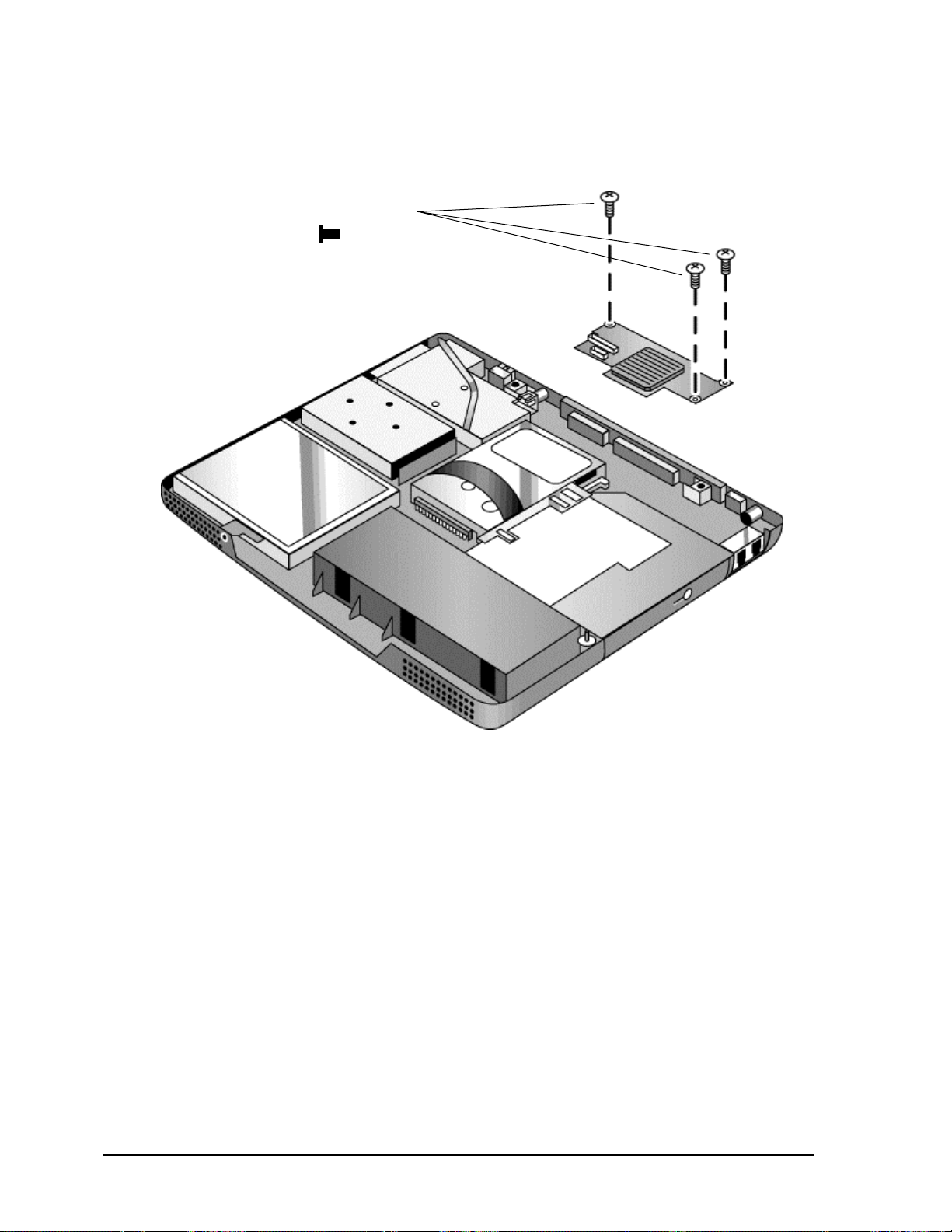
4. Remove all three retaining screws from the PCA, and carefully lift it off of the connectors
underneath it.
Screws,
M2.5x4 mm
Figure 2-19. Removing the Video PCA
Reassembly Notes
• Set the DIP switches on the new PCA to match the settings from the PCA you are replacing and
the notebook’s display type. See “Installing a New Display Assembly” on page 2-19.
2-26 Removal and Replacement HP OmniBook XE3
Page 56

Removing the Heatsink Assembly (with Fan)
(HP Authorized Service Providers Only)
Required Equipment
• Small Phillips screwdriver.
Removal Procedure
1. Unplug the AC adapter, if present, and remove the battery.
2. Remove these additional assemblies:
• Keyboard cover (page 2-9).
• Keyboard (page 2-11).
• Display assembly (page 2-17).
• Top case (page 2-19).
• Hinge saddle set (page 2-22).
3. Disconnect the fan cable from the motherboard.
4. Remove all four retaining screws (their springs are attached to them).
5. Lift the heatsink out of the notebook.
HP OmniBook XE3 Removal and Replacement 2-27
Page 57

Heatsink retaining
screws (with springs)
(4)
Figure 2-20. Removing the Heatsink Assembly
Reassembly Notes
• Make sure the fan cable is not pinned under the assembly.
• Make sure the thermal pad on the heatsink is not damaged, and replace if necessary.
2-28 Removal and Replacement HP OmniBook XE3
Page 58

Removing the CPU Module
(HP Authorized Service Providers Only)
See Table 4-1 on page 4-3 for a listing of replacement hard disk drives and part numbers.
Required Equipment
• Small Phillips screwdriver.
• Small flat-blade screwdriver.
Removal Procedure
Caution
Be careful not to touch the upper surface of the CPU module. Handle it only by its edges, or you
could damage it.
1. Unplug the AC adapter, if present, and remove the battery.
2. Remove these additional assemblies:
• Keyboard cover (page 2-9).
• Keyboard (page 2-11).
• Display assembly (page 2-17).
• Top case (page 2-19).
• Hinge saddle set (page 2-22).
• Heatsink assembly (page 2-27).
3. To release the CPU module from the motherboard, carefully insert the tip of the flat-blade
screwdriver in the CPU module lock mechanism, and turn the screwdriver a few degrees
counterclockwise until the mechanism clicks into its OPEN position. (The CPU socket moves
slightly to the left when this happens.)
4. Grasp the CPU module by its edges, and carefully lift it straight up and off of its socket.
HP OmniBook XE3 Removal and Replacement 2-29
Page 59

CPU module
Figure 2-21. Removing the CPU Module
Reassembly Notes
• Make sure the module is fully seated on its socket, and that none of its pins are bent or otherwise
damaged.
• Make sure the yellow triangle marked on the corner of the CPU module lines up with the
corresponding yellow triangle on the corner of the socket.
• Carefully insert the tip of the flat-blade screwdriver in the CPU module lock mechanism, and turn
the screwdriver a few degrees clockwise until the mechanism clicks into its LOCK position. (The
CPU socket moves slightly to the right when this happens.)
CPU module
lock mechanism
2-30 Removal and Replacement HP OmniBook XE3
 Loading...