

Page 1

HP Pavilion dv6 Entertainment PC
Maintenance and Service Guide
Page 2

© Copyright 2011 Hewlett-Packard
Development Company, L.P.
ATI Mobility Radeon is a registered
trademark of Advanced Micro Devices, Inc.
Bluetooth is a trademark owned by its
proprietor and used by HewlettPackard Company under license. Intel and
Core are trademarks of Intel Corporation in
the U.S. and other countries. Microsoft and
Windows are U.S. registered trademarks of
Microsoft Corporation. SD Logo is a
trademark of its proprietor.
The information contained herein is subject
to change without notice. The only
warranties for HP products and services are
set forth in the express warranty statements
accompanying such products and services.
Nothing herein should be construed as
constituting an additional warranty. HP shall
not be liable for technical or editorial errors
or omissions contained herein.
First Edition: January 2011
Document Part Number: 634586-001
Page 3

Safety warning notice
WARNING! To reduce the possibility of heat-related injuries or of overheating the computer, do not
place the computer directly on your lap or obstruct the computer air vents. Use the computer only on a
hard, flat surface. Do not allow another hard surface, such as an adjoining optional printer, or a soft
surface, such as pillows or rugs or clothing, to block airflow. Also, do not allow the AC adapter to
contact the skin or a soft surface, such as pillows or rugs or clothing, during operation. The computer
and the AC adapter comply with the user-accessible surface temperature limits defined by the
International Standard for Safety of Information Technology Equipment (IEC 60950).
iii
Page 4

iv Safety warning notice
Page 5

Table of contents
1 Product description ........................................................................................................... 1
2 External component identification ..................................................................................... 5
Top components ....................................................................................................................... 5
TouchPad ................................................................................................................. 5
TouchPad buttons ...................................................................................................... 6
Lights ....................................................................................................................... 7
Buttons and Fingerprint Reader (select models only) ....................................................... 8
Keys ........................................................................................................................ 9
Front components ................................................................................................................... 10
Right-side components ............................................................................................................ 10
Left-side components ............................................................................................................... 11
Bottom components ................................................................................................................ 12
Display components ............................................................................................................... 13
Wireless antennas .................................................................................................................. 14
3 Illustrated parts catalog .................................................................................................. 15
Service tag ............................................................................................................................ 15
Computer major components ................................................................................................... 17
Display assembly components ................................................................................................. 21
TouchScreen display assembly spare parts ................................................................. 21
BrightView display assembly spare parts .................................................................... 23
Mass storage devices ............................................................................................................. 25
Plastics Kit ............................................................................................................................. 26
Miscellaneous parts ................................................................................................................ 27
Sequential part number listing .................................................................................................. 27
4 Removal and replacement procedures ............................................................................ 33
Preliminary replacement requirements ....................................................................................... 33
Tools required ......................................................................................................... 33
Service considerations ............................................................................................. 33
v
Page 6

Plastic parts ............................................................................................. 33
Cables and connectors ............................................................................. 34
Drive handling ......................................................................................... 34
Grounding guidelines .............................................................................................. 35
Electrostatic discharge damage .................................................................. 35
Packaging and transporting guidelines ........................................ 36
Workstation guidelines .............................................................. 36
Equipment guidelines ................................................................. 37
Component replacement procedures ........................................................................................ 38
Service tag ............................................................................................................. 38
Computer feet ......................................................................................................... 39
Battery ................................................................................................................... 40
Hard drive cover ..................................................................................................... 41
Hard drive ............................................................................................................. 42
WLAN module ........................................................................................................ 44
Memory module ...................................................................................................... 46
RTC battery ............................................................................................................ 48
Optical drive .......................................................................................................... 49
Keyboard ............................................................................................................... 50
Top cover ............................................................................................................... 52
Power button board ................................................................................................. 55
Touchscreen display assembly .................................................................................. 57
BrightView display assembly .................................................................................... 62
Webcam/microphone module .................................................................................. 67
Bluetooth module .................................................................................................... 68
USB board ............................................................................................................. 70
Power connector ..................................................................................................... 72
System board ......................................................................................................... 74
Fan/heat sink assembly ........................................................................................... 77
Processor ............................................................................................................... 80
Speaker assembly .................................................................................................................. 82
5 Setup Utility (BIOS) ......................................................................................................... 84
Starting Setup Utility ............................................................................................................... 84
Using Setup Utility .................................................................................................................. 84
Changing the language of Setup Utility ...................................................................... 84
Navigating and selecting in Setup Utility .................................................................... 85
Displaying system information ................................................................................... 85
Restoring default settings in Setup Utility ..................................................................... 86
Exiting Setup Utility ................................................................................................. 86
Setup Utility menus ................................................................................................................. 87
vi
Page 7

Main menu ............................................................................................................. 87
Security menu ......................................................................................................... 87
System Configuration menu ...................................................................................... 87
Diagnostics menu .................................................................................................... 88
6 Specifications ................................................................................................................. 89
Computer specifications .......................................................................................................... 89
39.6-cm (15.6-inch) display specifications ................................................................................ 90
Hard drive specifications ........................................................................................................ 91
LightScribe DVD±R/RW SuperMulti DL Drive specifications ......................................................... 92
Blu-ray ROM with LightScribe DVD±R/RW SuperMulti DL Drive specifications ............................... 93
System DMA specifications ...................................................................................................... 94
UMA system interrupt specifications .......................................................................................... 95
Discrete system interrupt specifications ...................................................................................... 96
Switchable graphics system interrupt specifications .................................................................... 97
Switchable graphics system I/O address specifications ............................................................... 98
UMA system I/O address specifications .................................................................................. 101
Discrete system I/O address specifications .............................................................................. 103
System memory map specifications ......................................................................................... 106
7 Backup and Recovery ................................................................................................... 107
Recovering system information ............................................................................................... 107
Creating recovery discs ......................................................................................... 108
Backing up your information .................................................................................................. 109
When to back up .................................................................................................. 109
Backup suggestions ............................................................................................... 109
Using system restore points ..................................................................................... 109
When to create restore points .................................................................. 110
Create a system restore point ................................................................... 110
Restore to a previous date and time .......................................................... 110
Performing a recovery .......................................................................................................... 111
Recovering from the recovery discs .......................................................................... 111
Recovering from the dedicated recovery partition (select models only) ......................... 111
8 Connector pin assignments ........................................................................................... 113
Audio-in (microphone) .......................................................................................................... 113
Audio-out (headphone) ......................................................................................................... 113
External monitor ................................................................................................................... 114
HDMI ................................................................................................................................. 115
RJ-11 (modem) ..................................................................................................................... 116
vii
Page 8

Universal Serial Bus .............................................................................................................. 116
9 Power cord set requirements ........................................................................................ 117
Requirements for all countries or regions ................................................................................. 117
Requirements for specific countries or regions .......................................................................... 118
10 Recycling .................................................................................................................... 119
Battery ................................................................................................................................ 119
Display ............................................................................................................................... 119
Index ............................................................................................................................... 123
viii
Page 9

1 Product description
Category Description
Product Name HP Pavilion dv6 Entertainment PC
Processors Intel® Core™ 2 Quad Intel Core i7 Processors
Intel Core i7-2820QM 2.30-GHz processor (SC turbo up to 3.40-GHz,1600-MHz, 8-MB L2
cache)
Intel Core i7-2720QM 2.20-GHz processor (SC turbo up to 3.30-GHz,1600-MHz, 6-MB L2
cache)
Intel Core i7-2630QM 2.00-GHz processor (SC turbo up to 2.90-GHz,1600-MHz, 6-MB L2
cache)
Chipset Intel HM65 Express chipset
Graphics Intel HD Graphics 3000
Switchable discrete graphics
ATI Mobility Radeon™ HD 6570 Radeon with 1-GB GDDR5 5-GBPS (32M×32×8)
Supports Blu-ray and/or HD-DVD playback with HD decode, DX11, and HDMI
Panels 39.6-cm (15.6-inch) SVA HD LED BrightView (1366×768) (5.5 mm max)
Wacom Touchscreen, Multitouch enabled
Supports lighted logo on top bezel
Memory Two customer-accessible/upgradeable SODIMM slots
DDR3,1333 MHz
Supports dual channel
Supports up to 8 GB system memory in the following configurations:
1024-MB total system memory (1024 MB x 1)
2048-MB total system memory (1024 MB x 2, dual-channel)
2048-MB total system memory (2048 MB x 1)
3072-MB total system memory (1024 MB x 1 + 2048 MB x 1)
4096-MB total system memory (2048 MB x 2, dual-channel)
6144-MB total system memory (2048 MB x 1 + 4096 MB x 1)
1
Page 10

Category Description
8192-MB total system memory (4096 MB x 2, dual-channel)
Hard drives Supports all Serial ATA (SATA) 12.7-mm, 9.5-mm, and 7.0-cm (2.5-inch) hard drives
Supports two hard drives
Supports solid state drives (SSD)
Supports Accelerometer Hard Drive Protection
Single hard drive configurations:
160-GB SSD
250 GB (7200 rpm, 9.5 mm)
320 GB (7200 rpm, 9.5 mm)
500 GB (7200 rpm, 9.5 mm)
640 GB (7200 rpm, 9.5 mm)
750 GB (5200 rpm, 12.5 mm)
1 TB (5200 rpm, 12.5 mm)
Optical drives 12.7-mm tray load
Serial ATA (SATA)
Fixed (removal of one screw required)
Supports the following optical drives:
LightScribe DVD±R/RW SuperMulti DL Drive
Blu-ray ROM with LightScribe DVD±R/RW SuperMulti DL Drive
Webcam Low-light VGA camera
Fixed (no tilt)
Activity LED
640 × 480 by 24 frames per second
Microphone 2 omnidirectional microphones, dual-array with appropriate software (supports beam
forming, echo cancellation, and noise suppression)
Audio HD Audio
Dolby advance audio
Integrated subwoofer
Supports Microsoft® Premium Requirements
Pavilion-branded Altec Lansing speakers
Ethernet Integrated 10/100/1000 network interface card (NIC)
Wireless Integrated wireless local area network (WLAN) options by way of wireless
2 Chapter 1 Product description
module:
Page 11

Category Description
Intel Centrino Advanced-N + WiMax 6250 WLAN module for use in the United States
Intel Centrino Wireless-N 1000 802.11b/g/n 1×2 WLAN module
Ralink 5390GN 802.11b/g/n 1×1 WiFi Adapter
Ralink 8190BC8 802.11b/g/n 1×1 WiFi and Bluetooth 3.0+HS Combo Adapter
Ralink RT3090BC4 802.11b/g/n 1×1 WiFi and Bluetooth 2.1+EDR Combo Adapter
(BT3.0+HS ready)
TV tuner DVB-T TV tuner module (select models only)
DVB-T TV tuner antenna (select models only)
Remote control (full-function with teletext) (select models only)
External media card 5-in-1 Digital Media Reader
Digital Media Slot supports Secure Digital (SD ) Memory Card, MultiMediaCard (MMC),
Secure Digital High Capacity (SDHC), Memory Stick (MS), Memory Stick Pro (MSP), xDPicture Card (XD)
Supports mini versions with adapter (adapter not included)
Internal card expansion One half-size mini-card slot for WLAN
Ports VGA, 15-pin supporting 1920 × 1200 resolution at 75 Hz
VGA, 15-pin supporting 1600 × 1200 resolution at 75 Hz
Hot Plug/Unplug and auto detect for correct output to wide-aspect versus standard aspect
video
High-Definition Multimedia Interface (HDMI) v1.3 supporting 1080p and 1920 x 1080 at
60 Hz and 1920 x 1200 at 60 Hz DVI Mode
eSATA port combo with fourth USB port
USB 2.0 (three ports)
RJ-45 Ethernet
Headphone/line out
Microphone input (audio-in)
AC Smart Pin adapter plug
Keyboard/pointing
devices
Dura-coat, island-style
Backlit dura-coat, island-style (select models only)
Mylar clickpad cover
Clickpad
38.1-cm (15-inch) full-size keyboard
Multitouch gestures enabled as default
Taps enabled as default
3
Page 12

Category Description
Power requirements 6-cell, 55-Wh, 2.55-Ah Li-ion battery
6-cell, 62-Wh, 2.8-Ah Li-ion battery
9-cell, 93-Wh, 2.8-Ah Li-ion battery
65-W AC adapter
90-W AC adapter
120-W AC adapter
65-W slim travel adapter (smart-pin)
Security Kensington security lock
Fingerprint reader with Digital Persona software support (select models only)
Operating system Preinstalled:
Windows® 7 Professional (32 and 64 bit)
Windows 7 Home Premium (32 and 64 bit)
Windows 7 Home Basic (32 and 64 bit)
FreeDOS
Serviceability AC adapter
Battery (system)
Hard drive
Memory module
Optical drive
Mini Card components
4 Chapter 1 Product description
Page 13
2 External component identification
Top components
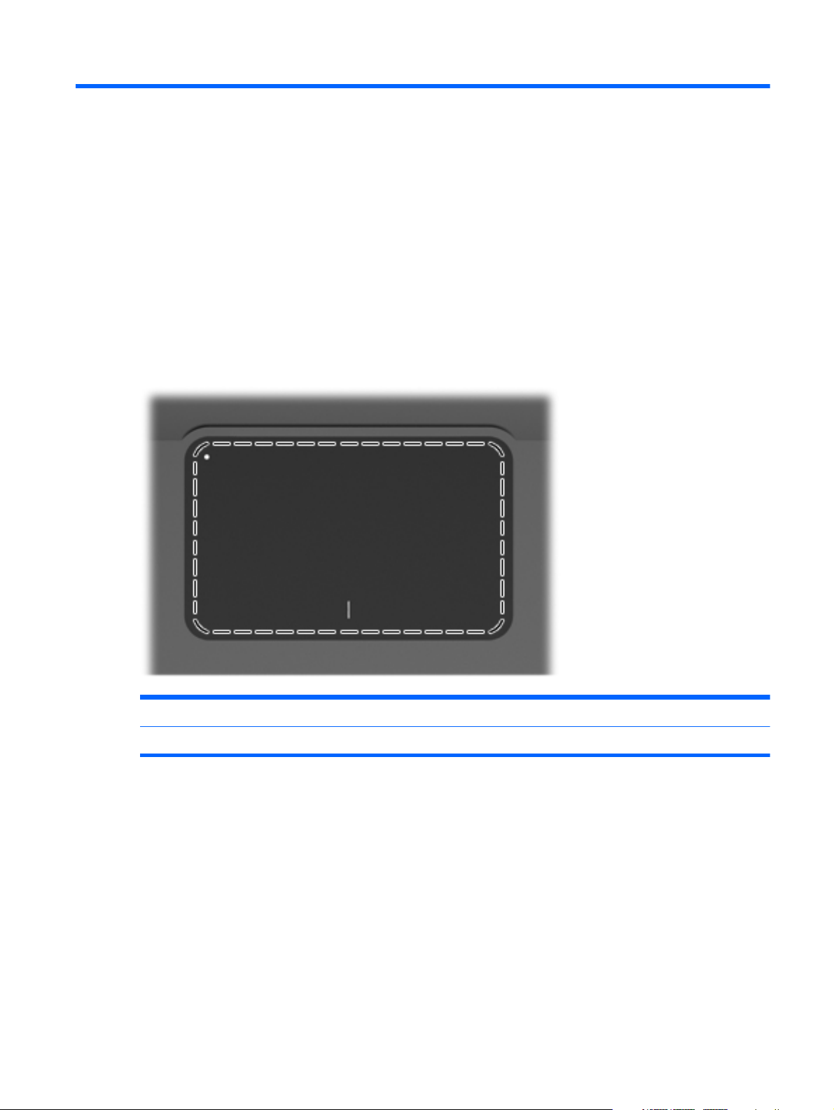
TouchPad
Component Function
TouchPad Moves the pointer and selects or activates items on the screen.
To view or change the pointing device preferences:
1. Select Start > Devices and Printers.
2. Right-click the device representing the computer.
3. Select Mouse settings.
Top components
5
Page 14
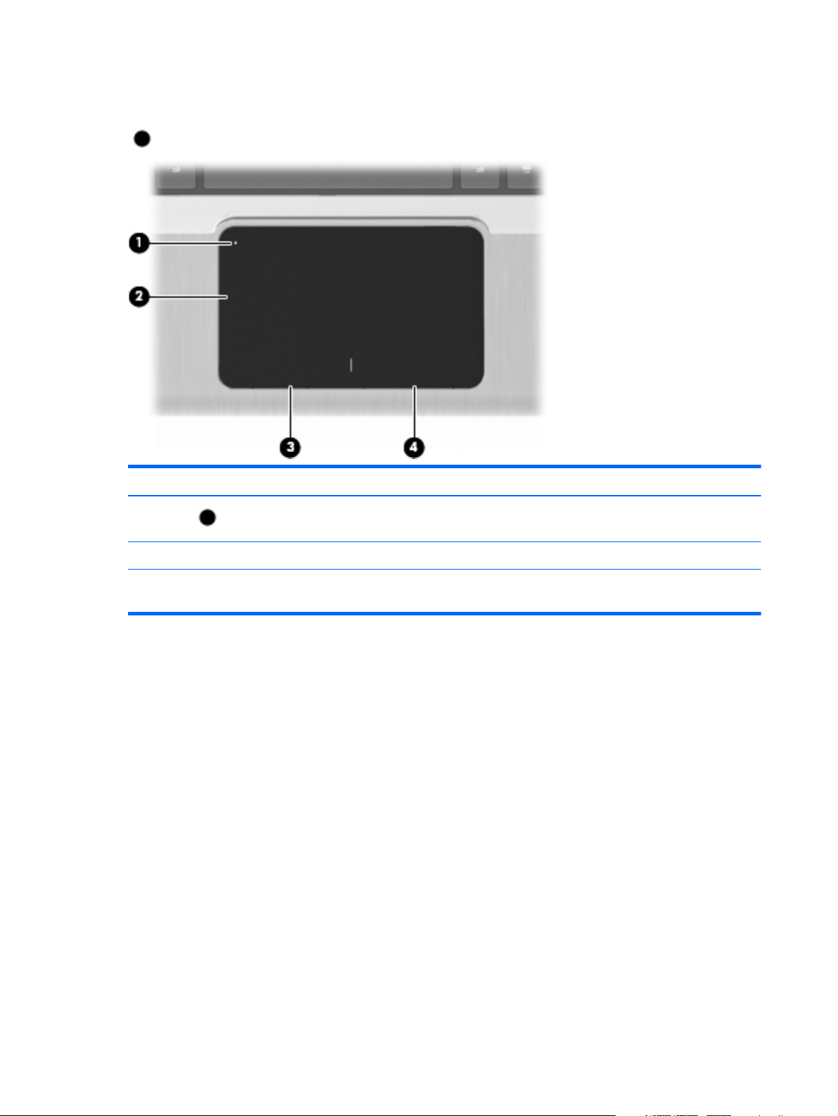
TouchPad buttons
Item Description Function
1
2 Left TouchPad button Functions like the left button on an external mouse.
3 Right TouchPad button Functions like the right button on an external
TouchPad On/Off button Turns the TouchPad on and off. Quickly double-tap
to turn the TouchPad on and off.
mouse.
To view or change pointing device preferences:
1. Select Start > Devices and Printers.
2. Right-click the device representing your computer.
3.
Select Mouse settings.
6 Chapter 2 External component identification
Page 15
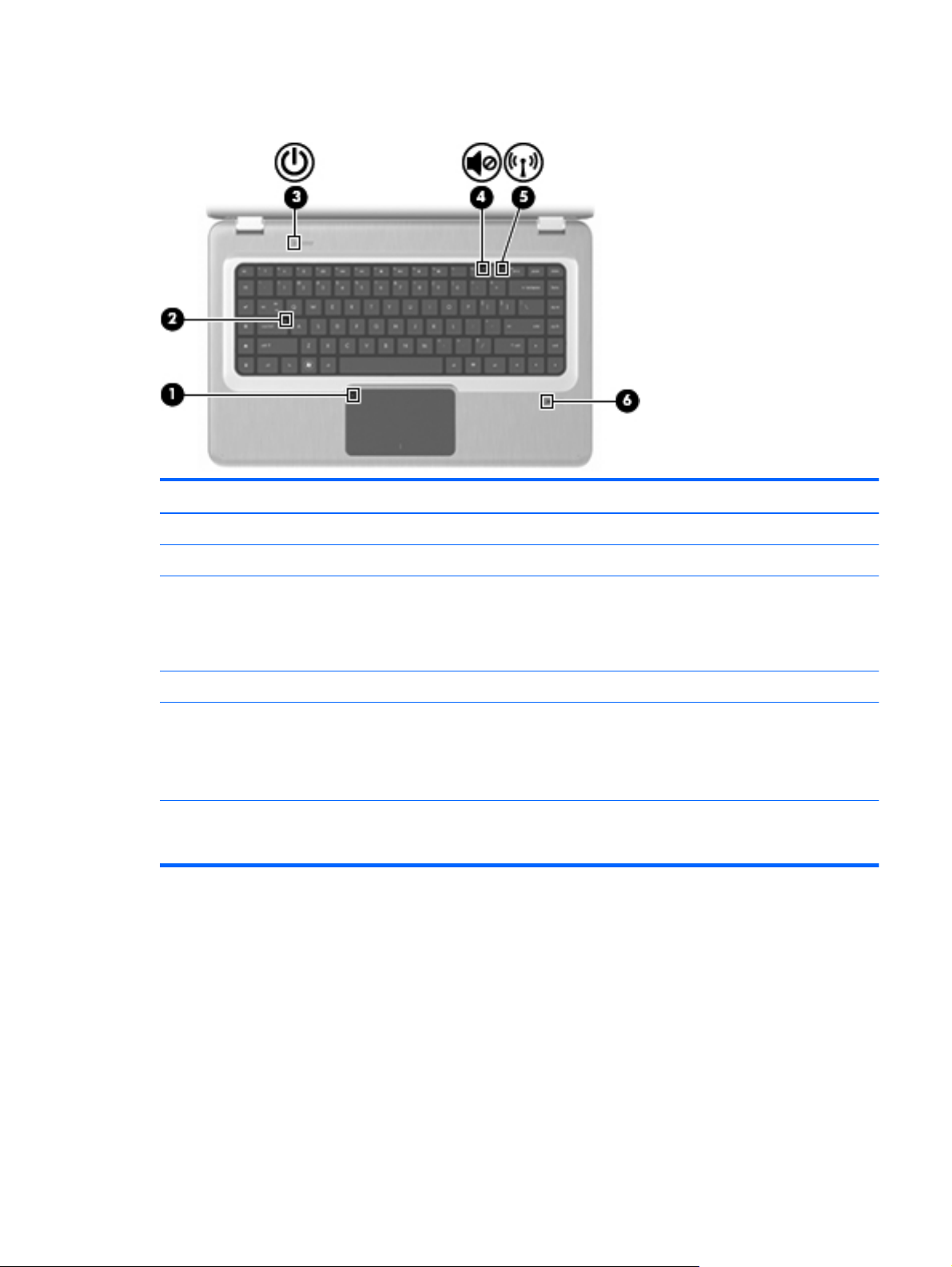
Lights
Item Description Function
1 TouchPad light Amber—The TouchPad is disabled.
2 Caps Lock light On—The Caps Lock is on.
3Power light
4 Volume Mute light Amber—The computer sound is off.
5 Wireless light
6 Fingerprint Reader light
●
On—The computer is on.
●
Flashing—The computer is in Sleep.
●
Off—The computer is off or in Hibernation.
●
White—An integrated wireless device, such as a
wireless local area network (WLAN) device and/or
a Bluetooth® device, is detected.
●
Amber—No wireless devices are detected.
●
White—The fingerprint was read.
●
Amber—The fingerprint was not read.
Top components
7
Page 16
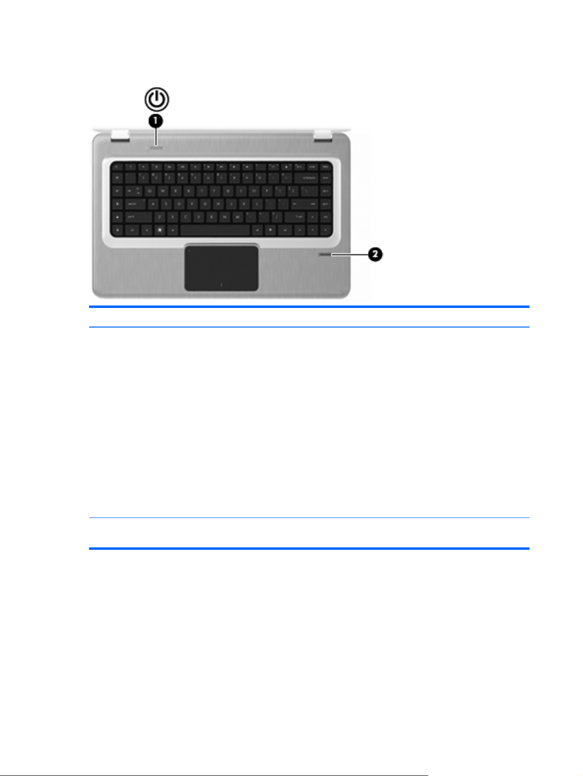
Buttons and Fingerprint Reader (select models only)
Item Description Function
1 Power button Press the Power button to:
●
Turn on the computer.
●
Initiate Sleep.
●
Exit Sleep.
●
Exit Hibernation.
If the computer has stopped responding and Windows
shutdown procedures are ineffective, press and hold the
Power button for at least five seconds to shut down the
computer.
For more information about the power settings, select
Start > Control Panel > System and Security >
Power Options.
2 Fingerprint Reader (select models only) Allows a fingerprint logon to Windows, instead of a
password logon.
For information about changing the factory settings, see Help and Support.
8 Chapter 2 External component identification
Page 17
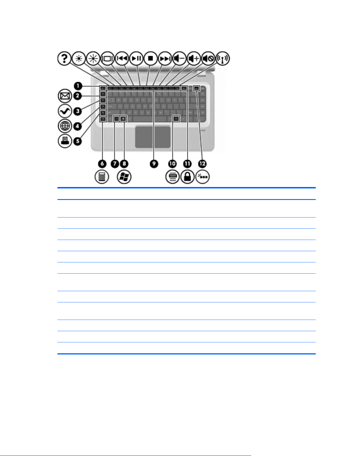
Keys
Item Description Function
1 esc key Press the esc and fn keys at the same time to display
system information.
2 E-mail key Opens a new e-mail in the default e-mail client.
3 Media Application key Launches the MediaSmart application.
4 Web Browser key Launches the default web browser.
5 Print key Sends the currently-active document to the default printer.
6 Calculator key Launches the Calculator application.
7 fn key Press the fn key at the same time as a function key or the
esc key to execute frequently used system functions.
8 Windows Logo key Displays the Windows Start menu.
9 Function keys Press a function key and the fn key at the same time to
execute frequently used system functions.
10 Windows Application key Displays a shortcut menu for items beneath the pointer.
11 QuickLock key Initiates QuickLock.
12 Backlight key Turns the backlit keyboard on or off.
Top components
9
Page 18
Front components
Description Function
Speakers Produce sound.
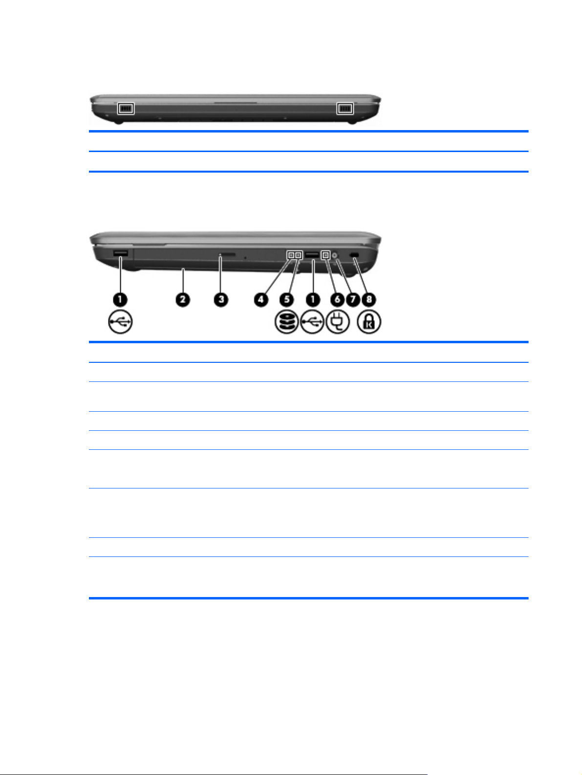
Right-side components
Item Description Function
1 USB ports (2) Connect optional USB devices.
2 Optical drive Reads optical discs and, on select models, writes to
optical discs.
3 Optical Drive light Flashing—Accessing the optical drive.
4 Hibernate light White—The computer is in Hibernate.
5 Hard Disk Drive light
6 AC Adapter light
7 Power connector Connects an AC adapter.
8 Security Cable slot Connects an optional security cable. The security cable is
●
White—The hard disk drive is active.
●
Amber—The hard disk drive is parked.
●
On—The computer is connected to external power.
●
Off—The computer is not connected to external
power.
designed to act as a deterrent, but might not prevent the
computer from being mishandled or stolen.
10 Chapter 2 External component identification
Page 19
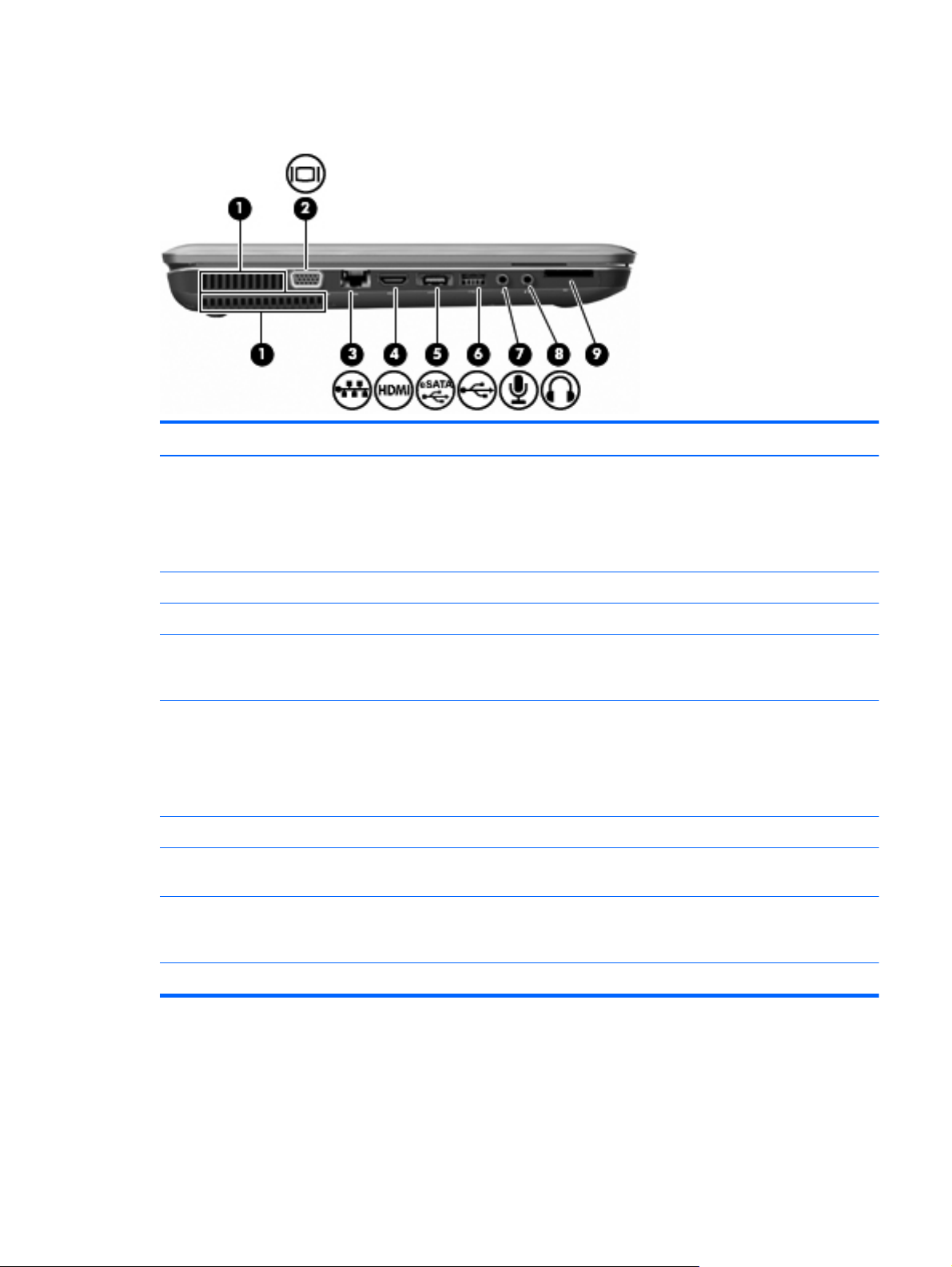
Left-side components
Item Description Function
1 Vents (2) Enable airflow to cool internal components.
NOTE: The computer fan starts up automatically to cool
internal components and prevent overheating. It is normal
for the internal fan to cycle on and off during routine
operation.
2 External Monitor port Connects an external VGA monitor or projector.
3 RJ-45 (network) jack Connects a network cable.
4 HDMI port Connects an optional video or audio device, such as a
high-definition television, or any compatible digital or
audio component.
5 eSATA/USB port (select models only) Connects an optional high-performance eSATA
component, such as an eSATA external hard drive, or
connects an optional USB device.
NOTE: Depending on the computer model, the
computer might include only a USB port.
6 USB port Connects an optional USB device.
7 Audio-in (microphone) jack Connects an optional computer headset microphone,
stereo array microphone, monaural microphone.
8 Audio-out (headphone) jack Produces sound when connected to optional powered
stereo speakers, headphones, ear buds, a headset, or
television audio.
9 SD card reader Reads SD cards that are inserted into the reader.
Left-side components
11
Page 20
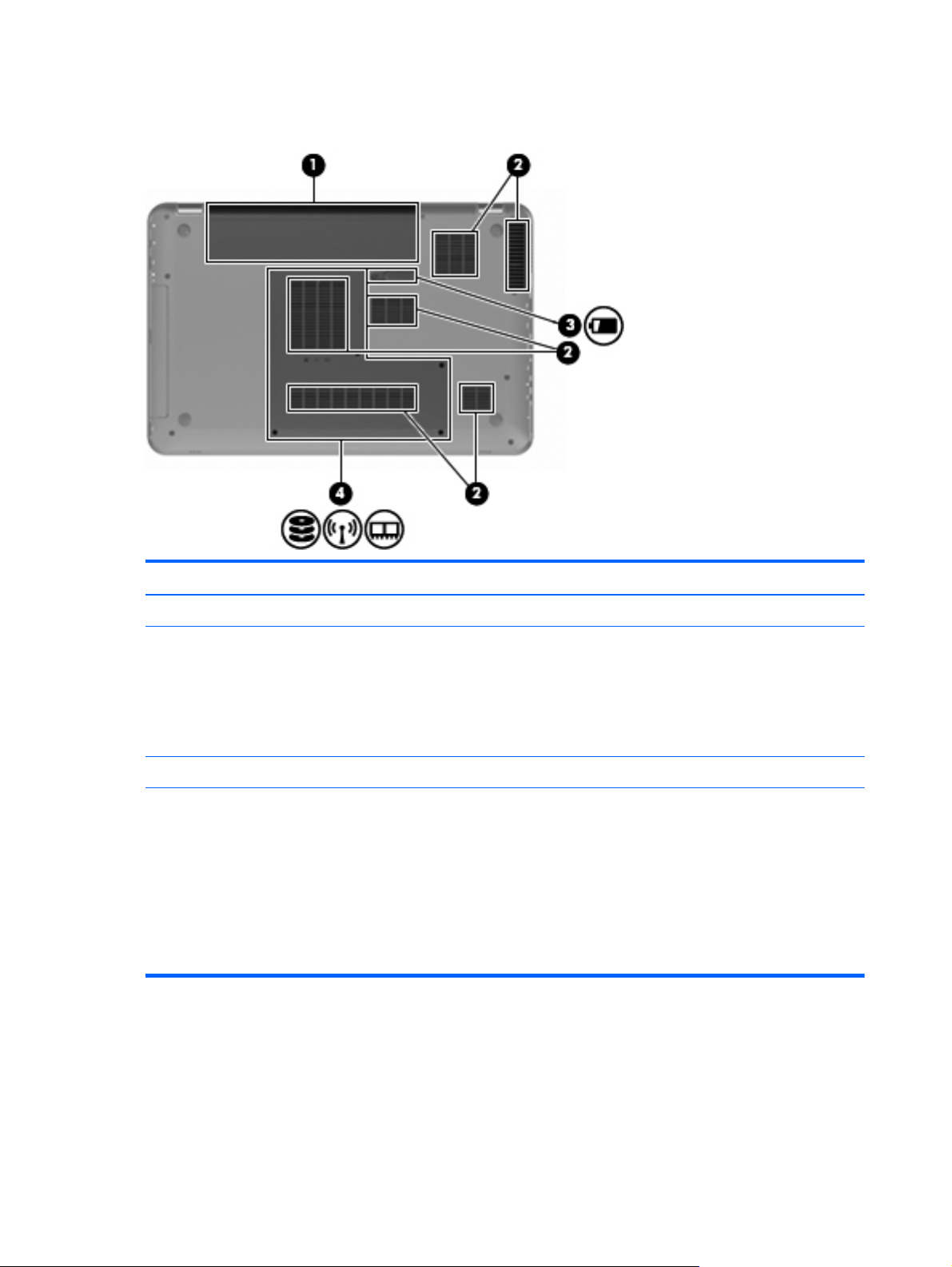
Bottom components
Item Description Function
1 Battery bay Holds the battery.
2 Vents (6) Enable airflow to cool internal components.
NOTE: The computer fan starts up automatically to cool
internal components and prevent overheating. It is normal
for the internal fan to cycle on and off during routine
operation.
3 Battery Release latch Releases the battery from the battery bay.
4 Primary Hard Drive bay Holds the primary hard drive, the memory module slots,
and the WLAN module (select models only).
CAUTION: To prevent an unresponsive system, replace
the wireless module with a wireless module authorized for
use by the governmental agency that regulates wireless
devices in your country or region. If you replace the
module and then receive a warning message, remove the
module to restore computer functionality, and then contact
technical support through Help and Support.
12 Chapter 2 External component identification
Page 21
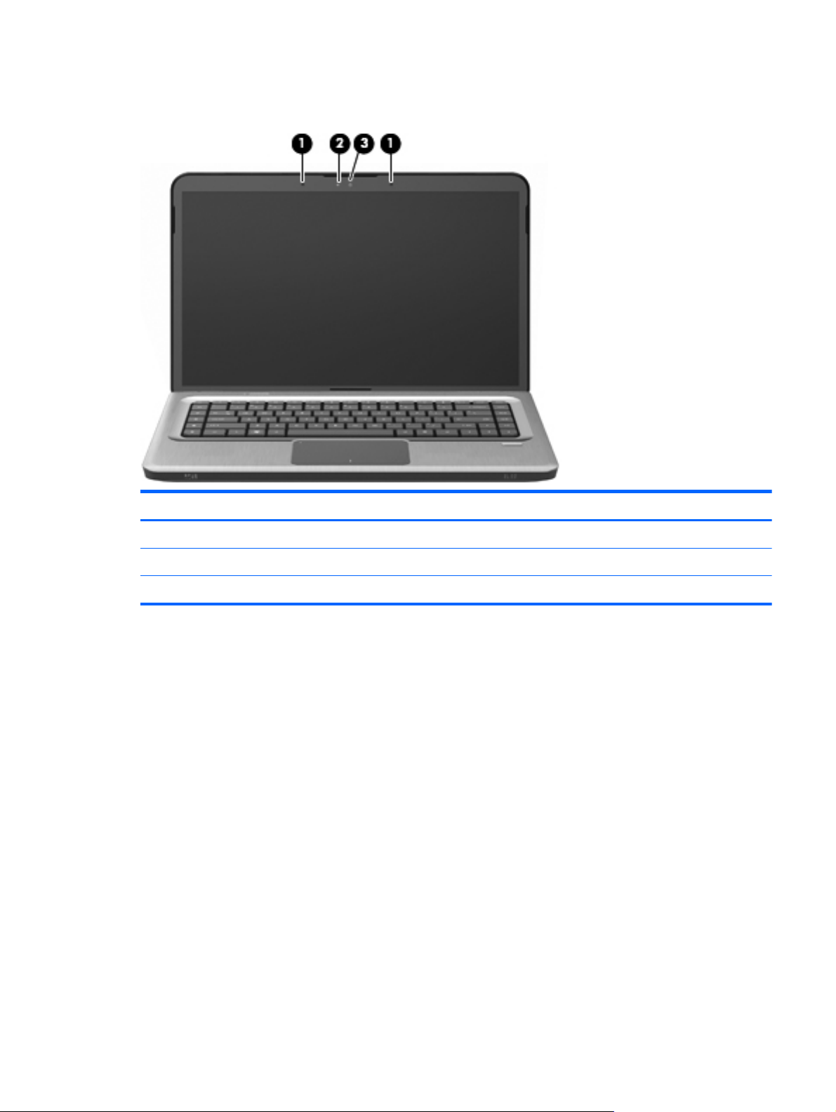
Display components
Item Description Function
1 Internal microphones (2) Record sound.
2 Webcam light On—The webcam is in use.
3 Webcam Records video and captures still photographs.
Display components
13
Page 22
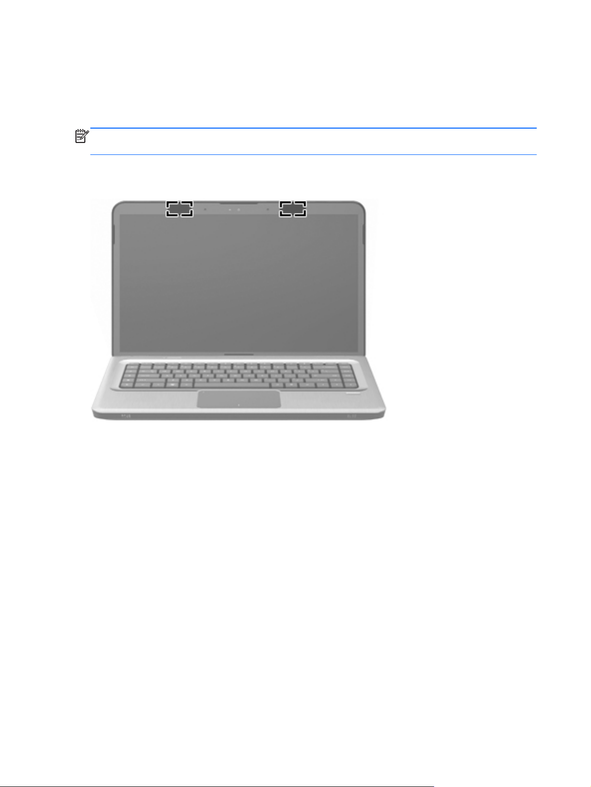
Wireless antennas
Two antennas send and receive signals from one or more wireless devices. These antennas are not
visible from the outside of the computer.
NOTE: For optimal transmission, keep the areas immediately around the antennas free from
obstructions.
To review wireless regulatory notices, see the country-specific section of the Regulatory, Safety and
Environmental Notices chapter in Help and Support.
14 Chapter 2 External component identification
Page 23
3 Illustrated parts catalog
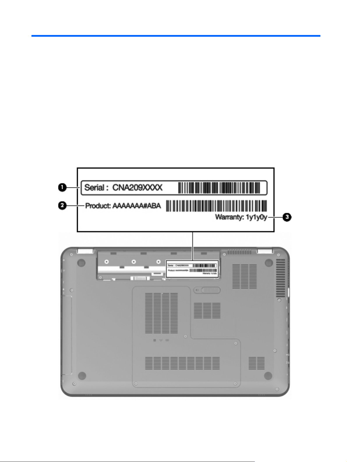
Service tag
When ordering parts or requesting information, provide the computer serial number and model
description provided on the service tag.
Service tag
15
Page 24

Item Description Function
1 Serial number (s/n) This is an alphanumeric identifier that is unique to
each product.
2 Part number/Product number (p/n) This number provides specific information about the
product's hardware components. The part number
helps a service technician to determine what
components and parts are needed.
3 Warranty period This number describes the duration of the warranty
period for the computer.
16 Chapter 3 Illustrated parts catalog
Page 25
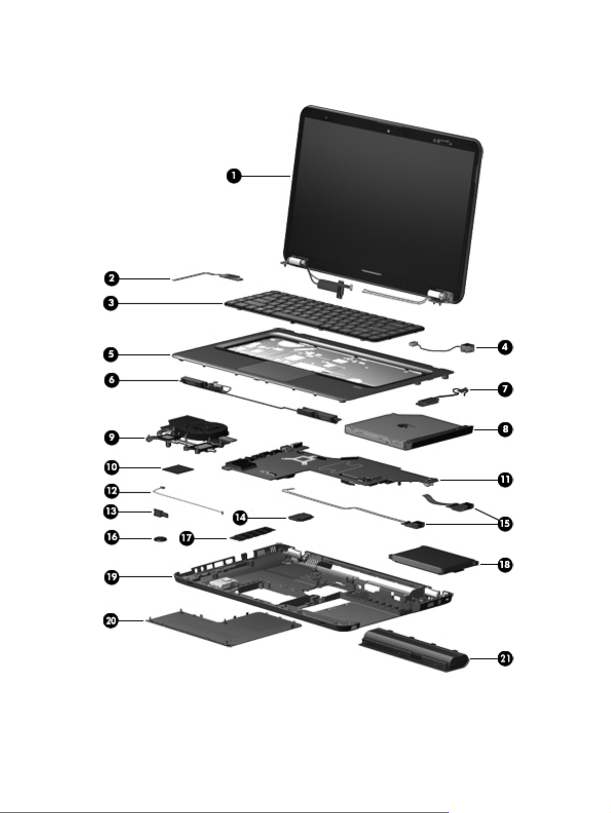
Computer major components
Computer major components
17
Page 26

Item Description Spare part number
1 Display assembly, 15.6-in, high definition (HD) with webcam and two microphones (includes
wireless antenna transceivers and cables):
TouchScreen display assembly with etched finish 631019-001
For use with computer models with black finish and WiMax 629279-001
For use with computer models with etched finish and WiMax 629280-001
For use with computer models with black finish 603647-001
For use with computer models with chrome finish 603650-001
For use with computer models with etched finish 595131-001
For use with computer models with midnight blue finish 615932-001
For use with computer models with shell white finish 603648-001
For use with computer models with Sonoma red finish 603649-001
NOTE: For more information about display assembly spare part numbers, see
on page 21.
2 Power button board (includes cable) 603682-001
3 Keyboard with backlight (dura-coat, island-style, includes keyboard cable):
For use in Brazil 597630-201
For use in Canada 597630-121
For use in Japan 597630-291
For use in Latin America 597630-161
For use in Taiwan 597630-AD1
For use in South Korea 597630-AB1
For use in Thailand 597630-281
For use in the United States 597630-001
Keyboard with backlight (dura-coat, island-style, includes keyboard cable):
For use in Brazil 597635-201
For use in Canada 597635-121
For use in Japan 597635-291
Display assembly components
For use in Latin America 597635-161
For use in Taiwan 597635-AD1
For use in South Korea 597635-AB1
For use in Thailand 597635-281
For use in the United States 597635-001
4 Power connector 603692-001
18 Chapter 3 Illustrated parts catalog
Page 27

Item Description Spare part number
5 Top cover (includes TouchPad):
For use with computer models in etched finish equipped with fingerprint reader 603684-001
For use with computer models with black finish 603685-001
For use with computer models with chrome finish 603688-001
For use with computer models with midnight blue finish 615934-001
For use with computer models with shell white finish 603686-001
For use with computer models with Sonoma red finish 603687-001
6 Speaker assembly 603694-001
7 Optical drive cable 603680-001
8 Optical drive (includes bezel and bracket)
Blu-ray ROM with LightScribe DVD±RW SuperMulti DL Drive 614332-001
Blu-ray ROM with LightScribe Combo Drive 603678-001
DVD±RW SuperMulti Double-Layer Drive with LightScribe 603677-001
9 Fan/heat sink assembly (includes replacement thermal material):
For use with computer models equipped with a graphics subsystem with discrete
memory
For use with computer models equipped with a graphics subsystem with UMA memory 634455-001
10 Processor (includes replacement thermal material):
Intel Core i7-2820QM 2.30-GHz (turbo up to 3.40-GHz) processor, 8-MB L2 cache,
1600 MHz, 45 W
Intel Core i7-2720QM 2.20-GHz (turbo up to 3.30-GHz) processor, 6-MB L2 cache,
1600 MHz, 45 W
Intel Core I7-2630QM 2.00-GHz (turbo up to 2.90-GHz) processor, 6-MB L2 cache,
1600 MHz, 45 W
11 System board (includes replacement thermal material):
For use with computer models equipped with a graphics subsystem with discrete
memory
For use with computer models equipped with a graphics subsystem with UMA memory 633555-001
12 Bluetooth module cable 603645-001
13 Bluetooth module 537921-001
14 WLAN module:
Intel Centrino Advanced-N + WiMax 6250 WLAN module for use in the United States 619997-001
634454-001
634694-001
631254-001
635501-001
633554-001
Intel Centrino Wireless-N 1000 802.11b/g/n 1×2 WLAN module 593530-001
Ralink 5390GN 802.11b/g/n 1×1 WiFi Adapter 630703-001
Computer major components
19
Page 28

Item Description Spare part number
Ralink 8190BC8 802.11b/g/n 1×1 WiFi and Bluetooth 3.0+HS Combo Adapter 630813-001
Ralink RT3090BC4 802.11b/g/n 1×1 WiFi and Bluetooth 2.1+EDR Combo Adapter
(BT3.0+HS ready)
15 USB board (includes cable) 603683-001
16 RTC battery 599516-001
17 Memory module (PC3-10600, SO-DIMM)
4 GB 599092-001
2 GB 598956-001
1 GB 598859-001
18 Hard drive kit (includes left and right bracket rails, connector cable, Mylar cover with tab, 4 screws and 4 rubber
isolators):
750-GB, 5200-rpm 633252-001
500-GB, 7200-rpm 603669-001
250-GB, 7200-rpm 603667-001
Hard drive only (does not include bracket rails, connector cable, Mylar cover with tab, screws, or isolators):
1-TB, 5200-rpm 603788-001
640-GB, 7200-rpm 621046-001
630705-001
320-GB, 7200-rpm 603783-001
160-GB solid state drive (SSD, includes left and right bracket rails, connector
cable, Mylar cover with tab, 4 screws and 4 rubber isolators)
Hard Drive Hardware Kit (not illustrated, includes left and right bracket rails,
connector cable, Mylar cover with tab, and four rubber isolators)
19 Base enclosure (includes four rubber feet) 640296-001
Rubber feet (not illustrated, includes 4 base enclosure rubber feet) 603696-001
20 Plastics Kit (includes hard drive bay cover)
NOTE: For more information, see
21 Battery
9-cell, 93-Whr, 2.80-Ah Li-ion battery for use with all computer models 593550-001
6-cell, 62-Whr, 2.80-Ah Li-ion battery for use with all computer models 593562-001
6-cell, 55-Whr, 2.55-Ah Li-ion battery for use with all computer models 593554-001
Plastics Kit on page 26.
603673-001
603676-001
603679-001
20 Chapter 3 Illustrated parts catalog
Page 29
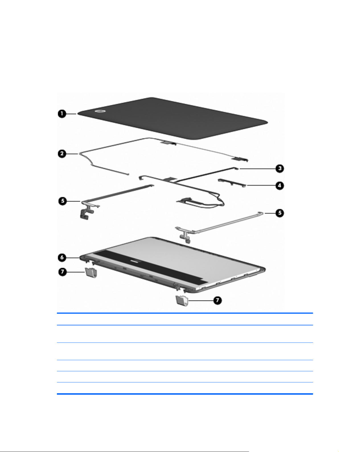
Display assembly components
The HP Pavilion dv6 Entertainment PC offers two types of display assemblies. Component spare parts
are listed in this section for TouchScreen and BrightView display assemblies.
TouchScreen display assembly spare parts
Item Description Spare part number
1 Display enclosure with etched finish (includes wireless antenna transceivers and
cables and logo LED board and cable)
2 Wireless antenna transceivers and cables Included with the display
3 Display Cable Kit 603665-001
4 Webcam/microphone module (includes cable) 603660-001
5 Display Hinge Kit (includes left and right hinges) 603664-001
603663-001
enclosure
Display assembly components
21
Page 30

Item Description Spare part number
6 TouchScreen display panel Included with the display
assembly
7 Display hinge cover (includes left and right covers) 603666-001
Display Rubber Kit (not illustrated, includes display bezel rubber screw covers) 603659-001
Display Screw Kit (not illustrated) 603658-001
22 Chapter 3 Illustrated parts catalog
Page 31

BrightView display assembly spare parts
Item Description Spare part number
1 Display bezel 603651-001
2 BrightView display panel 595130-001
3 Display Hinge Kit (includes left and right hinges) 603656-001
4 Webcam/microphone module (includes cable) 603660-001
5 Display Cable Kit 603657-001
Display Cable Kit for use only with computer models equipped with WiMax 629284-001
6 Display hinge cover 603661-001
7 Display enclosure (includes wireless antenna transceivers and cables and logo LED board and cable)
With black finish for use with computer models equipped with WiMax 629282-001
With etched finish for use with computer models equipped with WiMax 629283-001
Display assembly components
23
Page 32

Item Description Spare part number
With black finish 603652-001
With chrome finish 603655-001
With etched finish 604804-001
With midnight blue finish 615933-001
With shell white finish 603653-001
With Sonoma red finish 603654-001
8 Wireless antenna transceivers and cables Included with the display
enclosure
Display Rubber Kit (includes display bezel rubber screw covers) 603659-001
Display Screw Kit 603658-001
24 Chapter 3 Illustrated parts catalog
Page 33

Mass storage devices
Item Description Spare part number
1 Hard drive kit (includes left and right bracket rails, connector cable, Mylar cover with tab, 4 screws and 4
rubber isolators):
750-GB, 5200-rpm 633252-001
500-GB, 7200-rpm 603669-001
250-GB, 7200-rpm 603667-001
Hard drive only (does not include bracket rails, connector cable, Mylar cover with tab, screws, or isolators):
1-TB, 5200-rpm 603788-001
640-GB, 7200-rpm 621046-001
320-GB, 7200-rpm 603783-001
160-GB solid state drive (SSD, includes left and right bracket rails, connector
cable, Mylar cover with tab, 4 screws and 4 rubber isolators)
Hard Drive Hardware Kit (not illustrated, includes left and right bracket rails,
connector cable, Mylar cover with tab, and four rubber isolators)
2 Optical drive (includes bezel and bracket)
Blu-ray ROM with LightScribe DVD±RW SuperMulti DL Drive 614332-001
Blu-ray ROM with LightScribe Combo Drive 603678-001
DVD±RW SuperMulti Double-Layer Drive with LightScribe 603677-001
603673-001
603676-001
Mass storage devices
25
Page 34

Plastics Kit
Item Description Spare part number
1 Hard drive bay cover (includes four captive screws) 603679-001
26 Chapter 3 Illustrated parts catalog
Page 35

Miscellaneous parts
Description Spare part number
AC adapter:
120W HP Smart AC adapter PFC RC V 3W 609941-001
90W HP Smart AC adapter PFC RC V 3W 609940-001
90W HP Smart AC adapter PFC RC V EM 3W 609947-001
Cable housing 603697-001
Power cord (1.83-m (6-foot), 3-wire):
For use in Argentina 490371-D01
For use in Australia 490371-011
For use in Brazil 490371-202
For use in Europe 490371-021
For use in India 490371-D61
For use in Italy 490371-061
For use in Japan 490371-291
For use in Canada, Mexico, and North America 490371-001
For use in the People's Republic of China 490371-AA1
For use in South Korea 490371-AD1
For use in Taiwan 490371-AB1
For use in Thailand 490371-281
For use in Singapore and the United Kingdom 490371-031
Remote control (full-function with teletext, select models only) 465541-004
Screw Kit 603681-001
USB DVB-T TV dipole antenna 581222-001
USB DVB-T TV tuner antenna (select models only) 581223-001
Sequential part number listing
Spare part
number
465541-004 Remote control (full-function with teletext, select models only)
Description
490371-001 Power cord for use in Canada, French Canada, Latin America, and the United States
490371-011 Power cord for use in Australia and New Zealand
Miscellaneous parts
27
Page 36

Spare part
number
490371-021 Power cord for use in Belgium, Europe, Finland, France, Germany, Greece, the Netherlands, Norway,
490371-031 Power cord for use in the United Kingdom and Hong Kong
490371-061 Power cord for use in Italy
490371-201 Power cord for use in Thailand
490371-202 Power cord for use in Brazil
490371-291 Power cord for use in Japan
490371-AA1 Power cord for use in the People's Republic of China
490371-AB1 Power cord for use in Taiwan
490371-AD1 Power cord for use in South Korea
490371-D01 Power cord for use in Argentina
490371-D61 Power cord for use in India
537921-001 Bluetooth module (does not include Bluetooth module cable)
581222-001 DVB-T TV tuner (select models only)
Description
Portugal, Spain, and Sweden
581223-001 DVB-T TV tuner antenna (select models only)
593530-001 Intel Centrino Wireless-N 1000 802.11b/g/n 1×2 WLAN module
593550-001 9-cell, 93-Whr, 2.8-Ah Li-ion battery
593554-001 6-cell, 55-Whr, 2.55-Ah Li-ion battery
593562-001 6-cell, 62-Whr, 2.8-Ah Li-ion battery
595130-001 Display panel for use with computer models equipped with BrightView panel (includes display panel
cable)
595131-001 Display assembly with etched finish, 15.6-in, BrightView, HD, LED, equipped with webcam module, and
2 microphones (includes display panel cable, WLAN antenna transceivers and cables)
597630-001 Backlit keyboard for use in the United States
597630-121 Backlit keyboard for use in French Canada
597630-161 Backlit keyboard for use in Latin America
597630-201 Backlit keyboard for use in Brazil
597630-281 Backlit keyboard for use in Thailand
597630-291 Backlit keyboard for use in Japan
597630-AB1 Backlit keyboard for use in Taiwan
597630-AD1 Backlit keyboard for use in South Korea
597635-001 Keyboard for use in the United States
597635-121 Keyboard for use in French Canada
28 Chapter 3 Illustrated parts catalog
Page 37

Spare part
number
597635-161 Keyboard for use in Latin America
597635-201 Keyboard for use in Brazil
597635-281 Keyboard for use in Thailand
597635-291 Keyboard for use in Japan
597635-AB1 Keyboard for use in Taiwan
597635-AD1 Keyboard for use in Korea
598856-001 2-GB memory module
598859-001 1-GB memory module
599092-001 4-GB memory module
599516-001 RTC battery
603645-001 Bluetooth module cable and rubber kit
603647-001 39.6-cm (15.6-inch) HD BrightView display assembly with low light VGA webcam and two microphones,
603648-001 39.6-cm (15.6-inch) HD BrightView display assembly with low light VGA webcam and two microphones,
Description
Black (includes wireless antenna transceivers and cables)
White (includes wireless antenna transceivers and cables)
603649-001 39.6-cm (15.6-inch) HD BrightView display assembly with low light VGA webcam and two microphones,
Red (includes wireless antenna transceivers and cables)
603650-001 39.6-cm (15.6-inch) HD BrightView display assembly with low light VGA webcam and two microphones,
Chrome (includes wireless antenna transceivers and cables)
603651-001 BrightView display bezel
603652-001 Black display enclosure (includes wireless antenna transceivers and cables and LED board and cable)
603653-001 White display enclosure (includes wireless antenna transceivers and cables and LED board and cable)
603654-001 Red display enclosure (includes wireless antenna transceivers and cables and LED board and cable)
603655-001 Chrome display enclosure (includes wireless antenna transceivers and cables and LED board and cable)
603656-001 BrightView Display Hinge Kit (includes left and right hinges)
603657-001 BrightView Display Cable Kit (includes display panel cable)
603658-001 Display Screw Kit
603659-001 Display Rubber Kit (includes display bezel rubber screw covers)
603660-001 Webcam/microphone module (includes cable)
603661-001 BrightView display hinge covers
603663-001 TouchScreen display enclosure (includes wireless antenna transceivers and cables LED board and cable)
603664-001 TouchScreen Display Hinge Kit
603665-001 TouchScreen Display Cable Kit
Sequential part number listing
29
Page 38

Spare part
number
603666-001 TouchScreen display hinge covers
603667-001 250-GB, 7200 RPM hard drive (includes left and right bracket rails, connector cable, Mylar cover with
603669-001 500-GB, 5400 RPM or 500-GB, 7200 RPM hard drive (includes left and right bracket rails, connector
603673-001 160-GB solid state drive (SSD) (includes left and right bracket rails, connector cable, Mylar cover with
603676-001 Hard Drive Hardware Kit (includes left and right bracket rails, connector cable, Mylar cover with tab, 4
603677-001 DVD±RW SuperMulti Double-Layer Drive with LightScribe
603678-001 Blu-ray ROM with LightScribe Combo Drive
603679-001 Plastics Kit
603680-001 Optical drive cable
603681-001 Screw Kit
603682-001 Power button board (includes cable)
603683-001 USB board (includes cable)
Description
tab, and four rubber isolators)
cable, Mylar cover with tab, and four rubber isolators)
tab, and four rubber isolators)
screws, and four rubber isolators)
603684-001 Top cover with etched finish for use only with computer models equipped with a fingerprint reader
603685-001 Top cover with black finish for use only with computer models not equipped with a fingerprint reader
603686-001 Top cover with shell white finish for use only with computer models not equipped with a fingerprint
reader
603687-001 Top cover with Sonoma red finish for use only with computer models not equipped with a fingerprint
reader
603688-001 Top cover with chrome finish for use only with computer models not equipped with a fingerprint reader
603692-001 Power connector and cable
603694-001 Speaker assembly
603696-001 Rubber feet
603697-001 Cable housing
603783-001 320-GB, 7200 RPM hard drive only (does not include bracket rails, connector cable, Mylar cover with
tab, screws, or and rubber isolators)
603788-001 1-TB, 5200 RPM hard drive only (does not include bracket rails, connector cable, Mylar cover with tab,
screws, or and rubber isolators)
604804-001 Display enclosure with etched finish (includes wireless antenna transceivers and LED board and cable)
609940-001 90-W HP Smart AC adapter PFC RC V 3W
609941-001 120-W HP Smart AC adapter PFC RC V 3W
609947-001 90-W HP Smart AC adapter PFC RC V EM 3W
30 Chapter 3 Illustrated parts catalog
Page 39

Spare part
number
614332-001 Blu-ray ROM with LightScribe DVD±RW SuperMulti DL Drive
615932-001 Display assembly 15.6-in HD BrightView in midnight blue finish with webcam and two microphones
615933-001 Display enclosure in midnight blue finish (includes wireless antenna transceivers and cables and LED
615934-001 Top cover with midnight blue finish for use only with computer models not equipped with a fingerprint
619997-001 Intel Centrino Advanced-N + WiMax 6250 WLAN module for use in the United States
621046-001 640-GB, 7200 RPM hard drive only (does not include bracket rails, connector cable, Mylar cover with
629279-001 Display assembly with chrome finish, 15.6-in, BrightView, HD, LED, equipped with webcam module, 2
629280-001 Display assembly with etched finish, 15.6-in, BrightView, HD, LED, equipped with webcam module, 2
629282-001 Display enclosure with black finish (includes wireless antenna transceivers and cables and LED board
Description
board and cable)
reader
tab, screws, or rubber isolators)
microphones, and WiMax (includes display panel cable, WLAN, and WWAN antenna transceivers and
cables)
microphones, and WiMax (includes display panel cable, WLAN, and WWAN antenna transceivers and
cables)
and cable) with WiMax
629283-001 Display enclosure with etched finish (includes wireless antenna transceivers and cables and LED board
and cable) with WiMax
629284-001 Display Cable Kit for use only on computer models equipped with a BrightView display assembly with
WiMax (includes display panel cable)
630703-001 Ralink 5390GN 802.11b/g/n 1×1 WiFi Adapter
630705-001 Ralink RT3090BC4 802.11b/g/n 1×1 WiFi and Bluetooth 2.1+EDR Combo Adapter (BT3.0+HS ready)
630813-001 Ralink 8190BC8 802.11b/g/n 1×1 WiFi and Bluetooth 3.0+HS Combo Adapter
631019-001 TouchScreen display assembly, 15.6-in, LED, HD, BrightView, equipped with webcam module and
microphone (includes display panel cable and WLAN antenna transceivers and cables)
631254-001 Intel Core i7-2720QM 2.20-GHz (turbo up to 3.30-GHz) processor, 6-MB L2 cache, 1600 MHz, 45 W
633252-001 750-GB, 7200 RPM hard drive (includes left and right bracket rails, connector cable, Mylar cover with
tab, 4 screws, or 4 rubber isolators)
633554-001 System board (Intel HM65 Express chipset) for use only with computer models equipped with a graphics
subsystem with discrete memory (includes 1-GB of graphics subsystem memory)
633555-001 System board (HM65 chipset) for use only with computer models equipped with a graphics subsystem
with UMA memory
634454-001 Thermal module for use only with computer models equipped with a graphics subsystem with discrete
memory
634455-001 Thermal module for use only with computer models equipped with a graphics subsystem with UMA
memory
634694-001 Intel Core i7-2820QM 2.30-GHz (turbo up to 3.40-GHz) processor, 8-MB L2 cache, 1600 MHz, 45 W
Sequential part number listing
31
Page 40

Spare part
number
635501-001 Intel Core I7-2630QM 2.00-GHz (turbo up to 2.90-GHz) processor, 6-MB L2 cache, 1600 MHz, 45 W
640296-001 Base enclosure (includes rubber feet and battery release latch)
Description
32 Chapter 3 Illustrated parts catalog
Page 41

4 Removal and replacement
procedures
Preliminary replacement requirements
Tools required
Use the following tools to complete the removal and replacement procedures:
●
Non-magnetic screwdriver
●
Phillips P0 and P1 screwdrivers
●
Flat-bladed screwdriver
Service considerations
The following sections include some of the considerations that you must keep in mind during
disassembly and assembly procedures.
NOTE: As you remove each subassembly from the computer, place the subassembly (and all
accompanying screws) away from the work area to prevent damage.
Plastic parts
CAUTION: Using excessive force during disassembly and reassembly can damage plastic parts. Use
care when handling the plastic parts. Apply pressure only at the points designated in the maintenance
instructions.
Preliminary replacement requirements
33
Page 42

Cables and connectors
CAUTION: When servicing the computer, be sure that cables are placed in their proper locations
during the reassembly process. Improper cable placement can damage the computer.
Cables must be handled with extreme care to avoid damage. Apply only the tension required to unseat
or seat the cables during removal and insertion. Handle cables by the connector whenever possible. In
all cases, avoid bending, twisting, or tearing cables. Be sure that cables are routed in such a way that
they cannot be caught or snagged by parts being removed or replaced. Handle flex cables with
extreme care; these cables tear easily.
Drive handling
CAUTION: Drives are fragile components that must be handled with care. To prevent damage to the
computer, damage to a drive, or loss of information, observe these precautions:
Before removing or inserting a hard drive, shut down the computer. If you are unsure whether the
computer is off or in Hibernation, turn the computer on, and then shut it down through the operating
system.
Before handling a drive, be sure that you are discharged of static electricity. While handling a drive,
avoid touching the connector.
Before removing a diskette drive or optical drive, be sure that a diskette or disc is not in the drive and
be sure that the optical drive tray is closed.
Handle drives on surfaces covered with at least one inch of shock-proof foam.
Avoid dropping drives from any height onto any surface.
After removing a hard drive, an optical drive, or a diskette drive, place it in a static-proof bag.
Avoid exposing a hard drive to products that have magnetic fields, such as monitors or speakers.
Avoid exposing a drive to temperature extremes or liquids.
If a drive must be mailed, place the drive in a bubble pack mailer or other suitable form of protective
packaging and label the package “FRAGILE.”
34 Chapter 4 Removal and replacement procedures
Page 43

Grounding guidelines
Electrostatic discharge damage
Electronic components are sensitive to electrostatic discharge (ESD). Circuitry design and structure
determine the degree of sensitivity. Networks built into many integrated circuits provide some
protection, but in many cases, ESD contains enough power to alter device parameters or melt
silicon junctions.
A discharge of static electricity from a finger or other conductor can destroy static-sensitive devices or
microcircuitry. Even if the spark is neither felt nor heard, damage might have occurred.
An electronic device exposed to ESD might not be affected at all and can work perfectly throughout a
normal cycle. Or the device might function normally for a while, then degrade in the internal layers,
reducing its life expectancy.
CAUTION: To prevent damage to the computer when you are removing or installing internal
components, observe these precautions:
Keep components in their electrostatic-safe containers until you are ready to install them.
Use nonmagnetic tools.
Before touching an electronic component, discharge static electricity by using the guidelines described
in this section.
Avoid touching pins, leads, and circuitry. Handle electronic components as little as possible.
If you remove a component, place it in an electrostatic-safe container.
The following table shows how humidity affects the electrostatic voltage levels generated by different
activities.
CAUTION: A product can be degraded by as little as 700 V.
Typical electrostatic voltage levels
Relative humidity
Event 10% 40% 55%
Walking across carpet 35,000 V 15,000 V 7,500 V
Walking across vinyl floor 12,000 V 5,000 V 3,000 V
Motions of bench worker 6,000 V 800 V 400 V
Removing DIPS from plastic tube 2,000 V 700 V 400 V
Removing DIPS from vinyl tray 11,500 V 4,000 V 2,000 V
Removing DIPS from Styrofoam 14,500 V 5,000 V 3,500 V
Removing bubble pack from PCB 26,500 V 20,000 V 7,000 V
Packing PCBs in foam-lined box 21,000 V 11,000 V 5,000 V
Preliminary replacement requirements
35
Page 44

Packaging and transporting guidelines
Follow these grounding guidelines when packaging and transporting equipment:
●
To avoid hand contact, transport products in static-safe tubes, bags, or boxes.
●
Protect ESD-sensitive parts and assemblies with conductive or approved containers or packaging.
●
Keep ESD-sensitive parts in their containers until the parts arrive at static-free workstations.
●
Place items on a grounded surface before removing items from their containers.
●
Always be properly grounded when touching a component or assembly.
●
Store reusable ESD-sensitive parts from assemblies in protective packaging or nonconductive
foam.
●
Use transporters and conveyors made of antistatic belts and roller bushings. Be sure that
mechanized equipment used for moving materials is wired to ground and that proper materials
are selected to avoid static charging. When grounding is not possible, use an ionizer to dissipate
electric charges.
Workstation guidelines
Follow these grounding workstation guidelines:
●
Cover the workstation with approved static-shielding material.
●
Use a wrist strap connected to a properly grounded work surface and use properly grounded tools
and equipment.
●
Use conductive field service tools, such as cutters, screwdrivers, and vacuums.
●
When fixtures must directly contact dissipative surfaces, use fixtures made only of static-safe
materials.
●
Keep the work area free of nonconductive materials, such as ordinary plastic assembly aids and
Styrofoam.
●
Handle ESD-sensitive components, parts, and assemblies by the case or PCM laminate. Handle
these items only at static-free workstations.
●
Avoid contact with pins, leads, or circuitry.
●
Shut down power and input signals before inserting or removing connectors or test equipment.
36 Chapter 4 Removal and replacement procedures
Page 45

Equipment guidelines
Grounding equipment must include either a wrist strap or a foot strap at a grounded workstation.
●
When seated, wear a wrist strap connected to a grounded system. Wrist straps are flexible straps
with a minimum of one megohm ±10% resistance in the ground cords. To provide proper ground,
wear a strap snugly against the skin at all times. On grounded mats with banana-plug connectors,
use alligator clips to connect a wrist strap.
●
When standing, use foot straps and a grounded floor mat. Foot straps (heel, toe, or boot straps)
can be used at standing workstations and are compatible with most types of shoes or boots. On
conductive floors or dissipative floor mats, use foot straps on both feet with a minimum of one
megohm resistance between the operator and ground. To be effective, the conductive strips must
be worn in contact with the skin.
The following grounding equipment is recommended to prevent electrostatic damage:
●
Antistatic tape
●
Antistatic smocks, aprons, and sleeve protectors
●
Conductive bins and other assembly or soldering aids
●
Nonconductive foam
●
Conductive tabletop workstations with ground cords of one megohm resistance
●
Static-dissipative tables or floor mats with hard ties to the ground
●
Field service kits
●
Static awareness labels
●
Material-handling packages
●
Nonconductive plastic bags, tubes, or boxes
●
Metal tote boxes
●
Electrostatic voltage levels and protective materials
The following table lists the shielding protection provided by antistatic bags and floor mats.
Material Use Voltage protection level
Antistatic plastic Bags 1,500 V
Carbon-loaded plastic Floor mats 7,500 V
Metallized laminate Floor mats 5,000 V
Preliminary replacement requirements
37
Page 46

Component replacement procedures
This chapter provides removal and replacement procedures.
There are as many as 90 screws, in ten different sizes, that must be removed, replaced, or loosened
when servicing the computer. Make special note of each screw size and location during removal and
replacement.
Service tag
When ordering parts or requesting information, provide the computer serial number and model
description provided on the service tag.
Item Description Function
1 Serial number (s/n) An alphanumeric identifier that is unique to each product.
38 Chapter 4 Removal and replacement procedures
Page 47

Item Description Function
2 Part number/Product
3 Warranty period Describes the duration of the warranty period for the computer.
Computer feet
The computer feet are adhesive-backed rubber pads (spare part number 603696-001). There are four
rubber feet that attach to the base enclosure.
number (p/n)
Provides specific information about the product's hardware components. The part
number helps a service technician to determine what components and parts are
needed.
Component replacement procedures
39
Page 48

Battery
Description Spare part number
9-cell, 93-Wh, 2.80-Ah Li-ion battery 593550–001
6-cell, 62-Wh, 2.80-Ah Li-ion battery 593652–001
6-cell, 55-Wh, 2.55-Ah Li-ion battery 593554–001
Before disassembling the computer:
1. Shut down the computer. If you are unsure whether the computer is off or in Hibernation, turn the
computer on, and then shut it down through the operating system.
2. Disconnect all external devices connected to the computer.
3. Disconnect the power from the computer by first disconnecting the power cord from the AC outlet
and then disconnecting the AC adapter from the computer.
To remove the battery:
1. Turn the computer upside down on a flat surface.
2. Slide the battery release latch (1) to release the battery.
3. Pivot the battery (2) upward and remove it from the computer (3).
To insert the battery, insert the rear edge of the battery into the battery bay and pivot the front edge of
the battery downward until it is seated. The battery release latch automatically locks the battery into
place.
40 Chapter 4 Removal and replacement procedures
Page 49

Hard drive cover
Description Spare part number
Hard drive cover (included in the Plastics Kit) 603679-001
Before removing the hard drive cover:
1. Shut down the computer. If you are unsure whether the computer is off or in Hibernation, turn the
computer on, and then shut it down through the operating system.
2. Disconnect all external devices connected to the computer.
3. Disconnect the power from the computer by first disconnecting the power cord from the AC outlet
and then disconnecting the AC adapter from the computer.
4. Remove the
Battery on page 40.
To remove the hard drive cover:
1. Loosen the four captive screws (1) that secure the hard drive cover to the computer.
2. Lift the hard drive cover (2) away from the computer.
Reverse this procedure to install the hard drive cover.
Component replacement procedures
41
Page 50

Hard drive
Description Spare part number
Hard drive kit (includes left and right bracket rails, connector cable, Mylar cover with tab, 4 screws and 4 rubber isolators):
750-GB, 5200-rpm 633252-001
500-GB, 7200-rpm 603669-001
250-GB, 7200-rpm 603667-001
Hard drive only (does not include bracket rails, connector cable, Mylar cover with tab, screws, or isolators):
1-TB, 5200-rpm 603788-001
640-GB, 7200-rpm 621046-001
320-GB, 7200-rpm 603783-001
160-GB solid state drive (includes left and right bracket rails, connector cable, Mylar cover with
tab, 4 screws and 4 rubber isolators)
Hard Drive Hardware Kit (includes left and right bracket rails, connector cable, Mylar cover with
tab, and four rubber isolators)
603783-001
603673-001
Before removing the hard drive:
1. Shut down the computer. If you are unsure whether the computer is off or in Hibernation, turn the
computer on, and then shut it down through the operating system.
2.
Disconnect all external devices connected to the computer.
3. Disconnect the power from the computer by first disconnecting the power cord from the AC outlet
and then disconnecting the AC adapter from the computer.
4. Remove the
5.
Remove the
Battery on page 40.
Hard drive cover on page 41.
To remove the hard drive:
1. Position the computer with the front toward you.
2. Disconnect the hard drive cable (1) from the system board.
42 Chapter 4 Removal and replacement procedures
Page 51

3.
Use the Mylar tab to lift the hard drive up (2), and then slide it to the right (3) to release it from the
hard drive bay.
4. Remove the hard drive from the hard drive bay.
Reverse this procedure to reassemble and install the hard drive.
Component replacement procedures
43
Page 52

WLAN module
Description Spare part number
Intel Centrino Advanced-N + WiMax 6250 WLAN module for use in the United States 619997-001
Intel Centrino Wireless-N 1000 802.11b/g/n 1×2 WLAN module 593530-001
Ralink 5390GN 802.11b/g/n 1×1 WiFi Adapter 630703-001
Ralink 8190BC8 802.11b/g/n 1×1 WiFi and Bluetooth 3.0+HS Combo Adapter 630813-001
Ralink RT3090BC4 802.11b/g/n 1×1 WiFi and Bluetooth 2.1+EDR Combo Adapter (BT3.0+HS
ready)
630705-001
Before removing the WLAN module:
1. Shut down the computer. If you are unsure whether the computer is off or in Hibernation, turn the
computer on, and then shut it down through the operating system.
2. Disconnect all external devices connected to the computer.
3. Disconnect the power from the computer by first disconnecting the power cord from the AC outlet
and then disconnecting the AC adapter from the computer.
4. Remove the
5. Remove the
Battery on page 40.
Hard drive cover on page 41.
To remove the WLAN module:
CAUTION: To prevent an unresponsive system, replace the wireless module only with a wireless
module authorized for use in the computer by the governmental agency that regulates wireless devices
in your country or region. If you replace the module and then receive a warning message, remove the
module to restore computer functionality, and then contact technical support through Help and Support.
1. Disconnect the WLAN antenna cables (1) from the WLAN module.
NOTE: The black WLAN antenna cable is connected to the WLAN module “Main” terminal. The
white WLAN antenna cable is connected to the WLAN module “Aux” terminal.
2. Remove the two screws (2) that secure the WLAN module to the computer. The edge of the module
opposite the slot rises away from the computer.
44 Chapter 4 Removal and replacement procedures
Page 53

3.
Remove the WLAN module (3) by pulling it away from the slot at an angle.
NOTE: WLAN modules are designed with a notch (4) to prevent incorrect insertion into the
WLAN module slot.
Reverse this procedure to install a WLAN module.
Component replacement procedures
45
Page 54

Memory module
Description Spare part number
4 GB 599092–001
2 GB 598956–001
1 GB 598859–001
Before removing the memory module:
1. Shut down the computer. If you are unsure whether the computer is off or in Hibernation, turn the
computer on, and then shut it down through the operating system.
2. Disconnect all external devices connected to the computer.
3. Disconnect the power from the computer by first disconnecting the power cord from the AC outlet
and then disconnecting the AC adapter from the computer.
4. Remove the
5. Remove the
Battery on page 40.
Hard drive cover on page 41.
To remove the memory module:
1. Position the computer with the front toward you.
2. Spread the retaining tabs (1) on each side of the memory module slot to release the memory
module. The edge of the module opposite the slot rises away from the computer.
NOTE: If necessary, use a non-conductive pointed tool to spread the retaining tabs.
46 Chapter 4 Removal and replacement procedures
Page 55

3.
Remove the module (2) by pulling it away from the slot at an angle.
NOTE: Memory modules are designed with a notch to prevent incorrect insertion into the
memory module slot.
Reverse this procedure to install a memory module.
Component replacement procedures
47
Page 56

RTC battery
Description Spare part number
RTC battery 491571–001
Before removing the RTC battery:
1. Shut down the computer. If you are unsure whether the computer is off or in Hibernation, turn the
computer on, and then shut it down through the operating system.
2. Disconnect all external devices connected to the computer.
3. Disconnect the power from the computer by first disconnecting the power cord from the AC outlet
and then disconnecting the AC adapter from the computer.
4. Remove the
5. Remove the
Battery on page 40.
Hard drive cover on page 41.
To remove the RTC battery, use a non-conductive pointed tool to pry the RTC battery from the socket on
the system board.
Reverse this procedure to install the RTC battery. Be sure that the RTC battery is installed with the “+”
sign facing up.
48 Chapter 4 Removal and replacement procedures
Page 57

Optical drive
NOTE: The optical drive spare part kit includes an optical drive bezel and bracket.
Description Spare part number
Blu-ray ROM with LightScribe DVD±RW SuperMulti DL Drive 614332-001
Blu-ray ROM with LightScribe Combo Drive 603678-001
DVD±RW SuperMulti Double-Layer Drive with LightScribe 603677-001
Before removing the optical drive:
1. Shut down the computer. If you are unsure whether the computer is off or in Hibernation, turn the
computer on, and then shut it down through the operating system.
2. Disconnect all external devices connected to the computer.
3. Disconnect the power from the computer by first disconnecting the power cord from the AC outlet
and then disconnecting the AC adapter from the computer.
4. Remove the
5. Remove the
Battery on page 40.
Hard drive cover on page 41.
To remove the optical drive:
1. Position the computer with the front toward you.
2. Remove the screw (1) that secures the optical drive to the computer.
3. Remove the optical drive (2).
Component replacement procedures
49
Page 58

Reverse this procedure to install the optical drive.
Keyboard
For a list of keyboards available for your country or region and their spare part numbers, see Computer
major components.
Before removing the keyboard:
1. Shut down the computer. If you are unsure whether the computer is off or in Hibernation, turn the
2. Disconnect all external devices connected to the computer.
3. Disconnect the power from the computer by first disconnecting the power cord from the AC outlet
4. Remove the following components:
computer on, and then shut it down through the operating system.
and then disconnecting the AC adapter from the computer.
a.
Battery on page 40
b.
Hard drive cover on page 41
c.
Hard drive on page 42
d.
Optical drive on page 49
To remove the keyboard:
1. Position the computer upside down with the front toward you.
2. Remove the four Phillips PM2.5×5.0 screws (1) and the Phillips PM2.5×4.0 screw (2) that secure
the keyboard to the computer.
3. Turn the computer display-side up, with the front toward you, and open the computer as far as
possible.
50 Chapter 4 Removal and replacement procedures
Page 59

4.
Lift (1) and release (2) the keyboard until the keyboard connector on the system board is
accessible.
5. Release the zero insertion force (ZIF) connector (1) to which the keyboard cable is connected and
disconnect the cable (2) from the system board.
Reverse this procedure to install the switch cover and keyboard.
Component replacement procedures
51
Page 60

Top cover
NOTE: The top cover spare part kit includes the TouchPad.
Description Spare part number
For use with computer models in etched finish equipped with fingerprint reader 603684-001
For use with computer models with black finish 603685-001
For use with computer models with chrome finish 603688-001
For use with computer models with midnight blue finish 615934-001
For use with computer models with shell white finish 603686-001
For use with computer models with Sonoma red finish 603687-001
Before removing the top cover:
1. Shut down the computer. If you are unsure whether the computer is off or in Hibernation, turn the
2. Disconnect all external devices connected to the computer.
computer on, and then shut it down through the operating system.
3. Disconnect the power from the computer by first disconnecting the power cord from the AC outlet
and then disconnecting the AC adapter from the computer.
4. Remove the following components:
a.
Battery on page 40
b.
Hard drive cover on page 41
c.
Hard drive on page 42
d.
Optical drive on page 49
e.
Keyboard on page 50
To remove the top cover:
1.
Turn the computer upside down, with the front toward you.
52 Chapter 4 Removal and replacement procedures
Page 61

2.
Remove the six Phillips PM2.5×7.0 screws that secure the top cover to the computer.
3. Remove the three Phillips PM2.5×5.0 screws (1) and the two Phillips PM2.5×9.0 screws (2) that
secure the top cover to the computer.
4. Turn the computer right-side up, with the front toward you.
5. Disconnect the following cables from the system board:
●
Fingerprint reader board cable (1)
●
TouchPad cable (2)
●
Power button cable (3)
Component replacement procedures
53
Page 62
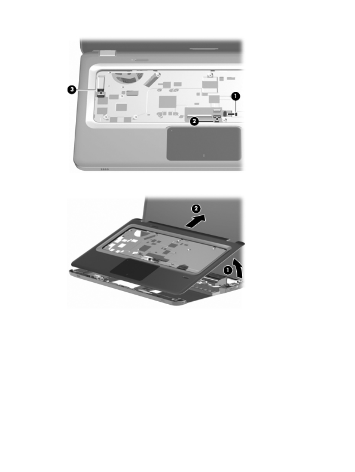
6. Lift the rear edge of the top cover (1) until it rests at an angle, and then remove the top cover (2).
Reverse this procedure to install the top cover.
54 Chapter 4 Removal and replacement procedures
Page 63

Power button board
Description Spare part number
Power button board (includes cable) 603682–001
Before removing the power button board:
1. Shut down the computer. If you are unsure whether the computer is off or in Hibernation, turn the
computer on, and then shut it down through the operating system.
2. Disconnect all external devices connected to the computer.
3. Disconnect the power from the computer by first disconnecting the power cord from the AC outlet
and then disconnecting the AC adapter from the computer.
4. Remove the following components:
a.
Battery on page 40
b.
Hard drive cover on page 41
c.
Hard drive on page 42
d.
Optical drive on page 49
e.
Keyboard on page 50
f.
Top cover on page 52
To remove the power button board:
1. Turn the top cover upside down with the front toward you.
2. Remove the two screws (1) that secure the power button board to the top cover.
Component replacement procedures
55
Page 64

3.
Remove the power button board (2) and cable.
Reverse this procedure to install the power button board.
56 Chapter 4 Removal and replacement procedures
Page 65

Touchscreen display assembly
NOTE: The display assembly includes a webcam, two microphones, and two wireless antenna
transceivers and cables.
Description Spare part number
TouchScreen HD display assembly with etched finish with webcam and two microphones 631019-001
Before removing the display assembly:
1. Shut down the computer. If you are unsure whether the computer is off or in Hibernation, turn the
computer on, and then shut it down through the operating system.
2. Disconnect all external devices connected to the computer.
3. Disconnect the power from the computer by first disconnecting the power cord from the AC outlet
and then disconnecting the AC adapter from the computer.
4. Remove the following components:
a.
Battery on page 40
b.
Hard drive cover on page 41
c.
Hard drive on page 42
d.
WLAN module on page 44
e.
Optical drive on page 49
f.
Keyboard on page 50
g.
Top cover on page 52
To remove the Touchscreen display assembly:
1. Remove the WLAN cables (1) from under the system board.
2. Disconnect the display panel cable (2) from the system board.
Component replacement procedures
57
Page 66

3.
Disconnect the touchscreen cable (3) from the system board.
CAUTION: Support the display assembly when removing the following screws. Failure to
support the display assembly might result in damage to the display assembly and other computer
components.
4. Remove the three screws (1) that secure the display assembly to the computer.
5. Remove the Touchscreen display assembly (2).
6. To replace the display enclosure or any of the display assembly internal components, remove the
following:
●
Two rubber screw covers on the display bezel bottom edge (1). The display rubber screw
covers are included in the Display Rubber Kit, spare part number 603659-001.
●
Two screws (2).
58 Chapter 4 Removal and replacement procedures
Page 67

7. To remove the hinge covers, pop off the cover from each hinge.
8. Pry the display panel from the display enclosure (1) by working your way around the perimeter of
the panel using a flat head screwdriver.
9.
Separate the display panel from the display enclosure (2).
10. Disconnect the display logo cable (3) from the display panel cable.
Component replacement procedures
59
Page 68

11.
Remove the display enclosure. The Touchscreen display enclosure spare part number is 603663–
001.
12. To replace the display hinges, remove the six screws (1) that secure the display hinges to the top
of the display panel.
13. Remove the three screws (2) on the side of each display hinge.
14. Remove the display hinge (3). The display hinge is available in the Display Hinge Kit, spare part
number 603664-001.
60 Chapter 4 Removal and replacement procedures
Page 69

15.
To remove the display panel cable, remove the adhesive plastic strip (1) from the display panel
cable, and then disconnect the cable (2). Lift and remove the cable (3). The Touchscreen Display
Cable Kit is spare part number 603655-001.
Reverse this procedure to reassemble and install the display assembly.
Component replacement procedures
61
Page 70

BrightView display assembly
NOTE: The display assembly includes two wireless antenna transceivers and cables.
Description Spare part number
For use with computer models with black finish and WiMax 629279-001
For use with computer models with etched finish and WiMax 629280-001
For use with computer models with black finish 603647-001
For use with computer models with chrome finish 603650-001
For use with computer models with etched finish 595131-001
For use with computer models with midnight blue finish 615932-001
For use with computer models with shell white finish 603648-001
For use with computer models with Sonoma red finish 603649-001
Before removing the BrightView display assembly:
1. Shut down the computer. If you are unsure whether the computer is off or in Hibernation, turn the
computer on, and then shut it down through the operating system.
2. Disconnect all external devices connected to the computer.
3. Disconnect the power from the computer by first disconnecting the power cord from the AC outlet
and then disconnecting the AC adapter from the computer.
4.
Remove the following components:
a.
Battery on page 40
b.
Hard drive cover on page 41
c.
Hard drive on page 42
d.
WLAN module on page 44
e.
Optical drive on page 49
f.
Keyboard on page 50
g.
Top cover on page 52
To remove the BrightView display assembly:
1.
Remove the WLAN cables (1) from under the system board.
62 Chapter 4 Removal and replacement procedures
Page 71

2.
Disconnect the display panel cable (2) from the system board.
CAUTION: Support the display assembly when removing the following screws. Failure to
support the display assembly might result in damage to the display assembly and other computer
components.
3.
Remove the three screws (1) that secure the display assembly to the computer.
4. Remove the BrightView display assembly (2).
5.
To replace the display bezel or any of the display assembly internal components, remove the
following:
●
Two rubber screw covers on the display bezel bottom edge (1).
●
Two screws (2). The display rubber screw covers are included in the Display Rubber Kit,
spare part number 603659–001.
Component replacement procedures
63
Page 72

6. Remove the hinge covers by popping off the cover from each hinge.
7. Flex the inside edges of the top edge (1), the left and right sides (2), and the bottom edge (3) of
the display bezel until the bezel disengages from the display enclosure.
64 Chapter 4 Removal and replacement procedures
Page 73

8.
Remove the display bezel (4). The display bezel is available using spare part number
603651-001.
9. To replace the display panel, remove the six screws (1) from the display hinges.
10. Separate the display panel from the display enclosure (2), and then disconnect the display LED
cable (3) from the display panel cable. The display panel spare part number is 559130-001.
11. To replace the display hinges, remove the three screws (1) that secure each display hinge to the
display panel.
Component replacement procedures
65
Page 74

12.
Remove the display hinges (2). The display hinges are available in the BrightView Display Hinge
Kit, spare part 603656-001. The display hinge screws are available in the Display Screw Kit,
spare part number 603658-001.
13. To remove the display panel cable, remove the adhesive plastic strip (1) from the display panel
cable, and then disconnect the cable (2). Lift and remove the cable (3). The BrightView Display
Cable Kit is spare part number 603657-001. The BrightView Display Cable Kit with WiMAX is
spare part number 629284-001.
66 Chapter 4 Removal and replacement procedures
Page 75
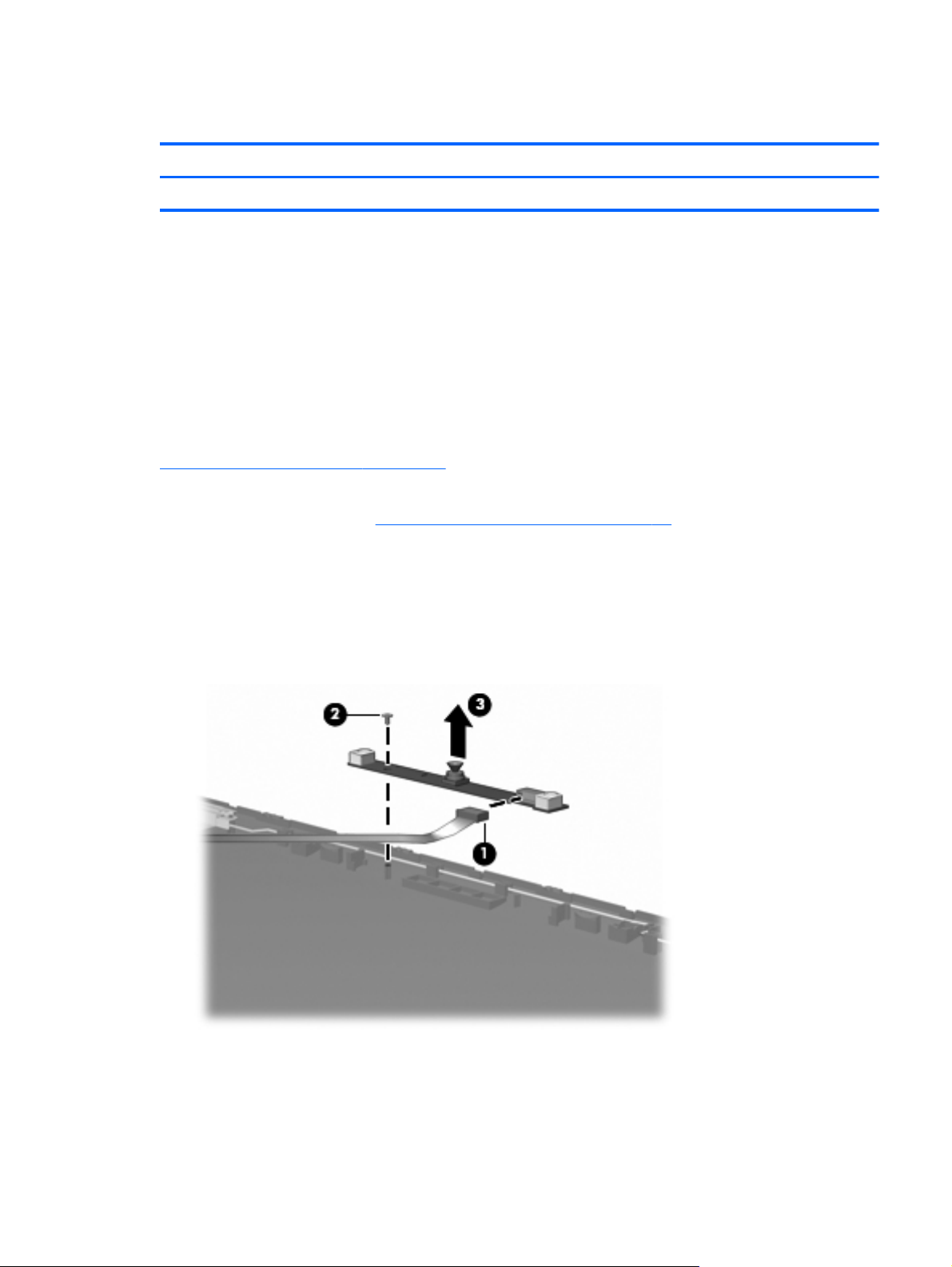
Webcam/microphone module
Description Spare part number
Webcam/microphone module (includes cable) 603660–001
Before removing the webcam/microphone module:
1. Shut down the computer. If you are unsure whether the computer is off or in Hibernation, turn the
computer on, and then shut it down through the operating system.
2. Disconnect all external devices connected to the computer.
3. Disconnect the power from the computer by first disconnecting the power cord from the AC outlet
and then disconnecting the AC adapter from the computer.
To access the BrightView webcam/microphone module, remove the display bezel. For instructions, see
BrightView display assembly on page 62.
To access the Touchscreen webcam/microphone module, remove the display panel from the display
enclosure. For instructions, see
To replace the webcam/microphone module:
Touchscreen display assembly on page 57.
1. Disconnect the webcam/microphone module cable (1) from the webcam/microphone module.
2. Remove the screw securing the webcam/microphone module to the display enclosure (2).
3. Release the webcam/microphone module from the display enclosure (3).
Reverse this procedure to install the webcam/microphone module.
Component replacement procedures
67
Page 76

Bluetooth module
NOTE: The Bluetooth module spare part kit does not include a Bluetooth module cable. The Bluetooth
module cable spare part number is 603645-001.
Description Spare part number
Bluetooth module 537921–001
Before removing the Bluetooth module:
1. Shut down the computer. If you are unsure whether the computer is off or in Hibernation, turn the
computer on, and then shut it down through the operating system.
2. Disconnect all external devices connected to the computer.
3. Disconnect the power from the computer by first disconnecting the power cord from the AC outlet
and then disconnecting the AC adapter from the computer.
4. Remove the following components:
a.
Battery on page 40
b.
Hard drive cover on page 41
c.
Hard drive on page 42
d.
Optical drive on page 49
e.
Keyboard on page 50
f.
Top cover on page 52
g.
Touchscreen display assembly on page 57 or BrightView display assembly on page 62
To remove the Bluetooth module:
1. Disconnect the Bluetooth module cable (1) from the system board.
68 Chapter 4 Removal and replacement procedures
Page 77

2.
Slide the Bluetooth module out of the slot and remove the module (2) from the computer.
Reverse this procedure to install the Bluetooth module.
Component replacement procedures
69
Page 78

USB board
Description Spare part number
USB board (includes cable) 603683–001
Before removing the USB board:
1. Shut down the computer. If you are unsure whether the computer is off or in Hibernation, turn the
computer on, and then shut it down through the operating system.
2. Disconnect all external devices connected to the computer.
3. Disconnect the power from the computer by first disconnecting the power cord from the AC outlet
and then disconnecting the AC adapter from the computer.
4. Remove the following components:
a.
b.
c.
Battery on page 40
Hard drive cover on page 41
Hard drive on page 42
d.
Optical drive on page 49
e.
Keyboard on page 50
f.
Top cover on page 52
g.
Touchscreen display assembly on page 57 or BrightView display assembly on page 62
To remove the USB board (right-side):
1. Disconnect the USB board cable (1) from the LIF connector on the system board.
2. Remove the screws (2) that secures the USB board to the base enclosure.
70 Chapter 4 Removal and replacement procedures
Page 79

3.
Remove the USB board (3) from the base enclosure.
To remove the USB board (left-side):
1. Disconnect the USB board cable (1) from the LIF connector on the system board
2. Remove the USB cable from the clips (2) attaching the cable to the base enclosure.
3. Remove the USB board from the base enclosure (3).
Reverse this procedure to install the USB board.
Component replacement procedures
71
Page 80

Power connector
Description Spare part number
Power connector 603692–001
Before removing the power connector cable:
1. Shut down the computer. If you are unsure whether the computer is off or in Hibernation, turn the
computer on, and then shut it down through the operating system.
2. Disconnect all external devices connected to the computer.
3. Disconnect the power from the computer by first disconnecting the power cord from the AC outlet
and then disconnecting the AC adapter from the computer.
4. Remove the following components:
a.
Battery on page 40
b.
Hard drive cover on page 41
c.
Hard drive on page 42
d.
Optical drive on page 49
e.
Keyboard on page 50
f.
Top cover on page 52
g.
Touchscreen display assembly on page 57 or BrightView display assembly on page 62
h.
USB board on page 70
To remove the power connector cable:
1. Remove the screw (1) that secures the power connector and bracket to the base enclosure.
72 Chapter 4 Removal and replacement procedures
Page 81

2.
Remove the power connector bracket (2).
3.
Disconnect the power cable (1) from the system board and release the cable from the clips built
into the base enclosure.
4. Remove the power connector (2) from the clip built into the base enclosure.
Reverse this procedure to install the power connector and cable.
Component replacement procedures
73
Page 82

System board
NOTE: The system board spare kit includes replacement thermal material.
Description Spare part number
For use with computer models equipped with a graphics subsystem with discrete memory 633554-001
For use with computer models equipped with a graphics subsystem with UMA memory 633555-001
Before removing the system board:
1.
Shut down the computer. If you are unsure whether the computer is off or in Hibernation, turn the
computer on, and then shut it down through the operating system.
2. Disconnect all external devices connected to the computer.
3. Disconnect the power from the computer by first disconnecting the power cord from the AC outlet
and then disconnecting the AC adapter from the computer.
4. Remove the following components:
a.
Battery on page 40
b.
Hard drive cover on page 41
c.
Hard drive on page 42
d.
Optical drive on page 49
e.
Keyboard on page 50
f.
Top cover on page 52
g.
Touchscreen display assembly on page 57 or BrightView display assembly on page 62
When replacing the system board, be sure that the following components are removed from the
defective system board and installed on the replacement system board:
●
RTC battery on page 48
●
Memory module on page 46
●
WLAN module on page 44
●
Fan/heat sink assembly on page 77
●
Processor on page 80
74 Chapter 4 Removal and replacement procedures
Page 83

To remove the system board:
1. Disconnect the following cables from the system board:
●
Left-side USB board cable (1)
●
Bluetooth cable (2)
●
Speaker cable (3)
●
Right-side USB board cable (1)
●
Power connector cable (2)
●
Optical drive cable
Component replacement procedures
75
Page 84

2. Lift up on the right side of the system board until it is at approximately a 45-degree angle (1).
3.
Lift the system board to the right and up and out of the base enclosure (2).
Reverse this procedure to install the system board.
76 Chapter 4 Removal and replacement procedures
Page 85

Fan/heat sink assembly
NOTE: The fan/heat sink assembly spare kit includes replacement thermal material.
Description Spare part number
For use with computer models equipped with a graphics subsystem with discrete memory 634454-001
For use with computer models equipped with a graphics subsystem with UMA memory 634455-001
NOTE: To properly ventilate the computer, allow at least a 7.6-cm (3-inch) clearance on the right side
and rear panel of the computer. The computer uses an electric fan for ventilation. The fan is controlled
by a temperature sensor and is designed to turn on automatically when high temperature conditions
exist. These conditions are affected by high external temperatures, system power consumption, power
management/battery conservation configurations, battery fast charging, and software requirements.
Exhaust air is displaced through the ventilation grill located on the left side of the computer.
Before removing the fan/heat sink assembly:
1. Shut down the computer. If you are unsure whether the computer is off or in Hibernation, turn the
computer on, and then shut it down through the operating system.
2. Disconnect all external devices connected to the computer.
3. Disconnect the power from the computer by first disconnecting the power cord from the AC outlet
and then disconnecting the AC adapter from the computer.
4. Remove the following components:
a.
Battery on page 40
b.
Hard drive cover on page 41
c.
Hard drive on page 42
d.
Optical drive on page 49
e.
Keyboard on page 50
f.
Top cover on page 52
g.
Touchscreen display assembly on page 57 or BrightView display assembly on page 62
h.
USB board on page 70
i.
System board on page 74
To remove the fan/heat sink assembly:
1. Turn the system board upside down, with the fan toward you
2. Disconnect the fan cable (1) from the system board.
3. Loosen the seven captive screws (2) and (3) that secure the fan/heat sink assembly to the system
board.
Component replacement procedures
77
Page 86

NOTE: The screws (3) that secure the section of the fan/heat sink assembly that services the
graphics subsystem memory component are present only on computer models equipped with a
graphics subsystem with discrete memory.
NOTE: Due to the adhesive quality of the thermal material located between the fan/heat sink
assembly and system board components, it might be necessary to move the fan/heat sink
assembly from side to side to detach the assembly.
78 Chapter 4 Removal and replacement procedures
Page 87

4.
Remove the fan/heat sink assembly (4).
NOTE: The thermal material must be thoroughly cleaned from the surfaces of the fan/heat sink
assembly and the system board each time the fan/heat sink assembly is removed. Thermal paste is
applied to the fan/heat sink assembly to correspond with components on the system board as
follows: the processor (1) and (2), the Northbridge chip (3) and (4), and the graphics subsystem
chip (5) and (6). Replacement thermal material is included with all fan/heat sink assembly, system
board, and processor spare part kits.
Reverse this procedure to install the fan/heat sink assembly.
Component replacement procedures
79
Page 88

Processor
NOTE: The processor spare part kit includes thermal material.
Description Spare part number
Intel Core i7-2820QM 2.30-GHz (turbo up to 3.40-GHz) processor, 8-MB L2 cache, 1600 MHz,
45 W
Intel Core i7-2720QM 2.20-GHz (turbo up to 3.30-GHz) processor, 6-MB L2 cache, 1600 MHz,
45 W
Intel Core I7-2630QM 2.00-GHz (turbo up to 2.90-GHz) processor, 6-MB L2 cache, 1600 MHz,
45 W
634694-001
631254-001
635501-001
Before removing the processor:
1.
Shut down the computer. If you are unsure whether the computer is off or in Hibernation, turn the
computer on, and then shut it down through the operating system.
2. Disconnect all external devices connected to the computer.
3. Disconnect the power from the computer by first disconnecting the power cord from the AC outlet
and then disconnecting the AC adapter from the computer.
4. Remove the following components:
a.
Battery on page 40
b.
Hard drive cover on page 41
c.
Hard drive on page 42
d.
Optical drive on page 49
e.
Keyboard on page 50
f.
Top cover on page 52
g.
Touchscreen display assembly on page 57 or BrightView display assembly on page 62
h.
USB board on page 70
i.
System board on page 74
j.
Fan/heat sink assembly on page 77
To replace the processor:
1. Turn the processor locking screw (1) one-half turn counterclockwise until you hear a click.
80 Chapter 4 Removal and replacement procedures
Page 89

2.
Lift the processor (2) straight up and remove it.
NOTE: The gold triangle (3) on the processor must be aligned with the triangle icon (4)
embossed on the processor socket when installing the processor.
Reverse this procedure to install the processor.
Component replacement procedures
81
Page 90

Speaker assembly
Description Spare part number
Speaker assembly 603694–001
Before removing the speaker assembly:
1. Shut down the computer. If you are unsure whether the computer is off or in Hibernation, turn the
computer on, and then shut it down through the operating system.
2. Disconnect all external devices connected to the computer.
3. Disconnect the power from the computer by first disconnecting the power cord from the AC outlet
and then disconnecting the AC adapter from the computer.
4. Remove the following components:
a.
Battery on page 40
b.
Hard drive cover on page 41
c.
Hard drive on page 42
d.
Optical drive on page 49
e.
Keyboard on page 50
f.
Top cover on page 52
g.
Touchscreen display assembly on page 57 or BrightView display assembly on page 62
h.
System board on page 74
To remove the speaker assembly:
1. Remove the three screws (1) securing the speaker assembly to the base enclosure.
2. Disconnect the speaker assembly cable (2) from the system board.
82 Chapter 4 Removal and replacement procedures
Page 91

3.
Remove the speaker assembly (3).
Reverse this procedure to install the speaker assembly.
Speaker assembly
83
Page 92

5 Setup Utility (BIOS)
Starting Setup Utility
Setup Utility is a ROM-based information and customization utility is used even when the Windows
operating system is not working.
NOTE: The Fingerprint Reader (select models only) cannot be used to access Setup Utility.
The utility reports information about the computer and provides settings for startup, security, and other
preferences.
To start Setup Utility:
1.
Open Setup Utility by turning on or restarting the computer. When the Press the ESC key for
Startup Menu screen appears, press the f10 key.
– or –
Open Setup Utility by turning on or restarting the computer. When the Press the ESC key for
Startup Menu screen appears, press the esc key.
2. When the Startup Menu appears, press the f10 key.
Using Setup Utility
Changing the language of Setup Utility
To change the language of Setup Utility:
84 Chapter 5 Setup Utility (BIOS)
Page 93

NOTE: If Setup Utility is not running, begin at step 1. If Setup Utility is running, begin at step 2.
1. Open Setup Utility by turning on or restarting the computer. When the Press the ESC key for
Startup Menu screen appears, press the f10 key.
– or –
Open Setup Utility by turning on or restarting the computer. When the Press the ESC key for
Startup Menu screen appears, press the esc key. When the Startup Menu appears, press the f10
key.
2. Use the arrow keys to select System Configuration > Language, and then press the enter
key.
3. Use the arrow keys to select a language, and then press the enter key.
4. When a confirmation prompt with your language selected is displayed, press the enter key.
5. To save your change and exit Setup Utility, use the arrow keys to select Exit > Exit Saving
Changes, and then press the enter key.
Changes goes into effect immediately.
Navigating and selecting in Setup Utility
Because Setup Utility is not Windows-based, it does not support the TouchPad. Navigation and
selection are by keystroke.
To navigate Setup Utility:
●
Use the arrow keys to choose a menu or a menu item.
●
Use either the arrow keys or the f5 or f6 keys to choose an item in a list or to toggle a field,
for example an Enable/Disable field.
●
Press the enter key to select an item.
●
Press the esc key to close a text box or return to the menu display.
●
Press the f1 key to display additional navigation and selection information.
Displaying system information
Use Setup Utility to view the system time and date and information that identifies the computer.
To display the system information using Setup Utility:
Using Setup Utility
85
Page 94

NOTE: If Setup Utility is running, begin at step 1. If Setup Utility is not running, begin at step 2.
1. Open Setup Utility by turning on or restarting the computer. When the Press the ESC key for
Startup Menu screen appears, press the f10 key.
– or –
Open Setup Utility by turning on or restarting the computer. When the Press the ESC key for
Startup Menu screen appears, press the esc key. When the Startup Menu appears, press the f10
key.
2. Select the Main menu.
3. To exit Setup Utility without changing any settings, use the arrow keys to select Exit > Exit
Discarding Changes, and then press the enter key.
Restoring default settings in Setup Utility
To restore Setup Utility default settings:
NOTE: If Setup Utility is not running, begin at step 1. If Setup Utility is running, begin at step 2.
1. Open Setup Utility by turning on or restarting the computer. When the Press the ESC key for
Startup Menu screen appears, press the f10 key.
– or –
Open Setup Utility by turning on or restarting the computer. When the Press the ESC key for
Startup Menu screen appears, press the esc key. When the Startup Menu appears, press the f10
key.
2.
Use the arrow keys to select Exit > Load Setup Defaults, and then press the enter key.
3.
When the Setup Confirmation screen appears, press the enter key.
4.
To save your change and exit Setup Utility, use the arrow keys to select Exit > Exit Saving
Changes, and then press the enter key.
Setup Utility default settings go into effect when the computer restarts.
NOTE: Your password, security, and language settings are not changed when you restore the factory
default settings.
Exiting Setup Utility
Exit Setup Utility with or without saving changes.
●
To exit Setup Utility and save your changes from the current session:
If the Setup Utility menus are not visible, press the esc key to return to the menu display. Use the
arrow keys to select Exit > Exit Saving Changes, and then press the enter key.
●
To exit Setup Utility without saving your changes from the current session:
86 Chapter 5 Setup Utility (BIOS)
Page 95

If the Setup Utility menus are not visible, press the esc key to return to the menu display. Use the
arrow keys to select Exit > Exit Discarding Changes, and then press the enter key.
After either choice, the computer restarts in Windows.
Setup Utility menus
The menu tables provide an overview of Setup Utility options.
NOTE: Some Setup Utility menu items might not be supported by the computer.
Main menu
Select Function
System information
Security menu
Select Function
Administrator password Enter, change, or delete an administrator password.
Power-On Password Enter, change, or delete a power-on password.
System Configuration menu
Select Function
Language Support Change the language of Setup Utility.
Virtualization Technology (select models only) Enable/disable the processor Virtualization Technology.
●
View and change the system time and date.
●
View identification information about the computer.
●
View specification information about the processor, memory size,
system BIOS, and keyboard controller version (select models only).
LAN Power Saving (select models only) Enable/disable LAN Power Saving. When enabled, saves power when
the computer is in DC mode.
Fan Always On Enabled/disable Fan Always On. When enabled, the computer fan is
always on.
Setup Utility menus
87
Page 96

Select Function
Action Keys Mode Enable/disable the Action Keys.
Boot Options
●
POST (power-on self test) f10 and f12 Delay (sec.)―Set the delay
for the f10 and f12 functions of Setup Utility in intervals of 5
seconds each (0, 5, 10, 15, 20).
●
HP QuickWeb—
◦
Enable/disable the HP QuickWeb Boot Menu during POST.
◦
Delay to boot Windows—Set the delay for the HP QuickWeb
Boot Menu to 2, 3, 5, 10, 15, or 30 seconds.
●
CD-ROM Boot―Enable/disable boot from CD-ROM.
●
Floppy Boot―Enable/disable boot from diskette.
●
Internal Network Adapter Boot―Enable/disable boot from the
internal network adapter.
●
Boot Order―Set the boot order for:
◦
Hard Drive
◦
Internal CD/DVD ROM Drive
◦
USB Diskette on Key/USB Hard Drive
◦
USB CD/DVD ROM Drive
◦
USB Floppy
Diagnostics menu
Select Function
Primary Hard Disk Self Test Run a comprehensive self-test on the hard drive.
Secondary Hard Disk Self Test (select models only) Run a comprehensive self-test on a secondary hard drive.
Memory Test Run a diagnostic test on the system memory.
◦
Network Adapter
88 Chapter 5 Setup Utility (BIOS)
Page 97

6 Specifications
Computer specifications
Metric U.S.
Dimensions
Width 37.8 cm 14.9 in
Depth 24.5 cm 9.6 in
Height (front to back) 3.2 to 3.5 cm 1.3 to 1.4 in
Diagonal 39.6 cm 15.6 in
Weight (with optical drive, hard drive,
and battery)
Input power
Operating voltage 18.5 V dc @ 3.5 A - 65 W
Operating current 3.5 A or 4.74 A
Temperature
Operating (not writing to optical disc) 0°C to 35°C 32°F to 95°F
Operating (writing to optical disc) 5°C to 35°C 41°F to 95°F
Nonoperating -20°C to 60°C -4°F to 140°F
Relative humidity
Operating 10% to 90%
Nonoperating 5% to 95%
Maximum altitude (unpressurized)
Operating -15 m to 3,048 m -50 ft to 10,000 ft
Nonoperating -15 m to 12,192 m -50 ft to 40,000 ft
NOTE: Applicable product safety standards specify thermal limits for plastic surfaces. The computer operates well within this
range of temperatures.
2.5 g to 2.9 kg 5.5 lbs to 6.5 lbs
Computer specifications
89
Page 98

39.6-cm (15.6-inch) display specifications
Number of colors Up to 262,114
Contrast ratio 500:1 (typical)
Brightness 220 nits (typical)
Pitch 0.252 × 0.252 mm
Format 1366 × 768
Configuration RGB vertical stripe
Backlight Edge lit
Character display 80 × 25
Total power consumption 4.7 W
Viewing angle ±45° horizontal, ±15° upper vertical, ±35° lower vertical
(typical)
90 Chapter 6 Specifications
Page 99

Hard drive specifications
1-TB* 750-
GB**
Dimensions
Height 12.5 mm 12.5 mm 9.5 mm 9.5 mm 9.5 mm 9.5 mm 9.5 mm
Length 100.2 mm 100.2 mm 100.2 mm 100.35 mm 100.35 mm 100.35 mm 100.35 mm
Width 69.85 mm 69.85 mm 69.85 mm 69.85 mm 69.85 mm 69.85 mm 69.85 mm
Weight 152 g 152 g 98 g 110 g 110 g 105 g 105 g
Interface
type
Transfer rate
Synchronous
(maximum)
Security ATA
Seek times (typical read, including setting)
Single track 2 ms 2 ms 1.5 ms 1.5 ms 1.5 ms 1.5 ms 1.5 ms
Average (read/
write)
SATA( 3
GB/sec)
97 MB/
sec
security
12/16 ms 12/16 ms 12/13 ms 11/13 ms 11/13 ms 11/13 ms 11/13 ms
SATA (3
GB/sec)
97 MB/
sec
ATA
security
640-GB* 500-GB** 320-GB** 250-GB** 160-GB**
SATA (3
GB/sec)
106 MB/
sec
ATA
security
SATA SATA SATA SATA
1.1 GB/sec
(internal)
ATA security ATA security ATA security ATA security
1.1 GB/sec
(internal)
1.1 GB/sec
(internal)
1.1 GB/sec
(internal)
Maximum 21 ms 21 ms 24 ms 22 ms 22 ms 22 ms 22 ms
Logical
blocks
Disc
rotational
speed
Operating
temperature
*1 TB = 1 trillion bytes when referring to hard drive storage capacity. Actual accessible capacity is less.
**1 GB = 1 billion bytes when referring to hard drive storage capacity. Actual accessible capacity is less.
NOTE: Certain restrictions and exclusions apply. Contact technical support for details.
1,953,52
5,168
5200 and
5400-rpm
0°C to 60°C (32°F to 140°F)
1,465,14
9,168
5200 and
5400-rpm
1,250,26
3,728
5400 and
7200-rpm
976,773,168 625,142,448 488,397,168 312,581,808
5400 and
7200-rpm
7200-rpm 7200-rpm 7200-rpm
Hard drive specifications
91
Page 100

LightScribe DVD±R/RW SuperMulti DL Drive specifications
Applicable disc Read: Write:
CD-DA, CD+(E)G, CD-MIDI, CDTEXT,
CD-ROM, CD-ROM XA, MIXED
MODE CD, CD-I, CD-I Bridge (PhotoCD, Video CD), Multisession CD
(Photo-CD, CD-EXTRA, Portfolio,
CDR, CD-RW), CD-R, CD-RW, DVDROM (DVD-5, DVD-9, DVD-10,
DVD-18), DVD-R, DVD-RW, DVD+R,
DVD+RW, DVD-RAM
Access time CD DVD
Random <175 ms <230 ms
Full stroke < 285 ms < 335 ms
Cache buffer 2 MB
Data transfer rate
24X CD-ROM 3,600 KB/sec
8X DVD 10,800 KB/sec
24X CD-R 3,600 KB/sec
8X DVD+R 10,800 KB/sec
4X DVD+RW 5,400 KB/sec
CD-R and CD-RW DVD+R, DVD
+RW, DVD-R, DVD-RW, DVD-RAM
8X DVD-R 10,800 KB/sec
4X DVD-RW 5,400 KB/sec
2.4X DVD+R(9) 2,700 KB/sec
5X DVD-RAM 6,750 KB/sec
Transfer mode Multiword DMA Mode
92 Chapter 6 Specifications
 Loading...