

Page 1

HP Pavilion dv3 Entertainment PC
Maintenance and Service Guide
Page 2

© Copyright 2008 Hewlett-Packard
Development Company, L.P.
Bluetooth is a trademark owned by its
proprietor and used by Hewlett-Packard
Company under license. AMD Athlon and
AMD Turion are trademarks of Advanced
Micro Devices, Inc. Microsoft, Windows, and
Windows Vista are U.S. registered
trademarks of Microsoft Corporation. SD
Logo is a trademark of its proprietor.
The information contained herein is subject
to change without notice. The only
warranties for HP products and services are
set forth in the express warranty statements
accompanying such products and services.
Nothing herein should be construed as
constituting an additional warranty. HP shall
not be liable for technical or editorial errors
or omissions contained herein.
First Edition: December 2008
Document Part Number: 501558-001
Page 3

Safety warning notice
WARNING! To reduce the possibility of heat-related injuries or of overheating the computer, do not
place the computer directly on your lap or obstruct the computer air vents. Use the computer only on a
hard, flat surface. Do not allow another hard surface, such as an adjoining optional printer, or a soft
surface, such as pillows or rugs or clothing, to block airflow. Also, do not allow the AC adapter to contact
the skin or a soft surface, such as pillows or rugs or clothing, during operation. The computer and the
AC adapter comply with the user-accessible surface temperature limits defined by the International
Standard for Safety of Information Technology Equipment (IEC 60950).
iii
Page 4

iv Safety warning notice
Page 5

Table of contents
1 Product description
2 External component identification
Top components ................................................................................................................................... 4
Display components ............................................................................................................ 4
Buttons and fingerprint reader (select models only) ............................................................ 5
Keys ..................................................................................................................................... 6
Lights ................................................................................................................................... 8
TouchPad ............................................................................................................................ 9
Front components .............................................................................................................................. 10
Right-side components ....................................................................................................................... 10
Left-side components ......................................................................................................................... 11
Bottom components ........................................................................................................................... 12
3 Illustrated parts catalog
Serial number location ........................................................................................................................ 13
Computer major components ............................................................................................................. 14
Display assembly components ........................................................................................................... 17
Plastics Kit .......................................................................................................................................... 19
Mass storage devices ......................................................................................................................... 20
Miscellaneous parts ............................................................................................................................ 21
Sequential part number listing ............................................................................................................ 22
4 Removal and replacement procedures
Preliminary replacement requirements ............................................................................................... 24
Tools required .................................................................................................................... 24
Service considerations ....................................................................................................... 24
Plastic parts ....................................................................................................... 24
Cables and connectors ..................................................................................... 25
Drive handling ................................................................................................... 25
Grounding guidelines ......................................................................................................... 26
Electrostatic discharge damage ........................................................................ 26
Packaging and transporting guidelines ............................................. 27
v
Page 6

Workstation guidelines ..................................................................... 27
Equipment guidelines ....................................................................... 28
Unknown user password ................................................................................................... 29
Component replacement procedures ................................................................................................. 30
Serial number .................................................................................................................... 30
Computer feet .................................................................................................................... 31
Battery ............................................................................................................................... 32
WLAN module .................................................................................................................... 33
Optical drive ....................................................................................................................... 35
Memory module ................................................................................................................. 36
Hard drive .......................................................................................................................... 38
Keyboard and switch cover ................................................................................................ 40
Display assembly ............................................................................................................... 43
Top cover ........................................................................................................................... 49
Fingerprint reader board .................................................................................................... 51
System board ..................................................................................................................... 52
Speakers ............................................................................................................................ 54
Bluetooth module ............................................................................................................... 55
RTC battery ....................................................................................................................... 57
Fan/heat sink assembly ..................................................................................................... 58
Processor ........................................................................................................................... 60
5 Setup Utility
Starting the Setup Utility ..................................................................................................................... 62
Changing the language of the Setup Utility ........................................................................................ 62
Navigating and selecting in the Setup Utility ...................................................................................... 63
Displaying system information ............................................................................................................ 63
Restoring default settings in the Setup Utility ..................................................................................... 63
Exiting the Setup Utility ...................................................................................................................... 64
Setup Utility menus ............................................................................................................................ 64
6 Specifications
Computer specifications ..................................................................................................................... 66
13.3-inch, WXGA, BrightView display specifications .......................................................................... 67
Hard drive specifications .................................................................................................................... 68
DVD±RW and CD-RW SuperMulti Double-Layer Combo Drive specifications .................................. 69
System DMA specifications ................................................................................................................ 70
System memory map specifications ................................................................................................... 70
System interrupt specifications ........................................................................................................... 71
Main menu ......................................................................................................................... 64
Security menu .................................................................................................................... 64
System Configuration menu .............................................................................................. 65
Diagnostics menu .............................................................................................................. 65
vi
Page 7

System I/O address specifications ..................................................................................................... 72
7 Screw listing
Phillips PM2.0×2.0 broadhead screw ................................................................................................. 74
Phillips PM2.0×3.0 captive screw ....................................................................................................... 75
Phillips PM2.0×4.0 screw ................................................................................................................... 76
Phillips PM2.0×8.0 captive screw ....................................................................................................... 77
Phillips PM2.5×4.0 screw ................................................................................................................... 78
Phillips PM2.5×5.0 screw ................................................................................................................... 80
Phillips PM2.5×6.0 captive screw ....................................................................................................... 82
Phillips PM2.5×7.0 screw ................................................................................................................... 83
8 Backup and recovery
Recovering system information .......................................................................................................... 85
Creating recovery discs ..................................................................................................... 85
Backing up your information .............................................................................................. 86
Using system restore points .............................................................................................. 87
Performing a recovery ....................................................................................................... 88
When to back up ............................................................................................... 86
Backup suggestions .......................................................................................... 86
When to create restore points ........................................................................... 87
Create a system restore point ........................................................................... 87
Restore to a previous date and time ................................................................. 87
Recovering from the recovery discs .................................................................. 88
Recovering from the dedicated recovery partition (select models only) ............ 88
9 Connector pin assignments
Audio-in (microphone) ........................................................................................................................ 90
Audio-out (headphone) ....................................................................................................................... 90
External monitor ................................................................................................................................. 90
RJ-11 (modem) .................................................................................................................................. 92
RJ-45 (network) ...............................................................................................................
Universal Serial Bus ........................................................................................................................... 93
10 Power cord set requirements
Requirements for all countries or regions ........................................................................................... 94
Requirements for specific countries or regions .................................................................................. 95
11 Recycling
Battery ................................................................................................................................................ 96
Display ................................................................................................................................................ 96
................... 92
vii
Page 8

Index ................................................................................................................................................................. 102
viii
Page 9

1 Product description
Category Description
Product Name HP Pavilion dv3 Entertainment PC
Processors AMD Turion™ Ultra Dual-Core ZM-86 2.40-GHz processor (35W, 2-MB L2 cache)
AMD Turion Ultra Dual-Core ZM-84 2.30-GHz processor (35W, 2-MB L2 cache)
AMD Turion Ultra Dual-Core ZM-82 2.20-GHz processor (35W, 2-MB L2 cache)
AMD Turion Dual-Core RM-74 2.20-GHz processor (35W, 1-MB L2 cache)
AMD Turion Dual-Core RM-72 2.10-GHz processor (35W, 1-MB L2 cache)
AMD Athlon™ X2 Dual-Core QL-64 2.10-GHz processor (35W, 1-MB L2 cache)
AMD Athlon™ X2 Dual-Core QL-62 2.00-GHz processor (35W, 1-MB L2 cache)
Chipset Southbridge: SB700
Graphics ATI Radeon HD 3200 Graphics
Panel 13.3-inch, WXGA with BrightView
Memory 2 SODIMM slots
Customer-accessible/upgradable
Supports up to 8 GB of system RAM
Support for DDR2 dual-channel 800-MHz
Support for:
8192 MB total system memory (4096 × 2)
●
4096 MB total system memory (2048 × 2)
●
2048 MB total system memory (1024 × 2)
●
1024 MB total system memory (1024 × 1, 512 × 2)
●
Hard drives Support for 9.5-mm, 2.5-inch hard drives
Support for HP ProtectSmart Hard Drive Protection
Support for solid state drive (SDD)
Serial ATA
1
Page 10

Category Description
Support for the following drives:
500-GB, 5400-rpm
●
400-GB, 5400-rpm
●
320-GB, 5400-rpm
●
250-GB, 5400-rpm
●
160-GB, 5400-rpm
●
Optical drives MultiBay II
Serial ATA
9.5-mm tray-load or slot-load
Support for:
DVD±RW and CD-RW SuperMulti Double-Layer Combo Drive
●
Camera Low-light VGA camera with activity light
Fixed (no tilt)
Microphone Dual-array digital microphones
Audio HP-branded Altec Lansing speakers
Ethernet Integrated 10/100/1000 network interface card (NIC)
Ethernet cable not included
Wireless Integrated wireless local area network (WLAN) options by way of wireless module:
Broadcom 4322AGN 802.11a/b/g/n
Broadcom 802.11b/g
External media cards Secure Digital (SD) Memory Card, MultiMediaCard (MMC), Memory Stick (MS), Memory Stick
Support for miniature versions of SD, MMC, and MS Duo with adapter (adapter is not included)
ExpressCard slot
Ports Audio-in (stereo microphone)
Audio-out (stereo headphone)
Consumer infrared
Extended serial advanced technology (eSATA)
High Definition Multimedia Interface (HDMI) version 1.3 supporting 1080p with High-bandwidth
RJ-45 (Ethernet, includes link and activity lights)
USB (2)
Pro (MSP), xD-Picture Card (XD)
Digital Content Protection (HDCP) key
VGA (Dsub, 15-pin) supporting 1600 × 1200 external resolution @ 75 Hz, hot plug/unplug, and
2-pin, 65-W AC power
2 Chapter 1 Product description
autodetect for correct output to wide-aspect vs. standard-aspect video
Page 11

Category Description
Docking No docking
Keyboard/pointing devices 33.80-cm (13.3-inch) keyboard
TouchPad
2-way scroll
Taps enabled as default
Power requirements
65-W HP Smart Adapter with localized cable plug support (2-wire plug with ground pin,
Security Security cable slot
Fingerprint reader with Digital Persona software support
Operating system Preinstalled:
Windows Vista® Business (32-bit)
Windows Vista Ultimate (64-bit)
Windows Vista Premium (32-bit and 64-bit)
Serviceability End-user replaceable parts:
AC adapter
Battery (system)
Hard drive
Memory module
Optical drive
9-cell, 83-Wh, 2.55-Ah Li-ion battery
●
6-cell, 55-Wh, 2.55-Ah Li-ion battery
●
supports 2-pin DC connector)
3
Page 12
2 External component identification
Top components
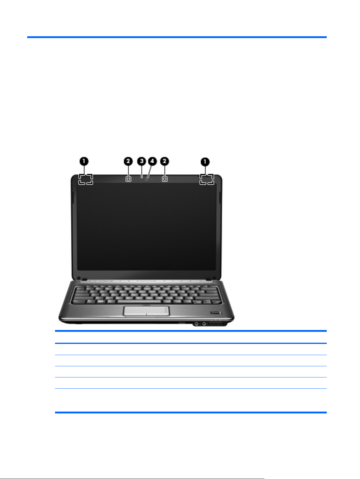
Display components
Component Description
(1) Wireless antennae (2)* Send and receive wireless signals to communicate with WLANs.
(2) Internal microphones (2) Record sound.
(3) Webcam light On: The webcam is in use.
(4) Webcam Records audio and video and captures still photographs.
*The antennae are not visible from the outside of the computer. For optimal transmission, keep the areas immediately around
the antennae free from obstructions. To see wireless regulatory notices, refer to the section of the Regulatory, Safety and
Environmental Notices that applies to your country or region. These notices are located in Help and Support.
4 Chapter 2 External component identification
Page 13
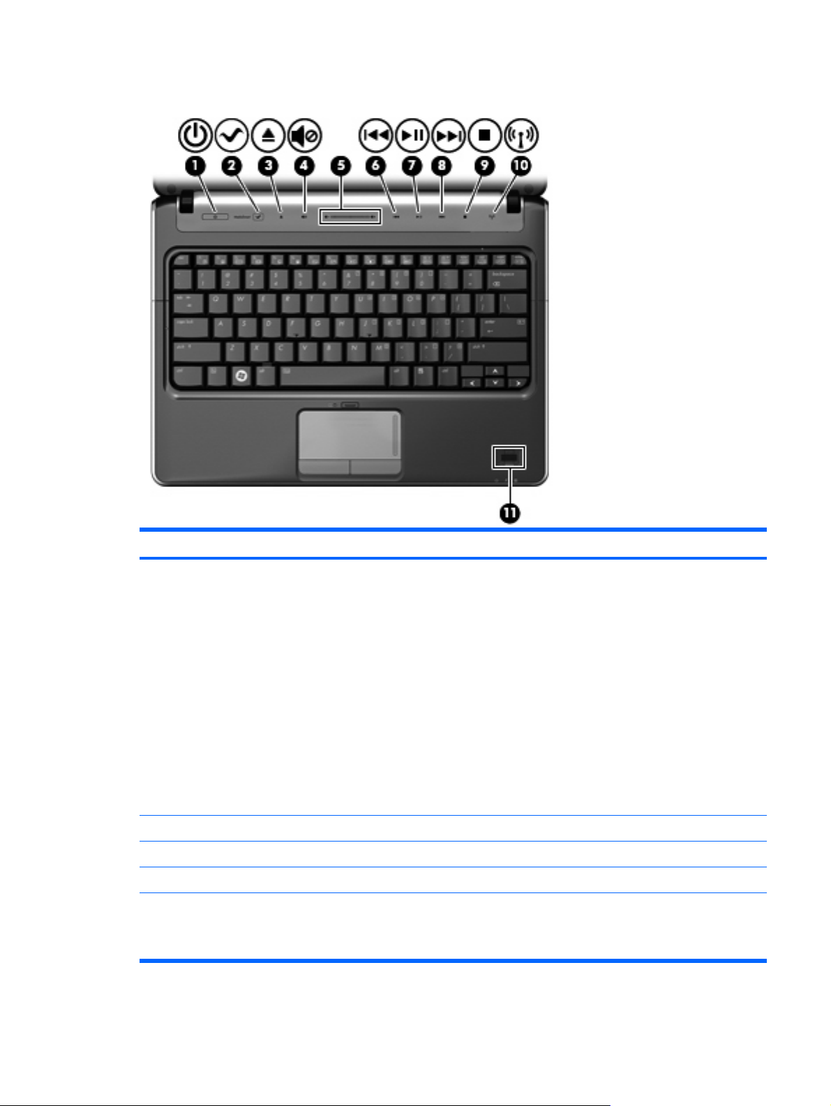
Buttons and fingerprint reader (select models only)
Component Description
(1) Power button*
(2) MediaSmart button Launches HP MediaSmart when the computer is on.
(3) Eject button Ejects the CD, DVD, or BD.
(4) Volume mute button Mutes and restores speaker sound.
(5) Volume scroll zone Adjusts speaker volume. Slide your finger to the left to decrease
When the computer is off, press the button to turn on the
●
computer.
When the computer is on, press the button briefly to initiate
●
Sleep.
When the computer is in the Sleep state, press the button
●
briefly to exit Sleep.
When the computer is in Hibernation, press the button briefly
●
to exit Hibernation.
If the computer has stopped responding and Windows® shutdown
procedures are ineffective, press and hold the power button for at
least 5 seconds to turn off the computer.
To learn more about your power settings, select Start > Control
Panel > System and Maintenance > Power Options.
volume and to the right to increase volume. You can also tap the
minus (-) sign on the scroll zone to decrease volume, or tap the
plus (+) sign on the scroll zone to increase volume.
Top components 5
Page 14
Component Description
(6) Previous/rewind button
(7) Play/pause button Plays or pauses media.
(8) Next/fast forward button
(9) Stop button Stops playback.
(10) Wireless button Turns the wireless feature on or off but does not create a wireless
(11) Fingerprint reader (select models only) Allows a fingerprint logon to Windows, instead of a password
*This table describes factory settings. For information about changing factory settings, refer to the user guides located in Help
and Support.
Plays the previous track or chapter when the button is
●
pressed once.
Rewinds media when the button is pressed in combination
●
with the fn key.
Plays the next track or chapter when the button is pressed
●
once.
Fast forwards media when pressed in combination with the
●
fn key.
connection.
NOTE: To establish a wireless connection, a wireless network
must already be set up.
logon.
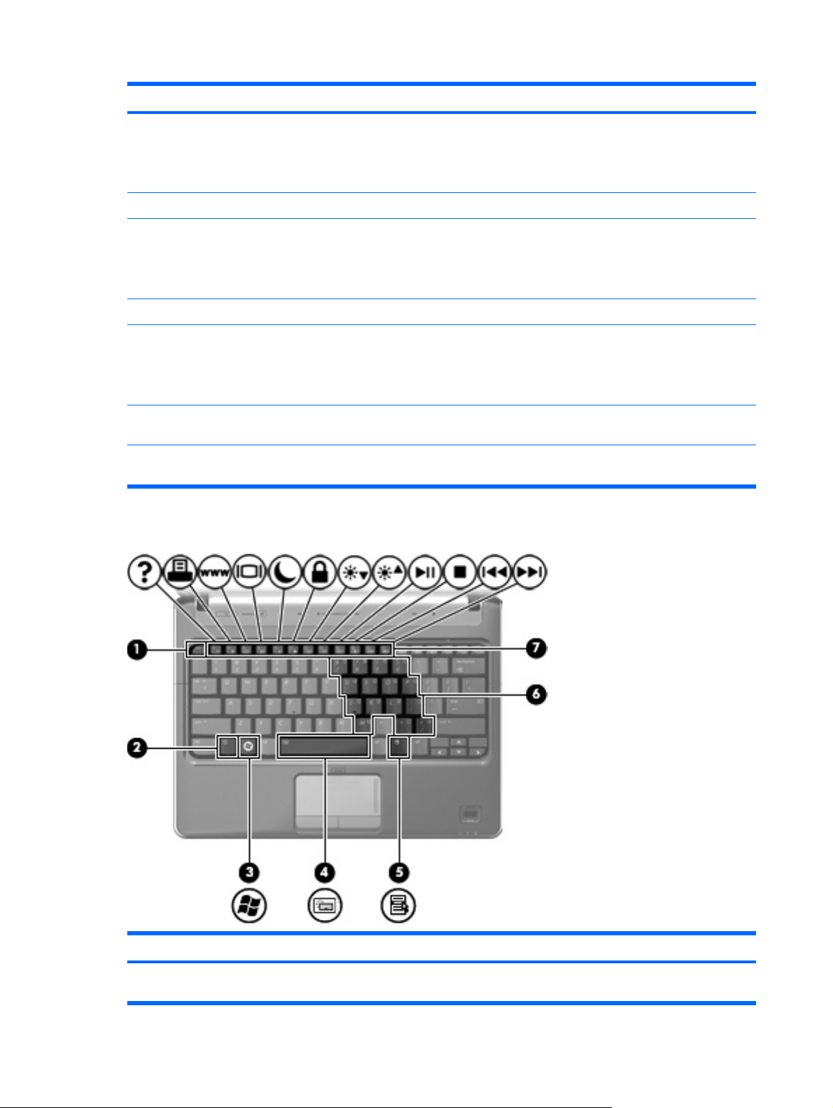
Keys
Component Description
(1) esc key Displays system information when pressed in combination with
6 Chapter 2 External component identification
the fn key.
Page 15

Component Description
(2) fn key Executes frequently used system functions when pressed in
combination with a function key or the esc key.
(3) Windows logo key Displays the Windows Start menu.
(4) Spacebar Turns the keyboard lights on and off when pressed in combination
with the fn key (select models only).
(5) Windows applications key Displays a shortcut menu for items beneath the pointer.
(6) Embedded numeric keypad keys Can be used like the keys on an external numeric keypad.
(7) Function keys Execute frequently used system functions when pressed in
combination with the fn key.
Top components 7
Page 16
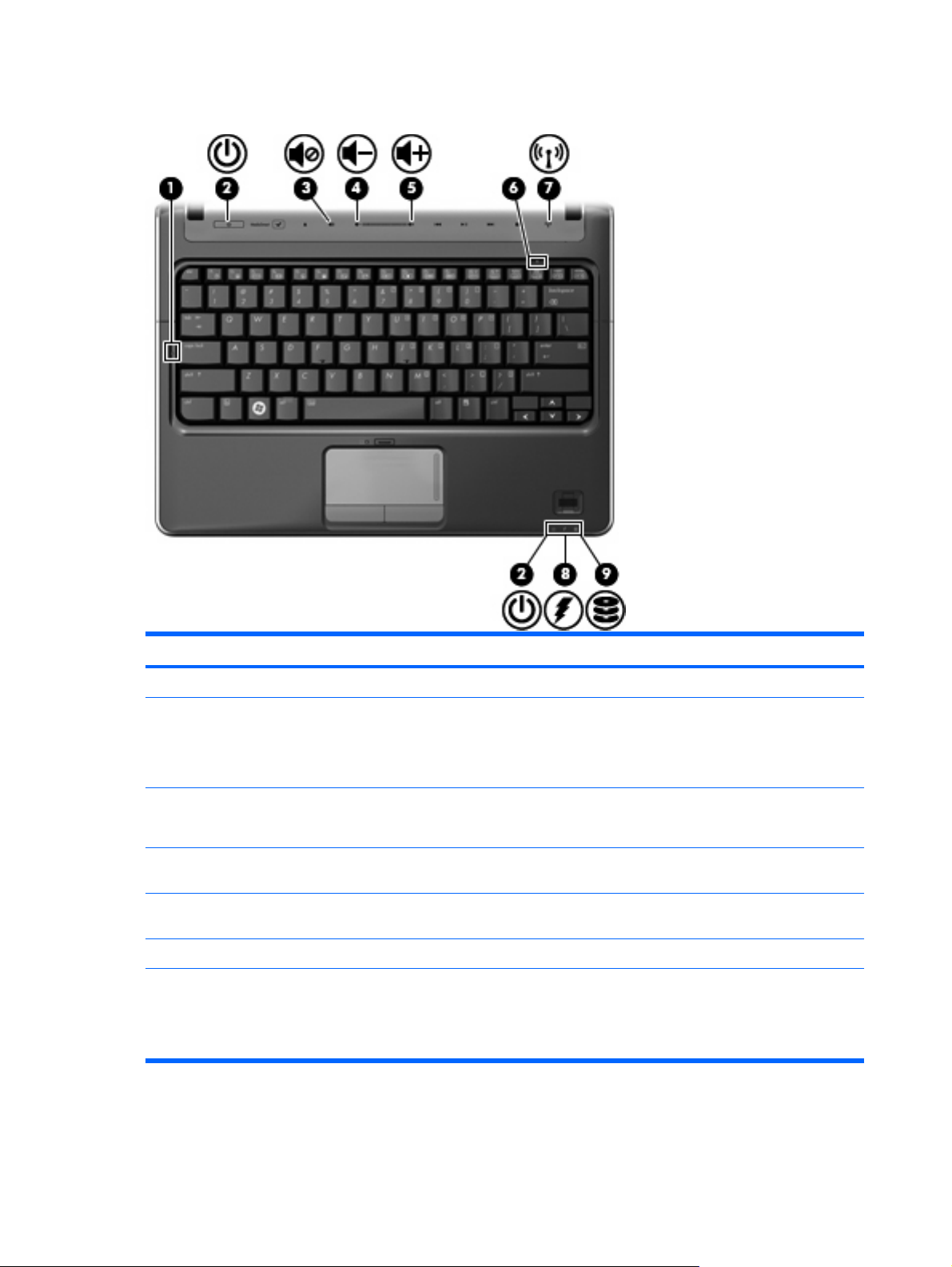
Lights
Component Description
(1) Caps lock light On: Caps lock is on.
(2) Power lights (2)*
(3) Volume mute light
(4) Volume down light On: The volume scroll zone is being used to decrease speaker
(5) Volume up light On: The volume scroll zone is being used to increase speaker
(6) Num lock light On: Num lock is on or the embedded numeric keypad is enabled.
(7) Wireless light
On: The computer is on.
●
Blinking: The computer is in the Sleep state.
●
Off: The computer is off or in Hibernation.
●
White: Computer sound is on.
●
Amber: Computer sound is off.
●
volume.
volume.
On: An integrated wireless device, such as a wireless local
●
area network (WLAN) device and/or a Bluetooth® device, is
on.
Off: All wireless devices are off.
●
8 Chapter 2 External component identification
Page 17
Component Description
(8) Battery light
(9) Drive light Blinking: The hard drive or optical drive is being accessed.
*The 2 power lights display the same information. The light on the power button is visible only when the computer is open. The
power light on the front of the computer is visible whether the computer is open or closed.
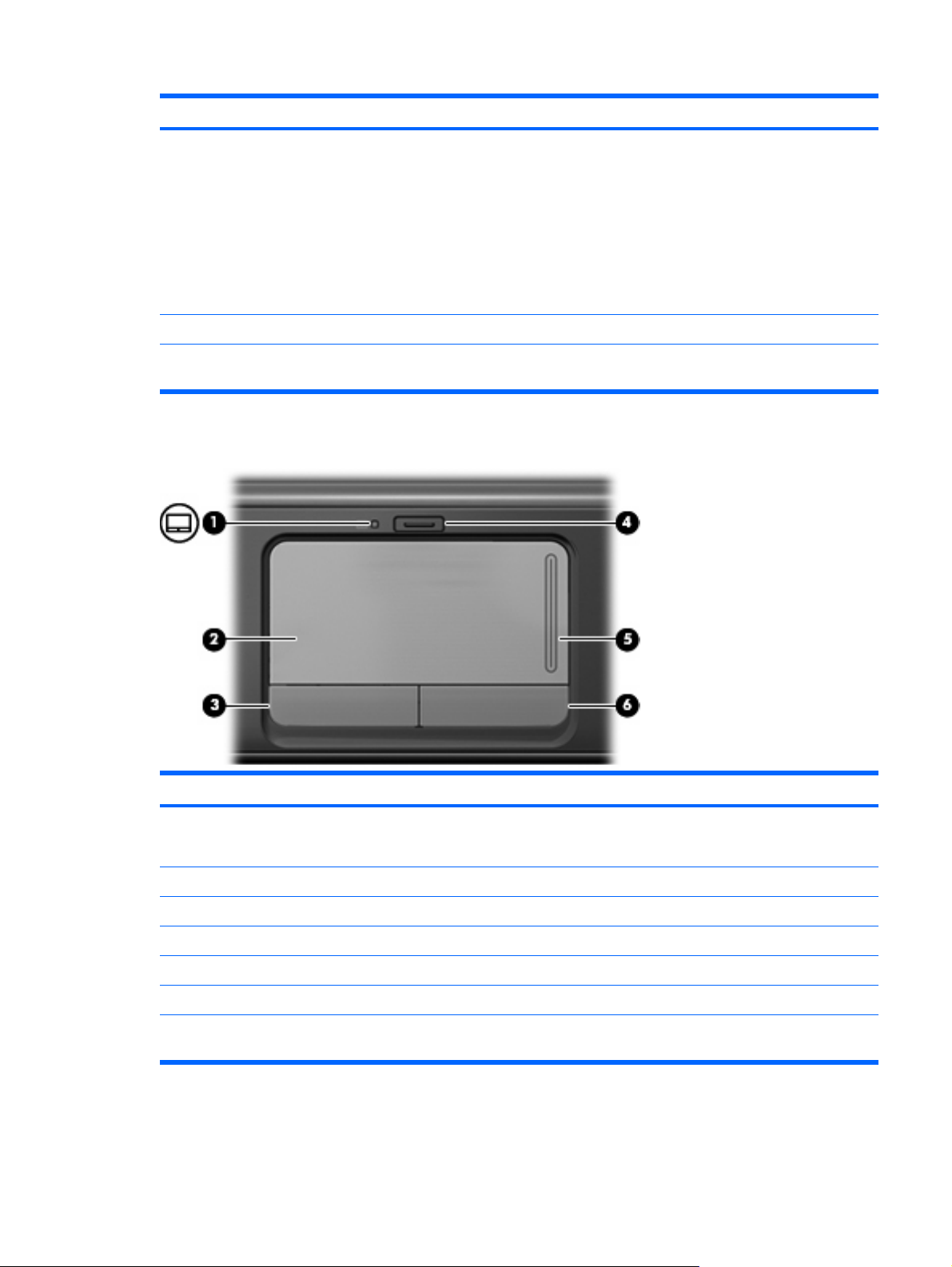
TouchPad
On: A battery is charging.
●
Blinking: A battery that is the only available power source has
●
reached a low battery level. When the battery reaches a
critical battery level, the battery light begins blinking rapidly.
Off: If the computer is plugged into an external power source,
●
the light is turned off when all batteries in the computer are
fully charged. If the computer is not plugged into an external
power source, the light stays off until the battery reaches a
low battery level.
Component Description
(1) TouchPad light
(2) TouchPad* Moves the pointer and selects or activates items on the screen.
(3) Left TouchPad button* Functions like the left button on an external mouse.
(4) TouchPad on/off button Enables/disables the TouchPad.
(5) TouchPad scroll zone Scrolls up or down.
(6) Right TouchPad button* Functions like the right button on an external mouse.
*This table describes factory settings. To view and change pointing device preferences, select Start > Control Panel >
Hardware and Sound > Mouse.
White: TouchPad is enabled.
●
Amber: TouchPad is disabled.
●
Top components 9
Page 18
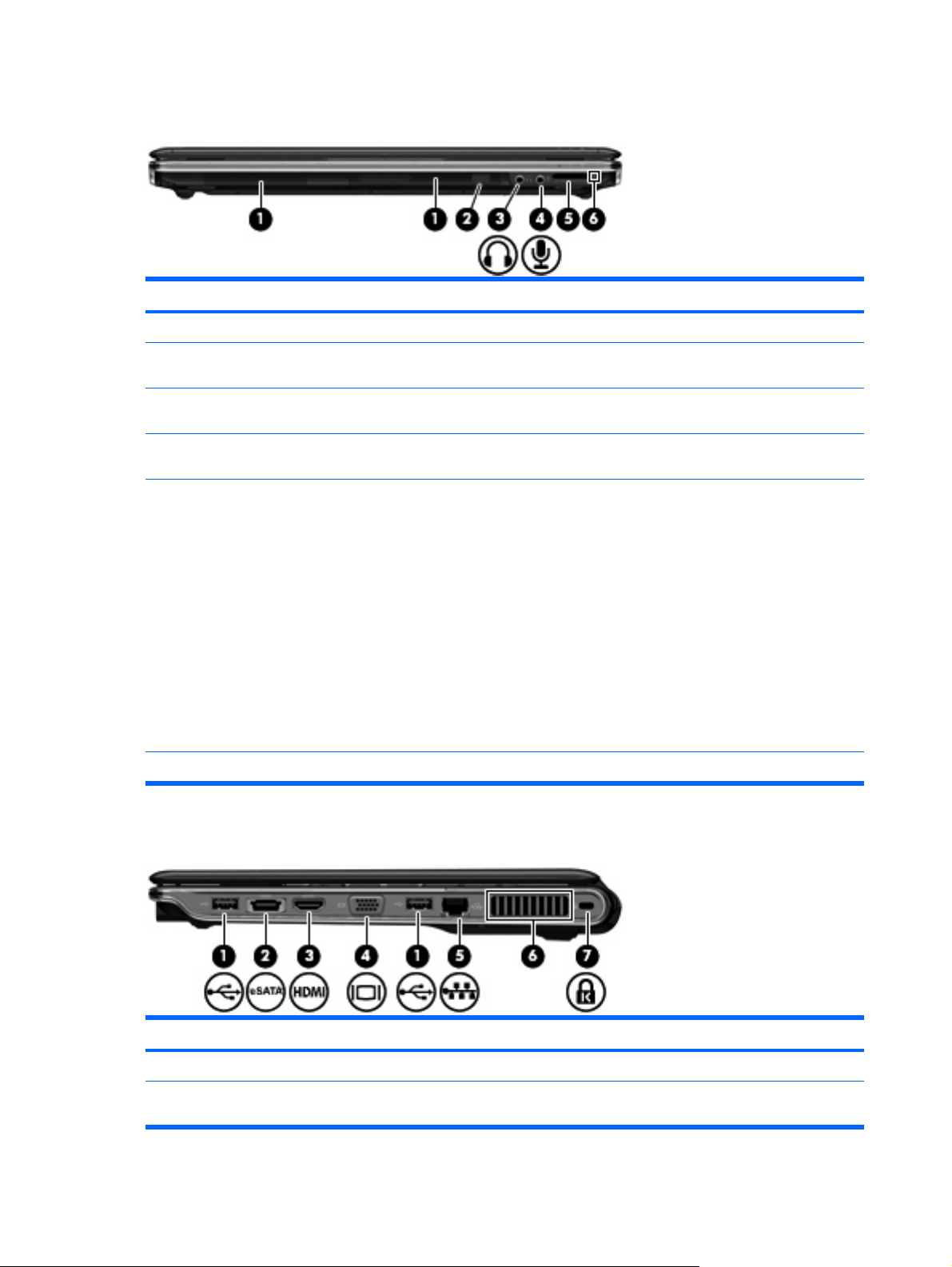
Front components
Component Description
(1) Speakers (2) Produce sound.
(2) Consumer infrared lens Receives a signal from the remote control (provided with select
(3) Audio-out (headphone) jack Produce sound when connected to optional powered stereo
(4) Audio-in (microphone) jack Connects an optional computer headset microphone, stereo array
(5) Digital Media Slot Supports the following digital card formats:
(6) Digital Media Slot light On: The Digital Media Slot is in use.
models only).
speakers, headphones, ear buds, a headset, or television audio.
microphone, or monaural microphone.
Memory Stick (MS)
●
Memory Stick Pro (MSP)
●
MultiMediaCard (MMC)
●
Secure Digital (SD) Memory Card
●
Secure Digital High Capacity (SDHC) Memory Card
●
xD-Picture Card (XD)
●
xD-Picture Card (XD) Type H
●
xD-Picture Card (XD) Type M
●
Right-side components
Component Description
(1) USB ports (2) Connect optional USB devices.
(2) eSATA/USB port Connects a high-performance eSATA component, such as an
10 Chapter 2 External component identification
eSATA external hard drive, or connects an optional USB device.
Page 19
Component Description
(3) HDMI port (select models only) Connects an optional video or audio device, such as a high-
(4) External monitor port Connects an external VGA monitor or projector.
(5) RJ-45 (network) jack Connects a network cable.
(6) Vent Enables airflow to cool internal components.
(7) Security cable slot Attaches an optional security cable to the computer.
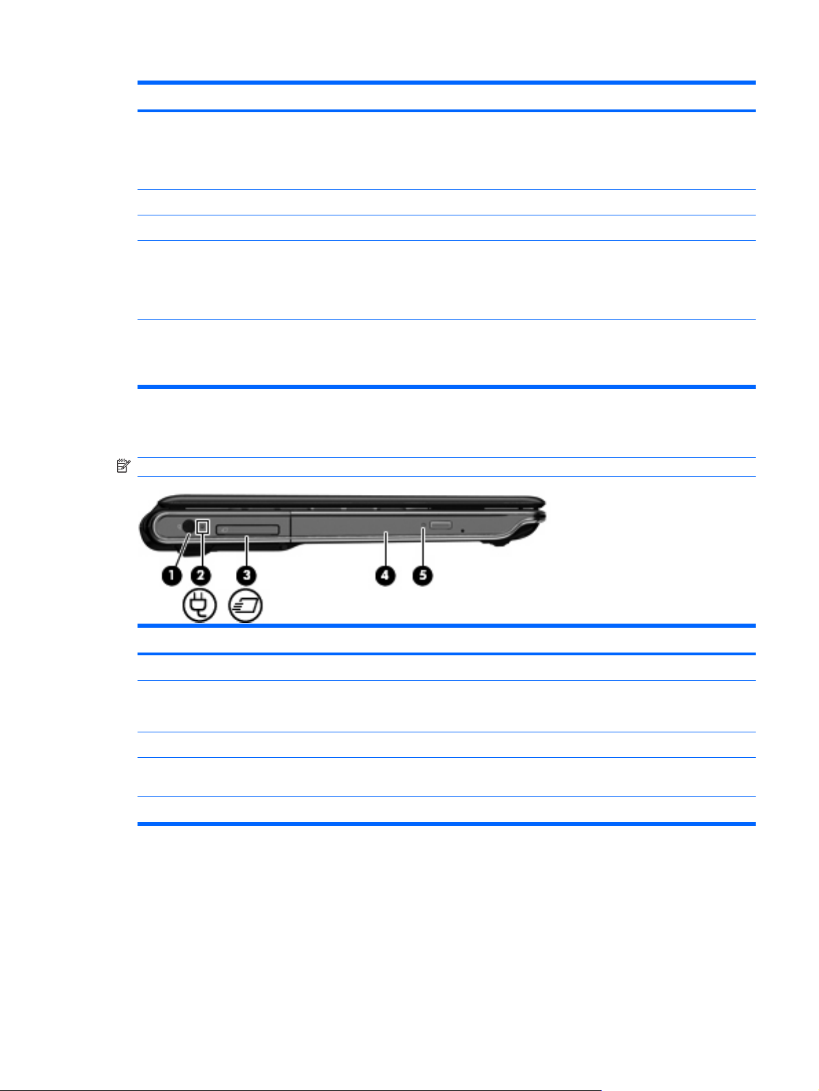
Left-side components
NOTE: Your computer may look slightly different from the illustration in this section.
definition television, or any compatible digital or audio component.
NOTE: Depending on your computer model, the computer may
include an HDMI port or a USB port at this location.
NOTE: The computer fan starts up automatically to cool internal
components and prevent overheating. It is normal for the internal
fan to cycle on and off during routine operation.
NOTE: The security cable is designed to act as a deterrent, but
it may not prevent the computer from being mishandled or stolen.
Component Description
(1) Power connector Connects an AC adapter.
(2) AC adapter light
(3) ExpressCard slot Supports an optional ExpressCard/34 module.
(4) Optical drive Reads optical discs and, on select models, also writes to optical
(5) Optical drive light Blinking: The optical drive is being accessed.
On: The computer is connected to external power.
●
Off: The computer is not connected to external power.
●
discs.
Left-side components 11
Page 20
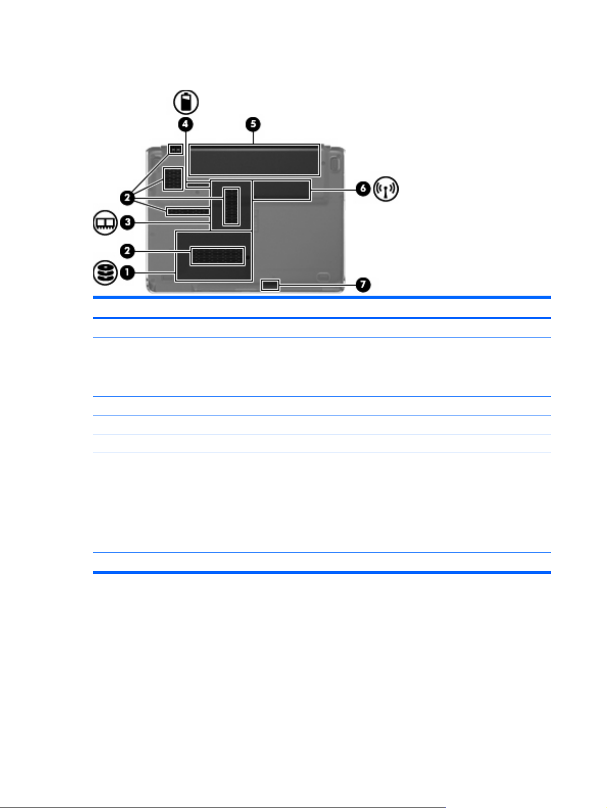
Bottom components
Component Description
(1) Hard drive bay Holds the hard drive.
(2) Vents (5) Enable airflow to cool internal components.
NOTE: The computer fan starts up automatically to cool internal
components and prevent overheating. It is normal for the internal
fan to cycle on and off during routine operation.
(3) Memory module compartment Contains the memory module slots.
(4) Battery release latch Releases the battery from the battery bay.
(5) Battery bay Holds the battery.
(6) Wireless module compartment Holds a wireless LAN module.
NOTE: To prevent an unresponsive system, replace the wireless
module only with a wireless module authorized for use in the
computer by the governmental agency that regulates wireless
devices in your country or region. If you replace the module and
then receive a warning message, remove the module to restore
computer functionality, and then contact technical support through
Help and Support.
(7) Bluetooth compartment Contains a Bluetooth device.
12 Chapter 2 External component identification
Page 21
3 Illustrated parts catalog
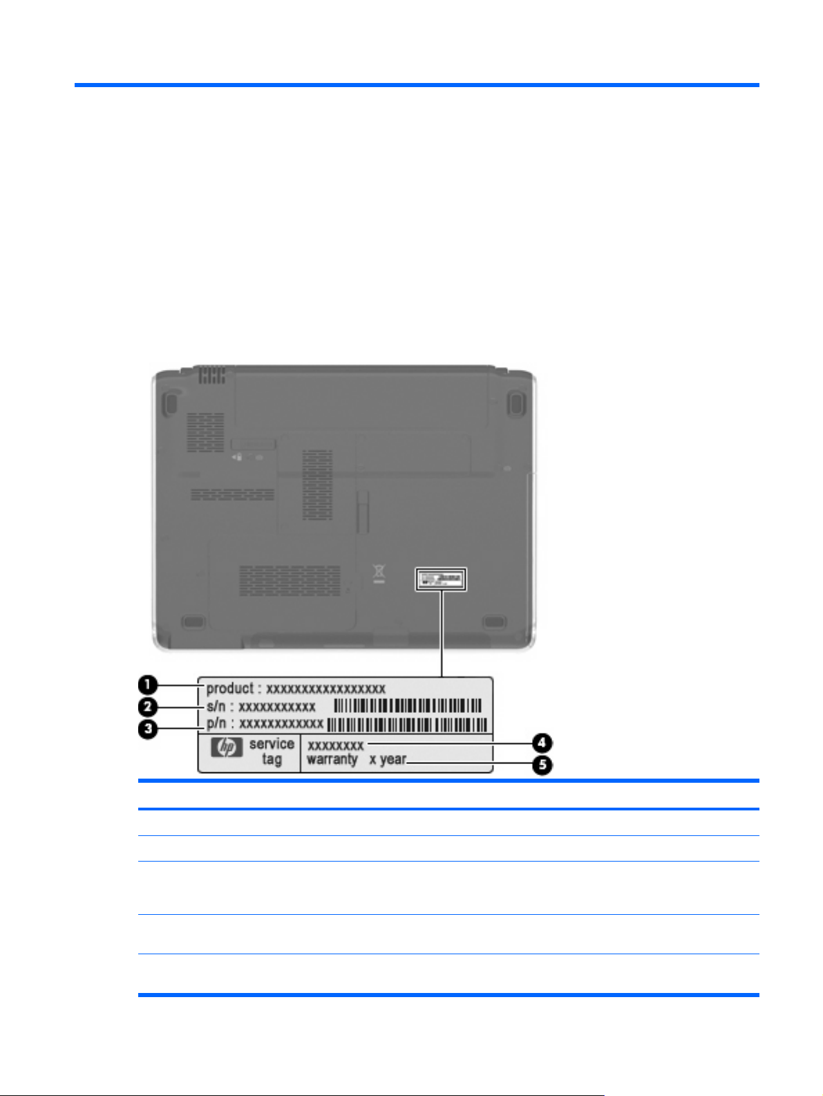
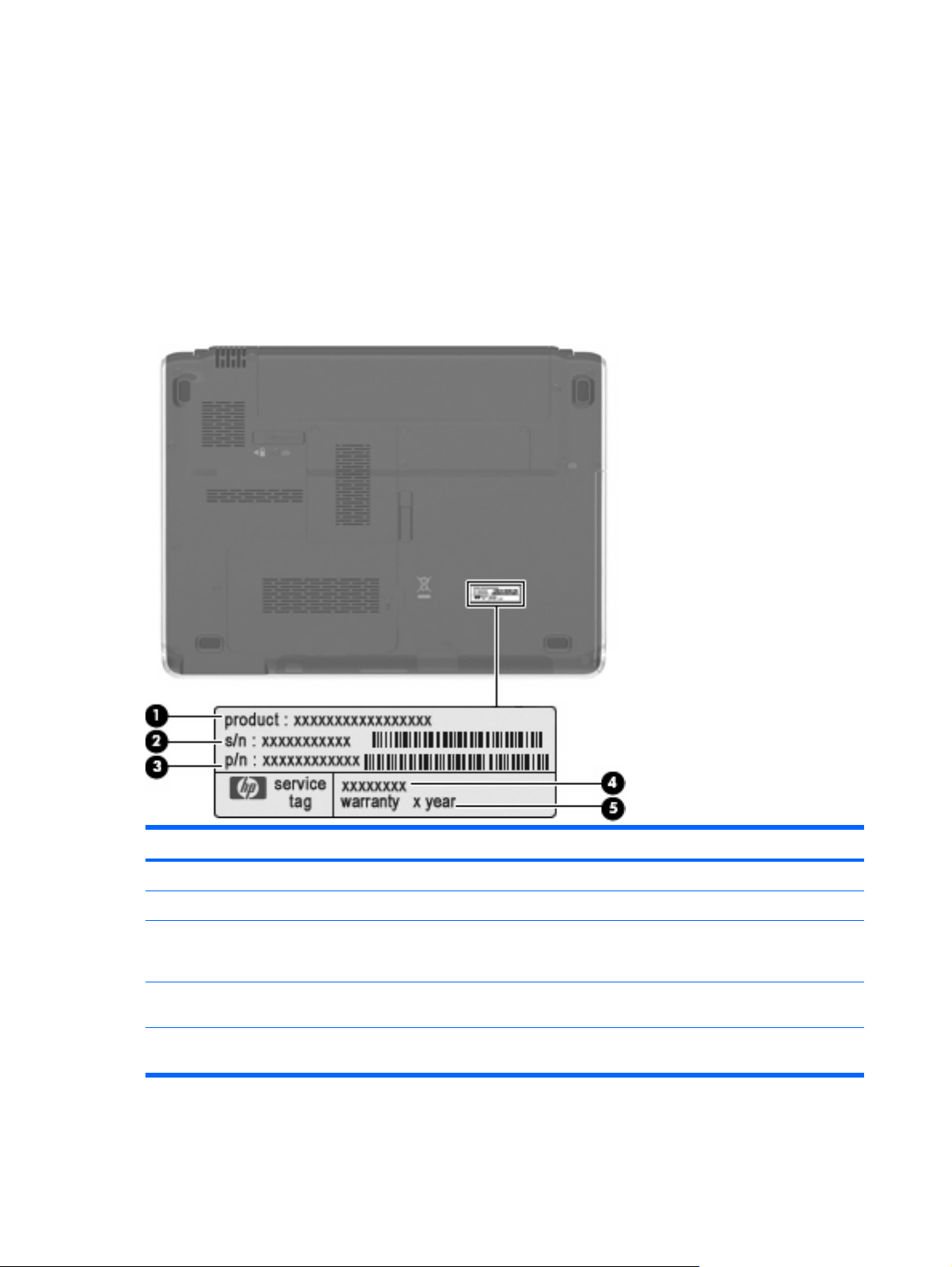
Serial number location
When ordering parts or requesting information, provide the computer serial number and model number
located on the service tag.
Component Description
(1) Product name This is the product name affixed to the front of the computer.
(2) Serial number (s/n) This is an alphanumeric identifier that is unique to each product.
(3) Part number/Product number (p/n) This number provides specific information about the product's
hardware components. The part number helps a service technician
to determine what components and parts are needed.
(4) Model description This is the number used to locate documents, drivers, and support
for the computer.
(5) Warranty period This number describes the duration of the warranty period for the
computer.
Serial number location 13
Page 22

Computer major components
Item Description Spare part number
(1) 13.3-inch, WXGA BrightView display assembly (includes camera/microphone module,
camera/microphone module cable, 2 microphones, and 2 wireless antenna transceivers
and cables)
(2) Switch cover (includes: power button board and cable, LED board and cable) 506240-001
14 Chapter 3 Illustrated parts catalog
506155-001
Page 23

Item Description Spare part number
(3) Keyboard
For use in Canada 507091-121
For use in the United States 507091-001
For use in the United States (with backlight) 507092-001
Plastics Kit (see Plastics Kit on page 19 for more information) 506953-001
(4a) ExpressCard slot bezel
(4b) Wireless module compartment cover
(4c) Hard drive cover
(4d) Memory module compartment cover
(5)
Top cover (includes TouchPad and cable, fingerprint reader board cable, and caps lock
LED board and cable)
(6) Fingerprint reader board (includes fingerprint reader board cable, not illustrated) 506962-001
(7) TouchPad on/off button board 506957-001
(8) TouchPad bracket 507885-001
(9) System board (includes replacement thermal material and power connector cable) 506147-001
(10) LED bracket 507886-001
506241-001
(11) Power connector 507094-001
(12) RTC battery 486835-001
(13) Audio board (includes audio board cable, not illustrated) 507093-001
(14) Processor (includes replacement thermal material)
AMD Turion Ultra Dual-Core ZM-86 2.40-GHz processor (35W, 2-MB L2 cache) 506148-001
AMD Turion Ultra Dual-Core ZM-84 2.30-GHz processor (35W, 2-MB L2 cache) 506149-001
AMD Turion Ultra Dual-Core ZM-82 2.20-GHz processor (35W, 2-MB L2 cache) 506150-001
AMD Turion Dual-Core RM-74 2.20-GHz processor (35W, 1-MB L2 cache) 506151-001
AMD Turion Dual-Core RM-72 2.10-GHz processor (35W, 1-MB L2 cache) 506152-001
AMD Athlon X2 Dual-Core QL-64 2.10-GHz processor (35W, 1-MB L2 cache) 506153-001
AMD Athlon X2 Dual-Core QL-62 2.00-GHz processor (35W, 1-MB L2 cache) 506154-001
(15) Fan and heat sink (includes heat sink retention clip and replacement thermal material) 506960-001
(16) Optical drive (includes bezel and bracket)
DVD±RW and CD-RW SuperMulti Double-Layer Combo Drive (tray-load) 506234-001
DVD±RW and CD-RW SuperMulti Double-Layer Combo Drive (slot-load) 506235-001
(17) Base enclosure (for tray-load optical drive) 506938-001
Base enclosure (for slot-load optical drive) 506239-001
Rubber Foot Kit (not illustrated, includes 4 base enclosure rubber feet) 507887-001
(18) Speakers 506955-001
Computer major components 15
Page 24

Item Description Spare part number
(19) Battery
9-cell, 83-Wh, 2.55-Ah Li-ion 506238-001
6-cell, 55-Wh, 2.55-Ah Li-ion 506237-001
(20) Bluetooth module
NOTE: The Bluetooth module spare part kit does not include a Bluetooth module cable.
The Bluetooth module cable is included in the Cable Kit, spare part number 486847-001.
(21) WLAN module
Broadcom 802.11b/g WLAN module 459263-001
Broadcom 4322AGN 802.11a/b/g/n WLAN module 487330-001
(22) Memory module
4096-MB (PC2-6400, 800-MHz, DDR2) 506934-001
2048-MB (PC2-6400, 800-MHz, DDR2) 506933-001
1024-MB (PC2-6400, 800-MHz, DDR2) 506932-001
(23) Hard drive (includes bracket)
500-GB, 5400-rpm 506232-001
400-GB, 5400-rpm 512225-001
320-GB, 5400-rpm 506231-001
250-GB, 5400-rpm 506230-001
160-GB, 5400-rpm 506229-001
Hard Drive Kit (not illustrated, includes hard drive bracket and screws) 506935-001
398393-002
16 Chapter 3 Illustrated parts catalog
Page 25
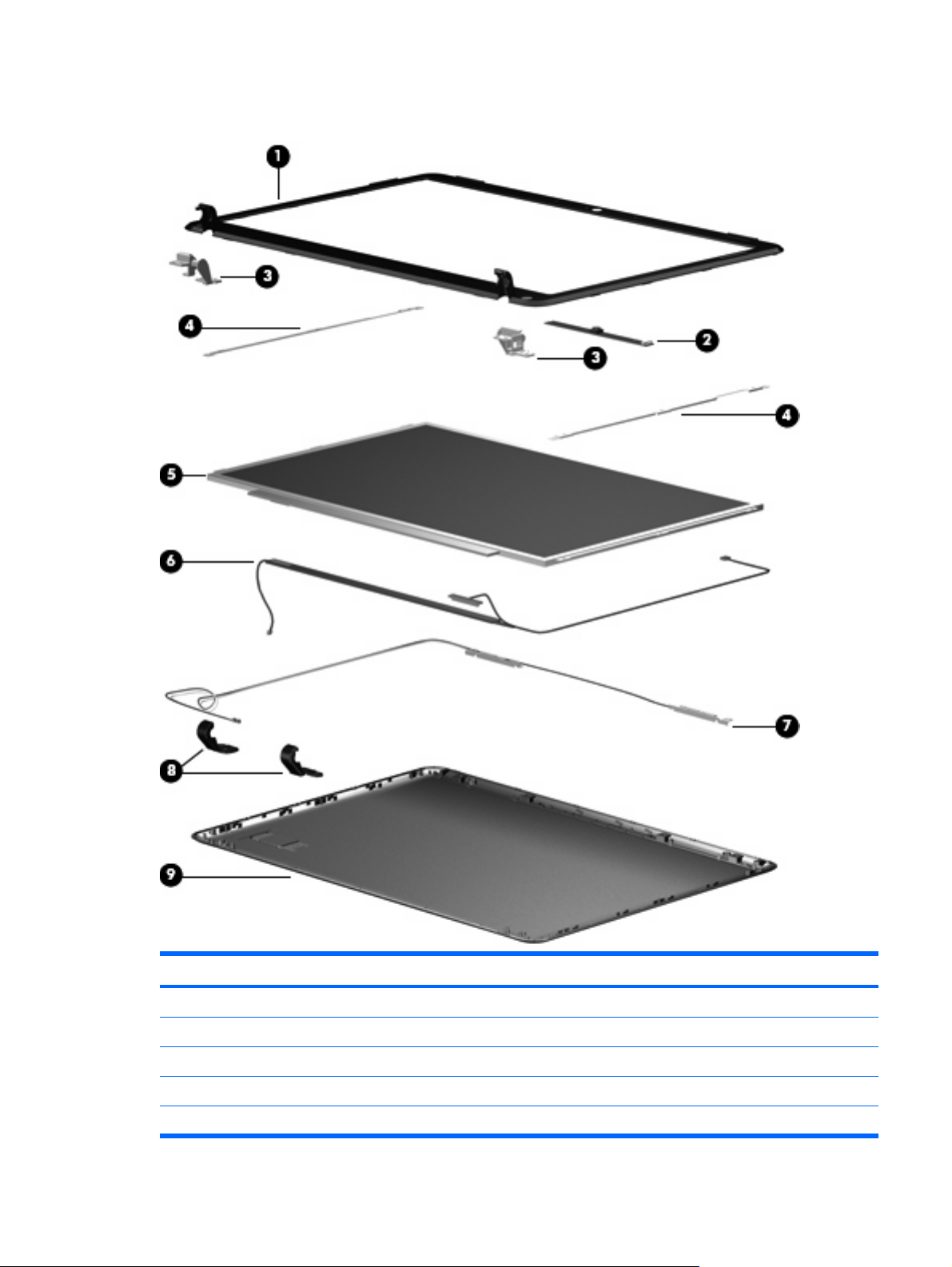
Display assembly components
Item Description Spare part number
(1) Display bezel 506222-001
(2) Camera/microphone module 506930-001
(3) Display Hinge Kit (includes left and right display hinges) 506223-001
(4) Display Bracket Kit 506931-001
(5) 13.3-inch, WXGA BrightView display panel 506156-001
Display assembly components 17
Page 26

Item Description Spare part number
(6) Display Cable Kit (includes 3 wireless antenna transceivers and cables and display panel
cable)
(7) Camera/microphone module cable (included in the Display Cable Kit) 506226-001
(8) Display hinge covers 506224-001
(9) Display enclosure 506225-001
Display Rubber Kit (not illustrated; includes display bezel screw covers and display bezel
bumper pads)
Display Screw Kit (not illustrated) 506228-001
506226-001
506227-001
18 Chapter 3 Illustrated parts catalog
Page 27
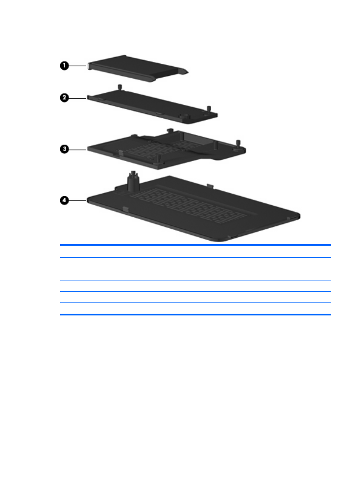
Plastics Kit
Item Description Spare part number
Plastics Kit 506953-001
(1) ExpressCard slot bezel
(2) Wireless module compartment cover
(3) Memory module compartment cover
(4) Hard drive cover (includes 1 captive screw, secured by a C-clip)
Plastics Kit 19
Page 28
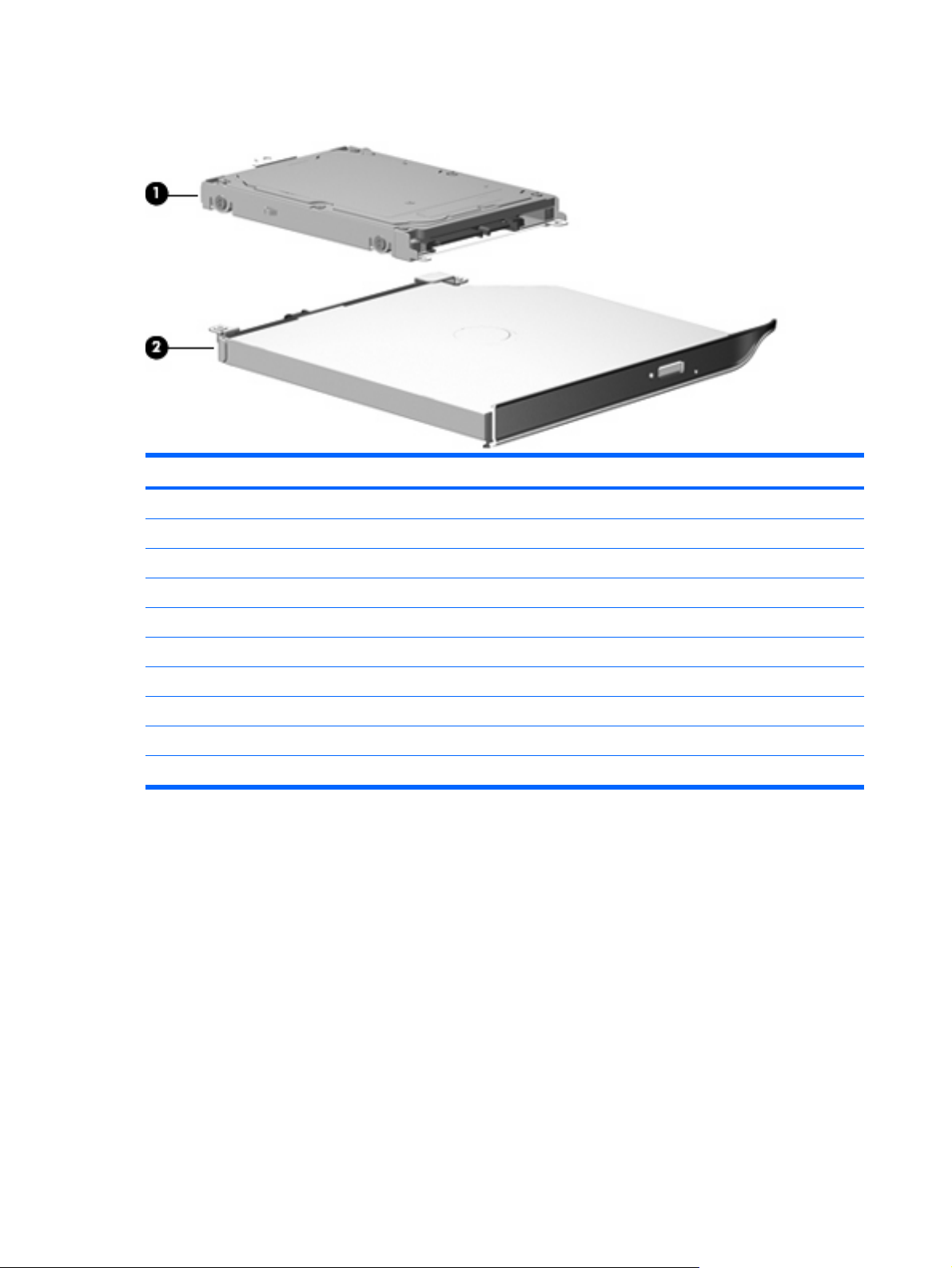
Mass storage devices
Item Description Spare part number
(1) Hard drive (includes bracket)
500-GB, 5400-rpm 506232-001
400-GB, 5400-rpm 512225-001
320-GB, 5400-rpm 506231-001
250-GB, 5400-rpm 506230-001
160-GB, 5400-rpm 506229-001
Hard Drive Kit (not illustrated, includes hard drive bracket and screws) 506935-001
(2) Optical drive (includes bezel and bracket)
DVD±RW and CD-RW SuperMulti Double-Layer Combo Drive (tray-load) 506234-001
DVD±RW and CD-RW SuperMulti Double-Layer Combo Drive (slot-load) 506235-001
20 Chapter 3 Illustrated parts catalog
Page 29

Miscellaneous parts
Description Spare part number
65-W PFC HP Smart Adapter 463958-001
Remote control (fits inside ExpressCard slot) 465539-002
Power cord 490371-001
Screw Kit
Phillips PM2.0×2.0 broadhead screw
●
Phillips PM2.0×3.0 screw
●
Phillips PM2.0×4.0 screw
●
Phillips PM2.0×8.0 captive screw
●
Phillips PM2.5×4.0 screw
●
Phillips PM2.5×5.0 screw
●
Phillips PM2.5×6.0 captive screw
●
Phillips PM2.5×7.0 screw
●
506961-001
Miscellaneous parts 21
Page 30

Sequential part number listing
Spare part
number
398393-002 Bluetooth module (includes double-sided tape)
459263-001 Broadcom 802.11b/g WLAN module
463958–001 65-W PFC HP Smart Adapter
465539-002 Remote control (fits inside ExpressCard slot)
486835-001 RTC battery
486847-001 Cable Kit
487330-001 Broadcom 4322AGN 802.11a/b/g/n WLAN module
490371-001 Power cord for use in the United States
506147-001 System board (includes replacement thermal material and power connector cable)
506148-001 AMD Turion Ultra Dual-Core ZM-86 2.40-GHz processor (35W, 2-MB L2 cache)
506149-001 AMD Turion Ultra Dual-Core ZM-84 2.30-GHz processor (35W, 2-MB L2 cache)
506150-001 AMD Turion Ultra Dual-Core ZM-82 2.20-GHz processor (35W, 2-MB L2 cache)
506151-001 AMD Turion Dual-Core RM-74 2.20-GHz processor (35W, 1-MB L2 cache)
506152-001 AMD Turion Dual-Core RM-72 2.10-GHz processor (35W, 1-MB L2 cache)
506153-001 AMD Athlon X2 Dual-Core QL-64 2.10-GHz processor (35W, 1-MB L2 cache)
Description
506154-001 AMD Athlon X2 Dual-Core QL-62 2.00-GHz processor (35W, 1-MB L2 cache)
506155-001 13.3-inch, WXGA BrightView display assembly (includes camera/microphone module, camera/microphone
506156-001 13.3-inch, WXGA BrightView display panel
506222-001 Display bezel
506223-001 Display Hinge Kit (includes left and right display hinges)
506224-001 Display hinge covers
506225-001 Display enclosure
506226-001 Display Cable Kit (includes 3 wireless antenna transceivers and cables and display panel cable)
506227-001 Display Rubber Kit (includes display bezel screw covers and display bezel bumper pads)
506228-001 Display Screw Kit
506229-001 160-GB, 5400-rpm hard drive (includes bracket)
506230-001 250-GB, 5400-rpm hard drive (includes bracket)
506231-001 320-GB, 5400-rpm hard drive (includes bracket)
506232-001 500-GB, 5400-rpm hard drive (includes bracket)
506234-001 DVD±RW and CD-RW Super Multi Double-Layer Combo Drive (tray-load)
506235-001 DVD±RW and CD-RW Super Multi Double-Layer Combo Drive (slot-load)
module cable, 2 microphones, and 2 wireless antenna transceivers and cables)
22 Chapter 3 Illustrated parts catalog
Page 31

Spare part
number
506237-001 6-cell, 55-Wh, 2.55-Ah Li-ion battery
506238-001 9-cell, 83-Wh, 2.55-Ah Li-ion battery
506239-001 Base enclosure (for slot-loading optical drive)
506240-001 Switch cover (includes LED board and cable)
506241-001 Top cover (includes TouchPad and cable, fingerprint reader board cable, and caps lock LED board and cable)
506930-001 Camera/microphone module
506931-001 Display Bracket Kit
506932-001 1024-MB (PC2-6400, 800-MHz, DDR2) memory module
506933-001 2048-MB (PC2-6400, 800-MHz, DDR2) memory module
506934-001 4096-MB (PC2-6400, 800-MHz, DDR2) memory module
506935-001 Hard Drive Kit (includes hard drive bracket and screws)
506938-001 Base enclosure (for tray-loading optical drive)
506953-001 Plastics Kit
506955-001 Speakers
506957-001 TouchPad on/off button board
Description
506960-001 Fan and heat sink (includes heat sink retention clip and replacement thermal material)
506961-001 Screw Kit
506962-001 Fingerprint reader board (includes fingerprint reader board cable)
507091-001 Keyboard for use in the United States
507091-121 Keyboard for use in Canada
507092-001 Keyboard (with backlight) for use in the United States
507093-001 Audio board (includes audio board cable)
507094-001 Power connector
507885-001 TouchPad bracket
507886-001 LED bracket
507887-001 Rubber Foot Kit (includes 4 base enclosure rubber feet)
512225-001 400-GB, 5400-rpm hard drive (includes bracket)
Sequential part number listing 23
Page 32

4 Removal and replacement procedures
Preliminary replacement requirements
Tools required
You will need the following tools to complete the removal and replacement procedures:
Flat-bladed screwdriver
●
Magnetic screwdriver
●
Phillips P0 and P1 screwdrivers
●
Service considerations
The following sections include some of the considerations that you must keep in mind during
disassembly and assembly procedures.
NOTE: As you remove each subassembly from the computer, place the subassembly (and all
accompanying screws) away from the work area to prevent damage.
Plastic parts
CAUTION: Using excessive force during disassembly and reassembly can damage plastic parts. Use
care when handling the plastic parts. Apply pressure only at the points designated in the maintenance
instructions.
24 Chapter 4 Removal and replacement procedures
Page 33

Cables and connectors
CAUTION: When servicing the computer, be sure that cables are placed in their proper locations
during the reassembly process. Improper cable placement can damage the computer.
Cables must be handled with extreme care to avoid damage. Apply only the tension required to unseat
or seat the cables during removal and insertion. Handle cables by the connector whenever possible. In
all cases, avoid bending, twisting, or tearing cables. Be sure that cables are routed in such a way that
they cannot be caught or snagged by parts being removed or replaced. Handle flex cables with extreme
care; these cables tear easily.
Drive handling
CAUTION: Drives are fragile components that must be handled with care. To prevent damage to the
computer, damage to a drive, or loss of information, observe these precautions:
Before removing or inserting a hard drive, shut down the computer. If you are unsure whether the
computer is off or in Hibernation, turn the computer on, and then shut it down through the operating
system.
Before handling a drive, be sure that you are discharged of static electricity. While handling a drive,
avoid touching the connector.
Before removing a diskette drive or optical drive, be sure that a diskette or disc is not in the drive and
be sure that the optical drive tray is closed.
Handle drives on surfaces covered with at least one inch of shock-proof foam.
Avoid dropping drives from any height onto any surface.
After removing a hard drive, an optical drive, or a diskette drive, place it in a static-proof bag.
Avoid exposing a hard drive to products that have magnetic fields, such as monitors or speakers.
Avoid exposing a drive to temperature extremes or liquids.
If a drive must be mailed, place the drive in a bubble pack mailer or other suitable form of protective
packaging and label the package “FRAGILE.”
Preliminary replacement requirements 25
Page 34

Grounding guidelines
Electrostatic discharge damage
Electronic components are sensitive to electrostatic discharge (ESD). Circuitry design and structure
determine the degree of sensitivity. Networks built into many integrated circuits provide some protection,
but in many cases, ESD contains enough power to alter device parameters or melt silicon junctions.
A discharge of static electricity from a finger or other conductor can destroy static-sensitive devices or
microcircuitry. Even if the spark is neither felt nor heard, damage may have occurred.
An electronic device exposed to ESD may not be affected at all and can work perfectly throughout a
normal cycle. Or the device may function normally for a while, then degrade in the internal layers,
reducing its life expectancy.
CAUTION: To prevent damage to the computer when you are removing or installing internal
components, observe these precautions:
Keep components in their electrostatic-safe containers until you area ready to install them.
Use nonmagnetic tools.
Before touching an electronic component, discharge static electricity by using the guidelines described
in this section.
Avoid touching pins, leads, and circuitry. Handle electronic components as little as possible.
If you remove a component, place it in an electrostatic-safe container.
The following table shows how humidity affects the electrostatic voltage levels generated by different
activities.
CAUTION: A product can be degraded by as little as 700 V.
Typical electrostatic voltage levels
Relative humidity
Event 10% 40% 55%
Walking across carpet 35,000 V 15,000 V 7,500 V
Walking across vinyl floor 12,000 V 5,000 V 3,000 V
Motions of bench worker 6,000 V 800 V 400 V
Removing DIPS from plastic tube 2,000 V 700 V 400 V
Removing DIPS from vinyl tray 11,500 V 4,000 V 2,000 V
Removing DIPS from Styrofoam 14,500 V 5,000 V 3,500 V
Removing bubble pack from PCB 26,500 V 20,000 V 7,000 V
Packing PCBs in foam-lined box 21,000 V 11,000 V 5,000 V
26 Chapter 4 Removal and replacement procedures
Page 35

Packaging and transporting guidelines
Follow these grounding guidelines when packaging and transporting equipment:
To avoid hand contact, transport products in static-safe tubes, bags, or boxes.
●
Protect ESD-sensitive parts and assemblies with conductive or approved containers or packaging.
●
Keep ESD-sensitive parts in their containers until the parts arrive at static-free workstations.
●
Place items on a grounded surface before removing items from their containers.
●
Always be properly grounded when touching a component or assembly.
●
Store reusable ESD-sensitive parts from assemblies in protective packaging or nonconductive
●
foam.
Use transporters and conveyors made of antistatic belts and roller bushings. Be sure that
●
mechanized equipment used for moving materials is wired to ground and that proper materials are
selected to avoid static charging. When grounding is not possible, use an ionizer to dissipate
electric charges.
Workstation guidelines
Follow these grounding workstation guidelines:
Cover the workstation with approved static-shielding material.
●
Use a wrist strap connected to a properly grounded work surface and use properly grounded tools
●
and equipment.
Use conductive field service tools, such as cutters, screwdrivers, and vacuums.
●
When fixtures must directly contact dissipative surfaces, use fixtures made only of static-safe
●
materials.
Keep the work area free of nonconductive materials, such as ordinary plastic assembly aids and
●
Styrofoam.
Handle ESD-sensitive components, parts, and assemblies by the case or PCM laminate. Handle
●
these items only at static-free workstations.
Avoid contact with pins, leads, or circuitry.
●
Turn off power and input signals before inserting or removing connectors or test equipment.
●
Preliminary replacement requirements 27
Page 36

Equipment guidelines
Grounding equipment must include either a wrist strap or a foot strap at a grounded workstation.
When seated, wear a wrist strap connected to a grounded system. Wrist straps are flexible straps
●
with a minimum of one megohm ±10% resistance in the ground cords. To provide proper ground,
wear a strap snugly against the skin at all times. On grounded mats with banana-plug connectors,
use alligator clips to connect a wrist strap.
When standing, use foot straps and a grounded floor mat. Foot straps (heel, toe, or boot straps)
●
can be used at standing workstations and are compatible with most types of shoes or boots. On
conductive floors or dissipative floor mats, use foot straps on both feet with a minimum of one
megohm resistance between the operator and ground. To be effective, the conductive strips must
be worn in contact with the skin.
The following grounding equipment is recommended to prevent electrostatic damage:
Antistatic tape
●
Antistatic smocks, aprons, and sleeve protectors
●
Conductive bins and other assembly or soldering aids
●
Nonconductive foam
●
Conductive tabletop workstations with ground cords of one megohm resistance
●
Static-dissipative tables or floor mats with hard ties to the ground
●
Field service kits
●
Static awareness labels
●
Material-handling packages
●
Nonconductive plastic bags, tubes, or boxes
●
Metal tote boxes
●
Electrostatic voltage levels and protective materials
●
The following table lists the shielding protection provided by antistatic bags and floor mats.
Material Use Voltage protection level
Antistatic plastic Bags 1,500 V
Carbon-loaded plastic Floor mats 7,500 V
Metallized laminate Floor mats 5,000 V
28 Chapter 4 Removal and replacement procedures
Page 37

Unknown user password
If the computer you are servicing has an unknown user password, follow these steps to clear the
password.
NOTE: These steps also clear CMOS.
Before disassembling the computer, follow these steps:
1. Shut down the computer. If you are unsure whether the computer is off or in Hibernation, turn the
computer on, and then shut it down through the operating system.
2. Disconnect all external devices connected to the computer.
3. Disconnect the power from the computer by first unplugging the power cord from the AC outlet and
then unplugging the AC adapter from the computer.
4. Remove the battery (see
5. Remove the RTC battery (see
6. Wait approximately 5 minutes.
7. Replace the RTC battery and reassemble the computer.
8. Connect AC power to the computer. Do not reinsert any batteries at this time.
9. Turn on the computer.
All passwords and all CMOS settings have been cleared.
Battery on page 32).
RTC battery on page 57).
Preliminary replacement requirements 29
Page 38
Component replacement procedures
This chapter provides removal and replacement procedures.
There are as many as 69 screws, in 8 different sizes, that must be removed, replaced, or loosened when
servicing the computer. Make special note of each screw size and location during removal and
replacement.
Serial number
When ordering parts or requesting information, provide the computer serial number and model
description provided on the service tag.
Component Description
(1) Product name This is the product name affixed to the front of the computer.
(2) Serial number (s/n) This is an alphanumeric identifier that is unique to each product.
(3) Part number/Product number (p/n) This number provides specific information about the product's
(4) Model description This is the number used to locate documents, drivers, and support
(5) Warranty period This number describes the duration of the warranty period for the
30 Chapter 4 Removal and replacement procedures
hardware components. The part number helps a service technician
to determine what components and parts are needed.
for the computer.
computer.
Page 39

Computer feet
Description Spare part number
Rubber Foot Kit (includes 4 base enclosure rubber feet) 507887-001
The computer feet are adhesive-backed rubber pads. The feet attach to the base enclosure in the
locations illustrated below.
Component replacement procedures 31
Page 40

Battery
Description Spare part number
9-cell, 83-Wh, 2.55-Ah Li-ion 506236-001
6-cell, 55-Wh, 2.55-Ah Li-ion 506237-001
Before disassembling the computer, follow these steps
1. Shut down the computer. If you are unsure whether the computer is off or in Hibernation, turn the
computer on, and then shut it down through the operating system.
2. Disconnect all external devices connected to the computer.
3. Disconnect the power from the computer by first unplugging the power cord from the AC outlet and
then unplugging the AC adapter from the computer.
Remove the battery:
1. Turn the computer upside down on a flat surface with the battery bay toward you.
2. Slide and release the battery release latch (1).
NOTE: The battery release latch automatically returns to its original position.
3. Lift the battery by the inner edge (2) to release the battery from the battery bay.
4. Remove the battery (3).
To install the battery, insert the outer edge of the battery into the battery bay, and then press down on
the inner edge until the battery is seated. The battery release latch automatically locks the battery in
place.
32 Chapter 4 Removal and replacement procedures
Page 41

WLAN module
Description Spare part number
Broadcom 802.11b/g WLAN module 459263-001
Broadcom 4322AGN 802.11a/b/g/n WLAN module 487330-001
Before removing the WLAN module, follow these steps:
1. Shut down the computer. If you are unsure whether the computer is off or in Hibernation, turn the
computer on, and then shut it down through the operating system.
2. Disconnect all external devices connected to the computer.
3. Disconnect the power from the computer by first unplugging the power cord from the AC outlet and
then unplugging the AC adapter from the computer.
4. Remove the battery (see
Battery on page 32).
Remove the WLAN module:
NOTE: To prevent an unresponsive system, replace the wireless module only with a wireless module
authorized for use in the computer by the governmental agency that regulates wireless devices in your
country or region. If you replace the module and then receive a warning message, remove the module
to restore computer functionality, and then contact technical support through Help and Support.
1. Loosen the Phillips PM2.5×6.0 screws (1) that secure the wireless module compartment cover to
the computer.
2. Lift the rear edge of the cover (2), swing it up, and remove the cover (3). The wireless module
compartment cover is included in the Plastics Kit, spare part number 506953-001.
3. Disconnect the two WLAN antenna cables (1) from the WLAN module.
NOTE: The black WLAN antenna cable is connected to the WLAN module “Main” terminal. The
white WLAN antenna cable is connected to the WLAN module “Aux” terminal.
NOTE: Computer models equipped with an 802.11ab/g/n WLAN module will have an additional
wireless antenna cable, yellow in color.
Component replacement procedures 33
Page 42
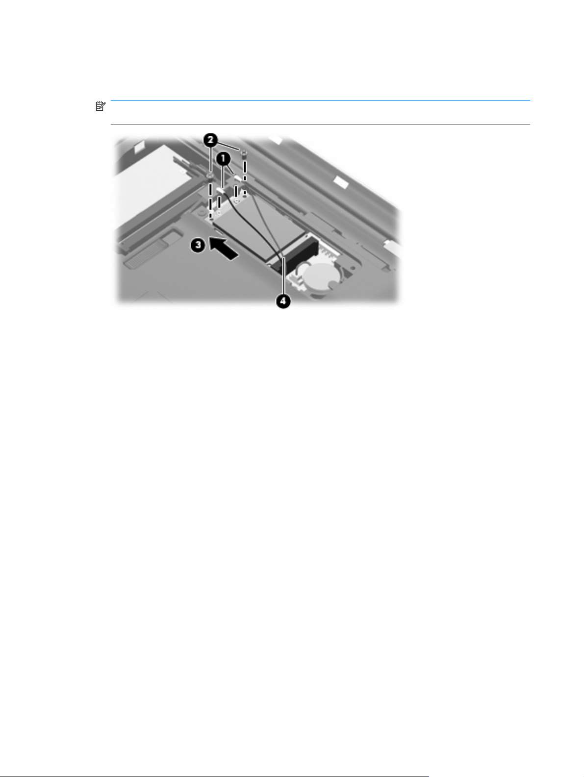
4. Remove the two Phillips PM2.0×4.0 screws (2) that secure the WLAN module to the computer.
5. Remove the WLAN module (3) by pulling it away from the slot at an angle.
NOTE: WLAN modules are designed with a notch (4) to prevent incorrect insertion into the WLAN
module slot.
Reverse this procedure to install a WLAN module.
34 Chapter 4 Removal and replacement procedures
Page 43

Optical drive
NOTE: The optical drive spare part kit includes an optical drive bezel.
Description Spare part number
DVD±RW and CD-RW SuperMulti Double-Layer Combo Drive (tray-load) 506234-001
DVD±RW and CD-RW SuperMulti Double-Layer Combo Drive (slot-load) 506235-001
Before removing the optical drive, follow these steps:
1. Shut down the computer. If you are unsure whether the computer is off or in Hibernation, turn the
computer on, and then shut it down through the operating system.
2. Disconnect all external devices connected to the computer.
3. Disconnect the power from the computer by first unplugging the power cord from the AC outlet and
then unplugging the AC adapter from the computer.
4. Remove the battery (see
Battery on page 32).
Remove the optical drive:
1. Slide the optical drive release latch (1) to release the optical drive from the computer.
2. Remove the optical drive (2) by sliding it out of the optical drive bay.
To install the optical drive, insert the rear edge of the optical drive into the optical drive bay and slide it
in until the optical drive is seated. The optical drive release latch automatically locks the optical drive in
place.
Component replacement procedures 35
Page 44

Memory module
Description Spare part number
4096-MB (PC2-6400, 800-MHz, DDR2) 506934-001
2048-MB (PC2-6400, 800-MHz, DDR2) 506933-001
1024-MB (PC2-6400, 800-MHz, DDR2) 506932-001
Before removing the memory module, follow these steps:
1. Shut down the computer. If you are unsure whether the computer is off or in Hibernation, turn the
computer on, and then shut it down through the operating system.
2. Disconnect all external devices connected to the computer.
3. Disconnect the power from the computer by first unplugging the power cord from the AC outlet and
then unplugging the AC adapter from the computer.
4. Remove the battery (see
Battery on page 32).
Remove the memory module:
1. Loosen the two Phillips PM2.5×6.0 captive screws (1) that secure the memory module
compartment cover to the computer.
2. Lift the rear edge (2) of the cover, swing it up and forward, and remove the cover (3). The memory
module compartment cover is included in the Plastics Kit, spare part number 506953-001.
3. Spread the retaining tabs (1) on each side of the memory module slot to release the memory
module. (The edge of the module opposite the slot rises away from the computer.)
36 Chapter 4 Removal and replacement procedures
Page 45
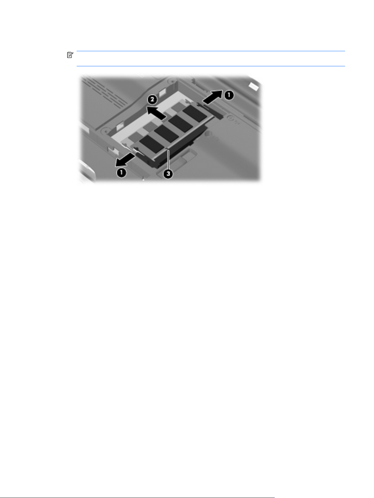
4. Remove the module (2) by pulling it away from the slot at an angle.
NOTE: Memory modules are designed with a notch (3) to prevent incorrect insertion into the
memory module slot.
Reverse this procedure to install a memory module.
Component replacement procedures 37
Page 46
Hard drive
NOTE: The hard drive spare part kit includes a hard drive bracket.
Description Spare part number
500-GB, 5400-rpm 506232-001
400-GB, 5400-rpm 512225-001
320-GB, 5400-rpm 506231-001
250-GB, 5400-rpm 506230-001
160-GB, 5400-rpm 506229-001
Hard Drive Kit (includes hard drive bracket and screws) 506935-001
Before removing the hard drive, follow these steps:
1. Shut down the computer. If you are unsure whether the computer is off or in Hibernation, turn the
2. Disconnect all external devices connected to the computer.
3. Disconnect the power from the computer by first unplugging the power cord from the AC outlet and
computer on, and then shut it down through the operating system.
then unplugging the AC adapter from the computer.
4. Remove the battery (see
Battery on page 32).
Remove the hard drive:
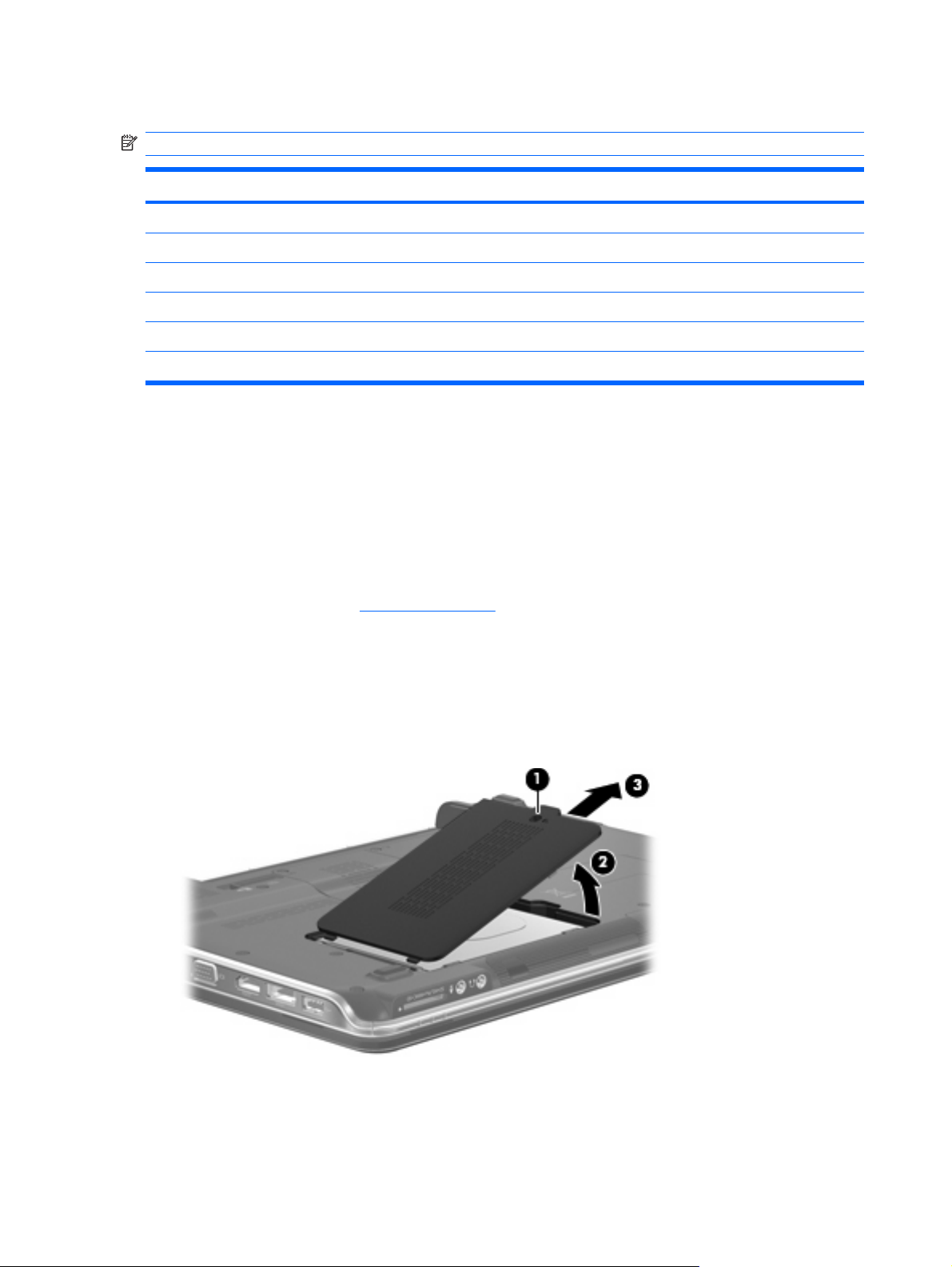
1. Loosen the Phillips PM2.5×6.0 captive screw (1) that secures the hard drive cover to the
computer.
2. Lift the right side of the hard drive cover (2), and remove the cover (3). The hard drive cover is
included in the Plastics Kit, spare part number 506953-001.
3. Loosen the two Phillips PM2.5×4.0 screws (1) that secure the hard drive to the computer.
4. Grasp the Mylar tab (2), and pull the hard drive to the right until it disconnects from the system
board.
38 Chapter 4 Removal and replacement procedures
Page 47
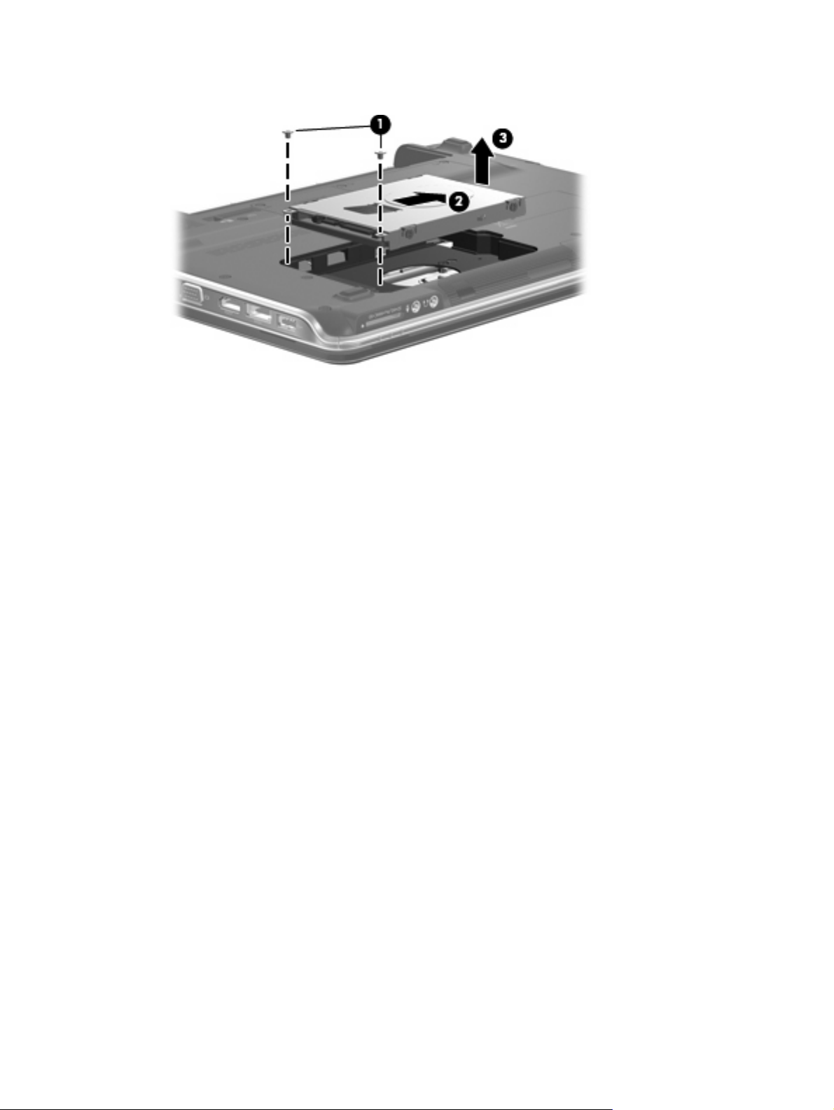
5. Remove the hard drive (3) from the hard drive bay.
Reverse this procedure to reassemble and install the hard drive.
Component replacement procedures 39
Page 48

Keyboard and switch cover
NOTE: The keyboard and switch cover must be removed simultaneously.
Description Spare part number Description Spare part number
Keyboard (The United States) 507091-001 Backlit keyboard (The United
States)
Keyboard (Canada) 507091-121 Switch cover 506240-001
507092-001
Before removing the keyboard and switch cover, follow these steps:
1. Shut down the computer. If you are unsure whether the computer is off or in Hibernation, turn the
computer on, and then shut it down through the operating system.
2. Disconnect all external devices connected to the computer.
3. Disconnect the power from the computer by first unplugging the power cord from the AC outlet and
then unplugging the AC adapter from the computer.
4. Remove the battery (see
5. Remove the hard drive (see
Battery on page 32).
Hard drive on page 38).
Remove the keyboard and switch cover:
1. Remove the three Phillips PM2.5×7.0 screws (1) that secure the keyboard to the computer.
2. Remove the nine Phillips screws (2) that secure the switch cover to the computer.
3. Turn the computer right-side up, with the front toward you.
4. Open the computer as far as possible.
40 Chapter 4 Removal and replacement procedures
Page 49

5. Lift the rear edge of the switch cover (1) up slightly and pull back at an angle (2) to access the
keyboard.
6. Lift the rear edge of the keyboard (1) and swing it up and forward until it rests upside down on the
palm rest (2).
Component replacement procedures 41
Page 50
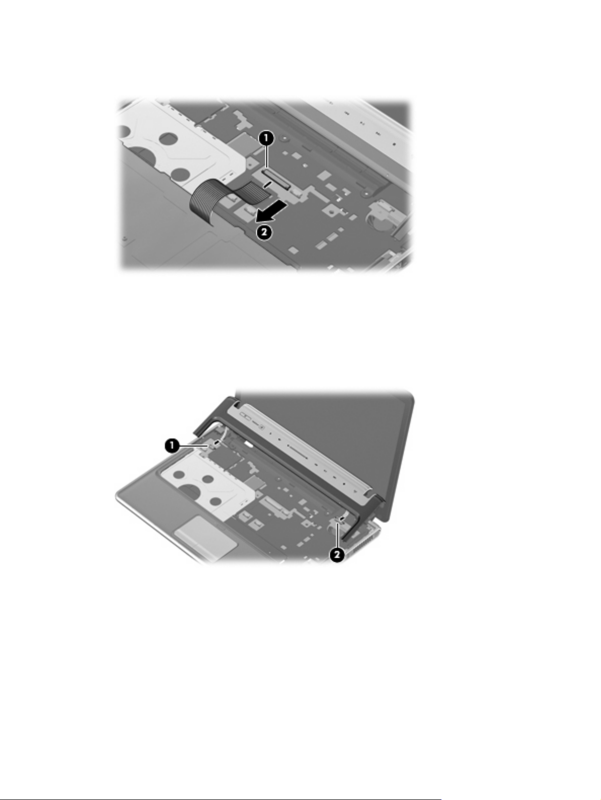
7. Release the zero insertion force (ZIF) connector to which the keyboard cable (1) is attached and
disconnect the cable (2) from the system board.
8. Remove the keyboard.
9. Disconnect the power button board cable (1) from the system board.
10. Release the ZIF connector to which the LED board cable is connected, and disconnect the
cable (2) from the system board.
11. Remove the switch cover.
Reverse this procedure to install the keyboard and switch cover.
42 Chapter 4 Removal and replacement procedures
Page 51

Display assembly
Description Spare part number
13.3-inch, WXGA BrightView display assembly (includes camera/microphone module, camera/
microphone module cable, 2 microphones, and 3 wireless antenna transceivers and cables)
506155-001
Before removing the display assembly, follow these steps:
1. Shut down the computer. If you are unsure whether the computer is off or in Hibernation, turn the
computer on, and then shut it down through the operating system.
2. Disconnect all external devices connected to the computer.
3. Disconnect the power from the computer by first unplugging the power cord from the AC outlet and
then unplugging the AC adapter from the computer.
4. Remove the battery (see
5. Disconnect the wireless antenna cables from the WLAN module (see
6. Remove the keyboard and switch cover (see
Battery on page 32).
WLAN module on page 33).
Keyboard and switch cover on page 40).
Remove the display assembly:
1. Close the computer.
2. Turn the computer upside down.
3. Pull the WLAN antenna cables (1) down through the channel (2) located between the base
enclosure (3) and the top cover on the opposite side.
4. Turn the computer right-side up.
5. Open the computer as far as possible.
6. Remove the WLAN antenna cables (1) from the clips and routing channel built into the top cover.
Component replacement procedures 43
Page 52
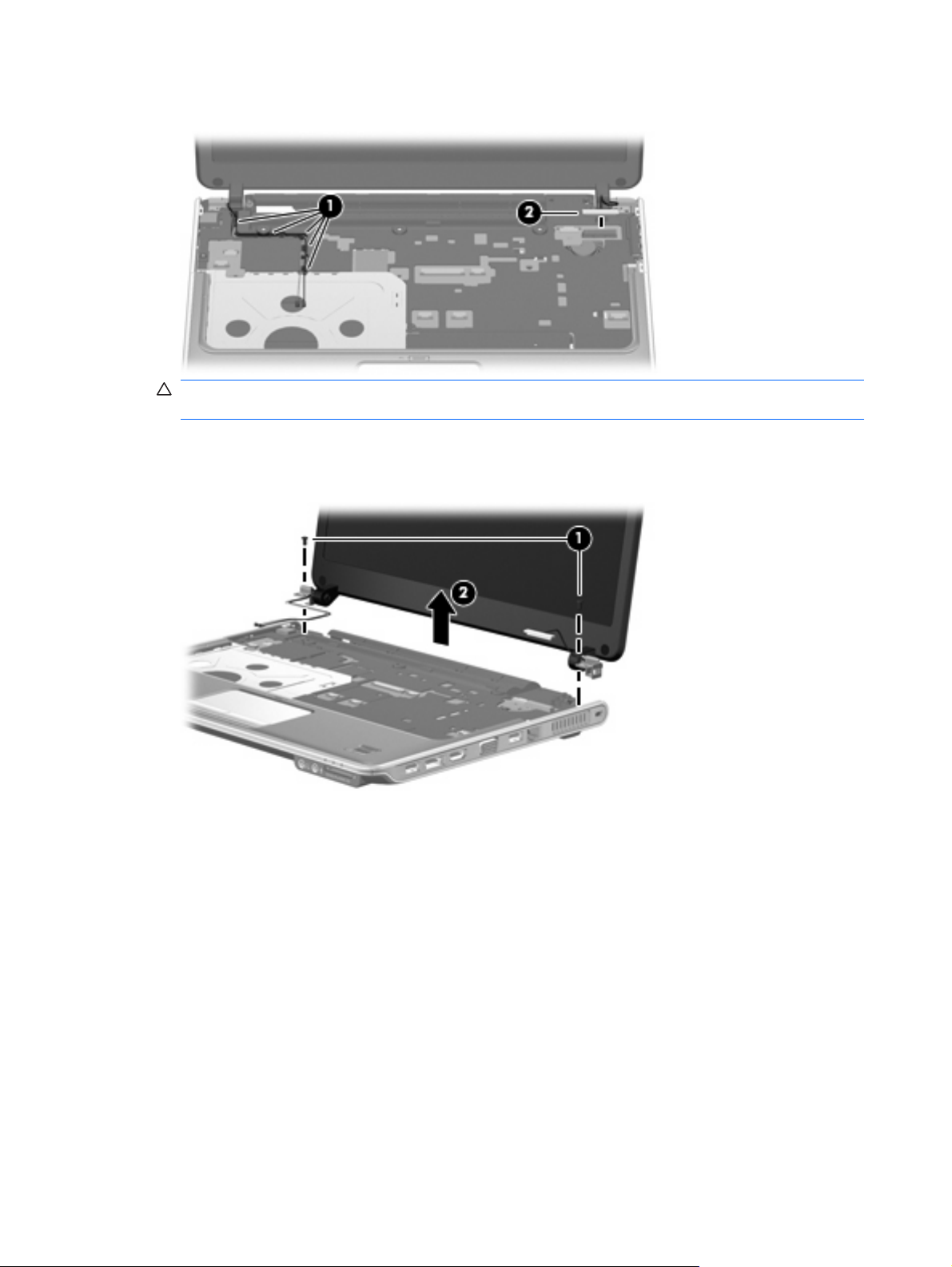
7. Disconnect the display panel cable (2) from the system board.
CAUTION: The display assembly will be unsupported when the following screws are removed.
To prevent damage to the display assembly, support it before removing the screws.
8. Remove the two Phillips PM2.5×6.0 screws (1) that secure the display assembly to the computer.
9. Remove the display assembly (2).
10. If it is necessary to replace any of the display assembly internal components, remove the two rubber
screw covers (1) on the display bezel bottom edge. The rubber screw covers are included in the
Display Rubber Kit, spare part number 506227-001.
44 Chapter 4 Removal and replacement procedures
Page 53

11. Remove the two Phillips PM2.5×5.0 screws (2) that secure the display bezel to the display
assembly.
12. Flex the inside edges of the left and right sides (1) and the top and bottom edges (2) of the display
bezel until the bezel disengages from the display enclosure.
13. Remove the display bezel (3). The display bezel is available using spare part number
506222-001.
14. If it is necessary to replace the camera/microphone module, release the module (1) as far as the
camera/microphone module cable allows.
Component replacement procedures 45
Page 54

15. Disconnect the camera/microphone module cable from the module (2), and remove the camera/
microphone module. The camera/microphone module is available using spare part number
506930-001.
16. If it is necessary to replace the display panel, remove the four Phillips PM2.5×4.0 screws (1) that
secure the panel to the display enclosure.
17. Remove the left and right display panel brackets (2).
18. Disconnect the display logo LED board cable (3) from the display panel cable.
19. Remove the display panel (4) from the display enclosure. The display panel is available using the
spare part number 506156-001.
20. If it is necessary to replace the display hinges, remove the two Phillips PM2.0×4.0 screws (1) that
secure each hinge to the display panel.
46 Chapter 4 Removal and replacement procedures
Page 55

21. Remove the display hinges (2) from the display panel. The display hinges are available using spare
part number 506223-001.
22. If it is necessary to replace the wireless antenna transceivers and cables, remove the two Phillips
PM2.5×4.0 screws (1) that secure the left transceiver to the display enclosure.
23. Detach the wireless antenna transceivers (2) from the display enclosure.
24. Remove the wireless antenna cables from the clips (3) built into the display enclosure. The wireless
antenna transceivers and cables are available in the Display Cable Kit, spare part number
506226-001.
Component replacement procedures 47
Page 56

25. If it is necessary to replace the camera/microphone module cable (1), remove the cable from the
display enclosure (2).
NOTE: The camera/microphone module cable is attached to the display enclosure with double-
sided tape.
Reverse this procedure to reassemble and install the display assembly.
48 Chapter 4 Removal and replacement procedures
Page 57

Top cover
Description Spare part number
Top cover (includes TouchPad and cable, fingerprint reader board cable, and caps lock LED board
and cable)
506241-001
Before removing the top cover, follow these steps:
1. Shut down the computer. If you are unsure whether the computer is off or in Hibernation, turn the
computer on, and then shut it down through the operating system.
2. Disconnect all external devices connected to the computer.
3. Disconnect the power from the computer by first unplugging the power cord from the AC outlet and
then unplugging the AC adapter from the computer.
4. Remove the battery (see
Battery on page 32).
5. Remove the following components:
a. Hard drive (see
b. Optical drive (see
c. Keyboard and switch cover (see
d. Display assembly (see
Hard drive on page 38)
Optical drive on page 35)
Keyboard and switch cover on page 40)
Display assembly on page 43)
Remove the top cover:
1. Turn the computer upside down.
2. Remove the seven Phillips screws that secure the top cover to the computer.
3. Turn the computer right-side up, with the front toward you.
4. Open the computer as far as possible.
5. Disconnect the caps lock LED board cable (1) from the system board.
Component replacement procedures 49
Page 58

6. Release the ZIF connector to which the TouchPad board cable is connected, and disconnect the
cable (2) from on the system board.
7. Disconnect the TouchPad on/off button board cable (3) from the system board.
8. Disconnect the fingerprint reader board cable (4) from the system board.
9. Remove the Phillips PM2.5×6.0 screw (5) that secures the top cover to the computer.
10. Lift the rear edge of the top cover (1) up until the top cover detaches from the base enclosure.
11. Remove the top cover (2).
Reverse this procedure to install the top cover.
50 Chapter 4 Removal and replacement procedures
Page 59

Fingerprint reader board
Description Spare part number
Fingerprint reader board (includes fingerprint reader board cable) 506962-001
Before removing the fingerprint reader board, follow these steps:
1. Shut down the computer. If you are unsure whether the computer is off or in Hibernation, turn the
computer on, and then shut it down through the operating system.
2. Disconnect all external devices connected to the computer.
3. Disconnect the power from the computer by first unplugging the power cord from the AC outlet and
then unplugging the AC adapter from the computer.
4. Remove the battery (see
Battery on page 32).
5. Remove the following components:
a. Hard drive (see
b. Optical drive (see
c. Keyboard and switch cover (see
d. Display assembly (see
e. Top cover (see
Hard drive on page 38)
Optical drive on page 35)
Keyboard and switch cover on page 40)
Display assembly on page 43)
Top cover on page 49)
Remove the fingerprint reader board:
1. Turn the top cover upside down, with the front toward you.
2. Remove the two Phillips PM2.0×2.0 screws (1) that secure the fingerprint reader board to the top
cover.
3. Remove the fingerprint reader board (2) from the top cover.
Reverse the above procedure to install the fingerprint reader board.
Component replacement procedures 51
Page 60

System board
NOTE: All system board spare part kits include replacement thermal material.
Description Spare part number
System board (includes replacement thermal material and power connector cable) 506147-001
Before removing the system board, follow these steps:
1. Shut down the computer. If you are unsure whether the computer is off or in Hibernation, turn the
computer on, and then shut it down through the operating system.
2. Disconnect all external devices connected to the computer.
3. Disconnect the power from the computer by first unplugging the power cord from the AC outlet and
then unplugging the AC adapter from the computer.
4. Remove the battery (see
Battery on page 32).
5. Remove the following components:
a. Optical drive (see
b. Hard drive (see
c. Keyboard and switch cover (see
d. Display assembly (see
e. Top cover (see
Optical drive on page 35)
Hard drive on page 38)
Keyboard and switch cover on page 40)
Display assembly on page 43)
Top cover on page 49)
When replacing the system board, be sure that the following components are removed from the defective
system board and installed on the replacement system board:
WLAN module (see
●
Memory modules (see
●
RTC battery (see
●
Fan/heat sink (see
●
Processor (see
●
WLAN module on page 33)
Memory module on page 36)
RTC battery on page 57)
Fan/heat sink assembly on page 58)
Processor on page 60)
Remove the system board:
1. Disconnect the power connector (1) from the base enclosure.
2. Disconnect the audio board cable (2) from the system board.
52 Chapter 4 Removal and replacement procedures
Page 61
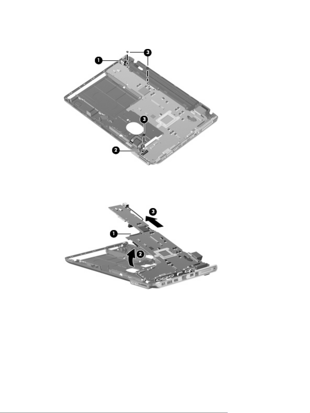
3. Remove the three Phillips PM2.5×4.0 screws (3) that secure the system board to the base
enclosure.
4. Use the optical drive connector (1) to lift the left edge of the system board (2) until it rests at an
angle.
5. Remove the system board (3) from the base enclosure by sliding it up and to the left at an angle.
Reverse the preceding procedure to install the system board.
Component replacement procedures 53
Page 62

Speakers
Description Spare part number
Speakers 506955-001
Before removing the speakers, follow these steps:
1. Shut down the computer. If you are unsure whether the computer is off or in Hibernation, turn the
2. Disconnect all external devices connected to the computer.
3. Disconnect the power from the computer by first unplugging the power cord from the AC outlet and
computer on, and then shut it down through the operating system.
then unplugging the AC adapter from the computer.
4. Remove the battery (see
Battery on page 32).
5. Remove the following components:
a. Optical drive (see
b. Hard drive (see
c. Keyboard and switch cover (see
d. Display assembly (see
e. Top cover (see
f. System board (see
Optical drive on page 35)
Hard drive on page 38)
Keyboard and switch cover on page 40)
Display assembly on page 43)
Top cover on page 49)
System board on page 52)
Remove the speakers:
1. Disconnect the speaker cable from the system board (1).
2. Remove the two Phillips PM2.5×4.0 screws (2) that secure the speakers to the base enclosure.
3. Remove the speakers from the base enclosure (3).
Reverse this procedure to install the speakers.
54 Chapter 4 Removal and replacement procedures
Page 63

Bluetooth module
NOTE: The Bluetooth module spare part kit does not include a Bluetooth module cable. The Bluetooth
module cable is included in the Cable Kit, spare part number 468827-001.
Description Spare part number
Bluetooth module (includes double-sided tape) 398393-002
Before removing the Bluetooth module, follow these steps:
1. Shut down the computer. If you are unsure whether the computer is off or in Hibernation, turn the
computer on, and then shut it down through the operating system.
2. Disconnect all external devices connected to the computer.
3. Disconnect the power from the computer by first unplugging the power cord from the AC outlet and
then unplugging the AC adapter from the computer.
4. Remove the battery (see
Battery on page 32).
5. Remove the following components:
a. Optical drive (see
b. Hard drive (see
c. Keyboard and switch cover (see
d. Display assembly (see
e. Top cover (see
f. System board (see
Optical drive on page 35)
Hard drive on page 38)
Keyboard and switch cover on page 40)
Display assembly on page 43)
Top cover on page 49)
System board on page 52)
Remove the Bluetooth module:
1. Disconnect the Bluetooth cable from the system board (1).
2. Remove the Phillips PM2.0×3.0 screw (2) that secures the Bluetooth module to the base enclosure.
Component replacement procedures 55
Page 64

3. Remove the Bluetooth module from the base enclosure (3).
Reverse this procedure to install the Bluetooth module.
56 Chapter 4 Removal and replacement procedures
Page 65

RTC battery
NOTE: Removing the RTC battery and leaving it uninstalled for 5 or more minutes causes all
passwords and CMOS settings to be cleared.
Description Spare part number
RTC battery (includes double-sided tape) 486835-001
Before removing the RTC battery, follow these steps:
1. Shut down the computer. If you are unsure whether the computer is off or in Hibernation, turn the
computer on, and then shut it down through the operating system.
2. Disconnect all external devices connected to the computer.
3. Disconnect the power from the computer by first unplugging the power cord from the AC outlet and
then unplugging the AC adapter from the computer.
4. Remove the battery (see
Battery on page 32).
Remove the RTC battery:
1. Turn the computer upside down, and remove the WLAN module cover (see
on page 33).
2. Disconnect the RTC battery cable (1) from the system board.
3. Remove the RTC battery (2).
NOTE: The RTC battery is attached to the system board with double-sided tape.
WLAN module
Reverse this procedure to install the RTC battery.
Component replacement procedures 57
Page 66

Fan/heat sink assembly
Description Spare part number
Fan/heat sink assembly (includes replacement thermal material) 506960-001
Before removing the fan/heat sink assembly, follow these steps:
1. Shut down the computer. If you are unsure whether the computer is off or in Hibernation, turn the
computer on, and then shut it down through the operating system.
2. Disconnect all external devices connected to the computer.
3. Disconnect the power from the computer by first unplugging the power cord from the AC outlet and
then unplugging the AC adapter from the computer.
4. Remove the battery (see
Battery on page 32).
5. Remove the following components:
a. Optical drive (see
b. Hard drive (see
c. Keyboard and switch cover (see
d. Display assembly (see
e. Top cover (see
f. System board (see
Optical drive on page 35)
Hard drive on page 38)
Keyboard and switch cover on page 40)
Display assembly on page 43)
Top cover on page 49)
System board on page 52)
Remove the fan/heat sink assembly:
1. Turn the system board upside down, with the battery connector toward you.
2. Disconnect the fan cable (1) from the system board.
3. Loosen the three Phillips PM2.0×8.0 captive screws (2) that secure the fan/heat sink assembly to
the system board.
NOTE: Due to the adhesive quality of the thermal material located between the heat sink and
system board components, it may be necessary to move the heat sink from side to side to detach
the assembly.
58 Chapter 4 Removal and replacement procedures
Page 67
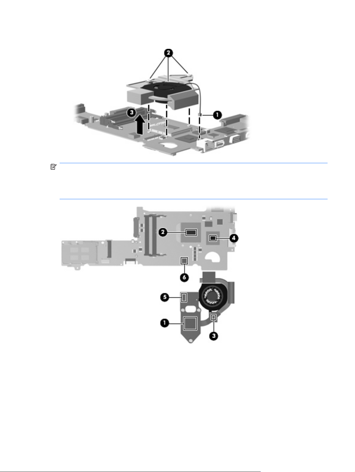
4. Remove the fan/heat sink assembly (3).
NOTE: The thermal material must be thoroughly cleaned from the surfaces of the fan/heat sink
assembly (1), (3), and (5); the processer (2); capacitor (6); and the graphics chip (4) each time the heat
sink is removed. Thermal pads and thermal paste must be installed on all surfaces before the heat sink
is reinstalled. Thermal pads and thermal paste are included with all heat sink, system board, and
processor spare part kits.
Reverse this procedure to install the fan/heat sink assembly.
Component replacement procedures 59
Page 68

Processor
NOTE: All processor spare part kits include replacement thermal material.
Description Spare part number
AMD Turion Ultra Dual-Core ZM-86 2.40-GHz processor (35W, 2-MB L2 cache) 506148-001
AMD Turion Ultra Dual-Core ZM-84 2.30-GHz processor (35W, 2-MB L2 cache) 506149-001
AMD Turion Ultra Dual-Core ZM-82 2.20-GHz processor (35W, 2-MB L2 cache) 506150-001
AMD Turion Dual-Core RM-74 2.20-GHz processor (35W, 1-MB L2 cache) 506151-001
AMD Turion Dual-Core RM-72 2.10-GHz processor (35W, 1-MB L2 cache) 506152-001
AMD Athlon X2 Dual-Core QL-64 2.10-GHz processor (35W, 1-MB L2 cache) 506153-001
AMD Athlon X2 Dual-Core QL-62 2.00-GHz processor (35W, 1-MB L2 cache) 506154-001
Before removing the processor, follow these steps:
1. Shut down the computer. If you are unsure whether the computer is off or in Hibernation, turn the
2. Disconnect all external devices connected to the computer.
computer on, and then shut it down through the operating system.
3. Disconnect the power from the computer by first unplugging the power cord from the AC outlet and
then unplugging the AC adapter from the computer.
4. Remove the battery (see
Battery on page 32).
5. Remove the following components:
a. Optical drive (see
b. Hard drive (see
c. Keyboard and switch cover (see
d. Display assembly (see
e. Top cover (see
f. System board (see
g. Fan/heat sink assembly (see
Optical drive on page 35)
Hard drive on page 38)
Keyboard and switch cover on page 40)
Display assembly on page 43)
Top cover on page 49)
System board on page 52)
Fan/heat sink assembly on page 58)
Remove the processor:
1. Turn the processor locking screw (1) one-half turn counterclockwise until you hear a click.
60 Chapter 4 Removal and replacement procedures
Page 69

2. Lift the processor (2) straight up and remove it.
NOTE: When you install the processor, the gold triangle (3) on the processor must be aligned
with the triangle icon (4) embossed on the processor slot.
Reverse this procedure to install the processor.
Component replacement procedures 61
Page 70

5 Setup Utility
Starting the Setup Utility
The Setup Utility is a ROM-based information and customization utility that can be used even when your
Windows® operating system is not working.
NOTE: The fingerprint reader (select models only) cannot be used to access the Setup Utility.
The utility reports information about the computer and provides settings for startup, security, and other
preferences.
To start the Setup Utility:
Open the Setup Utility by turning on or restarting the computer. While the “Press the ESC key for
Startup Menu” message is displayed in the lower-left corner of the screen, press f10.
– or –
1. Open the Setup Utility by turning on or restarting the computer. While the “Press the ESC key for
Startup Menu” message is displayed in the lower-left corner of the screen, press esc.
2. When the Startup Menu is displayed, press f10.
Changing the language of the Setup Utility
The following procedure explains how to change the language of the Setup Utility. If the Setup Utility is
not already running, begin at step 1. If the Setup Utility is already running, begin at step 2.
1. Open the Setup Utility by turning on or restarting the computer. While the “Press the ESC key for
Startup Menu” message is displayed in the lower-left corner of the screen, press f10.
– or –
Open the Setup Utility by turning on or restarting the computer. While the “Press the ESC key for
Startup Menu” message is displayed in the lower-left corner of the screen, press esc. When the
Startup Menu is displayed, press f10.
2. Use the arrow keys to select System Configuration > Language, and then press enter.
3. Use the arrow keys to select a language, and then press enter.
4. When a confirmation prompt with your language selected is displayed, press enter.
5. To save your change and exit the Setup Utility, use the arrow keys to select Exit > Exit Saving
Changes, and then press enter.
62 Chapter 5 Setup Utility
Page 71

Your change goes into effect immediately.
Navigating and selecting in the Setup Utility
Because the Setup Utility is not Windows based, it does not support the TouchPad. Navigation and
selection are by keystroke.
To choose a menu or a menu item, use the arrow keys.
●
To choose an item in a list or to toggle a field, for example an Enable/Disable field, use either the
●
arrow keys or f5 or f6.
To select an item, press enter.
●
To close a text box or return to the menu display, press esc.
●
To display additional navigation and selection information while the Setup Utility is open, press
●
f1.
Displaying system information
The following procedure explains how to display system information in the Setup Utility. If the Setup
Utility is not open, begin at step 1. If the Setup Utility is open, begin at step 2.
1. Open the Setup Utility by turning on or restarting the computer. While the “Press the ESC key for
Startup Menu” message is displayed in the lower-left corner of the screen, press f10.
– or –
Open the Setup Utility by turning on or restarting the computer. While the “Press the ESC key for
Startup Menu” message is displayed in the lower-left corner of the screen, press esc. When the
Startup Menu is displayed, press f10.
2. Select the Main menu. System information such as the system time and date, and identification
information about the computer is displayed.
3. To exit the Setup Utility without changing any settings, use the arrow keys to select Exit > Exit
Discarding Changes, and then press enter.
Restoring default settings in the Setup Utility
The following procedure explains how to restore the Setup Utility default settings. If the Setup Utility is
not already running, begin at step 1. If the Setup Utility is already running, begin at step 2.
1. Open the Setup Utility by turning on or restarting the computer. While the “Press the ESC key for
Startup Menu” message is displayed in the lower-left corner of the screen, press f10.
– or –
Open the Setup Utility by turning on or restarting the computer. While the “Press the ESC key for
Startup Menu” message is displayed in the lower-left corner of the screen, press esc. When the
Startup Menu is displayed, press f10.
2. Use the arrow keys to select Exit > Load Setup Defaults, and then press enter.
Navigating and selecting in the Setup Utility 63
Page 72

3. When the Setup Confirmation is displayed, press enter.
4. To save your change and exit the Setup Utility, use the arrow keys to select Exit > Exit Saving
Changes, and then press enter.
The Setup Utility default settings go into effect when the computer restarts.
NOTE: Your password, security, and language settings are not changed when you restore the factory
default settings.
Exiting the Setup Utility
You can exit the Setup Utility with or without saving changes.
To exit the Setup Utility and save your changes from the current session:
●
If the Setup Utility menus are not visible, press esc to return to the menu display. Then use the
arrow keys to select Exit > Exit Saving Changes, and then press enter.
To exit the Setup Utility without saving your changes from the current session:
●
If the Setup Utility menus are not visible, press esc to return to the menu display. Then use the
arrow keys to select Exit > Exit Discarding Changes, and then press enter.
After either choice, the computer restarts in Windows.
Setup Utility menus
The menu tables in this section provide an overview of Setup Utility options.
NOTE: Some of the Setup Utility menu items listed in this chapter may not be supported by your
computer.
Main menu
Select To do this
System information
Security menu
Select To do this
Administrator password Enter, change, or delete an administrator password.
Power-On Password Enter, change, or delete a power-on password.
View and change the system time and date.
●
View identification information about the computer.
●
View specification information about the processor, memory size,
●
system BIOS, and keyboard controller version (select models only).
64 Chapter 5 Setup Utility
Page 73

System Configuration menu
Select To do this
Language Support Change the Setup Utility language.
Button Sound (select models only) Enable/disable the capacitive button tapping sound.
Virtualization Technology Enable/disable the processor Virtualization Technology.
Processor C6 State (select models only) Enable/disable the processor C6 sleep state.
LAN Power Saving (select models only) Enable/disable LAN Power Saving. When enabled, saves power when
the computer is in DC mode.
Card Reader/1394 Power Saving (select models
only)
Fan Always On Enabled/disable Fan Always On. When enabled, the computer fan will
Boot Options Set the following boot options:
Enable/disable Card Reader/1394 Power Saving. When enabled, saves
power when the computer is in DC mode.
always be on.
f9 and f10 Delay (sec.)―Set the delay for the f9 and f10 functions
●
of the Setup Utility in intervals of 5 seconds each (0, 5, 10, 15, 20).
CD-ROM boot―Enable/disable boot from CD-ROM.
●
Floppy boot―Enable/disable boot from diskette.
●
Internal Network Adapter boot―Enable/disable boot from Internal
●
Network Adapter.
Boot Order―Set the boot order for:
●
USB Floppy
◦
Internal CD/DVD ROM Drive
◦
Hard drive
◦
USB Diskette on Key
◦
USB Hard drive
◦
Network adapter
◦
Diagnostics menu
Select To do this
Hard Disk Self Test Run a comprehensive self-test on the hard drive.
Secondary Hard Disk Self Test (select models
only)
Memory Test Run a diagnostic test on the system memory.
NOTE: On models with two hard drives, this menu option is called the
Primary Hard Disk Self Test.
Run a comprehensive self-test on a secondary hard drive.
Setup Utility menus 65
Page 74

6 Specifications
Computer specifications
Metric U.S.
Dimensions
Length
Width 31.20 cm 12.28 in
Height (front to rear) 2.59 to 3.24 cm 1.02 to 1.28 in
Weight (with optical drive, hard drive, and battery) 1.81 kg 4.00 lbs
Input power
Operating voltage
Operating current 3.5 A or 4.74 A
Temperature
Operating
Nonoperating -20°C to 60°C -4°F to 140°F
Relative humidity
Operating
Nonoperating 5% to 95%
Maximum altitude (unpressurized)
Operating
Nonoperating -15 m to 12,192 m -50 ft to 40,000 ft
23.00 cm 9.05 in
18.5 V dc —19.0 V dc
5°C to 35°C 41°F to 95°F
10% to 90%
-15 m to 3,048 m -50 ft to 10,000 ft
NOTE: Applicable product safety standards specify thermal limits for plastic surfaces. The computer operates well within this
range of temperatures.
66 Chapter 6 Specifications
Page 75

13.3-inch, WXGA, BrightView display specifications
Metric U.S.
Dimensions
Height
Width 28.7 cm 11.3 in
Diagonal 33.9 cm 13.4 in
Number of colors Up to 16.8 million
Contrast ratio 250:1 (typical)
Brightness 180 nits (typical)
Pixel resolution
Pitch
Format 1280 × 800
Configuration RGB vertical stripe
Backlight Edge lit
Character display 80 × 25
Total power consumption 4.0 W
Viewing angle +/-40° horizontal, +120/-40° vertical (typical)
18.0 cm 7.1 in
0.279 × 0.279 mm
13.3-inch, WXGA, BrightView display specifications 67
Page 76

Hard drive specifications
500-GB* 400-GB* 320-GB* 250-GB* 160-GB*
Dimensions
Height
Width 70 mm 70 mm 70 mm 70 mm 70 mm
Weight 102 g 102 g 102 g 102 g 102 g
Interface type SATA SATA SATA SATA SATA
Transfer rate
Synchronous (maximum)
Security ATA security ATA security ATA security ATA security ATA security
Seek times (typical read, including setting)
Single track
Average 13 ms 13 ms 13 ms 13 ms 13 ms
Maximum 24 ms 24 ms 24 ms 24 ms 24 ms
Logical blocks 1,048,576,000 838,860,800 645,126,482 500,586,425 312,581,808
Disk rotational speed 5400 rpm
Operating temperature 5°C to 55°C (41°F to 131°F)
NOTE: Certain restrictions and exclusions apply. Consult technical support for details.
*1 GB = 1 billion bytes when referring to hard drive storage capacity. Accessible capacity is less. Actual drive specifications
may differ slightly.
9.5 mm 9.5 mm 9.5 mm 9.5 mm 9.5 mm
100 MB/sec 100 MB/sec 100 MB/sec 100 MB/sec 100 MB/sec
3 ms 3 ms 3 ms 3 ms 3 ms
68 Chapter 6 Specifications
Page 77

DVD±RW and CD-RW SuperMulti Double-Layer Combo Drive specifications
Applicable disc Read:
CD-DA, CD+(E)G, CD-MIDI, CD-TEXT,
CD-ROM, CD-ROM XA, MIXED MODE
CD, CD-I, CD-I Bridge (Photo-CD, Video
CD), Multisession CD (Photo-CD, CDEXTRA, Portfolio, CD-R, CD-RW), CD-R,
CD-RW, DVD-ROM (DVD-5, DVD-9,
DVD-10, DVD-18), DVD-R, DVD-RW,
DVD+R, DVD+RW, DVD-RAM
Access time CD DVD
Random < 175 ms < 230 ms
Cache buffer 2 MB
Data transfer rate
24X CD-ROM
8X DVD 10,800 KB/sec
24X CD-R 3,600 KB/sec
16X CD-RW 2,400 KB/sec
8X DVD+R 10,800 KB/sec
4X DVD+RW 5,400 KB/sec
3,600 KB/sec
Write:
CD-R and CD-RW
DVD+R, DVD+RW, DVD-R, DVD-RW,
DVD-RAM
8X DVD-R 10,800 KB/sec
4X DVD-RW 5,400 KB/sec
2.4X DVD+R(9) 2,700 KB/sec
5X DVD-RAM 6,750 KB/sec
Transfer mode Multiword DMA Mode
DVD±RW and CD-RW SuperMulti Double-Layer Combo Drive specifications 69
Page 78

System DMA specifications
Hardware DMA System function
DMA0 Not applicable
DMA1* Not applicable
DMA2* Not applicable
DMA3 Not applicable
DMA4 Direct memory access controller
DMA5* Available for PC Card
DMA6 Not assigned
DMA7 Not assigned
*PC Card controller can use DMA 1, 2, or 5.
System memory map specifications
Size Memory address System function
640 KB 00000000-0009FFFF Base memory
128 KB 000A0000-000BFFFF Video memory
48 KB 000C0000-000CBFFF Video BIOS
160 KB 000C8000-000E7FFF Unused
64 KB 000E8000-000FFFFF System BIOS
15 MB 00100000-00FFFFFF Extended memory
58 MB 04800000-07FFFFFF Super extended memory
58 MB 04800000-07FFFFFF Unused
2 MB 08000000-080FFFFF Video memory (direct access)
4 GB 08200000-FFFEFFFF Unused
64 KB FFFF0000-FFFFFFFF System BIOS
70 Chapter 6 Specifications
Page 79

System interrupt specifications
Hardware IRQ System function
IRQ0 System timer
IRQ1 Standard 101-/102-Key or Microsoft® Natural Keyboard
IRQ2 Cascaded
IRQ3 Intel 82801DB/DBM USB2 Enhanced Host Controller—24CD
IRQ4 COM1
IRQ5* Conexant AC—Link Audio Intel 82801DB/DBM SMBus Controller—24C3 Data Fax
Modem with SmartCP
IRQ6 Diskette drive
IRQ7* Parallel port
IRQ8 System CMOS/real-time clock
IRQ9* Microsoft ACPI-compliant system
IRQ10* Intel USB UHCI controller—24C2
Intel 82852/82855 GM/GME Graphic Controller
Realtek RTL8139 Family PCI Fast Ethernet Controller
IRQ11 Intel USB EHCI controller—24CD
Intel USB UHCI controller—24C4
Intel USB UHCI controller—24C7
Intel Pro/Wireless 2200BG
TI OHCI 1394 host controller
TI PCI1410 CardBus controller
IRQ12 Synaptics PS/2 TouchPad
IRQ13 Numeric data processor
IRQ14 Primary IDE channel
IRQ15 Secondary IDE channel
*Default configuration; audio possible configurations are IRQ5, IRQ7, IRQ9, IRQ10, or none.
NOTE: PC Cards may assert IRQ3, IRQ4, IRQ5, IRQ7, IRQ9, IRQ10, IRQ11, or IRQ15. Either the infrared or the serial port
may assert IRQ3 or IRQ4.
System interrupt specifications 71
Page 80

System I/O address specifications
I/O address (hex) System function (shipping configuration)
000 - 00F DMA controller no. 1
010 - 01F Unused
020 - 021 Interrupt controller no. 1
022 - 024 Opti chipset configuration registers
025 - 03F Unused
02E - 02F 87334 “Super I/O” configuration for CPU
040 - 05F Counter/timer registers
044 - 05F Unused
060 Keyboard controller
061 Port B
062 - 063 Unused
064 Keyboard controller
065 - 06F Unused
070 - 071 NMI enable/RTC
072 - 07F Unused
080 - 08F DMA page registers
090 - 091 Unused
092 Port A
093 - 09F Unused
0A0 - 0A1 Interrupt controller no. 2
I/O Address (hex) System function (shipping configuration)
0A2 - 0BF Unused
0C0 - 0DF DMA controller no. 2
0E0 - 0EF Unused
0F0 - 0F1 Coprocessor busy clear/reset
0F2 - 0FF Unused
100 - 16F Unused
170 - 177 Secondary fixed disk controller
178 - 1EF Unused
1F0 - 1F7 Primary fixed disk controller
1F8 - 200 Unused
201 JoyStick (decoded in ESS1688)
202 - 21F Unused
72 Chapter 6 Specifications
Page 81

I/O address (hex) System function (shipping configuration)
220 - 22F Entertainment audio
230 - 26D Unused
26E - 26 Unused
278 - 27F Unused
280 - 2AB Unused
2A0 - 2A7 Unused
2A8 - 2E7 Unused
2E8 - 2EF Reserved serial port
2F0 - 2F7 Unused
2F8 - 2FF Infrared port
300 - 31F Unused
320 - 36F Unused
370 - 377 Secondary diskette drive controller
378 - 37F Parallel port (LPT1/default)
380 - 387 Unused
388 - 38B FM synthesizer—OPL3
38C - 3AF Unused
3B0 - 3BB VGA
3BC - 3BF Reserved (parallel port/no EPP support)
3C0 - 3DF VGA
3E0 - 3E1 PC Card controller in CPU
3E2 - 3E3 Unused
3E8 - 3EF Internal modem
3F0 - 3F7 “A” diskette controller
3F8 - 3FF Serial port (COM1/default)
CF8 - CFB PCI configuration index register (PCIDIVO-1)
CFC - CFF PCI configuration data register (PCIDIVO-1)
System I/O address specifications 73
Page 82

7 Screw listing
This section provides specification and reference information for the screws and screw locks used in
the computer. All screws and screw locks listed in this section are available in either the Screw Kit, spare
part number 506961-001, or the Display Screw Kit, spare part number 506228-001.
Phillips PM2.0×2.0 broadhead screw
Color Quantity Length Thread Head diameter
Black 2 2.0 mm 2.0 mm 5.0 mm
Where used: Two screws that secure the fingerprint reader board to the top cover
74 Chapter 7 Screw listing
Page 83

Phillips PM2.0×3.0 captive screw
Color Quantity Length Thread Head diameter
Silver 5 3.0 mm 2.0 mm 4.5 mm
Where used: Four screws that secure the display panel to the display enclosure
Where used: One screw that secures the Bluetooth module to the computer
Phillips PM2.0×3.0 captive screw 75
Page 84
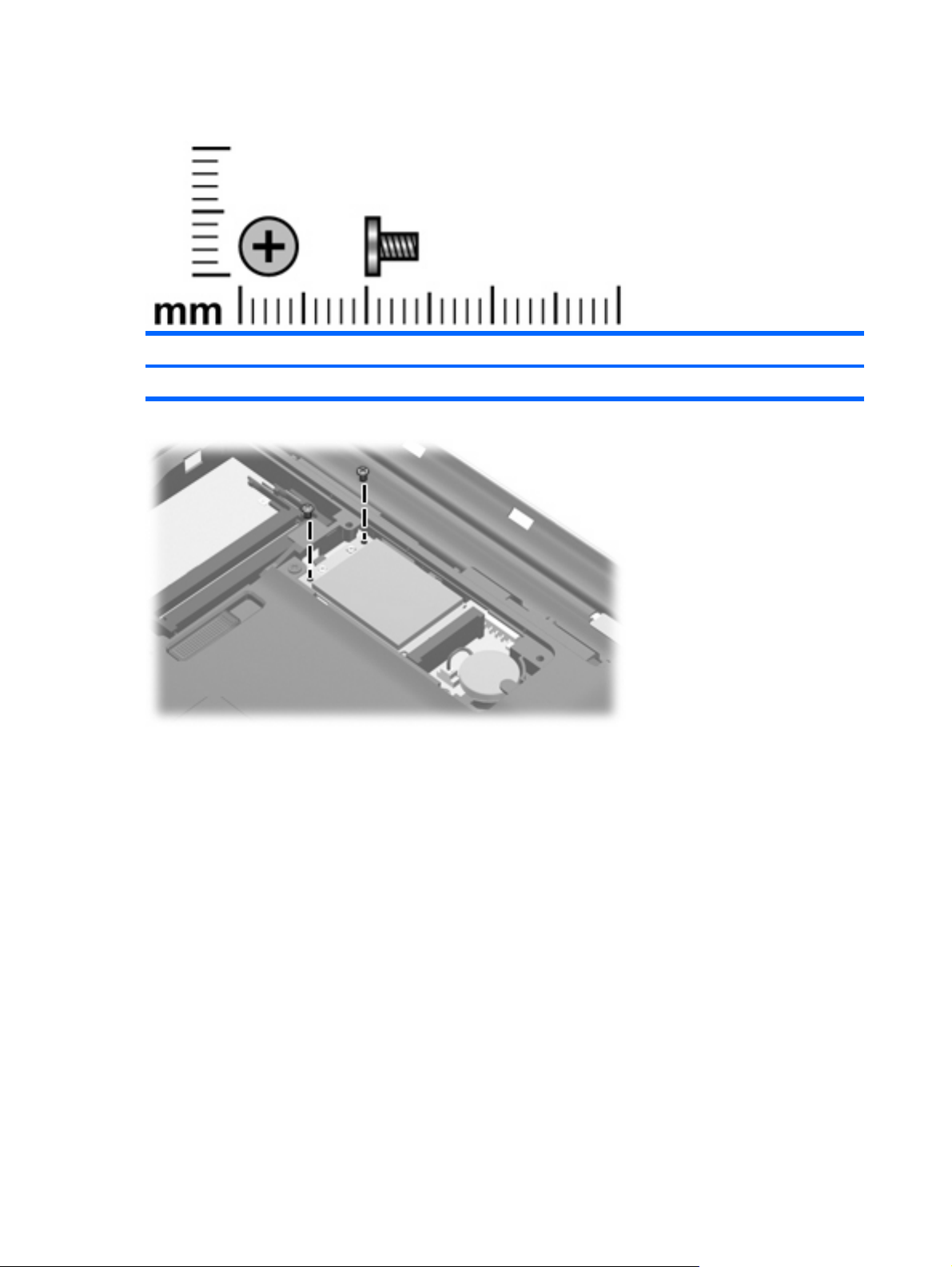
Phillips PM2.0×4.0 screw
Color Quantity Length Thread Head diameter
Silver 2 4.0 mm 2.0 mm 4.5 mm
Where used: Two screws that secure the WLAN module to the computer
76 Chapter 7 Screw listing
Page 85

Phillips PM2.0×8.0 captive screw
Color Quantity Length Thread Head diameter
Black 3 8.0 mm 2.0 mm 5.0 mm
Where used: Three captive screws (secured by C-clips) that secure the heat sink retention clip to the
heat sink
Phillips PM2.0×8.0 captive screw 77
Page 86

Phillips PM2.5×4.0 screw
Color Quantity Length Thread Head diameter
Silver 8 4.0 mm 2.5 mm 4.5 mm
Where used: Two screws that secure the hard drive to the computer
Where used: One screw that secures the power button board to the switch cover
78 Chapter 7 Screw listing
Page 87

Where used: Two screws that secure the speakers to the computer
Where used: Three screws that secure the system board to the computer
Phillips PM2.5×4.0 screw 79
Page 88
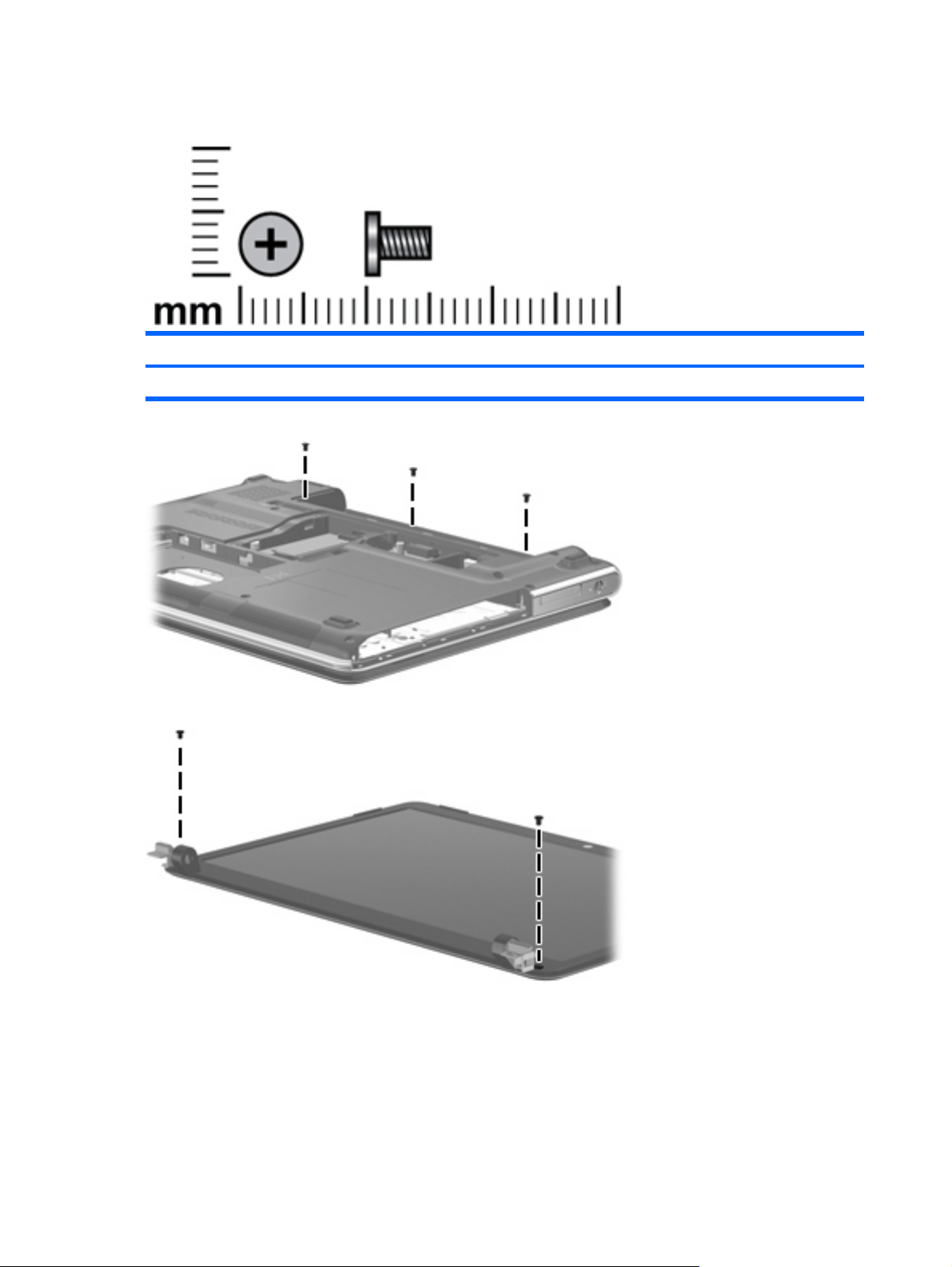
Phillips PM2.5×5.0 screw
Color Quantity Length Thread Head diameter
Black 7 5.0 mm 2.5 mm 5.0 mm
Where used: Three screws that secure the switch cover to the computer
Where used: Two screws that secure the display bezel to the display
80 Chapter 7 Screw listing
Page 89
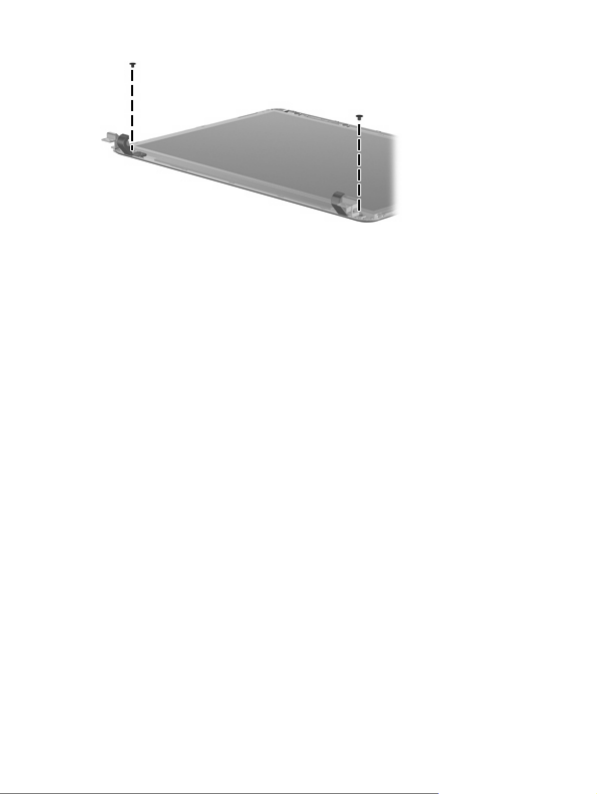
Where used: Two screws that secure the display hinges to the display
Phillips PM2.5×5.0 screw 81
Page 90

Phillips PM2.5×6.0 captive screw
Color Quantity Length Thread Head diameter
Black 5 6.0 mm 2.5 mm 5.0 mm
Where used:
(1) Two captive screws (secured by a C-clip) that secure the WLAN compartment cover to the computer
(2) Two captive screws (secured by C-clips) that secure the memory module compartment cover to the
computer
(3) One captive screw (secured by C-clips) that secures the hard drive cover to the computer
82 Chapter 7 Screw listing
Page 91

Phillips PM2.5×7.0 screw
Color Quantity Length Thread Head diameter
Black 16 7.0 mm 2.5 mm 5.0 mm
Where used: Six screws that secure the switch cover to the computer
Where used: Three screws that secure the keyboard to the computer
Phillips PM2.5×7.0 screw 83
Page 92
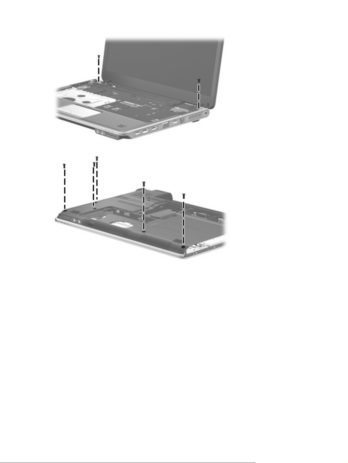
Where used: Two screws that secure the display assembly to the computer
Where used: Five screws that secure the top cover to the base enclosure
84 Chapter 7 Screw listing
Page 93

8 Backup and recovery
Recovering system information
Recovery after a system failure is as complete as your most current backup. HP recommends that you
create recovery discs immediately after software setup. As you add new software and data files, you
should continue to back up your system on a regular basis to maintain a reasonably current backup.
Tools provided by the operating system and HP Recovery Manager software are designed to help you
with the following tasks for safeguarding your information and restoring it in case of a system failure:
Creating a set of recovery discs (Recovery Manager software feature). Recovery discs are used
●
to start up (boot) your computer and restore the operating system and software programs to factory
settings in case of system failure or instability.
Backing up your information regularly to protect your important system files.
●
Creating system restore points (operating system feature). System restore points allow you to
●
reverse undesirable changes to your computer by restoring the computer to an earlier state.
Recovering a program or driver (Recovery Manager software feature). This feature helps you
●
reinstall a program or driver without performing a full system recovery.
Performing a full system recovery (Recovery Manager software feature). With Recovery Manager,
●
you can recover your full factory image if you experience system failure or instability. Recovery
Manager works from a dedicated recovery partition (select models only) on the hard drive or from
recovery discs you create.
NOTE: If your computer includes a solid-state drive (SSD), you may not have a recovery partition.
Recovery discs have been included for computers that do not have a partition. Use these discs to
recover your operating system and software. To check for the presence of a recovery partition,
select Start > Computer. If the partition is present, an HP Recovery drive is listed in the Hard Disk
Drives section of the window.
Creating recovery discs
NOTE: HP recommends that you create recovery discs to be sure that you can restore your system
to its original factory state if you experience serious system failure or instability. Create these discs after
setting up the computer for the first time.
NOTE: Handle these discs carefully and keep them in a safe place. The software allows the creation
of only one set of recovery discs.
Recovering system information 85
Page 94

Note the following guidelines before creating recovery discs:
You will need high-quality DVD-R, double-layer DVD-R, DVD+R, double-layer DVD+R, BD-R
●
(writable Blu-ray), or CD-R discs. All these discs are purchased separately. DVDs and BDs have
a much higher capacity than CDs. If you use CDs, up to 20 discs may be required, whereas only
a few DVDs or BDs are required.
NOTE: Read-write discs, such as CD-RW, DVD±RW, double-layer DVD±RW, and BD-RE
(rewritable Blu-ray) discs, are not compatible with the Recovery Manager software.
The computer must be connected to AC power during this process.
●
Only one set of recovery discs can be created per computer.
●
Number each disc before inserting it into the computer optical drive.
●
If necessary, you can exit the program before you have finished creating the recovery discs. The
●
next time you open Recovery Manager, you will be prompted to continue the disc creation process.
To create a set of recovery discs:
1. Select Start > All Programs > Recovery Manager > Recovery Manager.
Recovery Manager opens.
2. Click Advanced Options.
NOTE: If you are operating the computer on battery power, you will be prompted to connect to
AC power before you can go to the next step.
3. Click Recovery disc creation, and then click Next.
4. Follow the on-screen instructions.
Backing up your information
When to back up
On a regularly scheduled basis
●
NOTE: Set reminders to back up your information periodically.
Before the computer is repaired or restored
●
Before you add or modify hardware or software
●
Backup suggestions
Create a set of recovery discs using Recovery Manager.
●
Create system restore points using the Windows® System Restore feature, and periodically copy
●
them to disc.
Store personal files in the Documents folder and back up these folders periodically.
●
Back up templates stored in their associated programs.
●
Save customized settings in a window, toolbar, or menu bar by taking a screen shot of your settings.
●
The screen shot can be a time saver if you have to reset your preferences.
86 Chapter 8 Backup and recovery
Page 95

To copy the screen and paste it into a word-processing document, follow these steps:
a. Display the screen.
b. Copy the screen:
To copy only the active window, press alt+fn+prt sc.
To copy the entire screen, press fn+prt sc.
c. Open a word-processing document, and then select Edit > Paste.
Using system restore points
When you back up your system, you are creating a system restore point. A system restore point allows
you to save and name a snapshot of your hard drive at a specific point in time. You can then recover
back to that point if you want to reverse subsequent changes made to your system.
NOTE: Recovering to an earlier restore point does not affect data files saved or e-mails created since
the last restore point.
You also can create additional restore points to provide increased protection for your system files and
settings.
When to create restore points
Before you add or extensively modify software or hardware
●
Periodically, whenever the system is performing optimally
●
NOTE: If you revert to a restore point and then change your mind, you can reverse the restoration.
Create a system restore point
1. Select Start > Control Panel > System and Maintenance > System.
2. In the left pane, click System protection.
3. Click the System Protection tab.
4. Under Automatic restore points, select the disk for which you want to create a restore point.
5. Click Create.
The System Protection window opens.
6. Follow the on-screen instructions.
Restore to a previous date and time
To revert to a restore point (created at a previous date and time), when the computer was functioning
optimally, follow these steps:
1. Select Start > Control Panel > System and Maintenance > System.
2. In the left pane, click System protection.
3. Click the System Protection tab.
Recovering system information 87
Page 96

4. Click the System Restore button, and then click Next.
The System Restore window opens.
5. Follow the on-screen instructions.
Performing a recovery
NOTE: You can recover only files that you have previously backed up. HP recommends that you use
HP Recovery Manager to create an entire drive backup as soon as you set up your computer.
Recovery Manager software allows you to repair or restore the system if you experience system failure
or instability. Recovery Manager works from recovery discs that you create or from a dedicated recovery
partition (select models only) on the hard drive. However, if your computer includes a solid-state drive
(SSD), you may not have a recovery partition. If that is the case, recovery discs have been included
with your computer. Use these discs to recover your operating system and software.
NOTE: Windows has its own built-in repair features, such as System Restore and driver roll-back
capabilities. If you have not already tried these features, try them before using Recovery Manager.
NOTE: Recovery Manager recovers only software that was preinstalled at the factory. Software not
provided with this computer must be downloaded from the manufacturer's Web site or reinstalled from
the disc provided by the manufacturer.
Recovering from the recovery discs
To restore the system from the recovery discs:
1. Back up all personal files.
2. Insert the first recovery disc into the optical drive and restart the computer.
3. Follow the on-screen instructions.
Recovering from the dedicated recovery partition (select models only)
NOTE: If your computer includes an SSD, you may not have a recovery partition. You will not be able
to recover using this procedure. Recovery discs have been included for computers that do not have a
partition. Use these discs to recover your operating system and software.
On some models, you can perform a recovery from the partition on the hard drive from either the Start
button or f11. This restores the computer to its factory condition.
To restore the system from the partition, follow these steps:
1. Access Recovery Manager in either of the following ways:
Select Start > All Programs > Recovery Manager > Recovery Manager.
●
–or–
Restart the computer and press f11 while the “Press <F11> for recovery” message is displayed
●
on the screen. Then select Recovery Manager.
Recovery Manager opens.
2. Click Advanced Options.
88 Chapter 8 Backup and recovery
Page 97

3. Click System recovery, and then click Next.
4. Follow the on-screen instructions.
Recovering system information 89
Page 98

9 Connector pin assignments
Audio-in (microphone)
Pin Signal
1 Audio signal in
2 Audio signal in
3Ground
Audio-out (headphone)
Pin Signal
1 Audio out, left channel
2 Audio out, right channel
3Ground
External monitor
90 Chapter 9 Connector pin assignments
Page 99

Pin Signal
1 Red analog
2 Green analog
3 Blue analog
4 Not connected
5 Ground
6 Ground analog
7 Ground analog
8 Ground analog
9 +5 VDC
10 Ground
11 Monitor detect
12 DDC 2B data
13 Horizontal sync
14 Vertical sync
15 DDC 2B clock
External monitor 91
Page 100

RJ-11 (modem)
Pin Signal
1 Unused
2 Tip
3 Ring
4 Unused
5 Unused
6Unused
RJ-45 (network)
Pin Signal
1 Transmit +
2 Transmit -
3 Receive +
4 Unused
5 Unused
6 Receive -
7 Unused
8Unused
92 Chapter 9 Connector pin assignments
 Loading...