

HP PAVILION ELITE M9565, PAVILION A6421, PAVILION A6455, PAVILION A6430, PAVILION ELITE M9543 User Manual
...
Advanced Setup Guide

The only warranties for Hewlett-Packard products and services are set forth in the express
statements accompanying such products and services. Nothing herein should be construed as
constituting an additional warranty. HP shall not be liable for technical or editorial errors or
omissions contained herein.
HP assumes no responsibility for the use or reliability of its software on equipment that is not
furnished by HP.
This document contains proprietary information that is protected by copyright. No part of this
document may be photocopied, reproduced, or translated to another language without the prior
written consent of HP.
Hewlett-Packard Company
P.O. Box 4010
Cupertino, CA 95015-4010
USA
Copyright © 2000–2007 Hewlett-Packard Development Company, L.P.
This product incorporates copyright protection technology that is protected by U.S. patents and
other intellectual property rights. Use of this copyright protection technology must be authorized by
Macrovision, and is intended for home and other limited pay-per-view viewing uses only unless
otherwise authorized by Macrovision. Reverse engineering or disassembly is prohibited.
Microsoft and Windows Vista are U.S. registered trademarks of Microsoft Corporation.
The Windows logo and Windows Vista are trademarks or registered trademarks of Microsoft
Corporation in the United States and/or other countries/regions.
HP supports lawful use of technology and does not endorse or encourage the use of our products
for purposes other than those permitted by copyright law.
The information in this document is subject to change without notice.

Table of Contents
Setting Up the Computer ..........................................................................1
Putting the Computer Together .................................................................................1
Placing the computer in the proper location ..........................................................1
Using surge protection .......................................................................................2
Connecting to the computer ................................................................................ 2
Connecting a Digital Camera (Photo or Video)...........................................................8
Connecting Other Devices .....................................................................................10
Storing Documentation and Recovery Discs..............................................................10
Adjusting the Monitor............................................................................................11
Adjusting the screen resolution by using Vista .....................................................11
Adjusting the screen resolution by using the NVIDIA Control Panel ........................11
Setting Up a Local Area Network ........................................................................... 12
Setting Up a Wired (Ethernet) Connection ...............................................................13
Integrated Wireless Devices...................................................................................13
Connecting the Wireless LAN Device......................................................................14
Checking the wireless LAN device installation .....................................................15
Using wireless security features .........................................................................15
Connecting a Modem ...........................................................................................16
Table of Contents iii

Connecting Speakers or Microphone ......................................................17
Sound Connector Types ........................................................................................17
Connecting a Microphone.....................................................................................20
Speaker Configurations.........................................................................................21
Speaker types .................................................................................................22
Connecting 2/2.1 (Two speakers and a subwoofer) audio speakers......................22
Connecting 4.1 (Four speakers and a subwoofer) audio speakers .........................23
Connecting 5.1 (Five speakers and a subwoofer) audio speakers..........................25
Connecting 7.1 (Seven speakers and a subwoofer) audio speakers .......................26
Connecting your home stereo system (optional) ................................................... 29
2.1 home stereo installation..............................................................................30
5.1 home audio installation ..............................................................................31
5.1 home audio installation procedure...............................................................31
7.1 home audio installation ..............................................................................33
7.1 home audio installation procedure...............................................................34
Connecting digital audio ..................................................................................35
Connecting Speakers Using the Creative Sound Blaster X-Fi Sound Card..................... 37
Connecting the speakers ..................................................................................37
Connecting the FlexiJack connector.................................................................... 38
Connecting the Television Signal and Video Cables.................................39
Using TV Cables...................................................................................................39
Audio and Video Cables and Adapters................................................................... 40
Connecting the TV Signal Source............................................................................41
Connecting a dual tuner ...................................................................................42
Connecting the Remote Sensor ...............................................................................43
Connecting the TV Signal Source When You Have an Existing Setup ..........................44
Wall to VCR to TV, using coaxial cable..............................................................44
Wall to cable TV set-top box or satellite box to VCR to TV, using coaxial cable .......45
Wall to cable TV set-top box or satellite box to VCR and TV, using
S-video cable or composite video cable between the box and the VCR or TV.......... 46
Using a TV as a Monitor .......................................................................................48
Cables for connecting the computer to a TV ........................................................48
Connecting the computer to a TV.......................................................................48
Viewing the computer desktop on a TV screen.....................................................49
Adjusting the screen resolution ..........................................................................49
Connecting more than one display ....................................................................49
Using the Windows Media Center Setup for Optional Setup of the TV Display............. 50
Disabling the TV-out Option ...................................................................................51
Disconnecting the TV.............................................................................................51
iv Advanced Setup Guide (features vary by model)

Connecting to a Monitor or High-Definition TV .........................................................51
Choosing the AV connection to use.................................................................... 51
Connecting an HDMI device .............................................................................53
Connecting a DVI device.................................................................................. 54
Connecting to a Standard TV.................................................................................55
Connecting to component video ........................................................................55
Connecting to S-video ......................................................................................56
Configuring the TV Tuner.......................................................................................56
Digital versus analog tuner ...............................................................................57
Initial configuration using Windows Media Center setup wizard ...........................57
Changing the tuner settings...............................................................................58
Index.....................................................................................................59
Table of Contents v

vi Advanced Setup Guide (features vary by model)

Setting Up the Computer
WARNING: The power supply is preset for the country/region in which you
purchased your computer. If you move, please check the voltage requirements
for your new location before plugging the computer into an AC power outlet.
WARNING: Please read “Safety Information” in the Limited Warranty
and Support Guide before installing and connecting the computer to
the electrical power system.
Putting the Computer Together
Follow the steps on the setup poster to set up the computer. Read the topics in this section
to learn more about the location of components and connectors on the computer, and to
learn about some setup alternatives.
Look in the computer box for printed details or updates regarding the computer.
Placing the computer in the proper location
When setting up your new computer, place it where ventilation openings are unobstructed.
Make sure that all connections are secure and that all cabling is out of the way. Do not
place cabling in walkways or where it can be stepped on or damaged from placing
furniture on it.
Setting Up the Computer 1
Using surge protection
Help protect the monitor, computer, and accessories by connecting all power cords for the
computer and peripheral devices (such as a monitor, printer, or scanner) to a surge
protection device, such as a power strip with surge protection or an uninterruptible power
supply (UPS). Many surge protection devices have surge protection inputs and outputs for
modem or telephone lines. Telephone lines are a common path for lightning spikes to get
into the system. Some surge protection devices have surge protection for television cable
connections as well. Use those if the computer has a television tuner installed.
Not all power strips provide surge protection; the power strip must be specifically labeled
as having this capability. Use a power strip whose manufacturer offers a damage
replacement policy that replaces the equipment if surge protection fails.
Connecting to the computer
Connect the main hardware devices, such as the monitor, keyboard, and mouse, to the
back of the computer. Other peripheral devices, such as a printer, scanner, or camera,
also plug into connectors on the back of the computer. Some computers also have
connectors on the front of the computer. The following table shows some, but not all,
connectors:
NOTE:
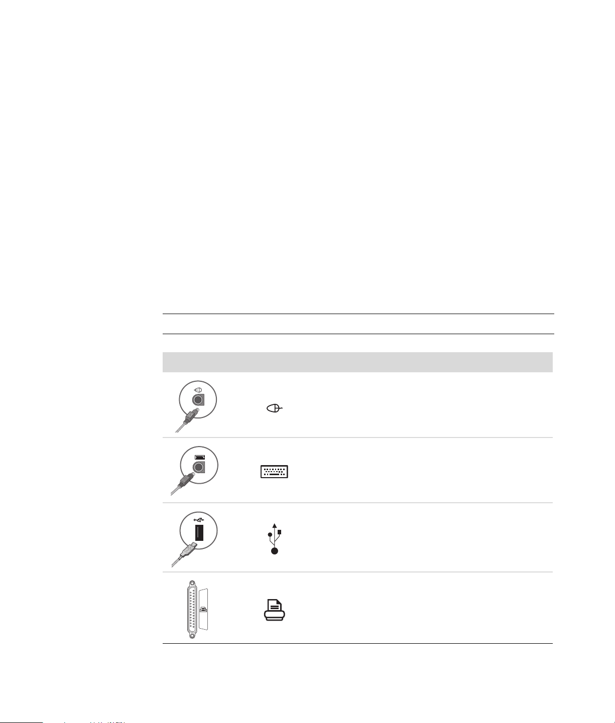
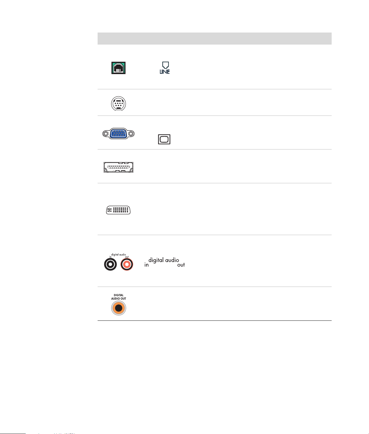
Connector Icon/Label Description and function
The location, availability, and number of connectors on the computer may vary.
Mouse (PS/2 connector).
Keyboard (PS/2 connector).
Universal Serial Bus (USB) for mouse, keyboard,
digital cameras, or other devices with USB
connectors.
Printer (parallel).
2 Advanced Setup Guide (features vary by model)
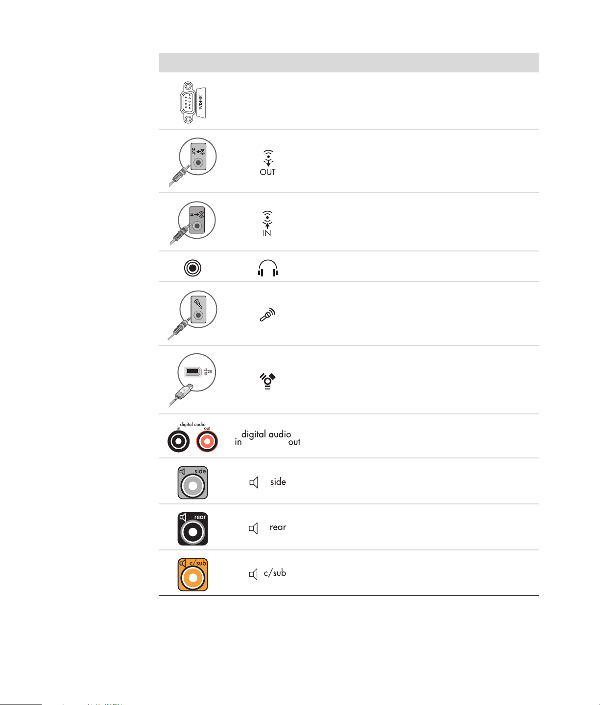
Connector Icon/Label Description and function (continued)
Serial port for some digital cameras or other
Serial
serial devices.
Audio Line Out (powered speakers).
Audio Line In.
Headphones.
Microphone.
®
FireWire
(IEEE 1394) for video cameras or other
devices with very fast transfer rates.
NOTE: You must use a 6-pin FireWire (IEEE 1394)
transfer cable with this 6-pin connector.
Digital audio in and digital audio out.
Side speaker out.
Rear speaker out.
Center/Subwoofer.
Setting Up the Computer 3
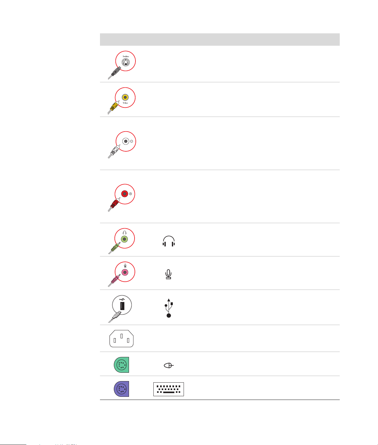
Connector Icon/Label Description and function (continued)
Secondary S-video connector to connect a VCR,
S-Video 2
video camera, or other analog source to the
computer.
Secondary Composite video connector (yellow) to
Composite
Video 2
connect to a VCR, video camera, or other analog
source to the computer.
Secondary Left audio input connector (white).
A/V In
Audio 2
L
A/V In
Audio 2
R
NOTE: This Audio In connector is connected to the
TV tuner. You must use the Audio In connector,
which is connected to the motherboard and located
on the back of the computer, to record audio only
(select models only).
Secondary Right audio input connector (red).
NOTE: This Audio In connector is connected to the
TV tuner. You must use the Audio In connector,
which is connected to the motherboard and located
on the back of the computer, to record audio only
(select models only).
Headphones Out connector (green) to connect to
headphones.
Microphone In connector (pink) to connect to a
microphone.
Universal Serial Bus (USB) 2.0 connector to connect
to a mouse, keyboard, digital camera, or another
device with a USB connector.
4 Advanced Setup Guide (features vary by model)
Power connector.
Mouse connector to connect a mouse.
Keyboard connector to connect a keyboard.

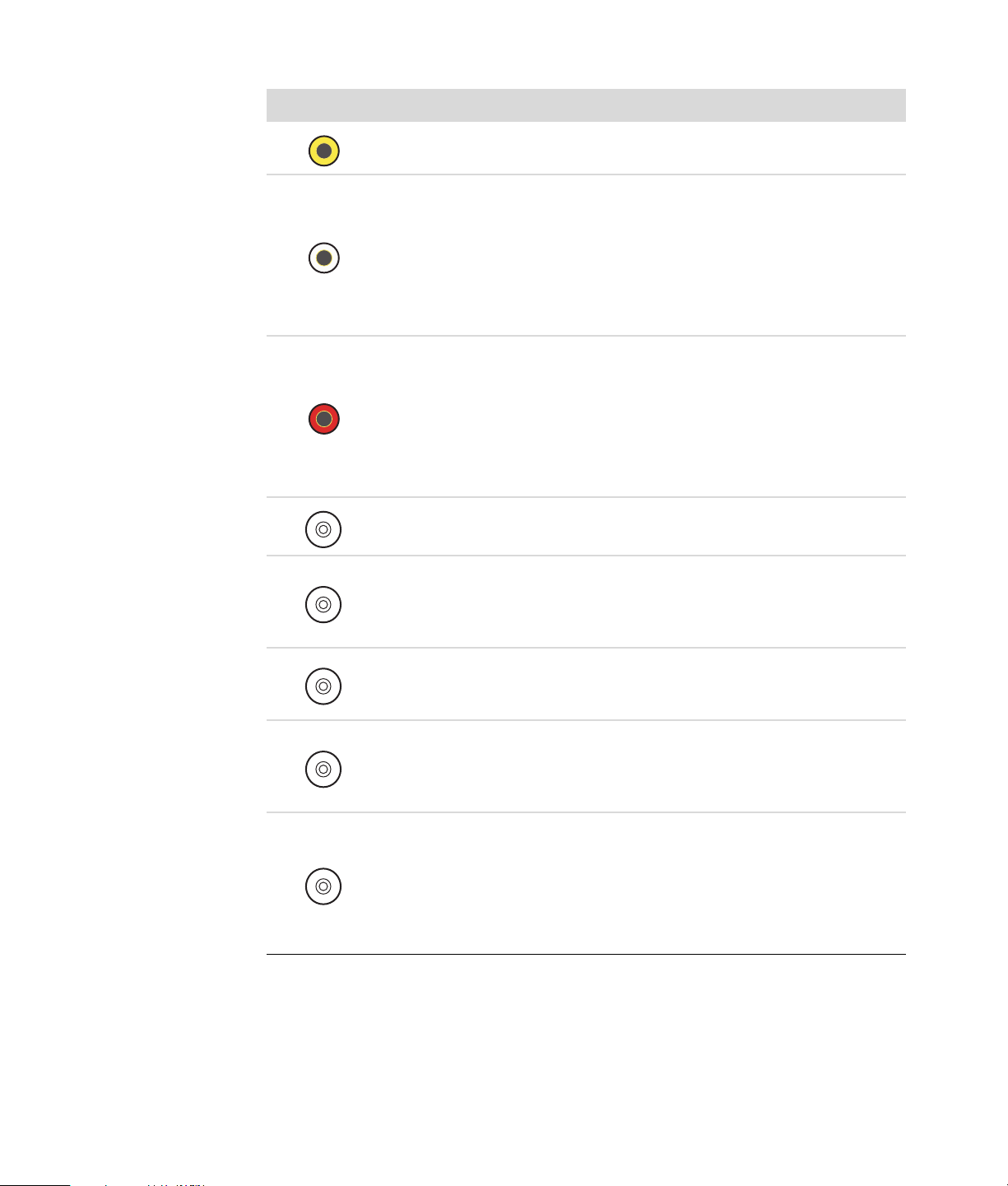
Connector Icon/Label Description and function (continued)
Printer (parallel) connector to connect a parallel
printer (select models only).
Universal Serial Bus (USB) 2.0 connector to connect
a mouse, keyboard, digital camera, or another
device with a USB connector.
Ethernet LAN connector is a network interface
adapter (also called a network interface card, or
NIC) that connects to an Ethernet (10BaseT) or Fast
Ethernet (100BaseT) network hub.
ETHERNET
Connect this adapter on the computer with your
local area network (LAN) hub or any broadband
connection.
The green LED indicates a valid connection.
Microphone In (Mic) (pink) to connect to a
microphone (also functions as a center/subwoofer
Line Out when a multichannel audio configuration is
activated).
Center
Rear
Side
S-Video
Audio Line Out (green) to connect front speakers.
Audio Line In (blue) connector to connect to an
analog audio device such as a CD player for input
into computer (also functions as rear Line Out when
a multichannel audio configuration is activated).
Line C/Sub (gold) connector to connect Center/
Subwoofer speakers in a multichannel audio
configuration.
Line Rear (black) connector to connect rear speakers
in a multichannel audio configuration.
Line Side (gray) connector to connect side speakers
in an eight-speaker system (7.1).
S-video In connector to connect from a set-top box
output connector.
Setting Up the Computer 5
Connector Icon/Label Description and function (continued)
Composite
Video
A/V In
Audio 1
L
A/V In
Audio 1
R
TV/Cable Ant
ATSC
Composite Video In connector (yellow) to connect to
a TV set-top box.
Primary left audio input from set-top box
connector (white).
NOTE: Audio can be recorded by using this Audio
In connector, which is connected to the
motherboard. Some computers include this primary
left audio input connector on the front of the
computer (select models only).
Primary right audio input from set-top box
connector (red).
NOTE: Audio can be recorded by using this Audio
In connector, which is connected to the
motherboard. Some computers include this primary
right audio input connector on the front of the
computer (select models only).
TV In (TV antenna or cable input from wall outlet
with no set-top box).
TV In connector for TV cable or antenna, which
receives ATSC channels (Advanced Television
System Committee), which are over-the-air digital
transmission channels.
6 Advanced Setup Guide (features vary by model)
CATV
NTSC
FM Ant
TV In connector for TV cable or antenna, which
receives CATV (Community Antenna Television) or
cable TV channels.
TV In connector for TV cable or antenna, which
receives NTSC channels (National Television System
Committee), which are over-the-air analog
transmission channels.
FM In (radio antenna input) connector, which
connects to the FM antenna cable.
Plug the FM radio antenna cable into the FM In port
on the back of the computer on the TV tuner card.
You may want to extend the ends of the cable to
improve your FM radio signal reception.
Connector Icon/Label Description and function (continued)
Modem (Line In RJ-11) (select models only).
Plug the modem cable (provided in the computer
box) into the computer modem connector on the
back of the computer. Plug the other end to the
telephone line wall jack connector.
Analog Video Out: S-video or composite video
Analog Video
connector (select models only), which connects
to a TV.
VGA/Monitor
HDMI
DVI
Digital Audio
Out
VGA/Monitor (blue) display output connector,
which connects to a VGA monitor. You may need to
use a VGA-to-DVI adapter to connect the display to
the computer.
HDMI display output connector, which connects to
an HDMI monitor or TV display. You may need to
use a HDMI-to-DVI adapter to connect the display to
the computer.
Digital video output connector, which connects to a
TV or monitor (select models only). You may need to
use a VGA-to-DVI or a HDMI-to-DVI adapter to
connect the display to the computer.
See the documentation that came with the
display device.
Digital audio input (white) connector, which
connects to a digital audio device with digital input
(such as a home audio receiver/amplifier) or digital
speakers (select models only).
Digital audio output (red) connects to a digital audio
device with digital output (select models only).
Digital Out (orange) connector, which connects to a
digital audio device with digital input (such as a
home audio receiver/amplifier) or digital speakers
(select models only).
Setting Up the Computer 7
Connecting a Digital Camera (Photo or Video)
The following instructions apply only to digital photo cameras and digital video cameras.
NOTE: When connecting an analog video camera to the computer, use the Video and
Audio In connectors on the front or back of the computer.
Refer to the documentation that came with your digital photo camera or digital video
camera.
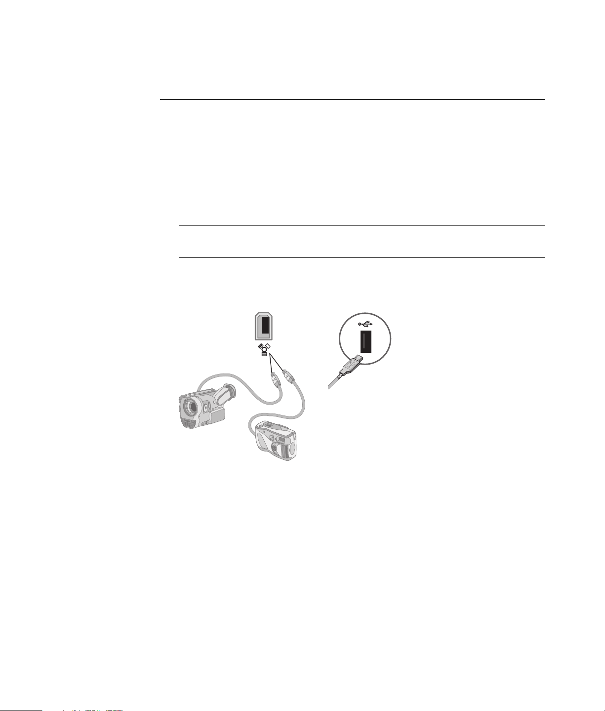
To connect a digital photo camera or a digital video camera:
®
1 Turn on the computer, and wait for the Microsoft
to start.
NOTE: If a Digital Video Device AutoPlay window appears when you connect the
camera, click Cancel.
2 Connect the 6-pin video camera transfer cable into the camera, and then into an open
port on the front or back of the computer. Most digital video cameras use either the
FireWire (IEEE 1394) port or the USB port.
Windows Vista® operating system
3 A Found New Hardware message appears. Wait 2 or 3 minutes for Windows Vista to
make the necessary settings for the new device. When installation is complete, a
message appears, indicating that the camera is ready to use.
8 Advanced Setup Guide (features vary by model)
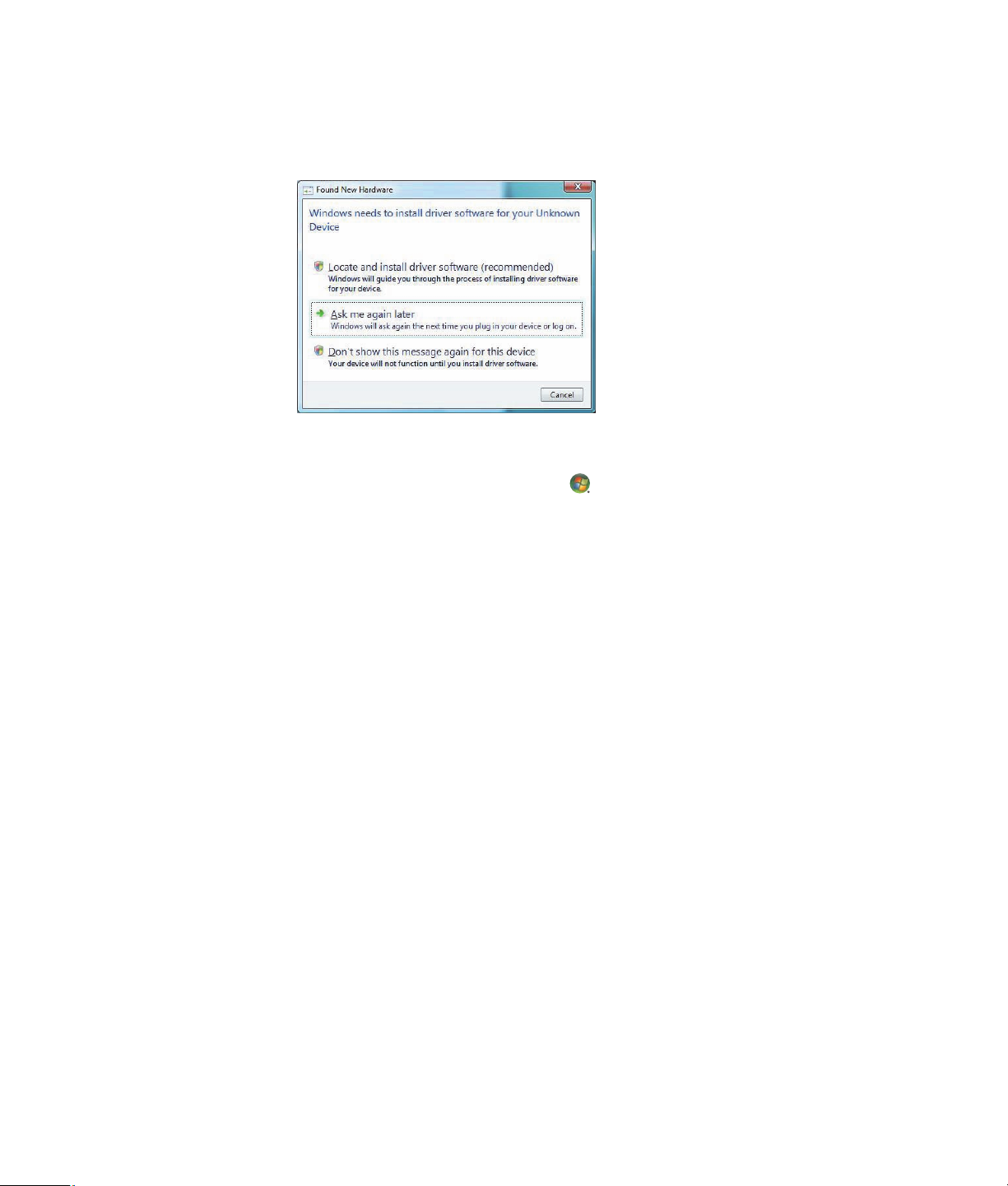
4 You may need to install driver software for your camera. If so, Windows displays a
message asking if you want to locate and install driver software. Insert the driver
software CD, click Locate and install driver software, and then follow any
onscreen instructions to install the software.
If the computer does not recognize the digital photo camera or the digital video camera:
1 Click the Windows Start Button
®
on the taskbar, and then click
Control Panel.
2 Click System and Maintenance, and then click System.
3 Click Device Manager.
4 Click the plus sign (+) next to the camera port. If the name of the camera appears, the
device is ready. If the name is not there, try the following:
Click Action, and then click Scan for hardware changes. Look in Device
Manager for a new addition under the port.
Unplug the video camera transfer cable from the computer, and plug it into a
different port. Look in Device Manager for a new addition under the port.
Setting Up the Computer 9
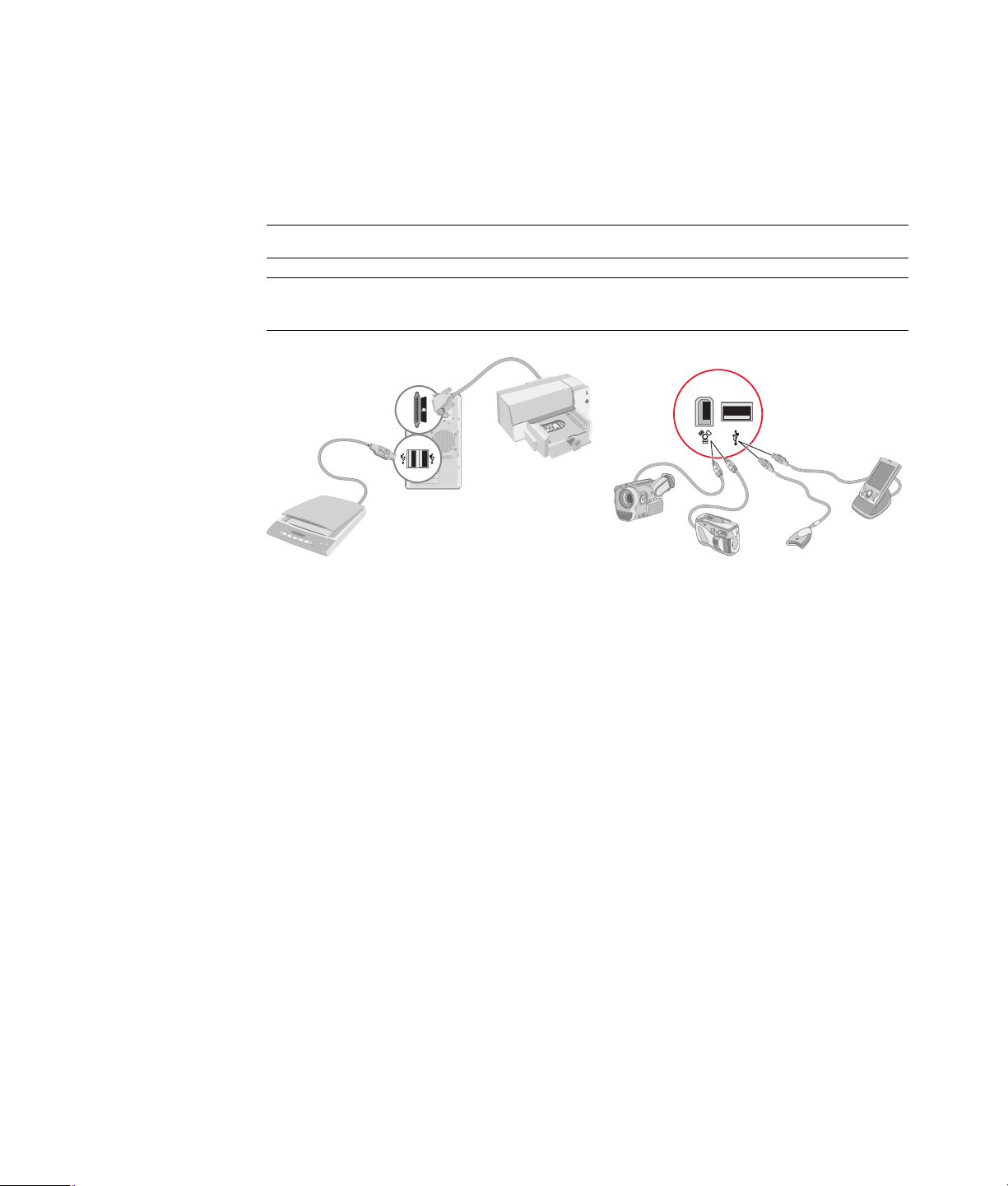
Connecting Other Devices
Other peripheral devices can be connected to the front or back of the computer by using
USB or FireWire (IEEE 1394) ports. These peripheral devices include printers, scanners,
video cameras, digital photo cameras, memory card readers, and PDAs (personal digital
assistants) or handheld computers. Refer to the documentation that came with your device.
NOTE: Some peripheral devices are not included with the computer.
NOTE: You must use a 6-pin (not a 4-pin) FireWire (IEEE 1394) cable with the 6-pin
FireWire (IEEE 1394) connector on the computer.
Storing Documentation and Recovery Discs
Store all computer user manuals and warranty information in an easy-to-find, safe location.
It is a good idea to store the system recovery discs with the documentation. This allows
easy access to all important computer documents and files.
10 Advanced Setup Guide (features vary by model)

Adjusting the Monitor
Adjusting the screen resolution by using Vista
To change the screen resolution by using Vista:
1 Right-click an empty area of the desktop, and then click Personalize.
2 Click Display Settings.
3 If necessary, select the monitor, and then adjust the screen resolution by using the
slider under Resolution.
4 Click Apply.
5 Click Yes, if it is present.
6 Click OK.
NOTE: You can connect more than one display device (CRT monitor, flat panel monitor,
TV, and so on) to the computer at a time (select models only). You can quickly change
which device displays the computer desktop by pressing Alt+F5. Each time you press
Alt+F5, the computer desktop appears on the next device. If pressing Alt+F5 does not
work, restart the computer and try again.
Adjusting the screen resolution by using the NVIDIA Control Panel
To change the screen resolution by using the NVIDIA Control Panel:
1 Right-click an empty area of the desktop, and then click NVIDIA Control Panel.
2 Select Standard or Advanced and then click OK.
3 Under Display, click Change resolution.
4 If necessary, select the display, and then adjust the screen resolution by using the
slider under Display resolution.
5 Click Apply, and then click Yes if you want to apply that resolution.
Or
Click No, and change the resolution by using the slider under Display resolution
again, click Apply and then click Yes.
Setting Up the Computer 11
Setting Up a Local Area Network
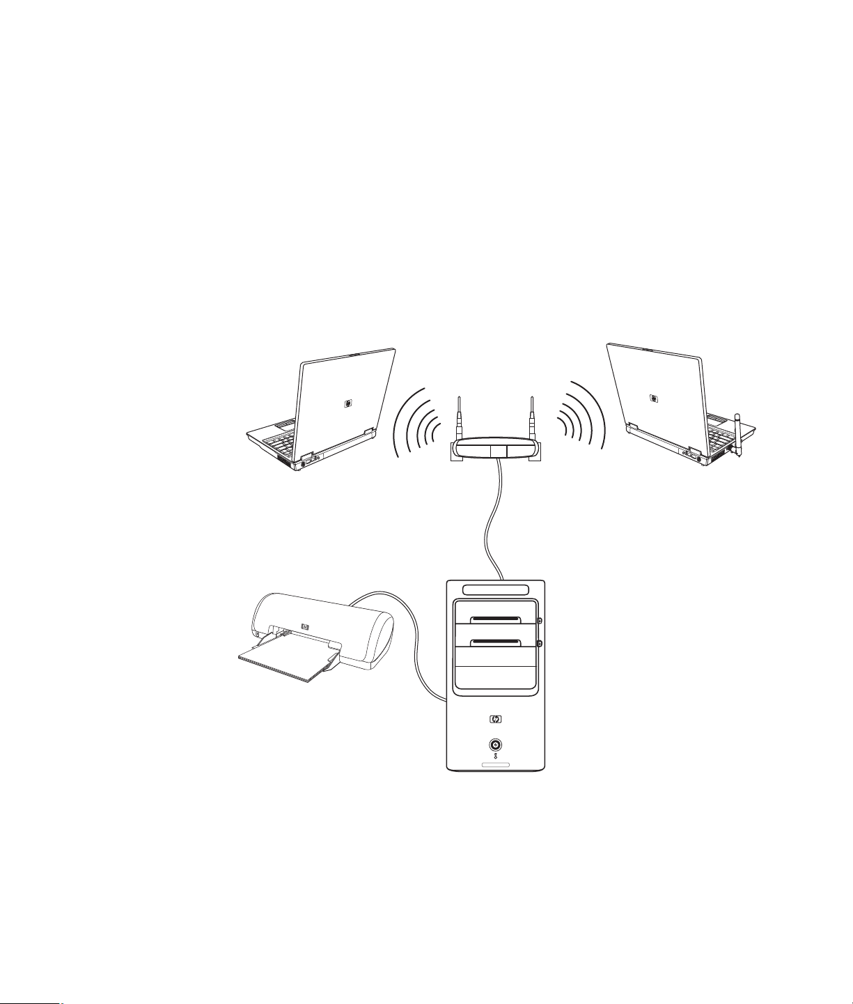
A home local area network (LAN) may consist of either a wired or a wireless network that
you can use to connect the computer to other devices on the network, including other
computers. The network components may include a hub or a switch, which can connect
multiple devices to the network, or a router, which can connect computers or a broadband
Internet connection to the network. This network connection also enables you to share data
and printers or other devices among your computers. The network connection to the
Internet is usually through a dial-up or cable modem.
A wired network uses Ethernet cables to connect the devices on the network. For example,
the Ethernet cable plugs into the computer network interface adapter and the router.
A wireless network uses radio waves to connect the devices on the network. For example,
both the computer and the router have an antenna and adapter that use the same
Wi-Fi industry standard: 802.11n, 802.11b, 802.11g, or 802.11a.
The preceding illustration shows a home LAN. The desktop computer has a wired
connection to a wireless router. The desktop computer also has a printer that it shares with
the other computers on the network. Each notebook computer has a wireless connection to
the network router.
12 Advanced Setup Guide (features vary by model)
Setting Up a Wired (Ethernet) Connection
The Ethernet connection, which may be called network interface adapter, Network
Interface Card, or NIC, provides a high-speed or broadband connection to an
Ethernet (10BaseT) or Fast Ethernet (100BaseT) network. After you connect this interface to
a network, such as a LAN, you can connect to the Internet through the network.
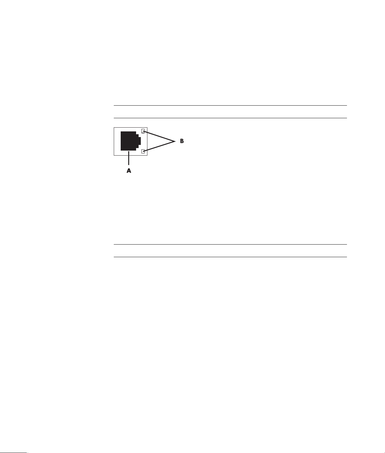
1 Connect an Ethernet cable to the Ethernet connector (A) on the back of the computer,
and to the network router or LAN device.
NOTE: Your computer may not come with an Ethernet connector.
A Ethernet connector (RJ-45 port)
B Ethernet indicator lights
2 With the computer turned on, check the indicator lights (B) next to the Ethernet
connector for the status:
ACTIVITY — Lit yellow during network data transfer activity
LINK — Lit green when there is a valid network connection
NOTE: Your Ethernet connector may have only one indicator light.
Integrated Wireless Devices
Wireless technology transfers data across radio waves instead of wires. Your computer
may be equipped with one or more of the following integrated wireless devices:
Wireless local area network (WLAN) devices connect the computer to
wireless local area networks (commonly referred to as wireless networks, wireless
LANs, or WLANs) in corporate offices, your home, and public areas such as airports
and restaurants. In a WLAN, each mobile wireless device communicates with a
wireless access point, which can be several meters away.
Computers with WLAN devices may support one or more of the four IEEE physical
layer industry standards: 802.11n, 802.11b, 802.11g, or 802.11a.
Bluetooth devices create a personal area network (PAN) to connect to other
Bluetooth-enabled devices such as computers, phones, printers, headsets, speakers,
and cameras. In a PAN, each device communicates directly with the other devices,
and the devices must be relatively close together—10 meters of each other.
Setting Up the Computer 13
Wireless wide area network (WWAN) devices provide access to information
anytime and anywhere that you have cellular (data) coverage. In a WWAN,
each mobile device communicates to a public carrier’s base station. Public carriers
install networks of base stations (similar to cell phone towers) throughout large
geographic areas, effectively providing coverage across entire states, or even entire
countries/regions.
For more information about wireless technology, go to:
http://www.hp.com/go/techcenter/wireless
Connecting the Wireless LAN Device
(Select models only)
You can connect the computer to an 802.11n (select models only), 802.11b or
802.11g wireless network by using the external antenna that was included with the
system. This device enables you to establish a wireless network using the computer as a
wireless access point, or you can use the computer as a wireless client (Station Mode) if
you already have a wireless network running.
You need an existing wireless LAN with an Internet connection (consult your Internet
Service Provider for further information). An external antenna is supplied with the system;
you must connect it to the 802.11 module to increase the range and sensitivity of
the radio.
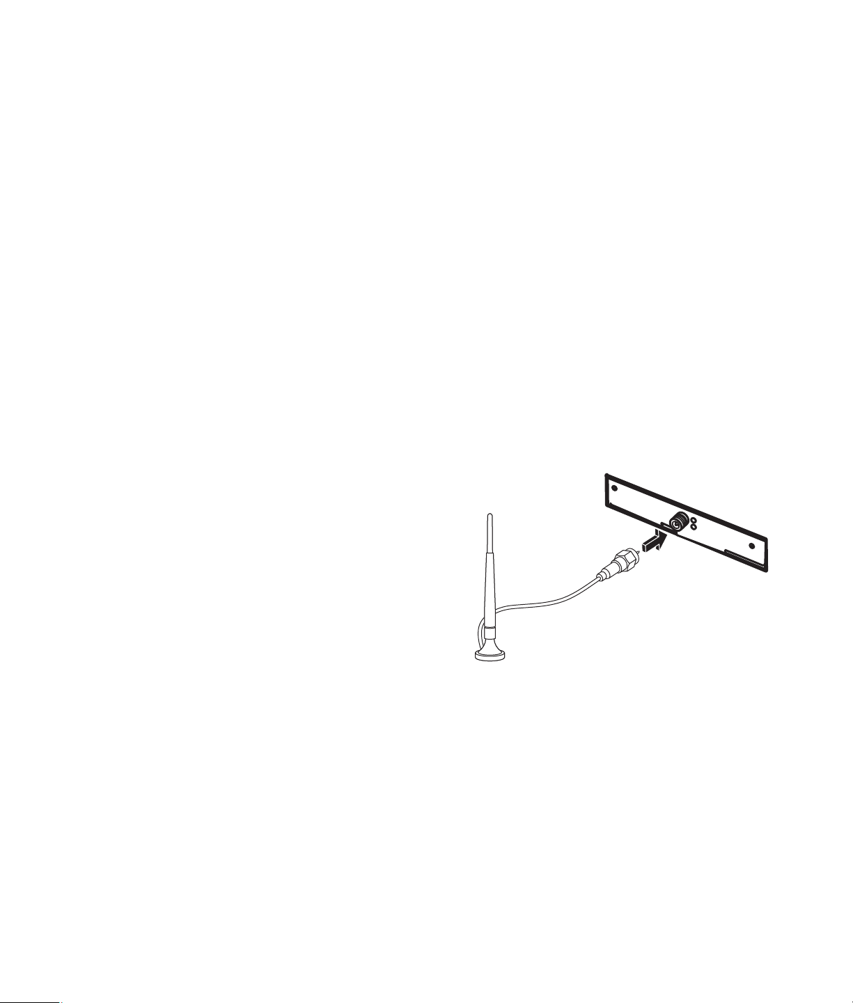
To connect the wireless LAN antenna:
1 Screw the wireless LAN antenna
cable into the wireless LAN
connector on the back of
the computer.
2 For the best wireless performance,
place the antenna on the computer
or in an elevated and open area.
14 Advanced Setup Guide (features vary by model)

Checking the wireless LAN device installation
To set up your wireless network, verify that the integrated WLAN device is installed on the
computer correctly:
1 Click the Windows Start Button on the taskbar.
2 Type Device Manager into the Start Search box, and then click Device Manager to
open the Device Manager window.
3 Click Network adapters. Your WLAN device should be listed here. The WLAN
device may include the term wireless, wireless LAN, or 802.11.
NOTE: If no WLAN device is listed, either the computer does not have an integrated
WLAN device, or the driver for the device is not properly installed.
4 Click the Windows Start Button on the taskbar.
5 Type Network and Sharing Center into the Start Search box, and then click Network
and Sharing Center to open the Network and Sharing Center window.
6 Click Connect to a network, and then follow onscreen instructions.
For more information about setting up a wireless network:
Click the Windows Start Button on the taskbar, click Help and Support,
and then type Setting up a wireless network into the Search Help box.
Go to: http://www.hp.com/go/techcenter/wireless (English only).
Go to: http://hp.com/support and search for wireless topics.
Using wireless security features
When you set up a home WLAN or access an existing public WLAN, always enable
security features to protect the network from unauthorized access. The most common
security levels are Wi-Fi Protected Access Personal (WPA-Personal) and Wired Equivalent
Privacy (WEP).
When setting up a network, HP recommends that you use one or more of the following
security measures:
Enable WPA-Personal or WEP security encryption on the router.
Change the default network name (SSID) and password.
Set up a firewall.
Set security on your Web browser.
For more information about setting up wireless security features, go to:
http://www.hp.com/go/techcenter/wireless
Setting Up the Computer 15

Connecting a Modem
For information on connecting to the Internet, see “Connecting to the Internet” in the
Getting Started guide.
16 Advanced Setup Guide (features vary by model)

Connecting Speakers or Microphone
Speakers are included with the monitor (select models only), or they are sold separately.
For details about connecting stereo speakers to the computer, see the setup poster.
If the computer has multichannel audio speaker capacity (select models only), you can
connect four channels for four-speaker output, or six channels for 5.1 speaker output.
Connect the speaker system to the computer, and then configure the audio software for
sound output.
Sound Connector Types
Your model may include one of three analog sound connector types on the back of
the computer:
Three connectors
Six connectors
Audio card
The connectors are 3.5 mm stereo mini-jacks that connect from the back of the computer to
speakers and microphones.
Your system may also have a separate Digital Out connector (select models only).
Connecting Speakers or Microphone 17

Software configuration is different for each connector type, as noted in the instructions.
NOTE:
Type 3 has three connectors.
Type 6 has six connectors.
Type S has audio card.
Sound connector Illustration Type
Three
connectors
Six
connectors
Audio card
connector
Your computer model may include
three sound connectors. You can
connect up to a 5.1 audio system to the
computer.
Your computer model may include six
sound connectors on the back of your
computer. You can connect up to a
7.1 audio system to the computer.
Your computer may include a audio
card. You can connect up to a
5.1 audio system (7.1 audio system for
select models) or digital speakers to the
audio card on the computer.
See the following
illustrations.
3
6
S
When installing cables, use the sound connectors that match your computer model, as
shown in the installation procedure steps.
18 Advanced Setup Guide (features vary by model)

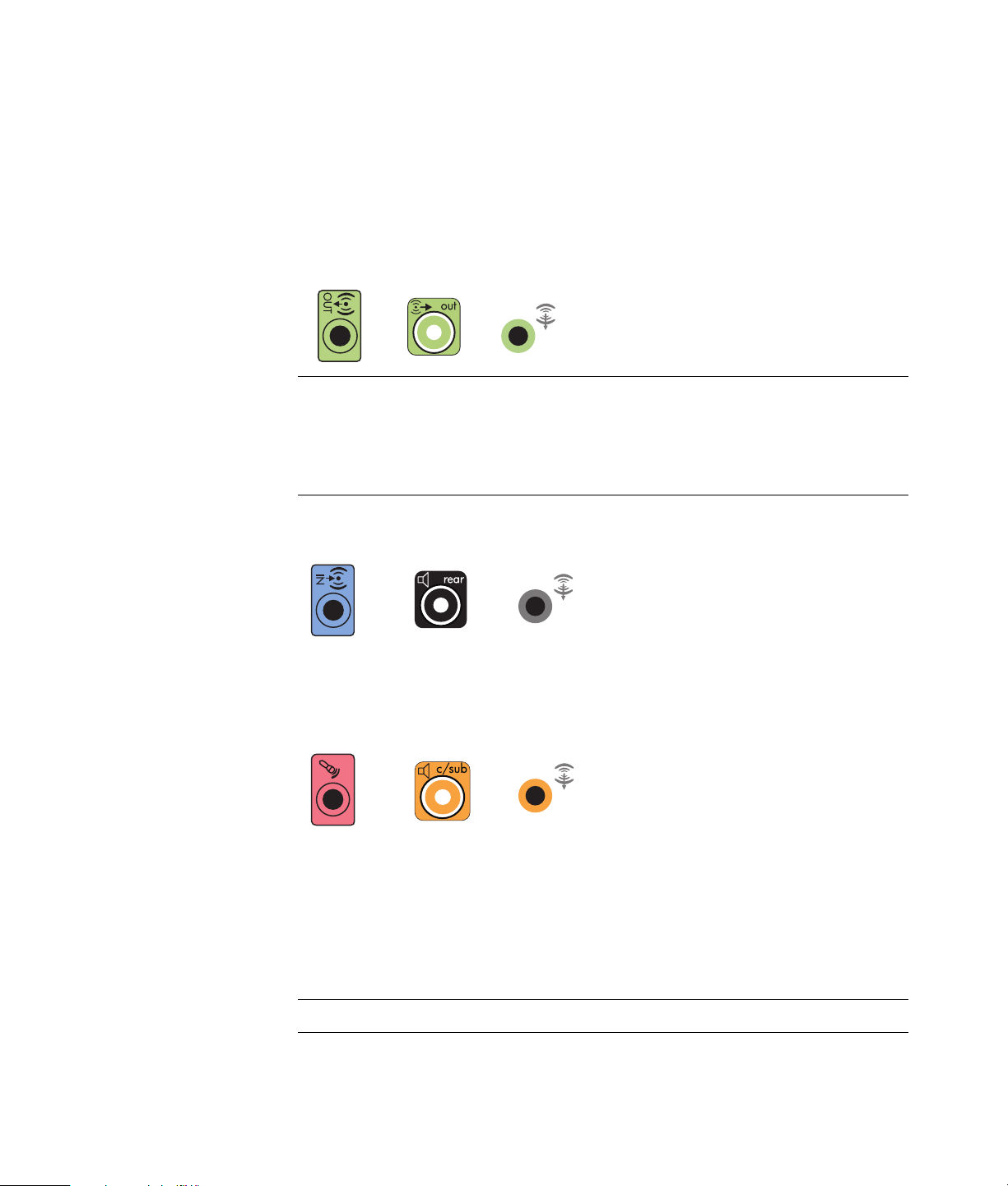
The following table shows the sound connectors on the back panel of computer systems.
Sound connector
Type 3 Type 6 Type S Description
Line Side (gray) connects to side left and right
analog speakers in an eight-speaker system (7.1).
Line C/Sub (gold) connects to front center/
subwoofer speakers in a multichannel audio
configuration.
Line Rear (black) connects to rear left and right
analog speakers in a multichannel audio
configuration.
Line Out (lime green) connects to front left and right
analog speakers.
Mic (pink) connects to a microphone.
(Type 3 also functions as center/subwoofer Line Out
when a multichannel audio configuration is enabled.)
Line In (light blue) connects to an analog audio
device such as a CD player for input into computer.
(Type 3 also functions as rear Line Out when a
multichannel audio configuration is enabled.)
Digital Audio Out or SPDIF Out (orange)
connects to a digital audio device with digital input
(such as a home audio receiver/amplifier) or to
digital speakers (select models only).
FlexiJack (pink) connects to analog Line In devices
or a microphone.
The FlexiJack supports two functions. You must select
either the microphone or the Line In function in the
Creative Console Launcher. See “Configuring the
FlexiJack connector” in the Getting Started guide.
Connecting Speakers or Microphone 19

Sound connector (continued)
Type 3 Type 6 Type S Description
FlexiJack (blue) connects to analog Line In devices
or a microphone.
The FlexiJack supports two functions. You must select
either the microphone or the Line In function in the
Creative Console Launcher. See “Configuring the
FlexiJack connector” in the Getting Started guide.
Optical In (optical SPDIF input) connects recording
devices such as a mini disc recorder, digital audio
tape recorder, or external hard disk recorder.
Optical Out (optical SPDIF output) connects
playback devices such as a mini disc player, digital
audio tape player, or DVD player.
NOTE:
Type 3 has three connectors.
Type 6 has six connectors.
Type S has audio card.
Connecting a Microphone
Your computer comes with one microphone connector in the back of the computer. Some
models have a second microphone connector in the front of the computer. Only one
microphone connector works at a time, and the back connector is ready to use unless you
have the multichannel audio speakers option. For computers with the multichannel audio
speakers option, the microphone connector in the front of the computer, if present, is ready
to use.
To use a microphone connected to the front of your computer (select models only), select
the working microphone. See “Selecting a microphone” in the Getting Started guide.
HP computers support many different audio options, sound connections, and speaker
configurations. You may set up your computer for two stereo speakers or for multichannel
audio speaker systems. Connect your speaker system to the computer, and then configure
the audio software for sound output. For more details about connecting stereo speakers to
the computer, see the setup poster.
20 Advanced Setup Guide (features vary by model)

This chapter describes the most typical options. Your system may have different
components.
Speakers are included with the monitor (select models only) or are sold separately.
NOTE: For additional information on connecting the speakers, refer to the setup poster
that came with the computer and the documentation that came with your speakers.
Speaker Configurations
You may set up your computer for the following supported configurations:
Name Speaker system See
2 (stereo) Left speaker, right speaker. “Connecting 2/2.1 (Two speakers and
a subwoofer) audio speakers.”
2.1 Left speaker, right speaker,
and a subwoofer.
4.1 Two front speakers, two
rear speakers, and a
subwoofer.
6/5.1 Two front speakers, two
rear speakers, a center
speaker, and a subwoofer.
8/7.1 Two front speakers, two
rear speakers, two side
speakers, a center
speaker, and a subwoofer
(select models only).
Home audio
system
Digital audio Digital speakers or digital
Multistreaming
audio
Home stereo or home
theater audio system with
passive speakers.
input connector on audio
system.
Two front speakers, two
rear speakers, two side
speakers, a center
speaker, and a subwoofer
(select models only).
“Connecting 2/2.1 (Two speakers and
a subwoofer) audio speakers.”
“Connecting 4.1 (Four speakers and a
subwoofer) audio speakers.”
“Connecting 5.1 (Five speakers and a
subwoofer) audio speakers.”
“Connecting 7.1 (Seven speakers and
a subwoofer) audio speakers.”
“Connecting your home stereo system
(optional).”
“Connecting digital audio.”
See “Configuring multistreaming
audio” in the Getting Started guide.
Connecting Speakers or Microphone 21

Speaker types
Speakers may be included with the monitor (select models only) or are sold separately.
Refer to the product documentation for your speakers.
Your computer supports only an active (powered) speaker system. An active speaker
system must have its own power cord. A home audio system does not require active
speakers, because the receiver provides amplification.
A stereo speaker set is a left-right, two-channel speaker system. A multichannel audio
speaker system has a left-right front and left-right rear channel, and it may include a
subwoofer and a center speaker. Side speakers are included in more advanced systems. A
subwoofer provides enhanced bass sounds.
“.1” indicates a subwoofer. For example, 7.1 channels refers to an eight-speaker mode
and uses two front speakers (left-right), two side speakers (left-right), two rear speakers
(left-right), a center speaker, and a subwoofer.
Connecting 2/2.1 (Two speakers and a subwoofer) audio speakers
To connect simple left/right stereo active speakers or two speakers and a subwoofer for
two-channel (2.1 speaker) output:
1 Turn off the computer.
2 Connect the speaker cable to the lime green Audio Line Out connector that matches
the back of your computer.
36S
NOTE:
Type 3 is three connectors.
Type 6 is six connectors.
Type S is sound card.
3 Connect the cable to the audio system. For 2.1 speakers that were shipped with your
computer (select models only), connect the Audio Line Out connector to the subwoofer.
4 Connect the left and right speakers to the subwoofer. Refer to the speaker
documentation.
5 Turn on the computer.
NOTE: Always turn on the computer before you turn on the speaker system.
6 Plug in the speaker system power.
7 Turn on the speaker system.
22 Advanced Setup Guide (features vary by model)

Step 8 is optional for a two-speaker setup.
8 After the speakers are connected to the computer, configure the audio software for
sound output for your computer model. See “Connecting Speakers or Microphone.”
Type 3: See “Configuring speakers with Realtek HD Audio Manager” in the
Getting Started guide.
Type 6: See “Configuring speakers with Realtek HD Audio Manager” in the
Getting Started guide.
Type S (audio card): See “Using the Creative Sound Blaster X-Fi or X-Fi Fatality
audio card” in the Getting Started guide.
The following diagram shows a typical 2.1 audio installation:
Connecting 4.1 (Four speakers and a subwoofer) audio speakers
To connect two front speakers, two rear speakers, and a subwoofer for four-channel
(4.1 speaker) output:
1 Turn off the computer.
2 Connect the front speaker cable to the lime green Audio Line Out connector that
matches the back of your computer.
36S
NOTE:
Type 3 is three connectors.
Type 6 is six connectors.
Type S is sound card.
Connecting Speakers or Microphone 23

3 Connect the rear speaker cable to the black connector that matches the back of
your computer.
36S
For type 3-connector systems, the blue Audio Line In connector functions as a Rear Line
Out when a multichannel audio configuration is activated.
4 Connect the cables to the audio system.
5 Connect the front and rear speakers to the subwoofer. Refer to the speaker
documentation.
6 Turn on the computer.
NOTE: Always turn on the computer before you turn on the speaker system.
7 Plug in the speaker system power.
8 Turn on the speaker system.
9 After the speakers are connected to the computer, configure the audio software for
sound output for your computer model. See “Configuring Speaker and Sound
Options” in the Getting Started guide.
Type 3: See “Configuring speakers with Realtek HD Audio Manager” in the
Getting Started guide.
Type 6: See “Configuring speakers with Realtek HD Audio Manager” in the
Getting Started guide.
Type S (audio card): See “Using the Creative Sound Blaster X-Fi or X-Fi Fatality
audio card” in the Getting Started guide.
The following diagram shows a typical 4.1 audio installation:
24 Advanced Setup Guide (features vary by model)
Connecting 5.1 (Five speakers and a subwoofer) audio speakers
To connect two front speakers, two rear speakers, a center speaker, and a subwoofer for
six-channel (5.1 speaker) output:
1 Turn off the computer.
2 Connect the front speaker cable to the lime green Audio Line Out connector that
matches the back of your computer.
36S
NOTE:
Type 3 is three connectors.
Type 6 is six connectors.
Type S is sound card.
3 Connect the rear speaker cable to the black connector that matches the back of
your computer.
36S
For type 3-connector systems, the blue Audio Line In connector functions as a Rear Line
Out when a multichannel audio configuration is activated.
4 Connect the center/subwoofer speaker cable to the gold (or pink Mic) connector that
matches the back of your computer.
36S
For type 3-connector systems, the pink Mic connector functions as a center/subwoofer
speaker Line Out when a multichannel audio configuration is activated.
5 Connect the cables to the audio system.
6 Connect the front, rear, and center speakers to the subwoofer. Refer to the speaker
documentation.
7 Turn on the computer.
NOTE: Always turn on the computer before you turn on the speaker system.
Connecting Speakers or Microphone 25

8 Plug in the speaker system power.
9 Turn on the speaker system.
10 After the speakers are connected to the computer, configure the audio software for
sound output for your computer model. See “Configuring Speaker and Sound
Options” in the Getting Started guide.
Type 3: See “Configuring speakers with Realtek HD Audio Manager” in the
Getting Started guide.
Type 6: See “Configuring speakers with Realtek HD Audio Manager” in the
Getting Started guide.
Type 6 — multistreaming: See “Configuring multistreaming audio” in the Getting
Started guide.
Type S (audio card): See “Using the Creative Sound Blaster X-Fi or X-Fi Fatality
audio card” in the Getting Started guide.
The following diagram shows a typical 5.1 audio installation:
Connecting 7.1 (Seven speakers and a subwoofer) audio speakers
(Select models only)
To connect two front speakers, two side speakers, two rear speakers, a center speaker,
and a subwoofer for eight-channel (7.1 speaker) output:
1 Turn off the computer.
2 Connect the front speaker cable to the lime green Audio Line Out connector on the
back of your computer.
26 Advanced Setup Guide (features vary by model)

3 Connect the rear speaker cable to the black Audio Line Rear connector on the back of
your computer.
4 For type 6 connectors only, connect the side speaker cable to the gray Audio Line Side
connector on the back of your computer.
5 Connect the center speaker and subwoofer speaker cable to the gold Audio
Line C/ Sub connector on the back of your computer.
6 Connect the cables to the audio system.
7 Connect the front, rear, side, and center speakers to the subwoofer. Refer to the
speaker documentation.
8 Turn on the computer.
NOTE: Always turn on the computer before the speaker system.
9 Connect the speaker system to the power.
10 Turn on the speaker system.
11 After the speakers are connected to the computer, configure the audio software for
sound output for your computer model.
Type 6 — multistreaming: See “Configuring multistreaming audio” in the Getting
Started guide.
Connecting Speakers or Microphone 27

The following diagram shows a typical 7.1 audio installation.
Color Description
1 Lime green Front audio input
2 Black Rear audio input
3 Orange Center/subwoofer audio input
4 Gray Side audio input (not shown)
28 Advanced Setup Guide (features vary by model)

Connecting your home stereo system (optional)
Most home receivers/amplifiers have RCA-type input connectors. You must connect
Y adapter cables between your computer and your receiver/amplifier. Y adapter cables
have one 3.5 mm stereo mini-jack on one end, and two RCA connectors on the other.
These cables are purchased separately.
The number of Y adapter cables that you need to connect to your home stereo system
depends on the number of speakers that you install:
2/2.1 speaker system: One Y adapter cable
4/4.1 speaker system: Two Y adapter cables
6/5.1 speaker system: Three Y adapter cables
8/7.1 speaker system: Four Y adapter cables
Connecting a home stereo system to a computer requires audio cables that are long
enough to reach from the computer to the stereo. You also must purchase Y adapter or
mini-extension cables.
NOTE: Y adapter and mini-extension cables are purchased separately.
Connecting Speakers or Microphone 29

2.1 home stereo installation
A
The following diagram shows a typical two-channel (2.1 speaker) installation that uses
passive stereo speakers and plugs into a home stereo standard left and right input.
This is only a suggested configuration. Your system may be different.
B
C
ECDE
Computer to 2.1 multichannel audio system connection
A Computer back-panel connectors (type 3, type 6, or sound card)
B Y adapter cables
C Receiver/amplifier (audio input jacks)
D Subwoofer
E Front speakers (left and right)
30 Advanced Setup Guide (features vary by model)

5.1 home audio installation
The following diagram shows a typical advanced home theater audio six-channel
(6/5.1 speaker) installation that requires multichannel inputs on a receiver/amplifier.
This is only a suggested configuration. Your system may be different.
A
B
C
DEFGC
Computer to 5.1 multichannel audio system connection
A Computer back-panel connectors (type 3, type 6, or sound card)
B Y adapter cables
C Receiver/amplifier (audio input jacks)
D Subwoofer
E Center speaker
F Front speakers (left and right)
G Rear speakers (left and right)
5.1 home audio installation procedure
To connect a six-channel (5.1 speaker) home audio system to the computer:
1 Turn off the computer.
2 Turn off the receiver/amplifier.
Connecting Speakers or Microphone 31

3 Connect the front stereo mini-jack end of a Y adapter cable into the lime green Audio
Line Out connector that matches the back of your computer.
36S
NOTE:
Type 3 is three connectors.
Type 6 is six connectors.
Type S is sound card.
NOTE: Receiver/amplifier input connectors may be labeled Surround, 5.1 Channel
inputs, 6 Channel inputs, CD, DVD, or DVD In.
Connect the left and right ends of the Y adapter cable into the front left (L) and right (R)
inputs on the back of the receiver/amplifier.
4 If you have rear speakers, connect the rear stereo mini-jack end of a Y adapter cable
into the Audio Line In (blue) or the Rear Speaker Out (black) connector that matches
the back of your computer.
36S
Connect the left and right ends of the Y adapter cable into the rear left (L) and
right (R) inputs on the back of the receiver/amplifier.
5 If you have a center/subwoofer speaker, connect the stereo mini-jack of a Y adapter
cable into the microphone (pink) connector or the center speaker/subwoofer (gold)
connector that matches the back of your computer.
36S
Connect the left and right ends of the Y adapter cable into the center/subwoofer
inputs on the back of the receiver/amplifier (6/5.1 or higher-channel system).
Plug the Y adapter cable into the subwoofer connector on the back of the receiver
even if a subwoofer is not used.
6 Turn on the receiver/amplifier.
7 Select the receiver/amplifier input that the Y adapter cables are plugged into.
8 Turn on the computer.
32 Advanced Setup Guide (features vary by model)

9 After the audio system is connected to the computer, configure the audio software for
sound output for your computer model. See “Connecting Speakers or Microphone.”
Type 3: See “Configuring speakers with Realtek HD Audio Manager” in the
Getting Started guide.
Type 6: See “Configuring speakers with Realtek HD Audio Manager” in the
Getting Started guide.
Type S (audio card): See “Using the Creative Sound Blaster X-Fi or X-Fi Fatality
audio card” in the Getting Started guide.
7.1 home audio installation
The following diagram shows a typical advanced home theater system with an
eight-channel 8/7.1 speaker installation that requires multichannel inputs on a
receiver/amplifier.
This is only a suggested configuration. Your system may be different.
A
B
C
DEFGC
Computer to 7.1 multichannel audio system connection
A Computer back-panel connectors (type 3, type 6, or type S)
B Y adapter cables
C Receiver/amplifier (audio input jacks)
D Subwoofer
E Center speaker
F Front speakers (left and right)
G Rear speakers (left and right)
Connecting Speakers or Microphone 33

7.1 home audio installation procedure
To connect an eight-channel (7.1 speaker) home audio system to the computer:
1 Turn off the computer.
2 Turn off the receiver/amplifier.
3 Connect the front stereo mini-jack end of a Y adapter cable into the lime green Audio
Line Out connector on the back of your computer.
36S
NOTE:
Type 3 has three connectors.
Type 6 has six connectors.
Type S has audio card.
NOTE: Receiver/amplifier input connectors may be labeled Surround, 7.1 Channel
inputs, 6 Channel inputs, CD, DVD, or DVD In.
Connect the left and right ends of the Y adapter cable into the front left (L) and right (R)
inputs on the back of the receiver/amplifier.
4 If you have rear speakers, connect the rear stereo mini-jack end of a Y adapter cable
into the Audio Line In (light blue) or the Rear Speaker Out (black) connector on the
back of your computer.
36 S
Connect the left and right ends of the Y adapter cable into the rear left (L) and right (R)
inputs on the back of the receiver/amplifier.
34 Advanced Setup Guide (features vary by model)

5 If you have a center/subwoofer speaker, connect the stereo mini-jack of a Y adapter
cable into the microphone (pink) connector or the center speaker/subwoofer (gold)
connector on the back of your computer.
36S
Connect the left and right ends of the Y adapter cable into the center/subwoofer
inputs on the back of the receiver/amplifier (8/7.1 or higher-channel system).
Connect the Y adapter cable to the subwoofer connector on the back of the receiver,
even if you are not using a subwoofer.
6 Turn on the receiver/amplifier.
7 Select the receiver/amplifier input to which the Y adapter cables are connected.
8 Turn on the computer.
9 After the audio system is connected to the computer, configure the audio software for
sound output for your computer model. See “Configuring Speaker and Sound
Options” in the Getting Started guide.
Type 3: See “Configuring speakers with Realtek HD Audio Manager” in the
Getting Started guide.
Type 6: See “Configuring speakers with Realtek HD Audio Manager” in the
Getting Started guide.
Type S (audio card): See “Using the Creative Sound Blaster X-Fi or X-Fi Fatality
audio card” in the Getting Started guide.
Connecting digital audio
(Select models only)
If you have a audio card and you are connecting your home stereo AV receiver via digital
out, connect the 3.5 mm stereo plug to the Digital Audio Out connector on the audio card.
Connect the red RCA stereo plug on the 3.5 mm Y adapter cable to the AV receiver’s
digital input connector on the AV receiver. If the red RCA stereo plug does not work, try the
white stereo plug. Only one of the connectors is needed.
Connecting Speakers or Microphone 35

To connect digital audio, your computer must include a Digital Audio Out connector on
either the audio card or the back panel. You must connect multichannel speaker outputs if
you connect the digital output.
To connect digital audio speakers:
1 Turn off the computer.
2 Connect the orange Digital Audio Out connector on the back panel of
your computer to the digital input (S/PDIF) on the digital speakers or a
digital audio system.
3 Turn on the computer.
NOTE: Always turn on the computer before the speaker system.
4 Connect the speaker system to the power.
5 Turn on the speaker system.
6 After the speakers are connected to the computer, configure the audio software for
sound output for your computer model. See “Configuring Speaker and Sound
Options” in the Getting Started guide.
Audio card with digital output and type 3 connectors: See “Configuring speakers
with Realtek HD Audio Manager” in the Getting Started guide. Follow the
instructions to enable digital audio output.
Audio card with digital output and type 6 connectors: See “Configuring speakers
with Realtek HD Audio Manager” in the Getting Started guide. By default, digital
audio output is already enabled.
Audio card: See “Using the Creative Sound Blaster X-Fi or X-Fi Fatality audio
card” in the Getting Started guide. Follow the instructions to enable digital audio
output.
36 Advanced Setup Guide (features vary by model)

Connecting Speakers Using the Creative Sound Blaster X-Fi Sound Card
This section provides an overview of connecting to the Creative Sound Blaster X-Fi
sound card.
NOTE: For additional information on connecting the speakers, refer to the documentation
that came with your speakers.
Connecting the speakers
Connector Description
AD-Link for AD_Link X-Fi I/O Console (the X-Fi console is sold separately)
Line Out_3 (orange or yellow)
5.1 audio setup: Front center, subwoofer
6.1 audio setup: Front center, subwoofer, and rear center
7.1 audio setup: Front center, subwoofer, and side left
Line Out_2 (black)
4.1, 5.1, 6.1 audio setup: Rear left and right
7.1 audio setup: Rear left, rear right, and side right
Line Out_1 (lime green)
2/2.1 audio setup: Front left and right
FlexiJack (white) for Line In, Microphone, Digital In/Out
The FlexiJack supports three functions. You must select the function in the
Creative Console Launcher. See “Connecting the FlexiJack connector.”
Connecting Speakers or Microphone 37

To connect the X-Fi sound card to your speakers:
1 Use the audio connection table to connect your audio system to the sound card.
2 Turn on the computer.
3 Plug in and turn on the speaker system power.
After connecting the speaker system to the sound card, follow the steps in “Configuring the
FlexiJack connector” in the Getting Started guide to configure the speaker settings in the
Creative Sound Blaster X-Fi software.
Connecting the FlexiJack connector
The FlexiJack connector performs three functions:
Digital Input/Output
Line In
Microphone
You must select the function in the Creative Console Launcher.
NOTE: If you are using the FlexiJack as your Digital In connection and you want to
connect digital speakers as your output device, you will need a special connector from
Creative.
38 Advanced Setup Guide (features vary by model)

Connecting the Television Signal and
This section describes how to connect the computer to the television
and which cables to use.
NOTE: Some graphic cards have a DVI connector and a
DVI-to-VGA converter included in the box (select models only). If
the monitor has a VGA connector but no DVI connector, use the
DVI-to-VGA converter to connect to the computer: Connect the
DVI-to-VGA converter to the DVI connector on the computer
graphic card, and then connect the VGA cable to the converter
and to the monitor.
Using TV Cables
The computer includes video and audio cables to connect the television signals.
Use the video and audio cables to connect:
Video Cables
Video out from the computer to the TV.
TV signal source video in to the computer.
Audio out from the computer to the TV.
TV signal source audio in to the computer.
NOTE: The location and number of connectors may vary by model.
Connecting the Television Signal and Video Cables 39

Audio and Video Cables and Adapters
The following table shows the cable and adapter types that may be required to connect the computer to the
television system.
NOTE: The number and type of cables required to connect the computer may vary by model. Some cables are
included for select models only.
Cable Name Description
DVI-to-VGA adapter Connects a DVI monitor to a VGA
connector on the computer or connects a
VGA monitor to a DVI connector on the
back of the computer.
DVI-to-HDMI cable or adapter Connects a DVI monitor to an HDMI
connector on the computer or connects an
HDMI monitor to a DVI connector on the
back of the computer. This allows the
graphic card driver to transfer HDMI signals
to a monitor or a TV display.
Composite video cable RCA yellow end. Plugs into an RCA
connector such as Composite Video Out or
TV Source In.
S-video cable Y/C, 4-pin. Plugs into an S-video connector
such as S-video Video Out or TV Source In.
Delivers a sharper image than composite
video cable by providing separate color
and black-and-white image signals.
Analog video cable/adapter
(select models only)
DVI-I or DVI-D cable Digital Video Out. Plug into a DVI-I or DVI-D
Used with analog video output connector.
Provides S-video and composite video
output.
input of an HDTV-capable TV or monitor.
40 Advanced Setup Guide (features vary by model)

Cable Name Description (continued)
TV coaxial cable Plugs into a TV signal source input
connector from cable set-top boxes or
antennas.
Remote Infrared (IR) cable
(Infrared transmitter)
Splitter Connects one signal source to two RF inputs
RCA stereo RCA red and white ends. Connects TV
You may need to purchase extra cables separately. Your computer may not include all the cables you need for the
computer setup, and the cables included may vary by model.
For example, if the TV has an S-video input connector, you may want to use an S-video cable to connect the TV-out
on the computer to the TV.
Controls TV signal source from set-top box.
on the computer.
signal source Audio In and Audio Out
connectors to TV.
Connecting the TV Signal Source
Connect the signal source for the TV by using the TV In coaxial connector or the S-video or
composite video In connector.
NOTE: The location and number of connectors may vary by model.
1 Plug the connector of a coaxial cable from the TV cable into the TV/Cable Ant
connector on the back of the computer, and then turn the connector to tighten it.
Or
Plug a cable into the S-video or composite video In connector on the back of the
computer; use an S-video cable (not provided) or the composite video cable. Plug the
other end of the cable into the set-top box or other device that is providing the signal
source for the TV.
2 If you are using a set-top box with S-video or composite video output, plug audio
cables (not provided) from the set-top box into the Audio In right (red) connector and
the Audio In left (white) connector on the back of the computer.
If you are using a set-top box, connect the Remote Emitter cable. See “Connecting the
Remote Sensor.”
Connecting the Television Signal and Video Cables 41

Connecting a dual tuner
(Select models only)
NOTE: The Television (Electronic) Program Guide is not available in all countries/regions.
The computer records television programs and enables you to control the television
channels. The computer supports two tuner configurations:
TV tuner Description Requirements
Single-tuner TV
source
Dual-tuner TV
source
Watch or record only one
program in the NTSC
or PAL format.
Watch a show on one
channel while Windows
Media Center records
another show on a different
channel. You can also
record two different
programs at the same time.
If you are using a TV antenna or
standard cable connector, the
signal is routed to a single tuner.
If you are using a TV antenna or
standard cable connector, the
signal is routed to both tuners
internally.
If you are using a cable or
satellite set-top box, you must
connect a second set of inputs.
Otherwise, connect a second
set-top box to the second set of
back-panel connectors.
TV sources must be of the same
type: either cable TV, digital
cable TV, satellite TV, or
antenna.
TV sources must also have the
same, identical channel lineups;
for example, if you are using
two satellite TV sources, they
must provide exactly the same
channels.
42 Advanced Setup Guide (features vary by model)
All TV viewing and scheduling is
provided through the Television
(Electronic) Program Guide in
Windows Media Center, so both
TV sources must have identical
Television Program Guides.

Connecting the Remote Sensor
The remote sensor is a small device that connects to the computer and enables the remote
control to work with the Windows Media Center program.
1 If you have a cable TV set-top box, a satellite set-top box, or another set-top box that
controls the TV signal, connect the remote control sensor cable (emitter) (A) to
connector (1) on the back of the remote sensor; otherwise, skip to step 3. If you have
a second set-top box, you can also use connector (2).
2 Remove the paper from the backing tape on the end of the cable (B), and then press
the end of the cable over the remote infrared (IR) receiver window on the cable TV
set-top box (C). To locate the remote IR receiver window on the cable TV set-top box,
use a flashlight to shine through the plastic on the front of most devices.
3 Plug the remote control sensor cable into a USB connector (D) on the back of the
computer.
4 Place the remote sensor so that you can easily point at it with the remote control. (An
ideal spot would be on top of the monitor or desk.)
Connecting the Television Signal and Video Cables 43

Connecting the TV Signal Source When You Have an Existing Setup
This section describes how to connect the computer to an existing setup for the TV
signal source.
Wall to VCR to TV, using coaxial cable
1 Disconnect the coaxial cable from the input to the VCR, and connect it to the input of a
coaxial cable signal splitter (not included; available at electronics stores).
2 Connect two coaxial cables to the splitter outputs.
3 Connect one of these cables to the input of the VCR, and the other cable to the TV
connector on the back of the computer.
Existing setup Setting up the computer with a splitter
44 Advanced Setup Guide (features vary by model)
A Wall
B Cable outlet
C Coaxial cable
D VCR In
E VCR Out
F TV In
G Splitter In
H Splitter Out
J TV In on back of
computer

Wall to cable TV set-top box or satellite box to VCR to TV, using coaxial cable
1 Disconnect the coaxial cable from the input to the VCR, and connect it to the input of a
coaxial cable signal splitter (not included; available at electronics stores).
2 Connect two coaxial cables to the splitter outputs.
3 Connect one of these cables to the input of the VCR, and the other cable to the TV
connector on the back of the computer.
4 Connect the remote control sensor cable (emitter), and position it on the set-top box or
satellite box. This enables the computer to change the channel on the box. See
“Connecting the Remote Sensor.”
Setting up the computer with a splitterExisting setup
A Wall
B Cable outlet
C Coaxial cable
D Set-top box/Satellite In
E Set-top box/Satellite Out
F VCR In
G VCR Out
H TV In
J Splitter In
K Splitter Out
L TV In on back of computer
M Remote control sensor cable
N Remote control sensor
Connecting the Television Signal and Video Cables 45

Wall to cable TV set-top box or satellite box to VCR and TV, using S-video cable or composite video cable between the box and the VCR or TV
1 Do not detach any cables from the existing setup.
2 Connect an additional cable by doing one of the following:
Connect one end of an S-video cable (not included) to a second output on the
set-top box or satellite box. Connect the other end to the S-video In connector on
the back of the computer.
Or
Connect one end of a composite video cable to a second output on the set-top box
or satellite box. Connect the other end to the S-video-to-composite video adapter
cable, and then connect the adapter to the S-video In connector on the back of the
computer.
3 If you are using a composite video or S-video cable, you must also connect audio
cables (not included) from the satellite box or set-top box to the Audio In right (red)
and Audio In left (white) connectors on the back of the computer.
4 Connect the remote control sensor cable (emitter), and position it on the set-top box or
satellite box. This enables the computer to change the channel on the box. See
“Connecting the Remote Sensor.”
46 Advanced Setup Guide (features vary by model)

With a computerExisting setup
A Wall
B Cable outlet
C Set-top box/Satellite In
D Set-top box/Satellite Out
E S-video or composite
cable
F VCR In
G VCR Out
H TV In
J Add an S-video or
composite cable with
adapter
K S-video In on back of
computer
L Remote control sensor
cable
M Remote control sensor
N Set-top box/second
output
O R-Audio
P L-Audio
Connecting the Television Signal and Video Cables 47

Using a TV as a Monitor
(Select models only)
Your computer may have TV-out capability, that is, video output connectors, such as
DVI-out, Component-out, and S-video-out connectors. If so, you can connect a TV to one of
the output connector sets, and then view the computer desktop image, watch DVD movies,
or play games on the TV screen. TV-out connectors are an optional feature.
Cables for connecting the computer to a TV
To connect the computer to a TV, you need a video cable and an audio cable. The type of
video cable that you need depends on the connection jacks on the TV:
If the TV has an S-video input connector, you need an S-video cable.
If the TV has a composite video connector, you need a composite video cable.
Depending on the jacks on the back of the computer, you may also need an S-video
adapter cable.
Connecting the computer to a TV
1 Turn off the computer.
2 Connect the TV cable by doing one of the following, depending on the connection
connectors on the TV.
NOTE: There may be two S-video connectors on the back of the computer: S-video
Out on the video card (select models only), and S-video In on the TV tuner card.
If the TV has an S-video connector, connect an S-video cable (A) (not included)
from the S-video In connector on the TV to the S-video Out connector (B) on the
back of the computer (select models only).
If the TV has a composite video input connector, and the computer has a
composite video output connector, connect a composite video cable (C) to the
Video In connector on the TV and to the composite video out connector (D) on the
back of the computer (select models only).
48 Advanced Setup Guide (features vary by model)

3 To have sound come from the TV instead of from the computer, plug an audio cable
into the audio input connector (Audio Line In) on the TV, and plug the other end of the
audio cable into the audio output connector (Audio Line Out) on the back of the
computer.
4 Turn on the TV, and then select the TV In video source. For more information, refer to
the documentation for the TV set.
5 Turn on the computer. Enable the computer desktop for the TV. For more information,
see “Viewing the computer desktop on a TV screen.”
Viewing the computer desktop on a TV screen
The type of video card on the computer determines how the computer selects the TV-out
option.
When you want to disconnect the TV from the computer, you may need to disable the
TV-out option to return the computer desktop to its original resolution.
To enable the TV-out option:
1 Right-click an empty area of the desktop, and then click Personalize.
2 Click Display Settings.
3 If necessary, select the monitor or TV.
4 Click the Advanced button.
5 Click the tab for the video card. (The tab may be labeled Displays, ATI Displays,
Ge Force xxx, nView, or Devices.)
6 Choose the TV option, and then follow the onscreen instructions.
Adjusting the screen resolution
To change the screen resolution:
1 Right-click an empty area of the desktop, and then click Personalize.
2 Click Display Settings.
3 If necessary, select the monitor, and then adjust the screen resolution.
4 Click Apply.
5 Click Yes, if it is present.
6 Click OK.
Connecting more than one display
You can connect more than one display device (CRT monitor, flat panel monitor, TV, and so
on) to the computer at a time (select models only). You can quickly change which device
displays the computer desktop by pressing Alt+F5. Each time that you press Alt+F5, the
computer desktop appears on the next device. If pressing Alt+F5 does not work, restart the
computer and try again.
Connecting the Television Signal and Video Cables 49

Using the Windows Media Center Setup for Optional Setup of the TV Display
If the TV connects to the computer with a composite or S-video connection, the Windows
Media Center setup wizard cannot automatically adjust the settings for the display. This
automatic adjustment is available only during the Optional Setup, within the “Optimize
how Windows Media Center looks on your display” step.
The following procedure describes what to do within the Windows Media Center setup,
and how to use the Windows Desktop Properties window to adjust the settings for the TV
display:
NOTE: The type of video card on the computer determines how the computer selects the
TV-out option. Some options and menus in this procedure may be different for the
computer.
1 Press the Windows Media Center Start button on the remote control. Or, with the
mouse, click the Windows Start Button on the taskbar, and then click
Windows Media Center.
2 From the Tasks menu, click settings, and then click TV.
3 Click Configure Your TV or Monitor to go to the Display Configuration screen.
4 Click Next.
5 Select the preferred display, and then click Next.
6 Select the display type and connection type for the TV display:
If you select the Composite or S-video option:
Click Next, which will take you to the screen to optimize the display.
Select the appropriate setting, and then click Next.
When you have adjusted all the display settings, click Finish this Wizard.
If you select DVI, VGA, or HDMI or Component (YPbPr):
Continue to select the appropriate settings, then click Next.
When you have adjusted all the display settings, click Finish this Wizard.
7 Close or minimize the Windows Media Center window.
8 Right-click an empty area of the desktop, and then click Personalize.
9 Click Display Settings.
10 If necessary, select the monitor or TV.
11 Click the Advanced Settings button.
12 Click the tab for the video card. (The tab may be labeled Displays, ATI Displays,
Ge Force xxx, nView, or Devices.)
13 Choose the TV option, and then follow the onscreen instructions.
50 Advanced Setup Guide (features vary by model)

Disabling the TV-out Option
When you want to disconnect the TV from the computer and view the computer desktop on
the original monitor, you may need to disable the TV option to return the computer display
to its original resolution.
NOTE: The TV must be connected to the computer to change the display settings.
To disable the TV-out option:
1 Right-click an empty area of the desktop, and click Personalize.
2 Click Display Settings.
3 If necessary, select the TV.
4 Click the Advanced Settings button.
5 Click the tab for the video card. (The tab may be labeled Displays, ATI Displays,
Ge Force xxx, nView, or Devices.)
6 Disable the TV option (by choosing the monitor only for display), and then follow the
onscreen instructions.
Disconnecting the TV
1 Disable the TV-out option. See “Disabling the TV-out Option.”
2 Turn off the TV and the computer.
3 Remove the video and audio cables from the TV and the computer.
Connecting to a Monitor or High-Definition TV
Choosing the AV connection to use
When you connect optional equipment as signal sources, the connectors on the equipment
may limit the type of connection that you can use. When the optional equipment has more
than one type of output connector, choose the connection that provides the best-quality
playback image. For best results, choose the best-quality connection type that is supported
by the optional equipment.
NOTE: Some graphic cards have a DVI connector and a
DVI-to-VGA converter included in the box (select models only). If the
monitor has a VGA connector but no DVI connector, use the
DVI-to-VGA converter to connect to the computer: Connect the
DVI-to-VGA converter to the DVI connector on the computer graphic
card, and then connect the VGA cable to the converter and to the
monitor.
Connecting the Television Signal and Video Cables 51

The following table shows the possible AV connection types, listed in order of decreasing video playback quality
(from best to good):
Cable Port Connection description
HDMI transmits an all-digital signal and is the recommended
choice for playback from a digital DVD or DVR.
It is capable of transmitting both uncompressed digital audio
and digital video signals, because it has video, audio and
control signals.
For more information, see “Connecting an HDMI device.”
DVI transmits an all-digital video signal for playback from a
digital DVD or DVR.
For more information, see “Connecting a DVI device.”
Component video transmits video as separate red (Pr),
green (Y), and blue (Pb) signals. It is available in
standard-definition and high-definition (HD) versions.
It delivers higher quality than S-video and composite video
connections.
Example: A TV to a DVD player.
For more information, see “Connecting to component video.”
S-video transmits video. (The “S” stands for “separate.”)
It delivers a sharper image than a composite video connection.
Example: A TV to a VCR.
For more information, see “Connecting to S-video.”
Composite video transmits video as a single signal. It usually
has a yellow tip.
It delivers a less sharp image than component video and S-video
connections.
Example: A DVD/VHS player to a TV.
The remainder of this chapter describes how to connect optional equipment, including the audio connections when
applicable. The order follows that of the preceding table.
WARNING: Before connecting optional equipment, unplug the power cord for the TV and all connected
components. Ensure that the optional equipment is turned off.
52 Advanced Setup Guide (features vary by model)

Connecting an HDMI device
This is the recommended connection for video and audio. The HDMI cable is sold
separately.
To connect an HDMI device:
1 Connect the HDMI cable to the HDMI connector on the computer. (There are no
separate audio inputs for HDMI.)
Connector on the Computer
2 Connect the cable to the HDMI device.
3 Turn on the HDMI device, and start play.
4 Plug in the computer.
5 Turn on the computer.
6 In the TV Option menu, define the HDMI Setup items.
Connecting the Television Signal and Video Cables 53

Connecting a DVI device
The DVI cable, DVI-to-HDMI converter, and audio cables are sold separately.
1 Connect the video cables:
If the computer has an HDMI connector, use a DVI video cable with a DVI-to-HDMI
converter. Connect the HDMI end of the converter to the Digital Video connector
on the computer, and then connect the DVI cable to the DVI equipment.
Or
If the computer has a DVI connector, use a DVI video cable, and connect the cable
to the computer and to the DVI equipment.
2 Connect the audio cables to the DVI equipment and to the computer.
3 Turn on the DVI device, and start play.
4 Plug in the computer.
5 Turn on the computer.
54 Advanced Setup Guide (features vary by model)
Connector on the ComputerConnector on the Computer

Connecting to a Standard TV
NOTE: Cables are sold separately.
Connecting to component video
WARNING: In this example, both Input 1 and Input 2 have both Component
and Video connectors, which share the left and right Audio connectors.
Connect only one video input for each input set.
1 Connect the component video cable to the Component (Y, Pb, Pr) connectors.
The example shows two sets of Component connectors that you can use:
Input 1 or Input 2.
2 Connect the component audio cable to the left and right Audio connectors for the
component input.
3 Connect the cables to the component device.
4 Turn on the device, and start play.
5 Plug in the computer.
6 Turn on the computer.
Connecting the Television Signal and Video Cables 55
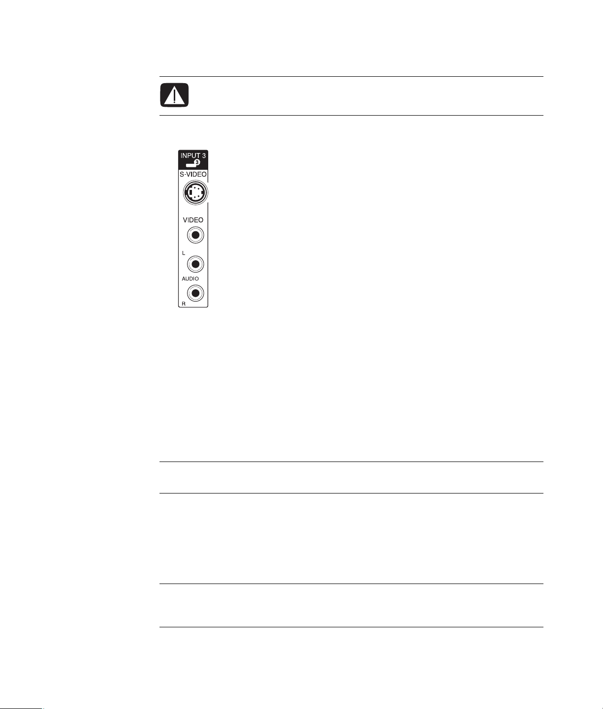
Connecting to S-video
WARNING: In this example, Input 3 has both S-video and Video connectors,
which share the left and right Audio connectors. Connect only one video input
for Input 3.
1 Connect the S-video equipment to the S-video connector (Input 3 in this example):
2 Connect the audio cable connectors to the left and right Audio connectors for Input 3.
3 Connect the cables to the device.
4 Turn on the device, and start play.
5 Plug in the computer.
6 Turn on the computer.
Configuring the TV Tuner
The computer includes a TV tuner that can receive analog or digital (DVB-T) broadcasts.
NOTE: In the countries/regions that do not support digital tuner functionality, you must use
the analog tuner.
You must run the Windows Media Center setup wizard to configure (or confirm) the
following settings on the computer:
Country/region where the computer is being used
Whether you want to receive analog or digital broadcasts (you cannot receive both at
the same time)
NOTE: You need to select analog or digital if you are using an antenna to receive TV
signals. You do not need to perform this part of the setup if you are using a cable or
satellite set-top box.
56 Advanced Setup Guide (features vary by model)

Digital versus analog tuner
The setup wizard makes it easy to perform the tuner configuration. One thing to consider
before starting the wizard is whether you want to receive analog or digital TV signals.
The digital tuner offers the following advantages over analog:
No distortion caused by interference or being far from the broadcast transmitter. If you
are within range of a digital signal, the picture quality is the same, regardless of the
distance from the broadcaster.
Widescreen (16:9) format is supported.
The analog tuner offers the following advantage over digital:
Subtitles and teletext are supported.
In both tuners:
Interactive TV is not supported.
High-Definition (HD) is not supported.
You cannot watch TV if you do not perform the configuration by using the
setup wizard.
In your area, some stations may be available only in analog or digital. You can use
the procedure described in “Initial configuration using Windows Media Center
setup wizard” (step 5) to compare the stations that are available for each type of
tuner.
Initial configuration using Windows Media Center setup wizard
The first time that you start Windows Media Center, the Windows Media Center setup
wizard displays. The Wizard contains Express setup and Custom setup options. The
“Configure tuners, TV signal, and Guide” step is part of the Custom setup.
Perform the initial Windows Media Center configuration as follows:
1 Start the computer, and then perform the initial Windows configuration steps.
2 Start Windows Media Center by clicking the Windows Start Button on the
taskbar, and then Windows Media Center, or by pressing the Windows Media
Center Start button on the remote control. The Windows Media Center setup
wizard displays.
3 Follow the onscreen instructions to complete the Required Setup steps. After
completing the Required Setup steps, the Optional Setup screen displays.
Connecting the Television Signal and Video Cables 57

4 Select Configure tuners, TV signal, and Guide, and then click Next.
5 Follow the onscreen instructions. After performing the Scan for Stations step, the
wizard displays all the TV stations that the selected tuner is able to receive.
6 If the list does not contain stations that you want to view, click Back until you return to
the Select Your TV Signal Type window and select the other tuner setting (analog if you
selected digital first, or digital if you selected analog).
7 Complete the configuration steps until the list of stations for the new tuner type displays
in the Scan for Stations window.
If you are satisfied with the stations that are listed, click Next and complete the
configuration by following the onscreen instructions.
If you are not satisfied with the stations that are listed, return to step 6 and change
back to the original tuner.
Changing the tuner settings
Complete the following procedure to reconfigure the computer if you move it to another
country/region, or change the type of TV signals that you receive (cable, satellite, or
antenna):
1 Click the Windows Start Button on the taskbar, and then click Windows
Media Center.
2 Click Tasks, Settings, TV, and then Set Up TV Signal.
3 Follow the onscreen instructions.
58 Advanced Setup Guide (features vary by model)

Index
A
adjusting monitor 11
adjusting the screen resolution 49
analog video cable/adapter 40
audio cables 40
audio connector 5
Audio Line Out 5
audio input, left and right connectors 4
B
Bluetooth devices 13
C
cable modem, using 12
cables
audio
40
Component video 52
Composite video 52
connecting computer to TV 48
DVI 52
HDMI 52
included 40
S-video 52
TV 39
video 40
coaxial cable
connecting the TV signal source
Composite video cable 40
Composite video connector 4, 6
computer
connecting the remote sensor
connecting the TV signal source 41
connecting TV signal source with set-top box
and VCR
front-panel connectors 2
setting up 1
45
45
43
connecting
devices
digital camera 8
digital video camera 8
dual tuner 42
DVI device 54
HDMI device 53
monitor 51
more than one display 49
peripherals 2
Standard TV 55
Standard video 55
S-video 56
connection
wired network
connector
Audio Line In
Audio Line Out 5
back panel 7
Composite Video In 6
computer 2
FM In 6
headphones 4
keyboard 4
Microphone In 4
modem 7
monitor 7
mouse 4
printer 5
S-video In 5
TV/Cable Ant 6
USB 4, 5
10
13
5
Index 59

D
devices
connecting
digital camera
connecting
digital video camera
connecting to a computer
troubleshooting 9
disabling the TV-Out option 51
disconnecting the TV 51
DVI-I or DVI-D cable 40
10
8, 10
M
manuals
storing
10
microphone connector 4, 5
mini-jack 17
modem
8
connector
monitor
adjusting
monitor connector 7
mouse connector 4
7
11
E
Ethernet connection 13
Ethernet network hub 5
F
FM In connector 6
FM radio antenna
connecting
Found New Hardware message, connecting a digital
camera
6
8
H
headphones
connector
High-Definition
component video
TV, connecting 51
4
52
K
keyboard
connector
4
L
LAN (local area network) 12
antenna 14
checking wireless LAN device 15
connecting Ethernet LAN 5
connecting wireless LAN device 14
setting up 13
using Local Area Network 12
local area network (LAN) 12
N
network interface adapter 5
Network Interface Card (NIC) 13
P
peripherals 2
power connector 4
printer
connecting
connector 5
10
R
RCA stereo cable 41
remote sensor
connecting
Remote IR cable 41
43
S
satellite box 46
scanner, connecting 10
screen resolution
adjusting
setting up computer 1
set-top box 46
speaker systems 21
speakers
connecting multichannel audio speakers to
splitter cable, using 41
surge protector 2
S-video cable 40
S-video In connector 4, 5
49
the computer
17, 19–36
60 Advanced Setup Guide (features vary by model)

T
Television signal/television signals 39
TV
connecting
connecting the TV signal source 41, 44, 46
disconnecting 51
using as a monitor 48
TV coaxial cable
using
TV tuner
connecting TV to computer
signal source 41
48
41
48
U
USB connector 4, 5
using
coaxial cable
TV cables 39
your TV as a monitor 48
44
V
video cables 39, 40
videos
working with home videos
8
W
WEP 15
wired network connection 13
wireless devices 13
wireless LAN 14
wireless LAN connection 14
wireless local area network (WLAN) 13
wireless network
security
wireless network device
checking installation
wireless wide area networks (WWAN) devices 14
WLAN security 15
WPA 15
15
15
Y
Y adapter cables 29
Index 61

Part number: 5992-3542
 Loading...