

HP Pavilion 6618, Pavilion 6619, Pavilion 8770c, Pavilion 8772c, Pavilion 9721 OEM Guide
...Page 1
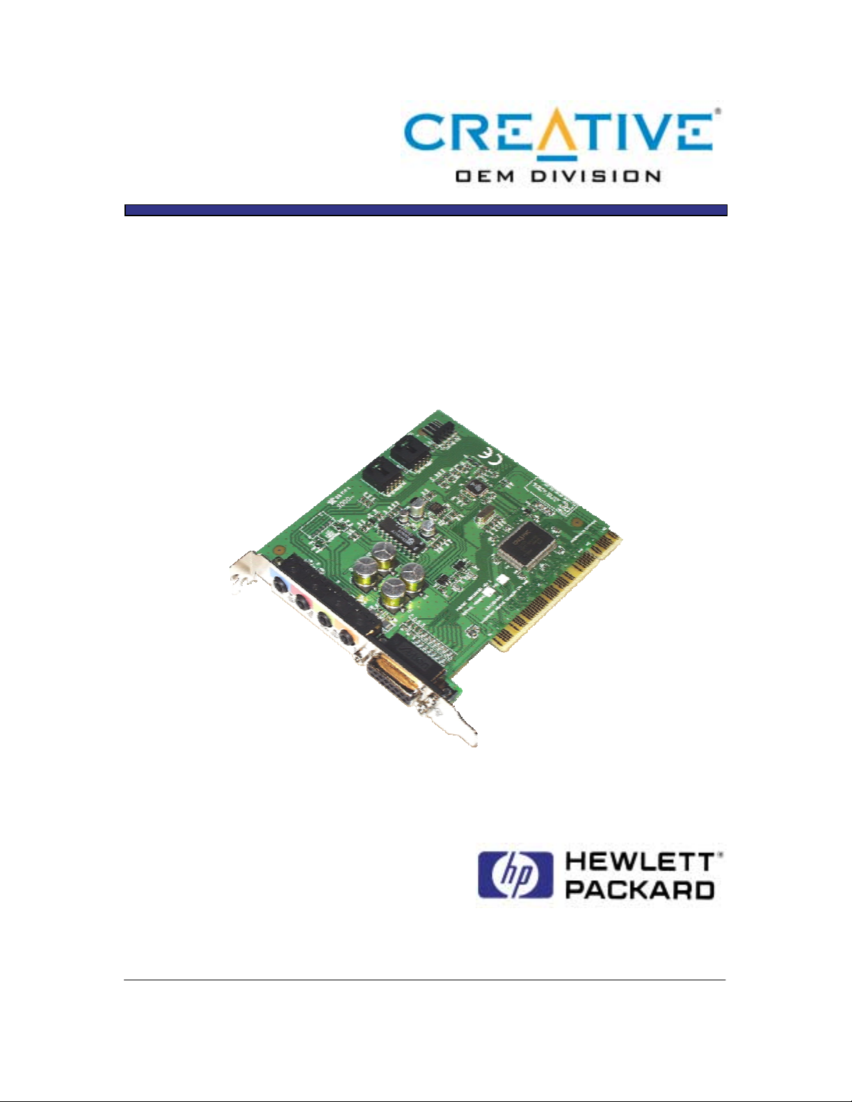
Model CT5801 OEM Guide
Creative Sound Blaster AudioPCI 128
PCI Audio Card Hardware Applications
Revision 1.0, October 25, 2000
Note: This information is Confidential and Proprietary to Creative Labs, Inc. This information is subject to change without prior
notice. Released by OEM Technical Marketing Department. Please direct any inquiries to your regional OEM Sales office. Patent
Pending.
Revision 1.0, 10/25/2000 Page 1
Page 2

Revision History
Revision Written/Changes
Dated Revision History
Made By
1.0 Joanne Scanlon 10-25-00 Updated card picture
to include PC99 colors
on bracket.
Note: This information is Confidential and Proprietary to Creative Labs, Inc. This information is subject to change without prior
notice. Released by OEM Technical Marketing Department. Please direct any inquiries to your regional OEM Sales office. Patent
Pending.
Revision 1.0, 10/25/2000 Page 2
Page 3

Table of Contents
REVISION HISTORY..................................................................................................................................2
INTRODUCTION.........................................................................................................................................4
SB AUDIOPCI 128 CONFIGURATIONS..................................................................................................5
SYSTEM REQUIREMENTS.......................................................................................................................5
SB AUDIOPCI 128 SERIES FEATURES................................................................................................5
IGITIZED SOUNDS
D
S
YNTHESIZED MUSIC
C
OMMUNICATIONS INTERFACE
...........................................................................................................................................5
........................................................................................................................................6
.........................................................................................................................6
Telephone Answering Device (TAD) interface.............................................................................................. 6
C
REATIVE STEREO DIGITAL
MIDI I
NTERFACE
A
DVANCED WAVE TABLE SYNTHESIS
S
AMPLING SUBSYSTEM
3D A
UDIO TECHNOLOGY
J
OYSTICK PORT
SPDIF I
I
NTERFACE
NPUTS AND OUTPUTS
.............................................................................................................................................6
................................................................................................................................................7
...........................................................................................................................................7
/ A
NALOG MIXER
.................................................................................................6
..............................................................................................................6
....................................................................................................................................7
.................................................................................................................................7
......................................................................................................................................7
ES1373 INTEGRATED AUDIO CHIP - GENERAL DESCRIPTION....................................................8
POWER MANAGEMENT...........................................................................................................................9
ES1373 INTEGRATED AUDIO CHIP - BLOCK DIAGRAM...............................................................10
SB AUDIOPCI 128 – ES1373 SERIES CONNECTIONS AND JUMPERS ..........................................11
ADAPTER CABLE FOR S/PDIF FEATURE..........................................................................................12
INTERNAL CONNECTORS - PIN ASSIGNMENTS.............................................................................13
CD A
UDIO CONNECTORS
...............................................................................................................................13
SB AUDIOPCI 128 – ES1373 SERIES SPECIFICATIONS....................................................................14
Note: This information is Confidential and Proprietary to Creative Labs, Inc. This information is subject to change without prior
notice. Released by OEM Technical Marketing Department. Please direct any inquiries to your regional OEM Sales office. Patent
Pending.
Revision 1.0, 10/25/2000 Page 3
Page 4

Introduction
This document is intended to provide a complete technical description of the features and
specifications of the Sound Blaster
AudioPCI 128 is a PCI audio chipset solution from the Ensoniq division of Creative Technology
Ltd. The Sound Blaster
AudioPCI 128 along with an AC97 CODEC offers the next generation
AudioPCI 128 advanced PCI audio cards. The SB
of audio performance in a PC while maintaining full legacy compatibility without old ISA bus
solutions.
The Sound Blaster
AudioPCI 128 utilizes the ES1373 PCI audio chip sold in the OEM
market. SB AudioPCI 128 is a PC99 compliant incorporating 3D Audio technology from
Creative which immerses users in 3D audio space. What's more, the ES1373 supports 3D
Positional Audio, Environmental Audio Extension (EAX) for DirectSound and DirectSound3D,
and custom OEM configuration options for CDDA. In addition, Creative’s 3D Audio technology
dramatically improve s so und c la rit y, spa tia l r ea lism and sound e ffect s, t hro ugh the minimizatio n o f
crosstalk, which will dynamically adjust for monophonic or stereophonic input without user
intervention.
The SB AudioPCI 128 series is fully Plug and Play compliant for ease of use in either DOS,
Windows
Millennium, Windows 2000, Windows 95, Windows 98 or Windows NT applications.
SB AudioPCI 128 provides General MIDI compatibility at an attractive price point. It provides
a professional audio solution for today’s newest generation of game, music and entertainment
software. SB AudioPCI 128 also adds support for General Sound drum kit samples and cuttingedge positional 3D audio for true spatial localization of sounds and complies with the Roland
MT-32 standard for wave table audio. It is fully compliant with Multimedia PC Level 3
specifications and with Microsoft
Multimedia extensions for Windows.
The CT5801 model of the SB AudioPCI 128 adds the capability of a SPDIF output. This
output is shared with the Line-out, and has an audio sensing circuit to determine if the cable
plugged into the jack is for analog or digital output. Details of the internal connection and SPDIF
cable specifications can be found on pages 12 and 13 of this document.
Note: This information is Confidential and Proprietary to Creative Labs, Inc. This information is subject to change without prior
notice. Released by OEM Technical Marketing Department. Please direct any inquiries to your regional OEM Sales office. Patent
Pending.
Revision 1.0, 10/25/2000 Page 4
Page 5
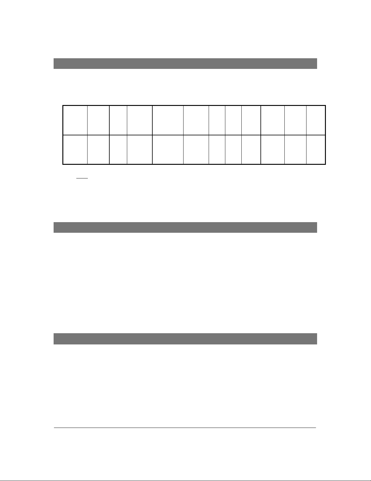
SB AudioPCI 128 Configurations
SB AudioPCI 128 Series is fully configurable as a professional quality audio. The features
shown in the table below are described in detail in the following section of this document. SB
AudioPCI 128 Series is available in the following configuration:
Model Config Host
ES1373 SB
AudioP
CI
128
Key:
Host RAM - Uses system memory
SPDIF - provides output connection to a DAC receiver (ie DAT machine)
2,4,8 MB
Ram
Sound
Sets
!!!!!
!!
!!
3D Sound,
Reverb,
Chorus
!!
!!
Power
Amp
AuxInTADInCD
!!
!!
!!
!!
!!
!!
Bus
Audio
Master
In
!!
!!
PCI
!!
!!
System Requirements
In order to install the SB AudioPCI 128 Series, the target system has to meet the following
minimum requirements:
1. Plug and Play ready Pentium and AMD-K5 90 MHz, or 100% compatible system
2. 16MB RAM
3. 10MB free hard disk space
4. VGA display required
5. Windows
Operating System
6. Available PCI slot
Millennium, Windows 2000, Windows 95, Windows 98 or Windows NT
SB
SPDIF
PCI
Compa
tible
!!
!!
!
!!
SB AudioPCI 128 Series Features
Digitized Sounds
Sound Blaster 16 compatible.
•
• AC97 CODEC supporting stereo sampling 48kHz (Fixed); Multiple sample rate support
• Recording source: microphone, stereo line-in, CD-audio, video, modem or multiple source
recording.
• PCI Bus Master for fast DMA
Advanced 16-bit software-based real time audio compression/decompression system with the
•
following standards:
Note: This information is Confidential and Proprietary to Creative Labs, Inc. This information is subject to change without prior
notice. Released by OEM Technical Marketing Department. Please direct any inquiries to your regional OEM Sales office. Patent
Pending.
Revision 1.0, 10/25/2000 Page 5
Page 6

i. CCITT A-law (16:8)
ii. CCITT µ-law (16:8)
• Up to 128 simultaneous voice polyphony
• Full DOS Game Compatibility
• 3 Stereo inputs and 2 mono inputs can be mixed into the output stream.
Direct I/O space access of the control registers.
•
100 Pin PQFP or TQFP
•
• External SPDIF Connector
Fully Compliant with PC99 Power Management specification
•
Synthesised Music
• 128 Voice WaveTable Synthesizer
Communications Interface
Telephone Answering Device (TAD) interface
• Telephony answering device for modem connection. Allows a single microphone and stereo
speaker set to be used for both voice modem and sound card audio applications (message
recording and playback, speakerphone, etc.)
Creative Stereo Digital / Analog Mixer
• Output mixing of all audio sources: Digitize d sounds, synthesized music, line -i n, CD-audio,
TV-tuner, microphone.
• Input mixing sources: Synthesized music, microphone, video input, CD-audio, line-in
• Multiple source recording and L/R channels may be swapped or mixed.
• 7 channel mixer for access to digitized sound, synthesized music, microphone, CD-audio,
line-in, video, phone
• Spatial audio control for digital audio and music synthesizer
• Reverb and chorus control for music synthesizer
MIDI Interface
MPU-401 UART
•
Advanced Wave Table Synthesis
• Creative Advanced Synthesis Engine
• 128 voice polyphony and multi-timbral capability
• 128 GM wavetable instruments
• GS sound set + 10 drum kits in 4 & 8 MB sample sets
16 MIDI channels
•
128 MT-32 compatible instruments
•
Digital effects engine for reverb and chorus
•
Note: This information is Confidential and Proprietary to Creative Labs, Inc. This information is subject to change without prior
notice. Released by OEM Technical Marketing Department. Please direct any inquiries to your regional OEM Sales office. Patent
Pending.
Revision 1.0, 10/25/2000 Page 6
Page 7

• 2MB, 4MB, & 8MB sample sets
Sampling Subsystem
• Host memory support
• Virtually unlimited variations of sound
3D Audio Technology
• Supports EAX 1.0
Multi-algorithm Reverb and Chorus
•
• Support Microsoft
• Support Aureal A3D API
• Improves so und clarity, spatial realism and sound effects, t hrough the minimization of crosstalk
• Dynamically adjust for monophonic or stereophonic input without user intervention
Joystick Port
• Standard PC joystick port for 1 or 2 joysticks.
SPDIF Interface
2-channel digital audio interface
•
• Output connector to a DAC receiver (i.e. digital speakers)
DirectSound 3D
Inputs and Outputs
•••• Stereo 2W/Channel Power Amplifier
• Line In
• Line Out/SPDIF Out (SPDIF Out optional)
Microphone In
•
CD In
•
• TAD
TV Tuner
•
Joystick/Midi
•
Note: This information is Confidential and Proprietary to Creative Labs, Inc. This information is subject to change without prior
notice. Released by OEM Technical Marketing Department. Please direct any inquiries to your regional OEM Sales office. Patent
Pending.
Revision 1.0, 10/25/2000 Page 7
Page 8

ES1373 Integrated Audio Chip - General Description
The ES1373 solution is Sound Blaster 16 compatible via emulation, Roland MPU401
compatible via emulation and in full compliance with Multimedia PC Level 3 specifications. In
addition, the ES1373 meets Plug and Play specifications, eliminating any requirement for the user
to select I/O and DMA ad dress settings through ha rdware or software. T he card is auto matically
recognized and configured by the Plug and Play host PC during installation
ES1373 is a PCI bus master and slave device that is best understood by looking at the device as
four interactive subsystems: the PCI interface, DMA control, LEGACY functions, and the
CODEC.
The PCI subsystem is a bus master interface that performs the memory accesses to keep the
audio cache buffers full and empties the A/D Converter ( or I
2
S input) buffer to main memory as
required. The fundamental concept of ES1373 is that the PCI interface controller has a sufficiently
large internal (on-chip) memory cache to meet the memory bandwidth requirements. There is a
sound cache block of 64 bytes for each of the audio channels. It is the responsibility of the DMA
control and the software to keep the buffers full.
All system control registers are accessed via I/O on the PCI bus. The ES1373 uses 16 Long
Words in the I/O space for control registers. All registers are read as Long Words. All registers
are written in byte word or long word format.
The ES1373 essentially implements a 3-channel DMA controller. These virtual DMA
channels are implemented via the CCB, PCI and Serial interface modules. The serial interface
signals the CCB module when a cache transfer is required (playback or record). The CCB module
then signals the PCI module to initiate a bus master data transfer. At this point the CCB and PCI
modules will control the data transfer between host system memory and the ES1373 internal cache.
The LEGACY subsystem is the circuitry required to perform Sound Blaster, OPL-FM and
MPU-401 emulation. Functionally the ES1373 traps on access of the Sound Blaster registers and
then issues the appropriate IRQ or SERR command on the PCI bus. The ES1373 handles the
Legacy DMA function in a similar fashion. The exact functionality of the block cannot be fully
disclosed at this time due to pending patent protection for the application of this technique.
The CODEC controller supports any AC97 compliant CODEC. The functionality of the A/D
and D/A sections are similar to those found in other standard CODECs. The A/D portion of the
CODEC is handled as an independent asynchronous event with a DMA buffer control structure.
Each time the A/D FIFO is filled, a Bus Master request occurs and the FIFO is transferred to main
memory.
The ES1373 also incorporates a SPDIF output. This output is capable of providing stereo
digital audio or compressed AC3 data from a soft DVD decoder.
Note: This information is Confidential and Proprietary to Creative Labs, Inc. This information is subject to change without prior
notice. Released by OEM Technical Marketing Department. Please direct any inquiries to your regional OEM Sales office. Patent
Pending.
Revision 1.0, 10/25/2000 Page 8
Page 9

Power Management
All power management of the system is under software control. The AC97 CODEC and
ES1373 can be powered down separately. Neither chip loses register information when powered
down.
The ES1373 can be power managed by shutting down various sub-systems. The following
blocks can be individually powered down: Joystick, UART, and Serial Interface. Although these
blocks can be individually disabled this will not save an appreciable amount of power. ES1373
can also individually internally shut down the PCI clock and the Crystal input clock. The PCI
clock when shut down will still be active to the PCI and Interrupt/Chip Select modules. The
Crystal clock when shut down will be shut down for all internal modules as well as the output
connection to the AC97 CODEC.
During operation, the ES1373 ASIC will have a typical power dissipation of 150mW. In
power down, the ES1373 ASIC will have a typical power dissipation of 15mW.
CODEC Power Management
The AC97 CODEC is powered down by setting bit 1 (of control bits 7 - 0) in control register
16 (hex) to a zero. The AC97 CODEC control registers are written through the CODEC Interface
block at address 14 (hex).
ES1373 Power Management
As mentioned above, the Joystick, UART, and Serial Interface modules of the ES1373 chip
can be individually powered down. The remaining modules will be in a powered up condition.
The ES1373 modules are powered down by setting bits 6 - 2 (of control bits 31 - 0) to zero. The
ES1373 control register is located in the IRQ and Chip Select Block at address 00 (hex). Note that
the Serial Interface actually has three separate enable bits, one for each of the playback channels
and one for the record channel.
Although these blocks can be ind i vidually disabled this will not save an appreciable amount of
power. ES1373 can also individually internally shut down the PCI clock and the Crystal input
clock. The PCI clock when shut down will still be active to the PCI and Interrupt/Chip Select
modules. The Crystal clock when shut down will be shut down for all internal modules as well as
the output connection to the AC97 CODEC.
Note: This information is Confidential and Proprietary to Creative Labs, Inc. This information is subject to change without prior
notice. Released by OEM Technical Marketing Department. Please direct any inquiries to your regional OEM Sales office. Patent
Pending.
Revision 1.0, 10/25/2000 Page 9
Page 10
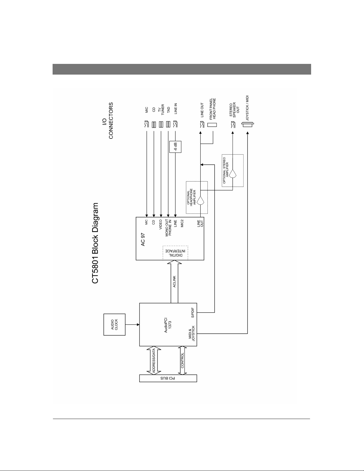
ES1373 Integrated Audio Chip - Block Diagram
Note: This information is Confidential and Proprietary to Creative Labs, Inc. This information is subject to change without prior
notice. Released by OEM Technical Marketing Department. Please direct any inquiries to your regional OEM Sales office. Patent
Pending.
Revision 1.0, 10/25/2000 Page 10
Page 11

SB AudioPCI 128 – ES1373 Series Connections and Jumpers
The board consists of the following connectors that support the connection of internal
devices or hardware configuration changes:
1. CD Audio In – J6
4 pin Molex CD Audio connector
•
2. TV Tuner – J8
• 4 pin Molex connector
• Connector for TV Tuner, IDE CD Audio or other auxiliary audio input
3. TAD I/O – J10
Connection to a standard voice modem
•
The card features the following external jacks and connectors on the back panel:
J1 - Stereo jack for Line in (Black jack with blue color and wording “IN” on bracket)
J2 - Stereo jack Mic (Black jack with microphone symbol and pink color on bracket)
J3 - Stereo jack for Line-out (Black jack with green color and wording “OUT” on bracket)
J4 – Stereo speaker output (Black jack with stereo symbol and orange color on bracket)
J5 - Joystick/Midi port (Black jack with joystick symbol on bracket)
The AudioPCI 128 ES1373 Series cards are 2 layer PCB construction. The descriptions for
all back panel connections are located on the bracket.
Note: This information is Confidential and Proprietary to Creative Labs, Inc. This information is subject to change without prior
notice. Released by OEM Technical Marketing Department. Please direct any inquiries to your regional OEM Sales office. Patent
Pending.
Revision 1.0, 10/25/2000 Page 11
Page 12
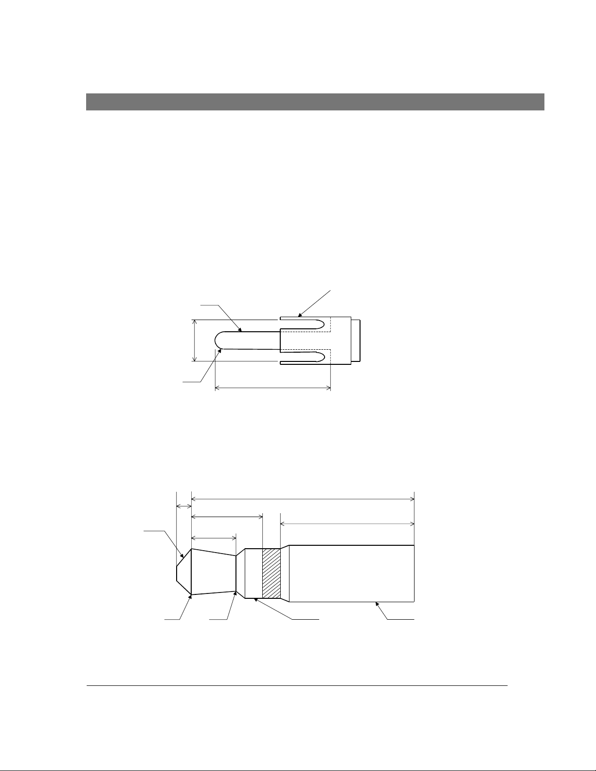
Adapter Cable for S/PDIF Feature
Length: 6 Feet
Impedance: 75 Ohm
Type: Coaxial
Soundcard End: 3.5 mm Male (Earphone) Mono Plug
Receiver End: RCA (Male) Plug
The cable shield is connected to the sleeve of the 3.5 mm plug and the sleeve of the RCA plug. The center
conductor is connected to the tip of both the RCA plug and the 3.5 mm plug.
sleeve
∅
3.2
RCA Plug
MONO
45°
∅3
∅8.2
R1.4
14
3.5 mm Plug
1
3.8
3
Tip
13
8.5
∅3.2∅2.5
∅3.5
sleeve
Note: This information is Confidential and Proprietary to Creative Labs, Inc. This information is subject to change without prior
notice. Released by OEM Technical Marketing Department. Please direct any inquiries to your regional OEM Sales office. Patent
Pending.
Revision 1.0, 10/25/2000 Page 12
Page 13
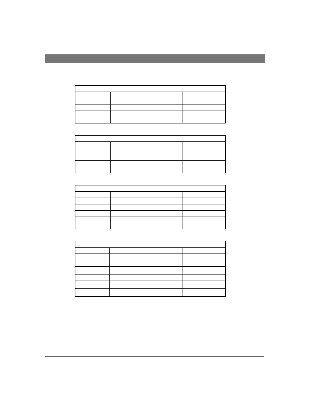
Internal Connector s - Pin Assignments
CD Audio Connectors
PIN SIGNAL I/O
1 Left Channel IN
2 Ground IN
3 Ground IN
4 Right Channel IN
PIN SIGNAL I/O
1 Left Channel IN
2 Ground IN
3 Ground IN
4 Right Channel IN
PIN SIGNAL I/O
1 Modem Audio In IN
2 Ground IN
3 Ground IN
4 Boosted Mic Output
J6 - Molex CD-IN Pin Assignments
J8 - Molex TV Tuner Pin Assignments
J10 - Molex TAD Pin Assignments
IN
30dB
J12 Front Panel Header Signal
PIN SIGNAL I/O
1 Front Panel Left Out OUT
2 Front Panel Left Return IN
3 Ground IN
4 Ground IN
5 Front Panel Ri ght Return IN
6 Front Panel Right Out OUT
Note: This information is Confidential and Proprietary to Creative Labs, Inc. This information is subject to change without prior
notice. Released by OEM Technical Marketing Department. Please direct any inquiries to your regional OEM Sales office. Patent
Pending.
Revision 1.0, 10/25/2000 Page 13
Page 14

SB AudioPCI 128 – ES1373 Series Specifications
Typical Audio Performance
Frequency Response 20 Hz to 20 kHz (Source: Line in)
(+0/-3dB) 20 Hz to 20 kHz (Source: Mic)
Line-In Voltage Range 0 to 2 Vrms
Line-Out voltage at 0dB 0 to 2 Vrms (10kohms load)
Reference signal 1KHz (measured with wide-band filter 22Hz-22kHz):
Signal to Noise Ratio > 90 dBr (Source: Line-in)
THD+ N .005% (Source: Line-in)
.01% (Source: 35dBu Mic-in)
Microphone Input Range 0 to 100 mVrms
Line-In Impedance 10 kohms
CD Audio-In Impedance 10 kohms
CD Audio-In Input Range 0 to 1 Vrms
Power Consumption (estimated)
+5 Volt Current Consumption 50 mA (Typ)
+12 Volt Current Consumption 75 mA (Typ)
-12 Volt Current Consumption 35 mA (Typ)
Temperature range
Operation 10 to 50 degree C
Non-operating -40 to 125 degree C
Note: This information is Confidential and Proprietary to Creative Labs, Inc. This information is subject to change without prior
notice. Released by OEM Technical Marketing Department. Please direct any inquiries to your regional OEM Sales office. Patent
Pending.
Revision 1.0, 10/25/2000 Page 14
Page 15

Creative Offices
International inquiries:
Creative Technology Ltd.
31 International Business Park
Creative Resource
Singapore 609921
Tel: +65 895 4000
Americas Inquiries:
Creative Labs, Inc.
901 McCarthy Boulevard
Milpitas, CA 95035
Tel: +1 (408) 428 6600
Fax: +1 (408) 428 2394
Fax: +65 895 4050
Creative Media K.K.
Kanda Eight B ldg. 3F
4-6-7 Soto-Kanda Chiyoda-Ku
Tokyo 101
Japan
Tel: +81 3 3256 5577
Fax: +81 3 3256 5547
European inquiries:
Creative Labs, UK
Unit 2, The Pavilions
Ruscombe Business Park
Ruscombe, Berkshire
RG10 9NN
ENGLAND
Tel: +44 1 (734) 344322
Fax: +44 1 (734) 320300
All specifications are subject to change without prior notice. All specifications may not be applicable to all
models. Sound Blaster, Wave Blaster, Advanced WavEffects, AudioPCI, AWE32, SB32, ViBRA, CQM,
Ensoniq, the Sound Blaster logo and the Creative logo are trademarks of Creative Technology Ltd. IBM is
a registered trademark of International Business Machines Corporation. Microsoft and MS-DOS are
registered trademarks and Windows, Windows 95, Windows 97, and Windows NT are trademarks of
Microsoft Corporation. All other trademarks are owned by their respective compan
Note: This information is Confidential and Proprietary to Creative Labs, Inc. This information is subject to change without prior
notice. Released by OEM Technical Marketing Department. Please direct any inquiries to your regional OEM Sales office. Patent
Pending.
Revision 1.0, 10/25/2000 Page 15
Page 16

 Loading...