

HP Pavilion 15-CS2999, Pavilion 15-CS0000, Pavilion 15-CS1999, Pavilion 15T-CS100, Pavilion 15T-CS000 Maintenance And Service Manual
...
Maintenance and Service Guide
HP Pavilion 15 Laptop PC
IMPORTANT! This document is intended for HP authorized service
providers only.

© Copyright 2018, 2019 HP Development
Company, L.P.
Bluetooth is a trademark owned by its
proprietor and used by HP Inc. under license.
Intel, Core, and Pentium are trademarks of Intel
Corporation or its subsidiaries in the U.S.
and/or other countries. NVIDIA and GeForce are
trademarks and/or registered trademarks of
NVIDIA Corporation in the U.S. and other
countries. Microsoft and Windows are either
registered trademarks or trademarks of
Microsoft Corporation in the United States
and/or other countries. SD, SDHC, and SDXC are
trademarks or registered trademarks of SD-3C
in the United States, other countries or both.
The information contained herein is subject to
change without notice. The only warranties for
HP products and services are set forth in the
express warranty statements accompanying
such products and services. Nothing herein
should be construed as constituting an
additional warranty. HP shall not be liable for
technical or editorial errors or omissions
contained herein.
Fourth Edition: February 2019
First Edition: May 2018
Product notice
This user guide describes features that are
common to most models. Some features may
not be available on your computer.
Not all features are available in all editions of
Windows. This computer may require upgraded
and/or separately purchased hardware, drivers
and/or software to take full advantage of
Windows functionality. Go to
http://www.microsoft.com for details.
Software terms
By installing, copying, downloading, or
otherwise using any software product
preinstalled on this computer, you agree to be
bound by the terms of the HP End User License
Agreement (EULA). If you do not accept these
license terms, your sole remedy is to return the
entire unused product (hardware and software)
within 14 days for a full refund subject to the
refund policy of your seller.
For any further information or to request a full
refund of the price of the computer, please
contact your seller.
Document Part Number: L19436-004

Safety warning notice
CAUTION: To reduce the possibility of heat-related injuries or of overheating the device, do not place
the device directly on your lap or obstruct the device air vents. Use the device only on a hard, at surface. Do
not allow another hard surface, such as an adjoining optional printer, or a soft surface, such as pillows or rugs
or clothing, to block airow. Also, do not allow the AC adapter to contact the skin or a soft surface, such as
pillows or rugs or clothing, during operation. The device and the AC adapter comply with the user-accessible
surface temperature limits dened by the International Standard for Safety of Information Technology
Equipment (IEC 60950–1).
iii

iv Safety warning notice

Table of contents
1 Product description ....................................................................................................................................... 1
2 Getting to know your computer ...................................................................................................................... 7
Right side ............................................................................................................................................................... 7
Left side ................................................................................................................................................................. 8
Display .................................................................................................................................................................... 9
Keyboard area ...................................................................................................................................................... 11
TouchPad ........................................................................................................................................... 11
Lights ................................................................................................................................................. 12
Power button, speakers, and vent .................................................................................................... 13
Special keys ....................................................................................................................................... 14
Action keys ........................................................................................................................................ 15
Bottom ................................................................................................................................................................. 16
Labels ................................................................................................................................................................... 16
3 Illustrated parts catalog .............................................................................................................................. 18
Computer components ........................................................................................................................................ 18
Display assembly components ............................................................................................................................ 23
Mass storage devices ........................................................................................................................................... 26
Cables ................................................................................................................................................................... 27
Miscellaneous parts ............................................................................................................................................. 28
4 Removal and replacement procedures preliminary requirements .................................................................... 29
Tools required ...................................................................................................................................................... 29
Service considerations ......................................................................................................................................... 29
Plastic parts ....................................................................................................................................... 29
Cables and connectors ...................................................................................................................... 29
Drive handling ................................................................................................................................... 30
Workstation guidelines ..................................................................................................................... 30
Electrostatic discharge information .................................................................................................................... 30
Generating static electricity .............................................................................................................. 31
Preventing electrostatic damage to equipment ............................................................................... 31
Personal grounding methods and equipment .................................................................................. 32
Grounding the work area ................................................................................................................... 32
Recommended materials and equipment ........................................................................................ 32
Packaging and transporting guidelines .............................................................................................................. 33
v

5 Removal and replacement procedures for authorized service provider parts .................................................... 34
Component replacement procedures .................................................................................................................. 34
Preparation for disassembly ............................................................................................................. 34
Bottom cover ..................................................................................................................................... 34
Battery ............................................................................................................................................... 37
Display assembly ............................................................................................................................... 39
Hard drive .......................................................................................................................................... 50
WLAN module .................................................................................................................................... 52
Solid-state drive ................................................................................................................................ 54
Optane memory module ................................................................................................................... 55
Memory module ................................................................................................................................ 56
Memory card reader board ................................................................................................................ 57
USB board (select products only) ...................................................................................................... 59
TouchPad ........................................................................................................................................... 60
Lock bracket ...................................................................................................................................... 63
Fan(s) ................................................................................................................................................. 65
Heat sink ............................................................................................................................................ 67
System board .................................................................................................................................... 70
Speakers ............................................................................................................................................ 74
Power connector cable ...................................................................................................................... 76
Top cover with keyboard ................................................................................................................... 78
6 Using Setup Utility (BIOS) ............................................................................................................................. 79
Starting Setup Utility (BIOS) ................................................................................................................................ 79
Updating Setup Utility (BIOS) .............................................................................................................................. 79
Determining the BIOS version ........................................................................................................... 79
Downloading a BIOS update .............................................................................................................. 80
7 Using HP PC Hardware Diagnostics ................................................................................................................ 81
Using HP PC Hardware Diagnostics Windows (select products only) ................................................................. 81
Downloading HP PC Hardware Diagnostics Windows ....................................................................... 81
Downloading the latest HP PC Hardware Diagnostics Windows version ....................... 82
Downloading HP Hardware Diagnostics Windows by product name or number
(select products only) ..................................................................................................... 82
Installing HP PC Hardware Diagnostics Windows ............................................................................. 82
Using HP PC Hardware Diagnostics UEFI ............................................................................................................. 82
Starting HP PC Hardware Diagnostics UEFI ....................................................................................... 83
Downloading HP PC Hardware Diagnostics UEFI to a USB ash drive .............................................. 83
Downloading the latest HP PC Hardware Diagnostics UEFI version .............................. 83
Downloading HP PC Hardware Diagnostics UEFI by product name or number
(select products only) ..................................................................................................... 83
vi

Using Remote HP PC Hardware Diagnostics UEFI settings (select products only) ............................................. 84
Downloading Remote HP PC Hardware Diagnostics UEFI ................................................................. 84
Downloading the latest Remote HP PC Hardware Diagnostics UEFI version ................. 84
Downloading Remote HP PC Hardware Diagnostics UEFI by product name or
number ............................................................................................................................ 84
Customizing Remote HP PC Hardware Diagnostics UEFI settings .................................................... 84
8 Backing up, restoring, and recovering ........................................................................................................... 86
Backing up information and creating recovery media ........................................................................................ 86
Using Windows tools ......................................................................................................................... 86
Using the HP Cloud Recovery Download Tool to create recovery media (select products only) ..... 86
Restoring and recovery ........................................................................................................................................ 87
Restoring, resetting, and refreshing using Windows tools .............................................................. 87
Recovering using HP Recovery media ............................................................................................... 87
Changing the computer boot order ................................................................................................... 87
9 Specications .............................................................................................................................................. 88
10 Power cord set requirements ...................................................................................................................... 89
Requirements for all countries ............................................................................................................................ 89
Requirements for specic countries and regions ................................................................................................ 89
11 Recycling .................................................................................................................................................. 91
Index ............................................................................................................................................................. 92
vii

viii

1 Product description
Table 1-1 Product components and their descriptions
Category Description
Product Name HP Pavilion 15 Laptop PC
Model numbers:
15-cs0000 – 15-cs0999; 15-cs1000 – 15-cs1999; 15-cs2000 – 15-cs2999
15t-cs000; 15t-cs100; 15t-cs200
Processors 8th generation Intel® Core™ processors
i7-8565U 1.80 GHz (SC turbo up to 4.60 GHz) quad core processor (8.0 MB L3 cache, 2400-MHz FSB, 15 W)
i7-8550U 1.80 GHz (SC turbo up to 4.00 GHz) quad core processor (8.0 MB L3 cache, 2400-MHz FSB, 15 W)
i5-8265U 1.60 GHz (SC turbo up to 3.90 GHz) quad core processor (6.0 MB L3 cache, 2400-MHz FSB, 15 W)
i5-8250U 1.60 GHz (SC turbo up to 3.40 GHz) quad core processor (6.0 MB L3 cache, 2400-MHz FSB, 15 W)
i3-8145U 2.10 GHz (SC turbo up to 3.90 GHz) dual core processor (4.0 MB L3 cache, 2400-MHz FSB, 15 W)
i3-8130U 2.20 GHz (SC turbo up to 3.40 GHz) dual core processor (4.0 MB L3 cache, 2400-MHz FSB, 15 W)
7th generation Intel processors
Core i7-7500U 2.70 GHz (SC turbo up to 3.50 GHz) dual core processor (4.0 MB L3 cache, 2133-MHz FSB, 15 W)
Pentium® Gold 4415U 2.30 GHz, dual core processor (2.0 MB L3 cache, 2133-MHz FSB, 15 W)
Graphics Support for HD decode, DX12, and high-denition multimedia interface (HDMI)
Supports Optimus (select products only)
Supports GPS (GPU Performance Scaling)
Supports MR ready
Internal graphics
Intel UHD Graphics 620 (8th generation Intel Core processors)
Intel HD Graphics 620 (7th generation Intel Core processors)
Intel HD Graphics 610 (7th generation Intel Pentium processors)
Hybrid graphics
NVIDIA GeForce® GTX1050 with 2 GB of discrete video memory
NVIDIA GeForce GTX1050 with 3 GB of discrete video memory
NVIDIA GeForce GTX1050 with 4 GB of discrete video memory
NVIDIA GeForce GTX1050Ti with 4-GB of discrete video memory
NVIDIA GeForce MX250 with up to 4 GB of discrete video memory
NVIDIA GeForce MX250 with up to 2 GB of discrete video memory
1

Table 1-1 Product components and their descriptions (continued)
Category Description
NVIDIA GeForce MX150 with up to 4 GB of discrete video memory
NVIDIA GeForce MX150 with up to 2 GB of discrete video memory
NVIDIA GeForce MX130 with up to 2 GB of discrete video memory
Panel 15.6-in, white light-emitting (WLED), slim, eDP, 16:9 aspect ratio, narrow bezel
High denition (HD) (1366 × 768), BrightView, SVA, 220 nits (select products only)
HD (1366 × 768), BrightView, SVA, 220 nits, Touch-on Panel (TOP) (select products only)
HD (1366 × 768), anti glare, SVA, 220 nits (select products only)
Full high-denition (FHD) (1920 × 1080), BrightView, UWVA, 220 nits (select products only)
FHD (1920 × 1080), BrightView, UWVA, 250 nits, Touch-on Panel (TOP); touch solution with bezel, multi-touch
enabled (select products only)
FHD (1920 × 1080), anti glare, UWVA, 220 nits (select products only)
FHD (1920 × 1080), anti glare, SVA, 220 nits (select products only)
FHD (1920 × 1080), anti glare, UWVA, 300 nits, 72% CG (select products only)
Memory Two SODIMM memory module slots, non-customer-accessible/non-upgradable
Supports up to 16 GB of system memory
DDR4-2400 dual channel support (select products only)
DDR4-2133 dual channel support (select products only)
Supports the following congurations:
● 16384 GB (8192 GB × 2)
● 12288 GB (8192 GB × 1 + 4096 GB × 1)
● 8192 GB (8192 GB × 1 or 4096 GB × 2)
● 6144 GB (4096 GB × 1 + 2048 GB × 1)
● 4096 GB (4096 GB × 1)
Storage Support for 7.2 mm/9.5 mm, SATA, 2.5-inch hard drives (select models only)
Support for solid-state drive + hard drive (select products only)
Support for M.2 SATA/PCIe solid-state drive (select products only)
Accelerometer/Hard drive protection support
Single hard drive congurations (select products only)
2 TB, 5400 rpm, 7.2 mm
1 TB, 5400 rpm, 7.2 mm
500 GB, 5400 rpm, 7.0 mm
Dual storage congurations (select products only)
256 GB, PCIe, value, solid-state drive + 1 TB, 5400 rpm, 7.2 mm hard drive
256 GB, SATA, TLC, solid-state drive + 1 TB, 5400 rpm, 7.2 mm hard drive
2 Chapter 1 Product description

Table 1-1 Product components and their descriptions (continued)
Category Description
128 GB, SATA, TLC, solid-state drive + 2 TB, 5400 rpm, 7.2 mm hard drive
128 GB, SATA, TLC, solid-state drive + 1 TB, 5400 rpm, 7.2 mm hard drive
128 GB, SATA, TLC, solid-state drive + 500 GB, 5400 rpm, 7.0 mm hard drive
M.2 SATA-3, TLC, solid-state drive (select products only)
256 GB
128 GB
M.2, PCIe, NVMe, solid-state drive
512 GB, TLC
512 GB
256 GB
Intel Optane (3D Xpoint) Solution, PCIe, Gen3 × 2, M.2, solid-state drive (select products only)
16 GB (Optane memory module) + 1 TB, 5400 rpm, 7.2 mm hard drive
Camera HP Wide Vision FHD infrared camera with indicator light and 2 infrared lights, USB 2.0, FHD hybrid BSI sensor,
f2.2, 88° wide eld of vision
1080p by 30 frames per second
Supports Windows® Hello
Dual array Digital Microphones with appropriate software - beam forming, echo cancellation, noise suppression
HP Wide Vision HD camera with indicator light, USB 2.0, HD BSI sensor, f2.0, 88° wide eld of vision
720p by 30 frames per second
Dual array Digital Microphones w/ appropriate software - beam forming, echo cancellation, noise suppression
Audio Audio brand: B&O
Audio control panel: B&O Audio Control
Supports HP Audio Boost
Dual speakers
RJ-45 (network)
jack
Sensors Accelerometer (select products only)
Wireless Compatible with Miracast-certied devices
Integrated 10/100/1000 NIC
Integrated wireless options with a single antenna
Intel Dual Band Wireless-AC 9461 802.11ac 1 × 1 Wi-Fi + Bluetooth® 5 Combo Adapter (non-vPro) (select products
only)
Integrated wireless options with dual antennas (M.2/CNVi)
Intel Dual Band Wireless-AC 9560 802.11ac 2 × 2 Wi-Fi + Bluetooth 5 (non-vPro) (MU-MIMO supported) (select
products only)
Intel Dual band wireless-AC 3168 802.11ac 1 × 1 Wi-Fi + Bluetooth 4.2 Combo Adaptor (non-vPro) (select products
only)
3

Table 1-1 Product components and their descriptions (continued)
Category Description
Intel Dual Band Wireless-AC 7265 802.11ac 2 × 2 Wi-Fi + Bluetooth 4.2 Combo Adapter (non-vPro) (select products
only)
Realtek RTL8822BE 802.11ac 2 × 2 Wi-Fi + Bluetooth 4.2 Combo Adapter (MU-MIMO supported) (select products
only/)
Integrated wireless options with single antenna (M.2/PCIe)
Realtek RTL8821CE 802.11ac 1 × 1 Wi-Fi + Bluetooth 4.2 Combo Adapter (MU-MIMO supported) (select products
only)
Realtek RTL8723DE 802.11bgn 1 × 1 Wi-Fi + Bluetooth 4.2 Combo Adapter (select products only)
Media card
reader
Internal card
expansion
Ports Hot plug/unplug and auto detect for correct output to wide-aspect vs standard aspect video (auto adjust panel
Keyboard/
TouchPad
Supports SD™/SDHC™/SDXC™
Push-push insertion/removal
One M.2 slot for solid-state drive
One M.2 slot for WLAN
resolution to t embedded panel and external monitor connected)
AC Smart Pin adapter plug
Audio-out (headphone)/audio-in (microphone) combo jack
HDMI v2.0 supporting up to 1920 × 1080 @ 60Hz
RJ-45 (network) jack
USB 3.1 Type-A ports (2, right side)
USB Type-C port; USB 3.1 Gen 1 (left side); supports data transfer
HDMI supporting up to 4096 × 2160 @ 60Hz (select products only)
Keyboard
Full-sized, two coat paint, island-style keyboard with numeric keypad
Full-sized, three-coat paint, backlit, island-style keyboard with numeric keypad
TouchPad
Image sensor
MultiTouch gestures enabled
Support for Modern TrackPad gestures
Taps enabled as default
Power
requirements
Battery
4-cell, 68 Whr, prismatic/polymer battery (select models only)
3-cell, 41 Whr, prismatic/polymer battery
Supports battery fast charge
AC adapter
120 W HP Smart AC adapter with power cord
4 Chapter 1 Product description

Table 1-1 Product components and their descriptions (continued)
Category Description
90 W HP Smart AC adapter with power cord
65 W HP Smart AC adapter (EM) with power cord
65 W HP Smart AC adapter with power cord
45 W HP Smart AC adapter with power cord
Power cord
1.0 m conventional power cord with a C5 connector
1.0 m conventional power cord with a C5 connector + Japan plug adapter
Security Nano security cable slot
U2F (Universal 2nd Factor Authentication)
Support for Trusted Platform Module (fTPM) 2.0
Operating
system
FreeDOS 2.0
Windows® 10 Home 64
Windows 10 Home 64 Web/Kiosk
Windows 10 Home 64 Chinese Market CPPP
Windows 10 Home 64 High-End Chinese Market CPPP
Windows 10 Home 64 Plus
Windows 10 Home 64 Plus Microsoft Signature
Windows 10 Home 64 Plus QVC
Windows 10 Home 64 Plus Single Language
Windows 10 Home 64 Plus Single Language Africa Market PPP
Windows 10 Home 64 Plus Single Language APAC EM PPP
Windows 10 Home 64 Plus Single Language India Market PPP
Windows 10 Home 64 Plus Single Language Indonesia Market PPP
Windows 10 Home 64 Plus Web/Kiosk
Windows 10 Home 64 QVC
Windows 10 Home 64 Single Language
Windows 10 Home 64 Single Language Africa Market PPP
Windows 10 Home 64 Single Language APAC EM PPP
Windows 10 Home 64 Single Language India Market PPP
Windows 10 Home 64 Single Language Indonesia Market PPP
Windows 10 Home 64 Single Language Value Africa Market PPP
Windows 10 Home 64 Single Language Value APAC EM PPP
Windows 10 Home 64 Single Language Value India Market PPP
5

Table 1-1 Product components and their descriptions (continued)
Category Description
Windows 10 Home 64 Single Language Value Indonesia Market PPP
Windows 10 Home 64 Value Notebook Single Language
Windows 10 Home 64 Value Notebook Single Language SEAP
Windows 10 Home 64 Value Notebook Single Language select GEO
Windows 10 Home S 64
Windows 10 Home S 64 Value
Windows 10 Home S 64 Value Web/Kiosk
Windows 10 Home S 64 S Value QVC
Windows 10 Pro 64
Windows 10 Pro 64 Web/Kiosk
Windows 10 Pro 64 QVC
Serviceability End user replaceable parts
AC adapter
6 Chapter 1 Product description
2 Getting to know your computer
Your computer features top-rated components. This chapter provides details about your components, where
they are located, and how they work.
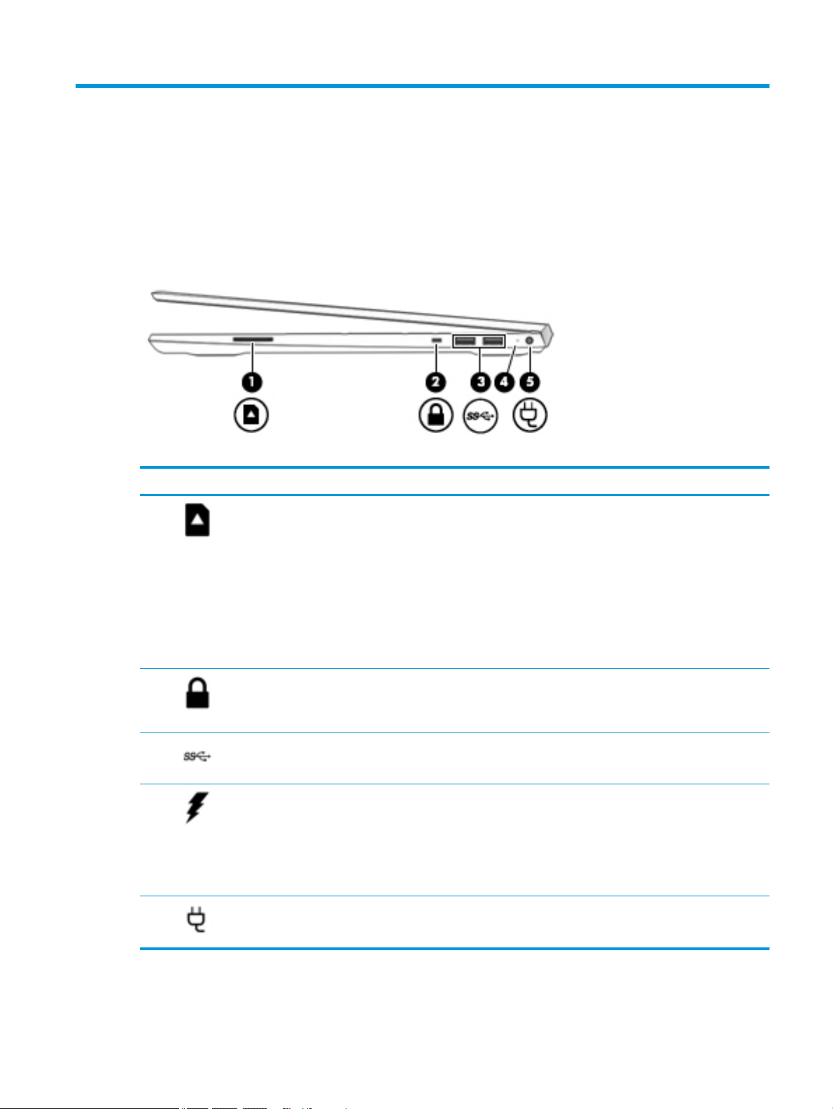
Right side
Table 2-1 Right-side components and their descriptions
Component Description
(1) Memory card reader Reads optional memory cards that enable you to store, manage, share, or access
information.
To insert a card:
1. Hold the card label-side up, with connectors facing the computer.
2. Insert the card into the memory card reader, and then press in on the card
until it is rmly seated.
To remove a card:
▲ Press in on the card, and then remove it from the memory card reader.
(2) Security cable slot Attaches an optional security cable to the computer.
NOTE: The security cable is designed to act as a deterrent, but it may not prevent
the computer from being mishandled or stolen.
(3) USB SuperSpeed ports (2) Connect a USB device, such as a cell phone, camera, activity tracker, or smartwatch,
and provides high-speed data transfer.
(4) AC adapter and battery light ● White: The AC adapter is connected and the battery is fully charged.
● Blinking white: The AC adapter is disconnected and the battery has reached a
low battery level.
● Amber: The AC adapter is connected and the battery is charging.
● O: The battery is not charging.
(5) Power connector Connects an AC adapter.
Right side 7
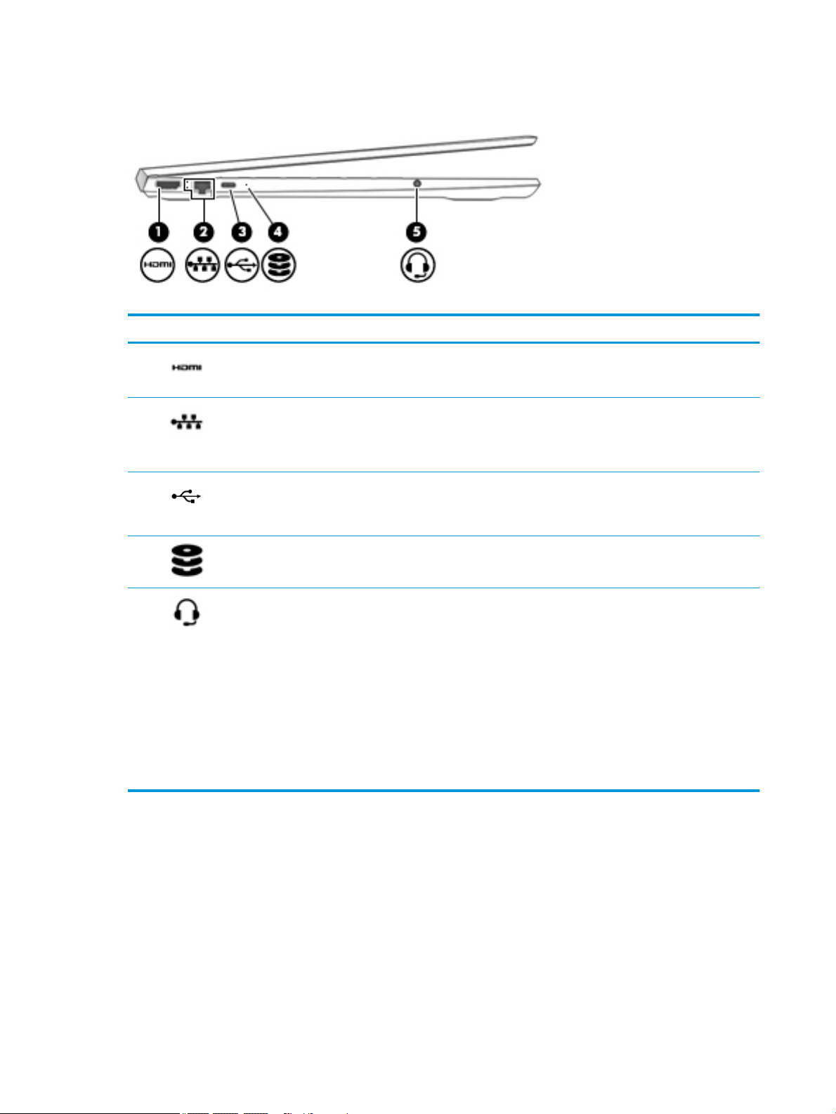
Left side
Table 2-2 Left-side components and their descriptions
Component Description
(1) HDMI port Connects an optional video or audio device, such as a high-denition
(2) RJ-45 (network) jack/status lights Connects a network cable.
(3) USB Type-C port Connects a USB device, such as a cell phone, camera, activity tracker, or
television, any compatible digital or audio component, or a high-speed HighDenition Multimedia Interface (HDMI) device.
● White: The network is connected.
● Amber: Activity is occurring on the network.
smartwatch, and provides data transfer.
NOTE: Cables and/or adapters (purchased separately) may be required.
(4) Drive light ● Blinking white: The hard drive is being accessed.
● Amber: HP 3D DriveGuard has temporarily parked the hard drive.
(5) Audio-out (headphone)/Audio-in
(microphone) combo jack
Connects optional powered stereo speakers, headphones, earbuds, a headset,
or a television audio cable. Also connects an optional headset microphone.
This jack does not support optional standalone microphones.
WARNING! To reduce the risk of personal injury, adjust the volume before
putting on headphones, earbuds, or a headset. For additional safety
information, refer to the Regulatory, Safety, and Environmental Notices.
To access this guide:
▲ Select the Start button, select HP Help and Support, and then select HP
Documentation.
NOTE: When a device is connected to the jack, the computer speakers are
disabled.
8 Chapter 2 Getting to know your computer
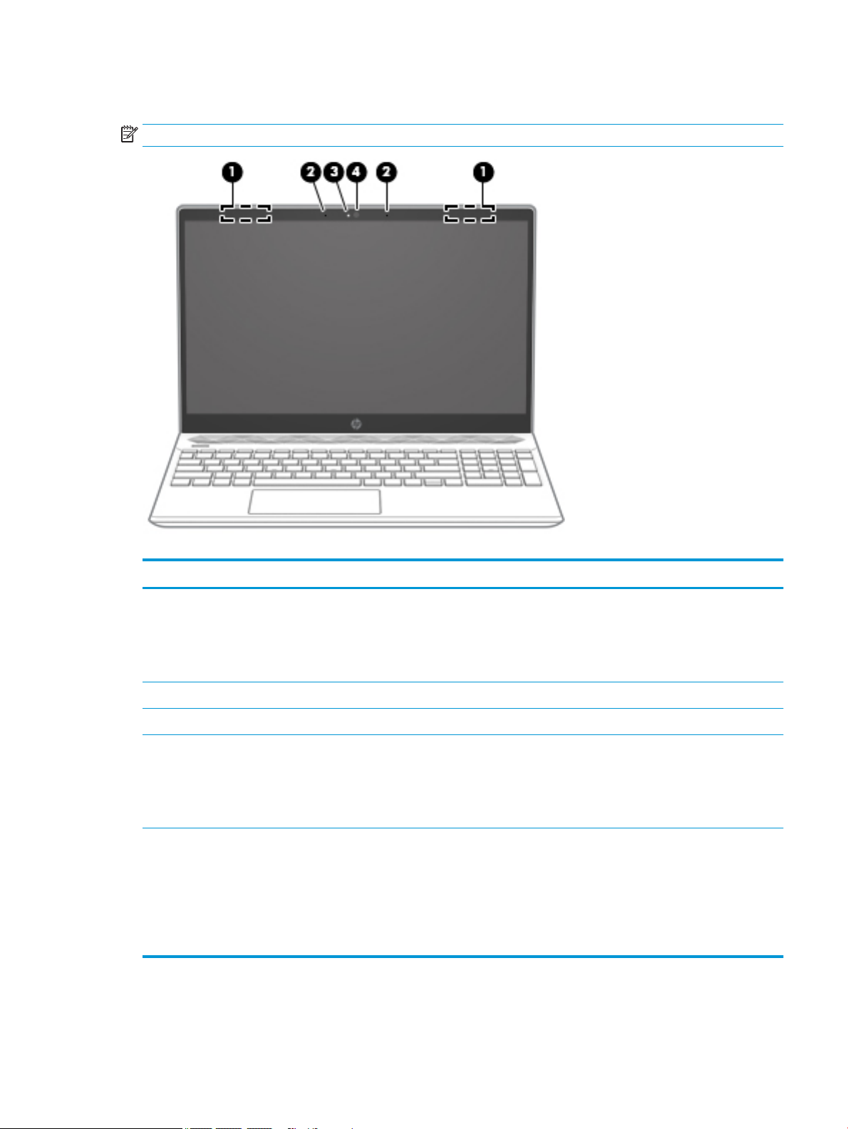
Display
NOTE: Refer to the illustration that most closely matches your computer.
Table 2-3 Display components and their descriptions
Component Description
(1) WLAN antenna(s)* Send and receive wireless signals to communicate with wireless local
area networks (WLANs).
NOTE: Depending on the model, your computer may have one or
two wireless antennas. If your computer has a single antenna, it will
be located on the right side.
(2) Internal microphones Record sound.
(3) Camera light On: The camera is in use.
(4) Camera Allows you to video chat, record video, and record still images. Some
cameras also allow a facial recognition logon to Windows, instead of
a password logon. .
NOTE: Camera functions vary depending on the camera hardware
and software installed on your product.
*The antennas are not visible from the outside of the computer. For optimal transmission, keep the areas immediately around the
antennas free from obstructions.
For wireless regulatory notices, see the section of the Regulatory, Safety, and Environmental Notices that applies to your country or
region.
To access this guide:
▲ Select the Start button, select HP Help and Support, and then select HP Documentation.
Display 9
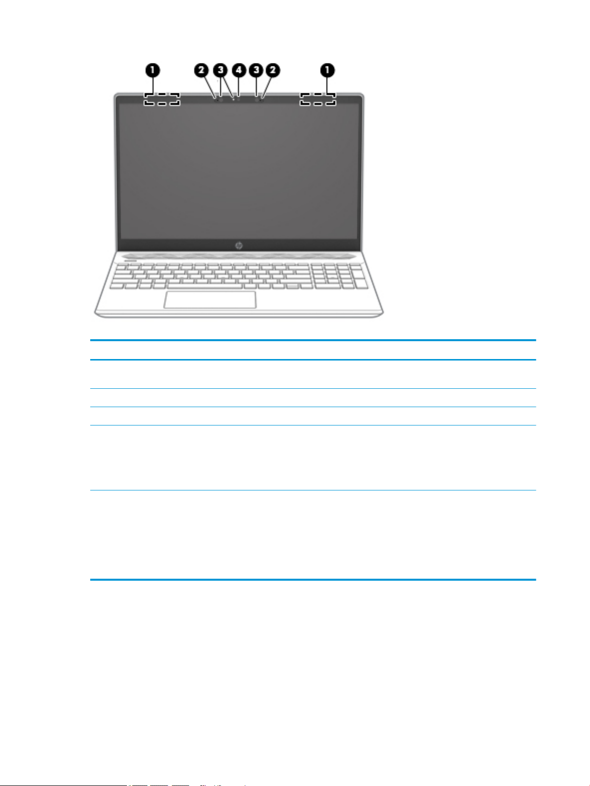
Table 2-4 Display components and their descriptions
Component Description
(1) WLAN antennas* Send and receive wireless signals to communicate with wireless local
area networks (WLANs).
(2) Internal microphones Record sound.
(3) Camera light(s) On: One or more cameras are in use.
(4) Camera(s) Allow(s) you to video chat, record video, and record still images. .
Some cameras also allow a facial recognition logon to Windows,
instead of a password logon..
NOTE: Camera functions vary depending on the camera hardware
and software installed on your product.
*The antennas are not visible from the outside of the computer. For optimal transmission, keep the areas immediately around the
antennas free from obstructions.
For wireless regulatory notices, see the section of the Regulatory, Safety, and Environmental Notices that applies to your country or
region.
To access this guide:
▲ Select the Start button, select HP Help and Support, and then select HP Documentation.
10 Chapter 2 Getting to know your computer
Keyboard area
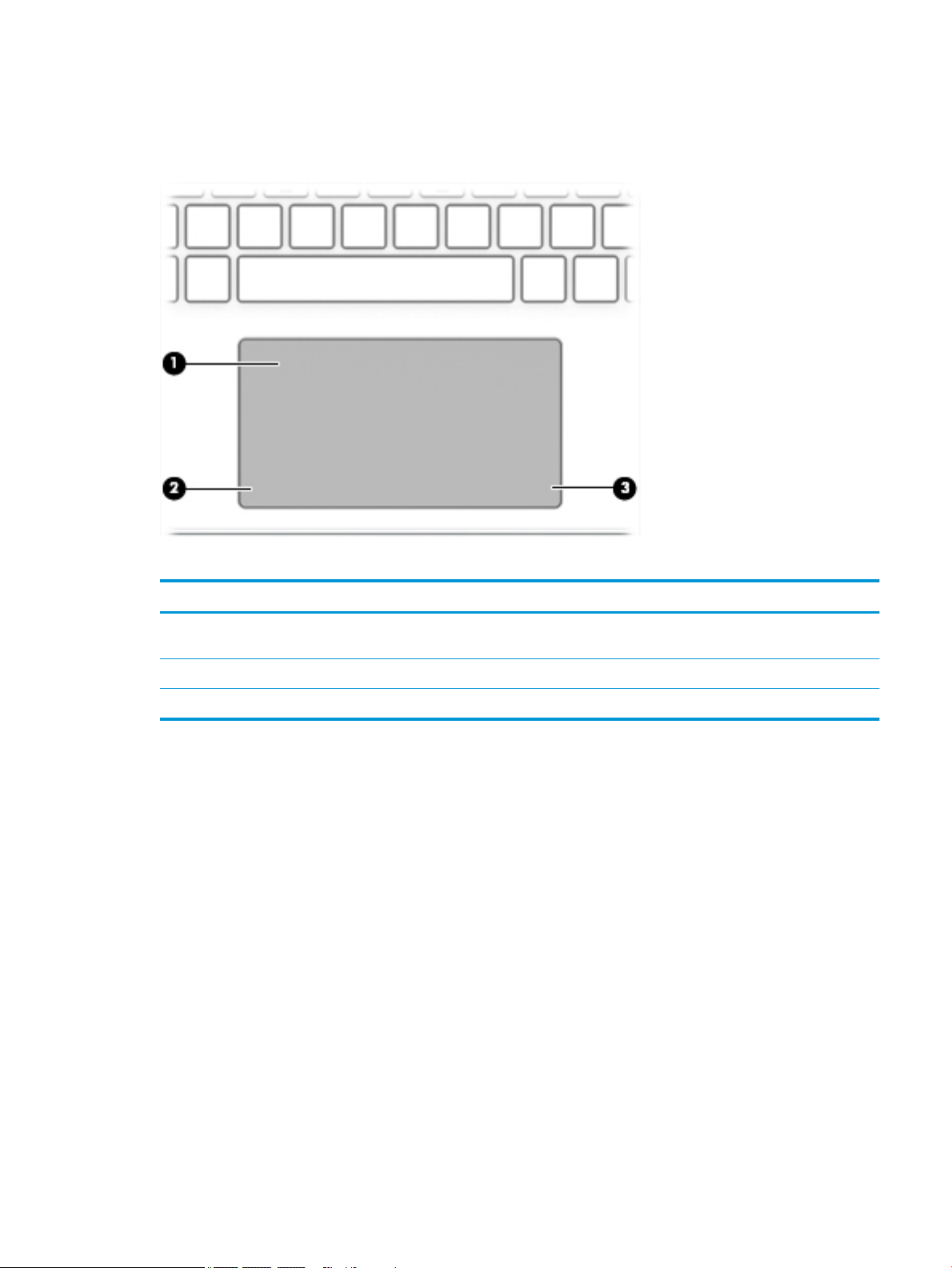
TouchPad
Table 2-5 TouchPad components and their descriptions
Component Description
(1) TouchPad zone Reads your nger gestures to move the pointer or activate items
on the screen.
(2) Left TouchPad button Functions like the left button on an external mouse.
(3) Right TouchPad button Functions like the right button on an external mouse.
Keyboard area 11
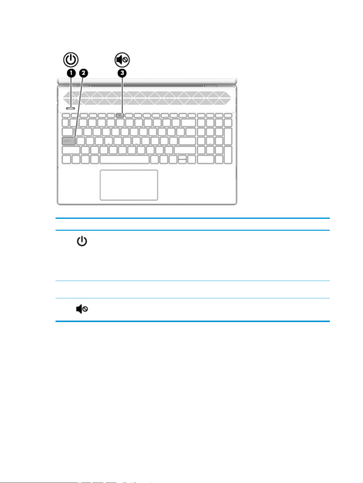
Lights
Table 2-6 Lights and their descriptions
Component Description
(1) Power light ● On: The computer is on.
● Blinking: The computer is in the Sleep state, a power-
saving state. The computer shuts o power to the display
and other unneeded components.
● O: The computer is o or in Hibernation. Hibernation is a
power-saving state that uses the least amount of power.
(2) Caps lock light On: Caps lock is on, which switches the key input to all capital
letters.
(3) Mute light ● On: Computer sound is o.
● O: Computer sound is on.
12 Chapter 2 Getting to know your computer
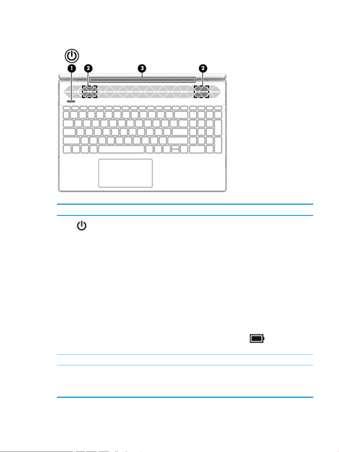
Power button, speakers, and vent
Table 2-7 Power button, speakers, and vent and their descriptions
Component Description
(1) Power button ● When the computer is o, press the button to turn on the
computer.
● When the computer is on, press the button briey to
initiate Sleep.
● When the computer is in the Sleep state, press the button
briey to exit Sleep (select products only).
● When the computer is in Hibernation, press the button
briey to exit Hibernation.
CAUTION: Pressing and holding down the power button results
in the loss of unsaved information.
If the computer has stopped responding and shutdown
procedures are ineective, press and hold the power button
down for at least 5 seconds to turn o the computer.
To learn more about your power settings, see your power
options:
▲ Right-click the Power icon , and then select Power
Options.
(2) Speakers Produce sound.
(3) Vent Enables air ow to cool internal components.
NOTE: The computer fan starts up automatically to cool
internal components and prevent overheating. It is normal for
the internal fan to cycloe on and o during routine operation.
Keyboard area 13
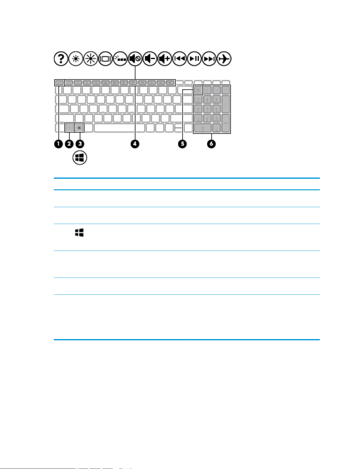
Special keys
Table 2-8 Special keys and their descriptions
Component Description
(1) esc key Displays system information when pressed in combination with
(2) fn key Executes specic functions when pressed in combination with
the fn key.
another key.
(3) Windows key Opens the Start menu.
NOTE: Pressing the Windows key again will close the Start
menu.
(4) Action keys Execute frequently used system functions.
NOTE: On select products, the f5 action key turns the keyboard
backlight feature o or on.
(5) num lock key Alternates between the navigational and numeric functions on
the integrated numeric keypad.
(6) Integrated numeric keypad A separate keypad to the right of the alphabet keyboard. When
num lock is pressed, the keypad can be used like an external
numeric keypad.
NOTE: If the keypad function is active when the computer is
turned o, that function is reinstated when the computer is
turned back on.
14 Chapter 2 Getting to know your computer
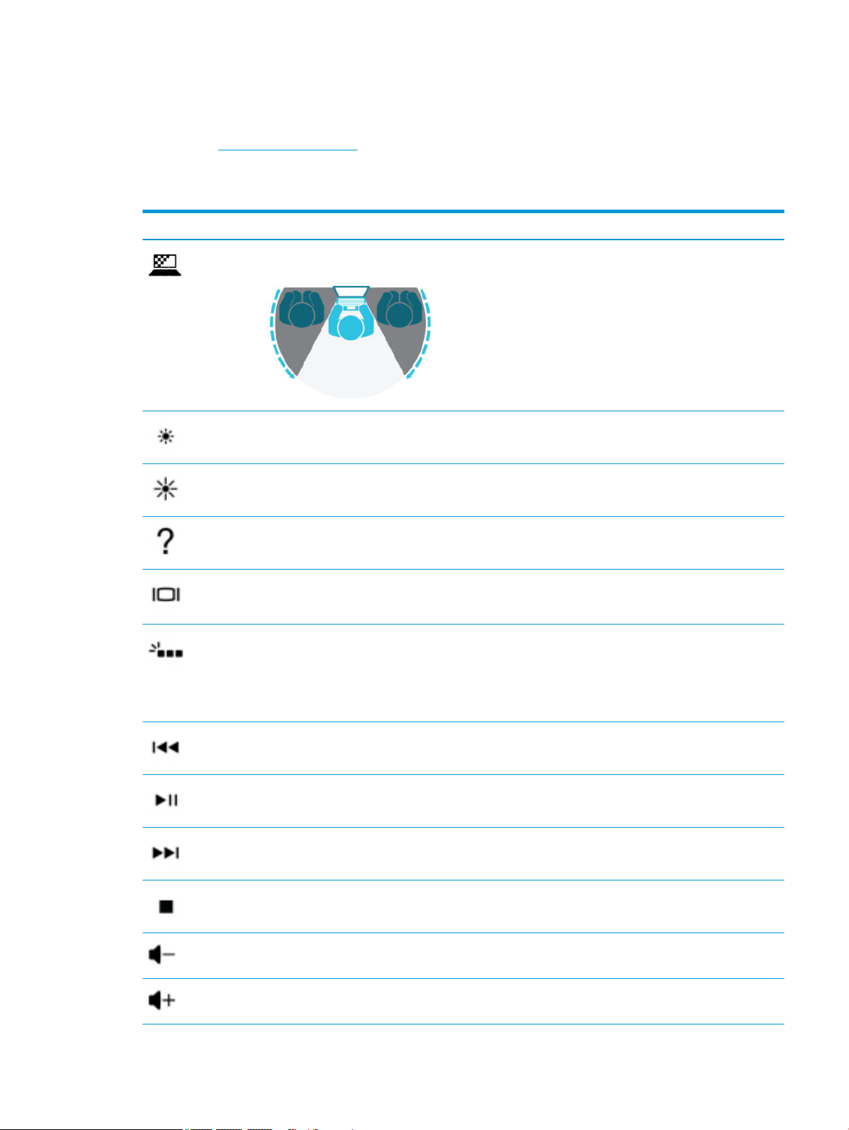
Action keys
An action key performs the function indicated by the icon on the key. To determine which keys are on your
product, see Special keys on page 14.
▲ To use an action key, press and hold the key.
Table 2-9 Action keys and their descriptions
Icon Description
Helps prevent side-angle viewing from onlookers. If needed, decrease or increase brightness for well-lit or
darker environments. Press the key again to turn o the privacy screen.
Decreases the screen brightness incrementally as long as you hold down the key.
Increases the screen brightness incrementally as long as you hold down the key.
Opens the “How to get help in Windows 10” webpage.
Switches the screen image between display devices connected to the system. For example, if a monitor is
connected to the computer, repeatedly pressing this key alternates the screen image from the computer
display to the monitor display to a simultaneous display on both the computer and the monitor.
Turns the keyboard backlight o or on. On select products, you can adjust the brightness of the keyboard
backlight. Press the key repeatedly to adjust the brightness from high (when you rst start up the computer),
to low, to o. After you adjust the keyboard backlight setting, the backlight will revert to your previous
setting each time you turn on the computer. The keyboard backlight will turn o after 30 seconds of
inactivity. To turn the keyboard backlight back on, press any key or tap the TouchPad (select products only).
To conserve battery power, turn o this feature.
Plays the previous track of an audio CD or the previous section of a DVD or a Blu-ray Disc (BD).
Starts, pauses, or resumes playback of an audio CD, a DVD, or a BD.
Plays the next track of an audio CD or the next section of a DVD or a BD.
Stops audio or video playback of a CD, a DVD, or a BD.
Decreases speaker volume incrementally while you hold down the key.
Increases speaker volume incrementally while you hold down the key.
Keyboard area 15
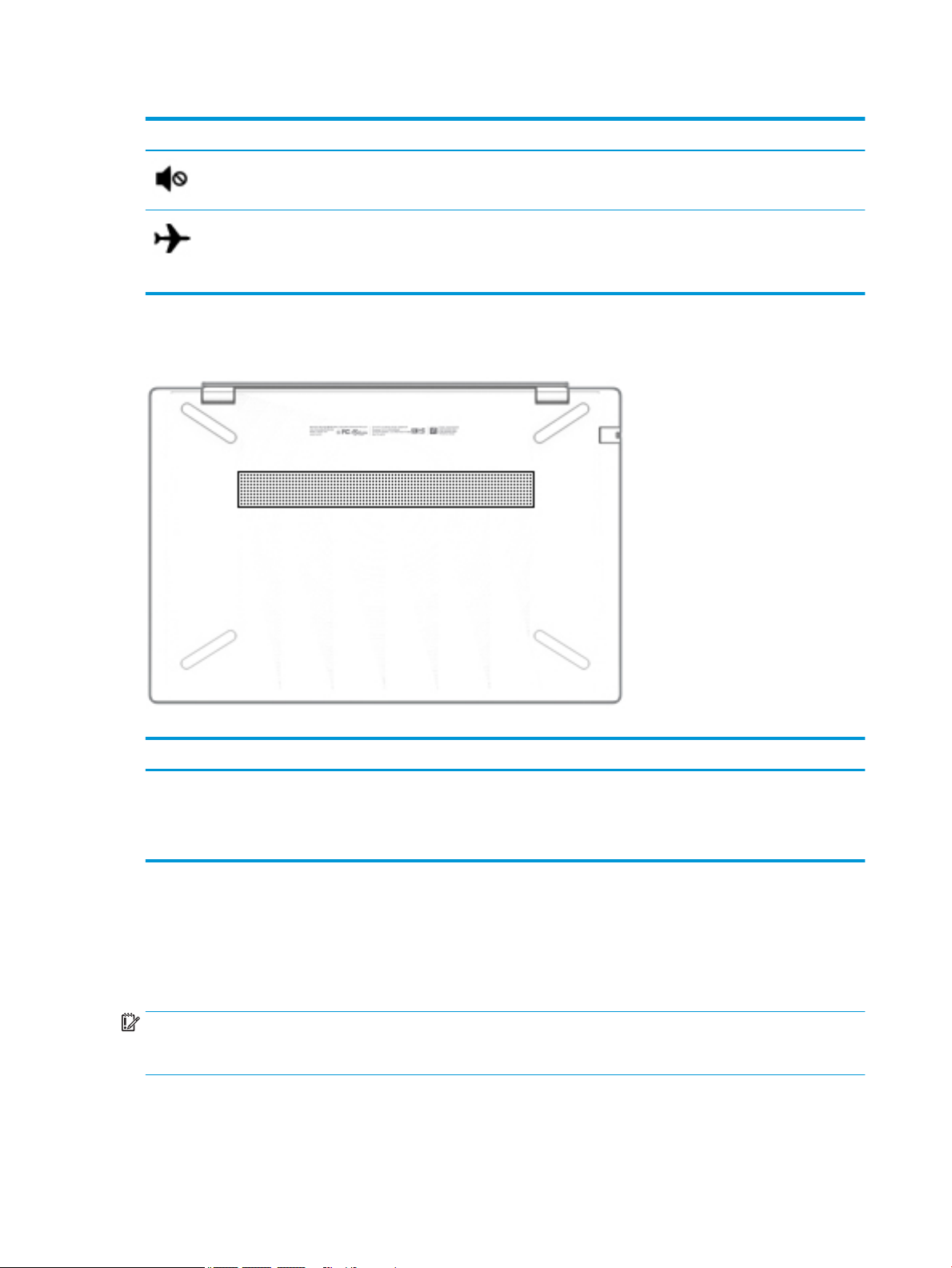
Table 2-9 Action keys and their descriptions (continued)
Icon Description
Bottom
Mutes or restores speaker sound.
Turns the airplane mode and wireless feature on or o.
NOTE: The airplane mode key is also referred to as the wireless button.
NOTE: A wireless network must be set up before a wireless connection is possible.
Labels
Table 2-10 Bottom components and their descriptions
Component Description
Vent Enables airow to cool internal components.
NOTE: The computer fan starts up automatically to cool internal
components and prevent overheating. It is normal for the internal fan to
cycle on and o during routine operation.
The labels axed to the computer provide information you may need when you troubleshoot system
problems or travel internationally with the computer. Labels may be in paper form or imprinted on the
product.
IMPORTANT: Check the following locations for the labels described in this section: the bottom of the
computer, inside the battery bay, under the service door, on the back of the display, or on the bottom of a
tablet kickstand.
● Service label—Provides important information to identify your computer. When contacting support, you
may be asked for the serial number, the product number, or the model number. Locate this information
before you contact support.
16 Chapter 2 Getting to know your computer
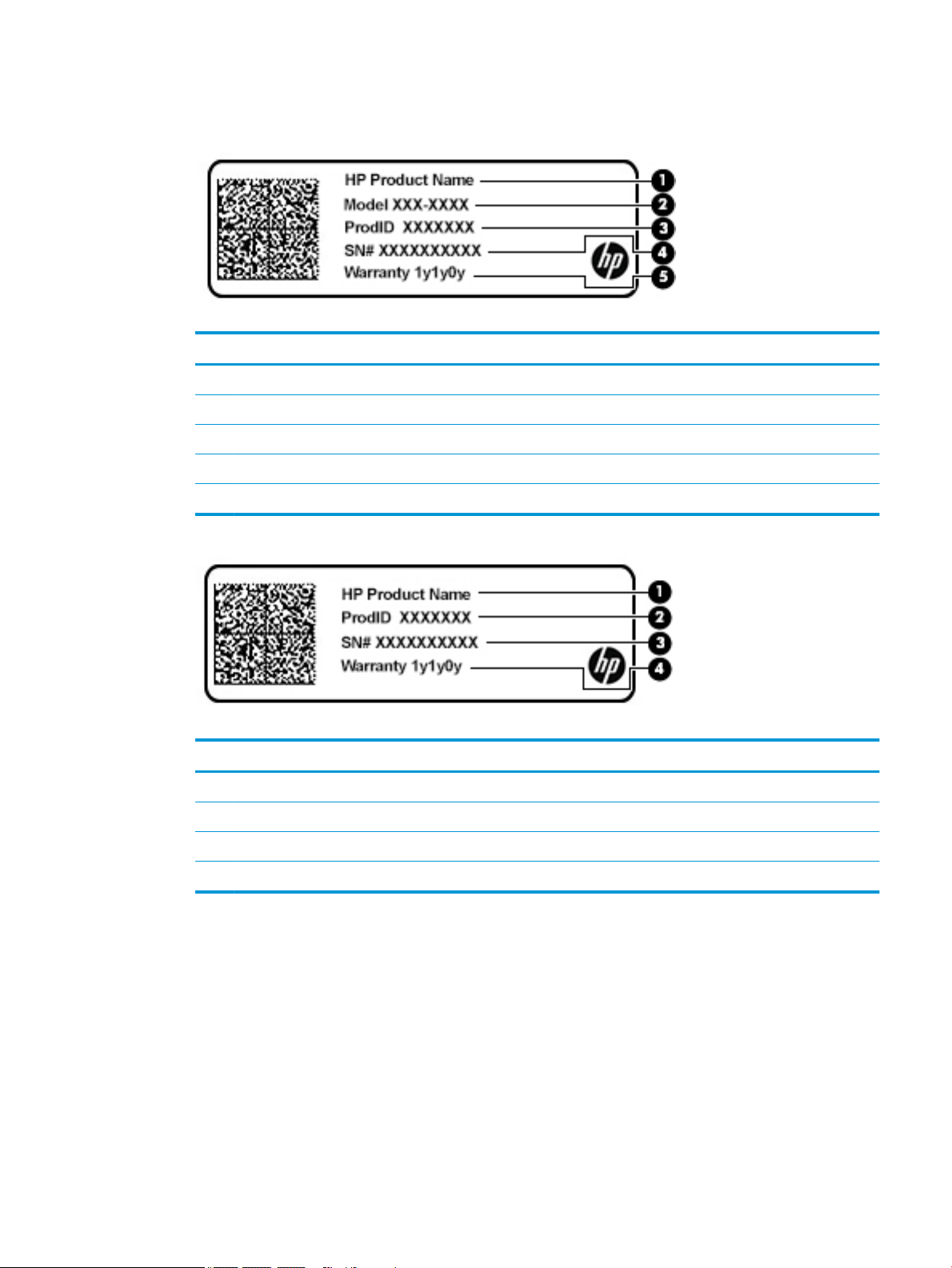
Your service label will resemble one of the examples shown below. Refer to the illustration that most
closely matches the service label on your computer.
Table 2-11 Service label components
Component
(1) HP product name
(2) Model number
(3) Product ID
(4) Serial number
(5) Warranty period
Table 2-12 Service label components
Component
(1) HP product name
(2) Product ID
(3) Serial number
(4) Warranty period
● Regulatory label(s)—Provide(s) regulatory information about the computer.
● Wireless certication label(s)—Provide(s) information about optional wireless devices and the approval
markings for the countries or regions in which the devices have been approved for use.
Labels 17
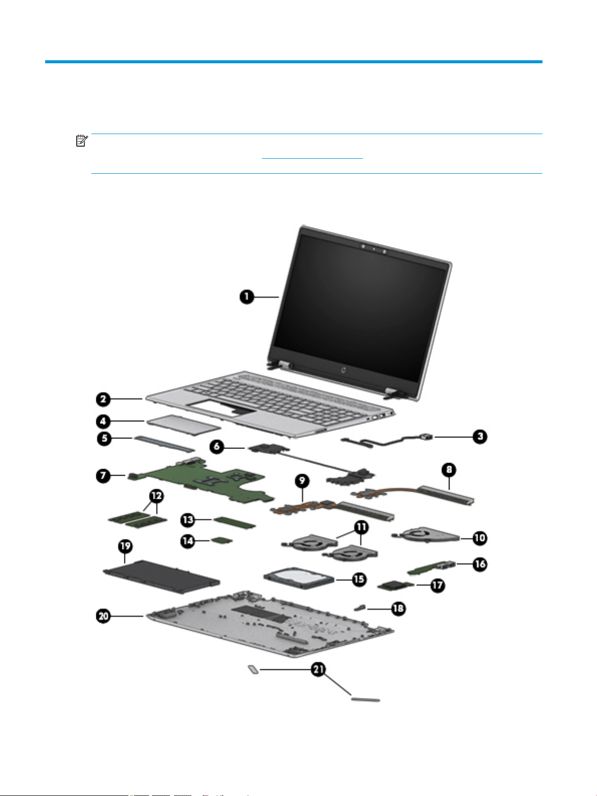
3 Illustrated parts catalog
NOTE: HP continually improves and changes product parts. For complete and current information on
supported parts for your computer, go to http://partsurfer.hp.com, select your country or region, and then
follow the on-screen instructions.
Computer components
18 Chapter 3 Illustrated parts catalog

Table 3-1 Computer major components and their descriptions
Item Component Spare part number
(1) Display assembly: The display assembly is spared at the subcomponent level only. For more display assembly spare part
(2) Top cover with keyboard:
Natural silver, backlit L24752-xx1
Natural silver, no backlight L24753-xx1
Pale gold, backlit L24754-xx1
Pale gold, no backlight L24755-xx1
Cloud blue, backlight L49391-xx1
Cloud blue, no backlight L49392-xx1
Luminous gold, backlight L49393-xx1
Luminous gold, no backlight L49394-xx1
Top cover with keyboard (on models equipped with GTX graphics):
Natural silver, backlit L35339–xx1
Natural silver, no backlight L35340–xx1
(3) Power connector cable:
information, see Display assembly components on page 23.
810327-006
Power connector cable EMI tape is available in the Miscellaneous Parts Kit using spare part
number L28015-001.
Power connector cable in models equipped with GTX graphics L45827-001
(4) TouchPad:
NOTE: The TouchPad cable is available using spare part number L23893-001.
Natural silver L24934-001
Pale gold L24933-001
Fog blue L51805-001
Warm gold L51806-001
(5) TouchPad bracket L23892-001
(6) Speakers (includes cable) L23900-001
Speakers (on models equipped with GTX graphics) (include cable) L41588-001
(7) System board (includes processor and replacement thermal material):
System board for use in models with discrete graphics equipped with the following processors:
Intel Core i7-8565U processor and 4 GB of MX 250 discrete video memory L50260-xx1
Intel Core i7-8565U processor and 2 GB of MX 250 discrete video memory L50259-xx1
Intel Core i7-8565U processor and 4 GB of GTX 1050 discrete video memory L34171-xx1
Intel Core i7-8565U processor and 4 GB of GeForce MX150 discrete video memory L34176-xx1
Intel Core i7-8565U processor and 2 GB of GeForce MX150 discrete video memory L34175-xx1
Computer components 19

Table 3-1 Computer major components and their descriptions (continued)
Item Component Spare part number
Intel Core i7-8565U processor with 3 GB of GTX discrete video memory L46518-xx1
Intel Core i7-8565U processor with 4 GB of GTX 1050Ti discrete video memory L34172-xx1
Intel Core i7-8550U processor and 4 GB of GeForce MX150 discrete video memory L22820-xx1
Intel Core i7-8550U processor and 2 GB of GeForce MX150 discrete video memory L22817-xx1
Intel Core i7-8550U processor and 2 GB of GeForce MX130 discrete video memory L22814-xx1
Intel Core i5-8265U processor and 2 GB of GeForce MX250 discrete video memory L50258-xx1
Intel Core i5-8265U processor and 2 GB of GTX 1050 discrete video memory L34170-xx1
Intel Core i5-8265U processor and 2 GB of GeForce MX130 discrete video memory L34173-xx1
Intel Core i5-8265U processor and 2 GB of GeForce MX150 discrete video memory L34174-xx1
Intel Core i5-8265U processor with 4 GB of GTX 1050Ti discrete video memory L44879-xx1
Intel Core i5-8265U processor with GTX and 3 GB of GeForce MX150 discrete video memory L52957-xx1
Intel Core i5-8250U processor and 4 GB of GeForce MX150 discrete video memory L22818-xx1
Intel Core i5-8250U processor and 2 GB of GeForce MX150 discrete video memory L22815-xx1
Intel Core i5-8250U processor and 2 GB of GeForce MX130 discrete video memory L22813-xx1
Intel Core i7-7500U processor and 4 GB of GeForce MX150 discrete video memory L22819-xx1
Intel Core i7-7500U processor and 2 GB of GeForce MX150 discrete video memory L22816-xx1
Intel Core i3-8130U processor and 2 GB of GeForce MX150 discrete video memory L37245-xx1
System board for use in models with UMA graphics equipped with the following processors:
Intel Core i7-8565U processor L50262-xx1
Intel Core i7-8550U processor L22822-xx1
Intel Core i5-8250U processor L22821-xx1
Intel Core i3-8145U processor L50261-xx1
Intel Core i3-8130U processor L22824-xx1
Intel Core i5-8265U processor L34169-xx1
Intel Pentium 4415U processor L22823-xx1
(8) Heat sink, UMA graphics (not pictured) for use only on computer models equipped with Intel Core
i7-8550U/i5-8250U processors (includes replacement thermal material)
Heat sink, UMA graphics (not pictured) for use only on computer models equipped with Intel Core
i7-7500U/Pentium 4415U processors (includes replacement thermal material)
Heat sink, GTX discrete graphics (not illustrated) (includes replacement thermal material) L35251-001
(9) Heat sink, discrete graphics (includes replacement thermal material) L23897-001
L23898-001
L23899-001
(10) Fan for use in models with UMA graphics memory L27902-001
(11) Fan for use in models with discrete graphics memory L23895-001
Fan for use in models with discrete graphics memory (on models equipped with GTX graphics) L35338-001
20 Chapter 3 Illustrated parts catalog

Table 3-1 Computer major components and their descriptions (continued)
Item Component Spare part number
(12) Memory modules (2, DDR4-2400, 1.2-V):
8 GB 862398-855
4 GB 862397-855
2 GB 864271-855
(13) Solid-state drive (2280 M.2):
512 GB, PCIe L25329-001
512 GB, PCIe, TLC L56705-001
256 GB, SATA-3, TLC L25327-001
256 GB, PCIe L25328-001
128 GB, SATA-3, TLC L25326-001
Optane memory module, 16 GB, PCIe L27309-001
(14) WLAN module
Intel Dual Band Wireless-AC 7265 802.11ac 2 × 2 Wi-Fi + Bluetooth 4.2 Combo Adapter (non-vPro) 901229-855
Intel Dual Band Wireless-AC 3168 802.11ac 1 × 1 Wi-Fi + Bluetooth 4.2 Combo Adapter (non-vPro) 863934-855
Realtek RTL8822BE 802.11ac 2 × 2 Wi-Fi + Bluetooth 4.2 Combo Adapter (MU-MIMO supported) 924813-855
Realtek RTL8821CE 802.11ac 1 × 1 Wi-Fi + Bluetooth 4.2 Combo Adapter (MU-MIMO supported) L17365-005
Realtek RTL8723DE-CG 802.11bgn 1 × 1 Wi-Fi + Bluetooth 4.2 Combo Adapter L21480-005
Intel Dual Band Wireless-AC + Bluetooth 5 Combo Adapter (non-vPro) L22634-005
Intel Dual Band Wireless-AC 9461 802.11ac 1 × 1 Wi-Fi + Bluetooth 5 Combo Adapter (non-vPro) L25889-005
(15) Hard drive (SATA, 7.0-mm; does not include hard drive bracket or hard drive cable):
2 TB, 5400-rpm 912487-855
1 TB, 5400-rpm 762990-005
500 GB, 5400-rpm 778186-005
NOTE: Hard drive brackets are available using spare part number L19469-001. The hard drive cable is available using
spare part number L23889-001
(16) USB board (select products only)
NOTE: The USB board cable is available using spare part number L23901-001.
(17) Memory card reader board
NOTE: The memory card reader board cable is available using spare part number L23891-001
and L41586-001 on models equipped with GTX graphics
Memory card reader board (on models equipped with GTX graphics) L41585-001
L23896-001
L23890-001
(18) Lock bracket L23902-001
(19) Battery
4-cell 68 Whr L32654-005
Computer components 21

Table 3-1 Computer major components and their descriptions (continued)
Item Component Spare part number
3-cell, 41 Whr L11119-855
(20) Bottom cover
Natural silver L23885-001
Natural silver (on models equipped with GTX graphics) L41587-001
Pale gold L23886-001
Fog blue L51801-001
Warm gold L51802-001
(21) Rubber Foot Kit (includes Mylar screw cover):
For use in natural silver models L23887-001
For use in pale gold models L23888-001
For use in fog blue models L51807-001
For use in warm gold models L51808-001
22 Chapter 3 Illustrated parts catalog
 Loading...