

Page 1

User Guide
hp StorageWorks
Network Storage Router M2402
Product Version: 1.0
Third Edition (March 2004)
Part Number: 269782-004
The HP StorageWorks Network Storage Router M2402 provides bi-directional connectivity in
either a Fibre Channel Switched Fabric or a Fibre Channel Arbitrated Loop environment,
supporting Fibre Channel and SCSI devices.
This user guide provides instructional information for installing and configuring the network
storage router.
Page 2

© Copyright 2002-2004 Hewlett-Packard Development Company, L.P.
Hewlett-Packard Company makes no warranty of any kind with regard to this material, including, but not limited to,
the implied warranties of merchantability and fitness for a particular purpose. Hewlett-Packard shall not be liable for
errors contained herein or for incidental or consequential damages in connection with the furnishing, performance,
or use of this material.
This document contains proprietary information, which is protected by copyright. No part of this document may be
photocopied, reproduced, or translated into another language without the prior written consent of Hewlett-Packard.
The information contained in this document is subject to change without notice. The only warranties for HP products
and services are set forth in the express warranty statements accompanying such products and services. Nothing
herein should be construed as constituting an additional warranty. HP shall not be liable for technical or editorial
errors or omissions contained herein.
Compaq Computer Corporation is a wholly-owned subsidiary of Hewlett-Packard Company.
Adobe® and Acrobat® are trademarks of Adobe Systems Incorporated.
Microsoft®, MS-DOS®, MS Windows®, Windows®, and Windows NT® are U.S. registered trademarks of
Microsoft Corporation.
Hewlett-Packard Company shall not be liable for technical or editorial errors or omissions contained herein. The
information is provided “as is” without warranty of any kind and is subject to change without notice. The warranties
for Hewlett-Packard Company products are set forth in the express limited warranty statements for such products.
Nothing herein should be construed as constituting an additional warranty.
Network Storage Router M2402 User Guide
Third Edition (March 2004)
Part Number: 269782-004
Page 3

Contents
Contents
About this Guide . . . . . . . . . . . . . . . . . . . . . . . . . . . . . . . . . . . . . . . . . . . . . . . . . . . . .17
Conventions . . . . . . . . . . . . . . . . . . . . . . . . . . . . . . . . . . . . . . . . . . . . . . . . . . . . . . . . . . . . . . 18
Document Conventions . . . . . . . . . . . . . . . . . . . . . . . . . . . . . . . . . . . . . . . . . . . . . . . . . . 18
Text Symbols . . . . . . . . . . . . . . . . . . . . . . . . . . . . . . . . . . . . . . . . . . . . . . . . . . . . . . . . . . 18
Equipment Symbols. . . . . . . . . . . . . . . . . . . . . . . . . . . . . . . . . . . . . . . . . . . . . . . . . . . . . 19
Rack Stability . . . . . . . . . . . . . . . . . . . . . . . . . . . . . . . . . . . . . . . . . . . . . . . . . . . . . . . . . . . . . 21
Getting Help . . . . . . . . . . . . . . . . . . . . . . . . . . . . . . . . . . . . . . . . . . . . . . . . . . . . . . . . . . . . . . 22
HP Technical Support . . . . . . . . . . . . . . . . . . . . . . . . . . . . . . . . . . . . . . . . . . . . . . . . . . . 22
HP Storage Website . . . . . . . . . . . . . . . . . . . . . . . . . . . . . . . . . . . . . . . . . . . . . . . . . . . . . 22
HP Authorized Reseller . . . . . . . . . . . . . . . . . . . . . . . . . . . . . . . . . . . . . . . . . . . . . . . . . . 22
1 Introduction . . . . . . . . . . . . . . . . . . . . . . . . . . . . . . . . . . . . . . . . . . . . . . . . . . . . . .23
External Features Overview . . . . . . . . . . . . . . . . . . . . . . . . . . . . . . . . . . . . . . . . . . . . . . . . . . 24
Power Module . . . . . . . . . . . . . . . . . . . . . . . . . . . . . . . . . . . . . . . . . . . . . . . . . . . . . . . . . 25
Fan Module . . . . . . . . . . . . . . . . . . . . . . . . . . . . . . . . . . . . . . . . . . . . . . . . . . . . . . . . . . . 25
Fibre Channel Modules . . . . . . . . . . . . . . . . . . . . . . . . . . . . . . . . . . . . . . . . . . . . . . . . . . 26
SCSI Modules . . . . . . . . . . . . . . . . . . . . . . . . . . . . . . . . . . . . . . . . . . . . . . . . . . . . . . . . . 27
Ethernet Port/Standby Power Button. . . . . . . . . . . . . . . . . . . . . . . . . . . . . . . . . . . . . . . . 27
Serial Port. . . . . . . . . . . . . . . . . . . . . . . . . . . . . . . . . . . . . . . . . . . . . . . . . . . . . . . . . . . . . 28
Functional Overview . . . . . . . . . . . . . . . . . . . . . . . . . . . . . . . . . . . . . . . . . . . . . . . . . . . . . . . 29
Fibre Channel to SCSI Protocol Process . . . . . . . . . . . . . . . . . . . . . . . . . . . . . . . . . . . . . 30
SCSI to Fibre Channel Protocol Process . . . . . . . . . . . . . . . . . . . . . . . . . . . . . . . . . . . . . 31
LAN-free Backup and Restore. . . . . . . . . . . . . . . . . . . . . . . . . . . . . . . . . . . . . . . . . . . . . 32
Server-free Data Movement. . . . . . . . . . . . . . . . . . . . . . . . . . . . . . . . . . . . . . . . . . . . . . . 33
Physical Requirements. . . . . . . . . . . . . . . . . . . . . . . . . . . . . . . . . . . . . . . . . . . . . . . . . . . 34
Contents
1Network Storage Router M2402 User Guide
Page 4

Contents
2 Installation . . . . . . . . . . . . . . . . . . . . . . . . . . . . . . . . . . . . . . . . . . . . . . . . . . . . . . .35
Selecting a Location . . . . . . . . . . . . . . . . . . . . . . . . . . . . . . . . . . . . . . . . . . . . . . . . . . . . . . . . 36
Unpacking the Box. . . . . . . . . . . . . . . . . . . . . . . . . . . . . . . . . . . . . . . . . . . . . . . . . . . . . . . . . 36
Placing the Router on a Desktop . . . . . . . . . . . . . . . . . . . . . . . . . . . . . . . . . . . . . . . . . . . . . . 36
Installing the Router in a Rack. . . . . . . . . . . . . . . . . . . . . . . . . . . . . . . . . . . . . . . . . . . . . . . . 37
Connecting the Power Cord . . . . . . . . . . . . . . . . . . . . . . . . . . . . . . . . . . . . . . . . . . . . . . . . . . 42
Connecting the Interfaces. . . . . . . . . . . . . . . . . . . . . . . . . . . . . . . . . . . . . . . . . . . . . . . . . . . . 44
Fibre Channel Connections . . . . . . . . . . . . . . . . . . . . . . . . . . . . . . . . . . . . . . . . . . . . . . . 45
SCSI Connections . . . . . . . . . . . . . . . . . . . . . . . . . . . . . . . . . . . . . . . . . . . . . . . . . . . . . . 48
Ethernet Connections. . . . . . . . . . . . . . . . . . . . . . . . . . . . . . . . . . . . . . . . . . . . . . . . . . . . 50
Serial Port Connections . . . . . . . . . . . . . . . . . . . . . . . . . . . . . . . . . . . . . . . . . . . . . . . . . . 51
Setting up Serial Port Communications. . . . . . . . . . . . . . . . . . . . . . . . . . . . . . . . . . . 52
3 Configuration Overview . . . . . . . . . . . . . . . . . . . . . . . . . . . . . . . . . . . . . . . . . . . . .53
Router Default Settings. . . . . . . . . . . . . . . . . . . . . . . . . . . . . . . . . . . . . . . . . . . . . . . . . . . . . . 54
UI Overview . . . . . . . . . . . . . . . . . . . . . . . . . . . . . . . . . . . . . . . . . . . . . . . . . . . . . . . . . . . . . . 55
Visual Manager . . . . . . . . . . . . . . . . . . . . . . . . . . . . . . . . . . . . . . . . . . . . . . . . . . . . . . . . 55
Serial/Telnet. . . . . . . . . . . . . . . . . . . . . . . . . . . . . . . . . . . . . . . . . . . . . . . . . . . . . . . . . . . 55
FTP. . . . . . . . . . . . . . . . . . . . . . . . . . . . . . . . . . . . . . . . . . . . . . . . . . . . . . . . . . . . . . . . . . 55
Common Configuration Settings . . . . . . . . . . . . . . . . . . . . . . . . . . . . . . . . . . . . . . . . . . . . . . 56
Controller LUN Commands. . . . . . . . . . . . . . . . . . . . . . . . . . . . . . . . . . . . . . . . . . . . . . . 56
SCSI Bus Configuration. . . . . . . . . . . . . . . . . . . . . . . . . . . . . . . . . . . . . . . . . . . . . . . . . . 56
Fibre Channel Port Configuration . . . . . . . . . . . . . . . . . . . . . . . . . . . . . . . . . . . . . . . . . . 57
Fibre Channel Arbitrated Loop Configuration. . . . . . . . . . . . . . . . . . . . . . . . . . . . . . . . . 57
Soft Addressing . . . . . . . . . . . . . . . . . . . . . . . . . . . . . . . . . . . . . . . . . . . . . . . . . . . . . 57
Hard Addressing . . . . . . . . . . . . . . . . . . . . . . . . . . . . . . . . . . . . . . . . . . . . . . . . . . . . 57
Fibre Channel Switched Fabric Configuration . . . . . . . . . . . . . . . . . . . . . . . . . . . . . . . . 58
Discovery Mode. . . . . . . . . . . . . . . . . . . . . . . . . . . . . . . . . . . . . . . . . . . . . . . . . . . . . . . . 58
Host Device Configuration . . . . . . . . . . . . . . . . . . . . . . . . . . . . . . . . . . . . . . . . . . . . . . . 58
Logical Unit Management . . . . . . . . . . . . . . . . . . . . . . . . . . . . . . . . . . . . . . . . . . . . . . . . 59
Indexed Maps . . . . . . . . . . . . . . . . . . . . . . . . . . . . . . . . . . . . . . . . . . . . . . . . . . . . . . 60
Auto Assigned Maps . . . . . . . . . . . . . . . . . . . . . . . . . . . . . . . . . . . . . . . . . . . . . . . . . 60
SCC Maps . . . . . . . . . . . . . . . . . . . . . . . . . . . . . . . . . . . . . . . . . . . . . . . . . . . . . . . . . 60
Buffered Tape Writes. . . . . . . . . . . . . . . . . . . . . . . . . . . . . . . . . . . . . . . . . . . . . . . . . . . . 60
2 Network Storage Router M2402 User Guide
Page 5

Contents
4 Visual Manager User Interface . . . . . . . . . . . . . . . . . . . . . . . . . . . . . . . . . . . . . . . .61
Visual Manager Access . . . . . . . . . . . . . . . . . . . . . . . . . . . . . . . . . . . . . . . . . . . . . . . . . . . . . 63
Visual Manager Best Practices. . . . . . . . . . . . . . . . . . . . . . . . . . . . . . . . . . . . . . . . . . . . . . . . 65
Main Menu . . . . . . . . . . . . . . . . . . . . . . . . . . . . . . . . . . . . . . . . . . . . . . . . . . . . . . . . . . . . . . . 66
System Menu . . . . . . . . . . . . . . . . . . . . . . . . . . . . . . . . . . . . . . . . . . . . . . . . . . . . . . . . . . . . . 69
Serial Configuration. . . . . . . . . . . . . . . . . . . . . . . . . . . . . . . . . . . . . . . . . . . . . . . . . . . . . 70
Network Configuration . . . . . . . . . . . . . . . . . . . . . . . . . . . . . . . . . . . . . . . . . . . . . . . . . . 71
Ethernet Configuration Settings . . . . . . . . . . . . . . . . . . . . . . . . . . . . . . . . . . . . . . . . 72
Ethernet Override Settings. . . . . . . . . . . . . . . . . . . . . . . . . . . . . . . . . . . . . . . . . . . . . 73
SNMP Configuration (not supported) . . . . . . . . . . . . . . . . . . . . . . . . . . . . . . . . . . . . . . . 73
Active Fabric Configuration . . . . . . . . . . . . . . . . . . . . . . . . . . . . . . . . . . . . . . . . . . . . . . 74
User Configuration. . . . . . . . . . . . . . . . . . . . . . . . . . . . . . . . . . . . . . . . . . . . . . . . . . . . . . 76
Real-Time Clock Configuration. . . . . . . . . . . . . . . . . . . . . . . . . . . . . . . . . . . . . . . . . . . . 77
Power Supply Configuration . . . . . . . . . . . . . . . . . . . . . . . . . . . . . . . . . . . . . . . . . . . . . . 78
Reset Menu. . . . . . . . . . . . . . . . . . . . . . . . . . . . . . . . . . . . . . . . . . . . . . . . . . . . . . . . . . . . 79
Modules Menu . . . . . . . . . . . . . . . . . . . . . . . . . . . . . . . . . . . . . . . . . . . . . . . . . . . . . . . . . . . . 80
World Wide Node Name Configuration . . . . . . . . . . . . . . . . . . . . . . . . . . . . . . . . . . . . . 81
Fibre Channel Module Configuration . . . . . . . . . . . . . . . . . . . . . . . . . . . . . . . . . . . . . . . 82
SCSI Module Configuration . . . . . . . . . . . . . . . . . . . . . . . . . . . . . . . . . . . . . . . . . . . . . . 87
Discovery Menu . . . . . . . . . . . . . . . . . . . . . . . . . . . . . . . . . . . . . . . . . . . . . . . . . . . . . . . . . . . 92
Mapping Menu . . . . . . . . . . . . . . . . . . . . . . . . . . . . . . . . . . . . . . . . . . . . . . . . . . . . . . . . . . . . 93
Fibre Channel and SCSI Common Mapping Tasks. . . . . . . . . . . . . . . . . . . . . . . . . . . . . 94
Fibre Channel Mapping Tasks. . . . . . . . . . . . . . . . . . . . . . . . . . . . . . . . . . . . . . . . . . . . . 95
Viewing and Changing Fibre Channel Host Information . . . . . . . . . . . . . . . . . . . . . 96
Viewing and Changing Fibre Channel Map Information . . . . . . . . . . . . . . . . . . . . . 97
SCSI Mapping Tasks . . . . . . . . . . . . . . . . . . . . . . . . . . . . . . . . . . . . . . . . . . . . . . . . . . . . 99
Viewing and Changing SCSI Host Information . . . . . . . . . . . . . . . . . . . . . . . . . . . . 99
Viewing and Changing SCSI Map Information . . . . . . . . . . . . . . . . . . . . . . . . . . . 100
Statistics Menu . . . . . . . . . . . . . . . . . . . . . . . . . . . . . . . . . . . . . . . . . . . . . . . . . . . . . . . . . . . 103
Utilities Menu. . . . . . . . . . . . . . . . . . . . . . . . . . . . . . . . . . . . . . . . . . . . . . . . . . . . . . . . . . . . 104
Beacon Mode Configuration . . . . . . . . . . . . . . . . . . . . . . . . . . . . . . . . . . . . . . . . . . . . . 105
FTP Utility Access. . . . . . . . . . . . . . . . . . . . . . . . . . . . . . . . . . . . . . . . . . . . . . . . . . . . . 106
Trace Settings Configuration . . . . . . . . . . . . . . . . . . . . . . . . . . . . . . . . . . . . . . . . . . . . . . . . 108
Current, Previous, and Last Assert Trace Displays . . . . . . . . . . . . . . . . . . . . . . . . . . . . 110
Clear Current Traces and Clear Assert Traces. . . . . . . . . . . . . . . . . . . . . . . . . . . . . . . . 111
Event Log Configuration . . . . . . . . . . . . . . . . . . . . . . . . . . . . . . . . . . . . . . . . . . . . . . . . 112
Event Log Display . . . . . . . . . . . . . . . . . . . . . . . . . . . . . . . . . . . . . . . . . . . . . . . . . . . . . 113
Clear Event Log . . . . . . . . . . . . . . . . . . . . . . . . . . . . . . . . . . . . . . . . . . . . . . . . . . . . . . . 114
3Network Storage Router M2402 User Guide
Page 6

Contents
Report Menu. . . . . . . . . . . . . . . . . . . . . . . . . . . . . . . . . . . . . . . . . . . . . . . . . . . . . . . . . . . . . 115
Reboot Option. . . . . . . . . . . . . . . . . . . . . . . . . . . . . . . . . . . . . . . . . . . . . . . . . . . . . . . . . . . . 116
5 Serial/Telnet User Interface . . . . . . . . . . . . . . . . . . . . . . . . . . . . . . . . . . . . . . . . . .117
Telnet UI Access. . . . . . . . . . . . . . . . . . . . . . . . . . . . . . . . . . . . . . . . . . . . . . . . . . . . . . . . . . 119
Serial UI Access . . . . . . . . . . . . . . . . . . . . . . . . . . . . . . . . . . . . . . . . . . . . . . . . . . . . . . . . . . 120
Power up Messages. . . . . . . . . . . . . . . . . . . . . . . . . . . . . . . . . . . . . . . . . . . . . . . . . . . . . . . . 120
Serial/Telnet UI Main Menu. . . . . . . . . . . . . . . . . . . . . . . . . . . . . . . . . . . . . . . . . . . . . . . . . 121
Configuration Menu . . . . . . . . . . . . . . . . . . . . . . . . . . . . . . . . . . . . . . . . . . . . . . . . . . . . . . . 122
Baud Rate Configuration . . . . . . . . . . . . . . . . . . . . . . . . . . . . . . . . . . . . . . . . . . . . . . . . . . . 124
Ethernet Configuration . . . . . . . . . . . . . . . . . . . . . . . . . . . . . . . . . . . . . . . . . . . . . . . . . . . . . 125
World Wide Node Name Configuration. . . . . . . . . . . . . . . . . . . . . . . . . . . . . . . . . . . . . . . . 128
Modules Configuration. . . . . . . . . . . . . . . . . . . . . . . . . . . . . . . . . . . . . . . . . . . . . . . . . . . . . 129
Configuring Fibre Channel Modules . . . . . . . . . . . . . . . . . . . . . . . . . . . . . . . . . . . . . . . 130
Configuring SCSI Modules . . . . . . . . . . . . . . . . . . . . . . . . . . . . . . . . . . . . . . . . . . . . . . 134
Device Mapping . . . . . . . . . . . . . . . . . . . . . . . . . . . . . . . . . . . . . . . . . . . . . . . . . . . . . . . . . . 138
Changing to the Next Port or Bus . . . . . . . . . . . . . . . . . . . . . . . . . . . . . . . . . . . . . . . . . 140
Selecting the Current Map . . . . . . . . . . . . . . . . . . . . . . . . . . . . . . . . . . . . . . . . . . . . . . . 140
Viewing the Current Map. . . . . . . . . . . . . . . . . . . . . . . . . . . . . . . . . . . . . . . . . . . . . . . . 141
Creating a New Map . . . . . . . . . . . . . . . . . . . . . . . . . . . . . . . . . . . . . . . . . . . . . . . . . . . 142
Removing the Current Map . . . . . . . . . . . . . . . . . . . . . . . . . . . . . . . . . . . . . . . . . . . . . . 142
Editing the Current Map. . . . . . . . . . . . . . . . . . . . . . . . . . . . . . . . . . . . . . . . . . . . . . . . . 143
Changing the Name of the Current Map . . . . . . . . . . . . . . . . . . . . . . . . . . . . . . . . . 143
Editing the Map Entries of the Current Map. . . . . . . . . . . . . . . . . . . . . . . . . . . . . . 144
Clearing the Entries from the Current Map. . . . . . . . . . . . . . . . . . . . . . . . . . . . . . . 151
Filling in the Current Map. . . . . . . . . . . . . . . . . . . . . . . . . . . . . . . . . . . . . . . . . . . . 151
Cloning the Current Map . . . . . . . . . . . . . . . . . . . . . . . . . . . . . . . . . . . . . . . . . . . . . . . . 152
Editing the Host List for the Current Map. . . . . . . . . . . . . . . . . . . . . . . . . . . . . . . . . . . 152
Scrolling between the Display Pages of the Host List Edit Screen. . . . . . . . . . . . . 153
Selecting a Host. . . . . . . . . . . . . . . . . . . . . . . . . . . . . . . . . . . . . . . . . . . . . . . . . . . . 153
Adding a Host to the Host List . . . . . . . . . . . . . . . . . . . . . . . . . . . . . . . . . . . . . . . . 154
Deleting a Host from the Host List . . . . . . . . . . . . . . . . . . . . . . . . . . . . . . . . . . . . . 155
Editing Host information. . . . . . . . . . . . . . . . . . . . . . . . . . . . . . . . . . . . . . . . . . . . . 155
Displaying the Entire Device List . . . . . . . . . . . . . . . . . . . . . . . . . . . . . . . . . . . . . . . . . 157
Trace and Event Settings Configuration. . . . . . . . . . . . . . . . . . . . . . . . . . . . . . . . . . . . . . . . 158
Configuring Trace Settings . . . . . . . . . . . . . . . . . . . . . . . . . . . . . . . . . . . . . . . . . . . . . . 158
Configuring Event Settings . . . . . . . . . . . . . . . . . . . . . . . . . . . . . . . . . . . . . . . . . . . . . . 160
Real-Time Clock Configuration. . . . . . . . . . . . . . . . . . . . . . . . . . . . . . . . . . . . . . . . . . . . . . 161
Active Fabric Configuration. . . . . . . . . . . . . . . . . . . . . . . . . . . . . . . . . . . . . . . . . . . . . . . . . 162
4 Network Storage Router M2402 User Guide
Page 7

Contents
Power Supply Configuration . . . . . . . . . . . . . . . . . . . . . . . . . . . . . . . . . . . . . . . . . . . . . . . . 164
Save Configuration. . . . . . . . . . . . . . . . . . . . . . . . . . . . . . . . . . . . . . . . . . . . . . . . . . . . . . . . 165
Restore Last Saved Configuration . . . . . . . . . . . . . . . . . . . . . . . . . . . . . . . . . . . . . . . . . . . . 165
Reset and Save Configuration to Factory Defaults. . . . . . . . . . . . . . . . . . . . . . . . . . . . . . . . 165
System Utility Menu. . . . . . . . . . . . . . . . . . . . . . . . . . . . . . . . . . . . . . . . . . . . . . . . . . . . . . . 166
System Statistics. . . . . . . . . . . . . . . . . . . . . . . . . . . . . . . . . . . . . . . . . . . . . . . . . . . . . . . 167
Viewing System Status Information . . . . . . . . . . . . . . . . . . . . . . . . . . . . . . . . . . . . 168
Viewing Environmental Status Information . . . . . . . . . . . . . . . . . . . . . . . . . . . . . . 169
Viewing Fibre Channel Status Information. . . . . . . . . . . . . . . . . . . . . . . . . . . . . . . 170
Viewing Fibre Channel Driver Status Information. . . . . . . . . . . . . . . . . . . . . . . . . 174
Viewing SCSI Status Information. . . . . . . . . . . . . . . . . . . . . . . . . . . . . . . . . . . . . . 174
Event Log. . . . . . . . . . . . . . . . . . . . . . . . . . . . . . . . . . . . . . . . . . . . . . . . . . . . . . . . . . . . 176
Beacon Settings . . . . . . . . . . . . . . . . . . . . . . . . . . . . . . . . . . . . . . . . . . . . . . . . . . . . . . . 1 76
Trace Dump Menu . . . . . . . . . . . . . . . . . . . . . . . . . . . . . . . . . . . . . . . . . . . . . . . . . . . . . . . . 177
Saving Copies of the Trace Buffers using FTP . . . . . . . . . . . . . . . . . . . . . . . . . . . . . . . 178
Reboot Option. . . . . . . . . . . . . . . . . . . . . . . . . . . . . . . . . . . . . . . . . . . . . . . . . . . . . . . . . . . . 179
Download New Firmware Option . . . . . . . . . . . . . . . . . . . . . . . . . . . . . . . . . . . . . . . . . . . . 180
6 FTP User Interface . . . . . . . . . . . . . . . . . . . . . . . . . . . . . . . . . . . . . . . . . . . . . . . . .181
Accessing the FTP User Interface (UI) . . . . . . . . . . . . . . . . . . . . . . . . . . . . . . . . . . . . . . . . 181
Backing Up and Restoring Configuration Settings . . . . . . . . . . . . . . . . . . . . . . . . . . . . . . . 182
Backing up the Router Configuration . . . . . . . . . . . . . . . . . . . . . . . . . . . . . . . . . . . . . . 182
Restoring the Router Configuration. . . . . . . . . . . . . . . . . . . . . . . . . . . . . . . . . . . . . . . . 183
Copying Trace Buffers . . . . . . . . . . . . . . . . . . . . . . . . . . . . . . . . . . . . . . . . . . . . . . . . . . . . . 184
Upgrading Firmware. . . . . . . . . . . . . . . . . . . . . . . . . . . . . . . . . . . . . . . . . . . . . . . . . . . . . . . 185
7 Hardware Module Replacement. . . . . . . . . . . . . . . . . . . . . . . . . . . . . . . . . . . . . . .187
Removing and Installing a Power Module or Power Bay Cover . . . . . . . . . . . . . . . . . . . . . 188
Removing a Power Module or Power Bay Cover . . . . . . . . . . . . . . . . . . . . . . . . . . . . . 189
Installing a Power Module or Power Bay Cover . . . . . . . . . . . . . . . . . . . . . . . . . . . . . . 191
Removing and Installing the Fan Module . . . . . . . . . . . . . . . . . . . . . . . . . . . . . . . . . . . . . . 192
Removing the Fan Module. . . . . . . . . . . . . . . . . . . . . . . . . . . . . . . . . . . . . . . . . . . . . . . 192
Installing the Fan Module . . . . . . . . . . . . . . . . . . . . . . . . . . . . . . . . . . . . . . . . . . . . . . . 193
Removing and Installing an I/O Module or Blank I/O Module . . . . . . . . . . . . . . . . . . . . . . 194
Removing an I/O Module or Blank Module . . . . . . . . . . . . . . . . . . . . . . . . . . . . . . . . . 195
Installing an I/O Module or Blank Module . . . . . . . . . . . . . . . . . . . . . . . . . . . . . . . . . . 196
5Network Storage Router M2402 User Guide
Page 8

Contents
8 Basic Troubleshooting . . . . . . . . . . . . . . . . . . . . . . . . . . . . . . . . . . . . . . . . . . . . . .199
LED Indicators . . . . . . . . . . . . . . . . . . . . . . . . . . . . . . . . . . . . . . . . . . . . . . . . . . . . . . . . . . . 200
Basic Troubleshooting . . . . . . . . . . . . . . . . . . . . . . . . . . . . . . . . . . . . . . . . . . . . . . . . . . . . . 201
Verifying SCSI Bus Configuration . . . . . . . . . . . . . . . . . . . . . . . . . . . . . . . . . . . . . . . . 202
Verifying Fibre Channel Connection. . . . . . . . . . . . . . . . . . . . . . . . . . . . . . . . . . . . . . . 202
Verifying SCSI Devices in Windows NT . . . . . . . . . . . . . . . . . . . . . . . . . . . . . . . . . . . 203
Verifying the Router Configuration. . . . . . . . . . . . . . . . . . . . . . . . . . . . . . . . . . . . . . . . 203
Verifying Mapping. . . . . . . . . . . . . . . . . . . . . . . . . . . . . . . . . . . . . . . . . . . . . . . . . . . . . 204
Verifying Devices . . . . . . . . . . . . . . . . . . . . . . . . . . . . . . . . . . . . . . . . . . . . . . . . . . . . . 204
Verifying the Host Configuration . . . . . . . . . . . . . . . . . . . . . . . . . . . . . . . . . . . . . . . . . 204
Verifying HBA Device Driver Information. . . . . . . . . . . . . . . . . . . . . . . . . . . . . . . . . . 204
Verifying Serial Port Configuration. . . . . . . . . . . . . . . . . . . . . . . . . . . . . . . . . . . . . . . . 205
Verifying PRLI Data . . . . . . . . . . . . . . . . . . . . . . . . . . . . . . . . . . . . . . . . . . . . . . . . . . . 205
A Serial and Ethernet Pin Assignments . . . . . . . . . . . . . . . . . . . . . . . . . . . . . . . . . . .207
DB-9 Serial Pin Assignments. . . . . . . . . . . . . . . . . . . . . . . . . . . . . . . . . . . . . . . . . . . . . . . . 207
RJ-45 Ethernet Cable Pin Assignments . . . . . . . . . . . . . . . . . . . . . . . . . . . . . . . . . . . . . . . . 209
B Controller LUN Commands . . . . . . . . . . . . . . . . . . . . . . . . . . . . . . . . . . . . . . . . . .211
General Commands . . . . . . . . . . . . . . . . . . . . . . . . . . . . . . . . . . . . . . . . . . . . . . . . . . . . . . . 212
Report LUNs Command . . . . . . . . . . . . . . . . . . . . . . . . . . . . . . . . . . . . . . . . . . . . . . . . 212
Inquiry Command . . . . . . . . . . . . . . . . . . . . . . . . . . . . . . . . . . . . . . . . . . . . . . . . . . . . . 213
EVPD Page 0x80. . . . . . . . . . . . . . . . . . . . . . . . . . . . . . . . . . . . . . . . . . . . . . . . . . . 214
Copy Manager Commands. . . . . . . . . . . . . . . . . . . . . . . . . . . . . . . . . . . . . . . . . . . . . . . . . . 216
Extended Copy Command . . . . . . . . . . . . . . . . . . . . . . . . . . . . . . . . . . . . . . . . . . . . . . . 216
Version 99-143r1. . . . . . . . . . . . . . . . . . . . . . . . . . . . . . . . . . . . . . . . . . . . . . . . . . . 216
Version SPC-2. . . . . . . . . . . . . . . . . . . . . . . . . . . . . . . . . . . . . . . . . . . . . . . . . . . . . 217
Receive Copy Results Command. . . . . . . . . . . . . . . . . . . . . . . . . . . . . . . . . . . . . . . . . . 218
Mode Sense (6) and Mode Sense (10) Commands . . . . . . . . . . . . . . . . . . . . . . . . . . . . 218
C Addressing Methods and Table Structures . . . . . . . . . . . . . . . . . . . . . . . . . . . . . . .219
SCC (SCSI Controller Command) Addressing Method. . . . . . . . . . . . . . . . . . . . . . . . . . . . 222
Auto Assigned Addressing Method . . . . . . . . . . . . . . . . . . . . . . . . . . . . . . . . . . . . . . . . . . . 223
Indexed Addressing Method. . . . . . . . . . . . . . . . . . . . . . . . . . . . . . . . . . . . . . . . . . . . . . . . . 224
6 Network Storage Router M2402 User Guide
Page 9

Contents
D Regulatory Compliance Notices . . . . . . . . . . . . . . . . . . . . . . . . . . . . . . . . . . . . . . .225
Federal Communications Commission Notice. . . . . . . . . . . . . . . . . . . . . . . . . . . . . . . . . . . 225
Class A Equipment . . . . . . . . . . . . . . . . . . . . . . . . . . . . . . . . . . . . . . . . . . . . . . . . . . . . . 226
Class B Equipment. . . . . . . . . . . . . . . . . . . . . . . . . . . . . . . . . . . . . . . . . . . . . . . . . . . . . 226
Declaration of Conformity for Products Marked with the FCC Logo . . . . . . . . . . . . . . . . . 227
Modifications . . . . . . . . . . . . . . . . . . . . . . . . . . . . . . . . . . . . . . . . . . . . . . . . . . . . . . . . . 227
Cables. . . . . . . . . . . . . . . . . . . . . . . . . . . . . . . . . . . . . . . . . . . . . . . . . . . . . . . . . . . . . . . 227
Power Cords. . . . . . . . . . . . . . . . . . . . . . . . . . . . . . . . . . . . . . . . . . . . . . . . . . . . . . . . . . 228
International Notices. . . . . . . . . . . . . . . . . . . . . . . . . . . . . . . . . . . . . . . . . . . . . . . . . . . . . . . 229
Canadian Notice (Avis Canadien) . . . . . . . . . . . . . . . . . . . . . . . . . . . . . . . . . . . . . . . . . 229
Class A Equipment . . . . . . . . . . . . . . . . . . . . . . . . . . . . . . . . . . . . . . . . . . . . . . . . . 229
Class B Equipment . . . . . . . . . . . . . . . . . . . . . . . . . . . . . . . . . . . . . . . . . . . . . . . . . 229
European Union Notice . . . . . . . . . . . . . . . . . . . . . . . . . . . . . . . . . . . . . . . . . . . . . . . . . 230
Japanese Notice . . . . . . . . . . . . . . . . . . . . . . . . . . . . . . . . . . . . . . . . . . . . . . . . . . . . . . . 230
BSMI Notice . . . . . . . . . . . . . . . . . . . . . . . . . . . . . . . . . . . . . . . . . . . . . . . . . . . . . . . . . 231
Laser Device. . . . . . . . . . . . . . . . . . . . . . . . . . . . . . . . . . . . . . . . . . . . . . . . . . . . . . . . . . . . . 232
Laser Safety Warnings. . . . . . . . . . . . . . . . . . . . . . . . . . . . . . . . . . . . . . . . . . . . . . . . . . 232
Compliance with CDRH Regulations . . . . . . . . . . . . . . . . . . . . . . . . . . . . . . . . . . . . . . 232
Compliance with International Regulations. . . . . . . . . . . . . . . . . . . . . . . . . . . . . . . . . . 232
Laser Product Label . . . . . . . . . . . . . . . . . . . . . . . . . . . . . . . . . . . . . . . . . . . . . . . . . . . . 233
Laser Information. . . . . . . . . . . . . . . . . . . . . . . . . . . . . . . . . . . . . . . . . . . . . . . . . . . . . . 233
E Electrostatic Discharge. . . . . . . . . . . . . . . . . . . . . . . . . . . . . . . . . . . . . . . . . . . . . .235
Grounding Methods . . . . . . . . . . . . . . . . . . . . . . . . . . . . . . . . . . . . . . . . . . . . . . . . . . . . . . . 236
Index . . . . . . . . . . . . . . . . . . . . . . . . . . . . . . . . . . . . . . . . . . . . . . . . . . . . . . . . . . . .237
7Network Storage Router M2402 User Guide
Page 10

Contents
8 Network Storage Router M2402 User Guide
Page 11

About This
Guide
This user guide provides information to help you:
■ Install the Network Storage Router M2402
■ Configure the Network Storage Router M2402
About this Guide topics include:
■ Conventions, page 18
■ Rack Stability, page 21
■ Getting Help, page 22
This guide is intended for administrators with a moderate knowledge lev el of
network environments.
About this Guide
About this Guide
17Network Storage Router M2402 User Guide
Page 12

About this Guide
Conventions
Conventions consist of the following:
■ Document Conventions
■ Text Symbols
■ Equipment Symbols
Document Conventions
The document conventions included in Table 1 apply in most cases.
Table 1: Document Conventions
Cross-reference links Figure 1
Key and field names, menu items,
buttons, and dialog box titles
File names, application names, and text
emphasis
User input, command and directory
names, and system responses (output
and messages)
Variables
Website addresses
Element Convention
Bold
Italics
Monospace font
COMMAND NAMES
monospace font unless they are case
sensitive
are uppercase
<monospace, italic font>
Underlined sans serif font text:
http://www.hp.com
Text Symbols
The following symbols with the following meanings may be found in this guide.
WARNING: Text set off in this manner indicates that failure to follow
directions in the warning could result in bodily harm or loss of life.
18 Network Storage Router M2402 User Guide
Page 13
Caution: Text set off in this manner indicates that failure to follow directions
could result in damage to equipment or data.
Note: Text set off in this manner presents commentary, sidelights, or interesting points
of information.
Equipment Symbols
The following equipment symbols may be found on hardware for which this guide
was written. They have the following meanings.
About this Guide
Any enclosed surface or area of the equipment marked with these
symbols indicates the presence of electrical shock hazards. Enclosed
area contains no operator serviceable parts.
WARNING: To reduce the risk of injury from electrical shock hazards,
do not open this enclosure.
Any RJ-45 receptacle marked with these symbols indicates a network
interface connection.
WARNING: To reduce the risk of electrical shock, fire, or damage to the
equipment, do not plug telephone or telecommunications connectors
into this receptacle.
Any surface or area of the equipment marked with these symbols
indicates the presence of a hot surface or hot component. Contact with
this surface could result in injury.
WARNING: To reduce the risk of injury from a hot component, allow
the surface to cool before touching.
Network Storage Router M2402 User Guide
19
Page 14
About this Guide
Power supplies or systems marked with these symbols indicate the
presence of multiple sources of power.
WARNING: To reduce the risk of injury from electrical shock,
remove all power cords to completely disconnect power from the
power supplies and systems.
Any product or assembly marked with these symbols indicates that the
component exceeds the recommended weight for one individual to
handle safely.
WARNING: To reduce the risk of personal injury or damage to the
equipment, observe local occupational health and safety requirements
and guidelines for manually handling material.
20 Network Storage Router M2402 User Guide
Page 15

Rack Stability
Rack stability protects personnel and equipment.
About this Guide
WARNING: To reduce the risk of personal injury or damage to the
equipment, be sure that:
■ The leveling jacks are extended to the floor.
■ The full weight of the rack rests on the leveling jacks.
■ In single rack installations, the stabilizing feet are attached to the rack.
■ In multiple rack installations, the racks are coupled.
■ Only one rack component is extended at any time. A rack may become
unstable if more than one rack component is extended for any reason.
Network Storage Router M2402 User Guide
21
Page 16

About this Guide
Getting Help
If you still have a question after reading this guide, contact an HP authorized
service provider or access our website:
HP Technical Support
In North America, call technical support at 1-800-652-6672, available 24 hours a
day, 7 days a wee k.
Note: For continuous quality improvement, calls may be recorded or monitored.
Outside North America, call technical support at the nearest location. Telephone
numbers for worldwide technical support are listed on the HP website under
support:
Be sure to have the following information available before calling:
■ Technical support registration number (if applicable)
■ Product serial numbers, model name and number
■ Applicable error messages
http://www.hp.com
http://www.hp.com
.
.
■ Operating system type and revision level
■ Detailed, specific questions
HP Storage Website
The HP website has the latest information on this product, as well as the latest
drivers. Access storage at:
http://www.hp.com
. From this website, select the
appropriate product or solution.
HP Authorized Reseller
For the name of your nearest HP authorized reseller:
■ In the United States, call 1-800-345-1518
■ In Canada, call 1-800-263-5868
■ Elsewhere, see the HP website for locations and telephone numbers:
http://www.hp.com
22 Network Storage Router M2402 User Guide
.
Page 17

Introduction
The HP StorageWorks Network Storage Router M2402 provides bi-directional
connectivity for up to 12 Narrow/Wide Fast/Ultra-2 SCSI buses in either a Fibre
Channel Switched Fabric (FC-SW) or a Fibre Channel Arbitrated Loop (FC-AL)
environment.
This chapter introduces the following topics:
■ External Features Overview, page 24
—Power modules
—Fan modules
— Fibre Channel modules
—SCSI Modules
— Ethernet port / standby power button
— Serial port
■ Functional Overview, page 29
— Fibre Channel to SCSI protocol process
— SCSI to Fibre Channel protocol process
— LAN-free backup and restore
1
— Server-free data movement
— Physical requirements
23Network Storage Router M2402 User Guide
Page 18
Introduction
External Features Overview
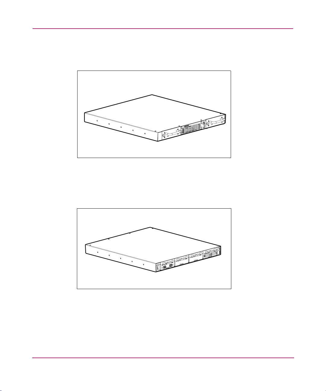
Figure 1 and Figure 2 show front and back views of the router.
Figure 1: Front view
The air intake vents on the front left side, shown in Figure 1, must remain
unobstructed. The power supply modules (with fault and power LED) are
serviceable from the front of the router. The serial port is also located on the front
for local management of configuration settings and firmware upgrades.
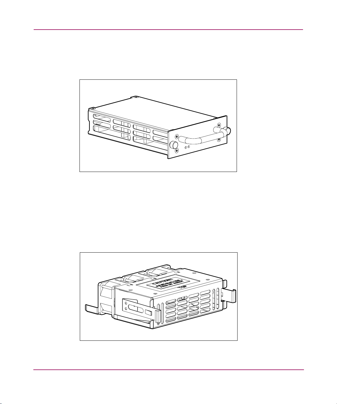
Figure 2: Back view
The air exhaust vents on the back left side, shown in Figure 2, must remain
unobstructed. The SCSI, Fibre Channel, and Ethernet ports are found at the back
of the router. Each port has LEDs that provide bus activity and link status
information. A single power connector and single po wer b utton are also located at
the back of the router.
24 Network Storage Router M2402 User Guide
Page 19
Power Module
The router is equipped with one power supply and has the capability of a
redundant power supply being added.
Figure 3: Power module
Power supply LED definition:
Introduction
Green - Power has been applied to this module
Fan Module
Yellow - Power-On Self-Test (POST) in process or processor problems
The router is equipped with three fans in a single module.
Figure 4: Fan module
25Network Storage Router M2402 User Guide
Page 20
Introduction
If one of the three fans fails, the router will continue to operate on the two
remaining fans until a replacement fan module can be installed.
If the fan is not cooling the router properly, a temperature warning message is
displayed in the Home Page of the Web-based user interface.
Fan module functionality can be verif ied from both the Serial/Telnet user interface
and the Web-based user interface.
Note: The Web-based user interface is also called Visual Manager. Visual Manager is
discussed in Chapter 4, The Serial/Telnet user interface is discussed in Chapter 5.
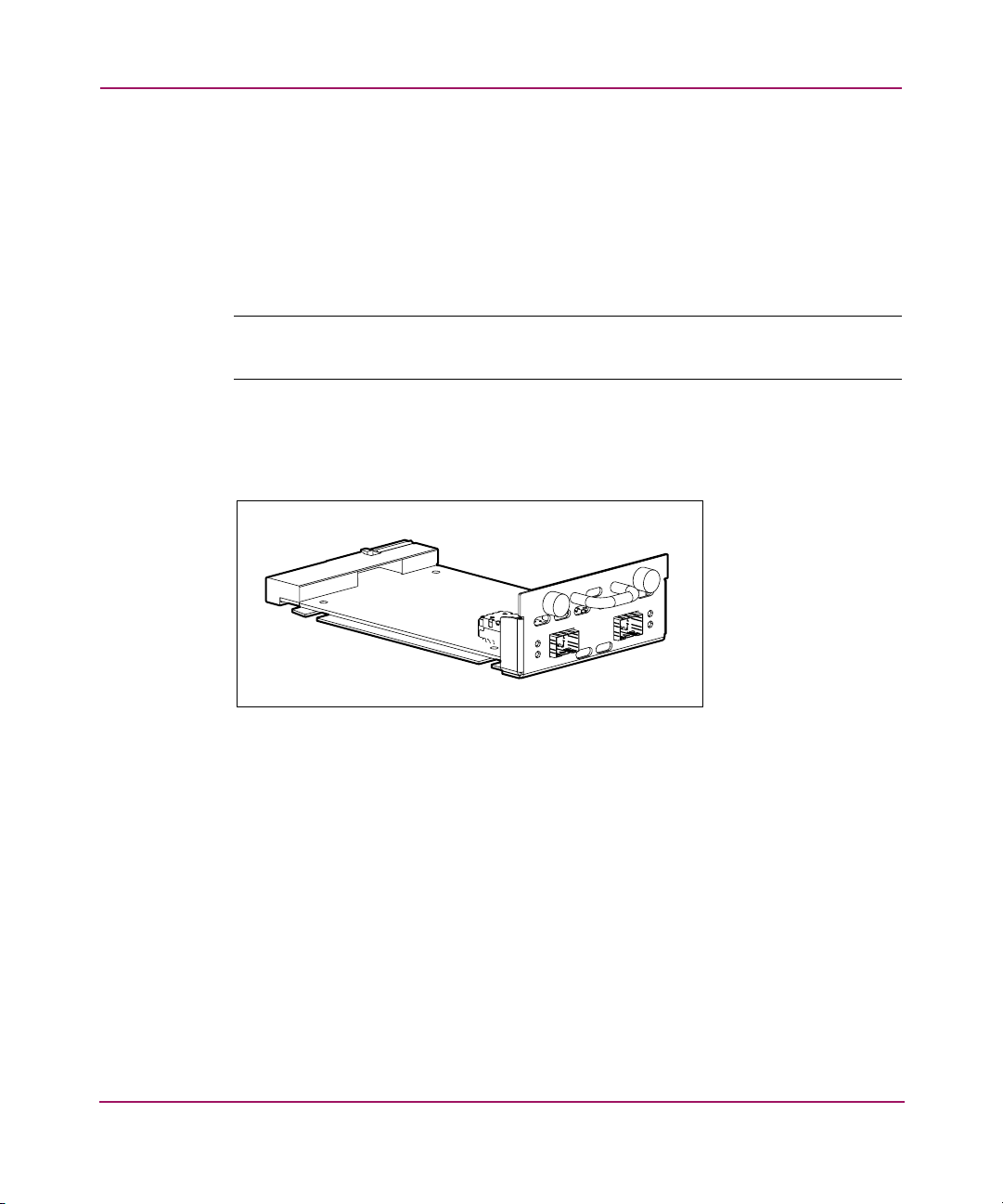
Fibre Channel Modules
Multiple Fibre Channel modules can be added to the router.
Figure 5: Fibre Channel module
Fibre Channel module LED definition:
Green (ACT) - Fibre Channel port activity
Green (LINK) - Valid Fibre Channel link
26 Network Storage Router M2402 User Guide
Page 21
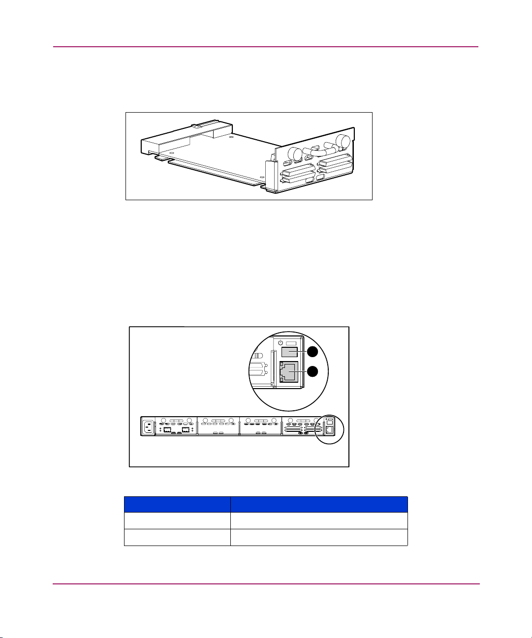
SCSI Modules
Multiple SCSI modules can be added to the router.
Figure 6: SCSI module
SCSI module LED definition:
Green - SCSI bus activity on corresponding port
Ethernet Port/Standby Power Button
The router is equipped with one Ethernet port and a standby power button with
LED indicators ( see Figure 7).
Introduction
2
1
Figure 7: Ethernet port/standby power button
Item Description
1 Ethernet port
2 Standby power button
27Network Storage Router M2402 User Guide
Page 22
Introduction
Serial Port
Ethernet port LED definition:
Activity - Port activity
Link - Valid Ethernet link
Standby power button LED definition:
Green - System power is on
Amber - System fault condition is indicated
Alternating Green/Amber - System in Beaconing mode
Note: The Standby Power button engages/disengages system power supplied from the
power modules. This button does not remove power to the power module(s). To remove
power to the power module(s), unplug the router from electrical source.
The standby power button has a 10-second delay after disengaging power before
power can be re-engaged.
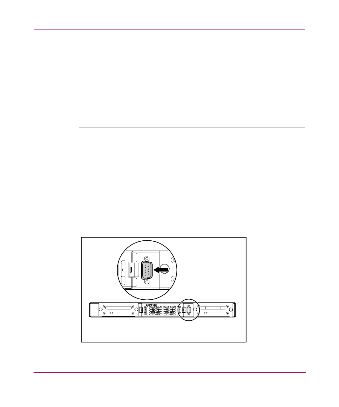
The router is equipped with one serial port (see Figure 8).
The serial port can be used to access the serial/Telnet user interface, which is used
to locally manage and configure the router.
Figure 8: Serial port
28 Network Storage Router M2402 User Guide
Page 23
Functional Overview
The router translates the Fibre Channel Protocol (FCP) to and from the SCSI
Protocol. It transfers commands, data, and status information to and from Fibre
Channel (FC) controllers and SCSI devices.
Supported devices include:
■ Initiator Devices – FC and SCSI hosts
■ Direct Access Devices – RAID Controllers, Disk drives, JBODs
■ Sequential Access Devices – Tape drives
■ Changer Devices – Tape and Magneto-Optical Libraries
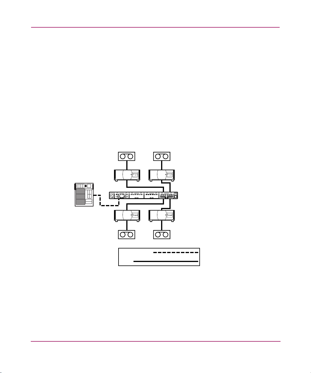
The router provides multiple FC to SCSI I/O configurations. A sample
configuration is illustrated in Figure 9.
SCSI
Tape
Drives
SCSI
Tape
Libraries
Introduction
StorageWorks
Router
FC Host
Fibre Channel
SCSI
Figure 9: Example configuration
SCSI
Tape
Libraries
SCSI
Tape
Drives
Figure 9 shows that a FC host on the FC bus can access a tape drive and library
through the appropriate SCSI bus of the router I/O module.
29Network Storage Router M2402 User Guide
Page 24
Introduction
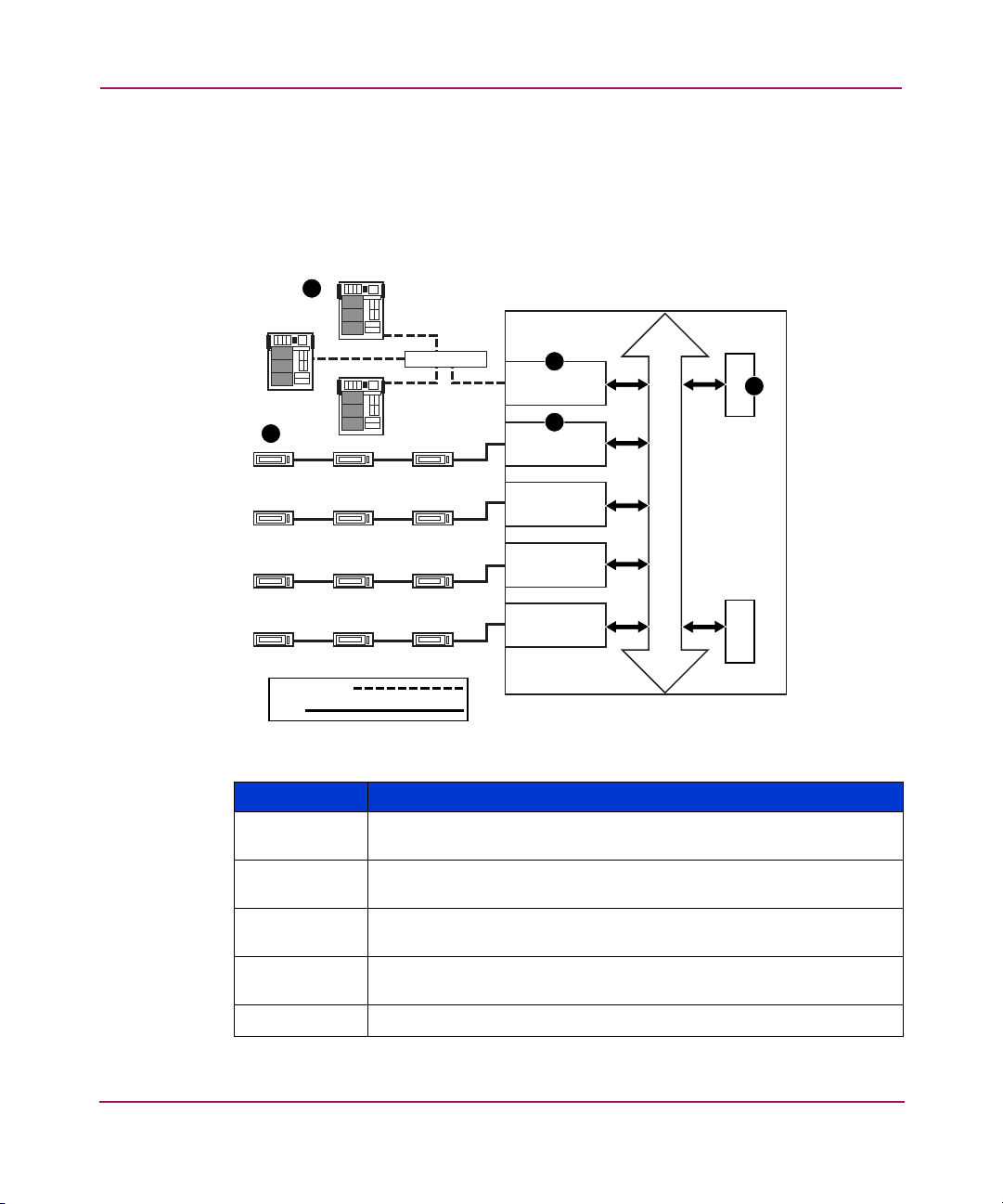
Fibre Channel to SCSI Protocol Process
This section describes the steps the router uses to convert FC host protocol to
SCSI device protocol. Figure 10 and the supporting table illustrate and define this
process.
FC Host
1
FC Host
StorageWorks Router
5
SCSI DeviceSCSI Device
Fibre Channel
SCSI
FC Host
Hub or Switch
SCSI Device
SCSI DeviceSCSI DeviceSCSI Device
SCSI DeviceSCSI DeviceSCSI Device
SCSI DeviceSCSI DeviceSCSI Device
2
FC Controller
4
SCSI Controller
SCSI Controller
SCSI Controller
SCSI Controller
Figure 10: Converting Fibre Channel to SCSI process
Item Process
1
A Fibre Channel host issues an encapsulated FCP protocol
command packet to the router
2
The router Fibre Channel controller interprets the Fibre Channel
information, and places the packet in buffer memory.
3
The router interprets the Fibre Channel information packet and
programs the router SCSI controller to process the transaction.
4
The router SCSI controller sends the command to the SCSI device
(target).
5
The SCSI target interprets the command and executes it.
3
Bus
Memory Processor
30 Network Storage Router M2402 User Guide
Page 25
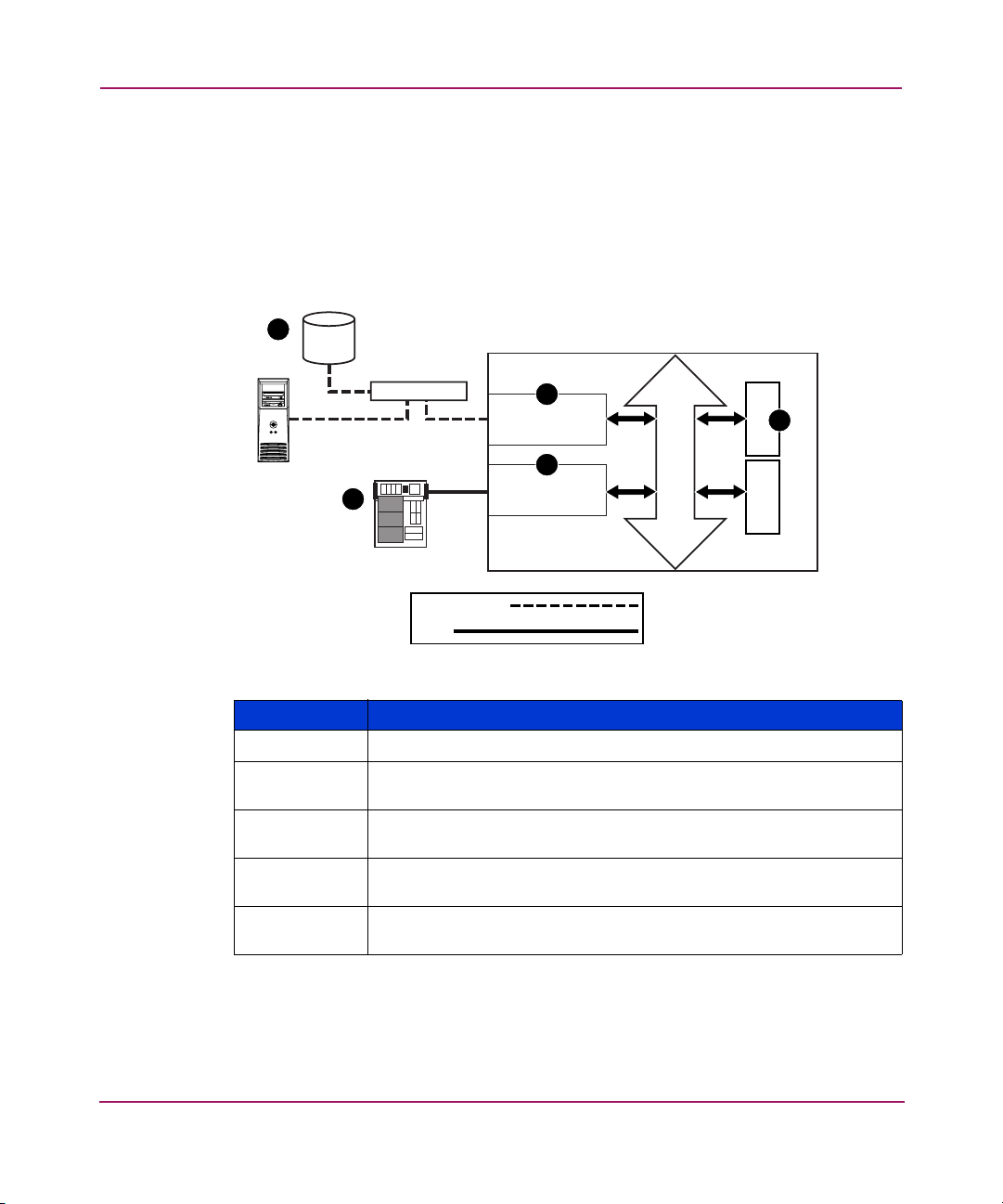
SCSI to Fibre Channel Protocol Process
In this example, a SCSI host (initiator) on the SCSI bus issues commands and the
information is passed through the router to a target on the Fibre Channel Storage
Area Network (FC-SAN). Figure 11 is an illustration of the process and the
supporting table defines each step.
FC Device
5
Introduction
StorageWorks Router
FC Device
Hub or Switch
SCSI Host
1
Fibre Channel
SCSI
4
FC Controller
2
SCSI Controller
Figure 11: Converting SCSI to Fibre Channel Protocol
Item Process
1
2
A SCSI host issues a command to the router.
The SCSI controller in the router interprets the command and
places it in buffer memory.
3
The router processor interprets data and programs the router
Fibre Channel controller to process the transaction.
4
The router Fibre Channel controller translates data into an FCP
protocol packet and sends it to the Fibre Channel target.
5
The Fibre Channel target interprets the FCP protocol packet and
executes the command.
3
Bus
Memory Processor
31Network Storage Router M2402 User Guide
Page 26
Introduction
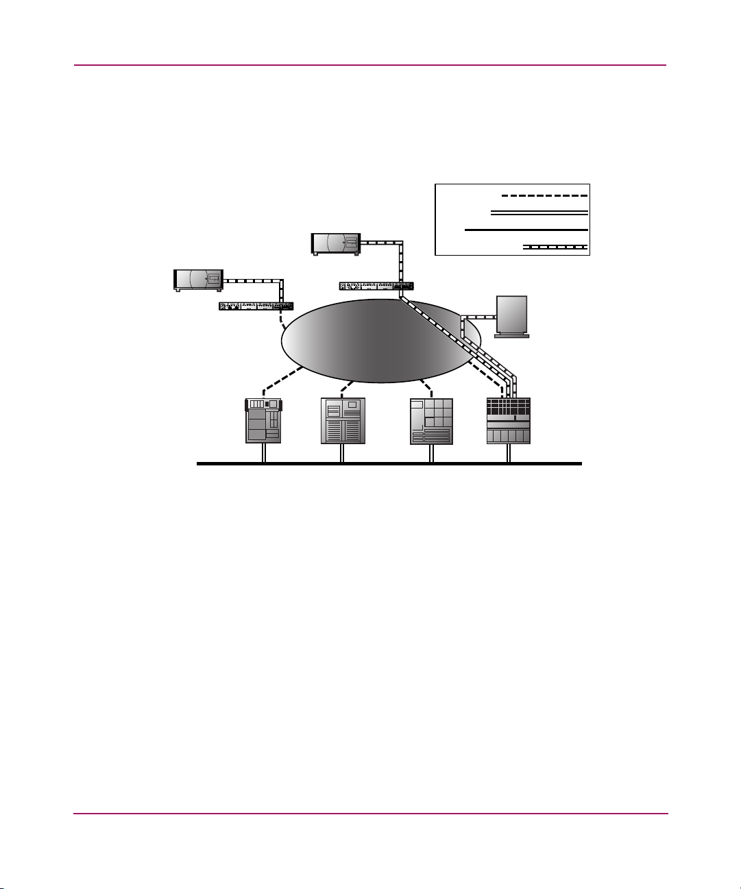
LAN-free Backup and Restore
The router can enable LAN-free backup/restore to allow the bulk of data traf fic to
be moved from the LAN to the storage area network (SAN) (see Figure 12).
SCSI TAPE
UNIT
StorageWorks
Router
SCSI TAPE
UNIT
StorageWorks
Router
SAN
Fibre Channel
ETHERNET
SCSI
DATA MOVEMENT
FIBRE CHANNEL
DISK
SERVER SERVER
SERVERSERVER
LAN
Figure 12: LAN-free backup and restore
32 Network Storage Router M2402 User Guide
Page 27
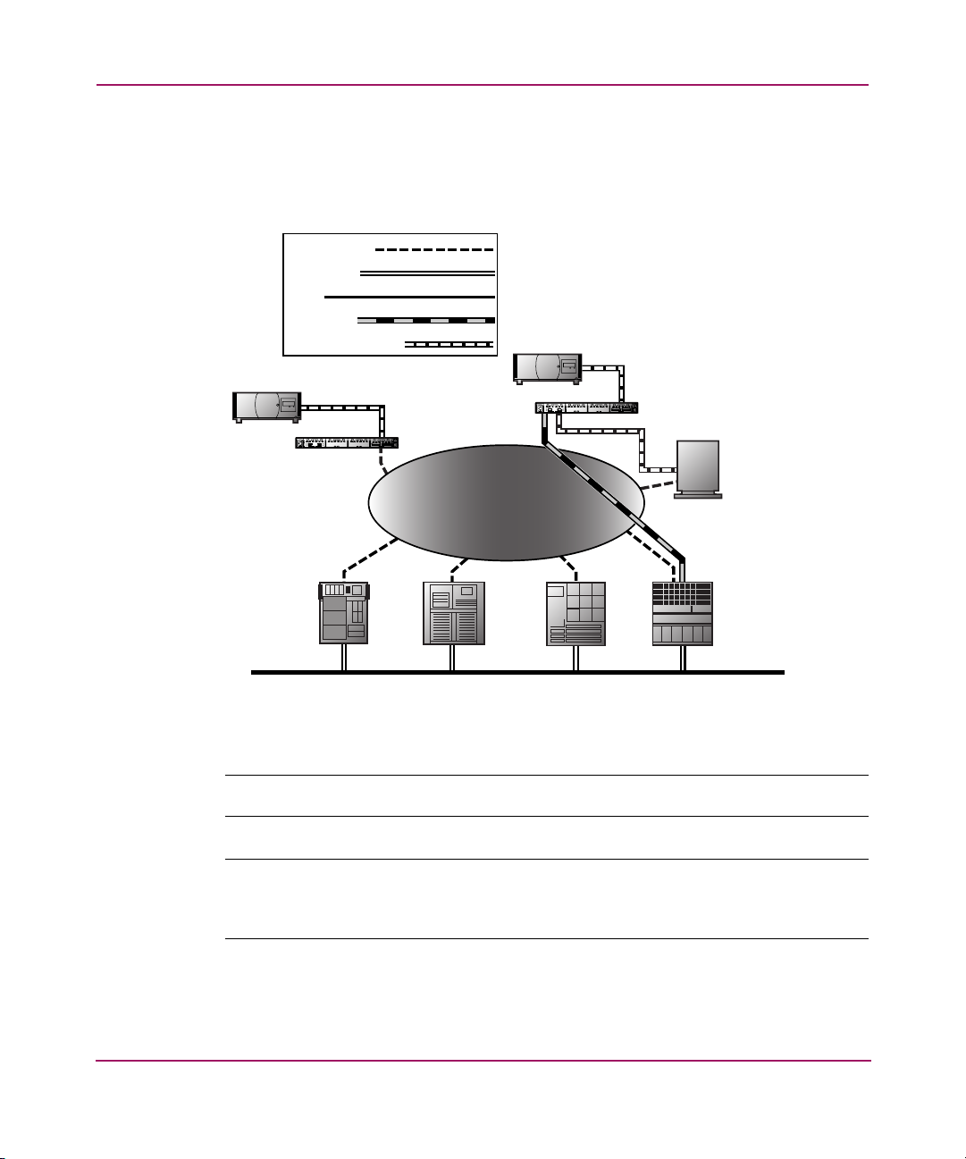
Server-free Data Movement
Used with server-free application software, Copy Manager allo ws the serv er to of f
load data movement to the router and free up server resources (see Figure 13).
Fibre Channel
ETHERNET
SCSI
COMMAND
DATA MOVEMENT
SCSI TAPE
UNIT
StorageWorks
Router
SCSI TAPE
UNIT
StorageWorks
Router
SAN
FIBRE CHANNEL
DISK
Introduction
SERVER SERVER
SERVERSERVER
LAN
Figure 13: Server-free data movement
Note: Copy Manager can perform simultaneous Extended Copy commands.
Note: Server-free backup can be activated using the Active Fabric Configuration
menu option. When activated, the router is enabled for both server-free and LAN-free
capabilities. When deactivated, only LAN-free capabilities are supported.
33Network Storage Router M2402 User Guide
Page 28

Introduction
Note: The router implementation of the Extended Copy command is available to
application programmers. See Appendix B, “Controller LUN Commands.”
Physical Requirements
The router has the following physical dimensions:
■ Width: 17.00 inches
■ Depth: 20 inches
■ Height: 1.70 inches, 1U
■ Weight: approximately. 18 lbs.
The router must be operated in the follo wi ng environment:
■ Temperature: 0 to 50°C
■ Relative Humidity: 5 to 80% (non-condensing)
If the router is to be shipped or stored, the following environment must be
maintained:
■ Temperature: -40 to +55°C
■ Relative Humidity: 0 to 92% (non-condensing)
The router must be supplied the following power:
■ VAC: 100 - 240 (auto sensing)
■ 50/60 Hz, 2.0 Amps (each power supply)
34 Network Storage Router M2402 User Guide
Page 29

Installation
This chapter describes how to unpack and install the HP StorageWorks Network
Storage Router M2402. The router can be set u p in ei ther a desktop or a rack
configuration.
Note: Read this chapter carefully and completely before configuring the router.
The following considerations and procedures are included in this chapter:
■ Selecting a Location, page 36
■ Unpacking the Box, page 36
■ Placing the Router on a Desktop, page 36
■ Installing the Router in a Rack, page 37
■ Connecting the Power Cord, page 42
■ Connecting the Interfaces, page 44
— Fibre Channel connections
2
— SCSI connections
— Ethernet connections
— Serial port connections
Caution: To prevent static shock, which can damage electrical equipment, use
industry accepted handling practices when unpacking and moving the router
and its components. See Appendix E, “Electrostatic Discharge,” for more
information.
35Network Storage Router M2402 User Guide
Page 30

Installation
Selecting a Location
The router can be placed on a desktop or installed in a standard 19-inch rack.
When considering a location for the router, make sure the airflow area
surrounding the front and the back of the router is unobstructed.
Unpacking the Box
Unpack the router as follows:
1. Remove all items from the shipping container. Check each one for damage.
Keep the router in the protective bag until ready to install.
2. Refer to the packing slip or contents list to make sure all the equipment was
received. If an item is missing, contact your sales representative immediately.
Placing the Router on a Desktop
1. Remove the router from the protective bag.
Caution: Place the router on a smooth surface away from any potential
exposure to direct sunlight, liquids or vapors, excessive heat, or risk of
accidental dropping or other damage.
2. Attach the stick-on feet to the bottom four corners of the unit.
3. Place the router on the table or desktop, ensuring the intake and exhaust vents
are clear of obstructions.
36 Network Storage Router M2402 User Guide
Page 31

Installing the Router in a Rack
The following items in the router kit are used to rack-mount the router:
■ Mounting rails
■ Extender brackets
■ Bag of mounting hardware (8 #M6x12 Phillips screws, 4 #6-32x.312 Phillips
screws)
■ Bezel blank
Note: The installation process requires a #2 Phillips and a #2 flat-head screwdriver.
To install the router in the rack:
1. Remove the router from its protective bag.
Note: Before installing the router, make sure that all modules are properly installed.
For information about the removal or installation of modules, refer to Chapter 7,
“Hardware Module Replacement.”
Installation
Caution: Place the router onto a smooth surface away from any potential
exposure to direct sunlight, liquids or vapors, excessive heat, or risk of
accidental dropping or other damage.
2. Determine where the router will be installed, ensuring that the air-flow vents
remain clear of obstructions.
3. Separate the inner rail from the outer-rail assemblies (see Figure 14).
a. Place a thumb or finger over the circular grasping hole at the front-end of
the inner rail.
b. Extend the inner rail out from the outer-rail assembly until it locks into
place.
c. Press the spring-latch on the back of the inner rail to release the lock.
While holding down the spring-latch, extend the inner rail until the two
rails separate.
37Network Storage Router M2402 User Guide
Page 32

Installation
View From
Opposite Side
3
2
Spring Latch
Front of Inner
Rail
Circular Grasping Hole
1
Front of Outer
Rail
Extension
Bracket
Figure 14: Separating the inner and outer rails
d. Repeat Step 3 to separate the other set of rails.
4. Attach the front-end and back-end of each outer-rail assembly to the rack.
a. Determine the location in the rack for the router.
Note: The size of the router and its rail assembly is 1U.
b. Align the three screw-holes on the front-end of the outer-rail assembly
with the equally spaced holes on the front of the rack. All three holes must
be aligned exactly. If the holes do not exactly match up, the outer-rail
assembly is not positioned correctly on the rack (see Figure 15).
Figure 15: Aligning the bracket face with the rack
38 Network Storage Router M2402 User Guide
Page 33

c. With the outer-rail assembly face flush against the inside front of the
rack-mounting holes, using two M6x12 Phillips screws, insert and tighten
the top and bottom screws of the bracket face.
Do not insert a screw in the center hole of the bracket face. This hol e wil l
be used when the front bezel blank is mounted to the rack.
d. Loosen the flathead screw on the rear extension bracket of the outer-rail
assembly.
e. While holding the outer-rail assembly level, extend the rear extension
bracket to the inside back of the rack.
WARNING: To reduce injury or equipment damage, the rails must be level.
If the rails are not level, the router cannot be installed correctly and could
fall.
f. Attach the rear extension-bracket face to the back of the rack, using two
M6x12 Phillips screws.
g. With the outer-rail assembly in place, tighten the flathead screw that
connects the rear extension bracket to the outer rail.
h. Repeat Step 4 to attach the other outer-rail assembly to the other side of
the rack.
5. Attach an inner rail to each side of the router (see Figure 16).
Installation
a. With the spring-latch facing away from the router and the circular
grasping hole facing the front-side of the router, align the front-most
screw-hole on the router with the center screw-hole on the rail.
Using this alignment, two screw holes will be aligned and the rail will
extend out from the front-side of the router approximately 8 inches.
b. Secure the rail to the router using two #6-32x.312 Phillips screws.
39Network Storage Router M2402 User Guide
Page 34
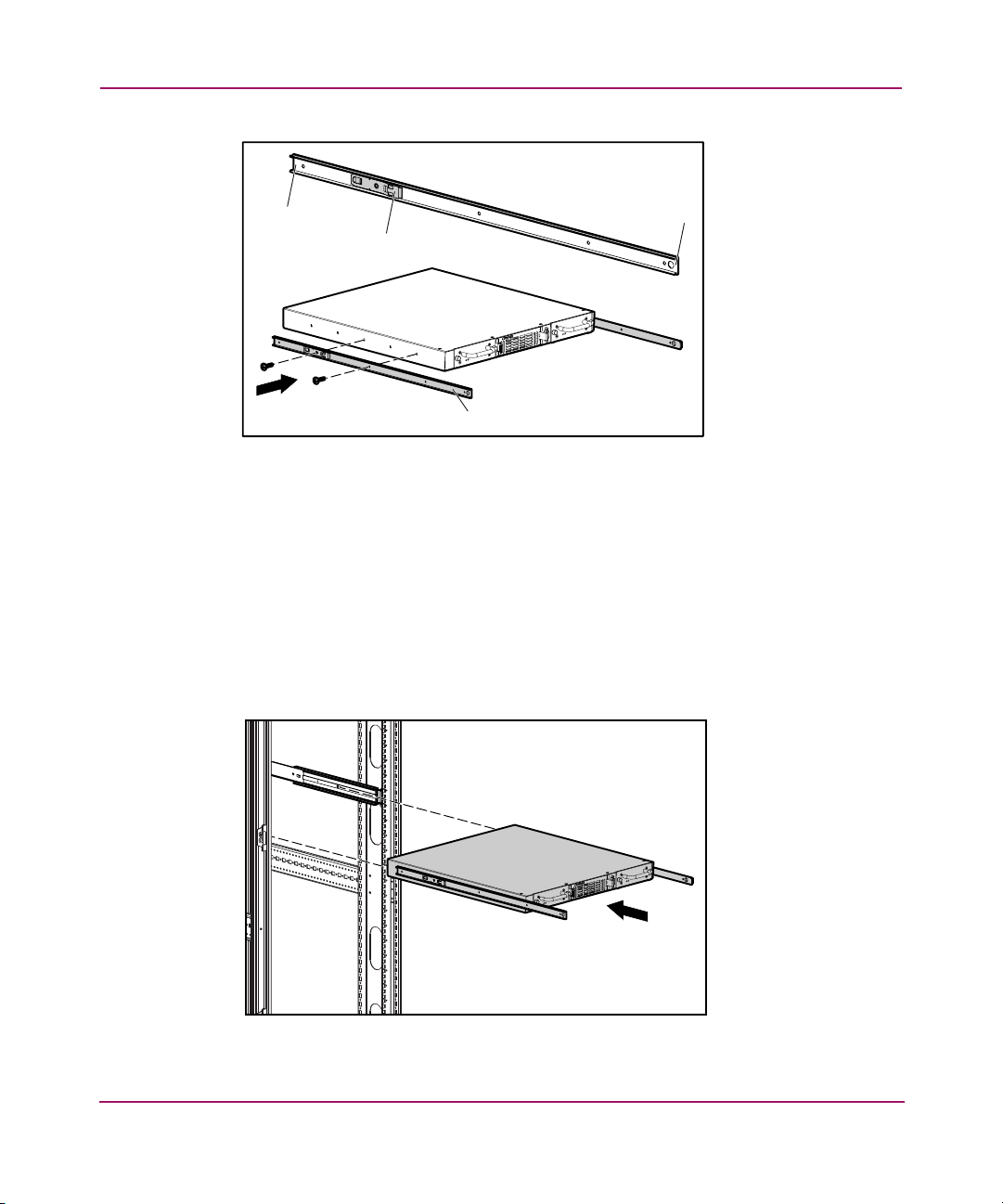
Installation
Back End
Spring Latch
Inner Rail
Front End
Figure 16: Attaching inner rails to the router
c. Repeat Step 5 to attach the inner rail to the other side of the router.
6. Install the router in the rack (see Figure 17).
a. Move the ball-bearing slide on each of the outer rails towards the front of
the rack.
b. From the front-side of the rack with the front-side of the router facing out,
align the inner and the outer rails and slide the inner rail into the outer rail.
c. When the rails lock in place, press in the spring-latches on each of the
inner-rails and push in the rest of the way.
Figure 17: Installing the router into the rack
40 Network Storage Router M2402 User Guide
Page 35

7. Attach the bezel blank to the front-side of the rack (see Figure 18).
a. Align the bezel blank over the unused center hole of the bracket faces on
the rack.
b. Attach the bezel blank to the rack, using the thumbscrews.
Figure 18: Attaching the bezel to the rack
Installation
41Network Storage Router M2402 User Guide
Page 36

Installation
Connecting the Power Cord
WARNING: This product can ONLY be used with an HP approved power
cord for your specific geographic region. Use of a non-HP approved power
cord may result in:
■ Not meeting individual country specific safety requirements;
■ Insufficient conductor ampacity that could result in overheating with
potential personal injury and/or property damage; and
■ An unapproved power cord could fracture resulting in the internal
contacts being exposed, which potentially could subject the user to a
shock hazard.
HP disclaims all liability in the event a non-HP approved power cord is used.
The internal power supply will support 100 - 240 VAC (Auto Sensing). The
power cord shipped with the router is a 120 VAC three-conductor power cord for
use in the United States and Canada. If the router is being installed outside the
United States or Canada, the appropriate power cord must be purchased .
WARNING: To reduce the risk of electric shock or damage to the
equipment:
■ Do not disable the power-cord grounding-plug. The grounding plug is an
important safety feature.
■ Plug the power cord into a grounded (earthed) electrical outlet that is
easily accessible at all times.
■ Disconnect power from the router by unplugging the power cord from
either the electrical outlet or the router.
42 Network Storage Router M2402 User Guide
Page 37

Installation
To connect the power cord to the router (see Figure 19):
1. Connect the power cord to the power connector on the back of the router.
2. Connect the power cord to a grounded voltage source.
Figure 19: Power connector
43Network Storage Router M2402 User Guide
Page 38

Installation
Connecting the Interfaces
There are four types of interfaces on the router:
■ Fibre Channel Connections
■ SCSI Connections (HVD or LVD/SE)
■ Ethernet Connections
■ Serial Port Connections (RS-232)
Figure 20 is an illustration of the port locations on the router.
1 2
3
4
Figure 20: Front and back port locations
Item Port Type
1
2
3
4
44 Network Storage Router M2402 User Guide
Fibre Channel
SCSI
Ethernet
Serial
Page 39

For convenience in configuring ports, important information can be found on a
label located on the underside of the router (see Figure 21).
WWNN: 100000E00200N000
WWPN: 100000E00Y00N000
ENET MAC ID: 00:E0:02:00:00:XY
Figure 21: WWN/MAC ID label
Fibre Channel Connections
In typical installations, the router may be connected to:
■ Arbitrated Loop (AL) – the router can be directly attached to the FC host
adapter in a point-to-point configuration.
■ Private loop (hub)
■ Public loop (hub that is also connected to a switch)
■ Fabric environment (switch)
Installation
Note: Before connecting the router to other Fibre Channel devices, it is important to
understand the configuration requirements of the environment to which it will be
connected. Failure to correctly configure a Fibre Channel device may impair the
operation of the storage network to which it is attached.
45Network Storage Router M2402 User Guide
Page 40

Installation
Fibre Channel Hub
Max 10 Km
Distance
Host
Max 10 Km
Distance
StorageWorks
FC HBA
SCSI
Tape Library Tape Library
Fibre Channel
SCSI
Router
Tape Library Tape Library
Figure 22: Configuration with tape library using Arbitrated (or Private) loop
Both FC switches and hubs may allow individual ports to be configured for
different media types. The router must be connected to the hub or switch port with
the appropriate FC cabling for the media type in use.
The router supports various FC media types, using external Small Form Factor
Pluggables (SFP).
Available media types use 2.125-Gb Dual SC connectors and include:
■ Multi-mode fiber support
■ Single-mode fiber support
46 Network Storage Router M2402 User Guide
Page 41

Installation
To connect the router to a FC storage area network (SAN):
1. Locate the FC ports on the back of the router (see Figure 23).
Figure 23: Fibre Channel ports
2. Remove the rubber protective inserts from the Small Form Factor Pluggables
(SFP).
3. With the router powered off, connect the router to the FC environment, using
the appropriate cabling. The FC optical connectors on the router are ke yed for
proper orientation.
Caution: The router has been qualified with a specific set of SFPs. Using an
SFP that has not been qualified by HP may cause the router to operate
improperly. See the Laser Safety section of this manual for more information.
47Network Storage Router M2402 User Guide
Page 42

Installation
SCSI Connections
The router supports Fast/Ultra-2 Narrow/Wide SCSI. The router is factory
configured to support LVD/Single-Ended or HVD (Diff), or a mixture of both
types of SCSI buses. Up to twelve SCSI buses can be attached, using 3 SCSI
modules.
Note: The router must always be installed at the end of SCSI buses.
The router supplies termination power (TERMPWR) to each SCSI bus.
Note: During certain faults, the termination power IC will shut down. It may be
restarted once the fault is cleared.
Caution: During the attachment of high density SCSI cables, note the
orientation of the high-density SCSI port connectors. Connector orientation
failure may result in connector damage.
Caution: LVD/SE and HVD connections must be made on appropriate I/O
modules. Failure to heed this caution may result in damage to equipment.
Caution: Failure to comply with the minimum high-density cable
specifications can result in damage to the router or an operational failure of
the product.
48 Network Storage Router M2402 User Guide
Page 43

Installation
Note: SCSI cables used with the router must meet SCSI 2 standards. Optional SCSI
cables are available from your supplier.
To connect the router to a SCSI device:
1. Power off the router and SCSI devices.
2. Locate the SCSI buses on the back of the router (see Figure 24).
Figure 24: SCSI buses
3. Connect a SCSI cable to one of the SCSI buses on the router.
Note: The router should always be installed at the end of the SCSI bus.
Note: SE is not supported by SCSI-3 protocols. While it is possible to mix SE and LVD
devices on the same bus, doing so will result in substantially decreased performance
on the bus.
4. Connect the SCSI cable to the SCSI device.
5. Verify that the bus is terminated correctly. By default, the router is
automatically terminated. However, the device at the other end of bus must
also be terminated.
49Network Storage Router M2402 User Guide
Page 44

Installation
6. Power on all attached SCSI devices.
7. After all the SCSI devices have completed their individual POST (Power-On
Self-Test) processes, power on the router.
Ethernet Connections
10/100BaseT Ethernet connectivity provides enhanced management and
configuration capabilities. The RJ-45 connector on the router can be directly
connected to a standard 10/100BaseT Ethernet network.
To allow configuration capabilities via this port, the IP network address must be
set. The IP network address can be manually assigned or dynamically assigned
using DHCP. Refer to Chapter 4 or Chapter 5 for details on setting the IP network
address.
Note: The router has a unique Ethernet MAC address that is assigned during the
manufacturing process.
Ethernet interfaces include Telnet, FTP, and an HTTP interface known as HP
StorageWorks Visual Manager (VM). For more information on router
management, see Chapter 3, “Configuration Overview .”
Figure 25: Ethernet port
50 Network Storage Router M2402 User Guide
Page 45

Serial Port Connections
The DB-9 connector provides a serial port that is compliant with the EIA 562
standard and is RS-232 signaling-level compatible. The serial connection can be
used to configure the unit, to monitor its diagnostic status, or to update the router
firmware. Figure 26 is an illustration of the serial port location on the front of the
router.
Installation
Figure 26: Serial port
Item Settings
Baud Rate Autobaud, 9600, 19200, 38400, 57600, or 115200
HP recommends setting the baud rate to 115200.
Data Bits 8
Stop Bits 1
Parity None
Flow Control None or XON/XOF
51Network Storage Router M2402 User Guide
Page 46

Installation
Setting up Serial Port Communications
To set up serial port communications:
1. Connect the serial cable between the host computer serial port (COM1 or
COM2) and the router serial port.
2. Power on the router.
3. Power on the server.
4. Start the host terminal or terminal interface program (Microsoft Windows 9x,
Windows NT 4.0, or Windows 2000 HyperTerminal).
5. Set the terminal or terminal interface program to use the appropriate COM
port.
6. Configure the selected COM port.
7. Press Enter several times. The router will automatically detect the baud rate
being used. The baud rate will be retained through future power cycles.
Note: This process can take up to 90 seconds. The Power On Self Test (POST) and
initialization information may not be visible on screen.
Note: The baud rate in the terminal emulation program must be set at 9600,
19200, 38400, 57600, or 115200 to use the autobaud feature.
52 Network Storage Router M2402 User Guide
Page 47

Configuration Overview
The HP StorageWorks Network Storage Router M2402 can be configured and
managed using several user interfaces (UI). E ach UI is introduced in this chapter,
along with information about common configuration settings.
■ Router Default Settings, page 54
■ UI Overview, page 55
■ Common Configuration Settings, page 56
— Controller LUN commands
— SCSI bus configuration
— Fibre Channel port configuration
— Fibre Channel arbitrated loop configuration
— Fibre Channel switched fabric configuration
—Discovery mode
— Host device configuration
— Logical unit management
— Buffered tape writes
3
Note: Before attempting to configure the router, a basic understanding of Fibre
Channel and SCSI devices is recommended. For information on SCSI standards,
refer to publications from the X3T10 committee of ANSI (American National
Standards Institute). For information on Fibre Channel standards, refer to
publications from the X3T11 committee of ANSI. For those who are interested in
purchasing approved American National Standards and Technical Reports, you can
contact ANSI at (212) 642-4900.
53Network Storage Router M2402 User Guide
Page 48

Configuration Overview
Router Default Settings
Some of the basic factory default values are:
■ IP address: http://1.1.1.1/
■ Subnet mask: 255.255.255.0
■ Gateway address: 0.0.0.0
■ User name: root
■ Password: password
HP recommends these values be changed from the defaults.
All settings within the router configuration are pre-set with default values. These
values are set to allow the router to be installed into most HP environments with
little or no configuration changes.
After changing the basic default values listed above, carefully consider any
additional configuration changes.
After the initial configuration of the router is established, HP recommends
backing up the configuration to an external file. If needed, during a recovery
process, this file can then be restored back onto the router.
54 Network Storage Router M2402 User Guide
Page 49

UI Overview
The router supports the following user interfaces:
■ Visual Manager
■ Serial/Telnet
■ FTP
Each UI is introduced in the following paragraphs.
Visual Manager
Visual Manager allows any standard web browser to view and change router
configuration. Information is dynamically generated in an HTML format so that
any web browser can access it.
Unless the default values are used, the 10/100BaseT Ethernet port must be
configured using the serial port with an appropriate IP address, subnet mask, and
gateway prior to use.
For complete information on accessing and using Visual Manager, see Chapter 4,
“Visual Manager User Interface.”
Configuration Overview
Serial/Telnet
FTP
The serial port allows for configuration of device characteristics from a terminal
or terminal emulator. Multiple serial connections cannot be run at the same time.
From most Windows 9x, Windows NT, and Windows 2000 systems, users can
start a Telnet session from the DOS (Command) shell.
For complete information on accessing and using the Serial/Telnet UI, see
Chapter 5, “Serial/Telnet User Interface.”
The router supports the use of the FTP UI to perform several copy procedures
using the “
For more information, see Chapter 6, “FTP User Interface.”
put” and the “get” commands.
55Network Storage Router M2402 User Guide
Page 50

Configuration Overview
Common Configuration Settings
To provide connectivity between hosts and devices, the router must establish an
address on each connected FC network and SCSI bus. The following paragraphs
discuss configuration settings that are commonly modified and are av ailable in the
Visual Manager UI and the Serial/Telnet UI. For procedural information on
accessing and changing these settings, see Chapter 4, “Visual Manager User
Interface,” and Chapter 5, “Serial/Telnet User Interface.”
Controller LUN Commands
The router supports a set of SCSI-3 commands that can be received as FCP
commands over the FC bus. These commands provide support for value added
features such as Extended Copy. When using these commands, they must be sent
to the Controller LUN. For more information, see Appendix B, “Controller LUN
Commands.”
SCSI Bus Configuration
The router can appear on a SCSI bus as a pair of initiators. The primary Initiator
ID can be set to any valid SCSI address (0-15) and is used for most traffic. The
alternate Initiator ID can also be set to any valid SCSI address (0-15) and is for
use with high priority traffic. The Initiator IDs (primary and alternate) should not
be set to the same SCSI address and no other devices on the SCSI bus may use
either of these SCSI addresses.
The router can also appear as one or more Target ID on a SCSI b us. By defau lt, no
Target IDs are set up.
The router provides the capability to reset SCSI buses during the router boot
cycle. This allows devices on a SCSI bus to be in a known state. The reset option
can be enabled/disabled during configuration of the router. The SCSI bus reset
feature is enabled in the default configuration but should be disabled for
configurations using multiple initiators, tape changers or other devices that have
long reset cycles, or for environments that are adversely affected by bus resets.
The router negotiates the maximum values for transfer rates and bandwidth on a
SCSI bus. If an attached SCSI device does not allow the full rates, the router will
use the best rates it can negotiate for that device. Because negotiation is on a
device-specific basis, the router can support a mix of SCSI device types on the
same SCSI bus.
56 Network Storage Router M2402 User Guide
Page 51

Fibre Channel Port Configuration
By default, the configuration of the FC ports is set to N_Port, which minimizes
conflicts when both the router and another FC device, such as a switch, are using
Auto Sensing for FC ports. Alternatively, the configuration of the FC ports can be
set to Auto Sensing, which allows the router to detect whether it is connected to an
Arbitrated Loop or a Switched Fabric.
Note: By default, the Fibre Channel port speed is set to 1 Gb/s. Changes to the Fibre
Channel port speed must be manually set, such as for 2 Gb/s. If set incorrectly and the
router is plugged into a Loop or Fabric, the unit may receive framing errors because of
the incorrect Fibre Channel link speed.
Fibre Channel Arbitrated Loop Configuration
On a Fibre Channel Arbitrated Loop, each device appears as an Arbitrated Loop
Physical Address (AL_PA). To obtain an AL_PA, two methods can be used:
■ Soft addressing
■ Hard addressing
Configuration Overview
Soft addressing is the default setting.
Soft Addressing
During soft addressing, the router automatically acquires the first available loop
address, starting from 01 and moving up to EF. The router may participate on the
FC loop, as long as there is at least one address avail able o n the loop connected to
the router. FC supports up to 126 devices on an Arbitrated Loop.
Hard Addressing
During hard addressing, the router attempts to acquire the AL_PA value specified
in the configuration settings. If the desired address is not available at loop
initialization time, the router negotiates the next available soft address. This
allows both the loop and the router to continue to operate.
57Network Storage Router M2402 User Guide
Page 52

Configuration Overview
Hard addressing is recommended for FC Arbitrated Loop environments where it
is important that the FC device addresses do not change. Device address changes
can affect the mapping represented by the host operating system to the
application, and have adverse effects. An example is tape library installation,
where the application configuration requires fixe d de v ice identif ication for prop er
operation.
Fibre Channel Switched Fabric Configuration
When connected to a FC switch, the router is identified to the switch as a unique
device by the factory programmed World Wide Name (WWN).
Discovery Mode
This feature makes it easy to discover attached FC and SCSI target devices and
automatically map them on the host side for the bus/port in question.
There are two discovery methods available:
■ Manual discovery
■ Auto discovery
Auto Discovery can be set to occur after reboot events (when the router reboots)
or link-up events (for instance, when cables are attached or a hub is rebooted).
Auto Discovery can be disabled by setting the router to Manual Discovery.
Host Device Configuration
A host system using a FC Host Bus Adapter (HBA) will typically map devices
into the existing device-mapping scheme used by that operating system. Refer to
the HBA manual for the mapping table.
Mapping involves pairing FC_AL_PA to SCSI target address. The HBA will
claim enough SCSI bus entries to allow up to 125 FC targets to be mapped to
SCSI Bus:Target entries. This is usually done by a fixed mapping of AL_PA to
Bus:Target. In such a configuration, the router corresponds to a Bus:Target
identifier, with the attached SCSI devices appearing as logical units (LUNs).
Operating systems can extend the available SCSI limit of 15 targets per bus.
Although this is not an issue for the operating system or most applications, there
are cases where older applications can have expectations about what constitutes a
valid SCSI ID, and thus may not correctly handle certain mappings. In particular,
some applications may exhibit difficulties addressing target IDs greater than 15
58 Network Storage Router M2402 User Guide
Page 53

(16 and up, for example). This situation can be resolved by configuring the router
to use hard addressing and setting the AL_PA to a value less then 16 that the HB A
will be able to map.
For example, depending on the FC HBA, if the hard AL_PA selection is 1, then
the address is 1. If the selection is 125, the AL_PA address is 0xEF. Some FC
HBAs will map devices differently, so verify the AL_PA by reviewing the
documentation for the HBA.
Logical Unit Management
Because SAN resources can be shared, it is possible for multiple hosts to have
access to the same devices on the SAN. To prevent conflicts, the router provides
LUN management as a means to restrict device access to certain hosts. LUN
management goes beyond simple LUN masking, to prevent gaps in the list of
LUNs presented to a host.
LUN management maps can be created for different views of the devices attached
to the router. E ach FC host is assigned a specific map conf iguration. Not only can
the administrator control which devices a host may access, but also which LUNs
are used to access these devices.
For a FC host, a map is a table of LUNs, where each entry is either empty or
contains device address information needed for host/device comm un ic ation.
For a SCSI host, a map contains a list of target IDs, each of which has its own
table of LUNs with address information needed for host/device communication.
Configuration Overview
Note: The router can respond to multiple Target IDs on a SCSI bus.
Both FC ports and SCSI buses have user-defined maps and pre-defined maps.
There are three predefined maps:
■ Indexed (default)
■ Auto Assigned
■ SCC
When a host sends a command, the router will select which map to use, based on
the port receiving the command and the ID of the host sending the comman d. For
FC ports, the host ID is the World Wide Name and for SCSI buses, the host ID is
the Initiator ID (0 - 15). When a host is unknown or is not assigned a specif ic map,
the router will use the default map.
59Network Storage Router M2402 User Guide
Page 54

Configuration Overview
Indexed Maps
An Indexed map is initially empty and can be modified by the user.
Auto Assigned Maps
An Auto Assigned map is built dynamically and contains all of the devices found
during discovery. This map will change automatically any time the discovery
process finds a change in the devices attached. This map cannot be modified by
the user.
SCC Maps
An SCC map is only available on FC ports and contains only a single entry for
LUN 0. This LUN is a router controller LUN. Access to attached devices is
managed using SCC logical unit addressing.
Buffered Tape Writes
This option is designed to enhance system performance by returning status on
consecutive write commands prior to the tape device receiving data. In the event
that data does not transfer correctly, the router will return a check condition on a
subsequent command.
Commands other than Write are not issued until status is received for any pending
write, and status is not returned until the device completes the command. This
sequence is appropriate for tasks such as file backup or restore.
Some applications require confirmation of individual blocks being written to the
medium, such as for audit trail tapes or log tapes. In these instances, the Buffered
Tape Writes option must be disabled.
60 Network Storage Router M2402 User Guide
Page 55

Visual Manager User Interface
The HP StorageWorks Visual Manager user interface (UI) provides a graphical
and intuitive format that is used to remotely view and change router
configurations. Use the Microsoft Internet Explorer or Netscape (version 6.2 or
greater) Web browsers to access Visual Manager.
Information is presented in HTML format in accordance with the W3C
specification for HTML 3.2. Current W3C recommendations and other technical
documents can be found at http://
This chapter describes the menus and tasks of the Visual Manager UI and is
organized using the same structure of the Visual Manager UI:
■ Visual Manager Access, page 63
■ Visual Manager Best Practices, page 65
■ Main Menu, page 66
■ System Menu, page 69
— Serial configuration
— Network configuration
— SNMP configuration (not supported)
4
www.w3.org/TR/.
— Active Fabric configuration
— User Configuration
— Real-Time clock configuration
— Power Supply configuration
— Reset Menu
■ Modules Menu, page 80
— World Wide Node Name configuration
— Fibre Channel Module configuration
— SCSI Module configuration
61Network Storage Router M2402 User Guide
Page 56

Visual Manager User Interface
■ Discovery Menu, page 92
■ Mapping Menu, page 93
— Fibre Channel and SCSI common mapping tasks
— Fibre Channel mapping tasks
— SCSI mapping tasks
■ Statistics Menu, page 103
■ Utilities Menu, page 104
— Beacon mode configuration
— FTP utility access
— Trace settings configuration
— Current, previous, and last assert trace displays
— Clear current traces and clear assert traces
— Event log configuration
— Event log display
■ Trace Settings Configuration, page 108
■ Report Menu, page 115
■ Reboot Option, page 116
62 Network Storage Router M2402 User Guide
Page 57

Visual Manager Access
Visual Manager (VM) can be accessed from any standard web browser:
1. Connect a 10/100BaseT Ethernet cable to the back of the router.
2. Apply power to the connected SCSI and/or FC devices.
3. After all of the devices have completed their power up routines, apply power
to the router.
4. Apply power to the host computer.
5. Enter the router IP address in the address field of the Web browser of the host
computer.
Note: To access VM, the router must be assigned a valid IP address. The factory
default setting for the IP address allows access on a local area network only. If the
factory default for the IP address is already used by another device on the local
network, the IP address must be changed.
The factory default for the IP address is http://1.1.1.1/
Visual Manager User Interface
Note: If the IP address of the router is not known or needs to be changed, connect to
the router using a serial connection. The current router IP address is displayed and can
be changed in the serial Ethernet Configuration Menu.
6. Router status information is displayed in the Visual Manager home page. The
home page is accessible to anyone who knows the router IP address.
To access any other menus and screens, the user must enter the autho r ize d
user name and password. The default user name is
password is
Note: User name and password are case-sensitive. HP recommends changing the user
name and password from the defaults
password. This information is required only once per session.
root and the default
63Network Storage Router M2402 User Guide
Page 58

Visual Manager User Interface
7. After entering the user name and password, full access is gained to the VM
menus.
Note: To end the current session of VM, it is necessary to close the browser window.
Navigating the browser to another URL does not end the current session.
64 Network Storage Router M2402 User Guide
Page 59

Visual Manager Best Practices
The following recommendations should be observed:
■ A standard keyboard and mouse must be used to navigate in the VM.
■ The router is shipped with a configuration of default settings that is acceptable
for most system environments. Few changes to the configuration should be
necessary.
■ After any configuration changes are made, depending on the menu option,
select Submit or Configure to send changes from the Web browser to the
router.
■ Changes will take effect during the next router reboot cycle.
■ If the configuration has been modified to meet company-specific needs, back
up the company-specific configuration to an external file. If necessary, these
settings can later be restored to the router.
■ Fields are not case-sensitive, except for the user name and password.
■ HP recommends that you not bookmark VM pages with the Web browser.
■ Because configuration information is transmitted via URLs, it is possible that
the router could be configured with information present at the time a page was
bookmarked.
■ HP recommends navigating only using the Web page links contained in VM
itself.
Visual Manager User Interface
■ Depending on the Web browser used, these links will often appear as
highlighted text. By selecting these links, VM can be safely navigated.
65Network Storage Router M2402 User Guide
Page 60

Visual Manager User Interface
Main Menu
The Main Menu home page is displayed whenever VM is accessed.
The home page contains status information, including a physical image of the
back of the router.
Figure 27 is an example of the home page.
Figure 27: Visual Manager home page
66 Network Storage Router M2402 User Guide
Page 61

Visual Manager User Interface
Home page information includes:
■ The HP logo is located in the upper left corner of the page. Figure 28 is an
example of this portion of the home page screen. If the Internet is accessible
to the host, click the HP logo to open the router company website.
Figure 28: HP logo
■ A back view of the router is located near the top of the home page
(see Figure 29).
Figure 29: Back view of the router
■ The router image is interactive, allowing quick access to conf iguration menus:
— To display current settings and status for a module, click the
corresponding module shown in the router image.
— To open a menu for making changes to the configuration for that
particular port or bus, click the desired FC port or SCSI bus.
— T o open the Po wer Supply Conf iguration menu, click the po wer connector
image.
— To open the Network Configuration menu, click the Ethernet port.
— To open the Beacon settings menu, click the System Status LED indicator .
■ Router status information is located in the body of the home page and
includes:
— Platform information
— Temperature measurements
— The home page monitors the temperature of the router, checking e very 60
seconds. If the detected temperature is outside the operating range, a
pop-up notification message indicates that the unit is about to shut down.
67Network Storage Router M2402 User Guide
Page 62

Visual Manager User Interface
Note: The temperature warning message appears only on the home page.
— Voltage measurements
— Fan measurements
— Power supply functionality
■ The Main Menu option bar is located at the left-side of the home page. Use
this option bar to access the configuration menus. Figure 30 is an example of
this portion of the home page screen.
Figure 30: Main Menu option bar
■ Main Menu options:
— Home displays router status information.
— System configures standard system components.
— Modules configures FC and SCSI module ports/buses.
— Discovery shows devices and discovers new devices.
— Mapping shows and configures maps.
— Statistics shows router statistics.
— Utilities configures utility settings.
— Report shows and prints system information.
— Reboot restarts the router.
Each Main Menu option is discussed in the following sections of this chapter.
68 Network Storage Router M2402 User Guide
Page 63

System Menu
The System Menu is accessed from the Main Menu and is used to view and
configure serial, network, Trap, Active Fabric, clock, and power supply
components (see Figure 31).
Visual Manager User Interface
Figure 31: System page
System Menu tasks:
■ Serial configuration configures the baud rate.
■ Network configuration configures Ethernet settings.
■ SNMP is not supported
■ Active Fabric configuration configures Active Fabric settings.
■ User configuration configures user security settings.
■ Real-Time Clock configuration configures system date and time.
69Network Storage Router M2402 User Guide
Page 64

Visual Manager User Interface
■ Power Supply configuration configures the number of power supplies.
■ Reset menu restores factory default settings.
Each menu option is discussed in the following paragraphs.
Serial Configuration
The Serial screen is used to change the baud rate for the serial port
(see Figure 32).
If the Autobaud feature is being used, it may not be necessary to set the baud rate.
Figure 32: Serial screen
The current baud-rate setting is displayed. HP recommends setting this value to
115200.
70 Network Storage Router M2402 User Guide
Page 65

Network Configuration
The Network screen is used to enter network settings, including Ethernet settings.
Figure 33 is an example of the Network screen.
Visual Manager User Interface
Figure 33: Network screen
The Network screen is divided into two sections:
■ Ethernet Configuration Settings sets the host name and Ethernet
configuration settings
■ Ethernet Override Settings changes Ethernet override settings.
71Network Storage Router M2402 User Guide
Page 66

Visual Manager User Interface
Ethernet Configuration Settings
Ethernet configuration settings:
■ Host name is an alphanumeric entry of one word up to 8 characters in length.
■ Ethernet Mode can be set to one of the following options:
—10Mps Only
— 100Mps (half duplex) Only
— 100Mps (full duplex) Only
— 10/100Mps (Auto-Neg.)
■ IP address (default: 1.1.1.1) is the IP address of the router.
■ Subnet Mask (default: 255.255.255.0) is the IP subnet mask for the router.
■ IP Gateway (default: 0.0.0.0) is the IP address of the gateway for the Ethernet
network connected to the router.
■ DHCP enables or disables support for Dynamic Host Configuration Protocol.
When DHCP is enabled, the router will request a dynamic IP address from a
DHCP server on the Ethernet network. The router must be rebooted before an
IP address will be requested from the DHCP server. After the router is
rebooted, the HTTP session will have to be restarted. The IP address will be
different from the former non-DHCP IP address.
Note: To use the DHCP feature, a DHCP server must be operational on the Ethernet
network. If the DHCP feature is used when there is not DHCP server, the standard for
DHCP requires the router wait thee minutes for a response from a DHCP server before
timing out.
Some DHCP servers allow a lease reserv ation to be set up for an IP address b y
providing the server with the Ethernet MAC address. The DHCP server will
then always provide the same IP address to the router. This setup can be
useful for remote management of the router via Telnet or VM. Because the
method of setting up a lease reservation varies, depending on the DHCP
server being used contact the Network Administrator for assistance.
72 Network Storage Router M2402 User Guide
Page 67

Ethernet Override Settings
To change the Ethernet override settings, click the override icon.
The Ethernet Override dialog box is displayed (see Figure 34).
Figure 34: Ethernet Override dialog box
MAC Address is the Ethernet physical address of the router.
Caution: If this configuration setting is incorrectly set, processing difficulties
may occur. Before changing this setting, evaluate the need for the change
and verify the desired setting. HP recommends backing up the router
configuration to an external file before making changes to this setting.
Visual Manager User Interface
The Ethernet physical address is always assigned by the manufacturer.
SNMP Configuration (not supported)
SNMP configuration is not supported.
73Network Storage Router M2402 User Guide
Page 68

Visual Manager User Interface
Active Fabric Configuration
The Active Fabric screen allows setup of Active Fabric options (see Figure 35).
Figure 35: Active Fabric screen
Active Fabric settings:
■ Server-Free Backup Mode toggles between Enabled and Disabled.
When enabled, server-free backup capability is enabled to allow Extended
Copy commands.
■ Number of Controller LUNs (default: 1) sets the number of controller LUNs
reported by the router.
The number must be in the range of 0 through 4.
Note: For Server-Free Backup Mode functionality, if addressing a controller LUN is
desired, at least one controller LUN must be enabled and included in a relevant map.
74 Network Storage Router M2402 User Guide
Page 69

Visual Manager User Interface
Note: If Server-Free Backup Mode is enabled, Fibre Channel Discovery must be
enabled to allow router access to Fibre Channel Targets.
For information on controller LUN and Extended Copy commands, see
Appendix B, “The HP StorageWorks Network Storage Router M2402 supports
and executes the set of SCSI-3 commands listed in this Appendix. These
commands can be received as FCP commands over the FC bus and are supported
by the Controller LUNs. This document refers to these commands as Controller
LUN commands. Complete definitions of SCSI-3 commands can be found in the
SCSI-3 standard available from the American National Standards Institute
(ANSI)..”
For general information about server-free backups, see Chapter 1, “Introduction.”
75Network Storage Router M2402 User Guide
Page 70

Visual Manager User Interface
User Configuration
The User screen is used to set up router security (see Figure 36).
Figure 36: User screen
User settings:
■ User Name (default: root) is any alphanumeric combination.
■ Password (default: password) is any alphanumeric combination.
The user name and password should be unique and kept confidential. HP
recommends using a combination of letters and numbers when creating the user
name and password.
Note: These security settings affect all user interfaces of the router.
76 Network Storage Router M2402 User Guide
Page 71

Real-Time Clock Configuration
The Real-Time Clock screen is used to set the system time and date
(see Figure 37).
Visual Manager User Interface
Figure 37: Real-Time Clock screen
Real-Time Clock settings:
■ Date Settings sets the month, date, and year.
Use a four-digit number to represent the year.
■ Day of Week sets the day of week.
■ Time Settings sets the hours, minutes, and seconds.
This is a 24-hour clock.
77Network Storage Router M2402 User Guide
Page 72

Visual Manager User Interface
Power Supply Configuration
The Power Supply screen is used to indicate the number of power supplies
installed in the router.
The router is shipped with one installed power supply, but a redundant power
supply can be purchased.
If two power supplies are installed in the router, use this screen to indicate the
change (see Figure 38).
When set to 1, the router suppresses event notifications of the second power
supply.
Note: If set to ‘1’ in a two-power-supply configuration, the router cannot issue an
event notification if one of the power supplies fails.
Note: If there are two power supplies, and one of the two fails, this option does not
inhibit the router from using the second power supply.
Figure 38: Power supply screen
78 Network Storage Router M2402 User Guide
Page 73

Reset Menu
Visual Manager User Interface
The Reset Menu is used to reset the router to factory default settings
(see Figure 39).
Figure 39: Reset to Factory Default screen
Current router activities will be disrupted while the unit resets the conf iguration to
the factory defaults and saves those options to FLASH memory.
Note: Resetting to factory defaults through VM will not affect Ethernet connectivity.
User-configured values for the IP address and gateway will be retained.
79Network Storage Router M2402 User Guide
Page 74

Visual Manager User Interface
Modules Menu
Accessed from the Main Menu, the Modules Menu is used to view and modify
configuration settings of FC and SCSI modules.
The initial screen display of the Modules Menu includes summary information
about each FC and SCSI module in the router (see Figure 40).
Figure 40: Modules menu
Note: To view or change configuration settings of a specific module, select one of the
options from the menu bar on the left side of the screen or select a module or port from
the router image at the top of the screen. To make changes, modify the setting and then
click Submit.
80 Network Storage Router M2402 User Guide
Page 75

Modules Menu tasks:
■ World Wide Node Name configuration changes World Wide Node Name.
■ Fibre Channel Module configuration changes FC module settings.
■ SCSI Module configuration changes SCSI module settings.
Each Modules Menu option is discussed in the following sub-sections.
World Wide Node Name Configuration
The World Wide Node (WWN) Name screen is used to change the WWN Name
settings for the router. Figure 41 is an example of the World Wide Node Name
screen.
These WWN settings are not normally changed.
Caution: Changing the WWN Name could result in duplicate names on a
single Storage Area Network. HP recommends using the default values for
WWN.
Visual Manager User Interface
Note: For Controller LUN commands to be operational, WWN naming schemes MUST
be compliant with IEEE Fibre Channel Format 1, where the left-most hexadecimal
character (the NAA field) of the WWN is '1'. The sixth hexadecimal value from the
right must be a value of '0' or'1'.
Note: If the configuration settings are reset to the factory default, these customized
WWN settings will be overwritten.
Figure 41: World Wide Node Name screen
81Network Storage Router M2402 User Guide
Page 76

Visual Manager User Interface
Fibre Channel Module Configuration
When a Fibre Channel (FC) module is selected in the Modules Menu, the FC
Module Port Configuration Settings screen for port 0 is displayed.
The FC Module Port Configuration Settings screen is used to view and modify FC
module configuration settings. Because port 0 is automatically displayed, to
change settings for a different FC port, select the desired port on the FC module
on the menu bar or on the router image (see Figure 42).
Figure 42: Fibre Channel module image
The following screen is displayed to enter configuration changes. Figure 43 is an
example of the FC Module Port Configuration Settings screen.
Figure 43: Fibre Channel Module Port Configuration Settings screen
82 Network Storage Router M2402 User Guide
Page 77

Visual Manager User Interface
Fibre Channel module port settings:
■ Link Status indicates the port link status.
■ Port Mode (default: N_Port) sets the port mode.
Port Mode settings:
— Auto Sense In this mode, the FC port tries to negotiate as a loop. If it is
not successful, then the FC port negotiates as a fabric. If the port comes
up as a loop, it then determines whether it is on a private or public loop.
— N_Port (default) This mode allows the router to bypass the loop
negotiation and come up as a fabric only. If the router is on a loop, and
N_Port mode is selected, an error in communication may occur.
■ Use Hard AL_P A enables or disables Hard AL_PA usage.
■ Hard AL_PA Settings When Hard AL_PA usage is enabled, se le ct Set
AL_PA Settings to display the AL_PA Lookup Table.
Use the table to find the node number. This unique one-byte valid value
(derived from an Arbitrated Loop Topology defined in ANSI specification
FC_AL version 4.5) is used for the FC configuration (see Figure 44).
Figure 44: AL_PA lookup table
83Network Storage Router M2402 User Guide
Page 78

Visual Manager User Interface
■ Discovery Mode (default: auto discovery on reboot events) determines how
the router will discover new FC devices.
Discovery Mode settings:
— Auto Discovery on Reboot Events (default) allows the router to
— Both the ports and the devices behind the ports are discovered on all
— Auto Discovery on Link Up Events allows the router to automatically
— Both the ports and the devices behind the ports are discov ered for the f irst
— Manual Discovery Only sets discovery of new devices to only occur
automatically discover all FC devices when rebooted or when link-up
events occur, such as connecting cables or rebooting network hubs.
subsequent link-up event s.
discover all FC de vices when reboot ed or when link-up ev ents occur , such
as connecting cables or rebooting network hubs.
link-up event. Subsequent link-up events will only discover the ports and
not the devices behind the ports.
after the user selects the Discovery option from the Main Menu or when a
Registered State Change Notification (RSCN) is received from a fabric.
Note: SCSI devices attached to a Fibre Channel must be mapped as sequential Fibre
Channel LUNs starting at LUN number 00. Skipping LUN numbers is not recommended
when mapping Fibre Channel LUNs because Fibre Channel Discovery stops the
discovery process whenever an empty LUN position is found.
■ Buffered Tape Writes (default: enabled) enables or disables the Buffered
Tape Writes option.
Caution: If this configuration setting is incorrectly set, processing difficulties
may occur. Before changing this setting, evaluate the need for the change and
verify the desired setting. HP recommends backing up the router configuration
to an external file before making changes to this setting.
When enabled, to enhance performance, Buffered Tape Writes return status
on consecutive write commands prior to the tape device receiving data.
■ Buffered Tape Queue Depth sets the Buffered Tape Queue Depth.
Select a setting of 0 through 10 from the drop-down list.
84 Network Storage Router M2402 User Guide
Page 79

Visual Manager User Interface
■ Default Map (default: indexed) sets the current mapping mode for the
selected port.
The current map can be set to:
— Indexed (default)
— Auto-assigned contains all the SCSI devices that are attached to the
router.
—SCC
For more information about mapping modes, see Appendix C, “Addressing
Methods and Table Structures.”
For information on changing map settings, see “Mapping Menu” on page 93.
■ Performance Mode (default: 1 Gb/s) toggles between 1 Gb/s and 2 Gb/s.
■ Force FCP Response Code toggles between Off and On for support of
HP-specific HBA #223180-B21 and #120186-001.
Override Settings enhance interoperability with some storage devices that require
special consideration during setup of the router configuration menus.
Caution: If these configuration settings are incorrectly set, processing
difficulties may occur. Before changing these settings, evaluate the need for the
change and verify the desired setting. HP recommends backing up the router
configuration to an external file before making changes to this setting.
Figure 45 is an example of an Override Settings dialog box.
Figure 45: Override Settings dialog box
85Network Storage Router M2402 User Guide
Page 80

Visual Manager User Interface
Override Settings dialog box settings:
■ Port Name High sets a new value for the World Wide Port Name High.
■ Port Name Low sets a new value for the World Wide Port Name Low.
Note: If set incorrectly and the router is plugged into a Loop or Fabric, the unit may
receive Framing errors due to the incorrect Fibre Channel link speed.
Caution: If this configuration setting is incorrectly set, processing difficulties
may occur. Before changing this setting, evaluate the need for the change and
verify the desired setting. HP recommends backing up the router configuration
to an external file before making changes to this setting.
Caution: If this configuration setting is incorrectly set, processing difficulties
may occur. Before changing this setting, evaluate the need for the change and
verify the desired setting. HP recommends backing up the router configuration
to an external file before making changes to this setting.
■ Initiator Bit toggles between Set and Clear.
When using the router in a router-to-router configuration, this option
should be configured to Set. A router-to-router configuration is a type of
configuration where one router appears as a target to another initiator
router.
■ Link Garbage Deletion toggles between Enabled and Disabled.
■ Hi-Sup Bit toggles between Set and Clear.
86 Network Storage Router M2402 User Guide
Page 81

SCSI Module Configuration
When a SCSI module is selected in the Modules Menu, the SCSI Module Bus
Configuration Settings screen is displayed.
The SCSI Module Bus Configuration Settings screen is used to view and modify
SCSI module settings. The information for SCSI bus 0 is automatically displayed.
To change settings for a different SCSI bus, select the desired bus of the SCSI
module on the menu bar or on the router image (see Figure 46).
Figure 46: SCSI module image
After a bus on the SCSI module is selected, the SCSI Module Bus Configuration
Settings screen is displayed for that bus (see Figure 47).
Visual Manager User Interface
Figure 47: SCSI Module Bus Configuration Settings screen
87Network Storage Router M2402 User Guide
Page 82

Visual Manager User Interface
SCSI module bus settings:
■ Primary Initiator ID (default: 7) must be a unique ID.
■ Alternate Initiator ID (default: none) will be used if the primary ID is taken.
Must be a unique ID.
■ Target ID(s) adds or removes Target IDs.
Caution: If this configuration setting is incorrectly set, processing difficulties
may occur. Before changing this setting, evaluate the need for the change and
verify the desired setting. HP recommends backing up the router configuration
to an external file before making changes to this setting.
Caution: If this configuration setting is incorrectly set, processing difficulties
may occur. Before changing this setting, evaluate the need for the change and
verify the desired setting. HP recommends backing up the router configuration
to an external file before making changes to this setting.
Note: Target IDs must be set up prior to mapping devices on the SCSI bus.
Note: Do not enable Target IDs unless there is a SCSI initiator on the bus that wants to
use Fibre Channel devices. This type of configuration is known as a Target Mode
configuration.
■ Discovery toggles between Enabled and Disabled.
■ Discovery Delay is the wait time after a power-up or reboot before
discovering SCSI devices.
Note: HP recommends setting the value to at least 2 seconds to ensure all SCSI devices
complete their individual power-ups.
88 Network Storage Router M2402 User Guide
Page 83

Visual Manager User Interface
■ Bus Reset on Boot toggles between Enabled and Disabled.
When enabled, the router will automatically reset SCSI buses during a power
up or reboot of the router.
■ Internal Termination toggles between Enabled and Disabled.
Caution: If this configuration setting is incorrectly set, processing difficulties
may occur. Before changing this setting, evaluate the need for the change and
verify the desired setting. HP recommends backing up the router configuration
to an external file before making changes to this setting.
When enabled, allows internal termination of the selected SCSI bus. When
disabled, the SCSI Bus, not the router handles SCSI termination.
■ Buffered Tape Writes (default: Enabled) toggles between Enabled and
Disabled.
When enabled, Buffered Tape Writes enhance system performance. Buffered
Tape Writes return status on consecutive write commands prior to the tape
device receiving data.
■ Default Map (default: auto-assigned) sets the current mapping mode for the
selected bus.
Caution: If this configuration setting is incorrectly set, processing difficulties
may occur. Before changing this setting, evaluate the need for the change and
verify the desired setting. HP recommends backing up the router configuration
to an external file before making changes to this setting.
The current map can be set to:
—Indexed
— Auto-assigned (default) contains all the devices attached to the router.
—SCC
For more information about mapping modes, see Appendix C, “Addressing
Methods and Table Structures.”
For information on changing map entries, see “Mapping Menu” on page 93
later in this chapter.
89Network Storage Router M2402 User Guide
Page 84
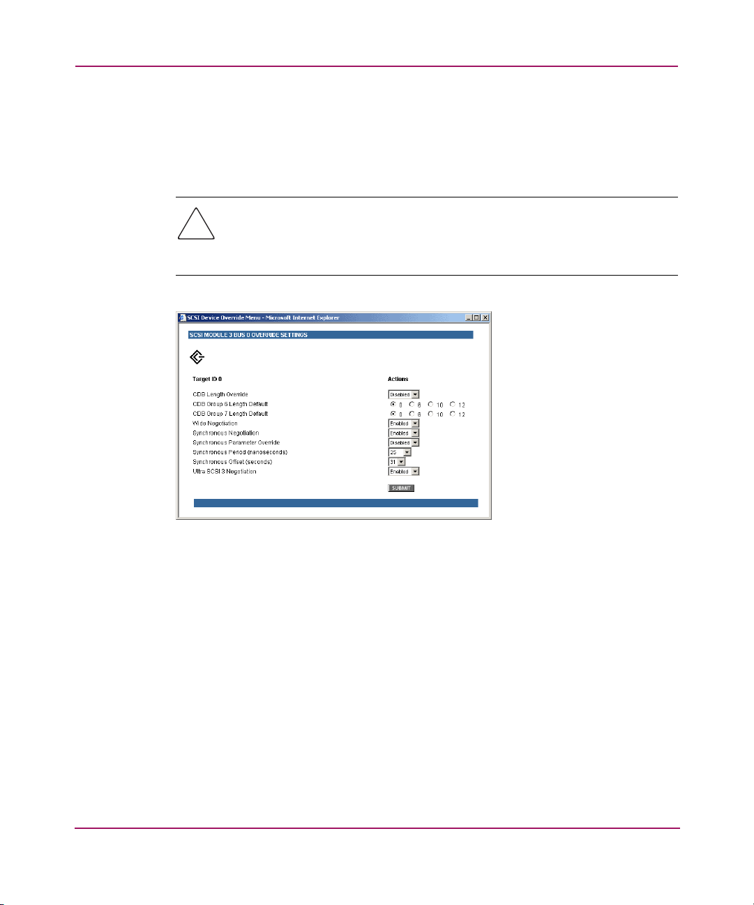
Visual Manager User Interface
■ Override Settings: To override the settings of a SCSI target, select a Target
ID icon with the appropriate Target ID number.
After a specific Target is selected, the SCSI Override sub-screen is displayed
and is used to enter the Override settings (see Figure 48).
Caution: If this configuration setting is incorrectly set, processing difficulties
may occur. Before changing this setting, evaluate the need for the change and
verify the desired setting. HP recommends backing up the router configuration
to an external file before making changes to this setting.
Figure 48: SCSI Device Override screen
■ SCSI bus override settings:
— CDB Length Override enables or disables the override of default CDB
lengths.
— CDB Group 6 Length Default (default: 0) can be set to 0, 6, 10, or 12.
— CDB Group 7 Length Default (default: 0) can be set to 0, 6, 10, or 12.
— Wide Negotiation enables or disables negotiation on a wide SCSI bus.
— Synchronous Negotiation enables or disables synchronous negotiation
on the SCSI bus.
— Synchronous Parameter Override enables or disables parameters for
synchronous negotiation.
90 Network Storage Router M2402 User Guide
Page 85

Visual Manager User Interface
— Synchronous Period (default: 40) sets the maximum number of seconds
allowed for negotiation.
— Synchronous Offset (default: 16) sets the maximum variation in transfer
rate that can be negotiated in megabytes per seconds (MB/s).
— Ultra SCSI-3 Negotiation enables or disables Ultra SCSI-3 support for
the selected Target ID.
When enabled, Ultra SCSI-3 Negotiation helps solve certain
compatibility issues in mixed vendor environments where there may be a
device that cannot handle automatic ne gotiation of the b us speed or where
there is a device that negotiates to use Ultra SCSI-3 but cannot handle the
speed.
91Network Storage Router M2402 User Guide
Page 86

Visual Manager User Interface
Discovery Menu
Accessed from the Main Menu, the Discovery Menu is used to view Target
devices and discover new Target devices (see Figure 49).
Figure 49: Discovery page
In the Discovery Menu, select a specific FC Port or SCSI bus from the Menu Bar
or the router image and then click Go.
92 Network Storage Router M2402 User Guide
Page 87

Mapping Menu
Accessed from the Main Menu, the Mapping Menu is used to view and modify
host and map information for a FC port or SCSI bus. Maps and hosts may be
added, edited, or deleted.
The initial screen display lists all available hosts and the assigned map for the
selected FC port or SCSI bus.
Figure 50 is an example of the initial Mapping screen.
Visual Manager User Interface
Figure 50: Mapping screen
To view or change map settings of a specific module:
1. Select one of the module and port/bus from the menu bar on the left side of
the screen or from the router image at the top of the screen.
2. After a FC port or SCSI bus has been selected, specific mapping information
is displayed, including the name of the port, the selected host, and the
assigned map.
93Network Storage Router M2402 User Guide
Page 88

Visual Manager User Interface
3. To make changes to the configuration, enter the new value and then click
Submit.
Because many mapping configuration settings are common to FC and SCSI maps,
this section is subdivided as follows:
■ Fibre Channel and SCSI Common Mapping Tasks
■ Fibre Channel Mapping Tasks
■ SCSI Mapping Tasks
Fibre Channel and SCSI Common Mapping Tasks
The following action options are available for FC and SCSI maps:
■ Add Host adds a new host.
To add an undefined host, type the host name in the Add Host field and then
click Add.
■ Add Map adds a new map.
T o add an undef ined map, type the name of the map in the Add Map field and
then click Add.
■ Select Host adds a known host.
To select a previously set up host, expand the Select Host drop-down box and
select the host from the list.
■ Select Map adds a known map.
T o select a pre viously set up map, expand the Select Map drop-do wn bo x and
select the map from this list.
■ Delete Host deletes the current host.
Note: ‘Built at runtime’ hosts cannot be deleted.
■ Delete Map deletes the current map.
Note: ‘Indexed’, ‘Auto Assigned’, and ‘SCC’ maps cannot be deleted or renamed.
94 Network Storage Router M2402 User Guide
Page 89

■ Edit/View Host view or change host information.
Viewing and changing Host information is discussed in the following
paragraphs.
■ Edit/View Map view or change map information.
Viewing and changing Map information is discussed in the following
paragraphs.
■ Clone Map makes a copy of the Current map.
Cloning makes it easier to setup new maps with similar information to
previously created maps. The new map must have a unique map ID and name.
Note: SCC and Auto-Assigned maps cannot be cloned.
Fibre Channel Mapping Tasks
Configuration tasks for Fibre Channel mapping include:
■ Viewing and Changing FC Host Information
■ Viewing and Changing FC Map Information
Visual Manager User Interface
Each task is discussed in the following paragraphs.
95Network Storage Router M2402 User Guide
Page 90

Visual Manager User Interface
Viewing and Changing Fibre Channel Host Information
To view or change current host information:
1. In the Mapping Menu screen, select the desired FC module and port.
2. Click Edit/View in the Host section of the screen.
The FC Host Name dialog box is displayed. Current host information is
shown at the top of the dialog box.
3. Enter the new settings and then click Modify.
Figure 51 is an example of the FC Host Name dialog box.
Figure 51: Fibre Channel Host Name dialog box
Fibre Channel Host Name settings:
■ Host Name
■ Host ID (hexadecimal)
■ Port WWN Hi (hexadecimal)
■ Port WWN Lo (hexadecimal)
96 Network Storage Router M2402 User Guide
Page 91

■ Node WWN Hi (hexadecimal)
■ Node WWN Lo (hexadecimal)
■ Map Name
Viewing and Changing Fibre Channel Map Information
To view or change current Fibre Channel map host information:
1. In the Mapping Menu screen, select the desired FC module and port.
2. Click Edit/View in the Map section of the screen.
The FC Map dialog box is displayed. Current map information is sho wn at the
top of the dialog box.
3. Enter the new settings and then click the appropriate action button.
Figure 52 is an example of the Fibre Channel Map dialog box.
Visual Manager User Interface
Figure 52: Fibre Channel Map dialog box
97Network Storage Router M2402 User Guide
Page 92

Visual Manager User Interface
Note: Auto-Assigned and SCC maps cannot be modified, cleared, filled, or have
entries removed.
Note: Map settings are saved to memory when any of the buttons within the page are
selected.
Fibre Channel Map settings:
■ Clear Map clears all entries from the current map.
■ Remove Gaps removes any incremental gaps in the sequence of LUN listed
in the table.
When the system removes gaps from the table, the LUN are renumbered in
sequential order, starting with LUN 0.
Note: Some operating systems require gaps be removed in the mapping table in order
to detect all devices.
■ Fill Map fills in the current map.
To use the Fill Map option, expand the Fill Map Priority drop-down box,
select the fill option, and then click Fill Map.
When the map is filled, the display will show the current devices.
■ Delete deletes map entries.
To delete map entries, expand the Delete Map Item LUN drop-down box,
select the LUN, and then click Delete.
To delete a range of LUNs, select the beginning LUN to delete from the
‘from’ drop-down box and select the last LUN to delete from the ‘to’
drop-down box.
■ Discovered Device Entry adds a discovered device to the map.
To add a discovered device to the map, use the drop-down boxes to enter the
settings, and then click Create Entry in the Discovered Device Entry section
of the screen.
98 Network Storage Router M2402 User Guide
Page 93

■ Manual Device Entry create a map entry for a device that is not yet
discovered or instal led.
To add a new device to the map, use the drop-down boxes to enter the
settings, and then click Create Entry in the Manual Device Entry section of
the screen.
SCSI Mapping Tasks
Configuration tasks for SCSI mapping include:
■ Viewing and Changing SCSI Host Information
■ Viewing and Changing SCSI Map Information
Each task is discussed in the following paragraphs.
Viewing and Changing SCSI Host Information
To view or change current SCSI host information:
1. In the Mapping Menu screen, select the desired SCSI module and bus.
2. Click Edit/View in the Host section of the screen.
The SCSI Host Name dialog box is displayed. Current host information is
shown at the top of the dialog box.
3. Enter the new settings and then click Modify.
Figure 53 is an example of the SCSI Host Name configuration dialog box.
Visual Manager User Interface
Figure 53: SCSI Host Name dialog box
99Network Storage Router M2402 User Guide
Page 94
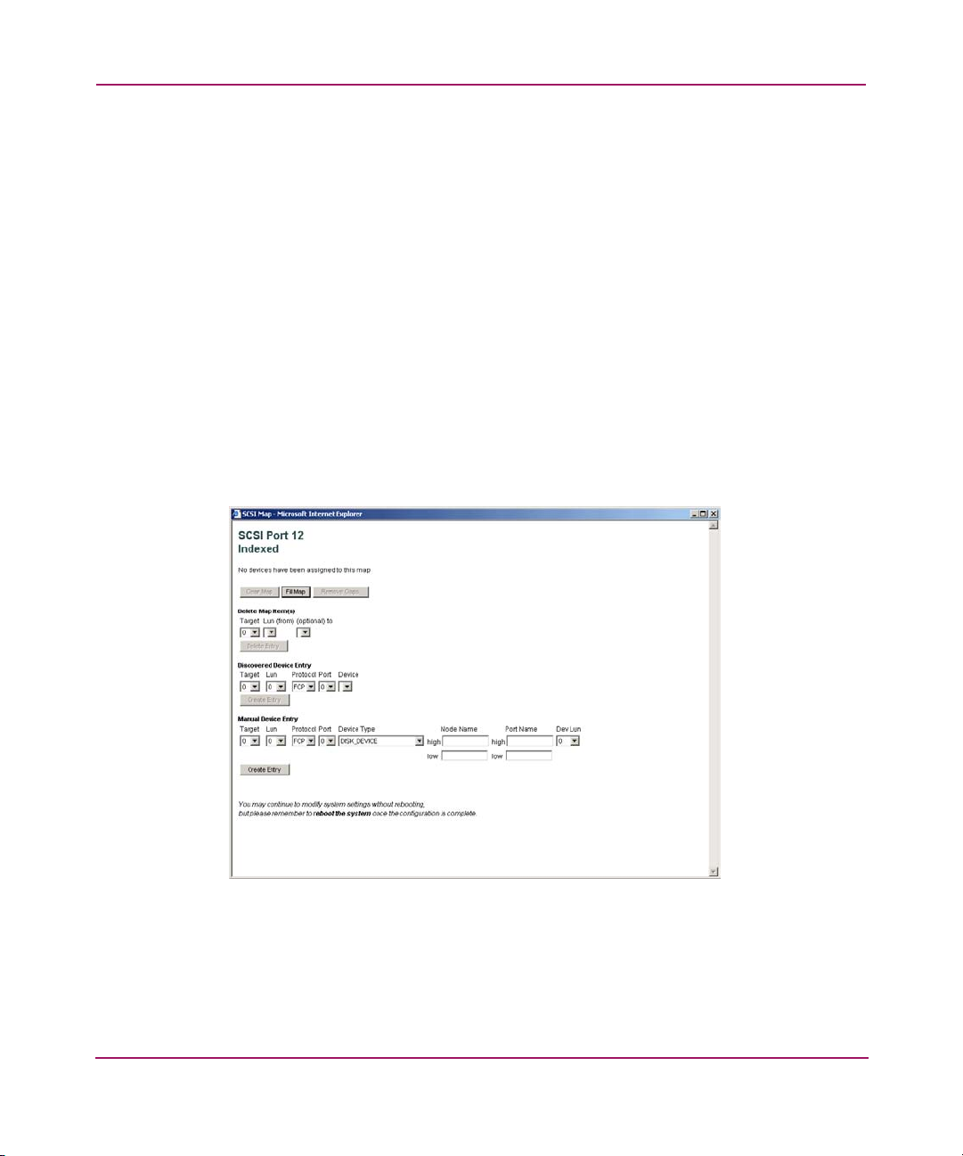
Visual Manager User Interface
SCSI Host Name settings:
■ Host Name
■ Initiator ID
■ Map Name
Viewing and Changing SCSI Map Information
To view or change current SCSI map host information:
1. In the Mapping Menu screen, select the desired SCSI module and bus.
2. Click Edit/View in the Map section of the screen.
The SCSI Map dialog box is displayed. Current map information is shown at
the top of the dialog box.
3. Enter the new settings and then click the appropriate action button.
Figure 54 is an example of the SCSI Map dialog box.
Figure 54: SCSI Map dialog box
100 Network Storage Router M2402 User Guide
Page 95

Visual Manager User Interface
Note: To map Fibre Channel devices to any SCSI initiator on the selected bus, a
Target ID must be enabled from the SCSI Bus Configuration Menu. A Target ID should
only be added if there is a SCSI initiator that needs to address Fibre Channel devices.
Each Target ID can be used to store up to 32 Fibre Channel devices.
\
Note: Auto-Assigned and SCC maps cannot be modified, cleared, filled, or have
entries deleted.
Note: Map settings are saved to memory when any button within the page is selected.
SCSI Map settings:
■ Clear Map clears all entries from the current map.
■ Fill Map fills in the current map.
When the map is filled, the display will show the current devices.
■ Remove Gaps removes any incremental gaps in the sequence of LUN listed
in the table.
When the system removes gaps from the table, the LUN are renumbered in
sequential order, starting with LUN 0.
Note: Some operating systems require gaps be removed in the mapping table to
detect all devices.
■ Delete deletes map entries.
To delete a range of LUNs, select the beginning LUN to delete from the
‘from’ drop-down box and select the last LUN to delete from the ‘to’
drop-down box.
■ Discovered Device Entry adds a discovered device to the map.
To add a discovered device to the map, use the drop-down boxes to enter the
settings, and then click Create Entry in the Discovered Dev ice Ent r y sectio n
of the screen.
101Network Storage Router M2402 User Guide
Page 96

Visual Manager User Interface
■ Manual Device Entry creates a map entry for a device that is not yet
discovered or instal led.
To add a new device to the map, use the drop-down boxes to enter the
settings, and then click Create Entry in the Manual Device Entry section of
the screen.
Note: SCSI maps can be filled or devices can be added to them only when at least
one SCSI Target ID has been enabled in the SCSI bus configuration menu.
102 Network Storage Router M2402 User Guide
Page 97

Statistics Menu
Accessed from the Main Menu, the Statistics Menu is used to display FC port and
SCSI bus information (see Figure 55).
Visual Manager User Interface
Figure 55: Statistics Menu
To view information for a specific module port/bus, click the component on menu
bar or the router image.
To reset the statistics, click Go.
103Network Storage Router M2402 User Guide
Page 98

Visual Manager User Interface
Utilities Menu
Accessed from the Main Menu, the Utilities Menu is used to view and configure
utility options (see Figure 56).
Figure 56: Utilities menu
Utility Menu tasks:
■ Beacon configuration enables the Beacon mode.
■ FTP Utility access opens an FTP session.
■ Trace Settings configuration configures trace settings.
■ Current Traces display shows current trace information.
■ Previous Traces display shows previous trace information.
■ Last Assert Traces display shows last assert trace information.
■ Clear Current Traces clears current trace information.
104 Network Storage Router M2402 User Guide
Page 99

■ Clear Assert Traces clears assert trace information.
■ Event Log Settings configures Event Log settings.
■ Event Log display shows the Event Log.
■ Clear Event Log clears the Event Log.
Each Utility Menu option is discussed in the following sections.
Beacon Mode Configuration
The Beacon Configuration screen is used to enable and disable the router Beacon
mode. When enabled, the Power LED located at the back of the router will
continuously blink, alternating between amber and green (see Figure 57).
To enable the Beacon settings, select the ON checkbox and then click Submit.
Visual Manager User Interface
Figure 57: Beacon configuration screen
Note: When the router is rebooted, beaconing is automatically disabled.
105Network Storage Router M2402 User Guide
Page 100

Visual Manager User Interface
FTP Utility Access
The FTP Utility screen is used to open an FTP session (see Figure 58).
Figure 58: FTP Utility screen
The FTP Utility requires the use of a JAVA applet and prompts for permission to
install the applet, if needed. If the prompt is displayed, follow the onscreen
instructions to complete the installation. The FTP Utility then prompts for
permission to run the applet.
Note: Internet access is required to verify the signature for the HP FTP applet and to
download the JAVA applet plug-in for your browser.
106 Network Storage Router M2402 User Guide
 Loading...