

Page 1

HP 1410 Switch Series Getting Started Guide
HP 1410-24-R Switch (JD986B)
HP 1410-24G-R Switch (JG708A)
Part number:
5998-4635
Document version: 5W100-20130808
Page 2

Legal and notice information
© Copyright 2013 Hewlett-Packard Development Company, L.P.
No part of this documentation may be reproduced or transmitted in any form or by any means without
prior written consent of Hewlett-Packard Development Company, L.P.
The information contained herein is subject to change without notice.
HEWLETT-PACKARD COMPANY MAKES NO WARRANTY OF ANY KIND WITH REGARD TO THIS
MATERIAL, INCLUDING, BUT NOT LIMITED TO, THE IMPLIED WARRANTIES OF MERCHANTABILITY
AND FITNESS FOR A PARTICULAR PURPOSE. Hewlett-Packard shall not be liable for errors contained
herein or for incidental or consequential damages in connection with the furnishing, performance, or
use of this material.
The only warranties for HP products and services are set forth in the express warranty statements
accompanying such products and services. Nothing herein should be construed as constituting an
additional warranty. HP shall not be liable for technical or editorial errors or omissions contained
herein.
Page 3

i
Contents
Product Overview ························································································································································· 1
Preparing for installation ············································································································································· 2
Safety recommendations ·················································································································································· 2
Safety symbols ·························································································································································· 2
General safety recommendations ··························································································································· 2
Electrical safety ························································································································································· 3
Examining the installation site ········································································································································· 3
Temperature/humidity ············································································································································· 3
Cleanness ·································································································································································· 3
ESD prevention ························································································································································· 4
EMI ············································································································································································· 4
Lightning protection ·················································································································································· 5
Installation preparation checklist ····································································································································· 5
Installing the switch ······················································································································································ 7
Mounting the switch in a 19-inch rack with mounting brackets ··················································································· 7
Mounting the switch on a workbench ····························································································································· 8
Connecting cables ···························································································································································· 9
Connecting network cable ······································································································································ 9
Connecting the AC power cord ······························································································································ 9
Verifying the installation ················································································································································ 10
Troubleshooting ·························································································································································· 11
Appendix A Chassis views and technical specifications ························································································ 12
Chassis views ································································································································································· 12
1410-24-R switch ··························································································································································· 13
Front panel ····························································································································································· 13
Rear panel ······························································································································································ 13
1410-24G-R switch ························································································································································ 13
Front panel ····························································································································································· 13
Rear panel ······························································································································································ 14
Technical specifications ················································································································································· 14
Appendix B LEDs ························································································································································ 15
Power LED ······························································································································································ 15
Ethernet copper port LEDs ···································································································································· 15
Support and other resources ····································································································································· 16
Contacting HP ································································································································································ 16
Subscription service ·············································································································································· 16
Related information ························································································································································ 16
Documents ······························································································································································ 16
Websites ································································································································································· 16
Index ··········································································································································································· 88H17
Page 4

1
Product Overview
HP 1410 series switches are unmanaged Fast Ethernet and Gigabit Ethernet switches designed for small
businesses looking for entry-level, low-cost networking solutions with a lifetime warranty. The HP 1410
switch series consists of nine models with flexible mounting options that allow customers to choose the
best switch to meet their network switching needs. All models have QoS support and IEEE 802.3x flow
control features to provide outstanding data efficiency. Simplified plug-and-play operation is enabled by
features like Auto-MDIX and auto-speed negotiation. HP has innovated and combined the latest
advances in silicon technology to provide some of the most power-efficient switches: 1410-16, 1410-24
and 1410-24G-R models are the industry's first IEEE 802.3az compliant unmanaged Fast Ethernet
switches. The available green features, along with the HP lifetime warranty, make the HP 1410 switch
series ideal for customers seeking low-cost and reliable networking solutions.
The HP 1410 Switch Series includes the models in Table 1.
Table 1 HP 1410 Switch Series models
Product code HP description Alias
J9559A HP 1410-8G Switch 1410-8G
J9560A HP 1410-16G Switch 1410-16G
J9561A HP 1410-24G Switch 1410-24G
JD986B HP 1410-24G-R Switch 1410-24G-R
J9661A HP 1410-8 Switch 1410-8
J9662A HP 1410-16 Switch 1410-16
J9663A HP 1410-24 Switch 1410-24
JG708A HP 1410-24-R Switch 1410-24-R
J9664A HP 1410-24-2G Switch 1410-24-2G
This Getting Started Guide covers HP 1410-24-R and 1410-24G-R switches. These models are 24-port
unmanaged Fast Ethernet and Gigabit Ethernet switches with full rackwidth and internal power supply.
Please contact HP local sales for the product availability.
Page 5

2
Preparing for installation
Safety recommendations
W
ARNING!
Before installation and operation, read all of the safety instructions in the
Compliance and Safety Guid
e
supplied with your device.
Safety symbols
When reading this document, note the following symbols:
WARNING means an alert that calls attention to important information that if not understood or
followed can result in personal injury.
CAUTION means an alert that calls attention to important information that if not understood or
followed can result in data loss, data corruption, or damage to hardware or software.
General safety recommendations
To avoid any equipment damage or bodily injury caused by improper use, read the following safety
recommendations before installation. Note that the recommendations do not cover every possible
hazardous condition.
• Do not place the switch on an unstable case or desk. The switch might be severely damaged in case
of a fall.
• Make sure the ground is dry and flat and anti-slip measures are in place.
• Keep the chassis and installation tools away from walk areas.
• Keep the chassis clean and dust-free.
• Do not place the switch near water or place it in a damp environment. Prevent water or moisture
from entering the switch chassis.
• To prevent condensation, unpack the switch at least half an hour after you move the switch from a
location below 0°C (32°F) to the equipment room. Power on the switch at least 2 hours after you
move the switch from a location below 0°C (32°F) to the equipment room.
• Ensure proper ventilation of the equipment room, and keep the air inlet and outlet vents of the switch
free of obstruction.
• Make sure the operating voltage is in the required range.
• Use a screw driver to fasten screws.
Page 6

3
Electrical safety
• Carefully examine your work area for possible hazards, like moist floors, ungrounded power
extension cables, or missing safety grounds.
• Locate the emergency power-off switch in the room before installation. Shut off the power
immediately if an accident occurs.
• Unplug all the external cables (including power cables) before moving the chassis.
• Do not work alone when you operate the switch with the switch powered on.
• Always check that the power has been disconnected when you perform operations that require the
switch to be powered off.
Examining the installation site
The HP 1410 switches must be used indoors. To ensure correct operation and a long lifespan for your
switch, the installation site must meet the requirements in this section.
Temperature/humidity
Maintain appropriate temperature and humidity in the equipment room.
• Lasting high relative humidity can cause poor insulation, electric creepage, mechanical property
change of materials, or metal corrosion.
• Lasting low relative humidity can cause washer contraction and ESD, and can cause problems
including loose captive screws and circuit failure.
• High temperature can accelerate the aging of insulation materials and significantly lower the
reliability and lifespan of the switch.
Maintain temperature and humidity in the equipment room, as described in Table 2.
Table 2 Temperature/
humidity requirements in the equipment room
Temperature Relative humidity
0°C to 45°C (32°F to 113°F) 5% to 95%, noncondensing
Cleanness
Dust buildup on the chassis might result in electrostatic adsorption. Electrostatic adsorption causes poor
contact of metal components or contact points, especially when indoor relative humidity is low. In the
worst case, electrostatic adsorption can cause communication failure.
To ensure correct operation, the equipment room must meet the dust concentration requirements listed
in Table 3.
Page 7

4
Table 3 Dust concentration limit in the equipment room
Substance Concentration limit (particles/m³)
Dust ≤ 3 × 10⁴ (no visible dust on the tabletop over three days)
NOTE:
Dust diameter ≥ 5 μm
The equipment room must also meet strict limits on salts, acids, and sulfides, as shown in Table 4, to
eliminate corrosion and premature aging of components.
Table 4 Harmful gas limits in the equipment room
Gas Maximum concentration (mg/m³)
SO2 0.2
H2S 0.006
NH3 0.05
Cl2 0.01
ESD prevention
To prevent electrostatic discharge (ESD), follow these guidelines:
• Ground the switch correctly.
• Take dust-proof measures for the equipment room.
• Maintain the humidity and temperature at a proper level.
• Always wear an ESD-preventive wrist strap. Make sure the wrist strap makes skin contact and is well
grounded.
NOTE:
The ESD-preventive wrist strap is not provided with the switch. Order it yourself.
EMI
All electromagnetic interference (EMI) sources, from outside or inside of the switch and application
system, adversely affect the switch in the following conduction patterns:
• Capacitance coupling
• Inductance coupling
• Electromagnetic wave radiation
• Common impedance (including the grounding system) coupling
• Cables (power cords, signal cables, and output cables)
To prevent EMI:
• If the AC power supply system is a TN system, use a single-phase three-wire power receptacle with
protection earth (PE) to filter interference from the power grid.
Page 8

5
• Keep the switch far away from radio transmitting stations, radar stations, and high-frequency
devices.
• Use electromagnetic shielding, for example, shielded interface cables, when necessary.
• Route interface cables indoors.
Lightning protection
To better protect the switch from lightning, follow these guidelines:
• Make sure the grounding cable of the chassis is well grounded.
• Make sure the grounding terminal of the AC power receptacle is well grounded.
Installation preparation checklist
Table 5 Installation preparation checklist
Item Requirements Result
Installation
site
Ventilation
• There is a minimum clearance of 10 cm (3.9 in) around
the inlet and outlet vents for heat dissipation of the switch
chassis.
• A ventilation system is available at the installation site.
Temperature 0°C to 45°C (32°F to 113°F)
Relative humidity 5% to 95% (noncondensing)
Cleanness
• Dust concentration ≤ 3 × 10⁴ particles/m3
• No dust on desk within three days.
ESD prevention
• The equipment and rack are well grounded.
• The equipment room is dust-proof.
• The humidity and temperature are at a proper level.
• Wear an ESD-preventive wrist strap. Make sure the wrist
strap makes good skin contact and is well grounded.
EMI prevention
• Take effective measures to protect the power system from
the power grid system.
• Separate the protection ground of the switch from the
grounding device or lightning protection grounding
device as far as possible.
• Keep the switch far away from radio stations and radar
and high-frequency devices working in high current.
• Use electromagnetic shielding when necessary.
Lightning
protection
• The grounding cable of the chassis is well grounded.
• The grounding terminal of the AC power receptacle is
well grounded.
Electricity safety
• Equip a UPS.
• In case of emergency during operation, switch off the
external power switch.
Page 9

6
Item Requirements Result
Rack-mounting
requirements
• Install the switch in an open rack if possible. If you install
the switch in a closed cabinet, make sure that the cabinet
is equipped with a good ventilation system.
• The rack is sturdy enough to support the weight of the
switch and installation accessories.
• The size of the rack is appropriate for the switch.
• The front and rear of the rack are at least 0.8 m (31.50 in)
away from walls or other devices.
Safety
precautions
• The switch is far away from any moist area and heat source.
• You have located the emergency power switch in the equipment room.
Accessories Accessories shipped with the switch
Reference
• Documents shipped with the switch.
• Online documents.
Page 10
7
Installing the switch
The HP 1410 switch can be installed in a 19-inch rack or on a workbench. The installation procedures for
the HP 1410-24-R switch and the HP 1410-24G-R switch are the same. The following installation
procedure uses the HP 1410-24-R switch as an example.
W
ARNING!
Before installing or moving the switch, remove the power cord.
Mounting the switch in a 19-inch rack with
mounting brackets
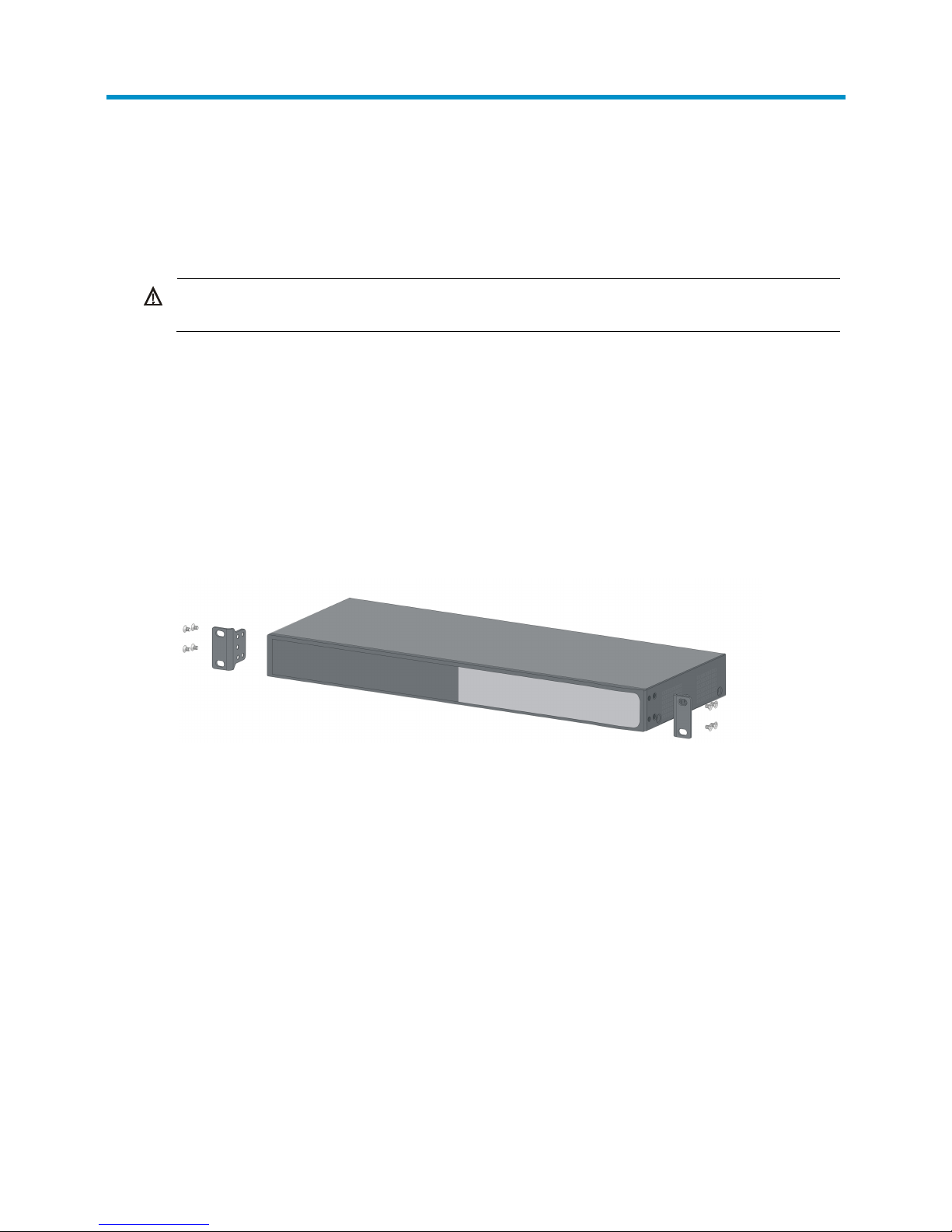
To install the switch with mounting brackets:
1. Wear an ESD-preventive wrist strap, and make sure the rack is securely grounded and is stable.
2. Attach the mounting brackets on the sides of the front panel with screws.
Figure 1 Installing the mounting brackets to the HP 1410-24-R switch
3. Place the switch on a holder in the rack, and push in the switch along the guide rails until the oval
holes in the brackets align with the mounting holes in the rack posts.
4. Attach the mounting brackets to the rack posts with screws.
Page 11

8
Figure 2 Mounting the HP 1410-24-R switch in the rack
NOTE:
The mounting brackets are used only for attaching the switch instead of bearing the switch weight. A
holder on the rack is used to hold (bear the weight of) the switch.
Mounting the switch on a workbench
IMPORTANT:
• Ensure good ventilation and 10 cm (3.9 in) of clearance around the chassis for heat dissipation.
• Avoid placing heavy objects on the switch.
To mount the switch on a workbench:
1. Make sure the workbench is securely grounded and is stable.
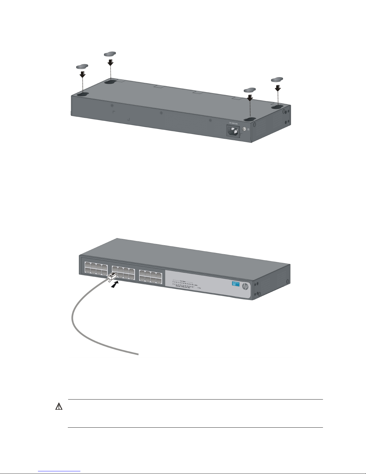
2. Place the switch upside down, and clean the round holes on the bottom of the chassis with a dry
cloth.
3. Attach the rubber feet to the four round holes on the bottom of the chassis.
4. Place the switch with right side up on the workbench.
Page 12
9
Figure 3 Attaching rubber feet
Connecting cables
Connecting network cable
Use crossover cables or straight-through cables to connect a PC or other network devices to the Ethernet
port of the switch.
Figure 4 Connecting network cable
Connecting the AC power cord
W
ARNING!
Make sure the grounding cable is securely connected and the switch is well grounded before connectin
g
the AC power cord.
Page 13

10
1. Make sure the correct power source is used.
2. Connect one end of the AC power cord to the AC-input power receptacle on the switch.
3. Connect the other end of the AC power cord to the AC power outlet.
4. Check the Power LED.
If it is ON, it means the power connection is correct.
Verifying the installation
After you complete the installation, verify that:
• There is enough space for heat dissipation around the switch, and the rack or workbench is stable.
• The grounding cable is securely connected.
• The correct power source is used.
• All the interface cables are cabled indoors.
Page 14

11
Troubleshooting
This chapter lists issues and solutions while using and managing the switch. If you encounter an issue that
is not listed and you cannot solve it, contact HP Technical Support.
Table 6 Troubleshooting
Symptom Troubleshooting method
Power LED off
1. Verify that the correct power source is used and the power cords
are correctly connected.
2. Verify that the power source side provides power supply correctly.
LAN interface LED off
1. Verify that the network cable is correctly connected to the network
port of the switch.
2. Plug the two ends of a network cable into two network ports of the
switch. If the port LEDs are on, it indicates that the network cable is
operating correctly. Otherwise, replace the network cable.
Page 15

12
Appendix A Chassis views and technical
specifications
Chassis views
The HP1410 Switch Series includes the models in Table 7. For availability information about the models,
contact HP sales.
Table 7 HP 1410 Switch Series models
Product code HP description Alias
JD986B HP 1410-24-R Switch 1410-24-R
JG708A HP 1410-24G-R Switch 1410-24G-R
IMPORTANT:
For regulatory identification purposes, the HP 1410 Switch Series products are assigned Regulatory
Model Numbers (RMN). The Regulatory Model Numbers for these products are listed below. These
regulatory numbers should not be confused with the marketing names HP 1410, or product numbers
J
D986B and JG708A
Table 8 Regulatory Model Numbers in the HP 1410 Switch Series
Product code RMN HP description
JD986B HNGZA-HA0006 HP 1410-24-R Switch
JG708A HNGZA-HA0007 HP 1410-24G-R Switch
NOTE:
The figures in this document are for illustration only.
Page 16

13
1410-24-R switch
Front panel
Figure 5 1410-24-R front panel
(1) 10/100Base-TX port (2) Port LED (3) Power LED (Power)
Rear panel
Figure 6 1410-24-R rear panel
(1) Grounding screw (2) AC-input power receptacle
1410-24G-R switch
Front panel
Figure 7 1410-24G-R front panel
(1) 10/100/1000Base-T port (2) Port LED (3) Power LED (Power)
Page 17

14
Rear panel
Figure 8 1410-24G-R rear panel
(1) Grounding screw (2) AC-input power receptacle
Technical specifications
Table 9 Technical specifications
Item 1410-24-R 1410-24G-R
Dimensions (H × W × D)
44 × 440 × 173 mm (1.73 × 17.32
× 6.81 in)
44 × 440 × 173 mm (1.73 × 17.32 ×
6.81 in)
Weight ≤ 2.5 kg (5.51 lb) ≤ 3 kg (6.61 lb)
Ethernet port 24 × 10/100Base-TX ports 24 × 10/100/1000Base-T ports
Input AC voltage Rated voltage range: 100 VAC to 240 VAC @ 50 Hz or 60 Hz
Power consumption (full
configuration)
< 6 W < 16 W
Operating temperature 0°C to 40°C (32°F to 104°F)
Relative humidity 5% to 95%, noncondensing
Cooling system No fans for heat ventilation
Page 18

15
Appendix B LEDs
The LEDs on the front panel show the operation status of the switch.
Power LED
Table 10 Power LED description
LED Status Description
Power
Steady green The switch is operating correctly.
Flashing green The system is performing power-on self-test (POST).
Off The switch is powered off or the power supply has failed.
Ethernet copper port LEDs
Table 11 Ethernet copper port LEDs
LED Status Description
Link/Act
10/100BASE-TX port
Steady green The port is operating at 10/100 Mbps.
Flashing green
The port is sending or receiving data at
10/100 Mbps.
Off No link is present on the port.
10/100/1000BASE-T
port
Steady green The port is operating at 1000 Mbps.
Flashing green
The port is sending or receiving data at 1000
Mbps.
Steady yellow The port is operating at 10/100 Mbps.
Flashing yellow
The port is sending or receiving data at
10/100 Mbps.
Off No link is present on the port.
Page 19

16
Support and other resources
Contacting HP
For worldwide technical support information, see the HP support website:
http://www.hp.com/support
Before contacting HP, collect the following information:
• Product model names and numbers
• Technical support registration number (if applicable)
• Product serial numbers
• Error messages
• Operating system type and revision level
• Detailed questions
Subscription service
HP recommends that you register your product at the Subscriber's Choice for Business website:
http://www.hp.com/go/wwalerts
After registering, you will receive email notification of product enhancements, new driver versions,
firmware updates, and other product resources.
Related information
Documents
To find related documents, browse to the Manuals page of the HP Business Support Center website:
http://www.hp.com/support/manuals
• For related documentation, navigate to the Networking section, and select a networking category.
• For a complete list of acronyms and their definitions, see HP FlexNetwork Technology Acronyms.
Websites
• HP.com http://www.hp.com
• HP Networking http://www.hp.com/go/networking
• HP manuals http://www.hp.com/support/manuals
• HP download drivers and software http://www.hp.com/support/downloads
• HP software depot http://www.software.hp.com
• HP Education http://www.hp.com/learn
Page 20

17
Index
A
AC
power cord connection, 9
Appendix A (Chassis views and technical
specifications), 12
Appendix B (LEDs), 15
C
cable
network cable connection, 9
checklist (pre-installation), 5
cleanness (installation site), 3
connecting
AC power cord, 9
network cables, 9
D
dust (installation site), 3
E
electricity
AC power cord connection, 9
electromagnetic interference. Use EMI
electrostatic discharge. Use ESD
EMI prevention, 4
ESD prevention, 4
safety recommendations, 3
EMI prevention, 4
environment
installation site, 3
site cleanness, 3
site dust concentration, 3
site gas saturation, 3
site humidity, 3
site temperature, 3
ESD prevention, 4
examining installation site, 3
G
gas (installation site), 3
grounding
EMI prevention, 4
ESD prevention, 4
lightning protection, 5
H
hardware
rack switch mount, 7
switch installation, 7
workbench switch mount, 8
hardware management/maintenance
chassis technical specifications, 12
chassis views, 12
LEDs, 15
humidity
installation site requirements, 3
I
installing
checklist, 5
EMI prevention, 4
ESD prevention, 4
installation verification, 10
lightning protection, 5
site cleanness, 3
site examination, 3
site humidity, 3
site temperature, 3
switch, 7
L
lightning
protection, 5
M
mounting
rack switch mount, 7
workbench switch mount, 8
N
network cable connection, 9
network management
chassis technical specifications, 12
chassis views, 12
Page 21

18
LEDs, 15
P
power supply
AC power cord connection, 9
preparing for installation, 2
preventing
EMI prevention, 4
ESD prevention, 4
procedure
connecting AC power cord, 9
connecting network cables, 9
installing switch, 7
mounting switch in rack, 7
mounting switch on workbench, 8
verifying installation, 10
R
rack switch mount, 7
S
safety
caution and warning symbols, 2
electrical safety recommendations, 3
EMI prevention, 4
ESD prevention, 4
general recommendations, 2
installation site cleanness, 3
installation site dust concentration, 3
installation site gas saturation, 3
installation site humidity, 3
installation site temperature, 3
lightning protection, 5
site
cleanness, 3
dust concentration, 3
examination, 3
gas saturation, 3
humidity, 3
temperature, 3
switch
AC power cord connection, 9
installation, 7
installation verification, 10
network cable connection, 9
rack switch mount, 7
workbench switch mount, 8
T
temperature
installation site requirements, 3
V
verifying installation, 10
W
workbench switch mount, 8
 Loading...