

Page 1
2.4 GHz and 5 GHz Outdoor 3-Port MIMO Omnidirectional Antennas (J9719A and J9720A) Guide
SAFETY
The HP J9719A and J9720A and all associated equipment should be
installed in accordance with applicable local and national electrical code
guidelines to ensure safe operation.
Before connecting an outdoor antenna to an HP Wireless Access
Point, be sure that the access point radio power levels are set in
accordance with local regulatory requirements. For information
on setting radio power levels, see Transmit power control in the
MSM3xx/4xx Access Points Management and Configuration Guide.
For mandatory antenna power settings by country/region,
look for Antenna Power-Level Setting Guide (for MSM products)
at www.hp.com/support/manuals (search by antenna part number).
Please read all instructions carefully before attempting to install
and use this product.
Grounding: System grounding and lightning protection are essential,
especially for exterior-mounted antennas exposed to the elements.
Never install an antenna where it may fall and contact electrical lines.
wArrAnTY And SupporT inFormATion
See the warranty and support information included with this product. For
the latest information go to www.hp.com/networking/support.
© Copyright 2011, Hewlett-Packard Development Company, L.P.
The information contained herein is subject to change without notice.
Printed in Malaysia,
October 2011
Part Number: 5998-2272
Image of J9719A and J9720A
dESCripTion
The HP J9719A and J9720A are single-band omnidirectional antennas
for use in 802.11n MIMO applications. Enclosed in a weatherproof,
rugged radome, these antennas include a mast mount for outdoor
deployment. Each of the three MIMO antenna elements are connected
to the access point via low loss, outdoor rated coaxial pigtails. The
radiation patterns are uniform and symmetrical, providing excellent
signal level into defined coverage areas.
These antennas will enhance the performance of 802.11n systems.
SpECiFiCATionS
Item J9719A J9720A
Frequency 2400 MHz - 2500 MHz 5150 MHz - 5875 MHz
Gain 6 dBi 8 dBi
Polarization Linear, Vertical
3dB Beamwidth 26° 15.5°
VSWR 2:1, Max
Impedance 50 Ω
Power 5W x 3
Port-to-port Isolation 22 dB
Downtilt 0°
Cable Length 91 cm (36”) x 3
RF Connector Type N, Male (x 3)
Cable Type RG58, Low Temp. Plenum rated
Radome Material Polycarbonate, White
Size
Weight 1.51 kg (3.32 lbs) 1.53 kg (3.37 lbs)
Mounting
Wind Surface Area
(Curvature)
Wind Survival 200 km/h (125 mph)
Wind Gust Survival 266 km/h (165 mph)
Operational Temperature
Storage Temperature
Ingression Protection IP67
248 mm height x 210 mm diameter,
(9.76” x 8.27”), not including brackets
Mast Mount 31.8 mm - 57.2 mm diam.
(1.25” - 2.25” diam.)
2
0.03 m
(0.328 sq. ft)
-40°C to +70°C
(Cable Install Low Temp -20°C)
-40°C to +85°C
Page 2
AnTEnnA loCATion
ligHTning ArrESTEr
This is an outdoor antenna, but it may also be used indoors. For best
results, mount the J9719A or J9720A in the center of the coverage area.
A line-of-sight path between the antenna and active area works best.
Avoid mounting next to a column or vertical support that could create a
shadow zone and reduce coverage.
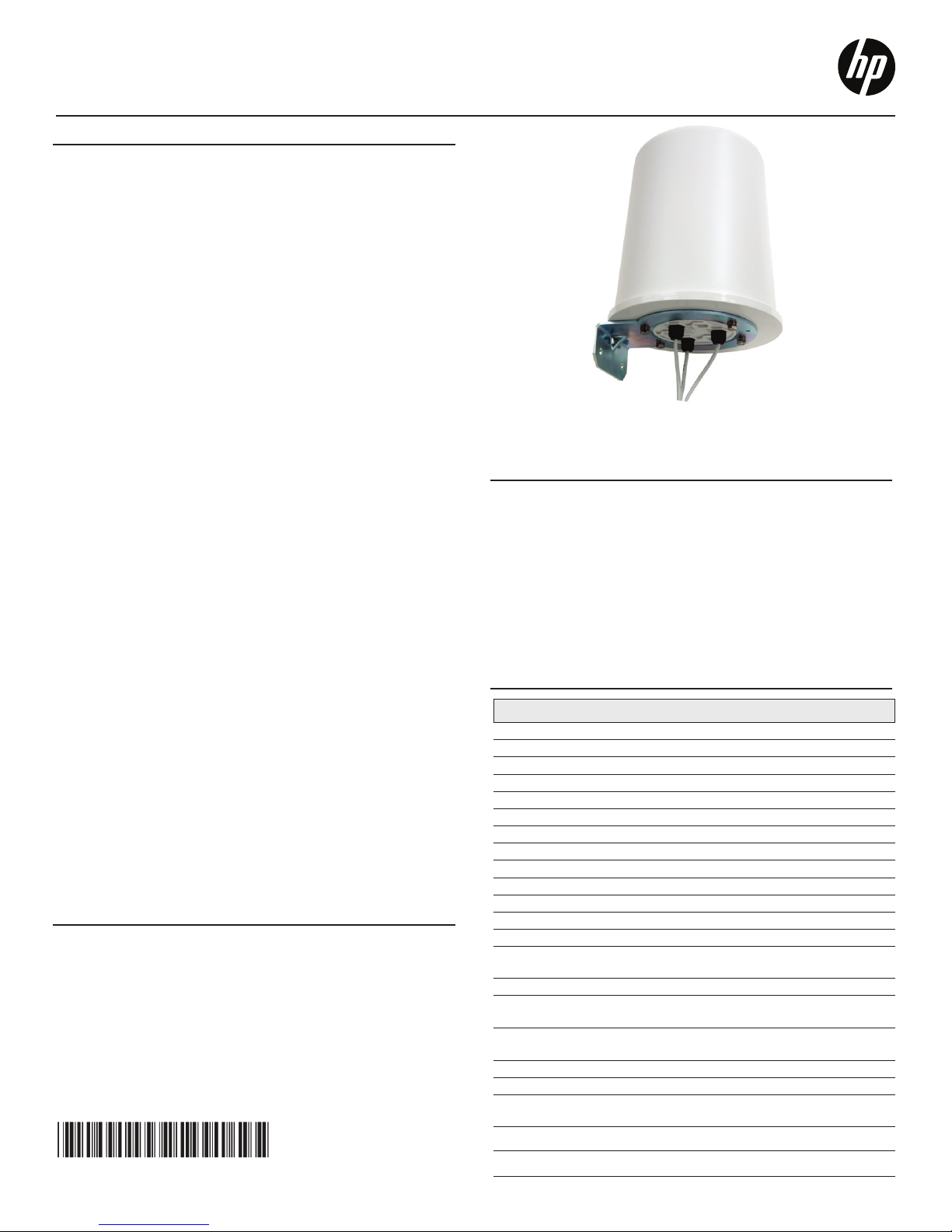
ASSEmblY And mounTing
The kit allows mounting on a mast (1¼ - 2¼ inches). Assemble and
mount the antenna as follows.
1
5
5
4
2
6
3
WARNING: PROFESSIONAL INSTALLATION REQUIRED: Prior
to installing or using this device, consult with a professional installer
trained in RF installation and knowledgeable in local regulations
including building and wiring codes, safety, channel, power, indoor/
outdoor restrictions, and license requirements for the intended country.
It is the responsibility of the end user to ensure that installation and use
comply with local safety and radio regulations.
Warning: Surge protection and grounding: When connecting an
outdoor antenna, make sure that proper lightning surge protection and
grounding precautions are taken in accordance with local electrical
codes. Failure to do so may result in personal injury, fire, equipment
damage, or a voided warranty. The HP hardware warranty does not
cover damage caused by static discharge or lightning strike.
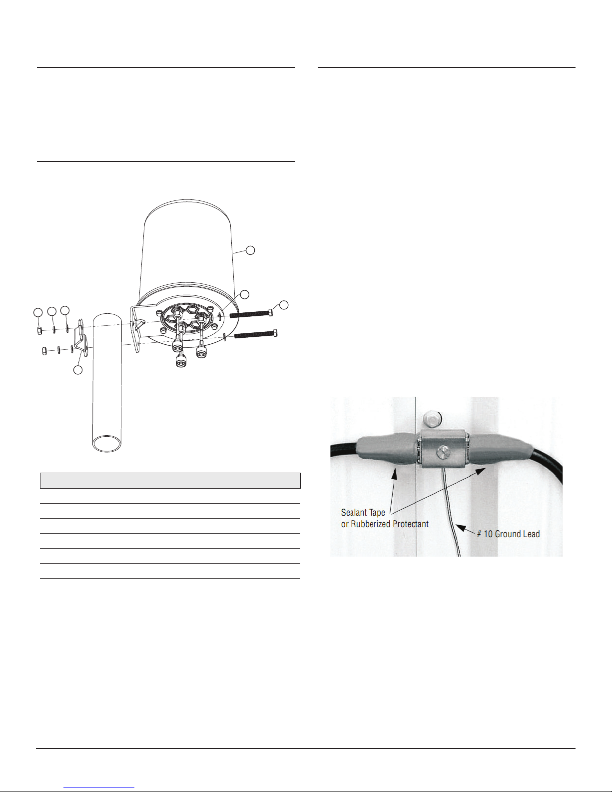
For outdoor applications, it is strongly recommended that you install
a lightning arrester (HP J8996A or equivalent) for each port of the
antenna. Lightning arresters must be purchased separately.
For best results, install the lightning arrester in close proximity to a lowresistance ground at a point where the coaxial cable enters the building
or attaches to an AP. For exterior installations, use weatherproof coaxial
connectors with a suitable plastic or rubberized tape to prevent water
incursion. See Photo 2.
To connect the lightning arrester to the ground, use a very short and
direct run of # 10 solid copper wire, or equivalent. Ensure that the other
end of the grounding wire connects to a true earth ground according to
the NFPA 70 National Electrical Code and/or all pertinent local codes.
Key Description Qty
1 Antenna Assembly 1
2 Nut, Hex, [M8x1.25], Ss, Pa 2
3 Bolt, Hex, M8x1.25 x 80 mm, Ss, Pa 2
4 Washer, Slock, [M8], Ss, Pa 2
5 Washer, Flat, [M8], Ss, Pa 4
6 Bracket, Rear Clamp 1
1. Locate unit on mast, so that antenna is just above
metal pole structure.
2. Locate rear clamp bracket just behind antenna bracket
and align holes.
3. Insert (2) M8 bolts using flat washers on the front side,
as image shows.
4. Place (2) M8 flat washers, (2) lock washers and (2) nuts on
the back of the (2) bolts, securing the antenna in place.
5. Torque nuts to 15-17N-m (11.0-12.5 ft-lbf)
Photo 2.
2.4 GHz and 5 GHz Outdoor 3-port MIMO Omnidirectional Antennas (J9719A and J9720A) Guide2
Page 3
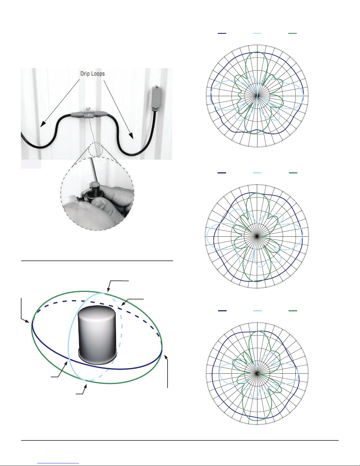
Be sure to install the lightning arrester in an accessible location that
P1 2.45
P2 2.45
P3 2.4-2.5 GHz.NSI
permits periodic inspection and replacement (as needed).
Provide drip loops in cables to prevent water from entering the building.
See Photo 3.
2.45 GHz (Port 1 Vertical Polarization)
0
350
340
330
320
310
300
290
280
270
260
250
240
230
220
210
200
190
180
E90 PlaneE0 PlaneH Plane
10
20
30
-20 -10 0
150
160
170
40
50
60
70
80
90
dB
100
110
120
130
140
Photo 3.
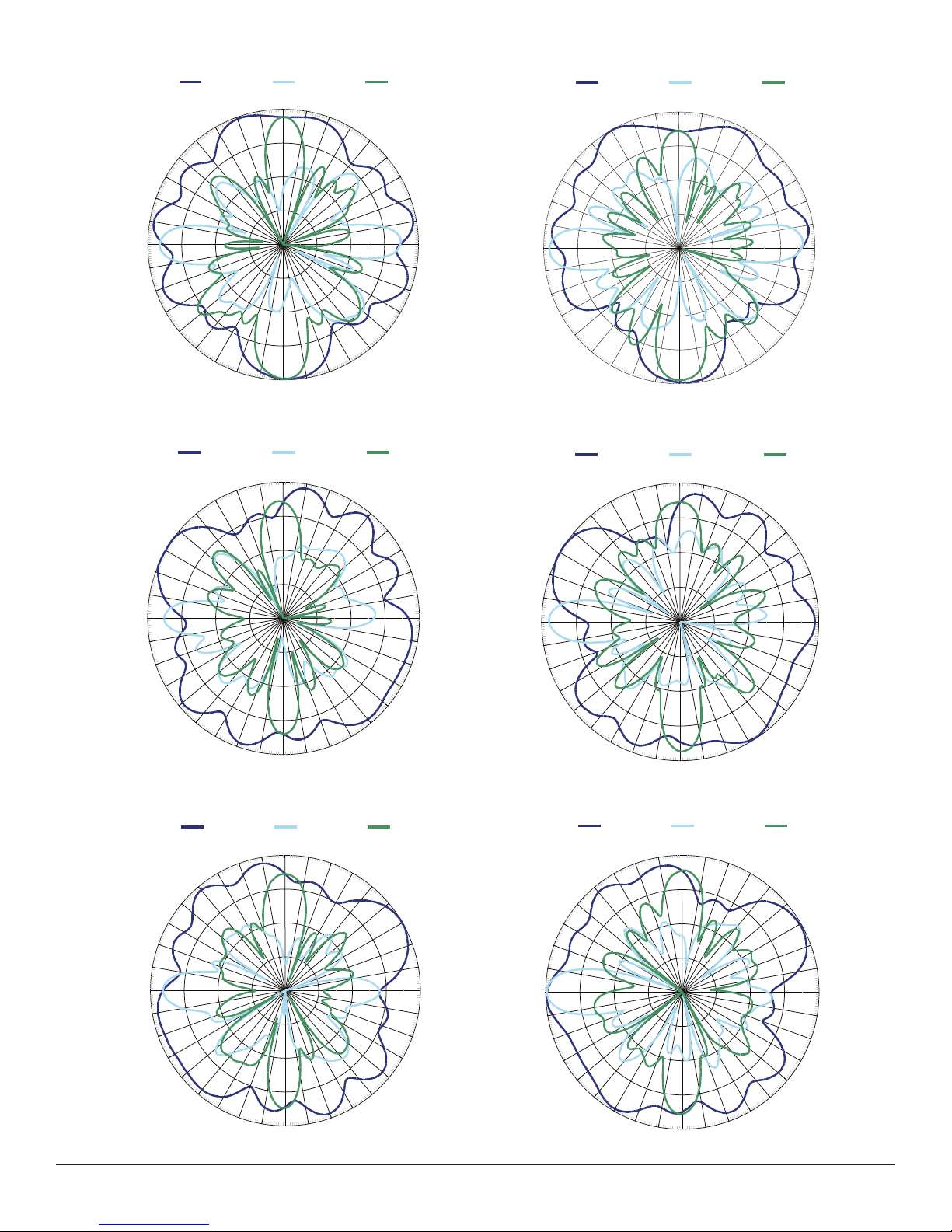
AnTEnnA pATTErn ploTS
The plots on the following pages are oriented as follows:
H-Plane 90°
E0-Plane 90°
H-Plane 0°
E90-Plane 270°
E0-Plane 180°
E90-Plane 180°
Plot Orientation Diagram
E90-Plane 0°
E0-Plane 0°
E90-Plane 90°
E0-Plane 270°
H-Plane 180°
H-Plane 270°
2.45 GHz (Port 2 Vertical Polarization)
0
350
340
330
320
310
300
290
280
270
260
250
240
230
220
210
200
190
180
2.45 GHz (Port 3 Vertical Polarization)
0
350
340
330
320
310
300
290
280
270
260
250
240
230
220
210
200
190
180
E90 PlaneE0 PlaneH Plane
10
20
30
-20 -10 0
150
160
170
E90 PlaneE0 PlaneH Plane
10
20
30
-20 -10 0
150
160
170
40
50
60
70
80
90
dB
100
110
120
130
140
40
50
60
70
80
90
dB
100
110
120
130
140
2.4 GHz and 5 GHz Outdoor 3-port MIMO Omnidirectional Antennas (J9719A and J9720A) Guide3
Page 4
0
350
340
330
320
310
300
290
280
270
260
250
240
230
220
210
200
190
180
170
160
150
140
130
120
110
100
90
80
70
60
50
40
30
20
10
-20 -10 0
dB
P1 2.45
0
350
340
330
320
310
300
290
280
270
260
250
240
230
220
210
200
190
180
170
160
150
140
130
120
110
100
90
80
70
60
50
40
30
20
10
-20 -10 0
dB
P1 5.47
P1 5.725
E90 PlaneE0 PlaneH Plane
E90 PlaneE0 PlaneH Plane
0
350
340
330
320
310
300
290
280
270
260
250
240
230
220
210
200
190
180
170
160
150
140
130
120
110
100
90
80
70
60
50
40
30
20
10
-20 -10 0
dB
P1 2.45
P1 5.47
E90 PlaneE0 PlaneH Plane
E90 PlaneE0 PlaneH Plane
E90 PlaneE0 PlaneH Plane
0
350
340
330
320
310
300
290
280
270
260
250
240
230
220
210
200
190
180
170
160
150
140
130
120
110
100
90
80
70
60
50
40
30
20
10
-20 -10 0
dB
P2 2.45
0
350
340
330
320
310
300
290
280
270
260
250
240
230
220
210
200
190
180
170
160
150
140
130
120
110
100
90
80
70
60
50
40
30
20
10
-20 -10 0
dB
P2 5.47
P2 5.725
E90 PlaneE0 PlaneH Plane
0
350
340
330
320
310
300
290
280
270
260
250
240
230
220
210
200
190
180
170
160
150
140
130
120
110
100
90
80
70
60
50
40
30
20
10
-20 -10 0
dB
P2 2.45
P2 5.47
E90 PlaneE0 PlaneH Plane
E90 PlaneE0 PlaneH Plane
0
350
340
330
320
310
300
290
280
270
260
250
240
230
220
210
200
190
180
170
160
150
140
130
120
110
100
90
80
70
60
50
40
30
20
10
-20 -10 0
dB
0
350
340
330
320
310
300
290
280
270
260
250
240
230
220
210
200
190
180
170
160
150
140
130
120
110
100
90
80
70
60
50
40
30
20
10
-20 -10 0
dB
P3 5.725
P3 5.47
P3 2.4-2.5 GHz.NSI
E90 PlaneE0 PlaneH Plane
0
350
340
330
320
310
300
290
280
270
260
250
240
230
220
210
200
190
180
170
160
150
140
130
120
110
100
90
80
70
60
50
40
30
20
10
-20 -10 0
dB
P3 5.47
P3 2.4-2.5 GHz.NSI
5.725 GHz (Port 1 Vertical Polarization)5.47 GHz (Port 1 Vertical Polarization)
E0 PlaneH Plane
0
350
340
330
310
300
290
250
240
230
300
290
250
240
300
290
280
270
260
250
240
320
220
210
330
320
310
230
220
210
330
320
310
230
220
210
200
190
350
340
200
190
350
340
200
190
280
270
260
280
270
260
10
170
180
E0 PlaneH Plane
0
10
170
180
E0 PlaneH Plane
0
180
E90 Plane
20
30
-20 -10 0
150
160
E90 Plane
20
30
-20 -10 0
150
160
E90 Plane
10
20
30
-20 -10 0
150
160
170
E0 PlaneH Plane
0
350
340
40
50
60
70
80
90
dB
100
110
120
130
140
300
290
280
270
260
250
240
330
320
310
230
220
210
200
190
10
170
180
E90 Plane
20
30
40
-20 -10 0
140
150
160
50
60
70
80
90
dB
100
110
120
130
5.725 GHz (Port 2 Vertical Polarization)5.47 GHz (Port 2 Vertical Polarization)
E0 PlaneH Plane
0
350
340
40
50
60
70
80
90
dB
100
110
120
130
140
300
290
280
270
260
250
240
330
320
310
230
220
210
200
190
10
170
180
E90 Plane
20
30
40
-20 -10 0
140
150
160
50
60
70
80
90
dB
100
110
120
130
5.725 GHz (Port 3 Vertical Polarization)5.47 GHz (Port 3 Vertical Polarization)
E0 PlaneH Plane
0
350
340
40
50
60
70
80
90
dB
100
110
120
130
140
300
290
280
270
260
250
240
330
320
310
230
220
210
200
190
10
170
180
E90 Plane
20
30
40
-20 -10 0
140
150
160
50
60
70
80
90
dB
100
110
120
130
2.4 GHz and 5 GHz Outdoor 3-port MIMO Omnidirectional Antennas (J9719A and J9720A) Guide4
 Loading...