

HP ProCurve J8161A, ProCurve 600, J8169A, ProCurve 610, J8168A Installation And Getting Started Manual
Page 1
Installation and
Getting Started Guide
HP ProCurve
600/610 External
Power Supplies
www.hp.com/go/hpprocurve
PoE
Power over Ethernet Devices
Page 2

Page 3

HP ProCurve 600/610
External Power Supplies
Installation and Getting Started Guide
Page 4

© Copyright 2004 Hewlett-Packard Development Company, L.P. The information contained herein is subject
to change without notice.
This document contains proprietary information, which is
protected by copyright. No part of this document may be
photocopied, reproduced, or translated into another
language without the prior written consent of HewlettPackard.
Publication Number
5990-8800
August 2004
Applicable Products
HP ProCurve 600 Redundant and
External Power Supply (J8168A)
HP ProCurve 610 External Power Supply (J8169A)
Disclaimer
HEWLETT-PACKARD COMPANY MAKES NO WARRANTY
OF ANY KIND WITH REGARD TO THIS MATERIAL,
INCLUDING, BUT NOT LIMITED TO, THE IMPLIED
WARRANTIES OF MERCHANTABILITY AND FITNESS
FOR A PARTICULAR PURPOSE. Hewlett-Packard shall not
be liable for errors contained herein or for incidental or
consequential damages in connection with the furnishing,
performance, or use of this material.
The only warranties for HP products and services are set
forth in the express warranty statements accompanying
such products and services. Nothing herein should be
construed as constituting an additional warranty. HP shall
not be liable for technical or editorial errors or omissions
contained herein.
Hewlett-Packard assumes no responsibility for the use or
reliability of its software on equipment that is not furnished
by Hewlett-Packard.
Warranty
See the Customer Support/Warranty booklet included with
the product.
A copy of the specific warranty terms applicable to your
Hewlett-Packard products and replacement parts can be
obtained from your HP Sales and Service Office or
authorized dealer.
Hewlett-Packard Company
8000 Foothills Boulevard, m/s 5552
Roseville, California 95747-5552
http://www.hp.com/go/hpprocurve
Safety
Before installing and operating these products, please
read the “Installation Precautions” in chapter 2,
“Installing and Connecting the HP 600/610 External
Power Supplies”, and the safety statements in appendix C, “Safety and Regulatory Statements”.
Page 5

Contents
1 Introducing the HP ProCurve 600/610 External Power
Supplies
Front of the Unit . . . . . . . . . . . . . . . . . . . . . . . . . . . . . . . . . . . . . . . . . . . . . . 1-3
EPS Ports on the HP 610 EPS . . . . . . . . . . . . . . . . . . . . . . . . . . . . . . . . . 1-3
LEDs . . . . . . . . . . . . . . . . . . . . . . . . . . . . . . . . . . . . . . . . . . . . . . . . . . . . . . 1-3
Back of the Unit . . . . . . . . . . . . . . . . . . . . . . . . . . . . . . . . . . . . . . . . . . . . . . . 1-6
RPS Ports on the HP 600 RPS/EPS . . . . . . . . . . . . . . . . . . . . . . . . . . . . . 1-6
EPS Ports on the HP 600 RPS/EPS . . . . . . . . . . . . . . . . . . . . . . . . . . . . . 1-6
Port Status LEDs . . . . . . . . . . . . . . . . . . . . . . . . . . . . . . . . . . . . . . . . . . . . 1-7
Internal Power Status LED . . . . . . . . . . . . . . . . . . . . . . . . . . . . . . . . . . . 1-7
EPS Backup Power Ports . . . . . . . . . . . . . . . . . . . . . . . . . . . . . . . . . . . . . 1-7
Power Connector . . . . . . . . . . . . . . . . . . . . . . . . . . . . . . . . . . . . . . . . . . . 1-7
RPS Port Operation . . . . . . . . . . . . . . . . . . . . . . . . . . . . . . . . . . . . . . . . . . . 1-8
EPS Port Operation . . . . . . . . . . . . . . . . . . . . . . . . . . . . . . . . . . . . . . . . . . . 1-8
EPS Backup Power Port Operation . . . . . . . . . . . . . . . . . . . . . . . . . . . . . 1-9
Supported Switches . . . . . . . . . . . . . . . . . . . . . . . . . . . . . . . . . . . . . . . . . . 1-10
2 Installing and Connecting the HP 600/610 External Power
Supplies
Included Parts . . . . . . . . . . . . . . . . . . . . . . . . . . . . . . . . . . . . . . . . . . . . . . . . 2-2
Installation Procedures . . . . . . . . . . . . . . . . . . . . . . . . . . . . . . . . . . . . . . . . 2-3
Summary . . . . . . . . . . . . . . . . . . . . . . . . . . . . . . . . . . . . . . . . . . . . . . . . . . . 2-3
Installation Precautions: . . . . . . . . . . . . . . . . . . . . . . . . . . . . . . . . . . . . . . 2-4
1. Prepare the Installation Site . . . . . . . . . . . . . . . . . . . . . . . . . . . . . . . . 2-6
2. Mount the Unit . . . . . . . . . . . . . . . . . . . . . . . . . . . . . . . . . . . . . . . . . . . . 2-6
Rack or Cabinet Mounting . . . . . . . . . . . . . . . . . . . . . . . . . . . . . . . . 2-6
Horizontal Surface Mounting . . . . . . . . . . . . . . . . . . . . . . . . . . . . . . 2-8
3. Connect to Switches . . . . . . . . . . . . . . . . . . . . . . . . . . . . . . . . . . . . . . . 2-9
Connecting RPS Ports to Switches . . . . . . . . . . . . . . . . . . . . . . . . . 2-9
Connecting EPS Ports to Switches . . . . . . . . . . . . . . . . . . . . . . . . 2-10
i
Page 6

4. HP 610 EPS Only: Connect the EPS Backup Power Ports . . . . . . . 2-11
5. Connect to AC Power . . . . . . . . . . . . . . . . . . . . . . . . . . . . . . . . . . . . . 2-13
6. Verify Correct Operation . . . . . . . . . . . . . . . . . . . . . . . . . . . . . . . . . . 2-14
LED Behavior: . . . . . . . . . . . . . . . . . . . . . . . . . . . . . . . . . . . . . . . . . 2-14
Recommended Connection Topologies . . . . . . . . . . . . . . . . . . . . . . . . . 2-16
RPS Connections on the HP 600 RPS/EPS . . . . . . . . . . . . . . . . . . . . . . 2-16
Recommendations . . . . . . . . . . . . . . . . . . . . . . . . . . . . . . . . . . . . . . 2-16
Limitations . . . . . . . . . . . . . . . . . . . . . . . . . . . . . . . . . . . . . . . . . . . . 2-17
Status Indication . . . . . . . . . . . . . . . . . . . . . . . . . . . . . . . . . . . . . . . 2-17
EPS Connections on the HP 600 RPS/EPS . . . . . . . . . . . . . . . . . . . . . . 2-17
Recommendations . . . . . . . . . . . . . . . . . . . . . . . . . . . . . . . . . . . . . . 2-17
Limitations . . . . . . . . . . . . . . . . . . . . . . . . . . . . . . . . . . . . . . . . . . . . 2-18
EPS Connections on the HP 610 EPS . . . . . . . . . . . . . . . . . . . . . . . . . . 2-19
Recommendations . . . . . . . . . . . . . . . . . . . . . . . . . . . . . . . . . . . . . . 2-19
Limitations . . . . . . . . . . . . . . . . . . . . . . . . . . . . . . . . . . . . . . . . . . . . 2-20
Status Indication . . . . . . . . . . . . . . . . . . . . . . . . . . . . . . . . . . . . . . . 2-20
EPS Backup Power . . . . . . . . . . . . . . . . . . . . . . . . . . . . . . . . . . . . . . . . . 2-21
Recommendations . . . . . . . . . . . . . . . . . . . . . . . . . . . . . . . . . . . . . . 2-23
Limitations (Calculating required number of HP 610 EPS units) 2-23
Status Indication . . . . . . . . . . . . . . . . . . . . . . . . . . . . . . . . . . . . . . . 2-25
Fault Conditions . . . . . . . . . . . . . . . . . . . . . . . . . . . . . . . . . . . . . . . . 2-25
Replacement Procedures . . . . . . . . . . . . . . . . . . . . . . . . . . . . . . . . 2-26
UPS Support . . . . . . . . . . . . . . . . . . . . . . . . . . . . . . . . . . . . . . . . . . . . . . . 2-26
3 Troubleshooting
Basic Troubleshooting Tips . . . . . . . . . . . . . . . . . . . . . . . . . . . . . . . . . . . . 3-1
Diagnosing with the LEDs . . . . . . . . . . . . . . . . . . . . . . . . . . . . . . . . . . . . . 3-2
Diagnostic Tests . . . . . . . . . . . . . . . . . . . . . . . . . . . . . . . . . . . . . . . . . . . . . . 3-5
Testing the Unit by Resetting It . . . . . . . . . . . . . . . . . . . . . . . . . . . . . . . . 3-5
Checking the Unit’s LEDs . . . . . . . . . . . . . . . . . . . . . . . . . . . . . . . . . 3-5
Testing Cabling . . . . . . . . . . . . . . . . . . . . . . . . . . . . . . . . . . . . . . . . . . . . . 3-5
HP Customer Support Services . . . . . . . . . . . . . . . . . . . . . . . . . . . . . . . . . 3-6
ii
Page 7

A Specifications
Physical . . . . . . . . . . . . . . . . . . . . . . . . . . . . . . . . . . . . . . . . . . . . . . . . . . A-1
Electrical . . . . . . . . . . . . . . . . . . . . . . . . . . . . . . . . . . . . . . . . . . . . . . . . . A-1
Environmental . . . . . . . . . . . . . . . . . . . . . . . . . . . . . . . . . . . . . . . . . . . . A-1
Acoustic . . . . . . . . . . . . . . . . . . . . . . . . . . . . . . . . . . . . . . . . . . . . . . . . . . A-2
Connectors . . . . . . . . . . . . . . . . . . . . . . . . . . . . . . . . . . . . . . . . . . . . . . . . A-2
Safety . . . . . . . . . . . . . . . . . . . . . . . . . . . . . . . . . . . . . . . . . . . . . . . . . . . . A-2
EMC Compliance (Class A) . . . . . . . . . . . . . . . . . . . . . . . . . . . . . . . . . . A-2
Immunity . . . . . . . . . . . . . . . . . . . . . . . . . . . . . . . . . . . . . . . . . . . . . . . . . A-2
B Connectors and Cables
HP 600 RPS/EPS Ports . . . . . . . . . . . . . . . . . . . . . . . . . . . . . . . . . . . . . . B-1
HP 610 EPS Ports . . . . . . . . . . . . . . . . . . . . . . . . . . . . . . . . . . . . . . . . . . B-1
Connector Pin-Outs . . . . . . . . . . . . . . . . . . . . . . . . . . . . . . . . . . . . . . . . . . B-2
EPS Cable for HP PoE Switch Connections . . . . . . . . . . . . . . . . . . . . B-2
Connector Diagram . . . . . . . . . . . . . . . . . . . . . . . . . . . . . . . . . . . . . B-2
Pin Assignments . . . . . . . . . . . . . . . . . . . . . . . . . . . . . . . . . . . . . . . B-2
RPS Cable for HP ProCurve Switch Connections . . . . . . . . . . . . . . . . B-3
Connector Diagram . . . . . . . . . . . . . . . . . . . . . . . . . . . . . . . . . . . . . B-3
Pin Assignments . . . . . . . . . . . . . . . . . . . . . . . . . . . . . . . . . . . . . . . . B-3
EPS Backup Power Cable for HP 610 EPS Connections . . . . . . . . . . B-4
Connector Diagram . . . . . . . . . . . . . . . . . . . . . . . . . . . . . . . . . . . . . B-4
Pin Assignments (10-pin Connector) . . . . . . . . . . . . . . . . . . . . . . B-4
C Safety and EMC Regulatory Statements
Safety Information . . . . . . . . . . . . . . . . . . . . . . . . . . . . . . . . . . . . . . . . . . . C-1
EMC Regulatory Statements . . . . . . . . . . . . . . . . . . . . . . . . . . . . . . . . . . C-8
Index
iii
Page 8

— This page is intentionally unused. —
Page 9
Introducing the HP ProCurve 600/610 External
1
Introducing the HP ProCurve 600/
610 External Power Supplies
Power Supplies
The HP ProCurve 600 Redundant and External Power Supply is a dual-mode
power supply that can supply backup power to so equipped HP ProCurve
switches and additional power for Power over Ethernet (PoE) capable
switches.
The HP ProCurve 610 External Power Supply can supply additional power for
PoE capable switches and backup power to other HP ProCurve 610 units.
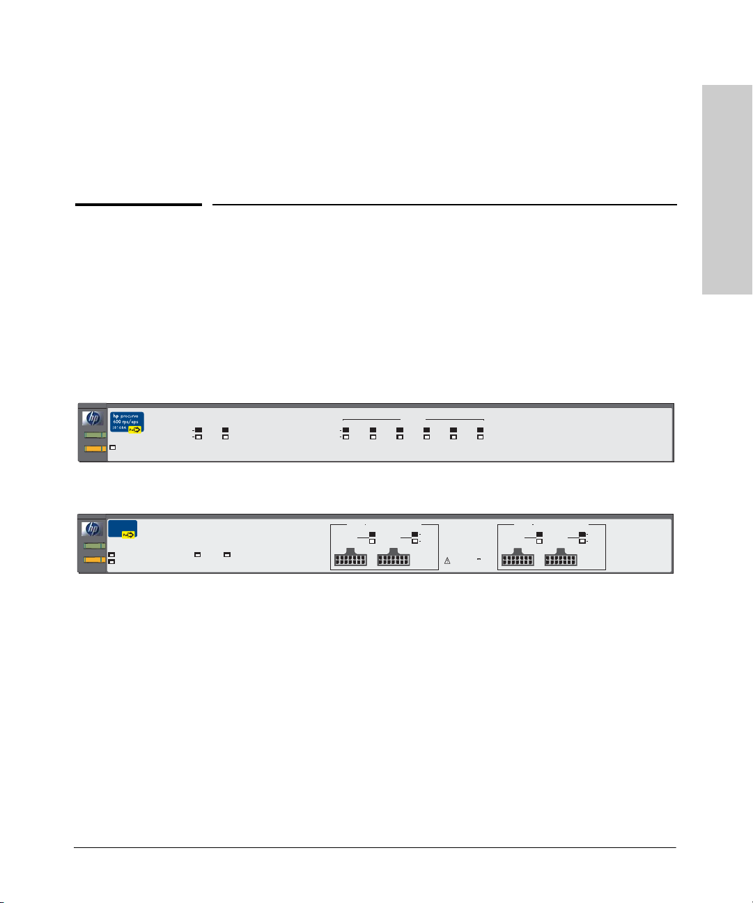
EPS PortStatus
E1
E2
Device Connected
Power
Fault
Power
Fault
Fan/Temp
Status
Fan/TempStatus flash = Temperature too high
Fan/TempStatus + Fault flash = Fan failure
HP ProCurve
610 EPS
J8169A
Internal Power Status
Fan/Temp Status
Fan/TempStatus flash = Temperature too high
Fan/TempStatus + Fault flash = Fan failure
Power Status
EPS Backup Power Ports Status
Out Ready
In Ready
HP ProCurve 600 Redundant and External Power Supply (J8168A)
Device Connected
Power Status
R6 R5
RPS Port Status
R4 R3
R1
R2
HP ProCurve 610 External Power Supply (J8169A)
EPS Ports PairA
EPS A1
(
408 W total for PoE applications
)
Device
A1
A2
Connected
EPS A2 EPS B1
Power
Status
EPS Ports: 50 V
8.3 A max per port pair.
EPS Ports PairB
(
408 W total for PoE applications
B1
EPS B2
)
Device
B2
Connected
Power
Status
Throughout this manual, these units will be abbreviated as the HP 600 RPS/
EPS and HP 610 EPS.
The HP 600 RPS/EPS has six redundant power supply (RPS) ports supporting
backup power to six supported HP ProCurve switches. The HP 600 RPS/EPS
also has two external power supply (EPS) ports that provide PoE power for
up to two HP PoE switches.
The HP 610 EPS has four EPS ports that provide PoE power for up to four HP
PoE switches. The HP 610 EPS also has two backup ports for supporting
backup power to other HP 610 EPS units connected in a group. There are two
supported topologies, a string (daisy-chain) and a ring (closed-loop).
1-1
Page 10

Introducing the HP ProCurve 600/610 External Power Supplies
610 External Power Supplies
Introducing the HP ProCurve 600/
This chapter describes your HP 600 RPS/EPS and HP 610 EPS including:
■ front of the unit (page 1-3)
■ back of the unit (page 1-6)
■ RPS port operation (page 1-8)
■ EPS port operation (page 1-8)
■ backup power port operation (page 1-9)
■ supported switches (page 1-10)
1-2
Page 11
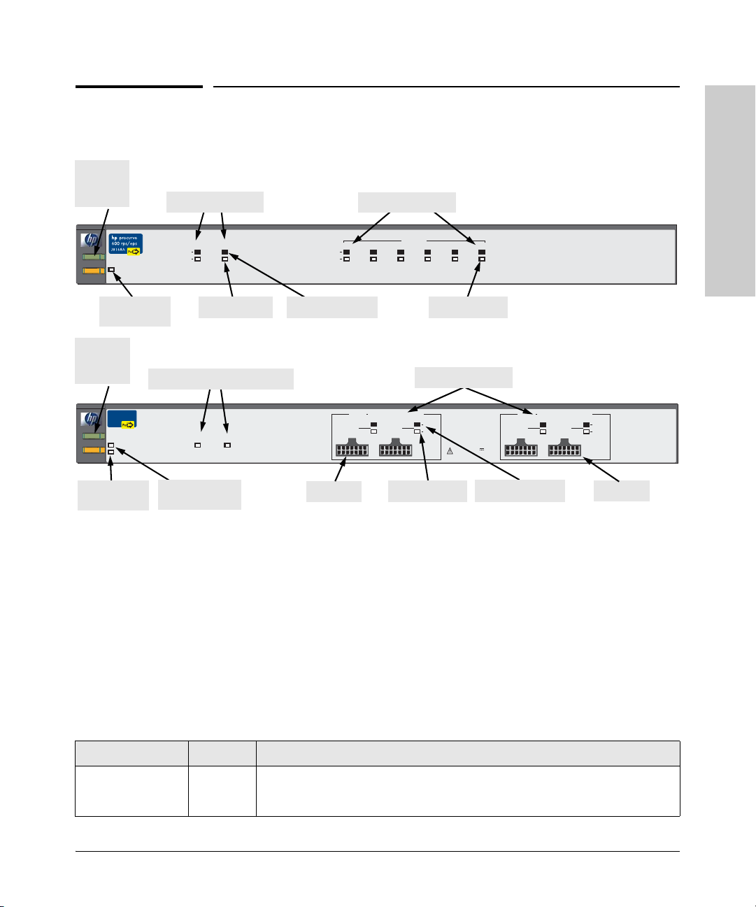
Power
and Fault
LEDs
Front of the Unit
EPS port LEDs
Introducing the HP ProCurve 600/610 External Power Supplies
Front of the Unit
RPS port LEDs
HP 600 RPS/EPS
Introducing the HP ProCurve 600/
610 External Power Supplies
Fan/Temp
Power
Status
Fan/TempStatus flash = Temperature too high
Fault
Fan/TempStatus + Fault flash = Fan failure
Fan/Temp
Status LED
Power
and Fault
LEDs
HP ProCurve
610 EPS
J8169A
Power
Fan/TempStatus flash = Temperature too high
Fault
Fan/TempStatus + Fault flash = Fan failure
Fan/Temp
Status LED
Device Connected
Power Status
EPS Backup Power port LEDs
Internal Power Status
Fan/Temp Status
EPS Backup Power Ports Status
In Ready
Internal Power
Status LED
EPS PortStatus
E1
E2
Power Status
Out Ready
R6 R5
Device Connected
Power Status
Device Connected
EPS Ports PairA
EPS A1
EPS Pair A
RPS Port Status
R4 R3
R1
R2
Power Status
EPS port LEDs
(
408 W total for PoE applications
)
Device
A1
A2
Connected
EPS A2 EPS B1
Power
Status
EPS Ports: 50 V
8.3 A max per port pair.
Power Status
Device Connected
EPS Ports PairB
(
408 W total for PoE applications
B1
EPS B2
HP 610 EPS
)
Device
B2
Connected
Power
Status
EPS Pair B
EPS Ports on the HP 610 EPS
The HP 610 EPS has four external power supply ports. You can connect one
to four HP PoE capable switches to provide PoE power as a primary or backup
source. Power is equally shared between the EPS ports in pair A (that is, port
A1 and A2) and between the EPS ports in pair B (port B1 and B2); one port in
each pair supplies maximum power (408 W) if the other port is not used.
LEDs
Table 1-1. HP 600 RPS/EPS and HP 610 EPS LEDs
LED State Meaning
Power
(green)
On The unit is powered on.
Off The unit is NOT powered on.
1-3
Page 12

Introducing the HP ProCurve 600/610 External Power Supplies
Front of the Unit
Table 1-1. HP 600 RPS/EPS and HP 610 EPS LEDs (Continued)
LED State Meaning
Fault
(orange)
610 External Power Supplies
Introducing the HP ProCurve 600/
Internal Power
Status (green)
(also on back panel
of the HP 610 EPS)
Fan/Temp Status
(green)
Port Status (also on back panel of the HP 600 RPS/EPS)
Device Connected
(green – over-laid
with the port
number)
Power Status
(green)
Off The normal state; indicates that there are no fault conditions on the unit.
Blinking*†A fault has occurred on the unit, one of the ports, or the fan. The Status LED for the
component with the fault will blink simultaneously.
On On briefly after the unit is powered on or reset, at the beginning of unit self test. If
this LED is on for a prolonged time, the unit has encountered a fatal hardware
failure, or has failed its self test. See chapter 3, “Troubleshooting” for more
information.
On The HP 610 EPS unit’s internal power supply is operating normally.
Blinking* The HP 610 EPS unit’s internal power supply has failed and the unit is being
powered by another HP 610 EPS. The unit Fault LED will be blinking simultaneously.
On The cooling fans are operating normally.
Blinking* One of these conditions exists:
• A cooling fan has failed. The unit Fault LED will be blinking simultaneously.
• There is an over temperature condition in the unit. The unit Fault LED is off.
On There is a valid connection to a device. For xl PoE Modules, the EPS Device
Connected LED is only on if the module is receiving power from the 5300 switch
chassis.
Off There is no device connected to the port.
On The unit is supplying power to a connected device.
Off One of these conditions exists:
• There is no connected device.
• A connected RPS device does not require power.
• A connected EPS device has not successfully communicated for EPS power.
Blinking* One of these conditions exists:
• On the HP 600 RPS/EPS, RPS power is not available to the connected device
because a higher priority port is using it.
• When the LED is blinking simultaneously with the Fault LED, there is a fault
condition on the port.
* The blinking behavior is an on/off cycle once every 1.6 seconds, approximately.
†
Specific fault conditions can be viewed by checking switch log files.
1-4
Page 13

Introducing the HP ProCurve 600/610 External Power Supplies
Front of the Unit
Table 1-1. HP 600 RPS/EPS and HP 610 EPS LEDs (Continued)
LED State Meaning
EPS Backup Power Status (on front and back panels of the HP 610 EPS only)
In Ready
(green)
Out Ready
(green)
* The blinking behavior is an on/off cycle once every 1.6 seconds, approximately.
On Backup power is available from another HP 610 EPS in the backup power group.
Off Backup power is not available. One of these conditions exists:
• There is not adequate reserve power in the other units to support this device.
• The backup power cable is not properly connected.
• One or more of the backup power cables are faulty.
On Backup power is available for other HP 610 EPS units in the backup power group.
Off Backup power is not available for other HP 610 EPS units. The unit’s internal power
supply has failed and the unit is being powered by another HP 610 EPS. The unit’s
Internal Power Status and Fault LEDs will be blinking simultaneously.
Introducing the HP ProCurve 600/
610 External Power Supplies
1-5
Page 14
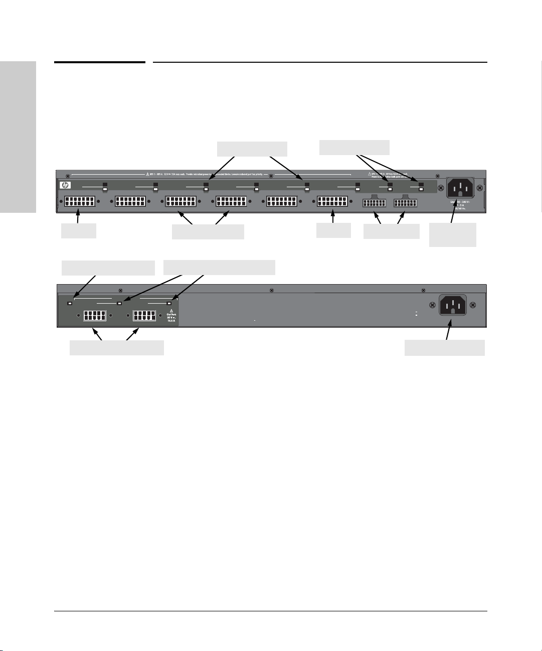
Introducing the HP ProCurve 600/610 External Power Supplies
Back of the Unit
Back of the Unit
Device Connected
RPS 1
610 External Power Supplies
Power Status
Introducing the HP ProCurve 600/
RPS 1
Internal Power Status LED
In
In
Internal
Internal
Power
Power
Status
Status
EPS Backup Power ports
RPS 2
EPS Backup Power Ports
EPS Backup Power Ports
Ready
Ready
RPS port LEDs
EPS port LEDs
HP 600 RPS/EPS
R2
R3R1
RPS 3
R4
RPS 4
RPS ports
R5
RPS 5
RPS 6
R6
RPS 6
E1
EPS 1
EPS ports
EPS Backup Power port LEDs
Ready
Out
Out
Ready
Multiple power sources disconnect both t he AC cord and EPS Bac kup power cables to completely remove power from the unit.
Device
E2
Connected
EPS 2
Power
Status
AC power
connector
HP 610 EPS
Hz
Line: 50/60
240 V~
110
11 6 A
AC power connector
RPS Ports on the HP 600 RPS/EPS
The HP 600 RPS/EPS has six redundant power supply ports. You can connect
up to six HP ProCurve switch units, but backup power can be supplied to only
one unit based on port priority. Port 1 has the highest priority and port 6 the
lowest. A switch connected to port 1 always receives power before any other
port. Likewise, port 2 receives power before ports 3 to 6, port 3 receives power
before ports 4 to 6, and so on down to port 6, which only receives power when
no other port is receiving power.
1-6
EPS Ports on the HP 600 RPS/EPS
The HP 600 RPS/EPS has two external power supply ports. You can connect
one or two HP PoE capable switches to provide PoE power as a primary or
backup source. Power is equally shared between the two EPS ports (204 W
each); one port supplies maximum power (408 W) if the other port is not used.
Page 15

Introducing the HP ProCurve 600/610 External Power Supplies
Back of the Unit
Port Status LEDs
The RPS and EPS port status LEDs on the HP 600 RPS/EPS back panel are a
duplication of those on the front panel. Similarly, the backup power port status
LEDs on the HP 610 EPS back panel are a duplication of those on the front
panel. For a description of these LEDs, see Table 1-1 on page 1-3.
Internal Power Status LED
The Internal Power Status LED on the HP 610 EPS back panel is a duplication
of the one on the front panel. For a description of this LED, see Table 1-1 on
page 1-3.
EPS Backup Power Ports
The HP 610 EPS has two backup power ports that allow up to five EPS units
to be connected together and thereby provide backup power to a failed unit.
However, note that the power load on the remaining active units must be
limited so that there is still enough reserve power to support a failed unit. The
simplest way is to have one unit in the group that has no direct PoE load on
it. Sample topologies are shown at the end of chapter 2 in this book.
Power Connector
Introducing the HP ProCurve 600/
610 External Power Supplies
The HP 600 RPS/EPS and HP 610 EPS do not have a power switch; they are
powered on when connected to an active AC power source. The HP 600 RPS/
EPS automatically adjusts to any voltage between 100--240 volts and either 50
or 60 Hz, and the HP 610 EPS between 110--240 volts and either 50 or 60 Hz.
There are no voltage range settings required.
In addition, the HP 610 EPS may be powered on when receiving power
through a backup power port even when not connected to an active AC power
source.
Caution The power cords supplied for the HP 600 RPS/EPS may be of a lower amperage
rating than those supplied for the HP 610 EPS. For safe operation, only use
the AC power cord that is supplied with the HP 610 EPS.
1-7
Page 16

Introducing the HP ProCurve 600/610 External Power Supplies
RPS Port Operation
610 External Power Supplies
Introducing the HP ProCurve 600/
RPS Port Operation
The HP 600 RPS/EPS can be connected to six switches through RPS cables,
but can provide redundant power to only one switch whose AC power or
internal power supply fails. The unit can provide up to 180 W of power at
+12 VDC to a single switch.
Each RPS port has a priority, with port 1 the highest and port 6 the lowest.
The HP 600 RPS/EPS always provides power to a switch connected to a higher
priority port, if necessary by dropping power to a switch on a lower priority
port. The switching of power from low-priority ports to high-priority ports is
completely automatic and effectively instantaneous.
The HP 600 RPS/EPS is able to detect switches connected to each RPS port
and also the status of their primary AC power supply. The unit supports a hotplug feature where switches can be connected or disconnected to the RPS
ports without causing any disruption either to switch operation or the HP 600
RPS/EPS. Over-current protection on each RPS port prevents any switch from
exceeding the power supply limit of the unit. Any overload condition causes
the HP 600 RPS/EPS to shut down the port.
1-8
EPS Port Operation
The HP 600 RPS/EPS supports two EPS ports and the HP 610 EPS supports
four EPS ports that can provide power to PoE capable switches through EPS
cables. Each external power supply unit can provide PoE power to a switch
as a primary source or as a backup to a switch that has its own internal PoE
power supply.
The EPS ports operate as a pair. The HP 600 RPS/EPS has one pair of EPS
ports that can provide up to 408 W of PoE power at -50 VDC. The HP 610 EPS
has two pairs of EPS ports, each of which can provide up to 408 W of PoE
power at -50 VDC. There are four possible power allocations for each EPS port
pair:
■ Maximum power allocated to the first port and none to the second
■ Maximum power allocated to the second port and none to the first
■ Each port in the pair are allocated half of the maximum power
■ No power allocated to either port in the pair
Page 17

Introducing the HP ProCurve 600/610 External Power Supplies
EPS Backup Power Port Operation
For example, the HP 600 RPS/EPS can allocate 408 W of power to port 1 and
none to port 2, or each port can be allocated 204 W. The HP 610 EPS can
allocate all 408 W of power to port A1 (in pair A) and none to port A2, or each
port can be allocated 204 W.
If power is shared between the two EPS ports, current limits are set to prevent
an over-current condition. An over-current condition causes the port power
to be shut down. Also, EPS power may not be delivered if a connected device
has not successfully communicated for EPS power. Lastly, if the internal EPS
power supply fails, EPS power will be lost unless backup power is provided
from another HP 610 EPS in a backup power group. Try disconnecting, then
reconnecting the EPS cable to restore EPS power. See “Recommended
Connection Topologies” on page 2-16.
EPS Backup Power Port Operation
Up to five HP 610 EPS units can be connected together through EPS backup
power cables, but the EPS backup power ports can provide redundant power
to only one unit whose AC power fails. The active units can provide up to
850 W of power to a single failed HP 610 EPS.
The HP 610 EPS is able to detect other units connected to the backup power
ports and also the status of their primary AC power supply. The HP 610 EPS
supports a hot-plug feature where units can be connected or disconnected to
the backup power ports without causing any disruption to the units in the
backup power group.
Introducing the HP ProCurve 600/
610 External Power Supplies
Note HP recommends connecting the “IN” connector first, then connect the “OUT”
connector. Connecting in this manner ensures there is no voltage on the cable.
1-9
Page 18

Introducing the HP ProCurve 600/610 External Power Supplies
Supported Switches
Supported Switches
Switch HP Product Number EPS/RPS Support
HP ProCurve Switch 2824 J4903A RPS power only
HP ProCurve Switch 2848 J4904A RPS power only
610 External Power Supplies
Introducing the HP ProCurve 600/
HP ProCurve Switch 2626-PWR J8164A Both EPS and RPS power
HP ProCurve Switch 2650-PWR J8165A Both EPS and RPS power
HP ProCurve Switch xl PoE Module J8161A EPS power only
1-10
Page 19

Installing and Connecting the HP 600/610 External Power Supplies
The HP 600 RPS/EPS and HP 610 EPS come with an accessory kit that
includes the brackets for mounting the unit in a standard 19-inch telco rack
or in an equipment cabinet, and rubber feet that can be attached so the unit
can be securely located on a horizontal surface. The brackets are designed to
allow mounting the unit in a variety of locations and orientations.
This chapter shows you how to install the HP 600 RPS/EPS and HP 610 EPS
including:
■ included parts (page 2-2)
■ installation procedures (page 2-3)
■ recommended connection topologies (page 2-16)
2
Installing and Connecting the HP
600/610 External Power Supplies
2-1
Page 20

600/610 External Power Supplies
Installing and Connecting the HP
Installing and Connecting the HP 600/610 External Power Supplies
Included Parts
Included Parts
The HP 600 RPS/EPS and HP 610 EPS have the follo wing components shipped
with them:
■ HP ProCurve 600/610 External Power Supplies Installation and Getting
Started Guide (5990-8800), this manual
■ HP ProCurve PoE Planning and Implementation Guide (5990-8801)
■ Read Me First (5990-8799)
■ Customer Support/Warranty booklet (5990-6019)
■ Accessory kits
(5069-6535) for HP 600 RPS/EPS (5069-5705) for HP 610 EPS
• two mounting brackets
• eight 8-mm M4 screws to attach the
mounting brackets to the unit
• four 5/8-inch number 12-24 screws to
attach the unit to a rack
• four rubber feet
* The mounting brackets differ from the 5069-6535 mounting brackets by being longer to
support the increased depth of the unit.
■ EPS cables; two for the HP 600 RPS/EPS, four for the HP 610 EPS
■ Six RPS cables (HP 600 RPS/EPS only)
■ One EPS backup power cable (HP 610 EPS only)
■ AC power cord, one of the following:
• two mounting brackets*
• eight 8-mm M4 screws to attach the
mounting brackets to the unit
• four 5/8-inch number 12-24 screws to
attach the unit to a rack
• four rubber feet
Japan Power
Cord Warning
2-2
United States/Canada/Mexico
Continental Europe
United Kingdom/Hong Kong/Singapore
Australia/New Zealand
Japan
China
Denmark
Switzerland
HP 610 EPS only:
United States/Canada/Mexico
Japan
8120-5337
8120-5336
8120-5334
8120-5335
8120-5342
8120-8385
8120-5340
8120-5339
8121-0914
8120-5338
Page 21

Installing and Connecting the HP 600/610 External Power Supplies
Installation Procedures
Installation Procedures
Summary
Follow these easy steps to install your HP 600 RPS/EPS or HP 610 EPS. The
rest of this chapter provides details on these steps.
1. Prepare the installation site (page 2-6). Make sure the physical
environment into which you will be installing the unit is properly
prepared, including having the correct cabling ready to connect to the unit
and having an appropriate location for the unit. Please see page 2-4 for
installation precautions.
2. Mount the unit (page 2-6). The unit can be mounted in a 19-inch telco
rack, in an equipment cabinet, or on a horizontal surface.
3. Connect devices to the unit (page 2-9). Using the supplied RPS and
EPS cables, connect the unit to the devices that it will support with
redundant power or PoE power.
4. Connect up to five HP 610 EPS units together to form a backup
power group (page 2-11). The backup power ports can support a single
failed HP 610 EPS connected in a group.
Installing and Connecting the HP
600/610 External Power Supplies
5. Connect power to the unit (page 2-13). Once the unit is mounted,
plug it into a nearby main AC power source.
6. Verify the unit is operating correctly (page 2-14). This is a simple
process of observing that the LEDs on the unit’s front panel indicate
correct operation.
At this point, your unit is fully installed. See the rest of this chapter if you need
more detailed information on any of these installation steps.
2-3
Page 22
600/610 External Power Supplies
Installing and Connecting the HP
Installing and Connecting the HP 600/610 External Power Supplies
Installation Procedures
Installation Precautions:
Follow these precautions when installing your HP 600 RPS/EPS or
HP 610 EPS:
WARNINGS ■ The rack or cabinet should be adequately secured to prevent it
from becoming unstable and/or falling over.
Devices installed in a rack or cabinet should be mounted as low as
possible, with the heaviest devices at the bottom and progressively
lighter devices installed above.
■ Do not use power cord, part number 8120-5337 or 8120-5342, with
the HP 610 EPS. A power cord with a minimum wire gauge of
14 Awg is required to prevent overloading of the power cord. (This
applies to voltages of less than 127 volts.)
■
Cautions ■ Make sure the power source circuits are properly grounded, then use the
power cord supplied with the unit to connect it to the power source.
■ If your installation requires a different power cord than the one supplied
with the unit, be sure to use a power cord displaying the mark of the safety
agency that defines the regulations for power cords in your country. The
mark is your assurance the power cord can be used safely with the unit.
2-4
■ When installing the unit, note that the AC outlet should be near the unit
and should be easily accessible in case the unit must be powered off.
■ Ensure the unit does not overload the power circuits, wiring, and over-
current protection. To determine the possibility of overloading the supply
circuits, add together the ampere ratings of all devices installed on the
same circuit as the unit and compare the total with the rating limit for the
circuit. The maximum ampere ratings are usually printed on devices near
the AC power connectors.
■ Do not install the unit in an environment where the operating ambient
temperature might exceed 55°C (131°F) for the HP 600 RPS/EPS or 50°C
(122°F) for the HP 610 EPS.
■ Make sure the air flow around the sides and back of the unit is not
restricted. If this unit is placed in a fully enclosed rack, make certain the
ambient temperature inside the rack near the unit does not exceed 55°C
(131°F) for the HP 600 RPS/EPS or 50°C (122°F) for the HP 610 EPS.
Page 23

Installing and Connecting the HP 600/610 External Power Supplies
Installation Procedures
■ For safe operation and to prevent equipment damage, DO NOT connect
EPS, RPS, or HP 610 EPS backup power cables to non-supported equipment or in non-supported configurations.
■ If the HP 610 EPS is actively providing backup power to another
HP 610 EPS, disconnect AC power cord before removing backup power
cables. This will reduce possible sparking and equipment damage.
Installing and Connecting the HP
600/610 External Power Supplies
2-5
Page 24

Installing and Connecting the HP 600/610 External Power Supplies
Installation Procedures
1. Prepare the Installation Site
■ Cabling - Only use the EPS cables supplied with the unit for external
power connections to switches. Only use the EPS backup power cables
supplied with the HP 610 EPS to connect to other HP 610 EPS units in the
backup power group. Only use the RPS cables supplied with the
HP 600 RPS/EPS for redundant power connections to switches.
■ Installation Location - Before installing the unit, plan its location and
orientation relative to other devices and equipment:
• In both the front and back of the unit, leave at least 7.6 cm (3 inches)
of space for the EPS and RPS cables, EPS backup power cables, and
the power cord.
• On the sides of the unit, leave at least 7.6 cm (3 inches) for cooling.
2. Mount the Unit
The HP 600 RPS/EPS and HP 610 EPS can be mounted in these ways:
■ in a rack or cabinet
■ on a horizontal surface
600/610 External Power Supplies
Installing and Connecting the HP
Rack or Cabinet Mounting
The HP 600 RPS/EPS and HP 610 EPS are designed to be mounted in any EIAstandard 19-inch telco rack or communication equipment cabinet. The
mounting brackets have multiple mounting holes and can be rotated allowing
for a wide variety of mounting options.
WARNING For safe operation, please read the mounting precautions on
page 2-4, before mounting the unit.
Equipment
Cabinet
Note
2-6
The 12-24 screws supplied with the unit are the correct threading for standard
EIA/TIA open 19-inch racks. If you are installing the unit in an equipment
cabinet such as a server cabinet, use the clips and screws that came with the
cabinet in place of the 12-24 screws that are supplied with the unit.
1. Use a #1 Phillips (cross-head) screwdriver and attach the mounting
brackets to the unit with the included 8-mm M4 screws. The screws must
be tightened sufficiently to provide proper support for the unit in the rack.
Page 25

8 mm
M4 screws
Installing and Connecting the HP 600/610 External Power Supplies
Installation Procedures
Attaching brackets to the HP 600 RPS/EPS
Installing and Connecting the HP
600/610 External Power Supplies
8 mm
M4 screws
Attaching brackets to the HP 610 EPS
2-7
Page 26

Installing and Connecting the HP 600/610 External Power Supplies
Installation Procedures
WARNING For safe reliable installation, only use the screws provided in the
accessory kit to attach the mounting brackets to the unit.
Note Note that the mounting brackets have multiple mounting holes and can be
rotated allowing for a wide variety of mounting options. These include
mounting the unit so that its front face is flush with the face of the rack, or
mounting it in a more balanced position as shown in the illustration above.
2. Hold the unit with attached brackets up to the rack and move it vertically
until rack holes line up with the bracket holes, then insert and tighten the
four number 12-24 screws holding the brackets to the rack.
600/610 External Power Supplies
Installing and Connecting the HP
Horizontal Surface Mounting
Place the unit on a table or other horizontal surface. The unit comes with
rubber feet in the accessory kit that can be used to help keep the unit from
sliding on the surface.
Attach the rubber feet to the four corners on the bottom of the unit within the
embossed angled lines. Use a sturdy surface in an uncluttered area. You may
want to secure the EPS and RPS cables and the unit’s power cord to the table
leg or other part of the surface structure to help prevent tripping over the
cords.
Caution Make sure the air flow is not restricted around the sides and back of the unit.
2-8
Page 27

Installing and Connecting the HP 600/610 External Power Supplies
S
Installation Procedures
3. Connect to Switches
Connect the EPS and RPS cables from the supported network switches to the
appropriate ports on the HP 600 RPS/EPS and HP 610 EPS.
Connecting RPS Ports to Switches
To connect:
Push the RPS cable plug into the d esired
RPS port until the thumb screws engage
with the screw holes in the unit. Tighten
the plug thumb screws to secure the
connection.
When power is on for the HP 600 RPS/
EPS and for the connected switch, the
Device Connected LED should go on to
confirm a powered-on switch is at the
other end of the cable.
If the Device Connected LED does not
go on when the RPS cable is connected
to the port, see Diagnosing with the
LEDs in chapter 3, “Troubleshooting.”
RPS Cable:
• Only use the cables supplied with the unit
• The cable connectors are keyed and can
only be attached in one orientation
R3
3
R4
RPS 4
RP
Installing and Connecting the HP
600/610 External Power Supplies
Note Connect switches to the RPS ports based on their priority, with the highest
priority switch connected to port 1.
To disconnect:
Unscrew the thumb screws on the plug and pull the plug out of the port.
2-9
Page 28

Installing and Connecting the HP 600/610 External Power Supplies
Installation Procedures
Connecting EPS Ports to Switches
To connect:
Push the EPS cable plug into the EPS
port until the tab on the plug clicks into
place. When power is on for the
HP 600 RPS/EPS or HP 610 EPS and for
the connected device, the Device
Connected LED should go on to confirm
a powered-on switch is at the other end
of the cable.
If the Device Connected LED does not
go on when the EPS cable is connected
to the port, see Diagnosing with the
LEDs in chapter 3, “Troubleshooting.”
R6
EPS 1
E1
EPS 2
600/610 External Power Supplies
Installing and Connecting the HP
To disconnect:
Press the small tab on the plug and pull
the plug out of the port.
EPS Cable:
• Only use the cables supplied with the unit
• The cable connectors are keyed and can
only be attached in one orientation
Refer to “EPS Port Operation” on page 1-8 for detailed information and on PoE
power usage, and to “Limitations” on page 2-18 for information on maximum
available PoE power.
2-10
Page 29

Installing and Connecting the HP 600/610 External Power Supplies
d
d
d
d
Installation Procedures
4. HP 610 EPS Only: Connect the EPS Backup Power Ports
Connect the EPS backup power cables to EPS backup power ports on the
HP 610 EPS.
WARNING For safe reliable operation only connect HP 610 EPS backup power
ports to other HP 610 EPS backup power ports. Do not connect to RPS
ports of other devices.
See Connection Topologies specific to the EPS backup power ports for more
information (page 2-21).
Note HP recommends connecting the “IN” connector first, then connect the “OUT”
connector. Connecting in this manner ensures there is no voltage on the cable.
To connect:
1. Attach the end of the backup power cable marked “IN” to the backup
power “In” port on the first unit in the group of HP 610 EPS units. Push
the cable plug into the port until the thumb screws engage with the screw
holes in the unit. Tighten the plug thumb screws to secure the connection.
Installing and Connecting the HP
600/610 External Power Supplies
2. Attach the end of the EPS backup power cable marked “OUT” to the EPS
backup power “Out” port on the next unit in the group.
PS Backup Power Ports
EPS Backup
EPS Backup
Rea
In
Internal
Internal
Power
Power
Status
Status
In
IN
Rea
IN
EPS Power Backup Cable:
• Only use the cables supplied with the unit
PS Backup Power Ports
Ready
Ready
Rea
Out
Out
OUT
Rea
OUT
• The cable connectors are keyed and can
only be attached in one orientation
2-11
Page 30

Installing and Connecting the HP 600/610 External Power Supplies
Installation Procedures
3. If you are connecting up to five units, attach backup power cables in the
same way between the other units to complete the backup power group.
4. (Optional) To form a closed loop or “ring,” connect a backup power cable
from the backup power “In” port on the last unit to the backup power
“Out” port on the first unit. See “EPS Backup Power” on page 2-21 for more
information on the ring topology.
When power is on for each of the HP 610 EPS units in the group, the EPS
Backup Power Port Status LEDs should go on to confirm that these ports are
functioning properly, and backup power is available to other units in the group.
If an EPS Backup Power Port Status LED does not go on when the backup
power cable is connected to the port, see Diagnosing with the LEDs in chapter
3, “Troubleshooting.”
To disconnect:
Unscrew the thumb screws on the plug and pull the plug out of the port.
Refer to “EPS Backup Power Port Operation” on page 1-9 for detailed information and on backup power, and to “EPS Backup Power” on page 2-21 for
information on maximum available backup power.
600/610 External Power Supplies
Installing and Connecting the HP
2-12
Page 31

Installing and Connecting the HP 600/610 External Power Supplies
Installation Procedures
5. Connect to AC Power
Connect the AC power cord supplied with the HP 600 RPS/EPS or HP 610 EPS
to the power connector on the back of the unit, and then into a properly
grounded electrical outlet.
HP 600 RPS/EPS
RPS 5
R5 R6
RPS 6
E1
EPS 1
Device
E2
Connected
EPS 2
Power
Status
Connect the AC power cord to
the power connector
HP 610 EPS
Hz
Line: 50/60
240 V~
110
connect both the AC cord and EPS B ackup power cables to completely remove power from the unit.
11 6 A
Connect the AC power cord to
the power connector
Note The HP 600 RPS/EPS and HP 610 EPS do not have a power switch. They are
powered on when the power cord is connected to the unit and to a power
source. For safety, the power outlet should be located near the unit installation.
The HP 600 RPS/EPS automatically adjusts to any voltage between 100--240
volts and either 50 or 60 Hz, and the HP 610 EPS between 110--240 volts and
either 50 or 60 Hz. There are no voltage range settings required.
Installing and Connecting the HP
600/610 External Power Supplies
If your installation requires a different power cord than the one supplied with
the unit, be sure the cord is adequately sized for the unit’s current requirements. In addition, be sure to use a power cord displaying the mark of the
safety agency that defines the regulations for power cords in your country.
The mark is your assurance that the power cord can be used safely with the
unit.
2-13
Page 32

Installing and Connecting the HP 600/610 External Power Supplies
a
Installation Procedures
6. Verify Correct Operation
When the HP 600 RPS/EPS or HP 610 EPS is mounted in its location and
powered on, you should first verify that it is working properly by checking the
unit’s LEDs.
Check the LEDs on the unit as described below.
600/610 External Power Supplies
Installing and Connecting the HP
Fan/Temp
Power
Status
Fan/TempStatus flash = Temperature too high
Fault
Fan/TempStatus + Fault flash = Fan failure
Power and
Fault LEDs
HP ProCurve
610 EPS
J8169A
Power
Fan/TempStatus flash = Temperature too high
Fault
Fan/TempStatus + Fault flash = Fan failure
Power and
Fault LEDs
Internal Power Status
Fan/Temp Status
RPS port LEDs
R6 R5
RPS Port Status
R4 R3
Device Connected
Power Status
EPS port LEDs
EPS Port Status
E1
E2
Device Connected
Power Status
Fan/Temp Status LED
EPS Ports Pair A
EPS A1
EPS port LEDs
(
408 W total for PoE applications
EPS A2
)
Device
A2A1
Connected
Power
Status
Fan/Temp
Status LED
EPS Backup Power port LEDs
EPS Backup Power Ports Status
Out Ready
In Ready
Internal Power
Status LED
When the unit is powered on, it performs its diagnostic self test. The self test
takes approximately 5 seconds to complete.
HP 600 RPS/EPS
R2
HP 610 EPS
EPS Ports: 50 V
8.3 A max per port p
R1
2-14
LED Behavior:
During the self test:
• Initially, all the unit and port LEDs are on and stay on for most of the
duration of the self test.
• Most of the LEDs go off and then may come on again during phases
of the self test.
When the self test completes successfully:
•The Power, Internal Power Status, and Fan/Temp Status LEDs remain on.
•The Fault LED goes off.
Page 33

Installing and Connecting the HP 600/610 External Power Supplies
Installation Procedures
• The EPS and RPS Port Status LEDs on the HP 600 RPS/EPS and the
EPS Port Status LEDs on the HP 610 EPS go into their normal operational mode:
– If the ports are connected to active devices, the Device Connected
LEDs should be on.
– If the ports are not connected to active devices, the LEDs stay off.
• The EPS Backup Power Port Status LEDs on the front and rear of the
HP 610 EPS go into their normal operational mode:
– If the ports are connected to active HP 610 EPS units and these
units have adequate reserve power to provide backup service, the
LEDs should be on.
– If the ports are not connected to active HP 610 EPS units or these
units do not have adequate reserve power to provide backup
service, the LEDs stay off.
If the LED display is different than what is described above, especially if
the Fault LED stays on for more than 15 seconds or it starts blinking, the
self test has not completed correctly. Refer to chapter 3, “Trouble-
shooting” for diagnostic help.
Installing and Connecting the HP
600/610 External Power Supplies
2-15
Page 34

Installing and Connecting the HP 600/610 External Power Supplies
Recommended Connection Topologies
Recommended Connection Topologies
This section shows you some recommended connection topologies using the
HP 600 RPS/EPS and HP 610 EPS. For more topology information, see the HP
ProCurve web site, http://www.hp.com/go/hpprocurve.
RPS Connections on the HP 600 RPS/EPS
Recommendations
The HP 600 RPS/EPS can provide backup power support for up to six HP
ProCurve switches. In the illustration below, six HP ProCurve Switch 2650PWR units are connected to the RPS ports on an HP 600 RPS/EPS.
HP ProCurve Switch 2650-PWR units
600/610 External Power Supplies
Installing and Connecting the HP
Lowest priority
connected to port 6
Highest priority
connected to port 1
RPS cables
RPS
50 V 16 A
50 V 16 A
50 V 16 A
50 V 16 A
50 V 16 A
50 V 16 A
Device Connected
RPS 1
Power Status
R2
RPS 2
12 V 7.5 A
RPS
12 V 7.5 A
RPS
12 V 7.5 A
RPS
12 V 7.5 A
RPS
12 V 7.5 A
RPS
12 V 7.5 A
R3R1
RPS 3
RPS 4
R5
R4
RPS 5
RPS 6
Line: 50/60 Hz.
100-240 V~ 7.5 A
Line: 50/60 Hz.
100-240 V~ 7.5 A
Line: 50/60 Hz.
100-240 V~ 7.5 A
Line: 50/60 Hz.
100-240 V~ 7.5 A
Line: 50/60 Hz.
100-240 V~ 7.5 A
Line: 50/60 Hz.
100-240 V~ 7.5 A
R6
EPS 1
Device
E1
E2
Connected
EPS 2
Power
Status
HP 600 RPS/EPS
AC power
2-16
Page 35

Installing and Connecting the HP 600/610 External Power Supplies
Recommended Connection Topologies
Limitations
The HP 600 RPS/EPS can supply power to only one connected and failed
switch at a time. In the illustration above, the switch connected to RPS port 1
has the highest priority and the switch connected to RPS port 6 has the lowest
priority. When multiple switches fail, a switch connected to a higher priority
port always receives power before a switch connected to a lower priority port.
Status Indication
The Power Status LEDs on the HP 600 RPS/EPS indicate if a port can provide
power. For example, if six switches are connected to the HP 600 RPS/EPS and
the power to the switch on port 4 fails, the Power Status LED for port 4 turns
on and for ports 5 and 6 it blinks. The Power Status LEDs for ports 1, 2, and 3
remain off. The blinking Power Status LEDs for ports 5 and 6 indicate that
they are lower priority ports and cannot supply power to the connected
switches. The Power Status LED’s are off for ports 1, 2, and 3 because they
have higher priority and if either port requests power, the power will be
removed from port 4 and given to either 1, 2, or 3.
EPS Connections on the HP 600 RPS/EPS
Installing and Connecting the HP
600/610 External Power Supplies
Recommendations
The HP 600 RPS/EPS is designed to provide primary or backup power to up
to two HP PoE switches. In the illustration below, two HP ProCurve Switch
2650-PWR units are being supplied with external PoE power from an
HP 600 RPS/EPS. The switches provide PoE power to Ethernet devices
connected to their ports.
2-17
Page 36

Installing and Connecting the HP 600/610 External Power Supplies
Recommended Connection Topologies
HP ProCurve Switch 2650-PWR units
600/610 External Power Supplies
Installing and Connecting the HP
Device Connected
RPS 1
Power Status
EPS cables
RPS
50 V 16 A
50 V 16 A
R2
RPS 2
12 V 7.5 A
RPS
12 V 7.5 A
R3R1
RPS 3
RPS 4
R5
R4
RPS 5
RPS 6
Line: 50/60 Hz.
100-240 V~ 7.5 A
Line: 50/60 Hz.
100-240 V~ 7.5 A
R6
EPS 1
Device
E1
E2
Connected
EPS 2
Power
Status
HP 600 RPS/EPS
AC Power
Limitations
In the illustration above, the two switches connected to the HP 600 RPS/EPS
are limited to 204 W of power on each EPS port. If a switch tries to draw more
than 204 W of power from the HP 600 RPS/EPS, an over-current condition
occurs and the EPS port shuts down. To supply more than 204 W on one EPS
port, the other port must first be disconnected. The maximum power that can
be provided when only one EPS port is connected to a switch is 408 W.
2-18
Page 37

Installing and Connecting the HP 600/610 External Power Supplies
hp procurve
PoE
xl module
J8161A
xl
module
PoE
Link
Mode
1
2
3
4
56
PoE-Ready 10/100-TX Ports (1-24) all ports are HP Auto-MDIX
13
14
20
19121110
9
8
7
15
21
16
22 23 24
17 18
Std
PoE
PoE
EPS
Status
LED Mode
Mode
Link
hp procurve
PoE
xl module
J8161A
xl
module
PoE
Link
Mode
1
2
3
4
56
PoE-Ready 10/100-TX Ports (1-24) all ports are HP Auto-MDIX
13
14
20
19121110
9
8
7
15
21
16
22 23 24
17 18
Std
PoE
PoE
EPS
Status
LED Mode
Mode
Link
hp procurve
PoE
xl module
J8161A
xl
module
PoE
Link
Mode
1
2
3
4
56
PoE-Ready 10/100-TX Ports (1-24) all ports are HP Auto-MDIX
13
14
20
19121110
9
8
7
15
21
16
22 23 24
17 18
Std
PoE
PoE
EPS
Status
LED Mode
Mode
Link
hp procurve
PoE
xl module
J8161A
xl
module
PoE
Link
Mode
1
2
3
4
56
PoE-Ready 10/100-TX Ports (1-24) all ports are HP Auto-MDIX
13
14
20
19121110
9
8
7
15
21
16
22 23 24
17 18
Std
PoE
PoE
EPS
Status
LED Mode
Mode
Link
Recommended Connection Topologies
EPS Connections on the HP 610 EPS
Recommendations
The HP 610 EPS is designed to provide primary or backup PoE power to up
to four HP PoE devices. It can be used to supply primary PoE power to up to
four HP ProCurve Switch xl PoE modules (J8161A), after they have been
installed in an HP ProCurve Switch 5308xl switch chassis. The HP 610 EPS
can also be used to supply backup PoE power to up to four HP Procurve
Switch 2650-PWR or 2626-PWR devices or a mix of primary and backup PoE
power to both types of switch devices. For more information regarding
connectivity, see the HP ProCurve PoE Planning and Implementation Guide.
Installing and Connecting the HP
600/610 External Power Supplies
EPS cables
Power
Fault
HPProCurve
610 EPS
J8169A
Internal Power Status
Fan/Temp Status
Fan/TempStatusflash = Temperature too high
Fan/TempStatus+ Fault flash = Fan failure
EPS Backup Power Ports Status
In Ready
HP 610 EPS
(
408 W total for PoE applications
EPS Ports PairA
Out Ready
EPS A1
)
Device
A2
A1
Connected
EPS A2 EPS B1
Power
Status
EPS Ports: 50 V
8.3 A max per port pair.
(
408 W total for PoE applications
)
EPS Ports PairB
Device
B1
B2
Connected
EPS B2
Power
Status
HP ProCurve Switch 5308XL
2-19
Page 38

Installing and Connecting the HP 600/610 External Power Supplies
Recommended Connection Topologies
HP ProCurve Switch 2650-PWR units
600/610 External Power Supplies
Installing and Connecting the HP
Power
Fault
EPS cables
HPProCurve
610 EPS
J8169A
Internal Power Status
Fan/Temp Status
Fan/TempStatusflash = Temperature too high
Fan/TempStatus+ Fault flash = Fan failure
50 V 16 A
50 V 16 A
50 V 16 A
50 V 16 A
EPS Backup Power Ports Status
In Ready
RPS
12 V 7.5 A
RPS
12 V 7.5 A
RPS
12 V 7.5 A
RPS
12 V 7.5 A
(
408 W total for PoE applications
EPS Ports PairA
Out Ready
EPS A1
)
Device
A2
A1
Connected
EPS A2 EPS B1
Power
Status
EPS Ports: 50 V
8.3 A max per port pair.
EPS Ports PairB
(
408 W total for PoE applications
B1
Line: 50/60 Hz.
100-240 V~ 7.5 A
Line: 50/60 Hz.
100-240 V~ 7.5 A
Line: 50/60 Hz.
100-240 V~ 7.5 A
Line: 50/60 Hz.
100-240 V~ 7.5 A
EPS B2
)
Device
B2
Connected
Power
Status
AC power
HP 610 EPS
Limitations
EPS ports A1 and A2 share one common internal power supply; ports B1 and
B2 share a second common internal power supply. The maximum power that
can be supplied to each port pair is 408 W. In other words, if both ports in a
pair are connected to PoE switches, then the maximum power that each port
can provide is 204 W; but if only one port in a pair is connected to a PoE switch,
that port can provide up to 408 W.
2-20
In the illustration above, the four switches connected to the HP 610 EPS are
limited to 204 W of power on each EPS port. If a switch tries to draw more
than 204 W of power from the HP 610 EPS, an over-current condition occurs
and the EPS port shuts down. To supply more than 204 W on one EPS port,
the other port in the pair must first be disconnected. The maximum power
that can be provided when only one EPS port in a pair is connected to a switch
is 408 W.
Status Indication
The EPS Port Power Status LEDs on the HP 610 EPS indicate if an EPS port
is providing power to the connected device. For example, if four switches are
connected to the HP 610 EPS and the power to the switch on port A1 fails, the
Power Status LED for port A1 turns off, but for ports A2, B1, and B2 it remains
on.
Page 39

Installing and Connecting the HP 600/610 External Power Supplies
Recommended Connection Topologies
EPS Backup Power
The purpose of the backup power is to provide redundancy to the PoE power
provided by the HP 610 EPS. Redundancy in PoE power can prevent loss of
power to PoE devices in the event of AC power failure or a power supply
failure on a connected HP 610 EPS.
Each HP 610 EPS incorporates a PoE power supply that is connected so it can
provide power to itself or another HP 610 EPS connected by a cable. The back
of the HP 610 EPS has backup power input and output connectors for
connecting multiple units together to back up each other. There are two
supported configurations for connectivity:
■ Daisy chain, sometimes referred to as a string. Used when incorporating
an unloaded unit as the backup unit for any failed unit in the string.
Therefore, this backup unit must be the first unit in the string.
■ Closed loop, sometimes referred to as a ring. This allows for distributing
loads across all units. See Limitations. HP recommends the closed-loop
configuration.
For example, in the closed loop, the first HP 610 EPS uses the output
connector to connect to the second or next HP 610 EPS input connector, and
so forth until the final HP 610 EPS output connector connects to the input
connector of the first HP 610 EPS. This then completes the connectivity and
closes the loop.
Installing and Connecting the HP
600/610 External Power Supplies
The main difference between the closed loop and the daisy chain is in the daisy
chain the output of the final HP 610 EPS does not connect to anything.
2-21
Page 40

Installing and Connecting the HP 600/610 External Power Supplies
Recommended Connection Topologies
EPS Backup Power Ports
First
Last
EPS Backup Power Ports
In
In
Internal
Internal
Power
Power
Status
Status
EPS Backup Power Ports
EPS Backup Power Ports
In
In
Internal
Internal
Power
Power
Status
Status
EPS Backup Power Ports
EPS Backup Power Ports
In
In
Internal
Internal
Power
Power
Status
Status
EPS Backup Power Ports
EPS Backup Power Ports
In
In
Internal
Internal
Power
Power
Status
Status
EPS Backup Power Ports
EPS Backup Power Ports
In
In
Internal
Internal
Power
Power
Status
Status
Ready
Ready
Ready
Ready
Out
Out
Ready
Ready
Ready
Ready
Out
Out
Ready
Ready
Ready
Ready
Out
Out
Ready
Ready
Ready
Ready
Out
Out
Ready
Ready
Ready
Ready
Out
Out
Multiplepower sources disconnectboththe AC cord and EPS Backup power cables to completely remove power from the unit.
Multiplepower sources disconnectboththe AC cord and EPS Backup power cables to completely remove power from the unit.
Multiplepower sources disconnectboththe AC cord and EPS Backup power cables to completely remove power from the unit.
Multiplepower sources disconnectboththe AC cord and EPS Backup power cables to completely remove power from the unit.
Multiplepower sources disconnectboththe AC cord and EPS Backup power cables to completely remove power from the unit.
HP 610 EPS units
connected in a string
Hz
Line: 50/60
240 V~
110
11 6 A
Hz
Line: 50/60
240 V~
110
11 6 A
Hz
Line: 50/60
240 V~
110
11 6 A
Hz
Line: 50/60
240 V~
110
11 6 A
Hz
Line: 50/60
240 V~
110
11 6 A
600/610 External Power Supplies
Installing and Connecting the HP
EPS Backup Power cables
AC power
Note The “First” unit is the one with only the “Out” port connected.
The cable connectors are keyed so they must connect an output to an input.
You cannot connect an input to an input. When HP 610 EPS units are
connected in this manner, this allows the sharing of PoE power from one unit
to the other, down the line, should a failure occur.
2-22
Page 41

Installing and Connecting the HP 600/610 External Power Supplies
Recommended Connection Topologies
HP 610 EPS units
connected in a ring
EPS Backup Power Ports
EPS Backup Power Ports
In
In
Internal
Internal
Power
Power
Status
Status
EPS Backup Power Ports
EPS Backup Power Ports
In
In
Internal
Internal
Power
Power
Status
Status
EPS Backup Power Ports
EPS Backup Power Ports
In
In
Internal
Internal
Power
Power
Status
Status
EPS Backup Power Ports
EPS Backup Power Ports
In
In
Internal
Internal
Power
Power
Status
Status
EPS Backup Power Ports
EPS Backup Power Ports
In
In
Internal
Internal
Power
Power
Status
Status
Ready
Ready
Ready
Ready
Out
Out
Ready
Ready
Ready
Ready
Out
Out
Ready
Ready
Ready
Ready
Out
Out
Ready
Ready
Ready
Ready
Out
Out
Ready
Ready
Ready
Ready
Out
Out
Multiplepower sources disconnectboththe AC cord and EPS Backup power cables to completely remove power from the unit.
Multiplepower sources disconnectboththe AC cord and EPS Backup power cables to completely remove power from the unit.
Multiplepower sources disconnectboththe AC cord and EPS Backup power cables to completely remove power from the unit.
Multiplepower sources disconnectboththe AC cord and EPS Backup power cables to completely remove power from the unit.
Multiplepower sources disconnectboththe AC cord and EPS Backup power cables to completely remove power from the unit.
Hz
Line: 50/60
240 V~
110
11 6 A
Hz
Line: 50/60
240 V~
110
11 6 A
Hz
Line: 50/60
240 V~
110
11 6 A
Installing and Connecting the HP
Hz
Line: 50/60
240 V~
110
11 6 A
Hz
Line: 50/60
240 V~
110
11 6 A
600/610 External Power Supplies
EPS Backup Power cables
The illustration above shows an example of five HP 610 EPS units connected
in a closed-loop configuration.
Recommendations
The recommended installation is to connect all of the HP 610 EPS units into
one ring. The more units there are in a ring, the more efficient the redundancy.
For example, with three units in a ring the maximum total load for redundancy
is 2/3 of the maximum available power. However with five units in the ring,
the maximum total load is 4/5 of the maximum available power.
Limitations (Calculating required number of HP 610 EPS units)
The total PoE load on all HP 610 EPS units must be less than the total power
available from N-1 of the power supplies, where N is the number of connected
units. The load on each HP 610 EPS must be no greater than the maximum
allowable for a single unit (850 W).
AC power
2-23
Page 42

600/610 External Power Supplies
Installing and Connecting the HP
Installing and Connecting the HP 600/610 External Power Supplies
Recommended Connection Topologies
There is a need for some way to ensure this requirement is met. There are two
ways to do this:
■ Sum up all the loads and divide by 850 W (round up to next whole number),
this gives you the required number of HP 610 EPS units. Now for backup
redundancy add one more HP 610 EPS unit.
Or
■ Do not put any load on ONE of the HP610 EPS units, (in a string this must
be the “First” unit). See the illustration and note on page 2-22.
For example, you have 150 phones at 8 W each and 10 wireless access points
at 12 W each, this totals 1320 W. Now you must divide 1320 W by 850 W (the
power of one HP 610 EPS) to get the number of units you will need to support
the 1320 W. 1320 W divided by 850 W equals 1.55. Therefore, you need two
HP 610 EPS units to support these devices. You must round up to the next
whole number. For full backup redundancy, you will need to add one more
HP 610 EPS for a total of three units.
The loads do not have to be distributed equally, for example:
■ With four HP 610 EPS units in a ring, redundancy is achieved if unit A has
a full single load, and B, C, and D each have 2/3 of a maximum single load.
■ With four HP 610 EPS units in a ring, redundancy is achieved if A, B, C,
and D each have 3/4 of a maximum single load.
■ With five HP 610 EPS units, redundancy is achieved if four units have the
maximum single load, and one unit has zero load.
■ With five HP 610 EPS units, redundancy is achieved if all five units have
4/5 of a maximum single load.
2-24
All the preceding examples require a closed-loop configuration. If any unit in
the chain fails, all units then share their power to support the failed unit.
Page 43

Failed unit supported by
other units in the group
Installing and Connecting the HP 600/610 External Power Supplies
Recommended Connection Topologies
HP 610 EPS units
connected in a ring
EPS Backup Power Ports
EPS Backup Power Ports
Ready
Ready
In
In
Internal
Internal
Power
Power
Status
Status
EPS Backup Power Ports
EPS Backup Power Ports
Ready
Ready
In
In
Internal
Internal
Power
Power
Status
Status
EPS Backup Power Ports
EPS Backup Power Ports
Ready
Ready
In
In
Internal
Internal
Power
Power
Status
Status
EPS Backup Power Ports
EPS Backup Power Ports
Ready
Ready
In
In
Internal
Internal
Power
Power
Status
Status
EPS Backup Power Ports
EPS Backup Power Ports
Ready
Ready
In
In
Internal
Internal
Power
Power
Status
Status
Ready
Ready
Out
Out
Ready
Ready
Out
Out
Ready
Ready
Out
Out
Ready
Ready
Out
Out
Ready
Ready
Out
Out
Multiplepower sources disconnectboththe AC cord and EPS Backup power cables to completely remove power from the unit.
Multiplepower sources disconnectboththe AC cord and EPS Backup power cables to completely remove power from the unit.
Multiplepower sources disconnectboththe AC cord and EPS Backup power cables to completely remove power from the unit.
Multiplepower sources disconnectboththe AC cord and EPS Backup power cables to completely remove power from the unit.
Multiplepower sources disconnectboththe AC cord and EPS Backup power cables to completely remove power from the unit.
Hz
Line: 50/60
240 V~
110
11 6 A
Hz
Line: 50/60
240 V~
110
11 6 A
Hz
Line: 50/60
240 V~
110
11 6 A
Installing and Connecting the HP
Hz
Line: 50/60
240 V~
110
11 6 A
Hz
Line: 50/60
240 V~
110
11 6 A
600/610 External Power Supplies
EPS Backup Power cables
AC power
Status Indication
The backup power connector status LEDs indicate if an HP 610 EPS is
connected to another HP 610 EPS unit, and the other unit is powered on. On
the front of the HP 610 EPS there are two LEDs indicating the status of the
backup power. One LED is labeled “IN,” and when it is ON it indicates the
backup power input is connected to another live HP 610 EPS backup power
output.
The other LED is labeled “Out,” and when it is on it indicates the backup power
output is connected to another HP 610 EPS backup power input.
These LEDs do not indicate whether power is flowing or not. They only
indicate that the connections are good and that power is available. In a normal
operating ring, all of these LEDs should be on. These LEDs are also duplicated
on the HP 610 EPS rear panel.
Fault Conditions
A faulty backup power cable connection is indicated by an LED that goes off
for two connected HP 610 EPS units. One unit will have its “In” LED off, and
the other unit will have its “Out” LED off. These LEDs are replicated on both
the front and back of the HP 610 EPS.
2-25
Page 44

Installing and Connecting the HP 600/610 External Power Supplies
Recommended Connection Topologies
A power supply failure is indicated by:
■ Blinking Internal Power Supply LED on the front and back of the
HP 610 EPS
■ EPS Backup Power “Out” LED off on the failed unit
■ EPS Backup Power “In” LED off on the next unit in line
■ Blinking Fault LED on switch connected to the failed HP 610 EPS
Replacement Procedures
In the event of a failure, this is the recommended procedure to follow to
replace a failed unit.
1. Identify the failed unit and schedule downtime for the attached PoE
devices.
2. Reduce the PoE load of the failed unit.
3. Remove the EPS cables.
4. Remove the backup power cables. Additionally, remove the cable
attached to the “Out” port of the previous unit.
5. Remove the AC power.
600/610 External Power Supplies
Installing and Connecting the HP
6. Remove the failed unit.
7. Install a new unit, then reverse this procedure.
Remember, it is the preferred procedure for connecting backup power cables
to attach the “IN” cable end before attaching the “OUT” cable end.
UPS Support
The HP 600 RPS/EPS and HP 610 EPS may be used in configurations where
an Uninterruptible Power Supply (UPS) is desired. See Appendix A, “Specifi-
cations,” for the power requirements of the HP 600 RPS/EPS and HP 610 EPS
for use in determining your UPS requirements.
2-26
Page 45

Troubleshooting
This chapter describes how to troubleshoot your HP 600 RPS/EPS and
HP 610 EPS.
This chapter describes the following:
■ basic troubleshooting tips (page 3-1)
■ diagnosing with the LEDs (page 3-2)
■ diagnostic tests (page 3-5)
■ HP customer support services (page 3-6)
Basic Troubleshooting Tips
Most problems are caused by the following situations. Check for these items
first when starting your troubleshooting:
■ Faulty or loose cables. Look for loose or obviously faulty connections.
If the cables appear to be OK, make sure the connections are secure. If
that does not correct the problem, try a different cable.
■ Connection topologies. It is important to make sure you have a valid
connection topology. The HP 600 RPS/EPS can support two HP PoE
devices on its EPS ports, but with limited power output. Up to six HP
ProCurve switches can be connected to RPS ports, but only one can be
supplied power based on port priority. The HP 610 EPS can support four
HP PoE devices on its EPS ports, but with limited power output on each
port pair. The HP 610 EPS units can be connected together to supply
backup power to other units. However, the power load on the units must
be limited so that there is still enough power to support a failed unit.
Sample topologies are shown at the end of chapter 2 in this book.
■ Power limitations. Be sure to understand the power limitations of the
HP 600 RPS/EPS and HP 610 EPS when connecting switches. An overload
condition on a port causes the port to be shut down.
3
Troubleshooting
Note Use caution when power cycling the HP 600 RPS/EPS or HP 610 EPS as this
may affect devices receiving operating power from the unit.
3-1
Page 46

Troubleshooting
Diagnosing with the LEDs
Diagnosing with the LEDs
Table 3-1 shows LED patterns on the HP 600 RPS/EPS and HP 610 EPS that
indicate problem conditions.
1. Check in the table for the LED pattern that you see on your unit.
2. Refer to the corresponding diagnostic tip on the next few pages.
Table 3-1. LED Error Indicators
LED Pattern Indicating Problems
Internal
Power Fault
Off with
power cord
plugged in
On Prolonged On * * * * *
On Blinking
On Blinking
On Off * Blinking
On Blinking
On Off * * * On with cable
***** *
Power Status
†
†
†
*** * *
* Blinking
*** *Blinking
Troubleshooting
On Off * * * Off with cable
On Off * * * On with cable
On Off * * Off with cable
On Blinking
†
Blinking
†
Fan/Temp
Status
* On with cable
EPS Backup
(HP 610 EPS
†
† ††
connected
connected
Device
Power
only)
** *
** *
Connected
connected
connected
connected
**
**
Power
Status
†
†
Blinking
(RPS port only)
Off
††
Off
(EPS port only)
Diagnostic
Tip s
➊
➋
➌
➍
➎
➏
➐
➑
➒
➓
* This LED is not important for the diagnosis.
†
The blinking behavior is an on/off cycle once every 1.6 seconds, approximately,
††
Check the log file of the connected switch for a message on the fault.
3-2
Page 47

Diagnostic Tips:
Tip Problem Solution
Diagnosing with the LEDs
Troubleshooting
➊
➋
➌
➍
The unit is not
plugged into an
active AC power
source, or the
unit’s power
supply may have
failed.
A hardware
failure has
occurred. All the
LEDs will stay on
indefinitely.
The unit has
experienced a
failure.
One or more of
the unit cooling
fans may have
failed.
1. Verify the power cord is plugged into an active power source and to the unit. Make
sure these connections are snug.
2. Try power cycling the unit by unplugging and plugging the power cord back in.
3. If the Power LED is still not on, verify that the AC power source works by plugging
another device into the outlet. Or try plugging the unit into a different outlet or try a
different power cord.
If the power source and power cord are OK and this condition persists, the unit’s power
supply may have failed. Call your HP-authorized LAN dealer, or use the electronic support
services from HP to get assistance. See the Customer Support/Warranty booklet for more
information.
Try power cycling the unit. If the fault indication reoccurs, the unit may have failed. Call
your HP-authorized LAN dealer, or use the electronic support services from HP to get
assistance. See the Customer Support/Warranty booklet for more information.
Try resetting the unit by power cycling the unit.
If necessary to resolve the problem, contact your HP-authorized LAN dealer, or use the
electronic support services from HP to get assistance. See the Customer Support/
Warranty booklet for more information.
Try disconnecting power from the unit and waiting a few moments. Then reconnect the
power to the unit and check the LEDs again. If the error indication reoccurs, one or more
of the fans has failed. The unit has four fans and may continue to operate under this
condition if the ambient temperature does not exceed normal room temperature, but for
best operation, the unit should be replaced. Contact your HP-authorized LAN dealer, or
use the electronic support services from HP to get assistance. See the Customer Support/
Warranty booklet for more information.
Troubleshooting
➎
➏
➐
There is an over
temperature
condition in the
unit.
The port for
which the LED is
blinking has
experienced a
failure.
RPS power is not
available to the
connected
device.
Check the log file of the connected switch for more detailed information. Make sure the
air flow around the sides and back of the unit is not restricted. Also check to see that no
hot exhaust air from another device is blowing on the unit. If this unit is in a fully enclosed
rack, make certain that the ambient temperature inside the rack near the unit does not
exceed 55°C (131°F) for the HP 600 RPS/EPS or 50°C (122°F) for the HP 610 EPS.
An over-current condition may have been caused by a connected device. Unplug the
cable connected to the port, then plug it back in. If the condition returns, carefully power
cycle the unit (be careful that other devices connected to the unit will not be adversely
affected). If the fault indication reoccurs, the unit port may have failed. Call your HPauthorized LAN dealer, or use the electronic support services from HP to get assistance.
See the Customer Support/Warranty booklet for more information.
A higher priority RPS port is using RPS power from the HP 600 RPS/EPS. The LED blinks
even if the connected device does not require RPS power at this time. The blinking LED
is indicating that there is no RPS power available to that device should it be required.
Higher priority ports will get RPS power if it is needed, so their Power Status LED remains
off. The highest priority device should be connected to RPS port 1 to ensure that it receives
power if it is needed.
3-3
Page 48

Troubleshooting
Diagnosing with the LEDs
Tip Problem Solution
➑
➒
➓
The connection
is not working
properly.
EPS power is not
available.
EPS Backup
power is not
available.
Internal power
supply has failed.
Try the following procedures:
• For the indicated port, verify that both ends of the cabling, at the unit and the connected
device, are connected properly.
• Verify the connected device and unit are both powered on and operating correctly.
• If the other procedures don’t resolve the problem, try using a different port or a different
cable.
A PoE switch is connected to the port, but is not requesting EPS power.
Check the log file of the connected switch for more detailed information. Possible causes
are an over-current condition on the port; a failure to successfully communicate with a
connected device; a failed EPS power supply in the unit. Try disconnecting, then
reconnecting the EPS cable. Wait three to four seconds for the device to successfully
communicate for EPS power. Also try another EPS cable. If this fails to restore EPS power,
call your HP-authorized LAN dealer, or use the electronic support services from HP to get
assistance. See the Customer Support/Warranty booklet for more information.
Verify the backup power cable is connected to each HP 610 EPS in the group. If the backup
power cable is properly connected, and the other units are powered on without internal
power fault conditions, then the backup power cable may be faulty.
The HP 610 EPS unit’s internal power supply has failed and the unit is being powered by
another HP 610 EPS in the backup power group.
1. Verify the AC power cord is plugged into an active power source and to the unit. Make
sure these connections are snug.
2. If the Internal Power Status LED does not go on, verify the AC power source works by
plugging another device into the outlet. Or try plugging the unit into a different outlet
or try a different AC power cord.
If the AC power source and power cord are OK and this condition persists, the unit’s power
supply may have failed. Call your HP-authorized LAN dealer, or use the electronic support
services from HP to get assistance. See the Customer Support/Warranty booklet for more
information.
Troubleshooting
3-4
Page 49

Troubleshooting
Diagnostic Tests
Diagnostic Tests
Testing the Unit by Resetting It
If you believe the HP 600 RPS/EPS or HP 610 EPS is not operating correctly,
you can reset the unit to test its circuitry and operating code. To reset a unit,
unplug and plug in the power cord (power-cycling). For HP 610 EPS units, the
backup power cables must be disconnected first.
Note Use caution when power cycling the unit as this may affect devices receiving
operating power from the unit.
Power-cycling the HP 600 RPS/EPS or HP 610 EPS causes the unit to perform
its power-on self test, which normally resolves any temporary operational
problems.
Checking the Unit’s LEDs
The self test passes if the Fault LED on the front of the HP 600 RPS/EPS or
HP 610 EPS goes off after approximately 5 seconds. If this LED stays on longer
than 15 seconds or begins blinking, there may be a problem with the unit.
See “Diagnosing with the LEDs” on page 3-2 for information on interpreting
the LED patterns.
Testing Cabling
EPS or RPS cables that fail to provide a link or provide an unreliable link
between the unit and the connected device may be faulty. To verify your cable,
try using it to connect to a device that is known to operate correctly or try
using a different port. If the problem persists, replace it with another cable.
EPS backup power cables that fail to provide power to other HP 610 EPS units
in a backup power group may be faulty. To verify a backup power cable, try
using it to connect between HP 610 EPS units that are known to operate
correctly. If the problem persists, replace it with another cable.
3-5
Troubleshooting
Page 50

Troubleshooting
HP Customer Support Services
HP Customer Support Services
If you are still having trouble with your HP 600 RPS/EPS or HP 610 EPS,
Hewlett-Packard offers support 24 hours a day, seven days a week through a
number of automated electronic services. See the Customer Support/Warranty
booklet that came with your HP 600 RPS/EPS or HP 610 EPS for information
on how to use these services to get technical support. The HP ProCurve web
site, http://www.hp.com/go/hpprocurve also provides up-to-date support
information under “product support.”
Additionally, your HP-authorized network reseller can provide you with assistance, both with services that they offer and with services offered by HP.
Troubleshooting
3-6
Page 51

Specifications
Physical
Width: 44.3 cm (17.4 in) 44.3 cm (17.4 in)
Depth: 32.6 cm (12.8 in) 48.3 cm (19.0 in)
Height: 4.4 cm (1.7 in) 4.4 cm (1.7 in)
Weight: 5.3 kg (11.68 lbs) 7.4 kg (16.31 lbs)
Electrical
The unit automatically adjusts to any voltage between the stated values and
either 50 or 60 Hz.
A
HP 600 RPS/EPS HP 610 EPS
HP 600 RPS/EPS HP 610 EPS
AC voltage: 100 – 240 volts 110 – 240 volts
Maximum current: 9 – 5 A 11 – 6 A
Frequency range: 50/60 Hz 50/60 Hz
Power consumption: 821 watts 1130 watts
Environmental
HP 600 RPS/EPS HP 610 EPS
Operating Temperature: 0°C to 55°C (32°F to 131°F) 0°C to 50°C (32°F to 122°F)
Non-Operating Temperature -40°C to 70°C (-40°F to 158°F) -40°C to 70°C (-40°F to 158°F)
Operating Relative humidity:
(non-condensing)
Non-Operating Relative
humidity: (non-condensing)
Maximum altitude: 4.6 Km (15,000 ft) 4.6 Km (15,000 ft)
15% to 95% at 40°C (104°F) 15% to 95% at 40°C (104°F)
90% maximum at 65°C (149°F) 90% maximum at 65°C (149°F)
Specifications
A-1
Page 52

Specifications
Acoustic
HP 600 RPS/EPS
Geraeuschemission LwA=59.2 dB am fiktiven Arbeitsplatz nach DIN 45635
T. 19
Noise Emission LwA=59.2 dB at virtual workspace according to DIN 45635
T. 19
HP 610 EPS
Geraeuschemission LwA=58 dB am fiktiven Arbeitsplatz nach DIN 45635 T.19
Noise Emission LwA=58 dB at virtual workspace according to DIN 45635 T.19
Connectors
■ EPS Ports: 2x7-pin Micro-Fit 3 mm
■ RPS Ports: 2x7-pin Mini-Fit 4.2 mm
■ Backup Power Ports: 2x5-pin Mini-Fit Jr. 4.2 mm
Safety
Complies with:
■ EN60950 / IEC 60950
■ CSA 22.2 No. 60950
■ UL 60950
Specifications
EMC Compliance (Class A)
Complies with:
■ FCC Part 15.107
■ ICES-003 (Canada)
■ VCCI
■ CISPR-22
Immunity
■ CISPR-24
A-2
Page 53

B
Connectors and Cables
This appendix includes connector and cable information for cables that
should be used with the HP 600 RPS/EPS and HP 610 EPS, including minimum
pin-out information and specifications for EPS, RPS, and backup power
cables.
HP 600 RPS/EPS Ports
The EPS and RPS ports on the unit’s back panel accept only the EPS and RPS
cables included with the HP 600 RPS/EPS. These cables are described on the
following pages.
Caution Use only the EPS and RPS cables supplied with the unit. Use of other cables
may result in damage to the equipment.
HP 610 EPS Ports
Connectors and Cables
The EPS ports on the unit’s front panel and the EPS backup power ports on
the unit’s back panel accept only the EPS and backup power cables included
with the HP 610 EPS. These cables are described on the following pages.
Caution Use only the EPS and backup power cables supplied with the unit. Use of other
cables may result in damage to the equipment.
B-1
Page 54

Connectors and Cables
Connector Pin-Outs
Connector Pin-Outs
The HP 600 RPS/EPS includes two EPS ports and six RPS ports. The
HP 610 EPS includes four EPS ports and two backup power ports. The EPS
ports must be connected to HP PoE switches using the provided EPS cables.
The RPS ports must be connected to HP ProCurve switches using the provided
Connectors and Cables
RPS cables. The backup power ports must be connected to other HP 610 EPS
units using the provided backup power cables.
EPS Cable for HP PoE Switch Connections
The EPS cables supplied with the HP 600 RPS/EPS and HP 610 EPS must be
used for all EPS connections.
Connector Diagram
14
7
8
1
Pin Assignments
Pins Signal Name Signal Description
1 nINT A signal from the unit to the attached device that indicates an
interrupt is requested.
2 SDA The control signal from the attached switch.
3 CGND A ground connection to the shell of the chassis and the cable
to restrict EMI within the cable assembly.
4,7,8,14 50RET The positive side of the isolated 50V supply.
5,6,12,13 -50V The negative side of the isolated 50V supply.
8 DCOM Provides a ground return and reference for the control and
9 SCL The clock signal generated by the attached device.
10 nPRSNT Indicates to the unit that an attached device is present.
status signals from the attached device.
B-2
Page 55

Connectors and Cables
Connector Pin-Outs
RPS Cable for HP ProCurve Switch Connections
The RPS cables supplied with the HP 600 RPS/EPS must be used for all RPS
connections.
Connector Diagram
14
7
Pin Assignments
Pins Signal Name Signal Description
1 GND 12V power return
2- Not used
3,4,5,6 12V 12V power from the HP 600 RPS/EPS
7 GND 12V power return
8 GND 12V power return
8
1
Connectors and Cables
9- Not used
10 RPS_Present RPS present signal from HP 600 RPS/EPS
11 Status_1 Provides the condition of the HP 600 RPS/EPS to the attached
12 Status_2 Provides the condition of the HP 600 RPS/EPS to the attached
13 Power_Good Power Good signal to the HP 600 RPS/EPS
14 GND 12V power return
switch
switch
B-3
Page 56

Connectors and Cables
Connector Pin-Outs
EPS Backup Power Cable for HP 610 EPS Connections
The EPS backup power cable supplied with the HP 610 EPS must be used for
all connections to other HP 610 EPS units in the backup power group (string
or ring).
Connector Diagram
10
Connectors and Cables
5
6
1
Pin Assignments (10-pin Connector)
Pins Signal Name Signal Description
1,2,6 -50V The negative side of the isolated 50V supply.
3 GND A ground connection to the shell of the chassis and the cable
4,8,9 50RET The positive side of the isolated 50V supply.
7 LED Indicates connection to backup power
5,10 — These pins are used to key IN and OUT.
to restrict EMI within the cable assembly.
B-4
Page 57

Safety and EMC Regulatory Statements
Safety Information
Documentation reference symbol. If the product is marked with this
!
symbol, refer to the product documentation to get more information
about the product.
C
Safety and EMC Regulatory
WARNING A WARNING in the manual denotes a hazard that can cause injury
or death.
Caution A Caution in the manual denotes a hazard that can damage equip-
ment.
Do not proceed beyond a WARNING or Caution notice until you
have understood the hazardous conditions and have taken appropriate steps.
Grounding
This product is a safety class I compliant product and has a protective earthing
terminal. There must be an uninterruptible safety earth ground from the main
power source to the product's power cord or supplied power cord set.
Whenever it is likely that the protection has been impaired, disconnect the
power cord until the ground has been restored..
For LAN cable grounding:
■ If your LAN covers an area served by more than one power distribu-
tion system, be sure their safety grounds are securely interconnected.
■ LAN cables may occasionally be subject to hazardous transient volt-
ages (such as lightning or disturbances in the electrical utilities power
grid). Handle exposed metal components of the network with caution.
Servicing
There are no user-serviceable parts inside this product. Any servicing, adjustment, maintenance, or repair must be performed only by service-trained
personnel.
Statements
This product does not have a power switch; it is powered on when the power
cord is plugged in.
C-1
Page 58

Safety and EMC Regulatory Statements
Informations concernant la sécurité
Informations concernant la sécurité
Symbole de référence à la documentation. Si le produit est marqué de
!
ce symbole, reportez-vous à la documentation du produit afin d'obtenir
des informations plus détaillées.
Safety and EMC Regulatory
WARNING Dans la documentation, un WARNING indique un danger susceptible
Caution Un texte de mise en garde intitulé Caution indique un danger suscep-
Cet appareil est un produit de classe I et possède une borne de mise à la terre. La source
Statements
d'alimentation principale doit être munie d'une prise de terre de sécurité installée aux
bornes du câblage d'entrée, sur le cordon d'alimentation ou le cordon de raccordement
fourni avec le produit. Lorsque cette protection semble avoir été endommagée,
débrancher le cordon d'alimentation jusqu'à ce que la mise à la terre ait été réparée.
Mise à la terre du câble de réseau local:
■ si votre réseau local s'étend sur une zone desservie par plus d'un système de
distribution de puissance, assurez-vous que les prises de terre de sécurité
soient convenablement interconnectées.
■ Les câbles de réseaux locaux peuvent occasionnellement être soumis à des
surtensions transitoires dangereuses (telles que la foudre ou des perturbations dans le réseau d'alimentation public). Manipulez les composants
métalliques du réseau avec précautions.
Aucune pièce contenue à l'intérieur de ce produit ne peut être réparée par l'utilisateur.
Tout dépannage, réglage, entretien ou réparation devra être confié exclusivement à un
personnel qualifié.
d'entraîner des dommages corporels ou la mort.
tible de causer des dommages à l'équipement.
Ne continuez pas au-delà d'une rubrique WARNING ou Caution avant
d'avoir bien compris les conditions présentant un danger et pris les
mesures appropriées.
C-2
Cet appareil ne comporte pas de commutateur principal ; la mise sous tension est
effectuée par branchement du cordon d'alimentation.
Page 59

Hinweise zur Sicherheit
Symbol für Dokumentationsverweis. Wenn das Produkt mit diesem
!
Symbol markiert ist, schlagen Sie bitte in der Produktdokumentation
nach, um mehr Informationen über das Produkt zu erhalten.
Safety and EMC Regulatory Statements
Hinweise zur Sicherheit
WARNING Eine WARNING in der Dokumentation symbolisiert eine Gefahr, die
Verletzungen oder sogar Todesfälle verursachen kann.
Caution Caution in der Dokumentation symbolisiert eine Gefahr, die dis Gerät
beschädigen kann.
Fahren Sie nach dem Hinweis WARNING oder Caution erst fort,
nachdem Sie den Gefahrenzustand verstanden und die entsprechenden Maßnahmen ergriffen haben.
Dies ist ein Gerät der Sicherheitsklasse I und verfügt über einen schützenden Erdungsterminal. Der Betrieb des Geräts erfordert eine ununterbrochene Sicherheitserdung
von der Hauptstromquelle zu den Geräteingabeterminals, den Netzkabeln oder dem
mit Strom belieferten Netzkabelsatz voraus. Sobald Grund zur Annahme besteht, daß
der Schutz beeinträchtigt worden ist, das Netzkabel aus der Wandsteckdose herausziehen, bis die Erdung wiederhergestellt ist.
Für LAN-Kabelerdung:
■ Wenn Ihr LAN ein Gebiet umfaßt, das von mehr als einem Stromverteilungs-
system beliefert wird, müssen Sie sich vergewissern, daß die
Sicherheitserdungen fest untereinander verbunden sind.
■ LAN-Kabel können gelegentlich gefährlichen Übergangsspannungen aus-
gesetzt werden (beispielsweise durch Blitz oder Störungen in dem
Starkstromnetz des Elektrizitätswerks). Bei der Handhabung exponierter
Metallbestandteile des Netzwerkes Vorsicht walten lassen.
Dieses Gerät enthält innen keine durch den Benutzer zu wartenden Teile. Wartungs-,
Anpassungs-, Instandhaltungs- oder Reparaturarbeiten dürfen nur von geschultem
Bedienungspersonal durchgeführt werden.
Safety and EMC Regulatory
Statements
Dieses Gerät hat keinen Netzschalter; es wird beim Anschließen des Netzkabels
eingeschaltet.
C-3
Page 60

Safety and EMC Regulatory Statements
Considerazioni sulla sicurezza
Considerazioni sulla sicurezza
Simbolo di riferimento alla documentazione. Se il prodotto è contras-
!
segnato da questo simbolo, fare riferimento alla documentazione sul
prodotto per ulteriori informazioni su di esso.
Safety and EMC Regulatory
WARNING La dicitura WARNING denota un pericolo che può causare lesioni o
Caution La dicitura Caution denota un pericolo che può danneggiare le
Questo prodotto è omologato nella classe di sicurezza I ed ha un terminale protettivo
Statements
di collegamento a terra. Dev'essere installato un collegamento a terra di sicurezza, non
interrompibile che vada dalla fonte d'alimentazione principale ai terminali d'entrata,
al cavo d'alimentazione oppure al set cavo d'alimentazione fornito con il prodotto.
Ogniqualvolta vi sia probabilità di danneggiamento della protezione, disinserite il cavo
d'alimentazione fino a quando il collegaento a terra non sia stato ripristinato.
Per la messa a terra dei cavi LAN:
■ se la vostra LAN copre un'area servita da più di un sistema di distribuzione
elettrica, accertatevi che i collegamenti a terra di sicurezza siano ben collegati
fra loro;
■ i cavi LAN possono occasionalmente andare soggetti a pericolose tensioni
transitorie (ad esempio, provocate da lampi o disturbi nella griglia d'alimentazione della società elettrica); siate cauti nel toccare parti esposte in metallo
della rete.
Nessun componente di questo prodotto può essere riparato dall'utente. Qualsiasi
lavoro di riparazione, messa a punto, manutenzione o assistenza va effettuato esclusivamente da personale specializzato.
morte.
attrezzature.
Non procedere oltre un avviso di WARNING o di Caution prima di
aver compreso le condizioni di rischio e aver provveduto alle misure
del caso.
C-4
Questo apparato non possiede un commutatore principale; si mette scotto tensione
all'inserirsi il cavo d'alimentazione.
Page 61

Safety and EMC Regulatory Statements
Consideraciones sobre seguridad
Consideraciones sobre seguridad
Símbolo de referencia a la documentación. Si el producto va
!
marcado con este símbolo, consultar la documentación del
producto a fin de obtener mayor información sobre el producto.
WARNING Una WARNING en la documentación señala un riesgo que podría
resultar en lesiones o la muerte.
Caution Una Caution en la documentación señala un riesgo que podría
resultar en averías al equipo.
No proseguir después de un símbolo de WARNING o Caution hasta
no haber entendido las condiciones peligrosas y haber tomado las
medidas apropiadas.
Este aparato se enmarca dentro de la clase I de seguridad y se encuentra protegido por
una borna de puesta a tierra. Es preciso que exista una puesta a tierra continua desde
la toma de alimentación eléctrica hasta las bornas de los cables de entrada del aparato,
el cable de alimentación o el juego de cable de alimentación suministrado. Si existe la
probabilidad de que la protección a tierra haya sufrido desperfectos, desenchufar el
cable de alimentación hasta haberse subsanado el problema.
Puesta a tierra del cable de la red local (LAN):
■ Si la LAN abarca un área cuyo suministro eléctrico proviene de más de una
red de distribución de electricidad, cerciorarse de que las puestas a tierra
estén conectadas entre sí de modo seguro.
■ Es posible que los cables de la LAN se vean sometidos de vez en cuando a
voltajes momentáneos que entrañen peligro (rayos o alteraciones en la red
de energía eléctrica). Manejar con precaución los componentes de metal de
la LAN que estén al descubierto.
Este aparato no contiene pieza alguna susceptible de reparación por parte del usuario.
Todas las reparaciones, ajustes o servicio de mantenimiento debe realizarlos solamente el técnico.
Safety and EMC Regulatory
Statements
Este producto no tiene interruptor de potencia; se activa cuando se enchufa el cable
de alimentación.
C-5
Page 62

Safety and EMC Regulatory
Safety and EMC Regulatory Statements
Safety Information (Japan)
Safety Information (Japan)
Statements
C-6
Page 63

Safety and EMC Regulatory Statements
Safety Information (China)
Safety Information (China)
Safety and EMC Regulatory
Statements
C-7
Page 64

Safety and EMC Regulatory Statements
EMC Regulatory Statements
Statements
EMC Regulatory Statements
U.S.A.
FCC Class A
This equipment has been tested and found to comply with the limits for a Class
A digital device, pursuant to Part 15 of the FCC Rules. These limits are
designed to provide reasonable protection against interference when the
equipment is operated in a commercial environment. This equipment generates, uses, and can radiate radio frequency energy and, if not installed and
used in accordance with the instruction manual, may cause interference to
radio communications. Operation of this equipment in a residential area may
cause interference in which case the user will be required to correct the
interference at his own expense.
Canada
Safety and EMC Regulatory
This product complies with Class A Canadian EMC requirements.
Australia/New Zealand
This product complies with Australia/New Zealand EMC Class A
requirements.
Japan
VCCI Class A
C-8
Page 65

Korea
Taiwan
Safety and EMC Regulatory Statements
EMC Regulatory Statements
Safety and EMC Regulatory
Statements
C-9
Page 66

Safety and EMC Regulatory
Safety and EMC Regulatory Statements
EMC Regulatory Statements
Statements
EU Declaration of Conformity
DECLARATION OF CONFORMITY
according to ISO/IEC Guide 22 and EN45014
Manufacturer's Name: Hewlett-Packard Company
Manufacturer's Address: 8000 Foothills Blvd.
Roseville, CA 95747-5502
U.S.A.
declares that the product:
Product Name: HP ProCurve 600 RPS/EPS,
Model Number: J8168A
Regulatory Model Number: RSVLC-0303
conforms to the following Product Specifications:
Safety: EN60950 (2000) / IEC 950 (1999)
EMC: EN 55022 (1998) / CISPR-22 (1997) Class A
EN55024 (1998) / CISPR-24 (1997)
EN 61000-3-2 (2000) / IEC 61000-3-2 (2000) Harmonics
EN 61000-3-3 (1995) / IEC 61000-3-3 (1994) Flicker
Supplementary Information:
The product herewith complies with the requirements of the Low Voltage Directive
73/23/EEC and the EMC Directive 89/336/EEC and carries the CE mark.
Tested with Hewlett-Packard Co. products only.
Roseville, October 31, 2003
C-10
Mike Avery,
Regulatory Engineering Manager
European Contact: Your local Hewlett-Packard Sales and Service Office or Hewlett-Packard GmbH,
Department TRE, Herrenberger Strasse 140, D-71034 Böblingen (FAX:+49-7031-14-3143).
Page 67

DECLARATION OF CONFORMITY
according to ISO/IEC Guide 22 and EN45014
Manufacturer's Name: Hewlett-Packard Company
Manufacturer's Address: 8000 Foothills Blvd.
Roseville, CA 95747-5502
U.S.A.
declares that the product:
Product Name: HP ProCurve 610 EPS
Model Number: J8169A
Regulatory Model Numbers: RSVLC-0403
conforms to the following Product Specifications:
Safety: EN60950 (2000) / IEC 950 (1999)
EMC: EN 55022 (1998) / CISPR-22 (1997) Class A
EN55024 (2001) +A2(2003) / CISPR-24 (1997) + A1, A2
EN 61000-3-2 +A14(2000) / IEC 61000-3-2 (2000) Harmonics
EN 61000-3-3 +A1(2001) / IEC 61000-3-3 (1994) Flicker
Supplementary Information:
The product herewith complies with the requirements of the Low Voltage Directive 73/23/EEC
and the EMC Directive 89/336/EEC and carries the CE mark.
Tested with Hewlett-Packard Co. products only.
Roseville, July 1, 2004
Mike Avery,
Regulatory Engineering Manager
European Contact: Your local Hewlett-Packard Sales and Service Office or Hewlett-Packard GmbH, Department
TRE, Herrenberger Strasse 140, D-71034 Böblingen (FAX:+49-7031-14-3143).
Safety and EMC Regulatory Statements
EMC Regulatory Statements
Safety and EMC Regulatory
Statements
C-11
Page 68

— This page is intentionally unused. —
Page 69

Index
B
back of unit … 1-6
backup power ports … 1-7
EPS ports … 1-3, 1-6
EPS/RPS ports … 1-6
power connector … 1-7
RPS ports … 1-6
backup power cable
unit-to-unit connection … B-4
backup power ports
location on unit … 1-7
basic troubleshooting tips … 3-1
blinking LEDs
error indications … 3-2
C
cabinet
mounting the unit in … 2-6
cables
connecting cables to the unit ports … 2-9
EPS connector pin-outs … B-2
required types … 2-6
requirements … 2-6
testing … 3-5
cables, backup power … B-4
unit-to-unit connection … B-4
cables, EPS … B-2
pin-outs … B-2
cables, EPS connector pin-outs … B-2
cables, RPS … B-3
unit-to-switch connection … B-3
cabling … 2-6
connecting the unit to a power source … 2-13
connector specifications … A-2
diagnostic tests … 3-5
checking the LEDs … 3-5
testing cabling … 3-5
testing the unit only … 3-5
E
electrical specifications, unit … A-1
EMC regulatory statements … C-8
emmissions specifications, unit … A-2
environmental specifications, unit … A-1
EPS cable
pin-outs … B-2
unit-to-device connection … B-2
EPS connections
sample topology … 2-17, 2-19
EPS ports
location on unit … 1-3, 1-6
operation description … 1-3, 1-6
F
Fan Status LED … 1-4
Fault LED … 1-4
behavior during self test … 2-14
behaviors … 1-4
blinking definition … 1-4–1-5
showing error conditions … 3-2
front of unit
LEDs … 1-3
H
horizontal surface
mounting unit on … 2-8
Index
D
description … 1-6
back of unit … 1-6
LEDs … 1-3
unit … 1-1
I
included parts … 2-2
Index – 1
Page 70

Index
installation
cable requirements … 2-6
connecting the unit to a power source … 2-13
horizontal surface mounting … 2-8
location considerations … 2-6
precautions … 2-4
rack or cabinet mounting … 2-6
site preparation … 2-6
summary of steps … 2-3
Internal Power Status LED … 1-4
L
LEDs
behavior during self test … 2-14
blinking definition … 1-4–1-5
checking during troubleshooting … 3-5
descriptions of … 1-3
EPS backup power port … 1-5
error indications … 3-2
Fan Status … 1-4
Fault … 1-4
behavior during self test … 2-14
showing error conditions … 3-2
Internal Power Status … 1-4
location on unit … 1-3
port description … 1-4
Power … 1-3
behavior during self test … 2-14
Self Test
behavior during self test … 2-14
location for the unit, considerations … 2-6
M
mounting the unit
in a rack or cabinet … 2-6
on a horizontal surface … 2-8
N
network devices
connecting to the unit … 2-9
P
parts, included with the unit … 2-2
physical specifications, unit … A-1
pin-outs
EPS cables … B-2
port LEDs
description … 1-4
EPS backup power port … 1-5
location on unit … 1-3
normal operation … 2-15
ports
connecting to … 2-9
connections … 2-9
location on unit … 1-6
RPS, location on unit … 1-6
standards compliance … A-2
power connector … 1-7
Power LED … 1-3
behavior during self test … 2-14
behaviors … 1-3
power source
connecting the unit to … 2-13
precautions
mounting the unit … 2-4
power requirements … 2-4
preparing the installation site … 2-6
R
rack
mounting the unit in … 2-6
regulatory statements … C-8
resetting the unit
troubleshooting procedure … 3-5
ring … 1-1, 2-12, 2-21
RPS cable
unit-to-switch connection … B-3
RPS connections
sample topology … 2-16
RPS ports
location on unit … 1-6
operation description … 1-6
S
safety and regulatory statements … C-1
safety specifications … A-2
self test
Fault LED behavior … 2-14
LED behavior during … 2-14
Power LED behavior … 2-14
2 – Index
Page 71

Self Test LED
behavior during self test … 2-14
specifications
connectors … A-2
electrical … A-1
emmissions … A-2
environmental … A-1
physical … A-1
safety … A-2
string … 1-1, 2-21
summary
of unit installation … 2-3
T
testing
cabling … 3-5
checking the LEDs … 3-5
diagnostic tests … 3-5
unit operation … 3-5
tips for troubleshooting … 3-1
topologies
effects of improper topology … 3-1
samples of … 2-16
troubleshooting … 3-1
basic tips … 3-1
checking the LEDs … 3-5
common problems … 3-1
diagnostic tests … 3-5
effects of improper topology … 3-1
testing the cables … 3-5
testing the unit … 3-5
Index
U
unit
connecting to a power source … 2-13
electrical specifications … A-1
emmissions specifications … A-2
environmental specifications … A-1
included parts … 2-2
mounting in a rack or cabinet … 2-6
mounting on horizontal surface … 2-8
physical specifications … A-1
unit operation
verifying after installation … 2-14
Index – 3
Page 72

— This page is intentionally unused. —
Page 73

Page 74

Technical information in this document
is subject to change without notice.
©Copyright 2001, 2004
Hewlett-Packard Development Company, L.P.
Reproduction, adaptation, or translation
without prior written permission is prohibited
except as allowed under the copyright laws.
Printed in Taiwan
August 2004
Manual Part Number
5990-8800
*5990-8800*
 Loading...