

Page 1
Hewlett-Packard Company
3404 East Harmony Road
Fort Collins, Colorado 80528
Read Before Installing
HP A7789A Fire GL™-UX Graphics Card And Software
System Prerequisites
Your HP workstation must meet the following prerequisites to support the Fire GL-UX graphics
option:
1. Hardware requirements - The A7789A Fire GL-UX card is supported only on hp j6000 and HP
PA-RISCworkstations with the PA-8700 or later processors. At this time, the only supported models are the HP c3650, c3700, j6000 and j6700 Workstations. (HP has not tested other host systems
and does not provide technical support for configurations other than these.)
2. O.S. requirements - The prerequisite OS software must be installed before the Fire GL-UX card
will function as a console device. If the workstation was ordered with the Fire GL-UX card integrated at the factory and HP-UX ignited, the prerequisite software should already be installed.
OS requirements for HP-UX 11.0: On Media:
* General Release Patch Bundle, Nov. 1999 (ACE) 11.0 (Core) Install/Update
* Hardware Enablement Patch Bundle, Mar. 2002 or later 11.0 Support Plus (Mar. 2002)
OS requirements for HP-UX 11i:
* Hardware Enablement Patch Bundle 11i, Mar. 2002 or later 11i Support Plus (Mar. 2002)
You can confirm that you have the necessary O.S. revision and appropriate patch bundles by executing the following commands:
$/usr/sbin/swlist -l bundle | grep ACE (for General Release patches)
Pub. No. A7789-90001
A778 9- 90001
Page 2
$/usr/sbin/swlist -l bundle | grep HWE (for Hardware Enablement patches)
The output should contain information similar to this:
XSWGR1100... General Release Patches, November 1999 (ACE) or
HWE1100... Hardware Enablement Patches for HP-UX 11.00, March 2002 (HWE)
If you do not see lines like this in the output, you should install the appropriate patch bundles
(November 1999 or later ACE and March 2002 or later HWE) before attempting to install the Fire
GL-UX software.
Multi-display configurations - The j6000 and j6700 Workstationscanbeconfiguredtorunmultiple
Fire GL-UX cards in a multi-display environment. At this time, HP does not support the Single Logical Screen functionality with the Fire GL-UX card. You cannot use multiple Fire GL-UX cards in the
c3650 or c3700 Workstations. You also cannot use the Fire GL-UX card concurrently with any other
type of graphics card.
Monitor Support
An HP-supported, full multimode color monitor is required for the Fire GL-UX card.
The following list of monitors, plus all other monitors that HP supports in the future, are supported
with the Fire GL-UX card
NOTE The Fire GL-UX card does not support all timings and resolutions that each display
device will accept. Use the HP System Administration Manager (SAM) utility to select
alternative settings.
See your workstation Owner's Guide for information on using the /opt/graphics/common/bin/
setmon command to produce a list of supported timings and screen resolutions for your workstation.
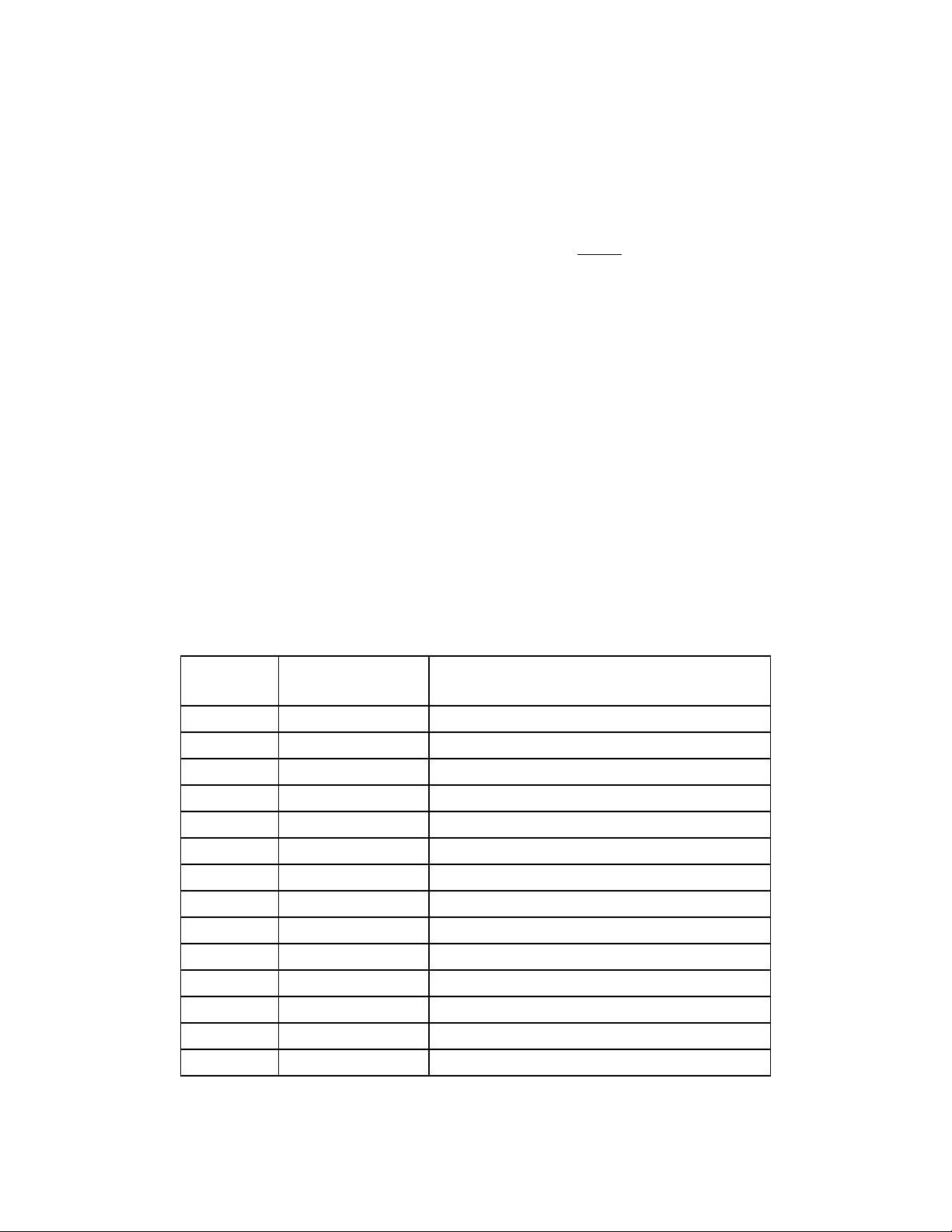
Table 0-1. Fire GL-UX Supported Monitors
Product
Name
P920 D8912W 19-inch color CRT monitor
P910 D8910W 19-inch color CRT monitor
P1130 P4819W 21-inch color CRT monitor
P1120 D8915W 21-inch color CRT monitor
P1110 D2847W 21-inch color CRT monitor
L1820 P4829W 18-inch color LCD flat panel (quartz gray bezel)
L1820 P4829X 18-inch color LCD flat panel (dark gray bezel)
L1810 D5069W 18-inch color LCD flat panel
Product Number Description
A4490A 17-inch color CRT monitor
A4575A 19-inch color CRT monitor
A4576A 21-inch color CRT monitor
A7217A 24-inch color CRT monitor
A1295A 24-inch color CRT monitor
L1800 D5065W 18-inch color LCD flat panel
Page 3

Software Installation Instructions
NOTE The Fire GL-UX Software CD-ROM must be installed prior to using the workstation
when a Fire GL-UX graphics card is installed. Basic drivers for the Fire GL-UX are
included in the Hardware Enablement Bundle (March 2002) and on factory-ignited
workstations. These drivers are supported only for installing the full drivers from the
Fire GL-UX Software CD-ROM. If you are upgrading a workstation that already has a
video card, the Fire GL-UX Software CD-ROM must be installed prior to installing the
Fire GL-UX graphics card.
1. Insert the Fire GL-UX Software CD-ROM (HP Part No. A7789-91001) into your CD-ROM Drive.
2. As root, mount the CD to a directory. For example:
$mount /dev/dsk/c0t0d0 <directory_name>
3. Change directories (cd) to the <directory_name>
4. Execute the “install” script by typing: #./install
This script is included on the CD and contains the appropriate swinstall command and options to
install the software.
5. Your Fire GL-UX software is now ready for use
NOTE For Ignite-UX: The March 2002 (or later) release of Ignite-UX must be used on an
ignite server to boot target workstations having a Fire GL-UX console. All of the
prerequisite OS software and all patches on the Fire GL-UX Software CD-ROM must
be ignited on the target workstation in order to generate a functioning and supported
configuration.
Making Software And Device-specific Changes
For important information on re-configuring an existing graphics card (for example, creating the
proper device files), refer to your workstation Owner's Guide, Technical Reference or the Graphics
Administration Guide which is found on the http://www.hp.com/go/workstationsupport web page.
Removing/Replacing Cards
NOTE Please read your workstation documentation for important system configuration
information.
CAUTION Graphics boards are susceptible to electrostatic shock. When handling your
graphics board, always wear a properly grounded wrist strap and handle the
board carefully. Always unplug the AC power cord from the workstation before
opening the cabinet and performing any installation inside the workstation
Page 4

j6700/j6000 Graphics Cards
Your j-Class Workstation’s PCI (Peripheral Connect Interface) assembly cage has three 64-bit, 4x,
3.3v, 66 MHz card slots, providing I/O expansion capabilities. See Figure 0-1.
Use the Primary Graphics Slot for the highest performance graphics card. Use the Secondary
Graphics Slot for the second graphics card and the remaining slot for any additional supported card.
Figure 0-1 j6700 PCI Card Slot Numbering
Primary Graphics Card Slot
Secondary Graphics Card Slot
NOTE: You will need a T-15 Torx driver or flathead screwdriver to remove the I/O slot bulkhead
screws.
Here are the steps required to remove a graphics card from your j6700 or j6000 computer.
1. Power down the system, and unplug the power cord from the electrical outlet.
2. Open the side panel of the system unit. See your workstation’s User’s Guide for detailed instruc-
Page 5

tions. Follow the instructions below to install cards in the j6000 PCI Cage Assembly.
1
- Lift PCI handle to remove cage from workstation
1. Slide PCI retainer back
2
2. Lift off cage
2
PCI CARD
RETAINER
1
- Insert I/O card in PCI slot as shown
3
- Insert bulkhead screw
Bulkhead
screw
3. Slide the card into the appropriate slot (see #3 above), ensuring that you align Bulkhead Pin(s),
Board Connector(s) and Board Guide(s). Make sure cards are fully seated in their connectors
before replacing the PCI Cage Assembly.
4. Plug the AC power cord into the workstation and power on the workstation.
5. Refer to your workstation documentation for instructions on using the HP-UX System Administration Manager (SAM) utility to verify your graphics configuration
CAUTION The j-Class workstations supply about 75 Watts of power to the PCI slots. Do not insert
cards that together draw more than 75 Watts,ordamage to the workstation may result.
Please look at the specifications that come with your individual cards for power
requirements. Note that each j-Class PCI slot can provide up to 25 watts.
c3650 and c3700 I/O Cards
Your HP c3650 and c3700 computer’s PCI assembly has six slots. Slots 1 through 4 are full-size PCI
Page 6

slots. Slots 5 and 6 are half-size slots. See below for a brief description of slot capabilities.
Figure 0-2 c37xx PCI Card Slot Numbering and Capabilities
Use this slot for your
Fire GL-UX card
To ensure optimum graphics performance, you should always use slot 2 (SL2) as your primary graphics card slot.
If you connect your monitor to a different graphics card slot, you will need to change the graphics path
for that monitor. Note that the six I/O slots as seen from the back of the computer are labeled from top
to bottom starting with one. See below.
Figure 0-3 c3650/c3700 I/O Slot Numbering
I/O Slot 1
I/O Slot 6
You will need a T-15 Torx driver or flathead screwdriver to remove the I/O slot bulkhead screws.
Here are the steps required for remove an I/O card from the system unit.
1. Power off the system, and unplug the system unit power cord from the electrical outlet. Note that
when you press the system power switch, the system automatically performs a shutdown -q.
2. Open the side panel of the system unit. See your User’s Guide for access instructions. Pull evenly
in the direction of the arrow on both PULL tabs of the card retainer to remove it. See below.
Page 7

Figure 0-4 Removing the I/O Card Retainer
I/O Card
I/O Card Retainer
3. Locate the card you want to remove and, using the T-15 Torx driver, remove the I/O card’s
bulkhead screw as shown below:.
Figure 0-5 Removing the I/O Card
I/O Card
Bulkhead
Screw
I/O Card
Bulkhead
4. Pull evenly on the outside edges of the I/O card to remove it.
To install a card into your system unit, follow these steps.
Air Divider
I/O Card Being Removed
1. Locate the appropriate slot for the I/O card that is to be installed.
2. Insert the card into the slot you have chosen with the bulkhead appropriately positioned. See
above. The non-bulkhead end of the card should be placed in the card guide. Press firmly and
evenly on the card until it is seated in the connector. Screw the T-15 Torx screw into the card’s
bulkhead (using 6 inch-pounds of torque) to secure the card.
3. Replace the card retainer by placing the bottom retainer hook in the slot on the air divider and
the clips on the PULL tabs into their slots on the chassis wall.
4. Close the left side panel of the system unit by following the procedure in the User’s Guide. Also
refer to your workstation documentation for instructions on using the HP-UX System Administration Manager (SAM) utility to verify your graphics configuration
Page 8

HP Hardware Warranty
This HP accessory is covered by a limited hardware warranty for a period of one year from the date of
purchase by the original end-user. The type of service provided is return to an HP or repair-authorized reseller service-center.At Hewlett-Packard’s discretion, a defective accessory will be repaired or
replaced by a new unit, either of the same type or of an equivalent model.
If this accessory is purchased and used together with an HP workstation, it will be covered by the
warranty of this computer or workstation, under the same conditions of service and duration. Please
refer to the warranty statement provided with your HP workstation for warranty limitations, customer responsibilities, and other terms and conditions.
FOR CONSUMER TRANSACTIONS IN AUSTRALIA AND NEW ZEALAND: The warranty terms
contained in this statement, except to the extent lawfully permitted, do not exclude, restrict or modify
and are in addition to the mandatory statutory rights applicable to the sale of this product to you.
Software Support
If you encounter problems with displayedimageswhenusingthirdpartyapplicationsoftware, contact
the application software vendor, not Hewlett-Packard, to report problems and/or obtain fixes.
Regulatory Information
NOTE: This graphics card is a Class A device. Systems will perform at FCC Class A /CISPR 22/
EN55022 Class A / VCCI Class A levels when this device is integrated.
Federal Communications Commission Radio Frequency Interference Statement (for USA only)
This equipment has been tested and found to comply with the limits for a Class A digital device, pursuant to Part 15 of the FCC Rules and the Canadian Department of Communications. These limits
are designed to provide reasonable protection against harmful interference when the equipment is
operated in a commercial installation. This equipment generates, uses, and can radiate radio frequency energy and, if not installed and used in accordance with the instructions, may cause harmful
interference to radio communications. Operation of this equipment in a residential area is likely to
cause harmful interference in which case the user will be required to correct the interference at this
own expense.
Hewlett-Packard’s system certification tests were conducted with HP supported peripheral devices
and HP-shielded cables. Changes or modifications no expressly approved by Hewlett-Packard could
void the user’s authority to operate the equipment.
Notice For Canada
This Class A digital apparatus meets all requirements of the Canadian Interference-Causing
Equipment Regulations.
Cet appareil numérique de la Class A respecte toutes les exigences du Règlement sur le matériel
brouilleur du Canada.
Page 9

Notice For Japan (Class A)
Declaration of Conformity
according to ISO/IEC Guide 22 and EN 45014
Manufacturer: Hewlett-Packard Company
Declares that the:
Product Name: Fire GL-UX Graphics Board
Model Number: A7789A
Product Options: All
3404 East Harmony Rd.
Fort Collins, CO 80528
USA
conforms to the following specifications:
Safety EN 60950: 1992+A1+A2+A3+A4+A11
UL 1950/CSA 22.2 No. 950
AS/NS 3260
EMC CISPR 22: 1993+A1+A2 /EN 55022: 1998 Class A
EN 50024:1998 / EN 61000-4-2
EN 50024:1998 / EN61000-4-3
EN 50024:1998 / EN 61000-4-4
EN 50024:1998 / EN 61000-4-5
EN 50024:1998 / EN 61000-4-6
EN 50024:1998 / EN61000-4-11.
AS/NS 3548:1995, Class A
U.S. FCC Part 15, Class A
Japan VCCI Class A
and is certified by:
EMV Testhaus GmbH - DAR accredited Nr: TTI-P-G 101/95-20
Australia/New Zealand AS/NZS 3548:1995
Fort Collins CCQD HTC
Supplementary information:
The product herewith complies with the requirements of the following Directives and carries the CE marking
accordingly:
- the EMC directive 89/336/EEC and 92/31/EEC and 93/68/EEC
- the Low Voltage Directive 73/23/EEC and 93/68/EEC
This product was tested in a typical Hewlett-Packard workstation configuration.
Original signed by Douglas K. Howell, TCD Regulatory Manager, Fort Collins, CO, USA
For Compliance Information ONLY, contact:
European Contact: Your local Hewlett-Packard Sales and Service Office or Hewlett-Packard GmbH,
Department Standards Europe, Herrenberger Strasse 130, D-71034 Boeblingen (FAX: +49-7031-14-3143)
Americas Contact: Hewlett-Packard, TCD Regulatory Mgr.,3404 E. Harmony Road, Fort Collins, CO 80528,
U.S.A.(FAX: (970) 898-4556
 Loading...