

T-13/4 (5 mm) Precision Optical
Performance AlInGaP LED
Lamps
Technical Data
Features
• Well Defined Spatial
Radiation Patterns
• Viewing Angles: 6°, 15°,
23°, 30°
• High Luminous Output
• Colors:
590 nm Amber
605 nm Orange
615 nm Reddish-Orange
626 nm Red
• High Operating
Temperature:
T
J
LED
= +130°C
• Superior Resistance to
Moisture
• Four Package Options:
With or Without Flange Base;
With or Without Lead Stand-
Offs
Benefits
• Viewing Angles Match
Traffic Management Sign
Requirements
• Colors Meet Automotive and
Pedestrian Signal
Specifications
• Superior Performance in
Outdoor Environments
• Suitable for Autoinsertion
onto PC Boards
Applications
• Traffic Management:
Traffic Signals
Pedestrian Signals
Work Zone Warning Lights
Variable Message Signs
• Commercial Outdoor
Advertising:
Signs
Marquees
• Automotive:
Exterior and Interior Lights
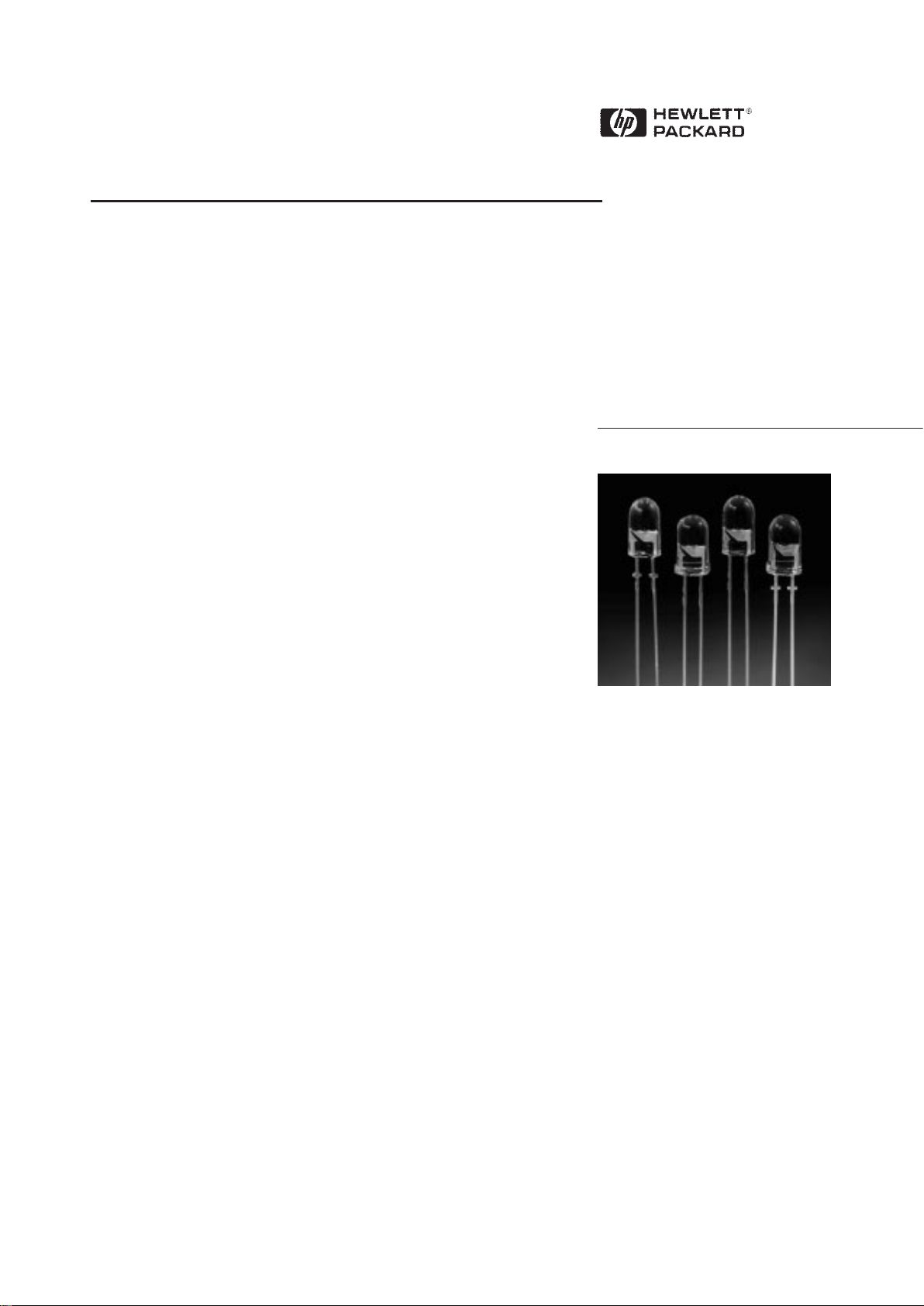
Description
These Precision Optical Performance AlInGaP LEDs provide
superior light output for excellent
readability in sunlight and are
extremely reliable. AlInGaP LED
technology provides extremely
stable light output over long
periods of time. Precision Optical
Performance lamps utilize the
aluminum indium gallium phosphide (AlInGaP) technology.
These LED lamps are untinted,
nondiffused, T-13/4 packages
incorporating second generation
optics producing well defined
spatial radiation patterns at
specific viewing cone angles.
SunPower Series
HLMP-DLXX
HLMP-DJXX
HLMP-DHXX
HLMP-DGXX
HLMP-GLXX
HLMP-GJXX
These lamps are made with an
advanced optical grade epoxy,
offering superior high temperature and high moisture resistance
performance in outdoor signal
and sign applications. The high
maximum LED junction temperature limit of +130°C enables high
temperature operation in bright
sunlight conditions. The package
epoxy contains both uv-a and
uv-b inhibitors to reduce the
effects of long term exposure to
direct sunlight.
These lamps are available in four
package options to give the
designer flexibility with device
mounting.
HLMP-GHXX
HLMP-GGXX
HLMP-ULXX
HLMP-UJXX
HLMP-UHXX
HLMP-UGXX
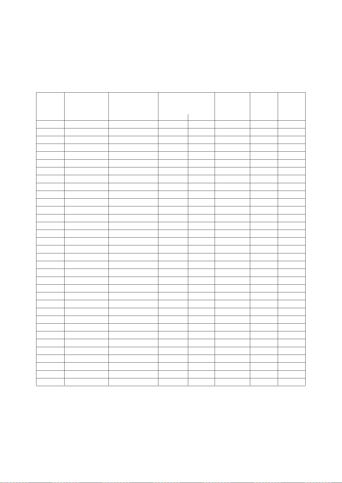
Device Selection Guide
Color, Luminous Intensity,
Part Typical Dominant I
v
(mcd),
[1,2]
Number Viewing Angle, Wavelength, @ 20 mA Leads with Flanged Package
HLMP- 2θ
1
/2 (Deg.)
[4]
λd (nm),
[3]
Typ. Min. Typ. Stand-Offs Base Drawing
DL08
[5]
6 Amber, 590 4000 9300 No Yes A
GL08
[5]
6 Amber, 590 4000 9300 No No B
DL10
[5]
6 Amber, 590 4000 9300 Yes Yes C
GL10
[5]
6 Amber, 590 4000 9300 Yes No D
UL06
[5]
6 Amber, 590 1600 4000 No Yes A
UL07
[5]
6 Amber, 590 1600 4000 Yes Yes C
DJ08
[5]
6 Orange, 605 4200 9500 No Yes A
GJ08
[5]
6 Orange, 605 4200 9500 No No B
DJ10
[5]
6 Orange, 605 4200 9500 Yes Yes C
GJ10
[5]
6 Orange, 605 4200 9500 Yes No D
UJ06
[5]
6 Orange, 605 2000 4500 No Yes A
UJ07
[5]
6 Orange, 605 2000 4500 Yes Yes C
DH08
[5]
6 Red-Orange, 615 2900 8000 No Yes A
GH08
[5]
6 Red-Orange, 615 2900 8000 No No B
DH10
[5]
6 Red-Orange, 615 2900 8000 Yes Yes C
GH10
[5]
6 Red-Orange, 615 2900 8000 Yes No D
UH06
[5]
6 Red-Orange, 615 1400 3500 No Yes A
UH07
[5]
6 Red-Orange, 615 1400 3500 Yes Yes C
DG08
[5]
6 Red, 626 2900 6500 No Yes A
GG08
[5]
6 Red, 626 2900 6500 No No B
DG10
[5]
6 Red, 626 2900 6500 Yes Yes C
GG10
[5]
6 Red, 626 2900 6500 Yes No D
UG06
[5]
6 Red, 626 1000 3000 No Yes A
UG07
[5]
6 Red, 626 1000 3000 Yes Yes C
DL15 15 Amber, 590 1600 3100 No Yes A
GL15 15 Amber, 590 1600 3100 No No B
DL17 15 Amber, 590 1600 3100 Yes Yes C
GL17 15 Amber, 590 1600 3100 Yes No D
UL13 15 Amber, 590 700 1600 No Yes A
UL14 15 Amber, 590 700 1600 Yes Yes C
DJ15 15 Orange, 605 1400 3400 No Yes A
GJ15 15 Orange, 605 1400 3400 No No B
DJ17 15 Orange, 605 1400 3400 Yes Ye s C
GJ17 15 Orange, 605 1400 3400 Yes No D
Notes:
1. The luminous intensity is measured on the mechanical axis of the lamp package.
2. The optical axis is closely aligned with the package mechanical axis.
3. The dominant wavelength, λd, is derived from the CIE Chromaticity Diagram and represents the color of the lamp.
4. θ
1/2
is the off-axis angle where the luminous intensity is one half the on-axis intensity.
5. The intensity of narrow viewing angle lamps is measured at the intensity peak.

Device Selection Guide, continued
Color, Luminous Intensity,
Part Typical Dominant I
v
(mcd),
[1,2]
Number Viewing Angle, Wavelength, @ 20 mA Leads with Flanged Package
HLMP- 2θ
1
/2 (Deg.)
[4]
λd (nm),
[3]
Typ. Min. Typ. Stand-Offs Base Drawing
UJ13 15 Orange, 605 700 1800 No Yes A
UJ14 15 Orange, 605 700 1800 Yes Yes C
DH15 15 Red-Orange, 615 1400 2500 No Yes A
GH15 15 Red-Orange, 615 1400 2500 No No B
DH17 15 Red-Orange, 615 1400 2500 Yes Yes C
GH17 15 Red-Orange, 615 1400 2500 Yes No D
UH13 15 Red-Orange, 615 500 1400 No Yes A
UH14 15 Red-Orange, 615 500 1400 Yes Yes C
DG15 15 Red, 626 1400 2100 No Yes A
GG15 15 Red, 626 1400 2100 No No B
DG17 15 Red, 626 1400 2100 Yes Yes C
GG17 15 Red, 626 1400 2100 Yes No D
UG13 15 Red, 626 500 1000 No Yes A
UG14 15 Red, 626 500 1000 Yes Yes C
DL24 23 Amber, 590 1000 1800 No Yes A
GL24 23 Amber, 590 1000 1800 No No B
DL26 23 Amber, 590 1000 1800 Ye s Yes C
GL26 23 Amber, 590 1000 1800 Yes No D
UL22 23 Amber, 590 450 1000 No Yes A
UL23 23 Amber, 590 450 1000 Yes Yes C
DJ24 23 Orange, 605 1000 2000 No Yes A
GJ24 23 Orange, 605 1000 2000 No No B
DJ26 23 Orange, 605 1000 2000 Yes Yes C
GJ26 23 Orange, 605 1000 2000 Ye s No D
UJ22 23 Orange, 605 290 1200 No Yes A
UJ23 23 Orange, 605 290 1200 Yes Yes C
DH24 23 Red-Orange, 615 700 1500 No Yes A
GH24 23 Red-Orange, 615 700 1500 No No B
DH26 23 Red-Orange, 615 700 1500 Yes Yes C
GH26 23 Red-Orange, 615 700 1500 Yes No D
UH22 23 Red-Orange, 615 290 900 No Yes A
UH23 23 Red-Orange, 615 290 900 Yes Yes C
Notes:
1. The luminous intensity is measured on the mechanical axis of the lamp package.
2. The optical axis is closely aligned with the package mechanical axis.
3. The dominant wavelength, λd, is derived from the CIE Chromaticity Diagram and represents the color of the lamp.
4. θ
1/2
is the off-axis angle where the luminous intensity is one half the on-axis intensity.
5. The intensity of narrow viewing angle lamps is measured at the intensity peak.

Device Selection Guide, continued
Color, Luminous Intensity,
Part Typical Dominant I
v
(mcd),
[1,2]
Number Viewing Angle, Wavelength, @ 20 mA Leads with Flanged Package
HLMP- 2θ
1
/2 (Deg.)
[4]
λd (nm),
[3]
Typ. Min. Typ. Stand-Offs Base Drawing
DG24 23 Red, 626 700 1300 No Yes A
GG24 23 Red, 626 700 1300 No No B
DG26 23 Red, 626 700 1300 Yes Yes C
GG26 23 Red, 626 700 1300 Yes No D
UG22 23 Red, 626 290 700 No Yes A
UG23 23 Red, 626 290 700 Yes Yes C
DL30 30 Amber, 590 700 1300 No Yes A
GL30 30 Amber, 590 700 1300 No No B
DL32 30 Amber, 590 700 1300 Yes Yes C
GL32 30 Amber, 590 700 1300 Yes No D
UL28 30 Amber, 590 300 750 No Yes A
UL29 30 Amber, 590 300 750 Yes Yes C
DJ30 30 Orange, 605 700 1500 No Yes A
GJ30 30 Orange, 605 700 1500 No No B
DJ32 30 Orange, 605 700 1500 Yes Yes C
GJ32 30 Orange, 605 700 1500 Yes No D
UJ28 30 Orange, 605 200 800 No Yes A
UJ29 30 Orange, 605 200 800 Yes Yes C
DH30 30 Red-Orange, 615 500 1100 No Yes A
GH30 30 Red-Orange, 615 500 1100 No No B
DH32 30 Red-Orange, 615 500 1100 Yes Yes C
GH32 30 Red-Orange, 615 500 1100 Yes No D
UH28 30 Red-Orange, 615 200 600 No Yes A
UH29 30 Red-Orange, 615 200 600 Yes Yes C
DG30 30 Red, 626 500 900 No Yes A
GG30 30 Red, 626 500 900 No No B
DG32 30 Red, 626 500 900 Yes Yes C
GG32 30 Red, 626 500 900 Yes No D
UG28 30 Red, 626 200 500 No Yes A
UG29 30 Red, 626 200 500 Yes Yes C
Notes:
1. The luminous intensity is measured on the mechanical axis of the lamp package.
2. The optical axis is closely aligned with the package mechanical axis.
3. The dominant wavelength, λd, is derived from the CIE Chromaticity Diagram and represents the color of the lamp.
4. θ
1/2
is the off-axis angle where the luminous intensity is one half the on-axis intensity.
5. The intensity of narrow viewing angle lamps is measured at the intensity peak.

D
C
Package Dimensions
B
A
PART NO. d
HLMP-XX10
-XX07
12.37 ± 0.25
(0.487 ± 0.010)
HLMP-XX17
-XX14
12.42 ± 0.25
(0.489 ± 0.010)
HLMP-XX26
-XX23
12.52 ± 0.25
(0.493 ± 0.010)
HLMA-XX32
-XX29
11.96 ± 0.25
(0.471 ± 0.010)
1.14 ± 0.20
(0.045 ± 0.008)
5.80 ± 0.20
(0.228 ± 0.008)
5.00 ± 0.20
(0.197 ± 0.008)
31.60
(1.244)
MIN.
0.70 (0.028)
MAX.
1.00
(0.039)
MIN.
8.71 ± 0.20
(0.343 ± 0.008)
2.54 ± 0.38
(0.100 ± 0.015)
0.50 ± 0.10
(0.020 ± 0.004)
SQ. TYP.
CATHODE
LEAD
2.35 (0.093)
MAX.
CATHODE
FLAT
1.14 ± 0.20
(0.045 ± 0.008)
5.80 ± 0.20
(0.228 ± 0.008)
5.00 ± 0.20
(0.197 ± 0.008)
31.60
(1.244)
MIN.
0.70 (0.028)
MAX.
1.00
(0.039)
MIN.
8.71 ± 0.20
(0.343 ± 0.008)
2.54 ± 0.38
(0.100 ± 0.015)
0.50 ± 0.10
(0.020 ± 0.004)
SQ. TYP.
CATHODE
LEAD
CATHODE
FLAT
d
1.50 ± 0.15
(0.059 ± 0.006)
5.00 ± 0.20
(0.197 ± 0.008)
31.60
(1.244)
MIN.
0.70 (0.028)
MAX.
1.00
(0.039)
MIN.
8.71 ± 0.20
(0.343 ± 0.008)
2.54 ± 0.38
(0.100 ± 0.015)
0.50 ± 0.10
(0.020 ± 0.004)
SQ. TYP.
CATHODE
LEAD
NOTES:
1. ALL DIMENSIONS ARE IN MILLIMETERS (INCHES).
2. LEADS ARE MILD STEEL, SOLDER DIPPED.
3. TAPERS SHOWN AT TOP OF LEADS (BOTTOM OF LAMP PACKAGE) INDICATE AN
EPOXY MENISCUS THAT MAY EXTEND ABOUT 1 mm (0.040 in.) DOWN THE LEADS.
4. RECOMMENDED PC BOARD HOLE DIAMETERS:
• LAMP PACKAGES A AND B WITHOUT STAND-OFFS: FLUSH MOUNTING AT BASE OF
LAMP PACKAGE = 1.143/1.067 (0.044/0.042).
• LAMP PACKAGES C AND D WITH STAND-OFFS: MOUNTING AT LEAD STAND-OFFS
= 0.965/0.889 (0.038/0.035).
5. FOR DOME HEIGHTS ABOVE LEAD STAND-OFF SEATING PLANE, d, LAMP PACKAGES
C AND D, SEE TABLE.
5.00 ± 0.20
(0.197 ± 0.008)
31.60
(1.244)
MIN.
0.70 (0.028)
MAX.
1.00
(0.039)
MIN.
8.71 ± 0.20
(0.343 ± 0.008)
2.54 ± 0.38
(0.100 ± 0.015)
0.50 ± 0.10
(0.020 ± 0.004)
SQ. TYP.
CATHODE
LEAD
d
1.50 ± 0.15
(0.059 ± 0.006)

Electrical/Optical Characteristics at T
A
= 25°C
Parameter Symbol Min. Typ. Max. Units Test Conditions
Forward Voltage IF = 20 mA
Amber (λd = 590 nm) 2.02
Orange (λd = 605 nm) V
F
1.98 2.4 V
Red-Orange (λd = 615 nm) 1.94
Red (λd = 626 nm) 1.90
Reverse Voltage V
R
520 VI
F
= 100 µA
Peak Wavelength: Peak of Wavelength of
Amber (λd = 590 nm) 592 Spectral Distribution
Orange (λd = 605 nm) λ
PEAK
609 nm at IF = 20 mA
Red-Orange (λd = 615 nm) 621
Red (λd = 626 nm) 635
Spectral Halfwidth ∆λ
1/2
17 nm Wavelength Width at
Spectral Distribution
1
/2 Power Point at
IF = 20 mA
Speed of Response τ
s
20 ns Exponential Time
Constant, e
-t/τ
Capacitance C 40 pF VF = 0, f = 1 MHz
Thermal Resistance Rθ
J-PIN
240 °C/W LED Junction-to-Cathode
Lead
Luminous Efficacy
[1]
Emitted Luminous
Amber (λd = 590 nm) 480 Power/Emitted Radiant
Orange (λd = 605 nm) η
v
370 lm/W Power
Red-Orange (λd = 615 nm) 260
Red (λd = 626 nm) 150
Note:
1. The radiant intensity, Ie, in watts per steradian, may be found from the equation Ie = Iv/ηv, where Iv is the luminous intensity in
candelas and ηv is the luminous efficacy in lumens/watt.
Absolute Maximum Ratings at T
A
= 25°C
DC Forward Current
[1,2,3]
............................................................ 50 mA
Peak Pulsed Forward Current
[2,3]
................................................ 70 mA
Average Forward Current
[3]
......................................................... 30 mA
Reverse Voltage (IR = 100 µA) ......................................................... 5 V
LED Junction Temperature.......................................................... 130°C
Operating Temperature .............................................. -40°C to +100°C
Storage Temperature .................................................. -40°C to +120°C
Soldering Temperature .......................................... 260°C for 5 seconds
[1.59 mm (0.060 in.) below seating plane]
Notes:
1. Derate linearly as shown in Figure 4.
2. For long term performance with minimal light output degradation, drive currents
between 10 mA and 30 mA are recommended.
3. Please contact your Hewlett-Packard sales representative about operating currents
below 10 mA.
s

Figure 2. Forward Current vs.
Forward Voltage.
Figure 3. Relative Luminous Intensity
vs. Forward Current.
Figure 4. Maximum Forward Current
vs. Ambient Temperature. Derating
Based on T
JMAX
= 130°C.
Figure 1. Relative Intensity vs. Peak Wavelength.
Figure 5. Representative Spatial Radiation Pattern for 6° Viewing Angle Lamps.
WAVELENGTH – nm
RELATIVE INTENSITY
550 600 650 700
1.0
0.5
0
AMBER
RED-ORANGE
ORANGE
RED
I
F
– FORWARD CURRENT – mA
0
0
TA – AMBIENT TEMPERATURE – °C
40 80
50
40
30
20
10
20 60 100
RθJA = 585° C/W
RθJA = 780° C/W
RELATIVE INTENSITY – %
100
0
θ – ANGULAR DISPLACEMENT – DEGREES
80
60
50
70
20
-20 -15
10
30
40
-10 0 5 10 15 20 25
90
-25 -5
CURRENT – mA
1.0
0
VF – FORWARD VOLTAGE – V
2.5
70
40
30
1.5 2.0
60
3.0
10
20
50
RED
AMBER
RELATIVE LUMINOUS INTENSITY
(NORMALIZED AT 20 mA)
0
0
IF – DC FORWARD CURRENT – mA
40
3.0
2.0
1.5
1.0
0.5
20 60
2.5

For technical assistance or the location of
your nearest Hewlett-Packard sales office,
distributor or representative call:
Americas/Canada: 1-800-235-0312 or
408-654-8675
Far East/Australasia: (65) 290-6305
Japan: (81 3) 3335-8152
Europe: Call your local HP sales office.
Data subject to change.
Copyright © 1997 Hewlett-Packard Co.
Obsoletes 5965-5265E
Printed in U.S.A. 5965-6807E (1/97)
Figure 6. Representative Spatial Radiation Pattern for 15° Viewing Angle Lamps.
Figure 7. Representative Spatial Radiation Pattern for 23° Viewing Angle Lamps.
Figure 8. Representative Spatial Radiation Pattern for 30° Viewing Angle Lamps.
RELATIVE INTENSITY – %
100
0
θ – ANGULAR DISPLACEMENT – DEGREES
80
60
50
70
20
10
30
40
90
-20 -15
-10 0 5 10 15 20 25-25 -5
RELATIVE INTENSITY – %
100
0
θ – ANGULAR DISPLACEMENT – DEGREES
80
60
50
70
20
10
30
40
90
-20 -15 -10 0 5 10 15 20 25-25 -5
RELATIVE INTENSITY – %
100
0
θ – ANGULAR DISPLACEMENT – DEGREES
80
60
50
70
20
10
30
40
90
-20 -15 -10 0 5 10 15 20 25-25 -5
 Loading...