

T-13/4 (5 mm), T-1 (3 mm),
5 Volt, 12 Volt, Integrated
H
Resistor LED Lamps
Technical Data
Features
• Integral Current Limiting
Resistor
• TTL Compatible
Requires no External Current
Limiter with 5 Volt/12 Volt
Supply
• Cost Effective
Saves Space and Resistor Cost
• Wide Viewing Angle
• Available in All Colors
Red, High Efficiency Red,
Yellow, and High Performance
Green in T-1 and
T-13/4 Packages
Description
The 5 volt and 12 volt series
lamps contain an integral current
limiting resistor in series with the
LED. This allows the lamp to be
driven from a 5 volt/12 volt
source without an external
current limiter. The red LEDs are
made from GaAsP on a GaAs
substrate. The High Efficiency
Red and Yellow devices use
GaAsP on a GaP substrate.
The green devices use GaP on a
GaP substrate. The diffused lamps
provide a wide off-axis viewing
angle.
HLMP-1600, HLMP-1601
HLMP-1620, HLMP-1621
HLMP-1640, HLMP-1641
HLMP-3600, HLMP-3601
HLMP-3650, HLMP-3651
HLMP-3680, HLMP-3681
The T-13/4 lamps are provided
with sturdy leads suitable for wire
wrap applications. The T-13/4
lamps may be front panel
mounted by using the HLMP-0103
clip and ring.
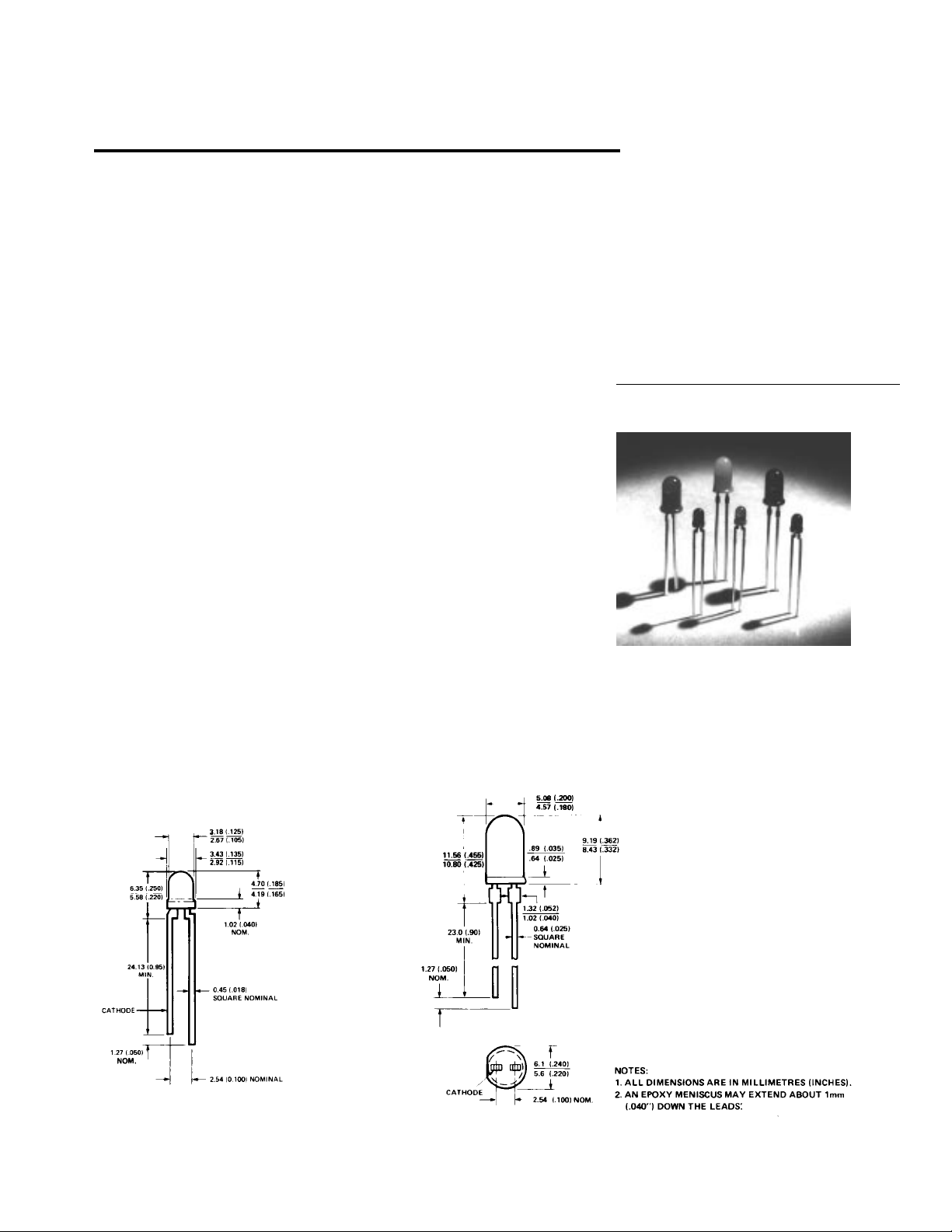
Package Dimensions
Figure A. T-1 Package. Figure B. T-13/4 Package.
5964-9296E
1-113
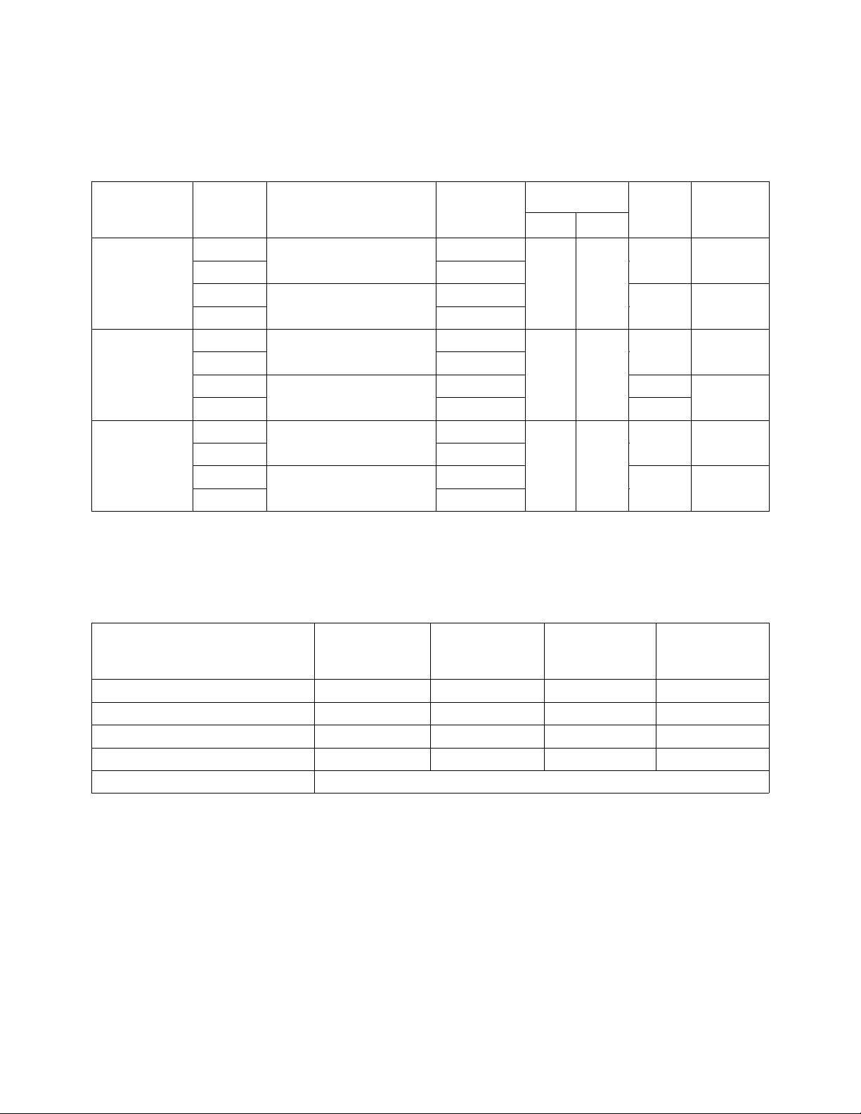
Selection Guide
Part Iv mcd
Number Operating Package
Color HLMP- Package Voltage Min. Typ. 2θ1/2
High 1600 T-1 Tinted Diffused 5 2.1 8.0 60° A
Efficiency
Red
1601 12
3600 T-13/4 Tinted Diffused 5 60° B
3601 12
Yellow 1620 T-1 Tinted Diffused 5 2.2 8.0 60° A
1621 12
3650 T-13/4 Tinted Diffused 5 60° B
3651 12
High 1640 T-1 Tinted Diffused 5 1.6 8.0 60° A
Performance
Green
1641 12
3680 T-13/4 Tinted Diffused 5 60° B
3681 12
Note:
1. θ
is the off-axis angle at which the luminous intensity is 1/2 the axial luminous intensity.
1/2
[1]
Outline
Absolute Maximum Ratings at T
= 25°C
A
Red/HER/ Red/HER/
Yellow Yellow Green Green
5 Volt Lamps 12 Volt Lamps 5 Volt Lamps 12 Volt Lamps
DC Forward Voltage (TA = 25° C) 7.5 Volts
[2]
15 Volts
[3]
7.5 Volts
[2]
15 Volts
Reverse Voltage (IR = 100 µA) 5 Volts 5 Volts 5 Volts 5 Volts
Operating Temperature Range -40°C to 85°C -40°C to 85°C -20°C to 85°C -20°C to 85°C
Storage Temperature Range -55°C to 100°C -55°C to 100°C -55°C to 100°C -55°C to 100°C
Lead Soldering Temperature 260°C for 5 seconds
Notes:
2. Derate from TA = 50°C at 0.071 V/°C, see Figure 3.
3. Derate from TA = 50°C at 0.086 V/°C, see Figure 4.
[3]
1-114

Electrical/Optical Characteristics at T
= 25°C
A
High
Efficiency Red Yellow Green
Test
Symbol Description Min. Typ. Max. Min. Typ. Max. Min. Typ. Max. Unit Condition
λ
Peak 635 583 565 nm
P
Wavelength
λ
Dominant 626 585 569 nm Note 4
d
Wavelength
∆λ1/2 Spectral Line 40 36 28 nm
Halfwidth
Rθ
Thermal 290 290 290 °C/W Junction to
J-PIN
Resistance Cathode Lead
(Note 6)
Rθ
Thermal 210 210 210 °C/W Junction to
J-PIN
Resistance Cathode Lead
(Note 7)
I
Forward 13 20 13 20 13 20 mA VF = 12 V
F
Current
12 V Devices
I
Forward 10 15 10 15 10 15 mA VF = 5 V
F
Current
5 V Devices
η
Luminous 145 500 595 lumen Note 2
V
Efficacy /Watt
V
Reverse 5.0 5.0 5.0 V IR = 100 µA
R
Breakdown
Voltage
Notes:
4. The dominant wavelength, λd, is derived from the CIE chromaticity diagram and represents the single wavelength which defines the
color of the device.
5. Radiant intensity, Ie, in watts/steradian, may be found from the equation Ie = lV/ηV, where lV is the luminous intensity in candelas and
ηV is the luminous efficacy in lumens/Watt.
6. For Figure A package type.
7. For Figure B package type.
1-115

Figure 1. Forward Current vs. Applied Forward Voltage.
5 Volt Devices.
Figure 2. Forward Current vs. Applied Forward Voltage.
12 Volt Devices.
Figure 3. Maximum Allowed Applied Forward Voltage vs.
Ambient Temperature RθJA = 175°C/W. 5 Volt Devices.
Figure 4. Relative Luminous Intensity vs. Angular
Displacement for T-1 Package.
1-116
Figure 4. Maximum Allowed Applied Forward Voltage vs.
Ambient Temperature RθJA = 175°C/W. 12 Volt Devices.
Figure 5. Relative Luminous Intensity vs. Angular
Displacement for T-13/4 Package.

Figure 6. Relative Luminous Intensity vs. Applied Forward
Voltage. 5 Volt Devices.
Figure 7. Relative Luminous Intensity vs. Applied Forward
Voltage. 12 Volt Devices.
1-117
 Loading...